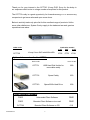
1
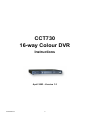
CCT730
16-way Colour DVR
Information Pack
April 2003 - Version 1.2
Thank you for your interest in the CCT730 16-way DVR. Sorry for the delay in
our response which is due to a large number of enquiries for this product.
The CCT730 really is a great opportunity for forward-thinking CCTV and security
companies to get more sales and open more doors.
Below is a strictly trade only price list for this excellent range of products. Unlike
some other distributors, System Q only supply to the trade and we seek genuine
repeat business sales.
Order Code
CCT730
Trade Price ex-VAT
1 off
3off
5 off
16-way Colour DVR with 80Gb HDD
£795
£779
£749
Optional Accessories for the CCT730
Order Code
Price ex-VAT
CCT731
USB Hard Disk Holder for
removable caddy
£89
CCT732
Spare Caddy
£20
CCT740
Spare 80Gb Hard Drive
£99
Client Software Packages
CCT730 V1.1
FREE
Unbranded Client Software
FREE
FREE
Branded Client Software via e-mail
FREE
CCT739
Branded Client Software on CD
£10
1
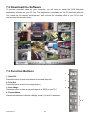
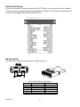
What can the CCT730 do?
The CCT730 is a digital recording device that can record video images from up to 16 cameras
simultaneously without the use of tapes or any other external recording device. Unlike switchers
or quad systems it doesn't matter what camera picture you are watching on the monitor screen
the CCT730 records all the cameras all the time.
The CCT730 records the video images on to a removable hard drive in a digital format that
enables the user to play-back images from any of the cameras at the press of a button.
With no tapes to rewind, jam or deteriorate, the CCT730 takes CCTV in to the digital age. You
can leave the CCT730 to look after itself so that as its built in hard drive gets full the unit
automatically starts to overwrite its oldest video footage first for complete unattended security.
So how long can the CCT730 record for?
The CCT730 has many options such as motion detection; external alarm inputs, scheduled
recording and more that can all extend recording time. For example, you may set the CCT730
to record only when it detects movement in a cameras picture by utilising its comprehensive
Motion Detections circuitry that can be set up for each individual channel. Or you may wish to
enable scheduled recording so that you only record in working hours, this may be suitable for
shops and similar businesses. If you want the CCT730 to record 24hrs a day everyday you can
still extend the CCT730's recording capability by automatically altering the number of frames
recorded in "day hours" to that of "night hours". All this is very easy to adjust in the simple menu
settings of the CCT730.
The CCT730 is fitted with a very easy to use "hot swapping" hard disk system that means you
can swap the hard drive in the CCT730 in seconds, this serves three purposes;
1- Extends recording times, by sensible disk rotation.
2- Allows you to have an easy and fast back up of video footage
3- Allows you to view video footage on a remote PC, for convenient viewing.
For example
You may use 2 hard drives with the CCT730. One would be in the CCT730 protecting a
business or premises and the other drive may be stored at a managers or owners home. The
manager can attach the Hard drive to his home computer and replay any of the video stored on
it at his convenience and in the privacy of his own home. If therefore an event takes place that
he thinks the CCT730 may have captured, all he needs to do is swap over the two disks so that
he has the vital evidence to study at his leisure. He may wish to swap over the disk at some
predefined regular interval. Once you have connected the hard drive to a computer you can
CCT730 V1.1
2
save the video footage to a CD (if a CD writer is connected), print off stills, email video and
more.
For a guide to CONTINUOUS RECORDING TIMES, please refer to the recording table, please
remember that these figure are easily extended by any of the above methods.
So what are the Key features of the CCT730?
§
Customisable software. We can put your company name in the "Client Software" that is
used to replay the video on a remote PC using the hot swapping hard drive. For a
professional image 24hrs a day 365 days a year.
§
Hot Swap Hard Drive. Enables the Disk drive to be swapped without stopping or
powering down the CCT730. Fast simple back up.
§
Motion Detection. Intelligent, fully adjustable and independent motion detection on all 16
channels, enabling extended and event only recording* You can even alter the sensitivity
of the motion detection to alter automatically between day and night. Please note –
Although the video motion detection is fully adjustable on sensitivity and area of detection
independently on all 16 channels once triggered the unit will record video from all 16
inputs to prevent loosing vital video information. The length of recording after video
motion detection is adjustable by the engineer.
§
Adjustable Record Quality. Adjustable record quality so that you can get the right balance
of picture quality and storage capacity. Image quality can be set to automatically adjust
between day and night settings.
§
Day & Night Setting. You could call these "working hours" and "out of working hours" and
they give the installer and customer superb flexibility in the way and what the CCT730
records.
§
Multiple Level Password protection. This means that only the right person can access the
right menus. The engineer gets to the engineer menus and the customer gets to the
end-user menus saving unwanted call-backs and hassle to all.
§
Reset to Engineers settings. This useful feature allows you at any time to reset the
system back to exactly how you installed it. Ideal if you change settings that you latter
regret!
§
Reset to factory settings. Your obvious get out of jail card.
CCT730 V1.1
3
§
Weekend Setting. In addition to the "day -night" setting you can automatically adjust how
and what the CCT730 records at the weekend as opposed to weekdays. This is a very
useful feature for Monday-Friday businesses.
§
Digital Zoom. You can digitally zoom in to a live or recorded image using the zoom
feature to get a more detailed view.
§
Camera Auto Detect. This feature automatically works out how many cameras are
connected to the system so that it does not record unwanted "blank" video footage on
unused inputs.
§
Covert Camera. This feature allows you to record cameras that cannot be seen or
detected by normal operation on the CCT730.
§
Twin monitor outputs. These allow two separate images to be displayed and adjusted on
two separate monitors. Typically one monitor may display all 16 cameras in a multiscreen
mode and one monitor is used to display full size picture of areas of interest identified on
the multiscreen monitor.
§
Independent gain control on all 16-camera inputs. As different lengths of cable to the
individual camera produce different sizes of video signal you can adjust the gain on all 16
inputs to help get the best possible picture quality.
§
Fast and Easy Video playback. As there are no tapes to change or rewind, replaying
video footage on the CCT730 is fast and easy but to prevent unwanted prying eyes the
playback function is password protected.
§
Auto-Reboot after power failure. Obviously if the CCT730 is subject to a power failure
when the power is restored if it was previously recording you would want it to carry on
recording and that’s exactly what it does.
§
Full Duplex. Whist playing back video footage the CCT730 can also carry on recording so
it never misses vital video footage.
§
Standalone System. The CCT730 has its own built in control software so it does not rely
on a PC to function; it is a true “black-box” solution.
§
Robust Reliable. Non-Windows OS. Need we say any more!
CCT730 V1.1
4
§
Alarm inputs and outputs. These can be used to trigger external devices such as
sounders and lights, or they could be used to start the CCT730 recording.
§
Day-Night input. There is even an input on the CCT730 that can be used to tell it when it
has changed to "night” hours. This could be used in conjunction with an output from a
burglar alarm panel to tell the CCT730 to automatically adjust its recording mode when
premises have been vacated at the end of a day.
Client software features include:
§
§
§
§
Multiple screen display options
Play, fast-forward, rewind, stop and pause controls
Save, delete, and cut features to make video footage into smaller sections
Emailing of video footage (requires a standard email client).
Downloads:
You can download a demo version of the CCT730 Client software from our website:
http://www.planetcc.tv/web/file/cct730d.exe
(File size 3.7Mb, estimated download time 10 mins)
CCT730 V1.1
5
If you would like the client software for the CCT730 DVR to be personalised to include your own
or your customer’s company details, please supply us with the following information in writing:
Company
Name:
Valid e-mail
address:
You can post, fax or e-mail us this information but we will need a return e-mail address to
supply you with the personalised software and its installation instructions at no charge.
If you would prefer a CD copy of the software and instructions, there is a small charge of
£10+vat inc P&P. Please tick the box below and return this sheet with your payment.
Client Software Packages
CCT730 V1.1
FREE
Branded Client Software via e-mail
FREE
o
CCT739
Branded Client Software on CD
£10
o
6
CCT730
16-way Colour DVR
Instructions
April 2003 - Version 1.2
CCT730 V1.1
7
Warning Notes
l
l
l
l
l
l
l
l
l
l
l
l
l
l
l
l
All the safety and operating instructions should be read before the CCT730 is operated.
All the safety and operating instructions should be retained for future reference.
Ensure all operating instruction and warning notes are complied with at all times.
Do not use strong or abrasive detergents when cleaning the CCT730.
There are no user-serviceable parts inside. Please contact a qualified engineer for servicing
and maintenance.
Do not expose the CCT730 to water or moisture and do not try to operate it in wet areas.
Please make sure that both ends of the power lead are plugged in.
Do not drop foreign objects through the CCT730’s case or expose it to moisture.
Do not attempt to disassemble the CCT730.
Contact a qualified engineer if the following situation happens:
Ÿ The power lead or plug is damaged.
Ÿ The CCT730 has been exposed to rain or water.
Ÿ The CCT730 does not operate normally by following the operating instructions.
Ÿ The CCT730 falls to the ground or its cover is damaged.
When replacement parts are required, make sure that the service engineer has used
replacement parts specified by System Q Ltd or that these parts have the same
characteristics as the original ones. Unauthorized substitutions may result in fire, electric
shock, or other hazards.
Use only with a mounting accessory recommended by System Q Ltd.
Never push objects of any kind into the case of the CCT730 as they may touch dangerous
voltage points or short cut parts that could result in a fire or electric shock.
If an outside cable system is connected to the CCT730, be sure that the cable system is
grounded so as to provide some protection against voltage surges and built-in static
charges.
All normal precautions to avoid component damage due to electrostatic discharge should be
taken during installation and operation.
To prevent electric shock, do not remove screws or the unit’s cover.
CCT730 V1.1
8
CONTENTS
1. Features .................................................................................................................................................11
2. CCT730 Applications ............................................................................................................................11
3. Quick Installation Guide...................................................................................................................... 12
4. CCT730 Menus .................................................................................................................................... 13
5. Front Panel........................................................................................................................................... 16
6. Menu Set-up ......................................................................................................................................... 19
6.1 Event List .................................................................................................................................... 19
6.2 OSD/ Timer ................................................................................................................................. 19
6.2.1 OSD/ Timer - Date/ Time............................................................................................... 19
6.2.2 OSD/ Timer - Date Display Mode ................................................................................ 19
6.2.3 OSD/ Timer - Date/ Time Display ................................................................................ 19
6.2.4 OSD/ Timer – PB Date/ Time Position........................................................................ 20
6.2.5 OSD/ Timer - RS485 Time Calibration........................................................................ 20
6.2.6 OSD/ Timer - Call Monitor Dwell.................................................................................. 20
6.2.7 OSD/ Timer - Text Colour.............................................................................................. 20
6.2.8 OSD/ Timer - Display Type ........................................................................................... 20
6.2.9 OSD/ Timer – OSD Display .......................................................................................... 20
6.3.Monitor Menu ............................................................................................................................. 20
6.3.1 Monitor - Video Setup .................................................................................................... 20
6.3.2 Monitor- Live Refresh Rate ........................................................................................... 20
6.3.3 Monitor - Screen Center Point ..................................................................................... 21
6.3.4 Monitor - Screen H-Size ................................................................................................ 21
6.3.5 Monitor - Background Colour ....................................................................................... 21
6.3.6 Monitor - Show Colour Bar ........................................................................................... 21
6.4 Camera Menu ............................................................................................................................ 21
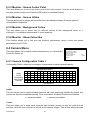
6.4.1 Camera Configuration Table 1 ..................................................................................... 21
6.4.2 Camera Auto-Detect ...................................................................................................... 23
6.4.3 Camera Title .................................................................................................................... 23
6.4.4 Power ON Detect ........................................................................................................... 23
6.4.5 Title Position.................................................................................................................... 23
6.5 Record ......................................................................................................................................... 24
6.5.1 Day/ Night........................................................................................................................ 24
6.5.2 Weekend .......................................................................................................................... 24
6.5.3 REC Event Only ............................................................................................................. 25
6.5.4 Event CH Priority............................................................................................................ 25
6.5.5 Circular Record............................................................................................................... 25
6.5.6 HDD Full Alarm ............................................................................................................... 25
6.6 Event ........................................................................................................................................... 26
6.6.1 Day/ Night Switch........................................................................................................... 26
CCT730 V1.1
9
6.6.2 Event Response ............................................................................................................. 26
6.6.3 Motion Detect.................................................................................................................. 27
6.6.4 Alarm In ............................................................................................................................ 29
6.6.5 Video Loss Detect .......................................................................................................... 29
6.6.6 Alarm Set/ Reset SW..................................................................................................... 29
6.6.7 Release Time .................................................................................................................. 29
6.6.8 Clear Eve nt List .............................................................................................................. 29
6.7 Others.......................................................................................................................................... 30
6.7.1 RS-485 ID Set Up .......................................................................................................... 30
6.7.2 RS-485 Protocol ............................................................................................................. 30
6.7.3 Software Information ..................................................................................................... 30
6.8 Save/ Load Default.................................................................................................................... 30
6.9 Engineer Set Up ........................................................................................................................ 31
6.9.1 Change Password.......................................................................................................... 31
6.9.2 Covert Cam Visible ........................................................................................................ 31
6.9.3 Playback Check.............................................................................................................. 31
6.9.4 Language......................................................................................................................... 31
6.9.5 Format Hard Disk ........................................................................................................... 31
6.9.6 System Colour ................................................................................................................ 31
6.10 Shutdown.................................................................................................................................. 31
6.11 Exit ............................................................................................................................................. 31
7. Windows Application Software .......................................................................................................... 32
7.1 Connecting the Caddy to a PC................................................................................................ 32
7.2 Download the Software ............................................................................................................ 33
7.3 Function Buttons ........................................................................................................................ 33
8. Connectors ........................................................................................................................................... 36
9. CCT730 Specification ......................................................................................................................... 38
Appendix 1: Hard Disk Error Message ................................................................................................. 39
Appendix 2: Supported HDD.................................................................................................................. 40
Appendix 3: Estimated Recording Times ............................................................................................. 41
CCT730 V1.1
10
1. Features
l
l
l
l
l
l
l
l
l
l
l
l
l
l
l
l
l
Powerful Wavelet compression
Proprietary real time Operating System.
Duplex operation: View live video and playback simultaneously
Support NTSC and PAL system
Programmable recording picture rate (up to 60 pics per sec)
Recording priority of each camera dynamically adjusted by motion detection
Hot swappable Hard Disk Drive
Windows compatible Data format
Powerful Alarm Processor allows flexible alarm trigger and response configuration
Programmable motion detection area and sensitivity for each individual camera
Different motion sensitivities available for day and night time
Intelligent algorithm refreshing main monitor display dynamically
User-friendly video search
Versatile multiple-windows display format
Password to secure installation authorization
System auto reboot after power interruption
System software stored in non-volatile memory, free from hard disk crash
2. CCT730 Applications
CCT730 is a cost-effective and easy-to-use multiplexed digital video recorder, equipped with a
proprietary real time operating system, powerful Wavelet compression engine, duplex
multiplexer and a hot swappable Hard Disc Drive.
CCT730 V1.1
11
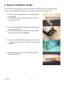
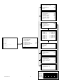
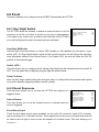
3. Quick Installation Guide
The CCT730 is equipped with a hot-swap Hard Disk Drive (HDD) that can be exchanged when
it is full. The following photos illustrate how to install the HDD into its removable caddy.
1) Pull the exterior handle towards you and unlock with the
key provided.
2) Pull the handle outwards until the caddy is free from the
case of the CCT730.
3) Push the release latch to slide the top cover backwards
and remove the HDD.
4) Insert the DC power cable and IDE cable into the HDD.
Make sure the HDD is set to “Master”.
5) Position the empty HDD into the caddy and slide the top
cover back to secure. Secure the HDD using the screws
provided.
6) Slide the caddy back into the CCT730 case and lock it
with the key provided.
CCT730 V1.1
12
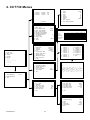
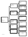
4. CCT730 Menus
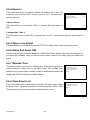
Event List
1
2
3
02/10/21
02/10/21
02/10/22
15:58:53
18:24:30
10:19:16
1
---Continue---
1
2
3
4
5
6
7
8
9
10
11
Date / Time
Date Display Mode
Date / Time Display
Date / Time Position
PB Date / Time Position
RS485 Time Calibration
Call Monitor Dwell
Text Colour
Display Type
OSD
EXIT
Monitor
MAIN MENU
1
2
3
4
5
6
7
8
9
10
11
Event List
OSD / Timer
Monitor
Camera
Record
Event
Others
Save / Load Default
Engineer
Shutdown
Exit
2002
12
4
16
5
20
MON
2
Y/M/D
2Rows
5
7
1
T&D/T
Configuration Table 1
Install
Covert
Termination
Gain Control
Call Seq
1
V
.
V
8
1
2
V
.
V
8
2
3
V
.
V
8
3
125 IIIIIIIII
190 IIIIIIIII
188 IIIIIIIII
133 IIIIIIIII
Auto
Camera
4
ON
Default
4
V
.
V
8
4
5
V
.
V
8
5
6
V
.
V
8
6
7
V
.
V
8
7
8
V
.
V
8
8
9
V
.
V
8
9
Camera Title
3
1 Brightness
2 Contrast
3 Saturation
4 Hue
5 Live Refresh Rate
6 Screen Center Point
7 Screen H-Size
8 Background Colour
2
9 Show Colour Bar
1 0 Exit
1 Configuration Table 1
2 Camera Auto-Detect
3 Camera Title
4 Power ON Detect
5 Title Position
6 Exit
2-1
1 Year
2 Month
3 Date
4 Hour
5 Minute
6 Second
7 Week
8 Exit / Update
9 Exit / Without Update
M12
A3
L16
OSD / Timer
Date / Time
1
2
3
4
5
6
7
8
9
Camera_
Camera_
Camera_
Camera_
Camera_
Camera_
Camera_
Camera_
Camera_
1
2
3
4
5
6
7
8
9
10
V
.
V
8
10
11
V
.
V
8
11
4-1
12
V
.
V
8
12
13
V
.
V
8
13
14
V
.
V
8
14
4-3
10 Camera_10
11 Camera_11
12 Camera_12
13 Camera_13
14 Camera_14
15 Camera_15
16 Camera_16
17 Exit
Camera_1
! ” # $ % & ( )
0 1 2 3 4 5 6 7 8
@ A B C D E F G H I
P Q R S T U V W X
‘ a b c d e f g h i
p q r s t u v w x
* + , _ . /
9 : : < > ?
J K L M N O
Y Z [ \ ] ^ _
j k l m n o
y z { | } ~
INPUT PASSWORD
1 Input Password
2 Enter Main Menu
3 Exit
0 0 0 0
Record
1
2
3
4
5
6
7
Day / Night
Weekend
REC Event Only
Event Ch Priority
Circular Record
HDD Full Alarm
Exit
5
OFF
Auto
ON
ON
Day / Night
1
2
3
4
5
6
7
Day Start Time
Day Stop Time
Day REC PPS
Day REC Quality
Night REC PPS
Night REC Quality
Exit
Weekend
1
2
3
4
5
6
CCT730 V1.1
13
15
V
.
V
8
15
Weekend Setting
Start
Stop
REC PPS
REC Quality
Exit
5-1
08:00
20:00
60
Normal
60
Normal
5-2
OFF
FRI
MON
60
Normal
16
V
.
V
8
16
Day / Night Switch
6-1
1 Day / Night SW Enable
2 Switch<OFF>
3 Delay For Active
4 Exit
No
Day
60
Event Response
6-2
1 Internal Buzzer
2 Event Relay Output
3 Event List
4 Event Full Screen
5 Call Event Display
6 Response Duration
7 Any Key To Stop
8 Exit
ON
ON
ON
OFF
ON
10
ON
Motion Detect
6-3
1 Motion Detect
2 Configuration Table 2
3 Condition Set Up
4 Exit
OFF
Condition Set Up
MAIN MENU
1
2
3
4
5
6
7
8
9
10
11
Event List
OSD / Timer
Monitor
Camera
Record
Event
Others
Save / Load Default
Engineer
Shutdown
Exit
Event
1
2
3
4
5
6
7
8
9
Day / Night Switch
Event Response
Motion Detect
Alarm In
Video Loss Detect
Alarm Set / Reset SW
Release Time
Clear Event List
Exit
6
1
2
3
4
5
6
7
8
9
Camera_
Camera_
Camera_
Camera_
Camera_
Camera_
Camera_
Camera_
Camera_
1
2
3
4
5
6
7
8
9
Dis
En
6-3-3
10 Camera_10
11 Camera_11
12 Camera_12
13 Camera_13
14 Camera_14
15 Camera_15
16 Camera_16
17 Exit
Camera_1
6-3-3
1 Detect Area
2 Sensitivity
3 Exit
Alarm In
6-4
1 Alarm In Detect
2 Configuration Table 2
3 Exit
OFF
Release Time
1
2
3
4
6-7
Motion RES Time
Video Loss RES Time
Alarm In RES Time
Exit
2
2
10
Clear Event List
6-8
1 Clear Event List: No
2 Clear Event List: Yes
3 Exit
Configuration Table 2
CCT730 V1.1
14
Alm In Type
Day: Alm In
Day: Motion
Night: Alm In
Night: Motion
1
O
V
V
V
V
2
O
V
V
V
V
3
O
V
V
V
V
4
O
V
V
V
V
5
O
V
V
V
V
ESC For Return
6
O
V
V
V
V
7
O
V
V
V
V
8
O
V
V
V
V
9
O
V
V
V
V
10
O
V
V
V
V
11
O
V
V
V
V
6-4-2
12
O
V
V
V
V
13
O
V
V
V
V
14
O
V
V
V
V
15
O
V
V
V
V
16
O
V
V
V
V
RS-485 Protocol
1
2
3
4
5
Others
7
1 RS-485 ID Set up
2 RS-485 Protocol
3 Software Information
4 Exit
224
1
2
3
4
5
Load
Save
Load
Load
Exit
Baud Rate:
Bits: 8
Stop: 1
Parity: None
Exit
9600
Software Information
1
2
3
4
5
6
7
Save / Load Default
7-2
8
Installer Setting
Installer Setting
Factory Setting
Factory Password
CPU Filename
FPGA Filename
Date
Video System
DSP BD HW
DSP BD SW
Exit
D6SE0100
FPGA0505
2003/01/23
NTSC
SK1V3302
SK1V3300
Load Installer Setting
MAIN MENU
8-2
1 Save / Load: No
2 Save / Load: Yes
3 Exit
Engineer
1 Change Password
2 Covert Cam Visible
3 Playback Check
4 Language
5 Format Hard Disk
6 System Colour
Colour
7 Exit
Shutdown
1
2
3
9
9999
No
OFF
English
Load Factor Setting
8-3
1 Save / Load: No
2 Save / Load: Yes
3 Exit
10
Shutdown: No
Shutdown: Yes
Exit
Format Hard Disk
1 Format Hard Disk: No
2 Format Hard Disk: Yes
3 Exit
Exit
11
1 Set Up Data: Save
2 Set Up Data: Cancel
3 Exit
CCT730
It is now safe to
remove power
CCT730 V1.1
8-1
1 Save / Load: No
2 Save / Load: Yes
3 Exit
Save Installer Setting
1 Event List
2 OSD / Timer
3 Monitor
4 Camera
5 Record
6 Event
7 Others
8 Save / Load Default
9 Engineer
10 Shutdown
11 Exit
7-3
15
9-5
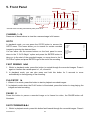
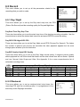
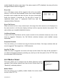
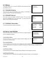
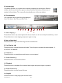
5. Front Panel
Fast Rewind
Pause
GOTO
Enter/Zoom
Play/Stop F/Forward
Channels 1-16
*CCT730 starts recording automatically after power is on.
SET SEQ
MENU ESC
Directional Arrow Keys
MODE
CHANNEL 1~16
Press one of these buttons to view the a camera image in full screen.
GOTO
In playback mode, you can press the GOTO button to access the
GOTO menu. This menu allows you to search for certain recorded
images by entering the date and time.
You can either use the arrows buttons on the front panel to move
down to the “5 GoTo Begin” option and press the ENTER button to
take you to the start of the recorded images; or move down to the “6
GoTo End” option and press ENTER to go to the end of the recording.
GOTO
1
2
3
4
5
5
6
7
Minute
Hour
Day
Month
Year
Goto Begin
Goto End
Exit
FAST REWIND It t
1. Whilst in playback mode, press this button to rewind through the recorded images. Press it
again to increase the rewind speed: x1, x2, x4 and x8.
2. In playback mode, you can also press and hold this button for 3 seconds to move
automatically to the beginning of the recording.
PLAY/STOP u
1. When in Live mode, press this button to start to playback recorded images.
2. In playback mode when the PLAY button is illuminated, press this button to stop playing the
images and start recording.
PAUSE II
Press this button to pause a recorded image or to freeze live video, the PAUSE button will
illuminate.
FAST FORWARD uuI
1. Whilst in playback mode, press this button fast forward through the recordrd images. Press it
CCT730 V1.1
16
30
20
21
11
02
again to increase the fast forward speed: x1 x2, x4 and x8.
2. In playback mode, you can also press and hold this button for 3 seconds to move
automatically to the end of the recording.
ENTER / ZOOM 8
1. In the menu screens, this button is used to “ENTER” a sub-menu or to confirm a command.
2. In full-screen mode where a live or recorded image is being displayed in full-screen, you can
also use this button to zoom (x2) into the image and then use the arrow buttons on the front
of the unit to move around the “zoomed” image. In this mode the button will be illuminated.
SET
In a split-screen display, press this button to enter SET mode where each of your cameras can
be assigned a Channel. These will relate to the Channel numbers/buttons on the front display of
the CCT730. The SET menu will appear with a cursor flashing over the first image/window. Use
the arrow buttons tupq to move the cursor to the desired camera image and then press the
desired CHANNEL or Number button to assign the camera. The cursor will move on to the next
window automatically. Press the ESC button to exit this mode.
SEQ
Sequence_1 Set Up
1. Press this button to start sequencing through the camera images
1
Pages
16
11
2
Mode
0
12
and press it again to stop sequencing. The SEQ button will be
3
Timer
Ind.
13
4
Page 1
5
14
illuminated as well as the camera channel on display when the
5
Page 2
5
15
6
Page 3
5
16
unit is in sequencing mode.
7
Page 4
5
17
8
Page 5
5
18
2. A number of different sequencing options can be obtained with the
9
Page 6
5
19
10
Page 7
5
20
CCT730. These options are set up using a menu, which can be
accessed by pressing the SET button whilst in the sequencing
mode. The number at the top of the menu indicates which Sequence you are setting up.
Page 8
Page 9
Page 10
Page 11
Page 12
Page 13
Page 14
Page 15
Page 16
Exit
Pages - this allows you to decide the total number of pages/images to be used in the
sequence. The maximum value is 16, which means that each sequence can have up to 16
pages/images.
Mode - this item allows you to decide which display mode will be used in this sequence.
“0“ represents full screen mode and “7” represents the 16-windows mode.
Sequence Timer - this item allows you to select “Com” or “Ind” Sequence Timer. “COM”
means every page in this sequence has a common dwell time; whilst IND means that each
page can have an individual dwell time.
Dwell Time and Page Setup – this allows you to set up the dwell time of each page. If the
sequence timer is selected as “COM”, once you change the dwell time of one page, the
dwell time of all the other pages will be changed as well. If the sequence timer is selected
as “IND”, the dwell time value can be changed individually page by page.
Using the arrow keys, move the cursor down to one of the page numbers and use the
CCT730 V1.1
17
5
5
5
5
5
5
5
5
5
right/ left arow buttons to change the dwell time or press the ENTER button for page setup.
MODE
Press this button to select your chosen display format (4, 5,7,9,10,13 or 16 windows). The
camera buttons of all the selected cameras will be illuminated.
MENU
Press this button to enter the on-screen set-up menus (the button will be illuminated).
ESC
In the menu screens, press this button to return to previous menu.
DIRECTION ARROWS tupq
These buttons function as directional controls in the Zoom mode and on the menu screens.
CCT730 V1.1
18
6. Menu Set-up
The CCT730 menu set-up is hierarchical and is displayed in the initial
pages of this document. The menus allow you to configure the unit
according to the applictation you will be using it for. Many functions
can be selected via these menus.
To enter the main menu, press the MENU button on the CCT730’s
front panel, the main menu will appear with a cursor over the first item.
This cursor can be moved using the up/ down buttons on the front
panel. If you wish to exit the menu at any time, you may either select
the last item on the menu “EXIT” and then press ENTER button or
simply press the ESC button on the front panel of the CCT730.
MAIN MENU
1 Event List
2 OSD / Timer
3 Monitor
4 Camera
5 Record
6 Event
7 Others
8 Save / Load Default
9 Engineer
10 Engineer
11 Exit
Event List
6.1 Event List
This item allows you to enter the Event List. Up to 255 alarm events
will be logged in the unit’s non-volatile memory on a “First In, First
Out” basis, so the latest events always remain on the list.
1
2
3
02/10/20
02/10/22
02/10/22
08:12:39
12:38:21
15:58:53
L16
A3
M12
---Continue---
OSD / Timer
6.2 OSD/ Timer
This menu item allows you to set the current date/ time, and other
On-Screen-Display (OSD) parameters. Press the ENTER button to
enter the date/time sub-menu.
1 Date/ time
2 Date Display Mode
3 Date/ Time Display
4 Date/ Time Position
5 RS485 Time Calibration
6 Call monitor Dwell
7 Text Colour
8 Display Type
9 OSD Display
10 Exit
Y/M/D
2 Rows
5
1
T&D/T
6.2.1 OSD/ Timer - Date/ Time
Items 1~7 allow you to set the date and time, use the right/ left buttons
to adjust the CCT730 to the accurate time.
If you want to save the modifications, move the cursor to the Exit/
Update option and press Enter, your settings will be memorized. If you
don’t want to save the modifications, move the cursor to the Exit /
Without Update and press the Enter button, your adjustments will be
discarded.
Date / Time
1
2
3
4
5
6
7
8
9
Year
Month
Date
Hour
Minute
Second
Week
Exit / Update
Exit / Without Update
2002
12
4
16
5
20
MON
6.2.2 OSD/ Timer - Date Display Mode
This item allows you to select a format of date display. You may use the right/ left arrow buttons
to choose from: Year/Month/Day, M/D/Y and D/M/Y.
6.2.3 OSD/ Timer - Date/ Time Display
This item allows you to select from a one or two row date/time display.
CCT730 V1.1
19
6.2.4 OSD/ Timer – PB Date/ Time Position
This item allows you to move the current Date/ Time Display to any position on your screen. Use
the directional arrow buttons to move the Date/ Time display around your screen.
6.2.5 OSD/ Timer - RS485 Time Calibration
RS-485 is used for multi-point communications: many devices can be connected to the same
bus. Move to this item and press the ETNER button, all CCT730 timers will be synchronized.
6.2.6 OSD/ Timer - Call Monitor Dwell
The call monitor display is always full screen switching of all the installed cameras, this item
allows you to set the Dwell Time between switching. The timer value ranges from 1 to 255
seconds.
6.2.7 OSD/ Timer - Text Colour
This item allows you to select from 16 different colours for the Date/ Time display.
6.2.8 OSD/ Timer - Display Type
This item allows you to select one from 6 different text types (reverse, bold…) for the Date/ Time
display.
6.2.9 OSD/ Timer – OSD Display
This item allows you to select which information you wish to display; you can choose from
•T&D/T(camera title and date/time); ‚ Title; ƒ D/T(date/time); „ OFF.
Monitor
6.3.Monitor Menu
This menu allows you to adjust the quality of the displayed image.
1 Brightness
2 Contrast
3 Saturation
4 Hue
5 Live Refresh Rate
6 Screen Center Point
7 Screen H-Size
8 Background Colour
9 Show Colour Bar
10 Exit
125IIIIIIII
190IIIIIIII
188IIIIIIII
133IIIIIIII
Auto
6.3.1 Monitor - Video Setup
Items 1~4 involve adjusting the brightness, contrast, saturation and hue of the attached
cameras. Use the front panel arrow buttons to adjust these values.
6.3.2 Monitor- Live Refresh Rate
This item allows you to set-up the camera refresh rate on the Main monitor; use the right/ left
arrow buttons to select between Fix or Auto. “Fix” means each camera has the same refresh
rate. “Auto” means the camera where more motion is detected will receive a higher refresh rate
automatically.
CCT730 V1.1
20
6.3.3 Monitor - Screen Center Point
This item allows you to move the center point of the main monitor. Use the arrow buttons to
move the monitor center point. Press the ESC button to exit when finished.
6.3.4 Monitor - Screen H-Size
This item allows you to change the horizontal size of the displayed image. Press the right/ left
arrow buttons to adjust this.
6.3.5 Monitor - Background Colour
This item allows you to select from 16 different colours for the background colour of •
video-loss, ‚ un-installed cameras and ƒ covert situations.
6.3.6 Monitor - Show Colour Bar
This function allows you to fine tune the monitor’s performance using a colour bar pattern
generated by the CCT730.
6.4 Camera Menu
Camera
This menu allows you to adjust camera-related items, ex. Camera title,
Power On Detect, etc.
1
2
3
4
5
6
Configuration Table 1
Camera Auto-Detect
Camera Title
Power ON Detect
Title Position
Exit
ON
Defaul
6.4.1 Camera Configuration Table 1
Configuration Table 1 allows you to configure 5 parameters for each individual camera.
Configuration Table 1
Install
Covert
Termination
Gain Control
Call Seq
1
V
·
V
8
1
2
V
·
V
8
2
3
V
·
V
8
3
4
V
·
V
8
4
5
V
·
V
8
5
6
V
·
V
8
6
7
V
·
V
8
7
8
V
·
V
8
8
9 10 11 12 13 14 15 16
V V V V V V V V
·
·
·
·
·
·
·
·
V V V V V V V V
8 8 8 8 8 8 8 8
9 10 11 12 13 14 15 16
ESC For Return
Install
This item allows you to install individual cameras with each one being installed by default. Any
camera can then be un-installed manually. Once un-installed, all related functions are disabled.
v = camera installed
• = camera not installed
Covert
This item allows you to make each camera’s input invisible (covert) on both the main and call
monitors, while the unit continues to record all the camera images. This is ideal where cameras
CCT730 V1.1
21
are installed covertly. The default setting is to have every camera visible.
v = covert
• = not covert
Termination
This allows you to enable or disable the video loop-through output for each camera channel. If
the camera loop-through is not used, this setting should be enabled to get correct signal
termination. This is the default condition.
v = Termination enabled
• = Termination disabled
Gain Control
This item allows you to adjust the camera’s video level. You may adjust the value between 1
and 16 for each camera.
REC Priority
This item allows the user to set the recording priority for each camera under a normal state (No
alarm occurred). The CCT730 will record the camera that is assigned with a higher priority more
frequently. The user can move the cursor and use the ENTER key to adjust the value. The value
ranges from 1 to 16; “1” stands for the lowest priority; “16” stands for the highest priority. If the
camera is not installed, the priority will be set to 0 automatically.
Alarm REC Priority
This item allows you to set the recording priority when an alarm is triggered for the current
channel, either by Alarm In or by Motion.
For example:
If you set the PPS rate to “30”, the record priority of the channel to level ”4”, and the record
priority of all the other channels to level “1’, then each channel’s PPS can be calculated by the
formula below.
Situation 1: No alarm event occurs.
Channel 1 PPS = 30 *
4
= 6.31
4 +1 +1 + 1+ 1 +1 +1 + 1+ 1 +1 +1 + 1 +1 +1 + 1+ 1
Channel 2 PPS = 30 *
1
= 1.58
4 +1 +1 + 1+ 1 +1 +1 + 1+ 1 +1 +1 + 1 +1 +1 + 1+ 1
Channel 3 PPS = 30 *
1
= 1.58
4 +1 +1 + 1+ 1 +1 +1 + 1+ 1 +1 +1 + 1 +1 +1 + 1+ 1
CCT730 V1.1
22
Situation 2: An alarm event occurs on channel 2.
Channel 1 PPS = 30 *
4
= 4.61
4 + 8 +1 +1 + 1+ 1 +1 +1 + 1+ 1 +1 +1 + 1+ 1+ 1 +1
Channel 2 PPS = 30 *
8
= 9.23
4 + 8 +1 +1 + 1+ 1 +1 +1 + 1+ 1 +1 +1 + 1+ 1 +1 +1
Channel 3 PPS = 30 *
1
= 1.15
4 + 8 +1 + 1+ 1 +1 +1 + 1+ 1 +1 +1 + 1+ 1 +1 +1 + 1
Call Seq
The Call monitor sequence mode has 16 programmable steps. This item allows you to assign a
camera for each programmable step (1~16), “0” means skip this step. Those cameras, which
are not installed or are set as covert will not be displayed on the call monitor.
6.4.2 Camera Auto-Detect
The CCT730 is able to auto-detect which and how many cameras are connected to it by looking
for their video signal. If a camera channel is not used, it is recommended that it is set as “not
installed”. Otherwise that channel will detected as suffering from “video loss”. Move back to the
Configuration Table 1 menu to un-install a camera.
6.4.3 Camera Title
Camera Title
Each camera can be assigned a title up to 12 characters long. The
default title for each camera is their channel number, eg, Camera_1.
Move the cursor to the Camera Title option and press ENTER, the list
of camera titles will appear. Select a channel and press ENTER again,
the character sub-menu will appear.
Use the arrow buttons to select your chosen character and press
ENTER to add it to the title. If the wrong character is entered, the
MODE button on the front panel of the CCT730 also doubles as a
backspace key. NB. the first character on the full list of characters is a
space.
1
2
3
4
5
6
7
8
9
Camera_1
Camera_2
Camera_3
Camera_4
Camera_5
Camera_6
Camera_7
Camera_8
Camera_9
10
11
12
13
14
15
16
17
Camera_10
Camera_11
Camera_12
Camera_13
Camera_14
Camera_15
Camera_16
Exit
Camera_1
! ” # $ % & ( ) * + , _ . /
0 1 2 3 4 5 6 7 8 9 : : < > ?
@ A B C D E F G H I J K L M N O
P Q R S T U V W X Y Z [ \ ] ^ _
‘ a b c d e f g h i j k l m n o
p q r s t u v w x y z { | } ~
6.4.4 Power ON Detect
This item allows you to enable /disable the camera auto-detection when the power is on. The
default setting is ON.
6.4.5 Title Position
The camera title can be placed in one of five positions in the display window: Default, Top-R
(top-right), Top-L (top-left), Bom-R (bottom-right) and Bom-L (bottom-left).
CCT730 V1.1
23
6.5 Record
Record
This menu allows you to set up all the parameters related to the
recordings that you wish to make.
1
2
3
4
5
6
7
Day / Night
Weekend
REC Event Only
Event CH Priority
Circular Record
HDD Full Alarm Out
Exit
OFF
Auto
OFF
ON
6.5.1 Day/ Night
Day / Night
This menu allows you to set up the Day start/ stop time, the PPS
(Picture Per Second) and the recording quality for Day and Night-time.
1
2
3
4
5
6
7
Day Start Time
Day Stop Time
Day REC PPS
Day REC Quality
Night REC PPS
Night REC Quality
Exit
08:00
18:00
60
Normal
60
Normal
Day Start Time/ Day Stop Time
These two items allow you to set the start/ stop time of the daytime recording schedule. Use the
arrow buttons to select the desired start/ stop time and press ENTER to save the setting.
Day REC PPS/ Night REC PPS
These two items allow you to set the Day/ Night record PPS (Pictures Per Second). The higher
the number of pictures per second, the smoother the video playback appears but the more
storage space is taken up on the hard drive.
Day REC Quality/ Night REC Quality
These two items allow you to set up the Day/ Night record quality. A superior picture quality
affects playback but will fill the hard disk faster and the total record time will be shorter. Options
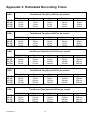
are Low, Normal, High, Super and Ultra. See Appendix 3 for a more comprehensive list of
estimated recording times.
HDD
size
40 GB
80 GB
120 GB
160 GB
Quality: Ultra
5
10
15
20
Total Record Time (Hour)
Quality: Super
Quality: High Quality: Normal
7
9
12
14
18
24
21
27
36
28
36
48
6.5.2 Weekend
Weekend
This menu allows you to set up weekend start/ stop times, the
recording PPS and the recording quality. It is programmed in the
same way as the Day/night schedules.
CCT730 V1.1
Quality: Low
15
30
45
60
24
1
2
3
4
5
6
Weekend Setting
Start
Stop
REC PPS
REC Quality
Exit
OFF
FRI
MON
60
Normal
Weekend Setting
This item allows you to enable/ disable the weekend-related functions. If the item is set to “OFF”,
all the weekend related functions will be disabled.
Weekend Start Time/ Weekend Stop Time
These allow you to set up weekend start/ stop time.
Weekend REC PPS
This item allows you to set weekend record PPS (Pictures Per Second).
Weekend REC Quality
This item allows you to set up the weekend record quality
6.5.3 REC Event Only
This item allows the CCT730 to be set up to record alarm events only. When this option is set to
ON, the unit will only record when an event occurs.
6.5.4 Event CH Priority
This option allows you to give a certain camera priority in the event recording. Using the
right/left arrows you can select either FIX or Auto. FIX gives all the channels the same priority
and Auto gives the channel a higher priority. Having a higher priority means that the channel will
be recorded more often than the others. This is a useful feature where cameras are used to
protect particularly vulnerable areas.
6.5.5 Circular Record
The CCT730 can store recorded video information in rotation. If this setting is ON (default), the
earliest recorded images will be over-written automatically when the hard disk becomes full
(none-stop recording). If the Circular Record setting is OFF, the recording will stop when the
HDD is full. In this situation, a flashing message (HD Full) will be displayed when there is only
45 minutes of recording space left on the disk and a buzzer (if on) will activate when 15 minutes
is left.
6.5.6 HDD Full Alarm
If you select ON for this item, the buzzer will be activated when
there is 15 minutes of recording time left on the HDD. This buzzer
will stop when a new HDD has been inserted.
CCT730 V1.1
25
Event
1
2
3
4
5
6
7
8
9
Day / Night Switch
Event Response
Motion Detect
Alarm In
Video Loss Detect
Alarm Set / Reset SW
Release Tim e
Clear Event List
Exit
Dis
En
6.6 Event
This menu allows you to configure how an EVENT is handled by the CCT730.
6.6.1 Day/ Night Switch
Day/ Night Switch
The CCT730 allows the installer to attach an external device to its I/O
connector to tell the unit when it should use its day or night settings.
This might be an output from an alarm panel that tells the CCT730 to
move into its Night mode when the panel has been activated.
1
2
3
4
Day / Night SW Enable
Switch <OFF>
Delay For Active
Exit
No
Day
60
Day/ Night SW Enable
Use the right/ left arrow buttons to select YES (enable) or NO (disable) for this option. If you
select “NO”, the Day/ Night Switch signal will be ignored and the unit will follow the day/night
timer schedules defined in the Record menu. If you select YES, the unit will follow the On/ Off
position of the external trigger.
Switch <OFF>
This item allows you to configure which setting (Day/ Night) will be activated when the switch is
OFF. You may select Day or Night by using the right/ left arrow buttons.
Delay For Active
After the Day/ Night switch setting has changed, there is a delay before the process takes place
to avoid the operator triggering a false event by mistake.
6.6.2 Event Response
This sub-menu allows you to set how the CCT730 will respond to a
triggered event.
Internal Buzzer
This item allows you to set an internal buzzer to activate when an
event is triggered.
Event Response
1
2
3
4
5
6
7
8
Internal Buzzer
Event Relay Output
Event List
Event Full Screen
Call Event Display
Response Duration
Any Key To Stop
Exit
ON
ON
ON
OFF
ON
10
ON
Event Relay Output
There are two alarm output relays available on the unit’s I/O connector, Alarm N.O. (normally
open) and Alarm N.C. (normally closed). These signals are driven by an on-board relay and can
be used to drive a light or siren to warn the operator of an alarm event. This item allows you to
CCT730 V1.1
26
enable/ disable the alarm o utput pins. If the alarm output is OFF (disabled), the relay will not be
energized when an alarm is triggered.
Event List
Up to 255 alarm events will be logged in the unit’s non-volatile
memory. A full list can be accessed on this menu, which displays
the alarm event number, the date, the time, the type of event and
finally the channel it occurred on. For the type of event “A”
represents Alarm Input, “L” represents Video Loss, and “M”
represents Motion Detection.
Event List
1
2
3
02/10/20
02/10/22
02/10/22
08:12:39
12:38:21
15:58:53
L16
A3
M12
---Continue---
Event Full Screen
When an event occurs on any camera input, the image from this camera can be displayed on
the main monitor in a full screen display and kept until its response duration has passed. This
option allows you to enable/ disable this function.
Call Event Display
If set to YES, the Call Monitor will be made to switch to the activated camera as soon as an
event is triggered. Otherwise, the Call Monitor switches between each installed camera
sequentially.
Response Duration
This item allows you to decide how long the buzzer and Alarm Out relays continue after an
event is triggered. This ranges from 1~9999 seconds.
Any Key To Stop
When the event is triggered, the buzzer will beep and the Alarm Out relay will be activated. If
you want to stop these actions by pressing any one key on the front panel of the CCT730, then
you must select YES for this item.
6.6.3 Motion Detect
This menu allows you to configure how the Motion Detection feature
operates. Each camera channel can have its own “Detect Area” and
“Sensitivity” individually defined.
Motion Detect
This item allows you to globally enable/ disable the motion detect
function of the CCT730.
CCT730 V1.1
27
Motion Detect
1
2
3
4
Motion Detect
Configuration Table 2
Condition Set Up
Exit
OFF
Configuration Table 2
Select Configuration Table 2 and press ENTER button so that the following table appears.
This table allows you to enable/ disable the day and night motion-detect functions.
Configuration Table 2
Alm In Type
Day: Alm In
Day: Motion
Night: Alm In
Night: Motion
1
O
v
v
v
v
2
O
v
v
v
v
3
O
v
v
v
v
4
O
v
v
v
v
5
O
v
v
v
v
6
O
v
v
v
v
7
O
v
v
v
v
8
O
v
v
v
v
9
O
v
v
v
v
10
O
v
v
v
v
11
O
v
v
v
v
12
O
v
v
v
v
13
O
v
v
v
v
14
O
v
v
v
v
15
O
v
v
v
v
16
O
v
v
v
v
ESC For Return
Condition
Condition Set Up
This menu allows you to setup each camera’s motion detector
area and sensitivity. You may select one camera from the list and
press the ENTER button; then the following sub-menu will appear.
1
2
3
4
5
6
7
8
9
Camera_1
Camera_2
Camera_3
Camera_4
Camera_5
Camera_6
Camera_7
Camera_8
Camera_9
10
11
12
13
14
15
16
17
Camera_10
Camera_11
Camera_12
Camera_13
Camera_14
Camera_15
Camera_16
Exit
Camera_1
1 Detect Area
2 Sensitivity
3 Exit
Detect Area
This item allows you to setup the motion detect area of each
camera. The screen is covered by 192 (16x12) “detection grids”.
You can use the arrow buttons to move the cursor and then press
ENTER to enable/ disable the grids. Pressing the MODE button will
change the size of the cursor and you can also toggle each grid on
or off by pressing SET button.
? Disabled
?
Enabled
? ? ? ? ? ? ? ? ? ? ? ? ? ? ? ?
? ? ? ? ? ? ? ? ? ? ? ? ? ? ? ?
? ?
? ?
? ?
? ?
? ?
? ?
? ?
? ? ? ? ? ? ? ? ? ? ? ?
? ? ? ? ? ? ? ? ? ? ? ?
? ? ? ? ? ? ? ? ? ? ? ?
? ? ? ? ? ? ? ? ? ? ? ?
? ? ? ? ? ? ? ? ? ? ? ?
? ?
? ? ? ? ? ? ? ? ? ? ? ?
? ? ? ? ? ? ? ? ? ? ? ?
? ?
? ? ? ? ? ? ? ? ? ? ? ?
Sensitivity
This item allows you to setup the threshold of the motion detection.
The first bar shows the current detected amount of motion of this
camera. The second and third bar allows you to setup the day and
night thresholds or “trigger level”. Once the detected amount of
motion becomes larger than this level, the alarm will be triggered.
CCT730 V1.1
28
? ?
? ?
MOTION
THRESHOLD: DAY
THRESHOLD: NIGHT
? ?
? ?
? ?
6.6.4 Alarm In
This menu allows you to enable/ disable the Alarm pins of rear I/O
connector and to select N.O. (normal open) or N.C. (normal close)
type for each pin.
Alarm In
1 Alarm In Detect
2 Configuration Table 2
3 Exit
OFF
Alarm In Detect
This item allows you to enable (YES) or disable (NO) the Alarm In
pins.
Configuration Table 2
This item allows you to select N.O. (normal open) or N.C. (normal close) type for each Alarm In
pins.
6.6.5 Video Loss Detect
This item allows you to enable/ disable the CCT730 to detect Video Loss as an alarm event.
6.6.6 Alarm Set/ Reset SW
This item allows you to enable/ disable the Alarm Set/ Reset signal of the rear I/O connector. If
you select EN (enable), then you can force the alarm output to on/ off by using the Alarm Set
signal.
6.6.7 Release Time
This menu allows you to set the “release time” of an alarm trigger from
motion detection, video loss or an alarm input. The release time
defines how long time after an alarm condition ends should another be
recognized. This should help avoid false alarms.
6.6.8 Clear Event List
1
2
3
4
Motion RES Time
Video Loss RES Time
Alarm In RES Time
Exit
Clear Event List
This menu allows you to clear alarm event list. By selecting the Clear
Event list menu, you are presented with 2 further options , NO or YES.
This extra menu is to prevent you from clearing the list in error.
CCT730 V1.1
Release Tim e
29
1 Clear Event List: No
2 Clear Event List: Yes
3 Exit
2
2
10
6.7 Others
Others
This menu allows you to check the RS485 communication protocol
and software version.
1
2
3
4
RS-485 ID Set up
RS- 485 Protocol
Software Information
Exit
6.7.1 RS-485 ID Set Up
This item can only be accessed by the installer; the RS-485 ID
address of the CCT730 can be modified here.
6.7.2 RS-485 Protocol
RS-485 Protocol
This menu shows the details of RS-485 protocol. The only setting
that can be changed here is the “Baud Rate”. You can choose form
38400, 19200, 9600, 4800 and 2400.
1
2
3
4
5
Baud Rate:
Bits: 8
Stop: 1
Parity: None
Exit
6.7.3 Software Information
9600
Software Information
This menu presents the software information.
1
2
3
4
5
5
6
CPU Filename
FPGA Filename
Date
Video System
DSP BD HW
DSP BD SW
Exit
6.8 Save/ Load Default
D6SE0100
FPGA0505
2002/ 01/23
NTSC
SK1V3302
SK1V3300
Save/ Load Default
This menu allows you to restore the CCT730 to the default installer or
factory configuration settings.
1
2
3
4
5
Load Installer Setting
Save Installer Setting
Load Factory Setting
Load Factory Password
Exit
Load Installer Setting
Load Installer Setting
This item allows you to recall the original “Installer Setting” from the
on-board non-volatile memory.
1 Save/ Load: No
2 Save/ Load: Yes
3 Exit
Save Installer Setting
This item allows you to save the current setting as the new “Installer setting”. This operation can
only be executed with an engineer’s password otherwise an illegal operation message will be
displayed.
Load Factory Setting
This item allows you to recall the default “Factory Setting” from the read only memory.
Load Factory Password
This item allows you to reload the factory password in case you forget your own password.
CCT730 V1.1
30
6.9 Engineer Set Up
If you enter the main menu with the engineer’s password, you can enter this menu.
Engineer Set Up
1
2
3
4
5
6
6.9.1 Change Password
Change Password
Covert Cam Visible
Playback Check
Language
Format Hard Disk
Exit
9999
Yes
OFF
English
This password can be changed to any four-digit number using the
right/ left arrow buttons to change it to a new number, press the
ESC button when you have finished and the password will be
saved into the unit’s memory. If the user forgets this new password, he can recall the factory
password by using the Load Factory Password in the Save/ Load Default sub-menu.
6.9.2 Covert Cam Visible
This option should be marked as YES is you wish to view the video playback from the cameras
that you have marked as COVERT.
6.9.3 Playback Check
This item allows you to check the internal cabling of CCT730 is
functioning correctly. A small number of Error Fields is permissible for
the system to be functioning correctly.
Input Fields: 2623
Error Fields: 13
6.9.4 Language
Only the English version is currently available.
6.9.5 Format Hard Disk
This item allows you to format the HDD. To format, choose option 2
and press ENTER. The unit formats the HDD to Windows FAT32. If
the HDD has been used in another machine with another kind of file
system, it must be formatted to FAT32 in CCT730 before starting the
recording process.
6.9.6 System Colour
Format Disk
1 Format Hard Disk: No
2 Format Hard Disk: Yes
3 Exit
Shutdown
This item allows you to choose “Colour” or “Mono” for the system.
1 Shutdown: No
2 Shutdown: Yes
3 Exit
6.10 Shutdown
This item allows you to shutdown the CCT730.
Exit
6.11 Exit
Before exiting the menus, to save your modifications in the unit’s
memory, you will need to select option 1, the Set Up Data Save
option.
CCT730 V1.1
31
1 Set Up Data: Save
2 Set Up Data: Cancel
3 Exit
7. Windows Application Software
The file format of CCT730 is compatible with Windows OS; you can process your recorded
video images in Windows 98, 2000 and XP. The application software allows you to playback,
print out, export JPEG files or clip a segment of video.
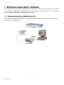
7.1 Connecting the Caddy to a PC
Remove the hot-swap HDD from the CCT730 and insert it into a caddy. Then connect the caddy
to the PC with a USB Cable.
CCT730 DVR
CCT730 V1.1
32
7.2 Download the Software
To process recorded video on your computer, you will need to install the DVR Windows
application software on your PC first. This application is available on the CD enclosed with the
unit. Install the file named “dvrwinap.exe” and connect the hot-swap HDD to your PC to view
and process the recorded video.
7.3 Function Buttons
1
1. Open File
Press this button to open and search a recorded video file.
2. Print Out
Press this button to print out a single picture.
3. Save Image
2
3
Press this button to save a current image as a JPEG on your P.C.
4. Display Mode
Press these buttons to choose a display mode (4, 9 and 16 windows).
4
CCT730 V1.1
33
5. Set (top right)
This button will allow you to select which camera is displayed in each window. Select a
window with the mouse and then press a channel button at the bottom of the screen to
assign it to that window. The cursor will automatically move to the next window.
6. File Information
The information on the open file will be displayed
here: File Name, Start Time and End Time.
7
8
9
14
10
11
12
15 16
17
13
7. Video Clipping %
Press this button to clip a small period of video so that it can be more easily forwarded by e-mail.
Press this button to start clipping and press it again to stop.
8. Back to Start Itt
Press this button to go to the first image of the recorded video.
9. Fast Rewind tt
Press this button to rewind the recorded video. Press it again to increase the rewind speed: x1,
x4, x8, x16, x32 and x64.
10. Rewind t
Press this button to rewind the recorded video at normal speed.
11. Frame Rewind (-)
Press this button to move back a frame.
12. Playback
Press this button to playback the recorded video images and press it again to pause it.
13. Frame Forward (+)
Press this button to move forward a frame.
14. Stop ¢
Press this button to stop playing the recorded video.
CCT730 V1.1
34
15. Fast Forward uu
Press this button to play the recorded video in forward direction. Press this button repeatedly to
change the playback speed: x1, x4, x8, x16, x32, and x64.
16. Go to End uuI
In playback mode, press this button to go to the end image of the opened file.
17. GOTO
In playback mode, press this button to search for a certain date and time on the recorded video.
18. Select Channel 1~16
Press one of these buttons to view any of the channels in full screen.
17
CCT730 V1.1
35
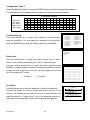
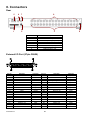
8. Connectors
Rear
5
1
6
7
8
2
3
Item
1
2
3
4
5
6
7
8
4
Description
External I/O
Monitor output
Video Loopthroughs (1~16)
Power Socket
RS-485
Call Monitor (BNC)
Monitor Output (BNC)
Video Inputs (1~16)
External I/O Port (37pin DSUB)
Pin No.
1
2
3
4
5
6
7
8
9
10
11
12
13
14
15
16
17
18
19
CCT730 V1.1
Definition
GND
GND
GND
GND
Reserved
Reserved
Alarm NO
Alarm COM
Alarm NC
GND
GND
GND
GND
GND
GND
Alarm In 16
Alarm In 15
Alarm In 14
Alarm In 1
Direction
Power
Power
Power
Power
Output
Output
Output
Power
Power
Power
Power
Power
Power
Input
Input
Input
Input
Pin No.
20
21
22
23
24
25
26
27
28
29
30
31
32
33
34
35
36
37
36
Definition
Reserved
Reset Alarm
Day / Night output
Day / Night switch
Set Alarm
Reserved
Alarm In 13
Alarm In 12
Alarm In 11
Alarm In 10
Alarm In 9
Alarm In 8
Alarm In 7
Alarm In 6
Alarm In 5
Alarm In 4
Alarm In 3
Alarm In 2
Direction
Input
Input
Output
Input
Input
Input
Input
Input
Input
Input
Input
Input
Input
Input
Input
Input
Input
External I/O Board
There is an “External I/O board” included in the CCT730 box. You can connect it to the External
I/O port; the pins are identified as the names listed on the board. Three pins are listed which are
not used: VCR Trigger, RS-232 RX and RS-232 TX.
RS-485 (RJ11)
The default RS-485 port connector is RJ11 6P6C connector.
RJ11 Cable 6P6C pin definition:
Pin No.
1
2
3
4
5
6
CCT730 V1.1
Definition
+ 12V
GND
DA (D +)
DB (D - )
-
37
Direction
Power
Ground
I/O
I/O
-
9. CCT730 Specification
Compression Method
Video System
Resolution-Live Video
Resolution-Recorded
Recording Rate
Recording Device
Recording Quality
Video Input
Video Looping Through
Main Monitor Output
Call Monitor Output
Alarm Input
Alarm Output
Remote Control
Playback Speed
Zoom
Power Supply
Title
Alarm List
Dimensions
Operating Temperature
CCT730 V1.1
Wavelet
PAL
720 x 576 pixels
720 x 288 pixels
Up to 50 pictures per second
Hot swappable HDD
Super / High / Normal / Low
BNC x 16, 1.0 V p-p, 75 Ω
BNC x 16, 1.0 V p-p, 75 Ω
BNC x 1, S-VHS x 1, 1.0 V p-p, 75 Ω
BNC x 1, 1.0 V p-p, 75 Ω
x 16, DSUB 37 pin male (TTL level)
x 1, DSUB 37 pin male, 2.0 A / 24 V
RS-485 DSCP
Fast Forward / Rewind (x1~x8), picture by picture
Yes
DC 12 V / 4 A
12 characters
Up to 255 events
432 x 44 x 400mm (W x H x D)
0~40°C
38
Appendix 1: Hard Disk Error Message
Some messages will be shown on the screen when the H.D.D. is unable to operate.
u Message: H.D.D. Detect Time Out
Symptom: The system checks the H.D.D. but gets no response for over 30 seconds
Possible reason: H.D.D. power on failure
Tip: 1. Wait for the DVR to automatically reset the H.D.D.
2. Power off and on again
u Message: No Hard Disk
Symptom: No HDD has been found by the system.
Possible reason: 1. No H.D.D.
2. H.D.D. detects a failure
Tip: 1. Insert a formatted (FAT 32) H.D.D.
2. Check the power/ IDE bus connectors, ensure they are connected
properly and then insert the H.D.D. again.
u Message: File System Error
Symptom: The file system is not acceptable.
Possible reason: The H.D.D. has not been formatted with the “FAT32” file system.
Tip: Enter menu screens and reformat the H.D.D.
u Message: IDE Bus Error
Symptom: IDE bus error or H.D.D. Master/ Slave jumper error.
Possible reason: 1. The cable of IDE connectors may be damaged.
2. H.D.D. jumper may not be set to “Master”.
Tip: 1. Check the cable of IDE connectors; it may be damaged.
2. Check the H.D.D. cable and ensure it has been connected properly to
the caddy.
3. Check H.D.D. jumper; the jumper must be set to “Master”.
u Message: Unknown H.D.D.
Symptom: The H.D.D. format is not acceptable.
Possible reason: The H.D.D. has been formatted with “NTFS” file system.
Tip: Enter the menu screens and format the H.D.D. again.
u Message: H.D.D. Detect Error
Symptom: H.D.D. is unusable.
Possible reason: Other unknown reasons.
Tip: Exchange the H.D.D. for a new one.
CCT730 V1.1
39
Appendix 2: Supported HDD
The supported H.D.D.s are listed as below:
Brand
Maxtor
Maxtor
Maxtor
Maxtor
Maxtor
Maxtor
SAMSUNG
Seagate
Seagate
Seagate
IBM
IBM
IBM
IBM
IBM
Western Digital
Western Digital
Western Digital
Western Digital
Western Digital
Western Digital
Capacity
40GB
80GB
80GB
120GB
160GB
200GB
40GB
40GB
60GB
120GB
61.5GB
76.8GB
82.3GB
123.5GB
185GB
80GB
40GB
60GB
80GB
120GB
200GB
Rotation Speed
5400 RPM
5400 RPM
7200 RPM
5400 RPM
5400 RPM
5400 RPM
5400RPM
7200RPM
7200RPM
7200RPM
7200RPM
7200RPM
7200RPM
7200RPM
7200RPM
7200RPM
5400RPM
5400RPM
5400RPM
5400RPM
7200RPM
Part Number
4D040k2
4D080H4
D740X-6L
4G120J6
4G160J8
4G200J8
SV4002H
ST340021A
ST360021A
ST3120023A
IC35L060AV
DTLA30707S
IC35L080AV
IC35L120AV
IC35L180AV
WD800JB
WD400EB
WD600AB
WD800AB
WD1200AB
WD2000JB
NB
The CCT730 cannot support Seagate 80GB HDD (P/N 9T6006-003 firmware 3.19).
CCT730 V1.1
40
Appendix 3: Estimated Recording Times
HDD
40 GB
80 GB
120 GB
160 GB
Total Record Time (Hrs) at 50 Pics per second
Ultra Quality
5 hrs
10 hrs
15 hrs
20 hrs
Ultra Quality
10 hrs
20 hrs
30 hrs
40 hrs
HDD
40 GB
80 GB
120 GB
160 GB
Ultra Quality
20 hrs
40 hrs
60 hrs
80 hrs
CCT730 V1.1
Low
15 hrs
30 hrs
45 hrs
60 hrs
Super
14 hrs
28 hrs
41 hrs
56 hrs
High
18 hrs
36 hrs
54 hrs
72 hrs
Normal
24 hrs
48 hrs
72 hrs
96 hrs
Low
30 hrs
60 hrs
90 hrs
120 hrs
Super
28 hrs
56 hrs
84 hrs
112 hrs
High
36 hrs
72 hrs
108 hrs
144 hrs
Normal
48 hrs
96 hrs
144 hrs
192 hrs
Low
60 hrs
120 hrs
180 hrs
240 hrs
Total Record Time (Hrs) at 10 Pics per second
Ultra Quality
25 hrs
50 hrs
75 hrs
100 hrs
Super
35 hrs
70 hrs
105 hrs
140 hrs
High
45 hrs
90 hrs
135 hrs
180 hrs
Normal
60 hrs
120 hrs
180 hrs
240 hrs
Low
75 hrs
150 hrs
225 hrs
300 hrs
Total Record Time (Hrs) at 6.25 Pics per second
HDD
40 GB
80 GB
120 GB
160 GB
Normal
12 hrs
24 hrs
36 hrs
48 hrs
Total Record Time (Hrs) at 12.5 Pics per second
HDD
40 GB
80 GB
120 GB
160 GB
High
9 hrs
18 hrs
27 hrs
36 hrs
Total Record Time (Hrs) at 25 Pics per second
HDD
40 GB
80 GB
120 GB
160 GB
Super
7 hrs
14 hrs
21 hrs
28 hrs
Ultra Quality
40 hrs
80 hrs
120 hrs
160 hrs
Super
56 hrs
112 hrs
168 hrs
224 hrs
High
72 hrs
144 hrs
216 hrs
288 hrs
41
Normal
96 hrs
192 hrs
288 hrs
384 hrs
Low
120 hrs
240 hrs
360 hrs
480 hrs
Total Record Time (Hrs) at 5 Pics per second
HDD
40 GB
80 GB
120 GB
160 GB
Ultra Quality
50 hrs
100 hrs
150 hrs
200 hrs
HDD
40 GB
80 GB
120 GB
160 GB
Ultra Quality
100 hrs
200 hrs
300 hrs
400 hrs
CCT730 V1.1
Normal
120 hrs
180 hrs
360 hrs
480 hrs
Low
150 hrs
300 hrs
450 hrs
600 hrs
Super
140 hrs
280 hrs
420 hrs
560 hrs
High
180 hrs
360 hrs
540 hrs
720 hrs
Normal
240 hrs
360 hrs
720 hrs
960 hrs
Low
300 hrs
600 hrs
900 hrs
1200 hrs
Total Record Time (Hrs) at 2 Pics per second
Ultra Quality
125 hrs
250 hrs
375 hrs
500 hrs
HDD
40 GB
80 GB
120 GB
160 GB
High
90 hrs
180 hrs
270 hrs
360 hrs
Total Record Time (Hrs) at 2.5 Pics per second
HDD
40 GB
80 GB
120 GB
160 GB
Super
70 hrs
140 hrs
210 hrs
280 hrs
Super
175 hrs
350 hrs
525 hrs
700 hrs
High
225 hrs
450 hrs
675 hrs
900 hrs
Normal
300 hrs
600 hrs
900 hrs
1200 hrs
Low
375 hrs
750 hrs
1125 hrs
1500 hrs
Total Record Time (Hrs) at 1 Pics per second
Ultra Quality
250 hrs
500 hrs
750 hrs
1000 hrs
Super
350 hrs
700 hrs
1050 hrs
1400 hrs
High
450 hrs
900 hrs
1350 hrs
1800 hrs
42
Normal
600 hrs
1200 hrs
1800 hrs
2400 hrs
Low
750 hrs
1500 hrs
2250 hrs
3000 hrs