1
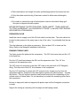
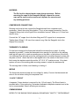
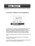
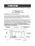
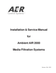
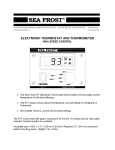
372 ROUTE 4 BARRINGTON, NH 03825 USA
TEL (603) 868-5720
FAX (603) 868-1040
E-Mail:[email protected]
1-800-435-6708
www.seafrost.com
SEA FROST SHORE ASSIST SA-1 134a
THIS MANUAL IS SUPPLEMENTAL TO
THE SEA FROST R-134a ENGINE DRIVE MANUAL.
INSTALLATION INSTRUCTIONS
CONDENSING UNIT LOCATION AND MOUNTING
The design of the Shore Assist allows placement of the air-cooled unit in an enclosed
space such as a cabin locker, sail locker or engine room. Intake air should be drawn in
from the cabin area to insure the coolest, driest air supply. Standard 4" duct hose may
be used. Discharge does not need ducting if a vent in the area allows warm air to
escape. Intake ducting from the exterior of the boat will cause damp salt air to be drawn
in reducing unit life. This will also increase below deck moisture. The SA-I is extremely
quiet.
An unducted SA-I in a poorly ventilated small space will heat the air,
lowering the capacity of the unit and possibly causing damage by
overheating the compressor.
Service access and installation requires that the front and left end (inlet/outlet side) be
exposed. The duct hose will require 4 inches of clearance past the end of the SA-I.
Mount the Shore Assist level. The compressor is at the bottom. The unit may be
bulkhead or platform mounted. Pilot holes have been predrilled for the # 8 x 3/8" selftaping screws and aluminum angle clips, included with the system.
INSTALLATION REQUIREMENTS
Neither inlet nor outlet should ever be blocked.
Provide for driest, coolest air for intake (top air port on housing.)
1
Total combined air duct length for intake and discharge should not exceed six feet.
Only the intake needs ducting if the area is vented to allow warm discharge to
escape.
For intake or exhaust through a finished panel order an extra black flange grill.
One part is shipped with each system.
BEFORE BEGINNING THIS SECTION READ; "WORK HABITS", "TUBE HANDLING",
"CUTTING and BENDING", and "SWAGELOK FITTINGS", in the SEA FROST ENGINE
DRIVE INSTALLATION MANUAL.
EXPANSION VALVE
Install the valve to supply one of the 3/8-inch tubes from the plate. The valve should be
located to allow access to the screw cap on top of the valve. It is preferable that the cap
be up.
Trim the tube ends on the plate as necessary. Allow at least 3/4" to insert into the
fitting. Refer to the Swagelok installation instructions.
RUNNING TUBING LINES
Two lines connect the plate and the compressor. The 3/8" is the return line and the 1/4"
is the liquid line.
Run the 1/4" liquid line between the SA-I and the expansion valve. This 1/4" line
connects to the expansion valve.
The 3/8" return line connects to the other 3/8" tube on the plate with a 3/8" Swagelok
fitting. The other end of this 3/8" line connects to the compressor.
Run the 1/4" liquid line in contact with 3/8" suction line for at least one foot from the
refrigerated cabinet. Wrap these two tubes tightly together with electrical tape. Insulate
this section. This will improve operation and prevent moisture from condensing on the
coldest section of these tubes. It is not necessary to insulate the remaining return line to
the compressor.
Be sure to keep each tube end capped with plastic caps until the Swagelok connection
is made.
Support the tubing as necessary with tie wraps and self-taping screws.
2
WARNING:
The SA-I unit is shipped under some nitrogen pressure. Before
removing the caps on the Swagelok fittings, remove the screw
caps on the service valve covers and depress the cores to vent
any existing pressure.
COMPRESSOR CONNECTIONS
Working one line at a time, remove the Swagelok caps from compressor and
condenser. Attach the union fitting bodies. This is a pre-swaged connection; See the
Swagelok fittings text in the Engine Drive installation manual. Make up is 1/4 turn from
wrench snug.
Connect the 1/4" copper line to the drier fitting and 3/8" copper line to compressor.
Tighten these fittings 1-1/4 turns from wrench snug. See the Swagelok text in the
Engine Drive manual.
THERMOSTAT & WIRING
For the best looking job the thermostat should be recessed into a panel. A cutting
template is provided. Locate the thermostat close enough for the bulb on the sensing
tube (pig tail type coil) to reach a mounting ear on the plate, or the bottom of the block.
It is necessary that the bulb end of the sensing tube be in excellent thermal contact with
the plate or block. Attach the bulb to the tapped hole in the center of the bottom of the
block using the stainless steel clip and the 1/4"-20 X 1/2" machine screw. On a plate
system use one of the existing plate mounting screws to attach the stainless clip.
The sensing tube is hollow; avoid bending or kinking it.
WIRING
The thermostat electrical leads are low voltage for safety. Connect the thermostat red
wires to the red wires exiting the compressor unit.
110-VOLT CIRCUIT
A separate 15-amp breaker is required for the 110-volt supply. The Shore Assist is
provided with a 3 wire male plug. A standard dedicated receptacle mounted next to the
unit is recommended. Secure all wiring as necessary.
COMMISSIONING
REFER TO THE ENGINE DRIVE MANUAL REGARDING, "SAFETY", "REFRIGERANT
3
HANDLING", "PROCEDURES FOR WORKING WITH R-134a".
Attach clean, purged gauges to the suction service port on the compressor. This is the
blue capped tube stub. It is not necessary to connect to the high-pressure port when
starting a new system. This is provided to aid in fault diagnosis. Evacuate the system
and perform the "Evacuation Leak Check" and "Leak Check" as in the "R-134A Engine
Drive Manual".
CHECK FOR LEAKS
Refer to the R-134a Engine Drive instruction manual: Refrigerant Handling and Leak
Checking sections.
CHARGE
The SA-I is charged with 134-a refrigerant. The maximum charge amount is 12oz.
This may be liquid-fed into the low side after evacuation, before the compressor is
operated. An automatic expansion valve regulates the evaporator pressure. This valve
is adjusted to maintain a constant evaporator pressure. The proper charge must be
added before the valve can be accurately set.
IMPORTANT NOTE ON THE SA-I 134A COMPRESSOR: The compressor, once
started, should not be stopped. If power is interrupted, the solid state starting device
has to cool before it will restart. Turn off the thermostat or disconnect the power line for
fifteen minutes or more before restarting. If the pressures in the system are not
equalized the unit will not start. This means the high and low pressure must be the
same. If accidental interruption of the line while commissioning occurs the gauge set
may be used to balance the system. To balance the system, install the gauges on both
service ports. Cap off the center port after purging the port or hose. Slowly open the
gauge valves. Both gauges should read the same pressure. Close the gauge valves
and proceed.
ADJUSTING THE VALVE
Before operating the compressor, unscrew the plastic cover on the valve body. Note
the adjusting knob. Counter-clockwise rotation decreases the pressure. Clockwise
rotation increases the pressure. One turn should equal a 2 psi pressure change.
Check that the valve is set with the last groove even with the end of the valve body.
Start the compressor. The valve must be adjusted to a 0 to 2 psi reading on the low
side gauge port. Be sure your gauge is set at O before hook-up. Allow several minutes
between each adjustment. Moisture may form on the adjusting knob side of the valve
and freeze causing the valve to malfunction. To prevent this replace the cap after each
4
adjustment. Be sure valve is dry before final cap replacement. Operate for 30 minutes
to confirm proper valve setting and operation.
The valve may need to be cleared of dirt or chips if adjustment is not possible. With the
compressor running, turn the valve adjustment knob clockwise about 3 turns
momentarily then back to the proper setting. Do not leave the valve in the open position
allowing high backpressure, as this may cause the compressor to overload.
After satisfactory adjustment, turn off the thermostat and remove the gauges. Recap the
service ports and replace the SA-I cover. When the valve has dried, insulate the valve
body by cutting the insulating sleeve to fit the valve then wrap with cork tape to prevent
condensation. Insulate the one-foot section of 3/8" tubing that exits the refrigerated
cabinet. The valve need not be insulated if it is in the icebox.
Troubleshooting note: The operating pressure of the system will not indicate the
amount of refrigerant in the system. The valve will not give proper operation or
pressure if it is undercharged. Check the valve scribe line. It should correlate with the
low side gauge pressure.
The system requires enough refrigerant to supply liquid to the valve. If the valve has a
steady hissing sound then the charge is ok. If the valve is sputtering then it is low. If
the valve is making a noticeable roar it is empty. If the low side pressure is properly set
5
the high side pressure will be 80 to 135 psi depending on the air temperature (50 to 95
degrees F.) through the unit. Almost immediately upon start up the valve body will begin
to frost.
THE THERMOSTAT
The Shore Assist thermostat is variable. Turning the knob fully counterclockwise turns
the unit "OFF". The one snowflake position is the warmest setting. The fully clockwise
setting at three snowflakes is the coldest. The thermostat may be adjusted to obtain any
temperature desired in the cabinet and may be calibrated should the warmest setting be
too cold.
OPERATION DESCRIPTION
The SEA FROST Shore Assist SA-I is a small system. It is efficient in its electrical
conversion of energy to heat movement. Its rate of cooling is 1/20 the rate of the Engine
Drive system. By being small it is quiet, compact, has low electrical starting
requirements and running power draw and is able to be air-cooled. The SA-I will
operate in up to 120 degrees of ambient air temperature. Because of its size it will
operate 80 percent of the time in warm climates. The unit will freeze the holdover plate
from warm but may take all day. If rapid cooling of the system is needed operate the
Engine Drive to bring the system to its cooling temperature then let the SA-I take over.
The unit will automatically operate if the thermostat, and proper panel switch is on and
shore power is available. The system may be operated using the proper sized DC to
AC inverter. The Shore Assist and the Engine Drive are separate units and may be
operated simultaneously. Both units are controlled by separate controls.
DEFROSTING
The plate will require defrosting from time to time as the frost layer builds.
Allowing the plate to warm above freezing is one method of defrosting. Warm water or
a hair dryer is also a quick method. The SEA FROST plates can be scraped with a
spatula or ice scraper to remove excessive frost build up.
OPERATION INSPECTION
Within a few minutes of starting the Shore Assist the tubing in close proximity to the
valve and the valve itself will be noticeably cold. If after 20 minutes of operation cooling
in this area is not observed do not continue to operate the system.
6
7
THERMOSTAT CALIBRATION INSTRUCTIONS
Note: Be sure that the unit is operating properly before making any thermostat
adjustments. The sensing bulb must be in excellent thermal contact with the plate or
block.
The range of this control may be changed. To access the adjustment screw, remove
the four mounting screws on the thermostat panel. Tip the panel forward and remove
the protective tape to expose a slot in the case. Make the adjustment with a torx or
small phillips head screwdriver.
Make small adjustments. Record all adjustments.
If the lowest setting on the thermostat panel (1-snowflake) is too cold:
•
Turn the adjustment screw clockwise. One 360-degree turn will raise the box
temperature approximately 6 degrees f.
If the highest setting on the thermostat panel (3-snowflakes) is too warm:
•
Turn the adjustment screw counterclockwise.
8
HOLDOVER PLATES
STAINLESS
STEEL
EVAPORATOR
PLATES
9