1
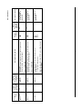
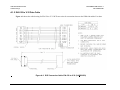
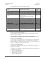
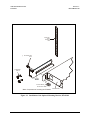
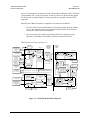
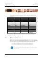
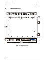
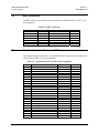
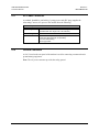
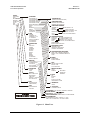
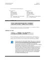
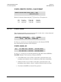
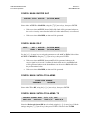
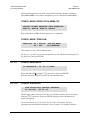
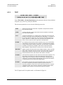
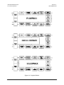
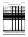
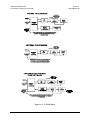
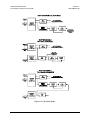
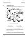
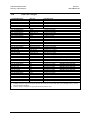
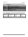
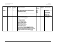
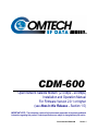
CDM-600 Satellite Modem
Physical Description
4.3
Revision 7
MN/CDM600.IOM
Rear Panel
Figure 4-2. Rear Panel
External cables are attached to connectors on the rear panel of the CDM-600. These
comprise:
Name
Rx IF
Tx IF
Aux Serial
Overhead
Data Interface
External Reference
Audio
Remote Control
IDR Alarm
Alarms
Balanced G.703
IDI
DDO
Rx Unbalanced
Tx Unbalanced
External Frequency Ref
Ref Des
J1
J2
P6
P3A
P3B
J9
P4A
P4B
P5A
P5B
P7
J10A
J11A
J10B
J11B
J12
Connector Type
BNC
BNC
He1402 3 pin header
25-pin D (male)
25-pin D (female)
BNC
9-pin D (female)
9-pin D (male)
15-pin D (female)
15-pin D (male)
15-pin D (female)
BNC
BNC
BNC
BNC
SMA
Function
RF Input
RF Output
Auxiliary Serial
Overhead Data
Data Input/Output
Input
Sound Input
Remote Interface
Alarm
FORM C Alarm
Balanced G.703 Data
Insert Data In
Drop Data Output
Receive G.703
Transmit G.703
External IF reference
Input (Optional)
Note: The European EMC Directive (EN55022, EN50082-1) requires using properly shielded
cables for DATA I/O. These cables must be double-shielded from end-to-end, ensuring a
continuous ground shield.
4.3.1
IEC Line Input Connector
The IEC line input connector contains the ON/OFF switch for the unit. It is also fitted
with two fuses - one each for line and neutral connections (or L1, L2, where appropriate).
These are contained within the body of the connector, behind a small plastic flap.
•
•
For 230 volt AC operation, use T0.75A, (slow-blow) 20mm fuses.
For 115 volt AC operation, use T1.25A, (slow-blow) 20mm fuses.
For continued operator safety, always replace the fuses with the correct
type and rating.
IMPORTANT
4–2