1
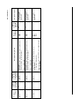
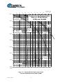
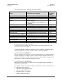
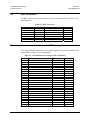
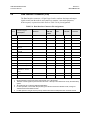
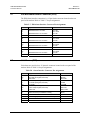
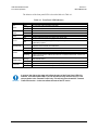
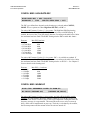
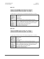
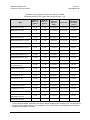
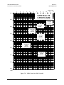
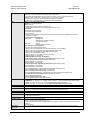
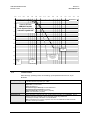
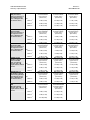
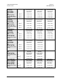
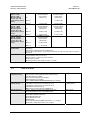
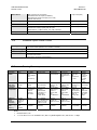
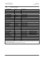
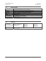
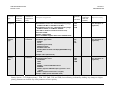
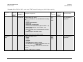
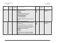
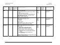
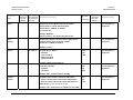
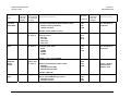
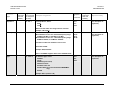
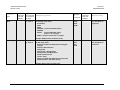
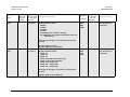
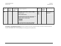
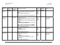
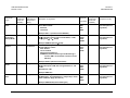
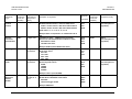
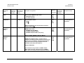
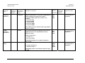
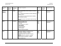
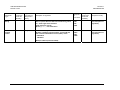
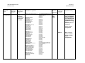
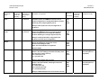
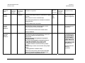
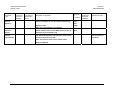
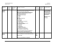
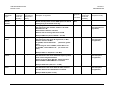
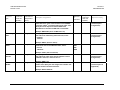
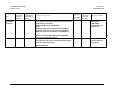
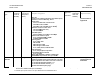
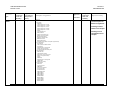
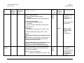
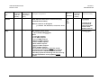
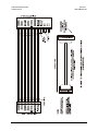
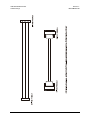
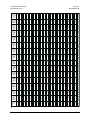
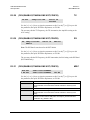
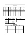
CDM-600 Satellite Modem
Connector Pinouts
5.4
Revision 7
MN/CDM600.IOM
Data Interface Connector (P3B)
The Data Interface connector, a 25-pin D type female, conducts data input and output
signals to and from the modem, and connects to customer’s terrestrial equipment,
breakout panel, or protection switch. Refer to Table 5-4 for pin assignments.
Table 5-4. Data Interface Connector Pin Assignments
Pin #
Generic Signal
description
Direction
EIA-422
EIA 530
LVDS
V.35
EIA-232
Circuit #
2
Transmit Data A
DTE to Modem
SD A
SD A
BA
103
14
Transmit Data B
DTE to Modem
SD B
SD B
-
103
24
Transmit Clock A
DTE to Modem
TT A
SCTE A
DA
113
11
Transmit Clock B
DTE to Modem
TT B
SCTE B
-
113
15
Modem to DTE
ST A
SCT A
DB
114
Modem to DTE
ST B
SCT B
-
114
3
Internal Transmit
Clock A
Internal Transmit
Clock B
Receive Data A
Modem to DTE
RD A
RD A
BB
104
16
Receive Data B
Modem to DTE
RD B
RD B
-
104
17
Receive Clock A
Modem to DTE
RT A
SCR A
DD
115
9
Receive Clock B
Modem to DTE
RT B
SCR B
-
115
8
Receiver Ready A
Modem to DTE
RR A
RLSD *
CF
109
10
Receiver Ready B
Modem to DTE
RR B
-
-
109
23
DTE to Modem
-
-
-
-
7
External Carrier Off
(EIA-232 ‘1' or TTL
‘low’ )
Signal Ground
-
SG
SG
AB
102
1
Shield
-
Shield
FG
AN
101
12
Notes:
1. Receiver Ready is an EIA-232 -level control signal on a V.35 interface.
2. DO NOT connect signals to pins which are not shown - these pins are reserved for use by the redundancy
system.
3. ‘B’ signal lines are not used for EIA-232 applications.
4. For X.21 operation, use the EIA-422 pins, but ignore Receive Clock if the Modem is DTE, and ignore
Transmit clocks if the Modem is DCE.
5. For IDR operation using G.703, this primary interface becomes the 8 kbps EIA-422 overhead channel.
5–3