1
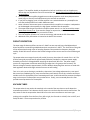
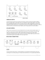
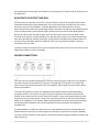
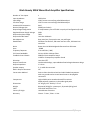
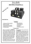
BLACK BEAUTY 305 WATT VACUUM TUBE AMPLIFIER
This manual provides general, ongoing use and safety information of the Black Beauty 305 (VTA305M)
Mono Block Amplifier.
General
The new series of mono block amplifiers are the perfect blend of form and function and the ideal choice
for serious music listeners. The Black Beauty is conservatively rated at 305 Watts rms into 8 ohms and
was designed to drive the most demanding speakers. These amplifiers offer extreme performance that is
difficult to believe, and each amplifier features a high impedance input, an automatic DC restorer circuit,
a “set and forget” bias adjustment, and low idle current which greatly increases output tube life. They
have ultra-wide bandwidth output transformers with interleaved windings capable of the most nuanced
voice as well as huge peak output capacity. Selectable feedback control allows the user to change the
sound of the amplifier from vintage classical to modern contemporary.
From a listening perspective these amplifiers provide a warm, rich sound with a sumptuous and
enveloping sound stage, a great front to back depth of field, and very tight, pin-point imaging within that
larger acoustic. A special current feedback circuit allows the amplifier to “listen to the room” via
feedback from the speakers acting as microphones (using the law of reciprocity). The room-speakeramplifier interaction provides a sense of believable ambience and acoustic space that is thoroughly
realistic and quite enjoyable. Additionally, the transformer output impedance allows the signal to follow
the impedance curve of the speaker system, allowing more voltage to be delivered to the loudspeaker at
very low frequencies – providing an exceptional and satisfying low end response.
Safe Operating Conditions
Because of the high power available it is necessary to emphasize some prudent and safe operating
conditions.
1. Be cautious when lifting the amplifier. It weighs 42 pounds. Make certain that what it is placed
on can support the weight.
2. The amplifier should be situated so that its location or position does not interfere with its
proper ventilation. The amplifier should never be placed near or over a radiator or heat
1|Page
3.
4.
5.
6.
7.
8.
register. The amplifier should not be placed in a built-in installation such as a bookcase or
cabinet that may impede the flow of air around the unit. Do not place this amplifier directly on
carpeted floors.
Do not operate the amplifier plugged into an ordinary extension cord. Heavy duty extension
cords (14 ga. or heavier) have adequate wire size and will not overheat.
If you plan on plugging a pair of these amplifier into a switched outlet on a preamplifier be
sure that preamp outlets can handle 1500 watts total.
Never connect or disconnect inputs or outputs while the amplifier is turned on. Loudspeakers
can be damaged or destroyed by the high power available from the amplifier.
The output tubes do get hot when the amplifier power switch is on. Do not touch the output
tubes when the unit is on. If you need to change an output tube, wait 10 minutes after
powering the unit down before you touch the tubes.
Turn the amplifier off when not in use to save energy and extend the life of the tubes.
Additional safety information is located at the back of this manual.
CIRCUIT DESCRIPTION
The input stage of these amplifiers consists of a 12AX7 current sourced, long-tailed balanced pair
direct coupled to a second long-tailed balanced pair comprised of a 12AT7. The 12AT7 drives the grids
of the output tubes through a pair of coupling capacitors that provide low frequency loop-gain
stability. A 6AL5 DC restorer ensures that the bias voltage remains correct over the entire audio signal
cycle.
The output tubes are arranged in push pull parallel, three up, three down for a total of six in all. The
KT120 screen grids are operated at approximately 390 volts provided by a separate power supply
formed by one-half of a voltage doubler supplying the plates with 785 volts. The power supply
consists of a large power transformer with energy storage that is far greater than necessary. AC
filament voltage is biased to approximately 70 volts. Multiple decoupling filter sections are used with
load regulation obtained through resistive constant current loading.
Turn-on in-rush current limiting is provided by a thermistor, bias voltage adjustment by a rear panel
bias control pot, feedback gain by a top-mounted front panel switch, volume by a volume control pot
and bias current is displayed by a front mounted panel meter. A tube cathode fuse protects the output
stage in the event of a catastrophic vacuum tube failure. Finally, a rear mounted power line fuse
provides overall protection for the amplifier.
VACUUM TUBES
The output tubes do not need to be matched, as the sound of the amp does not at all depend on
matched output tubes. That's because the DC restorer circuit eliminates the need to match tubes. The
only caveat is that the output tubes should all be from the same manufacturer and same type.
Looking at the amplifier from the front, from left to right, the first tube is a 12AX7, then a 12AT7, and
finally the 6AL5. The six output tubes are; KT120s.
2|Page
FEEDBACK SWITCH
The small switch mounted on the top front of the chassis controls the amount of negative feedback.
When the toggle handle is pushed LEFT (classic), the feedback is approximately 20 dB, a value used by
most vintage amplifier designers and is my personal preference. When toggled RIGHT (contemporary),
feedback is limited to about 11 dB. This represents the practice of many modern day designers. Please try
it both and make your own determination based on your listening experience and your speakers.
VOLUME CONTROL
Under normal circumstances, this control should be left in the maximum (fully clockwise) position. If
you have a noisy preamp, turning it halfway down and centering it at the 12:00 o'clock position will
reduce the preamp noise by half, or 6 dB. It should always be turned all the way down when
connecting or disconnecting any input or output in your system. The RCA audio input jack should be
used to feed the signal into the amplifier from your signal source.
REAR PANEL CONNECTIONS
FUSES
The rear panel IEC socket fuse is a 6 amp fast blow fuse, and should be replaced with the same type
and rating if it ever needs replacing. The vacuum tube cathode fuse is a 1.5 amp fast blow and should
3|Page
be replaced with the same type. Do not under any circumstances use "slow-blo" fuses. Both fuses are
fast blow fuses.
ADJUSTING THE OUTPUT TUBE BIAS
The front panel incorporates a bias meter. Turn the volume control all the way down (full counter
clockwise) while performing bias adjustments. Use a small screwdriver and adjust the bias control
(located on the rear of the amplifier, “Tube Bias Adjustment”) for 100 mA after the unit has
warmed-up for 20 minutes. The normal range setting is from 60 mA to 150 mA, and changes here will
vary the damping factor of the amplifier slightly. More bias current increases the damping factor,
whereas less bias current provides a softer more tube-like sound. The bias current design center
should be set to 100 mA, and that should be your starting reference point if you want to experiment
from there with different settings. Personally, I preferred the sound best on my speakers when I set
the bias current to between 80 mA and 100 mA. It will vary from speaker to speaker, and more
importantly with your taste.
The meter reads the combined current for all six output tubes, and it is normal for this current to vary
slightly with changes in power line voltage.
SPEAKER CONNECTIONS
From the rear view, the black binding post is common, and (moving to the right) the next red post is
two ohms, then four ohms, and the far right post is for eight ohms. The power curve is quite flat,
hence the two ohm tap may be used for one ohm speakers, and the eight ohm tap may be used for
sixteen ohm speakers.
To connect the speaker first check the impedance of the speaker which is usually identified on
the speaker itself or in the owner's manual. Connect one lead from the common terminal of the
speaker to the common terminal on the back of the amplifier. Connect the positive lead on the red
terminal on the back of the speaker to one of the red output terminals on the back of the amplifier
based on the impedance of the speaker. When multiple speakers are to be connected to the output,
the combined load impedance must be calculated and the load connected to the appropriate
impedance tap.
If a load impedance is used that is lower than the output impedance tap, then reduced power and
possible distortion will result. If a load impedance is used that is higher than the output impedance
tap, then neither the signal nor the amplifier will be harmed but the voltage available is limited to that
stated at that tap.
4|Page
POWER SWITCH
Up is on, down is off. There is no power-on indicator except for the glow of the tubes; you will have to
remember whether you turned it on until you can see the tubes glow. It is safe to switch the amplifier
on and off at will.
LINE VOLTAGE
This amplifier is configured for operation with 120V 60 Hz.
COOLING
Convection cooling - Cool air is drawn from under the chassis by the heat from the tubes acting as an
air pump, and exhausting the warm air out the chassis through the top vents. Do not place the
amplifier on a carpet or in a closed cabinet. You must allow the feet to do their job by keeping the
bottom raised, allowing unimpeded airflow.
MONITORING
Once the bias has been set, it will normally not need to be adjusted for several years unless you want
to experiment for different sound. Or if you install replacement output tubes, or the amplifier
suddenly starts to sound funny. If you hear a POP and see a flash, yet the amp continues to play, you
should first check the current by looking at the front panel meter, and then the 1.5A output tube fuse.
Remember that if either of the fuses blow, the output current will drop to zero. If the TUBE fuse
blows, replace it WITHOUT replacing any tubes. Turn the amp on and monitor the current. If it climbs
to within the range you had set, and if the amp sounds good, all is well.
Often an output tube has a spec of dust-like impurity, which comes into contact with an internal
element, shorts the element and gets itself vaporized into gaseous oblivion. The getter, the mirror-like
shiny plating on the inside of the tube does its job, absorbs the vaporized material and the tube is like
new again. All it takes is a new fuse.
If you install a new fuse and it blows again, you will need to determine which tube is the culprit.
Proceed as follows: turn the amplifier off and allow hot tubes to cool, remove all 6 of the output tubes
and turn the volume control all the way down (full counter clockwise). Turn the amp on and LEAVE IT
ON. While monitoring the bias current by watching the meter, put a tube into socket number six (the
far right front socket). Allow 60 seconds for the tube to warm up. If the bias current comes up to
about one sixth the normal amount, the tube is good. Remove the tube - you can do it with your bare
fingers, as one minute is not long enough for it to get too hot to hold - and install another tube, also in
socket six. Replace one-by-one, until a fuse blows or one of the tubes does not show a bias current.
Replacement tubes are available for free from the Bob Carver factory if one blows under the one year
tube warranty period. If a tube blows beyond the warranty period we recommend you purchase a
replacement from us as we purchase large amounts of tubes and provide a very competitive price for
a tested, known good tube from our preferred tube supplier.
5|Page
TUBE TESTER
The front panel meter may be used to test the tubes. Remove all the large power output tubes; plug
the amp into the AC wall socket with the main rear panel power switch OFF. Insert the tube you wish
to test into socket #6 (the far right front socket). Turn the bias control fully clockwise and turn the
main power switch ON. With a watch, time the warm-up period for exactly one minute and note the
current reading. Turn the amplifier OFF, remove the tube and insert the next one. You can hold the
tube with your bare fingers - it will not be too hot after only a minute, provided it was cool at the
start. Keep track of each reading, and repeat until all tubes have been checked. If any one tube does
not bias up or “runs away” with its current climbing substantially higher ~ 200% than the others, then
it must be replaced. It is okay to turn the amp on and off at will. Return the bias control to its original
position and put all the tubes back into their sockets. This completes the tube testing operation.
MATCHING OUTPUT TUBES
Matching output tubes is not necessary, thanks to the DC restorer. But it’s fun to do anyway. Test each
tube as noted above, but write down the current on each tube one at a time. You will end up with six
numbers. The goal is to select two groups of three whose sum (from any three tubes) is as close as you
can get to a similar sum from the other group of three tubes. When you are finished determing the
the two groups, add up the current in each group and check that they are as close as you can get
them. This is a bit of trial and error; while you have them on the table in front of you and are adding
the currents up, you may have to switch a tube or two from one group to the other to get the closest
sums. Then install the first group in sockets #1, #3, #5, the odd sockets. Install the other group into
sockets #2, #4, #6, the even sockets. The socket positions on the amp are, from left to right, looking
from the front. 1,2,3,4. The last two positions 5, 6, are the front tubes on the right. The front left
tube is #5, then #6 is to its right.
SMALL TOGGLE SWITCH
There is one toggle switch on the top front. It controls the feedback as mentioned earlier. Thrown left
is classical, right is contemporary.
NEW AMPLIFIER SMELL
Like a brand new car, this amplifier possesses a "new amplifier smell". When powered up for the first
time, the fresh paint and recent skin oils on the tubes will create a new hot amp smell. It will dissipate
with use, usually requiring about six weeks of normal operation.
6|Page
Black Beauty 305W Mono Block Amplifier Specifications
Number of Line Inputs
Input impedance
Input Stage
Pre-driver Stage
Automatic DC Restoration
Nominal Voltage Gain
Output Stage Configuration
Regulated Screen Supply Voltage
Output tube plate voltage
Output tube Idle Power
Bias Adjustment
Rated Power
Noise
Hum
Frequency Response
Full Power Bandwidth
Feedback Control Switch
Distortion
Output Transformer
Output Impedance
Speaker outputs
Built in Output Tube tester
Construction Method
Components
Dimensions
Weight
Color
Country of Origin:
Warranty:
1
100 k ohms
12AX7 current sourced long tailed balanced pair
12AT7 current sourced long tailed balanced pair
6AL5
30 dB (into 8 ohms)
3 complimentary sets of KT120s in a push pull configuration (6 total)
390V
785V
Less than 14W each
Rear panel pot, front panel meter, set and forget
305 watts into 8 ohms, 330 watts into four ohms, 290 watts into
two ohms
Better than 110 dB A Weighted referenced into 305 watts
-100dB
2 Hz to 85 kHz. (-3dB)
24 Hz to 28 kHz. Without filters
20dB for Classic Amplifier Sound
11 dB for Contemporary Amplifier Sound
Less than 0.5%
Interleaved windings, super wideband low leakage inductance design
1.3 ohms
2, 4, and 8 ohm terminals
Yes
Point-to-Point hand wired axial and radial leaded components
with star grounds and no circuit board traces or de-plugable
connectors.
High reliability wire wound and metal film resistors
Metal polyester capacitors in the audio signal paths
14” long by 12.5” wide by 7.2” tall
84 pounds (38 kg) for a stereo pair, 42 pounds (19 kg) each
Gloss black with Silver Trim
United States of America
Chassis - 7 Years, Tubes – 1 Year
7|Page
Safety Information
IMPORTANT SAFETY INFORMATION
Read Information — All the safety and operating information should be read before the amplifier
is plugged in.
Follow Information — All operating and use information should be followed.
Retain Information — Retain the safety and operating information for future reference.
Heed Warnings — All warnings on the amplifier & in the operating instructions should be heeded.
Ventilation — The amplifier should be situated so that its location or position does not interfere
with its proper ventilation. The amplifier should never be placed near or over a radiator or heat
register. The amplifier should not be placed in a built-in installation such as a bookcase or cabinet
that may impede the flow of air through the ventilation openings. Do not place this amplifier
directly on carpeted floors.
Non-Use Periods — Amplifiers that are left unattended should be turned off via the rear panel
switch to extend the life of the tubes and conserve energy.
Grounding or Polarization — Do not defeat the safety purpose of the polarized or grounding-type
plug. A polarized plug has two blades with one blade wider than the other blade. A grounding
type plug has two blades and a third grounding prong. The polarized wide blade and the third
prong are provided for your safety. If the provided plug does not fit your outlet, consult an
electrician for replacement of the obsolete outlet.
Power Cord Protection — Protect the power cord from being walked on or pinched particularly at
plugs, convenience receptacles and the point where they exit from the amplifier.
Water— Do not use the amplifier near water.
Cleaning — Unplug the amplifier from the AC outlet before cleaning. Use only a dry cloth to clean.
Object and Liquid Entry — Never insert objects of any kind through the openings of these
amplifiers, as they may touch dangerous voltage points or short-out parts that could result in a fire
or electric shock. Care should be taken so that objects do not fall and liquids are not spilled into
the amplifier through openings in the enclosure.
Servicing — Do not attempt to service these amplifiers yourself, as opening or removing the
bottom cover WILL expose you to dangerous high voltages. Refer all servicing to Bob Carver LLC.
Damage Requiring Service — These Amplifiers should be serviced by Bob Carver LLC when:
A power supply connection or a plug has been damaged or
If liquid has been spilled into the amplifier or objects have fallen into the amplifier or
The amplifier has been exposed to water or moisture or
The amplifier does not appear to operate normally or exhibits a marked change in
performance or
The amplifier has been dropped or the enclosure damaged.
8|Page
Replacement Parts — When replacement parts are required, be sure the service technician has
used replacement parts specified by the manufacturer or that have the same characteristics as the
original part. Unauthorized substitutions may result in fire, electric shock, or other hazards.
Safety Check — Upon completion of any service or repairs to this audio product, ask the service
technician to perform safety checks to determine that the audio product is in proper operating
condition.
Lightning Storms — Unplug this amplifier during lightning storms or when unused for long periods
CAUTION: - Changes or modifications not expressly approved by BOB CARVER LLC will void the
manufacturer’s warranty.
9|Page
WARRANTIES:
Bob Carver LLC warrants that all equipment manufactured by us to be free from defects in materials
and workmanship for seven (7) years (vacuum tubes – one (1) year).
This warranty shall not apply (a) to equipment not manufactured by Bob Carver LLC (b) to
equipment which has been repaired or altered by someone other than Bob Carver LLC (c) to
equipment which shall have been subjected to negligence, accident, misuse, abuse, or damage by
circumstances beyond Bob Carver LLC’s control, or due to improper operation, maintenance or
storage, or to other than normal use or service.
The foregoing warranties do not cover reimbursement for labor, transportation, removal,
installation, replacement cartons or other expenses which may be incurred by the dealer in
connection with repair or replacement.
If you have any questions concerning the operation or maintenance of this equipment, please contact:
CUSTOMER SERVICE
Bob Carver LLC.
157 Venture Court, Suite 12
Lexington, KY 40356
(859) 258 – 9794
[email protected]
10 | P a g e