1
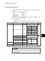
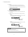
7 TRANSMISSION MODULE
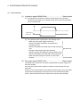
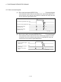
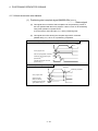
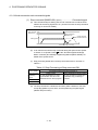
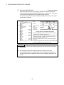
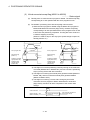
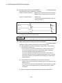
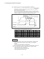
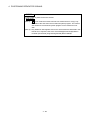
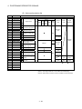
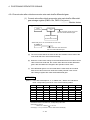
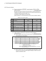
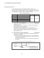
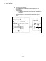
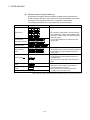
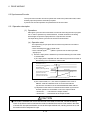
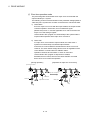
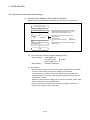
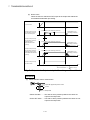
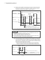
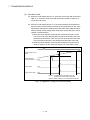
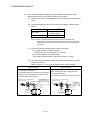
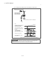
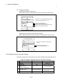
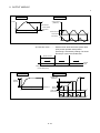
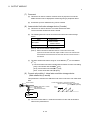
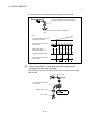
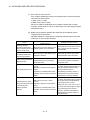
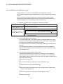
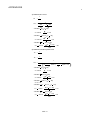
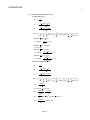
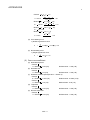
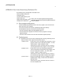
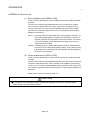
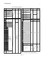
(d) The current value of input axis (synchronous encoder) changes at the clutch
ON state only.
Input pulse from
synchronous encoder
ON
OFF
Clutch ON/OFF
command device (Note)
Clutch status signal
ON
ON
OFF
ON
OFF
External input
(TREN signal)
1 operation cycle
required
2 operation cycle
required
Current value of
input axis
(Synchronous encoder)
Continuance from the
current value at the
clutch OFF
Current value of
output axis
Clutch OFF state
Clutch ON state
Clutch OFF state
(Note) : Refer to Section "7.2.2 Parameters" for details.
Fig. 7.6 Operation Timing for External Input Mode
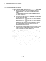
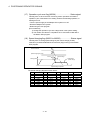
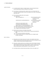
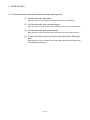
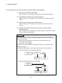
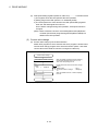
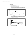
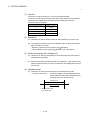
(e) Only axis that the incremental synchronous encoder (manual pulse
generator) is set as drive module can be used in this mode. When an
absolute synchronous encoder is set as the drive module, it cannot be used.
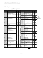
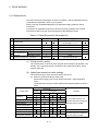
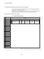
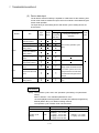
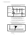
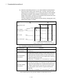
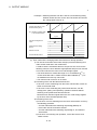
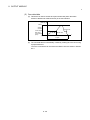
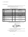
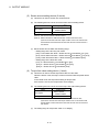
(f) A synchronous encoder, external input and external input mode clutch can
be set in only 1:1 ratio.
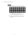
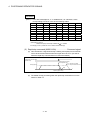
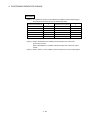
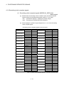
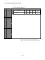
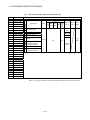
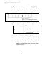
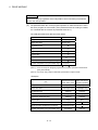
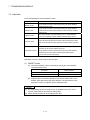
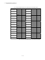
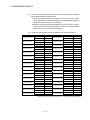
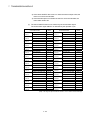
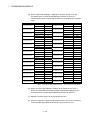
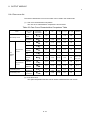
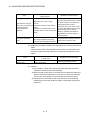
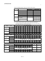
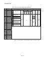
The relationship between the synchronous encoder and external input is
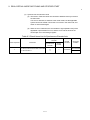
shown in the table below.
Synchronous
External input
Synchronous
External input
encoder No.
(TREN signal)
encoder No.
(TREN signal)
P1/E1
TREN 1
P7/E7
TREN 7
P2/E2
TREN 2
P8/E8
TREN 8
P3/E3
TREN 3
P9/E9
TREN 9
P4/E4
TREN 4
P10/E10
TREN 10
P5/E5
TREN 5
P11/E11
TREN 11
P6/E6
TREN 6
P12/E12
TREN 12
(Note) : The range of synchronous encoder No. P1/E1 to P8/E8 is valid in the Q172CPU(N).
7 - 25