1
8 OUTPUT MODULE
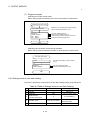
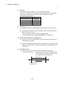
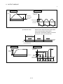
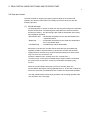
8.4.3 Parameter list
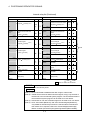
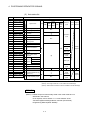
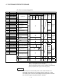
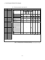
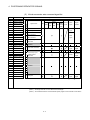
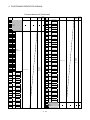
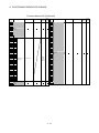
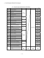
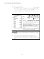
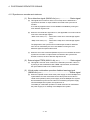
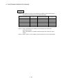
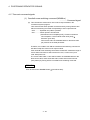
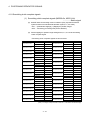
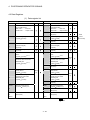
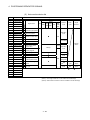
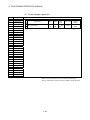
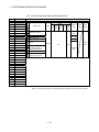
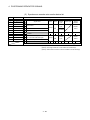
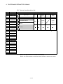
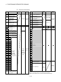
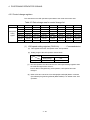
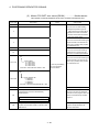
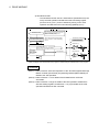
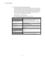
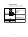
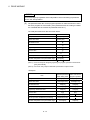
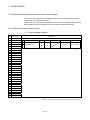
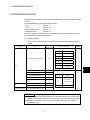
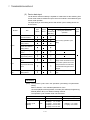
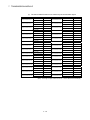
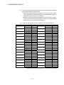
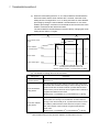
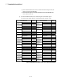
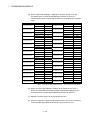
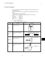
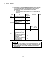
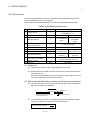
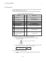
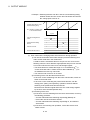
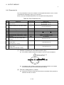
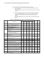
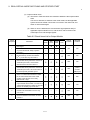
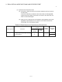
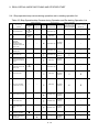
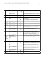
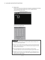
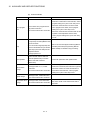
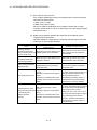
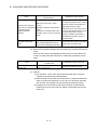
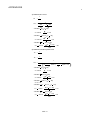
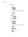
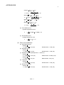
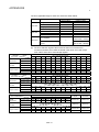
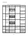
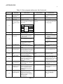
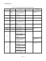
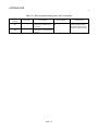
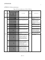
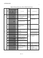
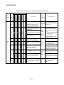
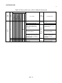
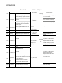
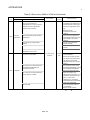
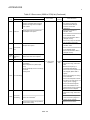
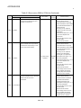
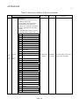
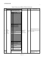
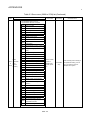
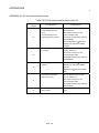
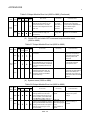
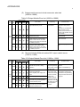
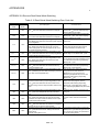
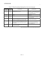
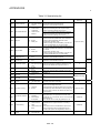
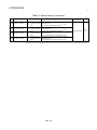
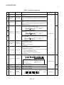
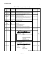
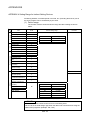
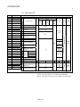
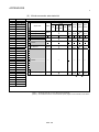
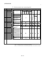
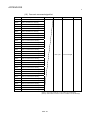
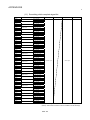
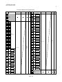
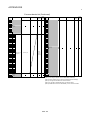
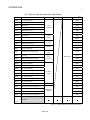
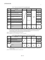
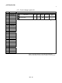
The cam parameters are shown in Table 8.5 and the parameters No.2 to No.11 shown
in this table are explained in items (1) to (10) below.
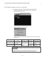
Refer to the help of SW6RN-GSV22P for the cam parameter setting method.
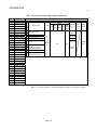
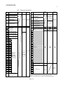
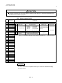
Table 8.5 Cam Parameter List
No.
1
2
Setting item
Output axis No.
Default value
Setting range
Q173CPU(N) : 1 to 32
0
Number of pulses per cam shaft revolution
(NC)
Q172CPU(N) : 1 to 8
0
1 to 1073741824 [PLS]
—
Word device (D, W)
65535
1 to 65535 [PLS]
3
Cam No. setting device (1 word)
4
Permissible droop pulse value
5
Output unit
6
Stroke amount setting device (2 words)
—
Word device (D, W)
7
Torque limit value setting device (1 word)
—
-(300[%]) / word device (D, W)
8
Comment
None
32 characters
—
Word device (D, W)
—
- / word device (D, W)
—
- / word device (D, W)
9
mm
Lower stroke limit value storage device
(2 words)
mm
inch
PLS
Current value within 1 virtual axis revolution
10
storage device
(Main shaft side, 2 words)
Current value within 1 virtual axis revolution
11
storage device
(Auxiliary input axis side, 2 words)
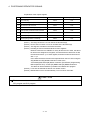
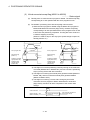
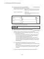
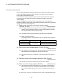
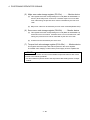
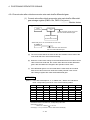
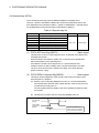
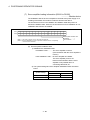
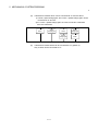
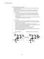
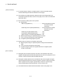
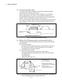
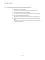
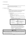
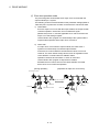
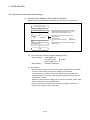
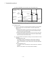
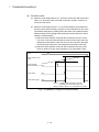
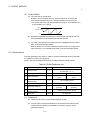
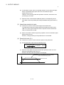
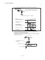
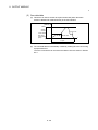
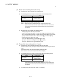
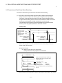
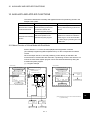
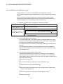
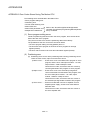
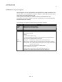
(1) Number of pulses per cam shaft revolution (Nc)
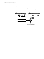
(a) The number of pulses required to rotate the cam one cycle is displayed.
Number of pulses per cam
shaft revolution (Nc)
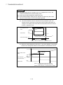
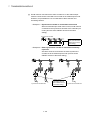
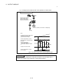
(b) The setting for the number of pulses per cam shaft revolution is not related
to the travel value per pulse (fixed parameter setting).
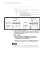
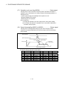
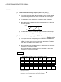
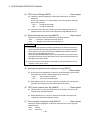
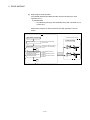
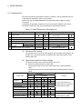
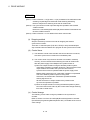
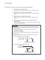
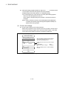
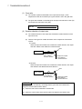
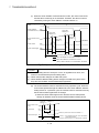
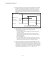
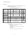
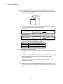
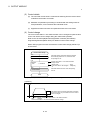
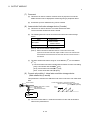
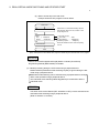
(2) Cam No. setting device (1 word)
(a) This device is used to set the device that sets in the Motion SFC program by
which the cam No. to control.
8 - 29