1
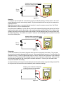
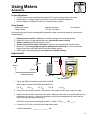
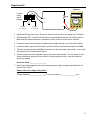
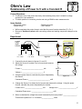
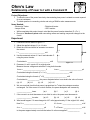
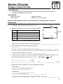
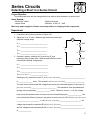
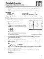
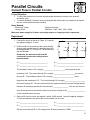
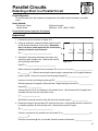
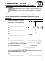
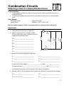
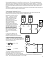
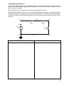
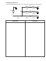
Parallel Circuits
Resistance in Parallel Circuits
Project Objective:
•
•
To verify that the total resistance in a parallel circuit is less than the least value resistance in
parallel.
To provide practice using parallel resistance formulas and confirming them through circuit
measurements.
Items Needed:
- Electronics Trainer
- Jumper Wires
- Digital multi-meter
- Resistors: 18kΩ, 100kΩ, 220kΩ & 3 - 10kΩ
When making resistance measurements, make sure there is no power applied to the circuit.
Experiment
1. Connect the circuit as shown in Figure 15-1.
2. Measure RT at points A and B.
RT = _______________________.
3. Calculate RT if a 10kΩ resistor were to be inserted
between points C and D. Use the product over sum
formula.
RT =
A
B
R1
10kΩ
E
C
R2
R3
D
F
R1 x R2
R1 + R2
Figure 15-1
RT calculated = _______________________.
When two equal resistors are connected in parallel,
the total resistance is equal to ________________________ the resistance of one branch.
4. After calculating RT, use an ohmmeter and measure at points A and B with a second 10kΩ
resistor inserted at points C and D.
RT measured = _______________________.
5. Calculate RT if a third 10kΩ resistor were to be inserted between points E and F. Use the
reciprocal formula.
1
RT =
1
1
1
RT calculated = _______________________.
+
+
R1
R3
R2
When three equal resistors are connected in parallel, the total resistance of the circuit is equal
to ________________________ the resistance of one branch.
6. After calculating RT, use the ohmmeter and measure at points A and B with a third 10kΩ
resistor inserted at points E and F.
RT measured = _______________________.
36