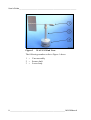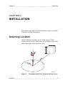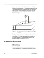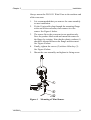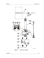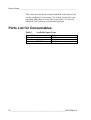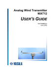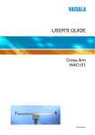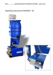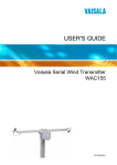
1
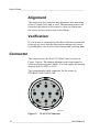
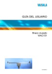
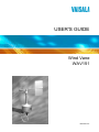
USER'S GUIDE
Wind Vane
WAV151
M210294en-A
PUBLISHED BY
Vaisala Oyj
P.O. Box 26
FIN-00421 Helsinki
Finland
Phone (int.):+358 9 8949 1
Fax:
+358 9 8949 2227
Visit our Internet pages at http://www.vaisala.com/
© Vaisala 2002
No part of this manual may be reproduced in any form or by any
means, electronic or mechanical (including photocopying), nor may its
contents be communicated to a third party without prior written
permission of the copyright holder.
The contents are subject to change without prior notice.
Please observe that this manual does not create any legally binding
obligations for Vaisala towards the customer or end user. All legally
binding commitments and agreements are included exclusively in the
applicable supply contract or Conditions of Sale.
___________________________________________________________________
Table of Contents
CHAPTER 1
GENERAL INFORMATION .......................................................3
About This Manual..................................................3
Contents of This Manual.......................................3
Version Information...............................................4
Related Manuals...................................................4
Safety .......................................................................4
General Safety Considerations.............................4
Product Related Safety Precautions .....................5
ESD Protection .....................................................5
Regulatory Compliances........................................6
Warranty ..................................................................6
CHAPTER 2
PRODUCT OVERVIEW.............................................................7
Introduction to WAV151 Wind Vane ......................7
CHAPTER 3
INSTALLATION ........................................................................9
Selecting Location ..................................................9
Installation Procedure ..........................................10
Mounting.............................................................10
Alignment............................................................12
Verification..........................................................12
Connector ..............................................................12
CHAPTER 4
MAINTENANCE ......................................................................15
Periodic Maintenance ...........................................15
Cleaning .............................................................15
Testing Proper Operation ...................................15
Replacing Consumables.....................................16
Parts List for Consumables .................................20
VAISALA___________________________________________________________1
User's Guide ________________________________________________________
CHAPTER 5
TROUBLESHOOTING............................................................ 21
Common Problems .............................................. 21
Getting Help .......................................................... 22
Return Instructions .............................................. 23
CHAPTER 6
TECHNICAL DATA................................................................. 25
Specifications ....................................................... 25
MTBF ..................................................................... 26
MTTR ..................................................................... 27
List of Figures
Figure 1
Figure 2
Figure 3
Figure 4
Figure 5
Figure 6
WAV151 Wind Vane................................................. 8
Recommended Mast Location in Open Area............ 9
Recommended Mast Length on the Top of
Building .................................................................. 10
Mounting of Wind Sensor ....................................... 11
WAV151 Connector................................................ 12
WAV151 Assembly................................................. 19
List of Tables
Table 1
Table 2
Table 3
Table 4
Table 5
Table 6
Table 7
Manual Revisions ..................................................... 4
Related Manuals ...................................................... 4
Available Spare Parts............................................. 20
Some Common Problems and their Remedies ...... 21
WAV151 Wind Vane Specifications........................ 25
Output from Connector Pins C to H........................ 26
MTBF Values.......................................................... 26
2 ______________________________________________________ M210294en-A
Chapter 1 ___________________________________________ General Information
CHAPTER 1
GENERAL INFORMATION
About This Manual
This manual provides information for installing, operating,
and maintaining the WAV151 Wind Vane.
Contents of This Manual
This manual consists of the following chapters:
- Chapter 1, General Information, provides important
safety, revision history, and warranty information for the
product.
- Chapter 2, Product Overview, introduces the WAV151
Wind Vane features and advantages.
- Chapter 3, Installation, provides you with information
that is intended to help you install this product.
- Chapter 4, Maintenance, provides information that is
needed in the basic maintenance of the WAV151 Wind
Vane.
- Chapter 5, Troubleshooting, describes common problems,
their probable causes and remedies, and contact
information.
- Chapter 6, Technical Data, provides the technical data of
the WAV151 Wind Vane.
VAISALA___________________________________________________________3
User's Guide ________________________________________________________
Version Information
Table 1
Manual Revisions
Manual Code
M210294en-A
Description
This manual, the first version of the
WAV151 Wind Vane User's Guide.
Related Manuals
Table 2
Related Manuals
Manual Code
M210293en
Manual Name
WAA151 Anemometer - User's Guide
Safety
General Safety Considerations
Throughout the manual, important safety considerations are
highlighted as follows:
WARNING
Warning alerts you to a serious hazard. If you do not read
and follow instructions very carefully at this point, there is
a risk of injury or even death.
CAUTION
Caution warns you of a potential hazard. If you do not read
and follow instructions carefully at this point, the product
could be damaged or important data could be lost.
NOTE
Note highlights important information on using the product.
4 ______________________________________________________ M210294en-A
Chapter 1 ___________________________________________ General Information
Product Related Safety
Precautions
The WAV151 Wind Vane delivered to you has been tested
for safety and approved as shipped from the factory. Note
the following precautions:
WARNING
Ground the product, and verify outdoor installation
grounding periodically to minimize shock hazard.
CAUTION
Do not modify the unit. Improper modification can damage
the product or lead to malfunction.
ESD Protection
Electrostatic Discharge (ESD) can cause immediate or latent
damage to electronic circuits. Vaisala products are
adequately protected against ESD for their intended use.
However, it is possible to damage the product by delivering
electrostatic discharges when touching, removing, or
inserting any objects inside the equipment housing.
To make sure you are not delivering high static voltages
yourself:
- Handle ESD sensitive components on a properly
grounded and protected ESD workbench. When this is
not possible, ground yourself to the equipment chassis
before touching the boards. Ground yourself with a wrist
strap and a resistive connection cord. When neither of the
above is possible, touch a conductive part of the
equipment chassis with your other hand before touching
the boards.
VAISALA___________________________________________________________5
User's Guide ________________________________________________________
- Always hold the boards by the edges and avoid touching
the component contacts.
Regulatory Compliances
The WAV151 complies with the following performance and
environmental test standards:
- Wind tunnel tests per ASTM standard method D5366-96
(for starting threshold, damping ratio, overshoot ratio, and
delay distance; refer to technical data)
- Exploratory vibration test per MIL-STD-167-1
- Humidity test per MIL-STD-810E, Method 507.3
- Salt fog test per MIL-STD-810E, Method 509.3
Warranty
For certain products Vaisala normally gives a limited one
year warranty. Please observe that any such warranty may
not be valid in case of damage due to normal wear and tear,
exceptional operating conditions, negligent handling or
installation, or unauthorized modifications. Please see the
applicable supply contract or conditions of sale for details of
the warranty for each product.
6 ______________________________________________________ M210294en-A
Chapter 2 ____________________________________________ Product Overview
CHAPTER 2
PRODUCT OVERVIEW
This chapter introduces the WAV151 Wind Vane features
and advantages.
Introduction to WAV151 Wind Vane
The WAV151 Wind Vane is a counter-balanced, lowthreshold optoelectronic wind vane. Infrared LEDs and
phototransistors are mounted on six orbits on each side of a
6-bit GRAY-coded disc. Rotated by the vane, the disc
creates changes in the code received by the phototransistors.
The code is changed in steps of 5.6°, one bit at a time to
eliminate any ambiguities in the coding.
A heating element in the shaft tunnel keeps the temperature
of the bearings above the freezing level in cold climates.
Nominally, it provides 10 W of heating power. It is
recommended to use a thermostat switch in the sensor cross
arm for switching the heating power on below +4 °C.
VAISALA___________________________________________________________7
User's Guide ________________________________________________________
0204-044
Figure 1
WAV151 Wind Vane
The following numbers refer to Figure 1 above:
1
2
3
= Vane assembly
= Sensor shaft
= Lower body
8 ______________________________________________________ M210294en-A
Chapter 3 __________________________________________________ Installation
CHAPTER 3
INSTALLATION
This chapter provides you with information that is intended
to help you install this product.
Selecting Location
Allow sufficient clearance for the wind sensors. Wind
sensors should not be located next to a building or any other
object that might affect the flow of air.
0204-040
Figure 2
Recommended Mast Location in Open Area
VAISALA___________________________________________________________9
User's Guide ________________________________________________________
In general, any object of height (h) will not remarkably
disturb wind measurement at a minimum distance of 10 × h.
There should be at least 150 m open area in all directions
from the mast. Minimum distance between the mast and
obstacles is ten times the height of an obstacle. Refer to
Figure 2 on page 9.
0204-041
Figure 3
Recommended Mast Length on the Top of
Building
The recommended minimum length (marked with the letter
h in Figure 3 above) for the mast that is installed on the top
of a building is 1.5 times the height of the building (H).
When the diagonal (W) is less than the height (H) the
minimum length of the mast is 1.5 × W.
Installation Procedure
Mounting
Sensor installation is most convenient when you use a
Vaisala manufactured cross arm for mounting the sensor.
10 _____________________________________________________ M210294en-A
Chapter 3 __________________________________________________ Installation
Always mount the WAV151 Wind Vane to the northern end
of the cross arm.
1.
It is recommended that you remove the vane assembly
to ease installation.
2.
Fit the 10-pin cable plug through the mounting flange
at the end of the cross arm, then connect it to the
sensor. See Figure 4 below.
3.
The sensor fits to the cross arm in one position only.
Face the product label north and mount the sensor to
the flange by twisting. Note that the plastic washers (1)
should be inserted between the flange and the sensor.
See Figure 4 below.
4.
Finally, tighten the screws (2) with an Allen key (3).
See Figure 4 below.
5.
Mount the vane assembly and tighten its fixing screw.
0204-042
Figure 4
Mounting of Wind Sensor
VAISALA__________________________________________________________11
User's Guide ________________________________________________________
Alignment
The wind vane does not need any alignment after mounting
when a Vaisala cross arm is used. The mounting screws are
located at the bottom of the sensor so that you can mount
the sensor in one position only to the flange.
Verification
If your sensor is connected to the data collection system and
powered up, check that the directional readings are correct
by holding the vane in a few fixed angles and verifying data.
Connector
The connector for the WAV151 Wind Vane is shown in
Figure 5 below. The heating element in the shaft tunnel is
connected between pins J and K. You can supply the heating
element with 20 VDC or VAC.
The recommended cable connector for the sensor is
SOURIAU MS3116F12-10P.
0002-031
Figure 5
WAV151 Connector
12 _____________________________________________________ M210294en-A
Chapter 3 __________________________________________________ Installation
The following letters refer to Figure 5 on page 12.
A
B
C
D
E
F
G
H
J
K
=
=
=
=
=
=
=
=
=
=
D+, power input from 9.5 to 15.5 VDC
GND, common ground
G5, signal output
G4, signal output
G3, signal output
G2, signal output
G1, signal output
G0, signal output
HTNG, 20 VDC or VAC
HTNG, 20 VDC or VAC
VAISALA__________________________________________________________13
User's Guide ________________________________________________________
This page intentionally left blank.
14 _____________________________________________________ M210294en-A
Chapter 4 ________________________________________________ Maintenance
CHAPTER 4
MAINTENANCE
This chapter provides information that is needed in the basic
maintenance of the WAV151 Wind Vane.
Periodic Maintenance
Cleaning
Heavy contamination in the vane, such as bird dropplets or
ice will deteriorate the accuracy of the wind vane. Clean the
vane when necessary.
Testing Proper Operation
The sensor will hold its accuracy in all conditions for 1 year.
If the rains are mostly casual and moderate, and the
atmospheric corrosion is typical, the sensor accuracy will
remain for 2 years.
However, the ball bearings must be checked once a year and
the sensor shaft rotated manually. To do this, remove the
vane assembly. To ensure proper operation, the shaft should
spin smoothly and it should not create any detectable noises.
VAISALA__________________________________________________________15
User's Guide ________________________________________________________
Replacing Consumables
Replacement of the bearings should only be done by a
trained technician. To replace the ball bearings, follow the
procedure below and refer to Figure 6 on page 19.
1.
CAUTION
The vane assembly fixing screw has been treated with
sealant. Do not remove the fixing screw to ensure perfect
sealing.
2.
CAUTION
CAUTION
Open the vane assembly fixing screw with a 2-mm
Allen key. The correct screw is the lower one shown in
Figure 6 on page 19. Remove the assembly.
Loosen the hex nut of the connector with a 27-mm
tool.
Be careful not to bend the connector pins.
3.
Loosen the three pan head screws at the bottom of the
sensor body with a 7-mm tool.
4.
Remove the lower body assembly by pulling it straight
outwards.
5.
Loosen the spacer screws with a 7-mm tool and
disconnect the heating element outlet.
6.
Remove the printed circuit board.
Do not twist or bend the connector. This may break the
pins.
7.
Loosen the fixing screw of the code disc with a 2-mm
Allen key and remove the disc.
8.
Remove the external retaining ring (using narrowpointed pliers).
9.
Remove the spacer ring.
16 _____________________________________________________ M210294en-A
Chapter 4 ________________________________________________ Maintenance
10. Remove the internal retaining ring at the bottom of the
shaft (using narrow-pointed pliers).
11. Remove the lower bearing.
12. Push out the shaft downwards through the upper body.
13. Remove the top bearing.
To reassemble the sensor, reverse the above work order. The
numbers in parenthesis refer to Figure 6 on page 19.
1.
NOTE
Be careful when handling the new ball bearings. Do not
drop them or force them onto the shaft.
2.
CAUTION
Take the previous steps in opposite order until
assembling the code disc.
Attach the code disc (7) back onto the shaft. The disc
has to be positioned so that it does not touch the optocoupler on the printed circuit board (6). Tighten the
fixing screw of the code disc.
Assure that the code disc does not touch the opto-coupler.
3.
Attach the heating element outlet to the printed circuit
board. Put the printed circuit board in place and fasten
it with spacers (5).
4.
Put the lower body assembly (4) carefully into place.
Fasten the three screws (3) at the bottom of the sensor.
Make sure that the bigger O-ring (14) is correctly
positioned between the upper and the lower sensor
bodies. Check also that the connector O-ring (14) is in
place. The O-ring is recommended to be replaced with
a new one after each opening.
VAISALA__________________________________________________________17
User's Guide ________________________________________________________
NOTE
CAUTION
When placing the lower body assembly, make sure that the
O-ring is correctly positioned between the upper and lower
bodies. It is recommended to replace the O-rings with new
ones before reassembling.
5.
Tighten the hexagon nut of the connector (2).
6.
Connect the cable plug to the sensor body connector.
Fasten the sensor body on the crossarm with three
screws.
7.
Mount the vane assembly onto the sensor body.
Tighten the screw.
The heating resistance element cannot be removed without
special tools. To avoid any damages, it is recommended
that replacement of the heating element be carried out by
the manufacturer.
The following numbers refer to Figure 6 on page 19:
1 = Vane assembly
2 = Hex nut of the connector
3 = M6 x 16 DIN7991 (3 pcs)
4
Lower body
5
Spacer (3 pcs)
6
Printed circuit board (PCB)
7
Code disc
8
External retaining ring, body
9
Spacer
10
Internal retaining ring, shaft
11
Ball bearings
12
Shaft and Upper body assembly
13
Ball bearings
14
O-rings, 2 pcs
18 _____________________________________________________ M210294en-A
Chapter 4 ________________________________________________ Maintenance
0204-045
Figure 6
WAV151 Assembly
VAISALA__________________________________________________________19
User's Guide ________________________________________________________
The wind vane has been counter-balanced at the factory but
can be readjusted, if necessary. To do this, loosen the vane
assembly and place it on its side on the table. A correctly
balanced vane will stay in horizontal position.
Parts List for Consumables
Table 3
Available Spare Parts
Spare Part
Vane assembly (wind tail)
Set of bearings and gasket
Sensor board (PCB)
Order Code
6389WA
16644WA
1434WA
20 _____________________________________________________ M210294en-A
Chapter 5 ______________________________________________ Troubleshooting
CHAPTER 5
TROUBLESHOOTING
This chapter describes common problems, their probable
causes and remedies, and contact information.
Common Problems
Table 4
Problem
The data is not
received from the
sensor.
Some Common Problems and their
Remedies
Probable Cause
The sensor is mechanically
damaged.
After removing the connector's
hexagon nut, the connector is
bent, which breaks the
connection wires.
The sensor is not powered
properly.
Some Vaisala products, for
example, WAT12, switch
power on to the sensor only
for a very short period (200 µs
to 500 µs).
Remedy
Check the cables and
connectors.
Check the connector.
Check that the supply voltage
is from 9.5 to15.5 VDC
Check that the sensor output
rises above (Uin - 1.5 V) at the
end of the power pulse.
VAISALA__________________________________________________________21
User's Guide ________________________________________________________
Problem
Probable Cause
The sensor shaft is The heating element does not
covered with ice
function.
and snow.
The heating element is not
properly connected.
The output from the The printed circuit board is
connector pins C to damaged.
H do not have the
right code or are
not at the proper
level.
Current
consumption is
either less than
17 mA or more than
25 mA when the
shaft is rotated
mechanically.
Remedy
Send the sensor to Vaisala for
repair. See section Return
Instructions on page 23 for
details.
Open the sensor and check
that the heating element outlet
is connected to the connector
on the printed circuit board.
Refer to the instructions given
in section Replacing
Consumables on page 16 for
details.
Replace the printed circuit
board. Refer to the
instructions given in section
Replacing Consumables on
page 16. See Table 3 on page
20 for spare part number.
Getting Help
For technical questions or for comments on the manuals,
contact the Vaisala technical support:
E-mail
[email protected]
Telephone
+358 9 8949 2789
Fax
+358 9 8949 2790
22 _____________________________________________________ M210294en-A
Chapter 5 ______________________________________________ Troubleshooting
Return Instructions
If the product needs repair, please follow the instructions
below to speed up the process and avoid extra costs.
1.
Read the warranty information.
2.
Write a Problem Report with the name and contact
information of a technically competent person who can
provide further information on the problem.
3.
On the Problem Report, please explain:
- What failed (what worked / did not work)?
- Where did it fail (location and environment)?
- When did it fail (date, immediately / after a while /
periodically / randomly)?
- How many failed (only one defect / other same or
similar defects / several failures in one unit)?
- What was connected to the product and to which
connectors?
- Input power source type, voltage and list of other
items (lighting, heaters, motors etc.) that were
connected to the same power output.
- What was done when the failure was noticed?
4.
Include a detailed return address with your preferred
shipping method on the Problem Report.
5.
Pack the faulty product using an ESD protection bag of
good quality with proper cushioning material in a
strong box of adequate size. Please include the
Problem Report in the same box.
6.
Send the box to:
Vaisala Oyj
SSD Service
Vanha Nurmijärventie 21
FIN-01670 Vantaa
Finland
VAISALA__________________________________________________________23
User's Guide ________________________________________________________
This page intentionally left blank.
24 _____________________________________________________ M210294en-A
Chapter 6 _______________________________________________Technical Data
CHAPTER 6
TECHNICAL DATA
This chapter provides the technical data of the WAV151
Wind Vane.
Specifications
Table 5
WAV151 Wind Vane Specifications
Property
Sensor/Transducer type
Measuring range
Starting threshold
Resolution
Damping Ratio
Overshoot Ratio
Delay Distance
Accuracy
Output
Transducer output level
(Iout < +5 mA)
(Iout > -5 mA)
Settling time after
power turn-on
Operating power supply
Heating power supply
Electrical connections
Recommended
connector at cable end
Operating temperature
Storage temperature
Description/Value
Vane/Optical code disc
0 ... 360°
< 0.4 m/s
5.6°
0.19
0.55
0.4 m
Better than ±3°
6-bit parallel GRAY code
High state > Uin -1.5 V
Low state < 1.5 V
< 100 µs
9.5 ... 15.5 VDC, 20 mA typical
20 VDC or VAC, 500 mA typical
MIL-C-26482 type; 10-wire cable
SOURIAU MS3116F12-10P
-50 ... +55 °C (with shaft heating)
-60 ... +70 °C
VAISALA__________________________________________________________25
User's Guide ________________________________________________________
Property
Housing material
Vane material
Dimensions
Description/Value
AlMgSi, gray anodized
AlSi 12, anodized
300 (h) × 90 (Ø) mm
Swept radius of vane: 172 mm
660 g
Weight
Table 6
(º)
N
0
6
11
17
23
28
34
39
45
51
56
62
68
73
79
84
Output
CDEFGH
000000
000001
000011
000010
000110
000111
000101
000100
001100
001101
001111
001110
001010
001011
001001
001000
(º)
E
90
96
101
107
113
118
124
129
135
141
146
152
158
163
169
174
Output from Connector Pins C to H
Output
CDEFGH
011000
011001
011011
011010
011110
011111
011101
011100
010100
010101
010111
010110
010010
010011
010001
010000
(º)
S
180
186
191
197
203
208
214
219
225
231
236
242
248
253
259
264
Output
CDEFGH
110000
110001
110011
110010
110110
110111
110101
110100
111100
111101
111111
111110
111010
111011
111001
111000
(º)
W 270
276
281
287
293
298
304
309
315
321
326
332
338
343
349
354
Output
CDEFGH
101000
101001
101011
101010
101110
101111
101101
101100
100100
100101
100111
100110
100010
100011
100001
100000
MTBF
According to the standard MIL-HDBK-217F calculated
mean times between failures are listed in Table 7 below.
Actually, the last column provides the failure frequency
during 106 hours of use.
Table 7
MTBF Values
Abbreviation
Gf
Gm
Nu
Installation
Permanent installations
Mobile installations
Ship equipments
f/106 h
2.87
7.02
13.15
26 _____________________________________________________ M210294en-A
Chapter 6 _______________________________________________Technical Data
MTTR
Mean time to repair is 0.3 h.
VAISALA__________________________________________________________27
www.vaisala.com
*M210294EN*