1
System Overview
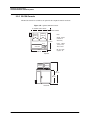
Dimension 3100 SPM Overview
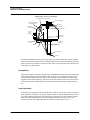
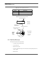
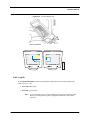
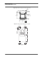
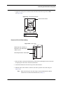
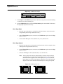
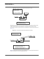
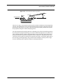
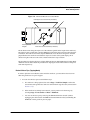
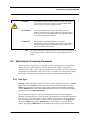
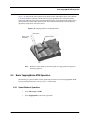
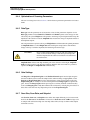
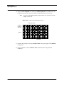
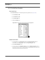
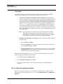
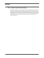
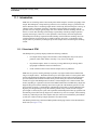
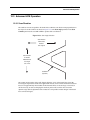
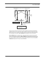
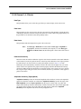
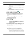
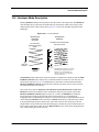
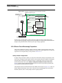
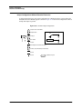
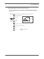
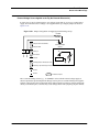
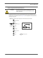
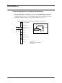
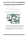
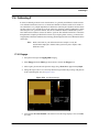
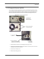
Figure 1.3b Dimension SPM Head
La ser Sp ot Detector Screen (d ark r ed )
L aser aim adju stmen ts
Po sition Se nsitive De tecto r
(special photo diode)
Laser dio de
Collimator
Beamsp litter
(behin d scr ee n)
Focusing lens
Detector
Mirror
po sitio ne rs
Laser L ight's
Beam path
Tracking Le ns
(corrective)
Adjustabl e(d etecto r)
mi rror
Fi xed mir ro r
Lens
Probe Tip Holder
Cantilever
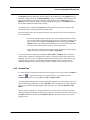
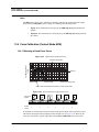
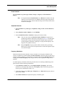
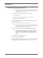
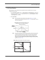
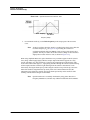
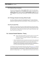
The Dimension SPM head scans the tip and generates the cantilever deflection or probe feedback
signal for the different imaging modes. A quad photodetector detects the beam emitted by the laser
diode (1.0 mW max at 670nm) as it reflects off the cantilever. The integrated scanner head consists
of the following subassemblies:
Preamp Board
The preamp board is located inside the Dimension 3100 SPM microscope head. The preamp board
contains a preamplifier circuit for both photodetector signals, a laser diode power supply circuit
that regulates the output of the laser, and ±12 volt regulators for the preamp circuit. The voltage
regulators include current limiting to protect the circuit. The preamp board is in turn connected to a
21-pin male connector cable plugged into the socket on the front of the stage control electronics
box.
Laser Diode Stage
A kinematic tilt stage positions the laser beam on the cantilever. The tilt stage consists of the laser
diode, collimator, focusing lens, base plate, and the X and Y laser diode adjustment knobs. The X
laser diode adjustment knob moves the beam parallel to the major axis of the cantilever substrate.
The Y laser diode adjustment knob moves the beam perpendicular to the major axis of the
cantilever substrate. The adjustment knobs are described in more detail in Chapter 7.
10
Dimension 3100 Manual
Rev. D