1
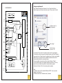
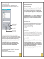
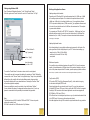
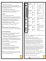
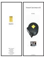
Professional PC Audio Interface for USB
User Manual
www.yellowtec.com
[email protected]
made in germany
YELLOWTEC is a brandname of
THUM+MAHR GMBH
Heinrich-Hertz-Strasse 1-3
D-40789 Monheim
Tel. ++49 (0) 2173/967-315
Fax ++49 (0) 2173/967-400
www.thummahr.de
12
1
www.yellowtec.com
Notice of Warranty
The terms and conditions of the Warranty applying to the Product accompanying this Notice
of Warranty are found exclusively in the Notice of Warranty. To the extent there is any
inconsistency of conflict between the terms and conditions of the Notice of Warranty and the
terms and conditions found anywhere else, including the Manual accompanying this Product,
the terms and conditions of this Notice of Warranty are superseding and control.
This Warranty covers "the Products", which are defined as the various audio equipment,
parts, software and accessories manufactured, sold and/or distributed by Thum + Mahr
GmbH (hereinafter "T+M").
With the exception of software-only items, the Products are warranted to be free from defects
in material and workmanship for a period of one year from the date of receipt by the enduser. Software-only items are warranted to be free from defects in material and workmanship
for a period of 90 days from the date of receipt by the end-user. The terms and conditions of
T+M's warranty in effect at the time of shipment shall apply. In order to invoke this Warranty,
notice of a warranty claim must be received by T+M within the above-stated warranty period
and warranty coverage must be authorized by T+M. Notice of a warranty claim may be made
orally by telephoning (++49-2173-967300) or in writing sent by facsimile (++49-2173967400) to or by e-mail ([email protected]). If T+M authorizes the performance of
warranty service and if T+M will be performing the warranty service, the
defective Product must be delivered, shipping prepaid, to: T+M, Heinrich-Hertz-Str. 1-3, D40789 Monheim, Germany. If T+M authorizes the performance of warranty service and if it
authorizes another entity to perform that warranty service, the Product must be delivered,
shipping prepaid, to that entity, whose address will be provided by T+M. T+M (or its
designee) at its option will either repair or replace the Product and such action shall be the
full extent of T+M's obligation, and buyer's sole remedy, under this Warranty. After the
Product is repaired or replaced, T+M (or its designee) will return it to the party that sent the
Product and T+M will pay for the cost of shipping. T+M will have no responsibility under this
Warranty for any Products subject to: Acts of God, including (without limitation) lightning;
improper installation or misuse, including (without limitation) the failure to use telephone and
power line surge protection devices; accident; neglect or damage. T+M's dealers are not
authorized to assume for T+M any additional obligations or liabilities in connection with the
dealers' sale of the Products.
Scope of delivery
- PUC unit
- USB cable, "A/B" type
- User Manual
- 4 self-adhesive bumper feet *
- additional datasheets in case of special versions
Before using this unit, please make sure
to read the safety instructions on page 10
EXCEPT FOR THE ABOVE-STATED WARRANTY, T+M MAKES NO WARRANTIES, EXPRESS OR
IMPLIED (INCLUDING IMPLIED WARRANTIES OF MERCHANTABILITY AND FITNESS FOR A
PARTICULAR PURPOSE).
In no event will T+M, its employees, agents or authorized dealers be liable for incidental or
consequential damages, or for loss, damage, or expense directly or indirectly arising from the
use of any Product or the inability to use any Product either separately or in combination with
other equipment or materials, or from any other cause.
Limited Warranty Duration
* Give your PUC a more firm stand by mounting the self-adhesive bumper feet. Take them off the
protection sheet and place them evenly spread on the bottom side, close to the outer edge.
2
The duration of limited warranty for YELLOWTEC PUC is one year according to the terms and
conditions of warranty of the manufacterer (siehe Notice Of Warranty).
11
Safety instructions
Connection
-
Before installation or operation of equipment read all safety instructions warnings and
operating instructions.
-
Heed all warnings on the equipment.
-
Follow the operating instructions.
Yellowtec PUC is designed to operate as an Audio Converter at a USB port of your PC.
PUC draws its power supply from the PC USB port.
External supply is not needed, therefore a power input connector is not provided.
-
Only use the equipment for the purpose and in the way as described in the operating
manual.
Connecting cable
-
Keep operating instructions for future reference.
-
Never use the equipment in the immediate vicinity of water. Ensure that water or damp
cannot get into the equipment.
-
Only install or fit the equipment in accordance with the manufacturers recommendations.
-
Ensure adequate ventilation when installing.
-
Never use the equipment in places that have temperatures above +40°C or below -10°C .
-
Ensure that foreign objects and liquids cannot get into the equipment.
-
Only clean the equipment as recommended by the manufacturer.
-
In any situation where an incident occurs which could render the equipment unsafe, for
example
Please use the enclosed USB cable.
If you want to use another cable, make sure it meets USB specifications.
("A/B" type cable, compatible with USB 1.1 oder higher, max. lenght 5mtr)
PC connection, direct
Connect the USB socket on the PUC front panel with a standard USB port of your PC
using the USB cable provided.
(PC USB port compatible with USB 1.1 oder higher and "A" type socket.)
PC connection, via USB hub
Connect the USB socket on the PUC front panel with a USB port of your USB hub
using the USB cable provided.
(Hub compatible with USB 1.1 oder higher and "A" type socket.)
- entry of foreign objects or liquids (including water) into the equipment
- the equipment has been dropped or the casing has been damaged in any way
- damage to a connection cable
In most cases you will need a hub with its own power supply ("self-powered").
- any apparent change in performance
Note: A standard USB port can deliver current up to 500mA. Hubs without power
supply consume a small amount of that current for active signal processing and
distribute the rest among the outgoing USB ports. This may result in a lack of power
when running a PUC on such a port.
In this case use a self-powered hub that can deliver up to 400mA on each
outgoing port.
have the equipment checked immediately by a person technically qualified to make
such checks.
-
Never carry out any work on the equipment other than as specified in the operating
manual.
Audio ports
PUC provides analogue and digital audio ports.
The analogue ports are in the professional studio format and deliver superb audio
quality. The electronically balanced input and output circuitry can supply levels up
to +18dBu without loss when operated unbalanced. International and german level
standards are available.
In the digital domain high quality S/PDIF input and output ports with SRA
(Sample Rate Auto Sensing) are provided.
As a special version PUC is available with transformer balanced AES/EBU ports*.
* particular specifications apply, see "technical data"
10
3
PUC automatically selects the audio source.
SUB-D25F
If a digital audio signal is present at the digital input, this input will be selected.
(Only condition: the input signal must be in a format that PUC identifies as convertable.)
Otherwise the analogue inputs are selected.
25
13
Sub-D
GPI
Standard: S/PDIF
Signal
Shield
Pin 14
Pin 2
Optional:
Signal+
SignalShield
Pin 14
Pin 2
Pin 15
ZLM
BYPASS
INT LVL
Digital Audio Input
AES/EBU
The outputs, digital and analogue, are simultaneously active.
The headphones output with its own driver circuitry enables you to monitor audio
signals processed by PUC without the need of additional equipment.
Digital Audio Output
Standard: S/PDIF
Signal
Shield
Pin 3
Pin 16
Audio Options
Optional:
Signal+
SignalShield
Pin 3
Pin 16
Pin 15
AES/EBU
Via GPI (control input ports) you can select 3 functions:
1. ZLM (Zero Latency Monitoring). When active, the analogue input signal is added
(via summing amp) to the analogue output signal. This function allows you to monitor
the input signal without latency time caused by audio processing in a PC.
14
1
3. INT LVL (International Level). When active, PUC is set up for international
analogue Level standards: i.e. ref. Lvl. +4dBu / max. Lvl. +18dBu.
… new hardware found … USB Audio Codec ... USB audio device … is being installed …
... the new hardware has been successfully installed and can be used …
All drivers required belong to the standard Windows operating system. If, out of any
reason, a driver is missing on your PC, you are prompted to insert your Windows CD,
so the driver can be reinstalled.
Previously active soundcard setups will be automatically deactivated.
PUC is a real Plug 'n Play device.
You do not need any special driver to run PUC on your PC.
The only setting, that we recommend, concerns the audio playback volume of
Windows (described in the following). This setting will assure, that PUC output
levels in playback mode meet professional studio standards.
Note:
Driver installation and settings are stored by Windows separately for each USB port. When you run PUC on
another USB port of your PC later, the installation routine described above will come up again. In this case we
recommend to redo the setting described in the following as well.
Aux Power Out
Sub-D
digital +5V/max. 40mA
digital 0V
analog +15V/max. 10mA
analog +15V/max. 10mA
analog 0V
Pin
Pin
Pin
Pin
Pin
No short-circuit protection provided on AUX POWER OUT!
Ground Input/Frontpanel Sub-D Pin 1
Signal+
SignalShield
Pin 25
Pin 13
Pin 12
Headphones 3,5mm Jack Connector
Signal+
SignalShield
Pin 24
Pin 11
Pin 12
Left Channel
Tip
Right Channel
Ring
analog 0V
Case
LED Displays
Analog Audio Output
Sub-D
Type RG lights red - USB initialisation process
Left Channel
Signal+
SignalShield
Pin 9
Pin 21
Pin 22
Type RG lights green - normal operation
Signal+
SignalShield
Pin 10
Pin 23
Pin 22
RG
Right Channel
USB
LED Displays
Type R lights red - analog ZLM and/or
digital Bypass active
USB Connector
"B"-Type, USB 1.1, Power Supply via USB
TECHNICAL DATA
- Full USB 1.1 Compliance; compatible to MS Windows 98 (2nd ed.)/2000/ME/XP, Mac OS 9 or higher
- Power Supply via USB, less than 400mA typ.
- USB Asynchronous Mode for Record / USB Adaptive Mode for Playback
- Copy Management for S/PDIF Input and Output; SCMS (Serial Copy Management System)
- Stereo Analogue Inputs electronically balanced with Ref. Level +6dBu / max. Level +15dBu
via GPI switchable to Ref. Level +4dBu / max. Level +18dBu / Input impedance 20KOhm
- Stereo Analogue Outputs electronically balanced with Ref. Lvl. +6dBu / max. Level +15dBu
via GPI switchable to Ref. Lvl. +4dBu / max. Level +18dBu / Load > 600 Ohm
- Stereo Headphones Output max. Level +20dBu (unloaded) Impedance 300 Ohm, Load > 600 Ohm
- Stereo Digital Audio Input and Output in the S/PDIF format (special version with AES/EBU ports
available, particular specifications apply, please refer to datasheet provided with special version)
- 16 Bit Delta Sigma A/D and D/A conversion, supported sample rates A/D 8kHz, 11.025 kHz,
16kHz, 22.05kHz, 32kHz, 44.1kHz, 48kHz, D/A 32kHz, 44.1kHz, 48kHz
- Noise 88dBr typ. (A/D), 95dBr typ. (D/A), (QPeak, 22Hz-22kHz, A-weighted)
- GPI (control input ports) max. voltage range: dig. 0V ... +5V / active: 0V / non active: open or +5V
- AUX POWER OUT max. current 10mA, no short-circuit protection provided!
- Dimensions 140mm x 132mm x 27mm, weight approx. 200g
4
6
19
20
7
8
Right Channel
Note:
Maximum Level in the analogue domain refers to 0dBFS in the digital domain.
In normal operation mode 0dBFS refers to +15dBu, thus -9dBFS refers to +6dBu (german standard).
With "INT LVL" active, 0dBFS refers to +18dBu, thus +4dBu refers to -14dBFS (common international standard).
When you connect PUC to your PC it will be automatically identified and installed.
During this procedure Windows will show dialogues like:
active when connected to dig 0V, non active when left open
or connected to +5V. Do not exceed 0V ... +5V!
Headphones
R
Installation for MS Windows Users
Pin 18
Pin 17
Pin 5
Sub-D
Analog Audio Input
Left Channel
2. BYP (Digital Bypass). Hereby you switch a digital input signal directly to the
digital output. Audio data coming from the PC are cut out.
Sub-D
Sub-D
Zero Latency Mon.
Dig. Bypass
International Level
9
PUC complies with the requirements of EN 89/336/EEC
Settings using Windows XP
BLOCKDIAGRAMM
Open "Sounds and Audio Devices Properties" (in the "Control Panels" folder).
Select the register card "Volume" and set the control of "Device volume" to "High".
AES/EBU
AES/EBU
DEC
ALTERNATIVE OPTION
DIGITAL
INPUT
S/PDIF DEC
AUTO SIGNAL SELECT
set "Device volume" to
"High" (maximum)
L
ANALOG
INPUT
ADC
R
USB
DEV.
INT LVL
GPI
USB
TO PC
Sample
Rate
Manager
ZLM
GPI
L
ANALOG
OUTPUT
R
DAC
click on "Apply"
close the window
by a click on "OK"
L
PHONES
OUTPUT
R
The controller "Device volume" is the master volume control for sound playback.
This controller can also be accessed by selecting the register card "Audio" followed by
a mouse-click on the "Volume" button in the playback range. Though it may be labelled
different there, the controller that can be identified as master volume control is
functionally identical with the one described above.
BYPASS
GPI
DIGITAL
OUTPUT
POWER
MANAGER
S/PDIF ENC
digital
REG
One more possibility to access the controller is from the Windows "Taskbar".
You can activate this option in the adequate checkbox shown above. If you do so,
please be concerned about the possibility of unintended faulty operation.
ALTERNATIVE OPTION
AES/EBU
AES/EBU
ENC
DC
analog
DC
Selecting the Checkbox "Mute" will cut sound playback completely.
Note:
The Windows driver for PUC is labelled "USB Audio CODEC". It does not provide
settings for recording level.
PUC itself is referred to as "USB audio device" by Windows.
AUX POWER
OUTPUT
8
5
Settings using Windows 2000
Working with application software
Open "Sounds and Multimedia Properties" (in the "Control Panels" folder).
Select the register card "Sounds" and set the control of "Sound Volume" to "High".
Adapting analogue level standards
Depending on its GPI settings PUC can handle maximum levels of +15dBu resp. +18dBu
at the analogue inputs and outputs. This is related to the specified reference levels of
+6dBu resp. +4dBu only by the settings (default or user) of your application software.
If PUC is operated in delivery status (+15dBu max. level), your application software needs
to be set in the way that reference level is 9dB lower than maximum level. This complies
to german studio standards.
If you operate your PUC with the GPI "INT LVL" activated (i.e. +18dBu max. level), your
application software needs to be set in the way that reference level is 14dB lower than
maximum level (i.e. +4dBu). This complies to common international studio standards.
see also page 4: Audio Options
Adapting digital audio formats
Audio format settings of your application software must correspond to the format of the
audio signal that is fed into the digital input of your PUC. These are basic settings, e.g.
set "Sound Volume" to
"High" (maximum)
- sample rate (e.g. 32kHz, 44.1kHz, 48kHz)
- resolution (be concerned: PUC max. 16bit)
- mono/stereo
click on "Apply"
Multichannel operation
close the window
by a click on "OK"
It is possible to set up multichannel systems with several PUCs. In theory the maximum
number of channels depends on USB data thruput. But in practice it depends on the interaction of all system components like PC hardware, operation system, application software.
The controller "Sound Volume" is the master volume control for sound playback.
Note: In theory it is possible to transfer more than 16 stereo audio signals simultaneously via USB 1.1
This controller can also be accessed by selecting the register card "Audio" followed by
a mouse-click on the "Volume" button in the playback range. Though it may be labelled
different there, the controller that can be identified as master volume control is
functionally identical with the one described above. Selecting the Checkbox "Mute"
will cut sound playback completely.
Copy Protection (SCMS)
PUC provides Serial Copy Management System (SCMS), a system which restricts copying
audio data in the digital format.
One more possibility to access the controller is from the Windows "Taskbar".
You can activate this option in the adequate checkbox shown above. If you do so,
please be concerned about the possibility of unintended faulty operation.
When copying "original" audio data (e.g. from CD to MD), a so called "copy flag" is set
in the audio header data. This has no audible effect on the MD copy, but when this copy
is fed to the digital input of any device that is equipped with SCMS, these audio data will
be denied. PUC will in this case select the analogue inputs.
Audio data created in your application software and then fed through the PUC digital
output are in the original format, i.e. the copy flag is not set.
Note:
The Windows driver for PUC is labelled "USB Audio CODEC". It does not provide
settings for recording level.
PUC itself is referred to as "USB audio device" by Windows.
6
7
Settings using Windows 2000
Working with application software
Open "Sounds and Multimedia Properties" (in the "Control Panels" folder).
Select the register card "Sounds" and set the control of "Sound Volume" to "High".
Adapting analogue level standards
Depending on its GPI settings PUC can handle maximum levels of +15dBu resp. +18dBu
at the analogue inputs and outputs. This is related to the specified reference levels of
+6dBu resp. +4dBu only by the settings (default or user) of your application software.
If PUC is operated in delivery status (+15dBu max. level), your application software needs
to be set in the way that reference level is 9dB lower than maximum level. This complies
to german studio standards.
If you operate your PUC with the GPI "INT LVL" activated (i.e. +18dBu max. level), your
application software needs to be set in the way that reference level is 14dB lower than
maximum level (i.e. +4dBu). This complies to common international studio standards.
see also page 4: Audio Options
Adapting digital audio formats
Audio format settings of your application software must correspond to the format of the
audio signal that is fed into the digital input of your PUC. These are basic settings, e.g.
set "Sound Volume" to
"High" (maximum)
- sample rate (e.g. 32kHz, 44.1kHz, 48kHz)
- resolution (be concerned: PUC max. 16bit)
- mono/stereo
click on "Apply"
Multichannel operation
close the window
by a click on "OK"
It is possible to set up multichannel systems with several PUCs. In theory the maximum
number of channels depends on USB data thruput. But in practice it depends on the interaction of all system components like PC hardware, operation system, application software.
The controller "Sound Volume" is the master volume control for sound playback.
Note: In theory it is possible to transfer more than 16 stereo audio signals simultaneously via USB 1.1
This controller can also be accessed by selecting the register card "Audio" followed by
a mouse-click on the "Volume" button in the playback range. Though it may be labelled
different there, the controller that can be identified as master volume control is
functionally identical with the one described above. Selecting the Checkbox "Mute"
will cut sound playback completely.
Copy Protection (SCMS)
PUC provides SCMS ("Serial Copy Management System"), which restricts the copying
of audio data in the digital S/PDIF format.
One more possibility to access the controller is from the Windows "Taskbar".
You can activate this option in the adequate checkbox shown above. If you do so,
please be concerned about the possibility of unintended faulty operation.
Original audio data with copy protection (active "copy bit") can only be copied once in
the digital S/PDIF format. If this copy is fed to a device with SCMS, it will not be accepted.
According to RIAA conventions all consumer digital audio recorders are equipped with
SCMS (MiniDisc, CD-R Audio, DAT, etc.).
PUC will switch over to the analogue inputs when a copy of protected audio material is fed
to its S/PDIF input. In this case use the analogue audio format.
Note:
The Windows driver for PUC is labelled "USB Audio CODEC". It does not provide
settings for recording level.
PUC itself is referred to as "USB audio device" by Windows.
6
Audio data played back through PUC is marked as original audio data with copy protection.
7
Settings using Windows XP
BLOCKDIAGRAMM
Open "Sounds and Audio Devices Properties" (in the "Control Panels" folder).
Select the register card "Volume" and set the control of "Device volume" to "High".
AES/EBU
AES/EBU
DEC
ALTERNATIVE OPTION
DIGITAL
INPUT
S/PDIF DEC
AUTO SIGNAL SELECT
set "Device volume" to
"High" (maximum)
L
ANALOG
INPUT
ADC
R
USB
DEV.
INT LVL
GPI
USB
TO PC
Sample
Rate
Manager
ZLM
GPI
L
ANALOG
OUTPUT
R
DAC
click on "Apply"
close the window
by a click on "OK"
L
PHONES
OUTPUT
R
The controller "Device volume" is the master volume control for sound playback.
This controller can also be accessed by selecting the register card "Audio" followed by
a mouse-click on the "Volume" button in the playback range. Though it may be labelled
different there, the controller that can be identified as master volume control is
functionally identical with the one described above.
BYPASS
GPI
DIGITAL
OUTPUT
POWER
MANAGER
S/PDIF ENC
digital
REG
One more possibility to access the controller is from the Windows "Taskbar".
You can activate this option in the adequate checkbox shown above. If you do so,
please be concerned about the possibility of unintended faulty operation.
ALTERNATIVE OPTION
AES/EBU
AES/EBU
ENC
DC
analog
DC
Selecting the Checkbox "Mute" will cut sound playback completely.
Note:
The Windows driver for PUC is labelled "USB Audio CODEC". It does not provide
settings for recording level.
PUC itself is referred to as "USB audio device" by Windows.
AUX POWER
OUTPUT
8
5
PUC automatically selects the audio source.
SUB-D25F
If a digital audio signal is present at the digital input, this input will be selected.
(Only condition: the input signal must be in a format that PUC identifies as convertable.)
Otherwise the analogue inputs are selected.
25
13
Sub-D
GPI
Standard: S/PDIF
Signal
Shield
Pin 14
Pin 2
Optional:
Signal+
SignalShield
Pin 14
Pin 2
Pin 15
ZLM
BYPASS
INT LVL
Digital Audio Input
AES/EBU
The outputs, digital and analogue, are simultaneously active.
The headphones output with its own driver circuitry enables you to monitor audio
signals processed by PUC without the need of additional equipment.
Digital Audio Output
Standard: S/PDIF
Signal
Shield
Pin 3
Pin 16
Audio Options
Optional:
Signal+
SignalShield
Pin 3
Pin 16
Pin 15
AES/EBU
Via GPI (control input ports) you can select 3 functions:
1. ZLM (Zero Latency Monitoring). When active, the analogue input signal is added
(via summing amp) to the analogue output signal. This function allows you to monitor
the input signal without latency time caused by audio processing in a PC.
14
1
3. INT LVL (International Level). When active, PUC is set up for international
analogue Level standards: i.e. ref. Lvl. +4dBu / max. Lvl. +18dBu.
… new hardware found … USB Audio Codec ... USB audio device … is being installed …
... the new hardware has been successfully installed and can be used …
All drivers required belong to the standard Windows operating system. If, out of any
reason, a driver is missing on your PC, you are prompted to insert your Windows CD,
so the driver can be reinstalled.
Previously active soundcard setups will be automatically deactivated.
PUC is a real Plug 'n Play device.
You do not need any special driver to run PUC on your PC.
The only setting, that we recommend, concerns the audio playback volume of
Windows (described in the following). This setting will assure, that PUC output
levels in playback mode meet professional studio standards.
Note:
Driver installation and settings are stored by Windows separately for each USB port. When you run PUC on
another USB port of your PC later, the installation routine described above will come up again. In this case we
recommend to redo the setting described in the following as well.
Aux Power Out
Sub-D
digital +5V/max. 40mA
digital 0V
analog +15V/max. 10mA
analog -15V/max. 10mA
analog 0V
Pin
Pin
Pin
Pin
Pin
No short-circuit protection provided on AUX POWER OUT!
Ground Input/Frontpanel Sub-D Pin 1
Signal+
SignalShield
Pin 25
Pin 13
Pin 12
Headphones 3,5mm Jack Connector
Signal+
SignalShield
Pin 24
Pin 11
Pin 12
Left Channel
Tip
Right Channel
Ring
analog 0V
Case
LED Displays
Analog Audio Output
Sub-D
Type RG lights red - USB initialisation process
Left Channel
Signal+
SignalShield
Pin 9
Pin 21
Pin 22
Type RG lights green - normal operation
Signal+
SignalShield
Pin 10
Pin 23
Pin 22
RG
Right Channel
USB
LED Displays
Type R lights red - analog ZLM and/or
digital Bypass active
USB Connector
"B"-Type, USB 1.1, Power Supply via USB
TECHNICAL DATA
- Full USB 1.1 Compliance; compatible to MS Windows 98 (2nd ed.)/2000/ME/XP, Mac OS 9 or higher
- Power Supply via USB, less than 400mA typ.
- USB Asynchronous Mode for Record / USB Adaptive Mode for Playback
- Copy Management for S/PDIF Input and Output; SCMS (Serial Copy Management System)
- Stereo Analogue Inputs electronically balanced with Ref. Level +6dBu / max. Level +15dBu
via GPI switchable to Ref. Level +4dBu / max. Level +18dBu / Input impedance 20KOhm
- Stereo Analogue Outputs electronically balanced with Ref. Lvl. +6dBu / max. Level +15dBu
via GPI switchable to Ref. Lvl. +4dBu / max. Level +18dBu / Load > 600 Ohm
- Stereo Headphones Output max. Level +20dBu (unloaded) Impedance 300 Ohm, Load > 600 Ohm
- Stereo Digital Audio Input and Output in the S/PDIF format (special version with AES/EBU ports
available, particular specifications apply, please refer to datasheet provided with special version)
- 16 Bit Delta Sigma A/D and D/A conversion, supported sample rates A/D 8kHz, 11.025 kHz,
16kHz, 22.05kHz, 32kHz, 44.1kHz, 48kHz, D/A 32kHz, 44.1kHz, 48kHz
- Noise A/D 88dBr, D/A 88dBr (95dBr with AutoMute), 22Hz-22kHz, QPeak, A-weighted, typ.
- GPI (control input ports) max. voltage range: dig. 0V ... +5V / active: 0V / non active: open or +5V
- AUX POWER OUT max. current 10mA, no short-circuit protection provided!
- Dimensions 140mm x 132mm x 27mm, weight approx. 200g
4
6
19
20
7
8
Right Channel
Note:
Maximum Level in the analogue domain refers to 0dBFS in the digital domain.
In normal operation mode 0dBFS refers to +15dBu, thus -9dBFS refers to +6dBu (german standard).
With "INT LVL" active, 0dBFS refers to +18dBu, thus +4dBu refers to -14dBFS (common international standard).
When you connect PUC to your PC it will be automatically identified and installed.
During this procedure Windows will show dialogues like:
active when connected to dig 0V, non active when left open
or connected to +5V. Do not exceed 0V ... +5V!
Headphones
R
Installation for MS Windows Users
Pin 18
Pin 17
Pin 5
Sub-D
Analog Audio Input
Left Channel
2. BYP (Digital Bypass). Hereby you switch a digital input signal directly to the
digital output. Audio data coming from the PC are cut out.
Sub-D
Sub-D
Zero Latency Mon.
Dig. Bypass
International Level
9
PUC complies with the requirements of EN 89/336/EEC
Safety instructions
Connection
-
Before installation or operation of equipment read all safety instructions warnings and
operating instructions.
-
Heed all warnings on the equipment.
-
Follow the operating instructions.
Yellowtec PUC is designed to operate as an Audio Converter at a USB port of your PC.
PUC draws its power supply from the PC USB port.
External supply is not needed, therefore a power input connector is not provided.
-
Only use the equipment for the purpose and in the way as described in the operating
manual.
Connecting cable
-
Keep operating instructions for future reference.
-
Never use the equipment in the immediate vicinity of water. Ensure that water or damp
cannot get into the equipment.
-
Only install or fit the equipment in accordance with the manufacturers recommendations.
-
Ensure adequate ventilation when installing.
-
Never use the equipment in places that have temperatures above +40°C or below -10°C .
-
Ensure that foreign objects and liquids cannot get into the equipment.
-
Only clean the equipment as recommended by the manufacturer.
-
In any situation where an incident occurs which could render the equipment unsafe, for
example
Please use the enclosed USB cable.
If you want to use another cable, make sure it meets USB specifications.
("A/B" type cable, compatible with USB 1.1 oder higher, max. lenght 5mtr)
PC connection, direct
Connect the USB socket on the PUC front panel with a standard USB port of your PC
using the USB cable provided.
(PC USB port compatible with USB 1.1 oder higher and "A" type socket.)
PC connection, via USB hub
Connect the USB socket on the PUC front panel with a USB port of your USB hub
using the USB cable provided.
(Hub compatible with USB 1.1 oder higher and "A" type socket.)
- entry of foreign objects or liquids (including water) into the equipment
- the equipment has been dropped or the casing has been damaged in any way
- damage to a connection cable
In most cases you will need a hub with its own power supply ("self-powered").
- any apparent change in performance
Note: A standard USB port can deliver current up to 500mA. Hubs without power
supply consume a small amount of that current for active signal processing and
distribute the rest among the outgoing USB ports. This may result in a lack of power
when running a PUC on such a port.
In this case use a self-powered hub that can deliver up to 400mA on each
outgoing port.
have the equipment checked immediately by a person technically qualified to make
such checks.
-
Never carry out any work on the equipment other than as specified in the operating
manual.
Audio ports
PUC provides analogue and digital audio ports.
The analogue ports are in the professional studio format and deliver superb audio
quality. The electronically balanced input and output circuitry can supply levels up
to +18dBu without loss when operated unbalanced. International and german level
standards are available.
In the digital domain high quality S/PDIF input and output ports with SRA
(Sample Rate Auto Sensing) are provided.
As a special version PUC is available with transformer balanced AES/EBU ports*.
* particular specifications apply, see "technical data"
10
3
Notice of Warranty
The terms and conditions of the Warranty applying to the Product accompanying this Notice
of Warranty are found exclusively in the Notice of Warranty. To the extent there is any
inconsistency of conflict between the terms and conditions of the Notice of Warranty and the
terms and conditions found anywhere else, including the Manual accompanying this Product,
the terms and conditions of this Notice of Warranty are superseding and control.
This Warranty covers "the Products", which are defined as the various audio equipment,
parts, software and accessories manufactured, sold and/or distributed by Thum + Mahr
GmbH (hereinafter "T+M").
With the exception of software-only items, the Products are warranted to be free from defects
in material and workmanship for a period of one year from the date of receipt by the enduser. Software-only items are warranted to be free from defects in material and workmanship
for a period of 90 days from the date of receipt by the end-user. The terms and conditions of
T+M's warranty in effect at the time of shipment shall apply. In order to invoke this Warranty,
notice of a warranty claim must be received by T+M within the above-stated warranty period
and warranty coverage must be authorized by T+M. Notice of a warranty claim may be made
orally by telephoning (++49-2173-967300) or in writing sent by facsimile (++49-2173967400) to or by e-mail ([email protected]). If T+M authorizes the performance of
warranty service and if T+M will be performing the warranty service, the
defective Product must be delivered, shipping prepaid, to: T+M, Heinrich-Hertz-Str. 1-3, D40789 Monheim, Germany. If T+M authorizes the performance of warranty service and if it
authorizes another entity to perform that warranty service, the Product must be delivered,
shipping prepaid, to that entity, whose address will be provided by T+M. T+M (or its
designee) at its option will either repair or replace the Product and such action shall be the
full extent of T+M's obligation, and buyer's sole remedy, under this Warranty. After the
Product is repaired or replaced, T+M (or its designee) will return it to the party that sent the
Product and T+M will pay for the cost of shipping. T+M will have no responsibility under this
Warranty for any Products subject to: Acts of God, including (without limitation) lightning;
improper installation or misuse, including (without limitation) the failure to use telephone and
power line surge protection devices; accident; neglect or damage. T+M's dealers are not
authorized to assume for T+M any additional obligations or liabilities in connection with the
dealers' sale of the Products.
Scope of delivery
- PUC unit
- USB cable, "A/B" type
- User Manual
- 4 self-adhesive bumper feet *
- additional datasheets in case of special versions
Before using this unit, please make sure
to read the safety instructions on page 10
EXCEPT FOR THE ABOVE-STATED WARRANTY, T+M MAKES NO WARRANTIES, EXPRESS OR
IMPLIED (INCLUDING IMPLIED WARRANTIES OF MERCHANTABILITY AND FITNESS FOR A
PARTICULAR PURPOSE).
In no event will T+M, its employees, agents or authorized dealers be liable for incidental or
consequential damages, or for loss, damage, or expense directly or indirectly arising from the
use of any Product or the inability to use any Product either separately or in combination with
other equipment or materials, or from any other cause.
Limited Warranty Duration
* Give your PUC a more firm stand by mounting the self-adhesive bumper feet. Take them off the
protection sheet and place them evenly spread on the bottom side, close to the outer edge.
2
The duration of limited warranty for YELLOWTEC PUC is one year according to the terms and
conditions of warranty of the manufacterer (siehe Notice Of Warranty).
11
Professional PC Audio Interface for USB
User Manual
www.yellowtec.com
[email protected]
made in germany
YELLOWTEC is a brandname of
THUM+MAHR GMBH
Heinrich-Hertz-Strasse 1-3
D-40789 Monheim
Tel. ++49 (0) 2173/967-315
Fax ++49 (0) 2173/967-400
www.thummahr.de
12
1
www.yellowtec.com