1
Title page
Nortel Communication Server 1000
Nortel Communication Server 1000 Release 4.5
Telephones and Consoles
Description, Installation, and Operation
Document Number: 553-3001-367
Document Release: Standard 3.00
Date: August 2005
Year Publish FCC TM
Copyright © Nortel Networks Limited 2005
All Rights Reserved
Produced in Canada
Information is subject to change without notice. Nortel Networks reserves the right to make changes in design
or components as progress in engineering and manufacturing may warrant.
Nortel, Nortel (Logo), the Globemark, This is the Way, This is Nortel (Design mark), SL-1, Meridian 1, and
Succession are trademarks of Nortel Networks.
4
Page 3 of 504
Revision history
August 2005
Standard 3.00. This document is up-issued for Communication Server 1000
Release 4.5.
September 2004
Standard 2.00. This document is up-issued for Communication Server 1000
Release 4.0.
October 2003
Standard 1.00. This document is a new NTP for Succession 3.0. It was created
to support a restructuring of the Documentation Library, which resulted in the
merging of multiple legacy NTPs. This new document consolidates
information previously contained in the following legacy documents, now
retired:
•
Attendant Console Description (553-2201-117)
•
Digital Telephones Line Engineering(553-2201-180)
•
Meridian 1 Telephones (553-3001-108)
•
Meridian 1 European Digital Telephones (553-3001-114)
•
Telephone and Attendant Console Installation (553-3001-215)
•
M3900 Series Meridian Digital Telephones (553-3001-216)
•
Option 11C and 11C Mini Technical Reference Guide (553-3011-100)
Content from Option 11C and 11C Mini Technical Reference Guide also
appears in Circuit Card: Description and Installation (553-3001-211).
Telephones and Consoles
Description, Installation, and Operation
Page 4 of 504
553-3001-367
Revision history
Standard 3.00
August 2005
10
Page 5 of 504
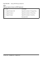
Contents
List of procedures . . . . . . . . . . . . . . . . . . . . . . . . . .
11
About this document . . . . . . . . . . . . . . . . . . . . . . .
19
Subject .. . . . . . . . . . . . . . . . . . . . . . . . . . . . . . . . . . . . . . . . . . . . . . . . .
19
Applicable systems . . . . . . . . . . . . . . . . . . . . . . . . . . . . . . . . . . . . . . . .
20
Intended audience . . . . . . . . . . . . . . . . . . . . . . . . . . . . . . . . . . . . . . . . .
21
Conventions .. . . . . . . . . . . . . . . . . . . . . . . . . . . . . . . . . . . . . . . . . . . . .
21
Related information .. . . . . . . . . . . . . . . . . . . . . . . . . . . . . . . . . . . . . . .
22
How to get Help . . . . . . . . . . . . . . . . . . . . . . . . . . . . . . . . . . . . . . . . . .
24
Attendant consoles . . . . . . . . . . . . . . . . . . . . . . . . .
27
Contents .. . . . . . . . . . . . . . . . . . . . . . . . . . . . . . . . . . . . . . . . . . . . . . . .
27
Introduction . . . . . . . . . . . . . . . . . . . . . . . . . . . . . . . . . . . . . . . . . . . . . .
28
Engineering codes . . . . . . . . . . . . . . . . . . . . . . . . . . . . . . . . . . . . . . . . .
29
Features . . . . . . . . . . . . . . . . . . . . . . . . . . . . . . . . . . . . . . . . . . . . . . . . .
31
Physical description .. . . . . . . . . . . . . . . . . . . . . . . . . . . . . . . . . . . . . . .
48
Wiring . . . . . . . . . . . . . . . . . . . . . . . . . . . . . . . . . . . . . . . . . . . . . . . . . .
57
Installation .. . . . . . . . . . . . . . . . . . . . . . . . . . . . . . . . . . . . . . . . . . . . . .
59
Operation .. . . . . . . . . . . . . . . . . . . . . . . . . . . . . . . . . . . . . . . . . . . . . . .
77
M2016S Secure Set . . . . . . . . . . . . . . . . . . . . . . . . . 103
Contents .. . . . . . . . . . . . . . . . . . . . . . . . . . . . . . . . . . . . . . . . . . . . . . . .
103
Introduction . . . . . . . . . . . . . . . . . . . . . . . . . . . . . . . . . . . . . . . . . . . . . .
104
Physical description .. . . . . . . . . . . . . . . . . . . . . . . . . . . . . . . . . . . . . . .
106
Telephones and Consoles
Description, Installation, and Operation
Page 6 of 504
Contents
Features . . . . . . . . . . . . . . . . . . . . . . . . . . . . . . . . . . . . . . . . . . . . . . . . .
108
Specifications . . . . . . . . . . . . . . . . . . . . . . . . . . . . . . . . . . . . . . . . . . . .
109
Installation . . . . . . . . . . . . . . . . . . . . . . . . . . . . . . . . . . . . . . . . . . . . . .
113
M 3900 description . . . . . . . . . . . . . . . . . . . . . . . . . 123
Contents . . . . . . . . . . . . . . . . . . . . . . . . . . . . . . . . . . . . . . . . . . . . . . . .
123
Introduction .. . . . . . . . . . . . . . . . . . . . . . . . . . . . . . . . . . . . . . . . . . . . .
124
Automatic Call Failover . . . . . . . . . . . . . . . . . . . . . . . . . . . . . . . . . . . .
126
Physical description . . . . . . . . . . . . . . . . . . . . . . . . . . . . . . . . . . . . . . .
127
Features . . . . . . . . . . . . . . . . . . . . . . . . . . . . . . . . . . . . . . . . . . . . . . . . .
137
M3900 accessories and add-ons . . . . . . . . . . . . . . . . . . . . . . . . . . . . . .
147
Key descriptions . . . . . . . . . . . . . . . . . . . . . . . . . . . . . . . . . . . . . . . . . .
159
M3900 (single site) Virtual Office . . . . . . . . . . . . . 173
Contents . . . . . . . . . . . . . . . . . . . . . . . . . . . . . . . . . . . . . . . . . . . . . . . .
173
Introduction .. . . . . . . . . . . . . . . . . . . . . . . . . . . . . . . . . . . . . . . . . . . . .
173
Description . . . . . . . . . . . . . . . . . . . . . . . . . . . . . . . . . . . . . . . . . . . . . .
173
Operating parameters . . . . . . . . . . . . . . . . . . . . . . . . . . . . . . . . . . . . . .
176
Feature implementation . . . . . . . . . . . . . . . . . . . . . . . . . . . . . . . . . . . .
177
M3900 installation and configuration . . . . . . . . . . 183
Contents . . . . . . . . . . . . . . . . . . . . . . . . . . . . . . . . . . . . . . . . . . . . . . . .
183
Reliability . . . . . . . . . . . . . . . . . . . . . . . . . . . . . . . . . . . . . . . . . . . . . . .
184
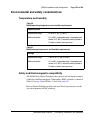
Environmental and safety considerations . . . . . . . . . . . . . . . . . . . . . . .
185
Installation . . . . . . . . . . . . . . . . . . . . . . . . . . . . . . . . . . . . . . . . . . . . . .
189
Configuration . . . . . . . . . . . . . . . . . . . . . . . . . . . . . . . . . . . . . . . . . . . .
206
M3900 Flash Download . . . . . . . . . . . . . . . . . . . . . 227
553-3001-367
Contents . . . . . . . . . . . . . . . . . . . . . . . . . . . . . . . . . . . . . . . . . . . . . . . .
227
Introduction .. . . . . . . . . . . . . . . . . . . . . . . . . . . . . . . . . . . . . . . . . . . . .
227
Summary of steps . . . . . . . . . . . . . . . . . . . . . . . . . . . . . . . . . . . . . . . . .
228
Determining software, M3900 PSWV, or firmware versions . . . . . . .
261
Standard 3.00
August 2005
Contents
Page 7 of 504
Flash Download advisements . . . . . . . . . . . . . . . . . . . . . . . . . . . . . . . .
263
PSDL installation . . . . . . . . . . . . . . . . . . . . . . . . . . . . . . . . . . . . . . . . .
267
Dynamic PSDL installation .. . . . . . . . . . . . . . . . . . . . . . . . . . . . . . . . .
267
Detailed Flash Download procedure . . . . . . . . . . . . . . . . . . . . . . . . . . .
269
Configuration parameters in LD 32 . . . . . . . . . . . . . . . . . . . . . . . . . . .
274
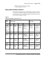
Print Firmware Versions on M3900 Telephones . . . . . . . . . . . . . . . . .
279
Query Disk Firmware Versions .. . . . . . . . . . . . . . . . . . . . . . . . . . . . . .
281
Commands for system-wide Flash Download of M3900 telephones .
284
Digital telephones line engineering . . . . . . . . . . . . 289
Contents .. . . . . . . . . . . . . . . . . . . . . . . . . . . . . . . . . . . . . . . . . . . . . . . .
289
Engineering a telephone line . . . . . . . . . . . . . . . . . . . . . . . . . . . . . . . . .
290
Selecting a Loop . . . . . . . . . . . . . . . . . . . . . . . . . . . . . . . . . . . . . . . . . .
299
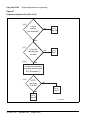
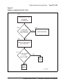
Calculating DC Loop Resistance . . . . . . . . . . . . . . . . . . . . . . . . . . . . .
299
Performing Loop Diagnostic Tests . . . . . . . . . . . . . . . . . . . . . . . . . . . .
300
Measuring Impulse Noise . . . . . . . . . . . . . . . . . . . . . . . . . . . . . . . . . . .
302
Measuring Background Noise .. . . . . . . . . . . . . . . . . . . . . . . . . . . . . . .
302
Calculating Expected Pulse Loss . . . . . . . . . . . . . . . . . . . . . . . . . . . . .
302
Measuring DC Loop Resistance . . . . . . . . . . . . . . . . . . . . . . . . . . . . . .
306
Analog (500/2500-type) telephones . . . . . . . . . . . . 309
Contents .. . . . . . . . . . . . . . . . . . . . . . . . . . . . . . . . . . . . . . . . . . . . . . . .
309
Introduction . . . . . . . . . . . . . . . . . . . . . . . . . . . . . . . . . . . . . . . . . . . . . .
309
Installation and removal . . . . . . . . . . . . . . . . . . . . . . . . . . . . . . . . . . . .
309
Operation .. . . . . . . . . . . . . . . . . . . . . . . . . . . . . . . . . . . . . . . . . . . . . . .
320
Appendix A: Meridian Modular Telephones . . . . . 323
Contents .. . . . . . . . . . . . . . . . . . . . . . . . . . . . . . . . . . . . . . . . . . . . . . . .
323
Introduction . . . . . . . . . . . . . . . . . . . . . . . . . . . . . . . . . . . . . . . . . . . . . .
324
General description . . . . . . . . . . . . . . . . . . . . . . . . . . . . . . . . . . . . . . . .
325
Physical description .. . . . . . . . . . . . . . . . . . . . . . . . . . . . . . . . . . . . . . .
330
Telephones and Consoles
Description, Installation, and Operation
Page 8 of 504
Contents
Features and options . . . . . . . . . . . . . . . . . . . . . . . . . . . . . . . . . . . . . . .
334
Relocation . . . . . . . . . . . . . . . . . . . . . . . . . . . . . . . . . . . . . . . . . . . . . . .
340
Specifications . . . . . . . . . . . . . . . . . . . . . . . . . . . . . . . . . . . . . . . . . . . .
342
Handsets . . . . . . . . . . . . . . . . . . . . . . . . . . . . . . . . . . . . . . . . . . . . . . . .
353
Appendix B: Meridian Modular Telephones
installation . . . . . . . . . . . . . . . . . . . . . . . . . . . . . . . . 355
Contents . . . . . . . . . . . . . . . . . . . . . . . . . . . . . . . . . . . . . . . . . . . . . . . .
355
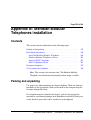
Packing and unpacking . . . . . . . . . . . . . . . . . . . . . . . . . . . . . . . . . . . . .
355
Installation and removal . . . . . . . . . . . . . . . . . . . . . . . . . . . . . . . . . . . .
356
Designate telephones . . . . . . . . . . . . . . . . . . . . . . . . . . . . . . . . . . . . . .
367
Cross-connect the telephones . . . . . . . . . . . . . . . . . . . . . . . . . . . . . . . .
368
Appendix C: Meridian Modular Telephones
add-on modules installation . . . . . . . . . . . . . . . . . 371
553-3001-367
Contents . . . . . . . . . . . . . . . . . . . . . . . . . . . . . . . . . . . . . . . . . . . . . . . .
371
Packing and unpacking . . . . . . . . . . . . . . . . . . . . . . . . . . . . . . . . . . . . .
372
Meridian Modular Telephones . . . . . . . . . . . . . . . . . . . . . . . . . . . . . . .
373
Analog Terminal Adapter . . . . . . . . . . . . . . . . . . . . . . . . . . . . . . . . . . .
375
Meridian Communications Adapter and Meridian
Programmable Data Adapter . . . . . . . . . . . . . . . . . . . . . . . . . . . . . . . .
381
Power Supply Board (NTZK models) . . . . . . . . . . . . . . . . . . . . . . . . .
392
Power Supply Board (NT2K models) .. . . . . . . . . . . . . . . . . . . . . . . . .
401
Installing displays . . . . . . . . . . . . . . . . . . . . . . . . . . . . . . . . . . . . . . . . .
404
External Alerter Board . . . . . . . . . . . . . . . . . . . . . . . . . . . . . . . . . . . . .
416
Key Expansion Modules . . . . . . . . . . . . . . . . . . . . . . . . . . . . . . . . . . . .
420
Asynchronous Data Option .. . . . . . . . . . . . . . . . . . . . . . . . . . . . . . . . .
423
M2317 Data Option . . . . . . . . . . . . . . . . . . . . . . . . . . . . . . . . . . . . . . .
426
Meridian Communications Unit . . . . . . . . . . . . . . . . . . . . . . . . . . . . . .
430
Wall mounting . . . . . . . . . . . . . . . . . . . . . . . . . . . . . . . . . . . . . . . . . . .
432
Troubleshooting . . . . . . . . . . . . . . . . . . . . . . . . . . . . . . . . . . . . . . . . . .
433
Standard 3.00
August 2005
Contents
Page 9 of 504
Appendix D: M2317 telephone . . . . . . . . . . . . . . . . 439
Contents .. . . . . . . . . . . . . . . . . . . . . . . . . . . . . . . . . . . . . . . . . . . . . . . .
439
Introduction . . . . . . . . . . . . . . . . . . . . . . . . . . . . . . . . . . . . . . . . . . . . . .
439
Feature description . . . . . . . . . . . . . . . . . . . . . . . . . . . . . . . . . . . . . . . .
441
Physical description .. . . . . . . . . . . . . . . . . . . . . . . . . . . . . . . . . . . . . . .
442
Specifications . . . . . . . . . . . . . . . . . . . . . . . . . . . . . . . . . . . . . . . . . . . .
453
Appendix E: M3110, M3310, and M3820 telephones
459
Contents .. . . . . . . . . . . . . . . . . . . . . . . . . . . . . . . . . . . . . . . . . . . . . . . .
459
Feature description . . . . . . . . . . . . . . . . . . . . . . . . . . . . . . . . . . . . . . . .
460
Physical description .. . . . . . . . . . . . . . . . . . . . . . . . . . . . . . . . . . . . . . .
466
Terminal options . . . . . . . . . . . . . . . . . . . . . . . . . . . . . . . . . . . . . . . . . .
472
Configuration and installation .. . . . . . . . . . . . . . . . . . . . . . . . . . . . . . .
474
Specifications . . . . . . . . . . . . . . . . . . . . . . . . . . . . . . . . . . . . . . . . . . . .
486
Index . . . . . . . . . . . . . . . . . . . . . . . . . . . . . . . . . . . . . 493
Telephones and Consoles
Description, Installation, and Operation
Page 10 of 504
553-3001-367
Contents
Standard 3.00
August 2005
18
Page 11 of 504
List of procedures
Procedure 1
Connecting the BLF/CGM to the
M2250 attendant console . . . . . . . . . . . . . . . . . . . . . . . . 35
Procedure 2
Checking the functionality of the
Busy Lamp Field/Console Graphics Module . . . . . . . . 42
Procedure 3
Removing the Busy Lamp
Field/Console Graphics Module . . . . . . . . . . . . . . . . . . . 43
Procedure 4
Installing an Attendant Supervisory Module
on an M2250 attendant console . . . . . . . . . . . . . . . . . . . 45
Procedure 5
Installing wiring . . . . . . . . . . . . . . . . . . . . . . . . . . . . . . . . 57
Procedure 6
Installing the M2250 attendant console . . . . . . . . . . . . 60
Procedure 7
Removing the M2250 attendant console . . . . . . . . . . . . 61
Procedure 8
Removing the M2250 attendant console top cover . . . 62
Procedure 9
Installing the M2250 attendant console top cover . . . . 63
Telephones and Consoles
Description, Installation, and Operation
Page 12 of 504
List of procedures
Procedure 10
Performing a loopback test on the
M2250 attendant console . . . . . . . . . . . . . . . . . . . . . . . . 64
Procedure 11
Designating keys on an M2250 attendant console . . . 65
Procedure 12
Cross-connecting attendant consoles . . . . . . . . . . . . . 69
Procedure 13
Entering the M2250 Diagnostics mode . . . . . . . . . . . . . 81
Procedure 14
Testing the Keyboard . . . . . . . . . . . . . . . . . . . . . . . . . . . 82
Procedure 15
Testing the LCD indicators . . . . . . . . . . . . . . . . . . . . . . 83
Procedure 16
Testing the data port . . . . . . . . . . . . . . . . . . . . . . . . . . . . 83
Procedure 17
Testing the ICS . . . . . . . . . . . . . . . . . . . . . . . . . . . . . . . . 83
Procedure 18
Testing the Busy Lamp Field/Console
Graphics Module . . . . . . . . . . . . . . . . . . . . . . . . . . . . . . . 84
Procedure 19
Checking the Alerter . . . . . . . . . . . . . . . . . . . . . . . . . . . . 84
Procedure 20
Testing the Display . . . . . . . . . . . . . . . . . . . . . . . . . . . . . 85
Procedure 21
Displaying the firmware version numbers . . . . . . . . . . 85
Procedure 22
Displaying and resetting the QMT2 switch status . . . . 85
553-3001-367
Standard 3.00
August 2005
List of procedures
Page 13 of 504
Procedure 23
Toggling control gates . . . . . . . . . . . . . . . . . . . . . . . . . . 86
Procedure 24
Installing the M2016S telephone . . . . . . . . . . . . . . . . . . 114
Procedure 25
M2016S self-test . . . . . . . . . . . . . . . . . . . . . . . . . . . . . . . 116
Procedure 26
Designating the M2016S telephone . . . . . . . . . . . . . . . . 119
Procedure 27
Cross-connecting the telephones . . . . . . . . . . . . . . . . . 119
Procedure 28
Installing the M3900 Series Digital Telephone . . . . . . . 189
Procedure 29
Changing the telephone position . . . . . . . . . . . . . . . . . 190
Procedure 30
Changing the telephone angle . . . . . . . . . . . . . . . . . . . . 190
Procedure 31
Wall-mounting the telephone . . . . . . . . . . . . . . . . . . . . . 191
Procedure 32
Installing the ACM . . . . . . . . . . . . . . . . . . . . . . . . . . . . . . 192
Procedure 33
Installing the wall transformer . . . . . . . . . . . . . . . . . . . . 194
Procedure 34
Installing the ATA . . . . . . . . . . . . . . . . . . . . . . . . . . . . . . 195
Procedure 35
Installing the Personal Directory PC Utility
software . . . . . . . . . . . . . . . . . . . . . . . . . . . . . . . . . . . . . . 197
Telephones and Consoles
Description, Installation, and Operation
Page 14 of 504
List of procedures
Procedure 36
Installing the KBA . . . . . . . . . . . . . . . . . . . . . . . . . . . . . . 198
Procedure 37
Installing the Single KBA footstand . . . . . . . . . . . . . . . 201
Procedure 38
Installing the Expansion KBA footstand . . . . . . . . . . . . 201
Procedure 39
Installing the DBA . . . . . . . . . . . . . . . . . . . . . . . . . . . . . . 202
Procedure 40
Removing the HookSwitch cover . . . . . . . . . . . . . . . . . 203
Procedure 41
Installing the cradle . . . . . . . . . . . . . . . . . . . . . . . . . . . . 203
Procedure 42
Installing the key caps . . . . . . . . . . . . . . . . . . . . . . . . . . 205
Procedure 43
Installing the Full Duplex Handsfree cartridge . . . . . . . 206
Procedure 44
Displaying the M3900 Diagnostics . . . . . . . . . . . . . . . . 263
Procedure 45
Engineering a telephone line . . . . . . . . . . . . . . . . . . . . . 290
Procedure 46
Calculating DC loop resistance . . . . . . . . . . . . . . . . . . . 299
Procedure 47
Testing foreign voltage . . . . . . . . . . . . . . . . . . . . . . . . . . 300
Procedure 48
Testing insulation resistance . . . . . . . . . . . . . . . . . . . . . 301
Procedure 49
Testing DC continuity . . . . . . . . . . . . . . . . . . . . . . . . . . . 301
553-3001-367
Standard 3.00
August 2005
List of procedures
Page 15 of 504
Procedure 50
Testing capacitance unbalance . . . . . . . . . . . . . . . . . . . 301
Procedure 51
Measuring impulse noise . . . . . . . . . . . . . . . . . . . . . . . . 302
Procedure 52
Measuring background noise . . . . . . . . . . . . . . . . . . . . 302
Procedure 53
Calculating expected pulse loss . . . . . . . . . . . . . . . . . . 304
Procedure 54
Installing an analog (500/2500-type) telephone . . . . . . 310
Procedure 55
Removing an analog (500/2500-type) telephone . . . . . 310
Procedure 56
Designating 500-type telephones . . . . . . . . . . . . . . . . . 311
Procedure 57
Removing the finger wheel from
analog 500-type telephone . . . . . . . . . . . . . . . . . . . . . . . 311
Procedure 58
Designating analog 2500-type telephone . . . . . . . . . . . 312
Procedure 59
Connecting analog (500/2500-type) telephones . . . . . . 312
Procedure 60
Cross-connecting the telephones . . . . . . . . . . . . . . . . . 313
Procedure 61
Installing Meridian Modular Telephones
(M2006/M2008/M2008HF/M2616/M2216ACD) . . . . . . . . 356
Procedure 62
Meridian Modular Telephones self-test . . . . . . . . . . . . . 358
Telephones and Consoles
Description, Installation, and Operation
Page 16 of 504
List of procedures
Procedure 63
Installing the M2317 telephone . . . . . . . . . . . . . . . . . . . 361
Procedure 64
Performing the M2317 telephone self-test . . . . . . . . . . 364
Procedure 65
Designating Meridian Modular Telephones . . . . . . . . . 368
Procedure 66
Cross-connecting the telephones . . . . . . . . . . . . . . . . . 368
Procedure 67
Installing and removing the
Analog Terminal Adapter . . . . . . . . . . . . . . . . . . . . . . . 377
Procedure 68
Installing and removing the Meridian
Communications Adapter or the Meridian
Programmable Data Adapter . . . . . . . . . . . . . . . . . . . . . 389
Procedure 69
Connecting the data terminal . . . . . . . . . . . . . . . . . . . . . 392
Procedure 70
Installing and removing the M2006/M2008
Power Supply Board on NTZK sets . . . . . . . . . . . . . . . 393
Procedure 71
Installing and removing the M2616/M2216ACD
Power Supply Board on NTZK sets . . . . . . . . . . . . . . . . 397
Procedure 72
Installing and removing the M2006 or M2008
Power Supply Board on NT2K sets . . . . . . . . . . . . . . . 401
Procedure 73
Installing and removing the M2616/M2216ACD
Display on NTZK sets . . . . . . . . . . . . . . . . . . . . . . . . . . 405
553-3001-367
Standard 3.00
August 2005
List of procedures
Page 17 of 504
Procedure 74
Installing and removing the M2616 Display
on NT2K sets . . . . . . . . . . . . . . . . . . . . . . . . . . . . . . . . . 408
Procedure 75
Installing NT2K28AA displays on
NTZK or NT2K sets . . . . . . . . . . . . . . . . . . . . . . . . . . . . . 411
Procedure 76
Installing and removing the
External Alerter Board . . . . . . . . . . . . . . . . . . . . . . . . . . 416
Procedure 77
Installing and removing Key Expansion Module(s)
on the M2616 and M2216ACD telephones . . . . . . . . . . 420
Procedure 78
Installing the M2317 data option . . . . . . . . . . . . . . . . . . 427
Procedure 79
Installing the M2317 data terminal . . . . . . . . . . . . . . . . . 428
Procedure 80
Wall mounting instructions for Meridian Modular
Telephones . . . . . . . . . . . . . . . . . . . . . . . . . . . . . . . . . . . 432
Procedure 81
Installing Meridian European digital telephones . . . . . 480
Procedure 82
Installing the Power Board . . . . . . . . . . . . . . . . . . . . . . . 481
Procedure 83
Adding a Headset (M3310 and M3820 only) . . . . . . . . . 483
Procedure 84
Adjusting the telephone to the
desktop shallow-angle position . . . . . . . . . . . . . . . . . . . 484
Telephones and Consoles
Description, Installation, and Operation
Page 18 of 504
List of procedures
Procedure 85
Wall mounting the telephone . . . . . . . . . . . . . . . . . . . . . 485
553-3001-367
Standard 3.00
August 2005
26
Page 19 of 504
About this document
This document is a global document. Contact your system supplier or your
Nortel representative to verify that the hardware and software described are
supported in your area.
Subject
This document provides technical information about Meridian analog, digital
and modular telephones and attendant consoles. This information includes
descriptions, features and specifications; installation and configuration
procedures; operation; administration; software, wiring and power
requirements; environmental and safety considerations; installing and using
add-on modules, data options, and software. A section is also provided on
engineering and configuring digital telephone lines.
This document does not provide information about IP Phones. For
information on IP Phones, refer to IP Phones: Description, Installation, and
Operation (553-3001-368).
Note on legacy products and releases
This NTP contains information about systems, components, and features that
are compatible with Nortel Communication Server 1000 Release 4.5
software. For more information on legacy products and releases, click the
Technical Documentation link under Support on the Nortel home page:
www.nortel.com
Telephones and Consoles
Description, Installation, and Operation
Page 20 of 504
About this document
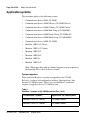
Applicable systems
This document applies to the following systems:
•
Communication Server 1000S (CS 1000S)
•
Communication Server 1000M Chassis (CS 1000M Chassis)
•
Communication Server 1000M Cabinet (CS 1000M Cabinet)
•
Communication Server 1000M Half Group (CS 1000M HG)
•
Communication Server 1000M Single Group (CS 1000M SG)
•
Communication Server 1000M Multi Group (CS 1000M MG)
•
Communication Server 1000E (CS 1000E)
•
Meridian 1 PBX 11C Chassis
•
Meridian 1 PBX 11C Cabinet
•
Meridian 1 PBX 51C
•
Meridian 1 PBX 61C
•
Meridian 1 PBX 81
•
Meridian 1 PBX 81C
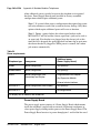
Note: When upgrading software, memory upgrades may be required on
the Signaling Server, the Call Server, or both.
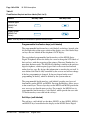
System migration
When particular Meridian 1 systems are upgraded to run CS 1000
Release 4.5 software and configured to include a Signaling Server, they
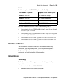
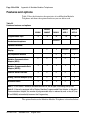
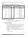
become CS 1000M systems. Table 1 lists each Meridian 1 system that
supports an upgrade path to a CS 1000M system.
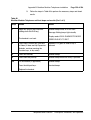
Table 1
Meridian 1 systems to CS 1000M systems (Part 1 of 2)
553-3001-367
This Meridian 1 system...
Maps to this CS 1000M system
Meridian 1 PBX 11C Chassis
CS 1000M Chassis
Meridian 1 PBX 11C Cabinet
CS 1000M Cabinet
Standard 3.00
August 2005
About this document
Page 21 of 504
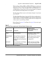
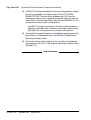
Table 1
Meridian 1 systems to CS 1000M systems (Part 2 of 2)
This Meridian 1 system...
Maps to this CS 1000M system
Meridian 1 PBX 51C
CS 1000M Half Group
Meridian 1 PBX 61C
CS 1000M Single Group
Meridian 1 PBX 81
CS 1000M Multi Group
Meridian 1 PBX 81C
CS 1000M Multi Group
For more information, see one or more of the following NTPs:
•
Communication Server 1000M and Meridian 1: Small System Upgrade
Procedures (553-3011-258)
•
Communication Server 1000M and Meridian 1: Large System Upgrade
Procedures (553-3021-258)
•
Communication Server 1000S: Upgrade Procedures (553-3031-258)
•
Communication Server 1000E: Upgrade Procedures (553-3041-258)
Intended audience
This document is intended for individuals responsible for installing,
configuring, operating, administering, and troubleshooting Meridian
proprietary telephones, attendant consoles and add-on modules, and
engineering and configuring digital telephone lines.
Conventions
Terminology
In this document, the following systems are referred to generically as
“system”:
•
Communication Server 1000S (CS 1000S)
•
Communication Server 1000M (CS 1000M)
Telephones and Consoles
Description, Installation, and Operation
Page 22 of 504
About this document
•
Communication Server 1000E (CS 1000E)
•
Meridian 1
The following systems are referred to generically as “Small System”:
•
Communication Server 1000M Chassis (CS 1000M Chassis)
•
Communication Server 1000M Cabinet (CS 1000M Cabinet)
•
Meridian 1 PBX 11C Chassis
•
Meridian 1 PBX 11C Cabinet
The following systems are referred to generically as “Large System”:
•
Communication Server 1000M Half Group (CS 1000M HG)
•
Communication Server 1000M Single Group (CS 1000M SG)
•
Communication Server 1000M Multi Group (CS 1000M MG)
•
Meridian 1 PBX 51C
•
Meridian 1 PBX 61C
•
Meridian 1 PBX 81
•
Meridian 1 PBX 81C
Related information
This section lists information sources that relate to this document.
NTPs
The following NTPs are referenced in this document:
553-3001-367
•
Spares Planning (553-3001-153)
•
Equipment Identification (553-3001-154)
•
Circuit Card: Description and Installation (553-3001-211)
•
Features and Services (553-3001-306)
•
Software Input/Output: Administration (553-3001-311)
•
Attendant PC: Description, Installation, and Operation (553-3001-320)
Standard 3.00
August 2005
About this document
Page 23 of 504
•
Software Input/Output: System Messages (553-3001-411)
•
Software Input/Output: Maintenance (553-3001-511)
•
Communication Server 1000M and Meridian 1: Small System Upgrade
Procedures (553-3011-258)
•
Communication Server 1000M and Meridian 1: Large System Upgrade
Procedures (553-3021-258)
•
Analog Terminal Adapter Quick Reference Card
•
PC Console Interface Unit Installation Guide
•
PC Console Interface Unit Quick Reference Guide
•
Installing the Analog Terminal Adapter
•
Meridian Digital Telephones: M3901, M3902, M3903, M3904 User
Guide
•
Meridian Digital Telephones: M3902, M3903, M3904 Quick Reference
Guide
•
Meridian Digital Telephone: M3905 Call Center User Guide
•
Nortel M2016S Secure Set Quick Reference Guide
•
Nortel M2016S Secure Set User Guide
For information on IP Phones, refer to IP Phones: Description, Installation,
and Operation (553-3001-368).
Online
To access Nortel documentation online, click the Technical Documentation
link under Support on the Nortel home page:
http://www.nortel.com
CD-ROM
To obtain Nortel documentation on CD-ROM, contact your Nortel customer
representative.
Telephones and Consoles
Description, Installation, and Operation
Page 24 of 504
About this document
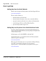
How to get Help
Getting Help from the Nortel Web site
The best source of support for Nortel products is the Nortel Support Web site:
www.nortel.com/support
This site enables customers to:
•
download software and related tools
•
download technical documents, release notes, and product bulletins
•
sign up for automatic notification of new software and documentation
•
search the Support Web site and Nortel Knowledge Base
•
open and manage technical support cases
Getting Help over the phone from a Nortel Solutions Center
If you have a Nortel support contract and cannot find the information you
require on the Nortel Support Web site, you can get help over the phone from
a Nortel Solutions Center.
In North America, call 1-800-4NORTEL (1-800-466-7865).
Outside North America, go to the Web site below and look up the phone
number that applies in your region:
www.nortel.com/callus
When you speak to the phone agent, you can reference an Express Routing
Code (ERC) to more quickly route your call to the appropriate
support specialist. To locate the ERC for your product or service, go to:
www.nortel.com/erc
553-3001-367
Standard 3.00
August 2005
About this document
Page 25 of 504
Getting Help through a Nortel distributor or reseller
If you purchased a service contract for your Nortel product from a distributor
or authorized reseller, you can contact the technical support staff for that
distributor or reseller.
Telephones and Consoles
Description, Installation, and Operation
Page 26 of 504
553-3001-367
About this document
Standard 3.00
August 2005
102
Page 27 of 504
Attendant consoles
Contents
This section contains information on the following topics:
Introduction . . . . . . . . . . . . . . . . . . . . . . . . . . . . . . . . . . . . . . . . . . . . . .
28
Engineering codes . . . . . . . . . . . . . . . . . . . . . . . . . . . . . . . . . . . . . . . . .
29
Features . . . . . . . . . . . . . . . . . . . . . . . . . . . . . . . . . . . . . . . . . . . . . . . . .
Busy Lamp Field/Console Graphics Module . . . . . . . . . . . . . . . . . .
Display backlight power supply option . . . . . . . . . . . . . . . . . . . . . .
DSS-9000 Direct Station Select/Busy Lamp Field . . . . . . . . . . . . .
Attendant Supervisory Module. . . . . . . . . . . . . . . . . . . . . . . . . . . . .
31
32
44
44
44
Physical description. . . . . . . . . . . . . . . . . . . . . . . . . . . . . . . . . . . . . . . .
Dimensions . . . . . . . . . . . . . . . . . . . . . . . . . . . . . . . . . . . . . . . . . . . .
Keyboard layout . . . . . . . . . . . . . . . . . . . . . . . . . . . . . . . . . . . . . . . .
Display screen messages . . . . . . . . . . . . . . . . . . . . . . . . . . . . . . . . .
Display screen messages . . . . . . . . . . . . . . . . . . . . . . . . . . . . . . . . .
Connections . . . . . . . . . . . . . . . . . . . . . . . . . . . . . . . . . . . . . . . . . . .
Local console controls . . . . . . . . . . . . . . . . . . . . . . . . . . . . . . . . . . .
48
48
51
55
55
56
56
Wiring . . . . . . . . . . . . . . . . . . . . . . . . . . . . . . . . . . . . . . . . . . . . . . . . . .
Installing wiring . . . . . . . . . . . . . . . . . . . . . . . . . . . . . . . . . . . . . . . .
57
57
Installation. . . . . . . . . . . . . . . . . . . . . . . . . . . . . . . . . . . . . . . . . . . . . . .
Normal operating ranges . . . . . . . . . . . . . . . . . . . . . . . . . . . . . . . . .
Packing and unpacking. . . . . . . . . . . . . . . . . . . . . . . . . . . . . . . . . . .
Installation and removal . . . . . . . . . . . . . . . . . . . . . . . . . . . . . . . . . .
Installing the M2250 attendant console . . . . . . . . . . . . . . . . . . . . . .
Removing the M2250 attendant console . . . . . . . . . . . . . . . . . . . . .
59
59
59
60
60
61
Telephones and Consoles
Description, Installation, and Operation
Page 28 of 504
Attendant consoles
Removing the M2250 attendant console top cover . . . . . . . . . . . . .
Installing the M2250 attendant console top cover . . . . . . . . . . . . . .
Performing a loopback test . . . . . . . . . . . . . . . . . . . . . . . . . . . . . . .
Designating keys on the M2250 attendant console . . . . . . . . . . . . .
Cross-connecting attendant consoles . . . . . . . . . . . . . . . . . . . . . . . .
62
63
64
64
68
Operation . . . . . . . . . . . . . . . . . . . . . . . . . . . . . . . . . . . . . . . . . . . . . . .
M2250 configurations . . . . . . . . . . . . . . . . . . . . . . . . . . . . . . . . . . .
Attendant PC requirements . . . . . . . . . . . . . . . . . . . . . . . . . . . . . . .
M2250 feature key modes . . . . . . . . . . . . . . . . . . . . . . . . . . . . . . . .
M2250 console diagnostics . . . . . . . . . . . . . . . . . . . . . . . . . . . . . . .
M2250 failure codes. . . . . . . . . . . . . . . . . . . . . . . . . . . . . . . . . . . . .
M2250 feature operation . . . . . . . . . . . . . . . . . . . . . . . . . . . . . . . . .
77
77
78
79
81
87
89
Introduction
Attendant consoles are designed to assist in placing and extending calls into
and out of a telephone switching system. The console is operated by an
attendant who is the human interface between the system and the users.
The M2250 attendant console is a stand-alone, digital attendant console
designed for telephone traffic control in the CS 1000 and Meridian 1. A
Digital Line Card (DLC) connects the M2250 to the system.
The PC-based Console application software allows all functions supported by
the M2250 to be performed on a computer workstation within a Windows
95®, Windows 98®, Windows 2000®, or Windows NT® operating system
environment. The PC-based Console application operates with the PC
Console Interface Unit (PCCIU). The PCCIU is typically installed under the
attendant’s PC monitor, and provides connection to the Main Distribution
Frame (MDF) and PC communications port. The PCCIU is configured as an
M2250 attendant console in LD 12. Refer to Software Input/Output:
Administration (553-3001-311) for configuration information
In the North America, Asia Pacific and CALA market regions, the PCCIU
and the Attendant PC software are available as a bundled package. In the
EMEA market region, the PCCIU is available on its own or with a separate
PC software application called SMILE.
553-3001-367
Standard 3.00
August 2005
Attendant consoles
Page 29 of 504
For more information on Attendant PC and the PCCIU, refer to the following
documents:
•
Attendant PC: Description, Installation, and Operation (553-3001-320)
•
PC Console Interface Unit Installation Guide
•
PC Console Interface Unit Quick Reference Guide
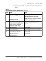
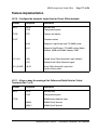
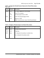
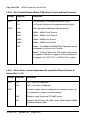
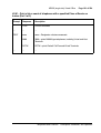
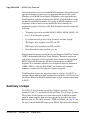
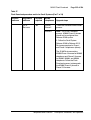
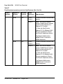
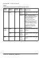
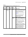
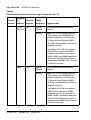
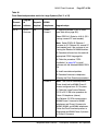
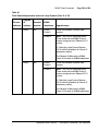
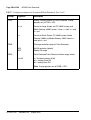
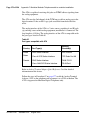
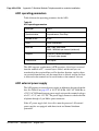
Engineering codes
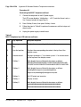
Refer to Table 2 for engineering codes for available M2250 attendant console
models and related equipment. For ordering information, refer to Equipment
Identification (553-3001-154). For EMEA codes, please contact your local
Nortel representative.
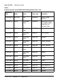
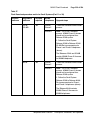
Table 2
Engineering codes for the M2250 and related equipment (Part 1 of 3)
Engineering
code
Model
Color
Order code
Availability
NT3G40BB-35
BLF/CGM
Chameleon
A0652760
CALA, Spain, US
NT3G41BB-35
BLF/CGM
Chameleon
Grey
A0652758
APAC, Canada
NT3G41BB-98
BLF/CGM
Dark Grey
A0652759
APAC
NT3G42BA-35
BLF/CGM
N/A
A0642991
Africa, Australia,
Austria, Belgium, CIS,
Denmark, Europe,
Finland, France,
Germany, Greece,
Holland, Ireland,
Middle East, Norway,
Portugal, Sweden,
Switzerland, Turkey,
UK
NT3G42BA-93
BLF/CGM
Dolphin
A0656519
Australia, UK
Telephones and Consoles
Description, Installation, and Operation
Page 30 of 504
Attendant consoles
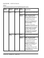
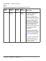
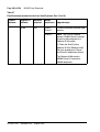
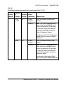
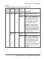
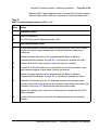
Table 2
Engineering codes for the M2250 and related equipment (Part 2 of 3)
Engineering
code
Model
Color
Order code
Availability
NT3G42BA-98
BLF/CGM
N/A
A0642994
Finland, France,
Germany
NT6G00AF-35
M2250
Chameleon
Grey
A0393450
Africa, APAC, CALA,
CIS, Greece, Ireland,
Middle East, NA,
Portugal, Turkey
NT6G40BA-35
M2250
Chameleon
Grey
A0642786
Switzerland
NT6G41BB-35
M2250
Chameleon
Grey
A0642787
APAC, Norway
NT6G42BC-35
M2250
Chameleon
Grey
A0642788
Denmark
NT6G43BA-35
M2250
Chameleon
Grey
A0642789
Finland, Germany
NT6G43BA-98
M2250
Dark Grey
A0642790
Finland, Germany
NT6G44BA-35
M2250
Chameleon
Grey
A0642791
Austria
NT6G45BA-35
M2250
Chameleon
Grey
A0642792
Belgium
NT6G47BB-35
M2250
Chameleon
Grey
A0642793
France
NT6G47BB-98
M2250
Dark Grey
A0642794
France
NT6G48BC-35
M2250
Chameleon
A0642795
UK
NT6G48BC-93
M2250
Dolphin
A0642796
New Zealand, UK
NT6G50BA-35
M2250
Chameleon
A0642797
Australia
NT6G50BA-93
M2250
Dolphin
A0642798
Australia
553-3001-367
Standard 3.00
August 2005
Attendant consoles
Page 31 of 504
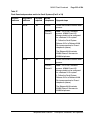
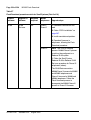
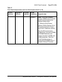
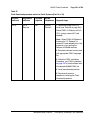
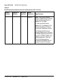
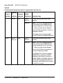
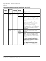
Table 2
Engineering codes for the M2250 and related equipment (Part 3 of 3)
Engineering
code
Model
Color
Order code
Availability
NT6G53BB-35
M2250
Chameleon
A0655900
Holland
NT6G55BA-35
M2250
Chameleon
Grey
A0642799
Spain
NT6G56BB-35
M2250
Chameleon
Grey
A0642802
Sweden
NT6G57BA-35
M2250
Chameleon
Grey
A0642803
Italy
NT6G57BA-98
M2250
Dark Grey
A0642804
Italy
NT3G30AA-35
Adjustable
stand
Chameleon
gray (ash)
A0348780
Global
NT3G30AA-98
Adjustable
stand
BTS dark gray
A0348778
Global
NT7G10AA
Attendant
Supervisory
Module (ASM)
N/A
A0366221
Global
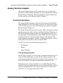
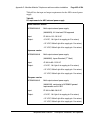
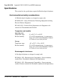
Features
The M2250 has the following features:
•
A four-line, 40 character, liquid crystal display (LCD) with backlighting.
Power, including backlighting, is maintained during building power
failures with the system’s battery backup, if equipped.
•
Angle adjustment of the display screen, which can be tilted through 90°
from horizontal to fully vertical.
•
Scrolling control of lines 2 and 3 of the display screen.
•
In Shift mode, the M2250 can have up to 20 Trunk Group Busy (TGB)
keys.
Telephones and Consoles
Description, Installation, and Operation
Page 32 of 504
Attendant consoles
•
In Shift mode, the M2250 can have up to 10 extra flexible feature keys
for a total of 20.
•
An optional supporting stand that can be adjusted to nine different
positions.
•
A handset and headset volume slider control, situated below the dial pad.
•
A physical connection to a serial data port through a subminiature D-type
female connector on the console back wall. This permits connection of
the console to the serial port of a personal computer.
•
An optional Busy Lamp Field/Console Graphics Module (BLF/CGM),
which displays the status of up to 150 consecutive extensions (SBLF) or
any group of 100 extensions within the system (EBLF) and has many text
and graphics capabilities.
•
An optional Attendant Supervisory Module (ASM) can be installed.
•
Supports transmission level adjustment to meet international
requirements by accepting and processing downloaded information from
the system (when this messaging is supported in software). The
transmission level can be adjusted to one of 16 different levels.
•
Multi-language selection.
•
Menus for local console features (Options menu) and diagnostics
(Diagnostics menu).
•
Code blue or emergency relay (associated with ICI 0).
•
Time and date system download.
•
Alert tone volume and frequency selection.
•
Electret or carbon transmitter support.
•
Power Fail Transfer switch.
•
Keyclick.
Busy Lamp Field/Console Graphics Module
The Busy Lamp Field/Console Graphics Module (BLF/CGM) can be added
to an M2250 attendant console.
553-3001-367
Standard 3.00
August 2005
Attendant consoles
Page 33 of 504
The BLF/CGM can do the following:
•
display the status (busy or idle) of up to 150 consecutive extensions
within the system Standard Busy Lamp Field (SBLF)
•
display the status (busy or idle) of any hundred group of DNs within the
system Enhanced Busy Lamp Field (EBLF)
•
display which attendant console is the supervisory console and which
consoles are active
•
display supplementary information about individual extensions, such as
the reason the person is away (business, vacation, or illness), when the
person is due to return, and an alternate extension where calls to the
person should be directed
•
display a company logo
•
display graphics
•
display text in any one of eight languages
•
have its screen contrast adjusted for easy viewing
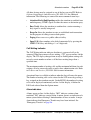
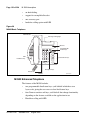
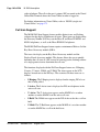
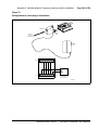
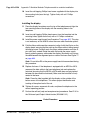
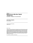
Power requirements
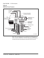
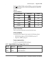
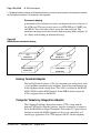
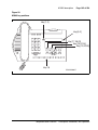
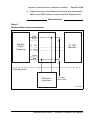
The BLF/CGM obtains its power through the attendant console. See Figure 1
on page 35. The requirements are as follows:
•
a reference ground line (0 V)
•
power source of 5 V for the CMOS electronics that control the Lamp
Field Array module (c. 50 mA)
•
power source of –12 V for the display of the Console Graphics Module
(c. 10 mA)
•
backlighting power
The BLF/CGM has a battery that provides backup power to maintain the
Supplementary Information when the console is powered down. The battery
lifetime is five years. To replace the battery, return the BLF/CGM to the
supplier.
Telephones and Consoles
Description, Installation, and Operation
Page 34 of 504
Attendant consoles
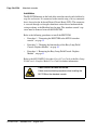
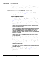
Installation
The BLF/CGM mounts on the back of the attendant console and is held on by
snap-fits and screws. It is connected to the console using a 16-way connector
that is located on the keyboard Printed Circuit Board (PCB). This connector
is accessed through a rectangular knockout section located underneath the
casing overhang at the Meridian logo location. The attendant console’s top
cover must be removed to install the BLF/CGM.
Refer to the following procedures to install the BLF/CGM:
•
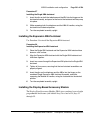
Procedure 1, “Connecting the BLF/CGM to the M2250 attendant
console”, on page 35
•
Procedure 2, “Checking the functionality of the Busy Lamp Field/
Console Graphics Module”, on page 42
•
Procedure 3, “Removing the Busy Lamp Field/Console Graphics
Module”, on page 43
Refer to the M1250/M2250 Attendant Console User Guide or the Busy Lamp
Field/Console Graphics Module User Guide for further information.
CAUTION WITH ESDS DEVICES
Follow normal antistatic precautions when installing the
BLF/CGM on the attendant console.
553-3001-367
Standard 3.00
August 2005
Attendant consoles
Page 35 of 504
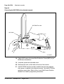
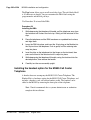
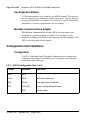
Figure 1
Busy Lamp Field/Console Graphics Module on the M2250 attendant console
BLF/CGM
M2250 Attendant Console
553-AAA1718.EPS
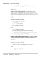
Procedure 1
Connecting the BLF/CGM to the
M2250 attendant console
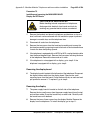
1
Disconnect the main power/system cable from the rear of the attendant
console, and remove the handset jack plug from the side.
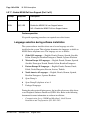
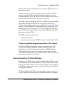
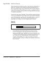
2
Move the adjustable display to the down position to protect it from
damage while installing the BLF/CGM. Move the volume slider switch to
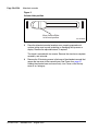
the far left. See Figure 2 on page 36.
Telephones and Consoles
Description, Installation, and Operation
Page 36 of 504
Attendant consoles
Figure 2
Volume slider position
Move Volume Slider
to left-most position
3
553-AAA0626
Place the attendant console facedown on a properly prepared work
surface, taking care to avoid scratching or damaging the top cover or
display. Remove the adjustable stand, if required.
The stand is secured with four screws. Remove the stand as a complete
assembly, and set aside.
4
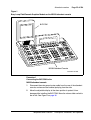
553-3001-367
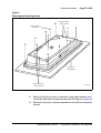
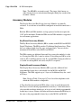
Remove the 12 fastening screws in the base of the attendant console that
secure the top cover to the console base. See Figure 3 on page 37.
Holding the console base and cover firmly, turn it over so that the top
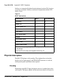
cover is on, facing up.
Standard 3.00
August 2005
Attendant consoles
Page 37 of 504
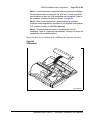
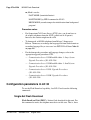
Figure 3
Removing the fastening screws
Do Not Remove
These Screws
Remove These
12 Screws
Polystyrene
Foam Sheet
Do Not Remove
These Screws
553-AAA0627
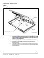
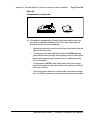
5
Raise and hold the top cover to remove the single cable connector only.
The alerter cable does not need to be removed. See Figure 4 on page 38.
6
Remove the top cover, and place it upside down to the left of the attendant
console.
Telephones and Consoles
Description, Installation, and Operation
Page 38 of 504
Attendant consoles
Figure 4
Removing the top cover
Top cover
Base
Remove flat cable
553-AAA1719.EPS
553-3001-367
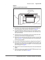
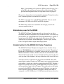
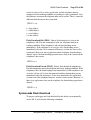
7
Remove the knockout section on the back of the attendant console (see
Figure 5 on page 39) with a small screwdriver or similar tool. Remove any
remnants of the breakaway tags.
8
Feed the flat ribbon cable for the Busy Lamp Field/Console Graphics
Module (BLF/CGM) through the knockout hole in the base of the
attendant console.
9
Hold the BLF/CGM unit over the console in a vertical position, ensuring
that the two locators on the bottom bracket of the BLF/CGM are located
in the knockout hole.
Standard 3.00
August 2005
Attendant consoles
Page 39 of 504
Figure 5
Attendant console knockout section
Knockout Section
(Clean Away 6 Tags)
Base
553-AAA0629
10 Push down on the attendant console, while holding the BLF/CGM unit,
until the two locators snap into place. See Figure 6 on page 40.
11 Fit the BLF/CGM ribbon cable onto the top cover circuit board, into the
flexible strip connector J4 (so that the blue line on the cable faces away
from the circuit board).
12 Hold the top cover over the attendant console and reconnect the cable
connector(s) onto the base of the attendant console.
13 Place the top cover on the console. Slide it back and down into place. See
Figure 7 on page 41. Check that all the cables are in the correct positions
and that none are trapped.
14 Push the BLF/CGM display into position by rotating it back (see Figure 7).
15 Ensuring that the volume slider is fully engaged in the correct slider, hold
the top cover and console base firmly together. Turn the assembly upside
down. See Figure 8 on page 42.
16 Reinsert the 12 screws that secure the top cover to the console base and
tighten.
17 Insert the two new screws supplied with the BLF/CGM that attach it to the
base, and tighten. See Figure 8 on page 42.
Telephones and Consoles
Description, Installation, and Operation
Page 40 of 504
Attendant consoles
Figure 6
Connecting the BLF/CGM to the attendant console
BLF/CGM Flat cable
BLF/CGM
Base
553-AAA0630
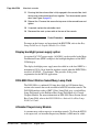
18 Cable in BLF power at the local Main Distribution Frame (MDF) as per
M2250 cross-connections.
19 If required, replace the adjustable stand.
20 Reconnect the main system cable to the rear of the console.
21 If the BLF/CGM has been correctly installed, the main menu appears
when power is supplied to the attendant console. Test the BLF/CGM by
selecting a menu option. Refer to Busy Lamp Field/Console Graphics
Module User Guide for programming information.
553-3001-367
Standard 3.00
August 2005
Attendant consoles
Page 41 of 504
22 Define the Busy Lamp Field in the system database. Refer to Features
and Services (553-3001-306).
23 Test the Busy Lamp Field features using M1250/M2250 Attendant
Console User Guide.
Figure 7
Positioning the top cover and the BLF/CGM
BLF/CGM
Rotate Back
Slide Back
and Down
Top Cover
Base
553-AAA0632
Telephones and Consoles
Description, Installation, and Operation
Page 42 of 504
Attendant consoles
Figure 8
Attaching the top cover to the attendant console base and BLF/CGM
Fit 2 new screws
Re-Insert
12 Screws
Polystyrene foam sheet
553-AAA0633
End of Procedure
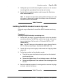
Procedure 2
Checking the functionality of the
Busy Lamp Field/Console Graphics Module
Use this procedure to check the functionality of the BLF/CGM. Once in this
menu, the dial pad is in CGM mode. When any dial pad keys are pressed,
except the pound (#) key, the keys are echoed on the BLF/CGM.
553-3001-367
1
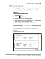
From Diagnostics menu 1, press 5.
2
Press keys 0 through 9 and the asterisk (*) on the dial pad. Check the
CGM to see that they are echoed.
Standard 3.00
August 2005
Attendant consoles
3
Page 43 of 504
Press the pound (#) to exit and return to Diagnostics menu 1.
End of Procedure
Procedure 3
Removing the Busy Lamp
Field/Console Graphics Module
1
Disconnect the main power/system cable from the rear of the attendant
console, and remove the handset jack plug from the side.
2
Move the adjustable display to the down position to protect it from
damage while removing the BLF/CGM. Also move the volume slider
switch to the far left (see Figure 2 on page 36).
3
Place the attendant console facedown on a properly prepared work
surface, taking care to avoid scratching or damaging the top cover or
display. Remove the adjustable stand, if required.
The stand is secured with four screws. Remove the stand as a
complete assembly, and set it aside.
4
Remove the 12 fastening screws in the base of the attendant console that
secure the top cover to the console base. See Figure 3 on page 37.
Remove the two screws securing the BLF/CGM to the base of the
attendant console.
5
Holding the console base and cover firmly, turn it back over so that the top
cover is on, facing up.
6
Raise and hold the top cover to remove the single cable connector only.
The alerter cable does not need to be removed (see Figure 4 on page 38).
7
Unplug the BLF/CGM ribbon cable from the attendant console.
8
Remove the top cover and place it upside down to the left of the attendant
console.
9
Pull back the snap-fits on the BLF/CGM to disengage the BLF/CGM from
the attendant console.
10 Place the top cover on the console. Slide it back and down into place (see
Figure 7 on page 41). Reconnect all cables in the correct positions, and
make sure that none are trapped.
Telephones and Consoles
Description, Installation, and Operation
Page 44 of 504
Attendant consoles
11 Ensuring that the volume slider is fully engaged in the correct slider, hold
the top cover and console base firmly together. Turn the assembly upside
down (see Figure 8 page 42).
12 Reinsert the 12 screws that secure the top cover to the console base and
tighten.
13 If required, replace the adjustable stand.
14 Reconnect the main system cable to the rear of the console.
End of Procedure
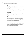
For more on the features and operation of the BLF/CGM, refer to the Busy
Lamp Field/Console Graphics Module User Guide.
Display backlight power supply option
An optional 16 V DC power supply (A0367601) can be installed to the Main
Distribution Frame (MDF) to improve the backlight brightness of the BLF/
CGM display.
The display backlight power supply must be cabled in at the local MDF at a
maximum of 120 ft (36 m) from the attendant console when the BLF/CGM is
installed (A0367601 – Transformer). This provides all the power
requirements for the M2250 applications.
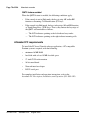
DSS-9000 Direct Station Select/Busy Lamp Field
The DSS-9000 is a combined 150-lamp busy field and 150-button direct
station select console that can be attached to an M2250 attendant console. The
DSS-9000 emulates either a QMT-3 Busy Lamp Field array (standard Busy
Lamp Field mode) or the Enhanced Busy Lamp Field Mode of a Console
Graphics Module. For more information on DSS-9000 Direct Station Select/
Busy Lamp Field, refer to the DSS-9000 Direct Station Select/Busy Lamp
Field User Guide.
Attendant Supervisory Module
A customer may wish to supervise an attendant console. To allow the M2250
to be supervised, an Attendant Supervisory Module (ASM) must be added.
553-3001-367
Standard 3.00
August 2005
Attendant consoles
Page 45 of 504
An attendant console configured as a supervisor does not need the ASM
installed.
To accept the ASM, the minimum vintage M2250 attendant console is
M2250AD. To fully support the ASM, the minimum vintage BLF/CGM is
AB. The third PWR TN must be programmed and wired out to support the
ASM. See Figure 17 on page 71.
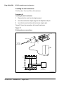
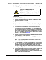
Follow the steps in Procedure 4 to install an ASM on an M2250 attendant
console.
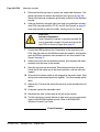
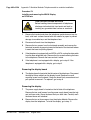
Procedure 4
Installing an Attendant Supervisory Module
on an M2250 attendant console
CAUTION WITH ESDS DEVICES
Damage to Equipment
Before handling internal set components, discharge
static electricity from hands and tools by touching
any grounded metal surface or conductor.
1
Disconnect the main power/system cable from the rear of the attendant
console, and remove the handset jack plug from the side.
2
Move the adjustable display to the down position to protect it from
damage while installing the ASM. Move the volume slider switch to the
left-most position.
3
Place the attendant console facedown on a properly prepared work
surface, taking care to avoid scratching or damaging the top cover or
display. Remove the adjustable stand, if equipped.
The stand is secured with four screws. Loosen the screws and remove
the stand as a complete assembly, and set aside.
4
Remove the 12 fastening screws in the base of the attendant console that
secure the top cover to the console base (see Figure 3 on page 37).
Holding the console base and cover firmly, turn it back over so that the top
cover is on, facing up.
Telephones and Consoles
Description, Installation, and Operation
Page 46 of 504
Attendant consoles
5
Raise and hold the top cover to remove the single cable connector. The
alerter cable does not need to be removed (see Figure 4 on page 38).
Remove the top cover and place it upside down to the left of the attendant
console.
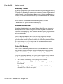
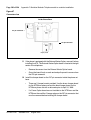
6
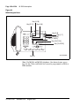
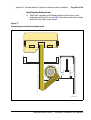
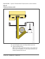
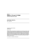
Holes are located in the upper right-hand side of the attendant console’s
main PCB, near grid positions D1, D5, and A5. See Figure 9 on page 47.
Insert one standoff in each of the holes, twisting it until it is secure.
CAUTION
Damage to Equipment
Once a standoff is inserted, it cannot be removed. Be
sure to place each standoff in the correct hole on the
main PCB, as shown in Figure 9 on page 47.
7
Position the ASM board over the J3 connector on the console’s main
PCB. Align the holes on the ASM board with the standoffs, and carefully
work the ASM pin connector onto connector J3 until firmly seated. See
Figure 9 on page 47.
8
Hold the top cover over the attendant console, and reconnect the cable
connector onto the base of the console.
9
Place the top cover on the console. Slide it back and down into place.
Check that all the cables are in the correct positions, and that none are
trapped.
10 Ensure that the volume switch is fully engaged in the correct slider. Hold
the top cover and console base firmly together. Turn the assembly upside
down.
11 Reinsert the 12 screws that secure the top cover to the console base and
tighten.
12 If required, replace the adjustable stand.
13 Reconnect the main system cable to the rear of the console.
14 Test the supervisory console feature to make sure you can now properly
supervise the M2250 attendant console. Refer to M1250/M2250
Attendant Console User Guide.
End of Procedure
553-3001-367
Standard 3.00
August 2005
Attendant consoles
Page 47 of 504
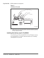
Figure 9
Identifying the correct grid positions on the main PCB and attaching the ASM
Grid marks
9
5
A
B
Pin connector
C
J3 connector
Attendant Supervisory Module
D
Insert Standoffs here
M2250 main PCB (cutaway)
553-AAA0634
Telephones and Consoles
Description, Installation, and Operation
Page 48 of 504
Attendant consoles
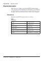
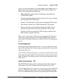
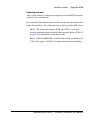
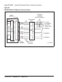
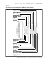
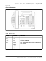
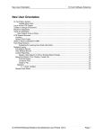
Physical description
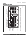
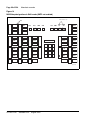
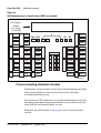
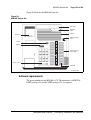
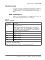
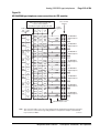
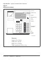
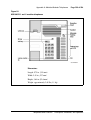
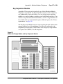
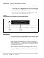
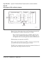
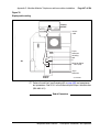
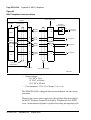
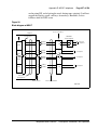
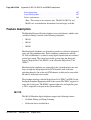
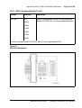
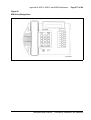
Figure 10 on page 49 shows a top view of the M2250 attendant console
layout. The user-accessible components are labeled using a row/column grid
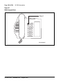
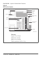
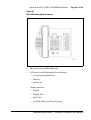
arrangement. Figure 11 on page 50 shows rear, left side, and bottom views of
the console. These illustrations show where to find the various components.
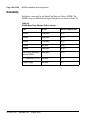
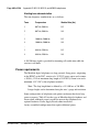
Dimensions
Dimensions of the M2250 attendant console are as follows:
Table 1
Dimensions
553-3001-367
Width
425 mm (16.75 in.)
Depth
245 mm (9.6 in.)
Height (front)
25 mm (1 in.)
Height (back)
65 mm (2.5 in.)
Height (with display screen panel up)
115 mm (4.5 in.)
Weight
approximately 2.75 kg (6 lbs)
Standard 3.00
August 2005
Telephones and Consoles
0
1
3
2
6
5
4
7
9
8
AI
AK
A
BK
CI
(3)
or
DI/EI
C (2)
CK
(1)
C/H
Display line 1
Display line 2
Display line 3
Display line 4
(5)
(6)
*
0
8
5
4
7
3
2
1
#
9
6
D2
D1
D0
Directory Number
(4)
Display 1
Display 2
EI
(7) (8)
F
FI
FK
Power Fail Transfer Switch
(in base of console)
EK
Hold
Shift
Conf
RL.Des
RL.Src
EX.Des
EX.Scr
RS-232 Connector for
connection to PC with Monitor
Slider Control for Handset or Headset Volume Adjustments
BI
B
Display screen (can be tilted upwards)
25-pin subminiature D-type male
connector for cable connecting
console to distributing frame
553-AAA0566
Note: Rows and columns are labeled with numbers and letters respectively in order to allow textual references when identifying the
location of specific components. In the column designations, the letter I stands for indicators, and the letter K signifies keystrips.
Columns
Backlighting
ON/OFF
Slider Switch
Handset or
headset jacks
(in both sidesof
console)
Rows
Arbitrary Icon key numbering for test identification
purposes only (not designated on the console)
Attendant consoles
Page 49 of 504
Figure 10
M2250 attendant console – top view
Description, Installation, and Operation
Page 50 of 504
Attendant consoles
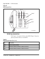
Figure 11
M2250 attendant console – rear, left side, and bottom views
Display panel (can be tilted upwards)
Handset/Headset jacks
........
.......
Handset/Headset jacks
.......
.......
Protective plastic cover to be installed when
connector is not in use
RS-232 female connector for connection
to PC with monitor (data port)
Knockout for access
to J4 connector
(BLF/CGM)
25-pin subminiature D-type male connector for cable
connecting console to distributing frame
Rear view
Handset/Headset jacks
(same on opposite side)
Backlighting ON/OFF slider switch
Left side view
Front edge of console
Power Fail Transfer
switch (PFT)
On
Backlighting
slider switch
Off
Handset/Headset jacks
Adjustable standscrew
mounting point (total of 4)
Knockout for access
to J4 connector
(BLF/CGM)
Bottom view
553-3001-367
Standard 3.00
August 2005
RS-232 female connector
25-pin D-type male connector
553-AAA0575
Attendant consoles
Page 51 of 504
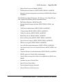
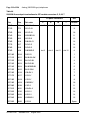
Keyboard layout
Refer to Table 3 for the description of keys and Figure 10 on page 49 and
Figure 11 on page 50 for the location of switches and keys mentioned in this
section.
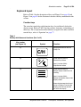
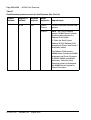
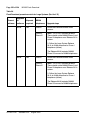
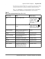
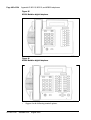
Function keys
The attendant console has eight function keys, located directly below the
display screen. Refer to Table 3 for the positions, functions, and markings of
these keys. For an explanation of the functions assigned to the other attendant
console keys, refer to “Operation” on page 77.
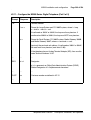
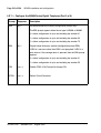
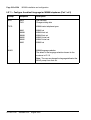
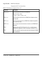
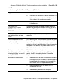
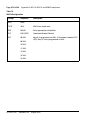
Table 3
Softkey definitions and functions (Part 1 of 3)
Key number
(see Figure 10)
Symbol
(1)
C/H
(2)
Function
Centralized Attendant Service
(CAS) File
Prime function (normal):
Position Busy feature
Level 1 function (Shift):
Night Service feature
(3)
Prime function (normal):
Selects display screen line 2 for
scrolling.
Level 1 function (Shift):
Selects the Options menu on the
display screen.
Alternating between the idle and
active call display. From the idle
display, press this key to show
the active call display.
Telephones and Consoles
Description, Installation, and Operation
Page 52 of 504
Attendant consoles
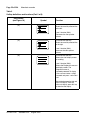
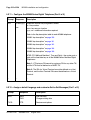
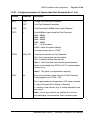
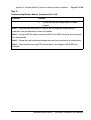
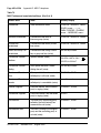
Table 3
Softkey definitions and functions (Part 2 of 3)
Key number
(see Figure 10)
Symbol
(4)
Function
Prime function (normal):
Scrolls the currently selected line
to the left.
Level 1 function (Shift):
Decreases the alert speaker
volume.
(5)
Prime function (normal):
Scrolls the currently selected line
to the right.
Level 1 function (Shift):
Increases the alert speaker
volume.
(6)
Prime function (normal):
Selects line 3 on display screen
for scrolling.
Level 1 function (Shift):
Selects the Diagnostics menu on
the display screen. The
Diagnostics menu is
password-protected. To display
it, the user must enter a 4-digit
password and press * on the dial
pad.
Alternating between the idle and
active call display. From the
active call display, press this key
to show the idle display.
553-3001-367
Standard 3.00
August 2005
Attendant consoles
Page 53 of 504
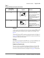
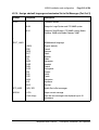
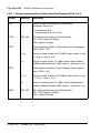
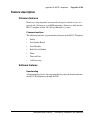
Table 3
Softkey definitions and functions (Part 3 of 3)
Key number
(see Figure 10)
Symbol
(7)
Function
Prime function (normal):
Signal Source feature key
Level 1 function (Shift and Conf/
Busy Lamp Field key):
Used with the Busy Lamp Field/
Console Graphics Module, as
CGM key.
(8)
Prime function (normal):
Signal Destination feature key
Level 1 function (Shift):
Used with the Busy Lamp Field/
Console Graphics Module, as the
Mode key.
Switches
A slider control, located below the dial pad, between columns DI/EI and FI,
controls the handset and headset receive volume level. See Figure 10 on
page 49.
A Power Fail Transfer (PFT) switch is located in the baseplate. See Figure 11
on page 50. Both the line connector and the RS-232 connector for the PC port
are located at the back of the console.
Shift key
The Shift key is positioned in column FK, row 1, just above the Hold key. See
Figure 10 onpage 49. It is used to access Level 1 mode functions.
Handset and headset jacks
Two pairs of jacks are provided for plugging in handsets or headsets. The
jacks are located on both sides of the console beneath the faceplate in the
recessed area shown by the arrows. See Figure 10 on page 49. The console
Telephones and Consoles
Description, Installation, and Operation
Page 54 of 504
Attendant consoles
accepts both carbon and electret handsets or headsets and automatically
adapts itself to each type.
Note: Electret headsets and handsets are polarity sensitive and must be
correctly inserted into the jack.
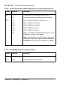
LCD indicators
The LCD indicators on the M2250 display triangular symbols that normally
point towards the key with which they are associated. Certain keys in the
QMT2 mode of operation and loop keys have two LCDs associated with each
key instead of one.
Every LCD can flash at 30, 60, or 120 impulses per minute (ipm). Refer to
“Operation” on page 77 for more details.
The M2250 attendant console has 10 additional flexible features. These are
programmed in LD 12 and accessed using the Shift key.
553-3001-367
Standard 3.00
August 2005
Attendant consoles
Page 55 of 504
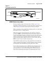
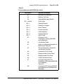
Display screen messages
Source information appears on line 2 of the display screen. Destination
information appears on line 3 of the display screen.
The status messages listed below appear on line 4 of the display screen panel.
— MN
(minor alarm)
— MJ
(major alarm)
— C/H
(CAS/History File)
— CW
(Call Waiting)
— BUSY
(Position Busy)
— NIGHT
(Night Service)
— IDLE
(Idle)
— ACTIVE
(lpk has been selected)
— S
(Shift mode)
— EMERGENCY (Power Fail Transfer (PFT) feature is activated.)
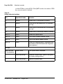
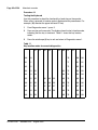
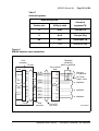
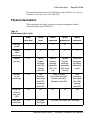
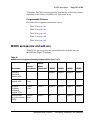
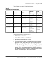
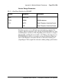
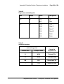
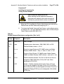
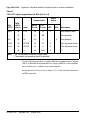
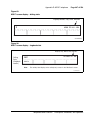
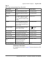
The first four status messages appear as MN, MJ, C/H, and CW on line 4 of
the display screen panel. BUSY and NIGHT are combined with the status of
the Release lamp to indicate the console status as shown in Table 4.
Table 4
Release lamp indicator status
Type
Indicator
Status
Night
Busy
Release
Display screen status (line 4)
ON
X
X
NIGHT
OFF
ON
X
BUSY
OFF
OFF
ON
IDLE
OFF
OFF
OFF
ACTIVE
X
X
X
EMERGENCY
Telephones and Consoles
Description, Installation, and Operation
Page 56 of 504
Attendant consoles
If the emergency power fail transfer feature is activated, the console status
will be displayed as EMERGENCY.
Connections
The line cord connects to the rear of the M2250 attendant console through a
25-pin subminiature D-type connector. The jack connector is attached to the
line cord for user safety and equipment protection (pins are not exposed).
Having the plug connector mounted in the console also prevents interchanges
between the line cord and the serial data port connectors (the serial data port
in the console has a jack connector).
Identical two-prong G3 type connectors are provided on each side of the
console body to permit handset or headset connection at either side of the
console. The M2250 attendant console is compatible with both carbon and
electret handsets or headsets. The electret handset plug is
orientation-dependent and is labeled accordingly.
The attendant console is connected to the system through two digital ports –
one port for Call Service processing and one for Call Destination
processing – with three additional ports for powering, for a total of five ports.
The PCCIU interface used for the PC-based Console software application
requires only three ports in total.
The attendant console requires a Digital Line Card (DLC) or an Integrated
Services Digital Line Card (ISDLC) NT8D02 or later.
Local console controls
Visual contrast on the display panel can be adjusted using the Contrast option
on the Options menu.
From the Options menu, four-line mode can be changed to two-line mode for
easier viewing and to use larger fonts.
The pitch and volume of the buzz tone on the console can be adjusted by
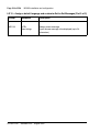
the user.
Any one of 15 languages can be chosen for the console screen displays:
English, French, Spanish, German, Italian, Norwegian, Irish (Gaeilge),
553-3001-367
Standard 3.00
August 2005
Attendant consoles
Page 57 of 504
Turkish, Katakana, P.R.C. (People’s Republic of China), Taiwan, Korean,
Polish, Czech/Slovak, or Hungarian.
When the languages P.R.C., Taiwanese, and Korean are chosen, the attendant
console uses two-line display.
The attendant console is equipped with a real-time clock/calendar. The time
of day (hours, minutes, and seconds) and the date (day, month, and year) are
displayed on line 1 of the display screen.
The sound of key clicks can be turned on or off. The pitch and volume of key
clicks can be adjusted.
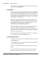
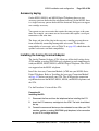
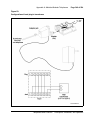
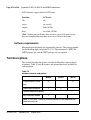
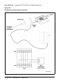
Wiring
The M2250 attendant console requires a 16-pair cable terminated on an
Amphenol connector.
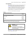
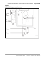
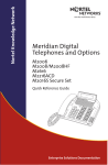
When zone cabling and conduit are used, assign a block of numbers or letters
to each zone. Allow for growth when assigning blocks of numbers.
Cable markers are normally an adhesive-backed cloth tape 1/2 inches wide by
3-1/2 inches long (15 mm by 65 mm) with preprinted numbers.
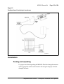
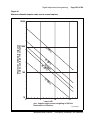
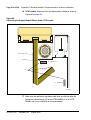
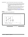
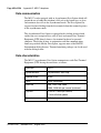
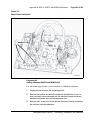
For limits and cabling for analog (500/2500-type) telephones, refer to
Figure 12 on page 58.
For a list of terminal connections, see Table 5 on page 59.
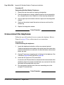
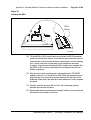
Installing wiring
Follow the steps in Procedure 5 to install the wiring for a telephone.
Procedure 5
Installing wiring
1
Assign a number to the wire or cable used.
2
Attach the assigned number to the wire or cable at the end nearest the
telephone, using a cable marker.
Telephones and Consoles
Description, Installation, and Operation
Page 58 of 504
Attendant consoles
3
Run the wire or cable between the telephone location and nearest
cross-connect point (if not previously run).
4
Connect the cable or wire to the telephone connecting block.
5
Designate the telephone connecting block.
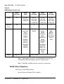
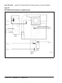
Figure 12
Zone cabling and conduit assignment
Zone
Zone
Zone
2.1
Zone
2.2
2
1.2
4
3
1
1.1
6
5
Zone Conduit
Each Zone is
approximately
600-800 feet
8
7
Apparatus
Closet
11
12
10
9
13
14
Satellite
Closet
18
15
19
16
20
17
553-AAA0579
6
553-3001-367
Cross-connect the pairs at intermediate cross-connect points (if required)
and terminate at the cross-connect terminal.
Standard 3.00
August 2005
Attendant consoles
7
Page 59 of 504
Terminate leads at the cross-connect terminal and designate the blocks
according to the house cable plan.
Table 5
Terminal connections
Connecting block
Designations
Inside wiring
Colors
NE-47QA or
QBB1B
NE-284-74-500
1 adapter
NE-625F
TELADAPT
plugs and jacks
Z station wire
16/25-pair cable
G
1T
T1 (G)
G
W-BL
R
1R
R1 (R)
R
BL-W
BK
X1
AUX (BK)
BK
W-O
Y
X2
GND (Y)
Y
O-W
5
R
T2 (BL)
W-SL
6
B
R2 (W)
SL-W
Normal operating ranges
The M2250 attendant console has a maximum permissible loop length of
3500 ft (915 m), assuming 24 AWG (0.5 mm) wire with no bridge taps. A
15.5 dB loss at 256 kHz defines the loop length limit.
Installation
This section provides installation instructions for the M2250 attendant
console. For Attendant PC Software installation instructions, refer to
Meridian 1 Attendant PC: Software Installation Guide.
Packing and unpacking
Use proper care while unpacking the M2250 attendant console. Check for
damaged containers so that appropriate claims can be made to the transport
company for items damaged in transit.
Telephones and Consoles
Description, Installation, and Operation
Page 60 of 504
Attendant consoles
If an attendant console must be returned to the factory, pack it in the
appropriate container to avoid damage during transit. Remember to include
all loose parts (cords, handset, power unit, labels, and lenses) in the shipment.
Installation and removal
Use the following procedures to install and remove M2250 attendant
consoles.
Note: Although M2250 attendant consoles do not require a static
discharge ground connection, the connection should be installed to
protect any earlier vintage attendant consoles that may be used as
replacements.
Choose a clean, level work surface and place several sheets of soft, clean
paper between the attendant console and the work surface. This will prevent
scratching or otherwise damaging the top cover, LCD indicators and screen,
and the feature keys of the attendant console.
Installing the M2250 attendant console
Follow the steps in Procedure 6 to install the M2250 attendant console.
Procedure 6
Installing the M2250 attendant console
553-3001-367
1
Ensure that a 16-pair or 25-pair cable equipped with a 25-pair Amphenol
connector is installed at the attendant console’s location.
2
Unpack and inspect the attendant console for damage. If the console is
damaged, notify the supplier.
3
Designate the console according to the features provided.
4
Connect the Amphenol plug on the attendant console to the Amphenol
jack coming from the Main Distribution Frame (MDF).
a.
Fasten the Amphenol connectors together and secure the captive
screws on the cable.
b.
Ensure that the connectors are secured in a connector mounting, if
provided, or to the wall. Do not leave connectors unprotected on the
floor.
Standard 3.00
August 2005
Attendant consoles
Page 61 of 504
5
Add a line circuit for the attendant console, if not already done. Refer to
Circuit Card: Description and Installation (553-3001-211).
6
Cross-connect the attendant console at the cross-connect terminal. See
Procedure 12 on page 69.
7
Enter the related attendant console data in the system. Refer to Software
Input/Output: Administration (553-3001-311).
8
Test the console features using the attendant console user guide.
Note: Refer to Circuit Card: Description and Installation (553-3001-211)
for circuit card installation procedures.
End of Procedure
Removing the M2250 attendant console
Follow the steps in Procedure 7 if it is necessary to remove an M2250
attendant console.
Procedure 7
Removing the M2250 attendant console
1
Remove related attendant console data from the system memory. Refer
to the Software Input/Output: Administration (553-3001-311).
2
Locate and remove cross-connections from the attendant console cable
at the cross-connect terminal. See Procedure 12 on page 69.
3
Remove the circuit card if required. Refer to Circuit Card: Description and
Installation (553-3001-211).
Note: Do not remove the circuit card if any of the remaining units on the
card are assigned.
4
Disconnect the Amphenol connector on the end of the cable leading to the
cross-connect terminal from the connector on the cable leading to the
attendant console.
5
Pack the attendant console, handset, and cords in a suitable container.
End of Procedure
Telephones and Consoles
Description, Installation, and Operation
Page 62 of 504
Attendant consoles
Removing the M2250 attendant console top cover
Follow the steps in Procedure 8 to remove the M2250 Attendant top cover.
Procedure 8
Removing the M2250 attendant console top cover
1
Disconnect any plugs and cords from the attendant console.
2
Remove the ten 10-mm fastening screws in the flange of the attendant
console, as well as one 10-mm and one 40-mm screw on the base of the
attendant console. See Figure 13 for the M2250 assembly drawing.
Figure 13
M2250 assembly drawing (exploded view)
Support screw
(1 of 10)
LCD screen
LCD screen
hinge assembly
Base housing
assembly
Ribbon cable
553-AAA0580
Faceplate
assembly
553-3001-367
Standard 3.00
August 2005
Attendant consoles
Page 63 of 504
3
Holding the top cover and the base together by hand, turn the attendant
console right-side up and place it back on the work surface.
4
Carefully lift the faceplate straight up and disconnect the 20-pin plug
ribbon cable located at J2.
Note: On attendant consoles with a display attached to the top cover, do
not connect or disconnect the cable to the display unless the attendant
console line cord is disconnected.
End of Procedure
Installing the M2250 attendant console top cover
Follow the steps in Procedure 9 to install the M2250 attendant console top
cover.
Procedure 9
Installing the M2250 attendant console top cover
1
Set the QMT2 dip switch. To locate the dip switch, look at the attendant
console from the top. The QMT2 dip switch is the only dip switch on the
topmost circuit board. Set the switch to ON (enable QMT2) or OFF
(disable QMT2).
Note: The QMT2 feature must be enabled in system software. Refer to
LD 12 in Software Input/Output: Administration (553-3001-311).
2
Carefully lift the top cover straight up and connect the 20-pin plug ribbon
cable to J2.
3
Put the top cover back on the attendant console:
4
a.
Place the top cover onto the base housing, and turn the attendant
console upside down.
b.
Reinsert and tighten the ten 10-mm fastening screws on the flange.
c.
Reinsert and tighten one 10-mm and one 40-mm fastening screw on
the back.
Return the attendant console to its working position, reconnect the plugs
and cords, and test the features.
End of Procedure
Telephones and Consoles
Description, Installation, and Operation
Page 64 of 504
Attendant consoles
Performing a loopback test
Follow the steps in Procedure 10 to perform a loopback test on the M2250
attendant console.
Procedure 10
Performing a loopback test on the
M2250 attendant console
1
Make a loopback connector. Prepare a blank 25-way RS-232 plug by
internally connecting pins 2 and 3 together with strapping wire.
2
Press the Shift key to access Level 1 mode.
3
Press the F4 (function) key to access the Diagnostics menu on the LCD
screen.
4
Plug the loopback connector into the Data Port RS-232 jack in the back
of the console.
5
Select the Data Port option from the Diagnostics menu by dialing 3. The
LCD screen displays OK when the test is successfully completed.
If there is a hardware fault on the M2250, A0H is displayed.
If the blank RS-232 connector is not plugged into the data port correctly
(as described in Step 4), the display reads 90H or A0H.
6
Press the asterisk (*) key to repeat the test.
7
To exit the test mode press the octothorpe (#). to return to the main
Diagnostics menu.
8
Press the octothorpe (#) to return to normal operating mode.
9
Remove the loopback connector from the Data Port RS-232 jack.
End of Procedure
Designating keys on the M2250 attendant console
Refer to the work order to determine the features and key designations for
each attendant console. Designate each key on the attendant console by
placing its feature name (from the designation sheet) in the key cap that fits
on the key.
553-3001-367
Standard 3.00
August 2005
Attendant consoles
Page 65 of 504
The Directory Number (DN) designation window on the attendant console is
located above the keypad.
Follow the steps in Procedure 11 to designate keys on an M2250 attendant
console.
Procedure 11
Designating keys on an M2250 attendant console
1
Remove the cap from each key requiring a designation by gently pulling
upward on the cap.
2
Remove the appropriate designation from the sheet of designations.
3
Place the designation in the cap, place the cap over the corresponding
key, and gently press down. Repeat this procedure for all keys requiring
a designation.
4
Insert a paper clip in the hole at the left or right end of the DN designation
window. Pry the window open.
5
Insert the number tag, and replace the designation window.
End of Procedure
The following figures show the typical key designations for the M2250
attendant console:
•
Figure 14 on page 66 shows the key designations for the M2250
attendant console in Shift mode.
•
Figure 15 on page 67 and Figure 16 on page 68 show the M2250
attendant console in Unshift mode.
Telephones and Consoles
Description, Installation, and Operation
Page 66 of 504
Attendant consoles
Figure 14
M2250 key designations in Shift mode (QMT2 not enabled)
BLF Functions only
Note
ICI9
ICI8
CAS
BSY
C/H
OMN
VDH
VUP
DMN
F1
F2
F3
F4
CGM
MODE
SS
SD
FEAT9
FEAT8
TGB7
ICI7
FEAT7
TGB6
ICI6
LPK5
EX SR
FEAT6
TGB5
ICI5
LPK4
EX DS
FEAT5
TGB4
ICI4
LPK3
RL SR
FEAT4
TGB3
ICI3
LPK2
1
2
3
4
5
6
RL DS
FEAT3
8
9
BLF
FEAT2
0
#
SHIFT
FEAT1
HOLD
FEAT0
TGB2
ICI2
LPK1
7
TGB1
ICI1
LPK0
*
TGB0
ICI0
RLS
553-AAA0581
553-3001-367
Standard 3.00
August 2005
Attendant consoles
Page 67 of 504
Figure 15
M2250 key designations in Unshift mode (QMT2 enabled)
ICI09
ICI19
CAS
BSY
C/H
OMN
VDH
VUP
DMN
F1
F2
F3
F4
SS
SD
FEAT9
ICI08
ICI18
FEAT8
ICI07
ICI17
ICI06
ICI16
LPK5
EX SR
FEAT6
ICI05
ICI15
LPK4
EX DS
FEAT5
ICI04
ICI14
LPK3
RL SR
FEAT4
ICI03
ICI13
LPK2
RL DS
FEAT3
ICI02
ICI12
ICI01
ICI00
FEAT7
1
2
3
4
5
6
LPK1
7
8
9
CONF 6
FEAT2
ICI11
LPK0
*
0
#
SHIFT
FEAT1
ICI10
RLS
HOLD
FEAT0
553-AAA0583
Telephones and Consoles
Description, Installation, and Operation
Page 68 of 504
Attendant consoles
Figure 16
M2250 designations in Unshift mode (QMT2 not enabled)
LCD Display
Screen
(4 or 2 lines
for M2250)
Scrolling
FEAT9
ICI9
ICI8
CAS BSY
F1
C/H
SS
F2
F3
SD
FEAT8
F4
FEAT7
ICI7
ICI6
LPK5
EX SR
FEAT6
ICI5
LPK4
EX DS
FEAT5
ICI4
LPK3
RL SR
FEAT4
ICI3
1
2
3
LPK2
4
5
6
RL DS
FEAT3
ICI2
LPK1
7
8
9
CONF6
FEAT2
ICI1
LPK0
*
0
#
SHIFT
FEAT1
ICI0
RLS
HOLD
FEAT0
553-AAA0584
Cross-connecting attendant consoles
Terminations are located on the vertical side of the distributing frame when
frame-mounted blocks are used and located in the blue field when
wall-mounted blocks are used.
Line circuit card (TN) terminations are located on the horizontal side of the
distributing frame when frame-mounted blocks are used and located in the
white field and wall-mounted blocks are used.
Follow the steps in Procedure 12 on page 69 to cross-connect attendant
consoles.
553-3001-367
Standard 3.00
August 2005
Attendant consoles
Page 69 of 504
Procedure 12
Cross-connecting attendant consoles
1
Locate the attendant console terminations at the cross-connect terminal.
2
Connect Z-type cross-connecting wire to the leads of the attendant
console.
3
Locate the line circuit card (TN) terminations.
4
Run and connect the other end of the cross-connecting wire to the
assigned TN terminal block.
End of Procedure
Refer to Table 6 for details on Z-type cross-connecting wire and Table 7 on
page 70 for a list of inside wiring colors.
Table 6
Z-type cross-connecting wire
Size
Gauge
Color
Designation
1 pr
24
Y-BL
Tip
BL-Y
Ring
W-BL
Voice T
BL-W
Voice R
W-O
Signal T
O-W
Signal R
W-G
Power
G-W
Power
3 pr
24
Telephones and Consoles
Description, Installation, and Operation
Page 70 of 504
Attendant consoles
Table 7
Inside wiring colors
553-3001-367
Z station wire
16/25-pair cable
Connect to
equipment TN
G
W-BL
First pair Tip
R
BL-W
First pair Ring
BK
W-O
Second pair Tip
Y
O-W
Second pair Ring
Standard 3.00
August 2005
Attendant consoles
Page 71 of 504
Figure 17
M2250 attendant console cross-connections
Cross connect
block
W-BL
BL-W
To 1st TN
26
1
TCM Primary
W-OR
OR-W
To 2nd TN
27
2
TCM Secondary
W-SL
SL-W
30
5
•
R-OR
OR-R
•
R-G
G-R
32
7
33
8
BK-BL
BL-BK
36
11
BK-BR
BR-BK
39
14
+ VPS
Y-BL
BL-Y
41
16
VPS RTN
Y-OR
OR-Y
42
17
To 3rd TN
ASM
To 4th TN Tip
Note 1
To 4th TN Ring
To 5th TN Tip
+AUX
•
•
To 5th TN Ring
Part of Power Fail
or Energy Transfer
Major Alarm
GND
TC
GND
ALARM
–AUX
M2250 Console
(console connector)
Note 2
25 pair cable from console to MDF
Code Blue
Relay 2
Relay 1
V-SL
SL-V
50
25
553-AAA0585
Telephones and Consoles
Description, Installation, and Operation
Page 72 of 504
Attendant consoles
The following notes refer to Figure 17 on page 71, which illustrates the
M2250 attendant console cross-connections.
Note 1: The M2250 is powered by means of the line circuits. In addition
to the primary TN, secondary TN, and ASM TN, two TNs are cabled to
the M2250 using the +AUX and –AUX leads. The maximum loop length
is 3000 ft of 24 AWG wire.
Note 2: When additional options are used (BLF or display backlight
option), an additional 16 V DC power supply is required. The 16 V DC
source is cabled using +VPS and VPS RTN leads. The maximum
distance from the console to the power source is 120 feet of 24 AWG
wire. Please note: if both options are installed, only one 16 V DC power
supply is required.
Note 3: Nortel recommends that five consecutive TNs on the line circuit
be allocated for each console.
Note 4: When used with the ISDLC, the M2250 requires NT8D02 or
later.
Note 5: The third TN must be cross-connected to the console cable
WH/SL pair whether or not an ASM (Attendant Supervisory Module) is
installed. This third TN provides additional console power which is
required.
Table 8 on page 73 explains where each M2250 cable pair is connected.
Table 9 on page 75 lists the M2250 typical cross-connections.
553-3001-367
Standard 3.00
August 2005
Attendant consoles
Page 73 of 504
Table 8
M2250 attendant console connections (Part 1 of 3)
Mounting cord
16/25-pair connector cable
Lead
designation
Pin
number
Pair
number
Color
Connected to
TCM primary
26
1T
W-BL
TN #1
1
R
BL-W
27
2T
W-O
2
R
O-W
Attendant
Supervisory
Module
30
5T
W-SL
5
R
SL-W
Spare
31
6T
R-BL
6
R
BL-R
32
7T
R-O
7
R
O-R
33
8T
R-G
8
R
G-R
34
9T
R-BR
9
R
BR-R
TCM secondary
+AUX
–AUX
Spare
Telephones and Consoles
TN #2
TN #3
TN #4
TN #5
Description, Installation, and Operation
Page 74 of 504
Attendant consoles
Table 8
M2250 attendant console connections (Part 2 of 3)
Mounting cord
16/25-pair connector cable
Lead
designation
Pin
number
Pair
number
Color
Spare
35
10T
R-SL
10
R
SL-R
Power Fail or
36
11T
BK-BL
GND (Note 1)
Energy Transfer
11
R
BL-BK
TC (Note 2)
Spare
37
12T
BK-O
Spare
12
R
O-BK
Spare
38
13T
BK-G
Spare
13
R
G-BK
GND
39
14T
BK-BR
GND (Note 1)
Major Alarm
14
R
BR-BK
ALM (Note 2)
Spare
40
15T
BK-SL
15
R
SL-BK
41
16T
Y-BL
16
R
BL-Y
42
17T
Y-O
17
R
O-Y
50
25T
Y-SL
Relay 2
25
R
SL-Y
Relay 1
VPS
VPS RTN
Connected to
Spare
Code Blue
553-3001-367
Standard 3.00
August 2005
Attendant consoles
Page 75 of 504
Table 8
M2250 attendant console connections (Part 3 of 3)
Mounting cord
Lead
designation
16/25-pair connector cable
Pin
number
Pair
number
Color
Connected to
Note 1: Connect to Pin 3 or 28 of the appropriate PFJ5 terminal block.
Note 2: Connect TC to Pin 29 or 5 and ALM to Pin 4 or 31 of the
appropriate PFJ5 terminal block.
Table 9
M2250 typical cross-connections (Part 1 of 2)
Pair
Pins
Pair
Color
DLC
Connections
ISDLC
Connections
1T
26
W-BL
Unit
Unit
1R
1
BL-W
0
0
2T
27
W-O
Unit
Unit
2R
2
O-W
1
8
3T
28
W-G
Unit
Unit
3R
3
G-W
2
1
4T
29
W-BR
Unit
Unit
4R
4
BR-W
3
9
5T
30
W-S
Unit
Unit
5R
5
S-W
4
2
6T
31
R-BL
Unit
Unit
6R
6
BL-R
5
10
7T
32
R-O
Unit
Unit
7R
7
O-R
6
3
Telephones and Consoles
Description, Installation, and Operation
Page 76 of 504
Attendant consoles
Table 9
M2250 typical cross-connections (Part 2 of 2)
553-3001-367
Pair
Pins
Pair
Color
DLC
Connections
ISDLC
Connections
8T
33
R-G
Unit
Unit
8R
8
G-R
7
11
9T
34
R-BR
Unit
Unit
9R
9
BR-R
8
4
10T
35
R-S
Unit
Unit
10R
10
S-R
9
12
11T
36
BK-BL
Unit
Unit
11R
11
BL-BK
10
5
12T
37
BK-O
Unit
Unit
12R
12
O-BK
11
13
13T
38
BK-G
Unit
Unit
13R
13
G-BK
12
6
14T
39
BK-BR
Unit
Unit
14R
14
BR-BK
13
14
15T
40
BK-S
Unit
Unit
15R
15
S-BK
14
7
16T
41
Y-BL
Unit
Unit
16R
16
BL-Y
15
15
Standard 3.00
August 2005
Attendant consoles
Page 77 of 504
Operation
This section contains operating procedures for the M2250 attendant console.
The attendant console faceplate layout is shown in Figures 14 through 16,
starting on page 66. Refer to these figures as the basis for component location
references throughout this section.
M2250 configurations
The M2250 attendant console can be configured to operate with the QMT2
feature, which is provided by a QMT2 add-on module incorporated in the
console. Instead of having to add a keystrip unit, the technician can set a dip
switch on the keyboard/controller Printed Circuit Panel (PCP) to ON (enable
QMT2) or OFF (disable QMT2). It is important that the system software
configuration and the QMT2 dip switch be set correctly.
For more information, refer to the section on LD15 in the following
documents:
•
Features and Services (553-3001-306)
•
Software Input/Output: Administration (553-3001-311)
QMT2 feature disabled
When the QMT2 feature is disabled, the following conditions apply:
•
If the console is not in Shift mode, keystrip AK is inactive.
•
If the console is in Shift mode, the keys in strip AK function as Trunk
Group Busy (TGB) keys, if configured in the system software.
•
If the operator presses any of these keys, the associated trunk group is
busied out.
•
The triangle points aimed to the left of keystrip AK are never active.
•
If the operator presses any key outside keystrip AK when the console is
in Shift mode, the console performs the function associated with that key.
The Shift indicator remains on.
•
The keys in keystrip BK function as Incoming Call Identification
(ICI) keys.
Telephones and Consoles
Description, Installation, and Operation
Page 78 of 504
Attendant consoles
QMT2 feature enabled
When the QMT2 feature is enabled, the following conditions apply:
•
If the console is not in Shift mode, the keys in strip AK and/or BK
function as Incoming Call Identification (ICI) keys.
•
If the console is in Shift mode, the keys in keystrips AK and BK function
as Trunk Group Busy (TGB) keys. That is, they imitate the keystrips of
the QMT2 add-on module as follows:
— The LCD indicators pointing to the left indicate busy trunks.
— The LCD indicators pointing to the right indicate incoming calls.
Attendant PC requirements
To install the PC-based Console software application, a PC-compatible
Pentium system is required, with the following:
•
minimum 16 MB RAM
•
hard disk with at least 10 MB free disk space
•
17-inch SVGA color monitor
•
16 bit sound board
•
Network interface adapter
•
RS232 serial port
For complete installation and operation instructions, refer to the
Attendant PC: Description, Installation, and Operation (553-3001-320).
553-3001-367
Standard 3.00
August 2005
Attendant consoles
Page 79 of 504
Figure 18
PC Console Interface Unit
brandline
insert
headset/handset
volume control
Status LED
alerter speaker
553-AAA0576
M2250 feature key modes
Functions shown for some of the feature keys in Table 3 page 51 vary
depending on which console mode is in effect while the key is being pressed.
Table 10 on page 80 lists the various alternate feature key functions.
When a feature key is pressed while the attendant console is in a mode other
than normal or Level 1, nothing happens.
When in the normal call processing mode, access the Level 1 mode by
pressing the Shift key. The LCD indicator beside the shift key lights and
remains on throughout all options and menus. It goes out only upon return to
normal call processing. All call processing keys that do not have a dual
function perform normally while the console is in Level 1 mode. Press the
Shift key again to return to normal call processing.
On the M2250 attendant console, press the pound (#) key to exit from any
submenu from the Options menu, or from the Diagnostics menu to normal
operating mode. Press the Shift key to return to the Level 1 mode.
Level 1 mode also provides access to additional call processing features, as
well as to options and maintenance features. One of the additional call
processing features is access to Trunk Group Busy (TGB) keys that are
locked out in normal mode. For example, in normal mode, there are ten
Telephones and Consoles
Description, Installation, and Operation
Page 80 of 504
Attendant consoles
available TGB keys on the M2250. With QMT2 enabled, the number of TGB
keys on each console is doubled.
Table 10
Softkey alternate functions
Key
Operational mode
Function
F1
Normal
Selects line 2 of the display for scrolling.
F2
Normal
Scrolls left on the selected line, at 8 characters
per step.
F3
Normal
Scrolls right on the selected line, at 8 characters
per step.
F4
Normal
Selects line 3 of the display screen for scrolling.
Shift, F1
Level 1
Selects the Options menu.
Shift, F2
Level 1
Turns down the alerter speaker volume.
Shift, F3
Level 1
Turns up the alerter speaker volume.
Shift, F4
Level 1
Selects the Diagnostic menu. (A password must
be entered on the M2250 before the Diagnostics
menu appears.)
Options menu
The Options menu is displayed.
Press dial pad key 1
Accesses Contrast menu. (Refer to user guide
for contrast setting routines.)
Press dial pad key #
Returns to Options menu.
Example:
Press Shift and
F1 (in sequence)
553-3001-367
Standard 3.00
August 2005
Attendant consoles
Page 81 of 504
M2250 console diagnostics
Use the Diagnostics menu to check the functions of the console and to
perform tests. To enter the Diagnostics mode, use Procedure 13. Figure 19
shows the main Diagnostics menu for the M2250 attendant console.
Procedure 13
Entering the M2250 Diagnostics mode
1
Press the Shift key.
2
Press the
3
On M2250 consoles, enter the password 9999.
4
Press the asterisk (*) key to enter Diagnostics menu 1. To toggle between
menu 1 and menu 2, press the asterisk (*) key.
5
To quit the Diagnostics mode, press the octothorpe (#) key.
key (F4 function key).
End of Procedure
Follow the procedures listed below to perform the Diagnostic tests.
Figure 19
Console Diagnostics menus
DIAGNOSTICS MENU:
1. KEYBOARD
4. ICs
{1}
2. LAMPS
5. LAMP FIELD
*
<next>
3. DATA PORT
6. ALERTER
# <exit>
DIAGNOSTICS MENU:
1. DISPLAY
4. CONTROL
{2}
2. FIRMWARE
5. RESET
*
<next>
3. QMT2
# <exit>
553-AAA0577
Telephones and Consoles
Description, Installation, and Operation
Page 82 of 504
Attendant consoles
Procedure 14
Testing the Keyboard
Use this procedure to check the functionality of each key on the console.
When a key is pressed, its location code is displayed within parentheses. For
example, (00) denotes the upper left-hand ICI key.
1
From Diagnostics menu 1, press 1.
2
Press any key on the console. The display shows the key’s location code,
indicating that the key is functional. Table 11 shows the key location
codes.
3
Press the octothorpe (#) key to exit and return to Diagnostics menu 1.
Table 11
Key location codes for console diagnostics
22
553-3001-367
21
20
34
54
60
61
62
00
10
70
80
90
01
11
71
81
91
02
12
72
82
92
03
13
23
63
73
83
93
04
14
24
64
74
84
94
05
15
25
35
45
55
65
75
85
95
06
16
26
36
46
56
66
76
86
96
07
17
27
37
47
57
67
77
87
97
08
18
28
38
48
58
68
78
88
98
09
19
29
69
79
89
99
Standard 3.00
August 2005
Attendant consoles
Page 83 of 504
Procedure 15
Testing the LCD indicators
Use this procedure to check the functionality of each LCD indicator on the
console.
1
From the Diagnostics menu 1, press 2.
2
Press 1 to turn all lamps ON. Press the asterisk (*) to turn each lamp OFF
one by one.
3
Press 2 to turn all lamps OFF. Press the asterisk (*) to turn each lamp ON
one by one.
4
Press the octothorpe (#) to exit and return to Diagnostics menu 1.
End of Procedure
Procedure 16
Testing the data port
Use this procedure to perform a loopback test on the RS-232 port at the back
of the console. Before performing the test, a connector (25-way D-plug) with
pin 2 shorted to pin 3 should be inserted in RS-232 port. A failure code is
displayed if any error is found.
1
From Diagnostics menu 1, press 3. The display shows OK if the test is
successful.
2
Press the asterisk (*) to repeat the loopback test.
3
Press the octothorpe (#) to exit and return to Diagnostics menu 1.
End of Procedure
Procedure 17
Testing the ICS
Use this procedure to check the functionality of any peripheral devices
connected to the User Interface Printed (UIP)and the Audio System Interface
Printed (ASIP) microprocessor circuit cards within the console. A failure code
is displayed if any error is found.
1
From Diagnostics menu 1, press 4.
2
Press the asterisk (*) to perform the ICS test.
Telephones and Consoles
Description, Installation, and Operation
Page 84 of 504
Attendant consoles
3
Press the octothorpe (#) to exit and return to Diagnostics menu 1.
End of Procedure
Procedure 18
Testing the Busy Lamp Field/Console
Graphics Module
Use this procedure to check the functionality of the BLF/CGM. Once in this
menu, the dial pad is in CGM mode. When any dial pad keys are pressed,
except the octothorpe (#) key, the keys are echoed on the BLF/CGM.
1
From Diagnostics menu 1, press 5.
2
Press keys from 0 – 9 and the asterisk (*) on the dial pad. Check the CGM
to see that they are echoed.
3
Press the octothorpe (#) to exit and return to Diagnostics menu 1.
Note: For more information on installation and operation of this feature,
see “Busy Lamp Field/Console Graphics Module” on page 32, or refer to
the Busy Lamp Field/Console Graphics Module User Guide.
End of Procedure
Procedure 19
Checking the Alerter
Use this procedure to check the pitches and volume levels of the alerter and
auxiliary tone channel.
1
From Diagnostics menu 1, press 6.
2
Follow these instructions in any order:
Press key 1 to turn the buzz and auxiliary tones ON.
Press key 2 to turn the buzz and auxiliary tones OFF.
Press key 3 to increase the pitch of the buzz and auxiliary tones.
Press key 4 to decrease the pitch of the buzz and auxiliary tones.
Press key 5 to increase the volume of the buzz and auxiliary tones.
Press key 6 to decrease the volume of the buzz and auxiliary tones.
3
Press the octothorpe (#) to exit and return to Diagnostics menu 1.
End of Procedure
553-3001-367
Standard 3.00
August 2005
Attendant consoles
Page 85 of 504
Procedure 20
Testing the Display
Use this procedure to check the functionality of the alphanumeric display
panel. Cycle through a number of different display patterns to check for visual
defects.
1
From Diagnostics menu 2, press 1.
2
Press the asterisk (*) to change the display screen pattern. Continue
changing the pattern until all the patterns have been cycled through.
3
Press the octothorpe (#) to exit and return to Diagnostics menu 1.
End of Procedure
Procedure 21
Displaying the firmware version numbers
Use this procedure to display the release and issue numbers of the firmware
installed on the UIP and ASIP microprocessor circuit cards.
1
From Diagnostics menu 2, press 2. The display shows the firmware
release and issue numbers, as shown below:
DIAGNOSTICS:
2
FIRMWARE
ASIP: XX XX
UIP: XX XX
Press the octothorpe (#) to exit and return to Diagnostics menu 1.
End of Procedure
Procedure 22
Displaying and resetting the QMT2 switch status
Use this procedure to display the current state of the QMT2 dip switch inside
the console and to change the setting for verification testing (LD 31). After a
change, the actual switch setting will return to its original state after a time-out
period of about three minutes.
1
From Diagnostics menu 2, press 3.
2
Press the asterisk (*) to toggle between QMT2 ON and OFF.
Telephones and Consoles
Description, Installation, and Operation
Page 86 of 504
Attendant consoles
3
Press the octothorpe (#) to exit and return to Diagnostics menu 1.
End of Procedure
Procedure 23
Toggling control gates
Use this procedure to turn the conference bridge analog control gates, the
auxiliary tone channel, and the Code Blue Relay ON or OFF. Note that the
auxiliary control only affects the control gate on the ASIP circuit card. To
actually generate a tone, use the Alerter menu.
1
From Diagnostics menu 2, press “4.”
DIAGNOSTICS: CONTROL
1. SCR
2. DST
3. ARX
{0}
{0}
{0}
* <OFF>
2
4. ATX
{0}
5. TON
6. REL
{0}
{0}
# <exit>
Follow the appropriate instruction below:
Press key 1 to toggle the primary control gate between ON and OFF.
Press key 2 to toggle the secondary control gate between ON and OFF.
Press key 3 to toggle the attendant receive control between ON and OFF.
Press key 4 to toggle the attendant transmit control between ON and
OFF.
Press key 5 to toggle the auxiliary tone control between ON and OFF.
Press key 6 to toggle the relay control between ON and OFF.
3
Press the asterisk (*) to turn all the control gates OFF.
4
Press the octothorpe (#) to exit and return to Diagnostics menu 1.
End of Procedure
553-3001-367
Standard 3.00
August 2005
Attendant consoles
Page 87 of 504
Reset
To perform a hard reset of the console, from Diagnostics menu 2, press 5. The
reset is performed immediately. All devices and memory on the UIP and
ASIP boards are reset as if the power cord were unplugged and plugged in
again.
M2250 failure codes
A failure code appears on the display in response to the detection of a
hardware fault.
Refer to Table 12 for an explanation of failure codes and possible solutions.
Table 12
M2250 failure codes (Part 1 of 2)
Failure
code
Printed
circuit
pack (PCP)
40H
UIP
Reason
What to do
The PSG, U13, is not
responding.
Unplug the line cord and plug it in
again. If the failure code still appears,
there is an electrical fault in the
console, and it should be returned.
Note: Log the failure code with the
returned unit, as it gives an indication
of which component has failed.
20H
UIP
The RTC, U16, is faulty.
Same as for 40H.
10H
UIP
The RAM IC, U1, is faulty.
Same as for 40H.
08H
UIP
A key in column A is stuck.
Unplug the line cord.
Free the key if it is stuck.
Plug in the line cord.
If the failure code still appears, the
console is faulty and should be
returned.
09H
UIP
A key in column B is stuck.
Same as for 08H.
Telephones and Consoles
Description, Installation, and Operation
Page 88 of 504
Attendant consoles
Table 12
M2250 failure codes (Part 2 of 2)
Failure
code
Printed
circuit
pack (PCP)
Reason
What to do
0AH
UIP
A key in column C is stuck.
Same as for 08H.
0BH
UIP
A key in column D0 is
stuck.
Same as for 08H.
0CH
UIP
A key in column D1 is
stuck.
Same as for 08H.
0DH
UIP
A key in column D2 is
stuck.
Same as for 08H.
0EH
UIP
A key in column E is stuck.
Same as for 08H.
0FH
UIP
A key in column F is stuck.
Same as for 08H.
A0H
ASIP
The RS-232 has failed the
loopback test.
Check to see if the loopback
connector is inserted. If not, insert it
and perform the loopback test again.
If the failure code still appears, turn
the console off and on while the
connector is inserted.
Perform the loopback test again. If the
failure code still appears, the console
is faulty and should be returned.
90H
ASIP
ASM A44#3, U1, is faulty.
Same as for 40H.
88H
ASIP
Secondary A44#2, U2, is
faulty.
Same as for 40H.
84H
ASIP
Primary A44#1, U1, is
faulty.
Same as for 40H.
82H
ASIP
The UART, U5, is faulty.
Same as for 40H.
81H
ASIP
The RAM, U8, is faulty.
Same as for 40H.
553-3001-367
Standard 3.00
August 2005
Attendant consoles
Page 89 of 504
The failure codes produced by the firmware in response to the detection of a
hardware fault are bit-significant as follows:
B7
B6
B5
B4
B3
B2
B1
B0
0
PSG
RTC
RAM
KEYS
c2*
c1*
c0*
1
ASIP
RS-232
A44#3
A44#2
A44#1
UART
RAM
* Refers to key’s column number.
Note: Bit 7 indicates whether the failure occurred on the user interface
printed circuit card (UIP) (B7=0) or on the audio and system interface
printed circuit card (ASIP) (B7=1).
In most instances, the failure code accurately identifies the faulty hardware
component. However, if the microprocessor is faulty, the readings may be
unreliable or misleading.
Failure code A0H is always shown if the loopback test has not been
performed. Refer to “Testing the data port” on page 83.
M2250 feature operation
Time and date
On the M2250, the time and date are automatically downloaded from the
system on power-up or console reset. The time and date are downloaded by
the switch whenever it runs a lamp audit. Only the visual format can be
changed.
Trunk Group Busy indicators
Trunk Group Busy (TGB) indicators show the status of each group of trunks.
If a TGB indicator is on steadily, the attendant has busied out all trunks in that
group by pressing the Shift key plus the TGB key. If a TGB indicator is
flashing, all the trunks in that group are actually busy.
In Supervisory mode, TGB indicators show the status of other consoles in the
customer group. If the indicator is off, the attendant position is in a Position
Telephones and Consoles
Description, Installation, and Operation
Page 90 of 504
Attendant consoles
Busy mode. When an indicator associated with a particular attendant is on,
the attendant is available to service calls.
Note: The M2250 attendant console must be equipped with the
Attendant Supervisory Module (NT7G10AA) to allow attendant
supervision.
Incoming Call Indicators
Incoming Call Indicators (ICI) display the various types of incoming calls
presented to the attendant console. They also indicate the number of calls and
the length of time calls have been queued.
•
If the indicator is on, one call has been queued for less than a certain
length of time (as defined by software).
•
If the indicator is flashing, one call has been queued for more than the
defined length of time, or there is more than one call in the queue.
Night service/busy
When the Shift key is off, press the Busy key to put the attendant console into
Position Busy mode. When the Shift key is on, press the Busy key to put the
console into Night Service mode. To return to normal operating mode, press
the Busy key again.
In a multi-console system, activating Night Service mode will busy out all
attendant consoles in the system.
Enhanced Night Service
This feature allows Public Network (Central Office [CO], Direct Inward Dial
[DID], Foreign Exchange [FEX], and Wide Area Telephone service [WAT])
trunks to be assigned to specific Directory Numbers (DN) during Night
Service.
With this feature each customer will be able to assign Public Network trunks
to one of nine Night Groups. Each Night Group will allow the customer to
define up to nine Night DNs. During Night Service incoming calls will be
routed to one of the Night DNs defined for the group. The actual DN the call
will be routed to is determined by the Night Service Option number selected
at that time.
553-3001-367
Standard 3.00
August 2005
Attendant consoles
Page 91 of 504
The customer will also be able to define whether Night Call Waiting tone will
be given to Night stations. With Night Call Waiting tone allowed, busy Night
stations are notified when an incoming call is terminating on them. The
incoming call will be queued on the Night station until it becomes idle. When
the Night station becomes idle, the incoming call will be presented.
This enhancement allows incoming DID trunks to be queued against busy
Night stations, thereby making the operation of the DID trunks the same as
for all other Public Network trunks.
Attendant Blocking of DN
The Attendant Blocking of DN (ABDN) feature enables the attendant to
block a DN for a telephone from receiving or making calls. This is
particularly useful when a caller dials the attendant DN and requests an
external (long distance) call. If the caller chooses to disconnect until the
attendant successfully places the call, the requesting DN becomes idle and
can receive or make calls. Therefore, the requesting DN could be busy when
the attendant establishes the requested call.
To prevent the requesting DN from being busy when the requested call is
completed, the attendant can block the DN from making or receiving calls. To
callers attempting to contact the blocked DN, the line appears busy. To a
caller attempting to use the blocked DN, the line is connected to the attendant.
When the attendant completes the external call, the attendant can call the
blocked DN and extend the call. This feature applies to both stand-alone and
ISDN network environments.
The Attendant Blocking of DN feature is available on the M2250 attendant
consoles. It is not valid on M2616 telephones used as attendant consoles.
Attendant and Network Wide Remote Call Forward
This modification to the Remote Call Forward feature (RCFW) allows a user
to program a call forward Directory Number from any attendant console or
station throughout the network. An RFW key on the attendant console allows
an attendant to view any station’s call forward status and to activate or
deactivate call forward for a station.
Telephones and Consoles
Description, Installation, and Operation
Page 92 of 504
Attendant consoles
Refer to ISDN Primary Rate Interface: Features (553-3001-369) for further
details.
Network Attendant Services
This feature allows attendant services to be distributed anywhere within a
Meridian ISDN network. If, at the time of an attendant request, attendant
services are not available at a station’s local node, connection to an attendant
at a remote node takes place. Call treatment is the same as for a connection to
a local attendant node.
Call processing
The attendant answers an incoming call by pressing the flashing loop key.
To answer a specific type of incoming call, press the ICI key next to the
appropriate ICI indicator. This removes the call from the queue and presents
it to the attendant.
ICI key assignments
An ICI key may be assigned more than one call type. Refer to Software Input/
Output: Administration (553-3001-311). If the Attendant Call Party Name
Display (ACPND) feature is equipped, all incoming calls are displayed by
calling party name or external call source. The following examples list
possible ICI key assignments:
553-3001-367
•
Attendant Intercept indicates that a call is being made by a station to a
facility to which that station is restricted, and the call has been routed to
the attendant console.
•
Listed Directory Numbers (maximum four) indicates that a call is
being made to an attendant console associated with one of the listed
directory numbers.
•
Dial 0 indicates that a station that is not fully restricted has dialed 0.
•
Fully Restricted Station indicates that a fully restricted station has
dialed 0.
•
Foreign Exchange indicates that the incoming call is from a foreign
exchange.
Standard 3.00
August 2005
Attendant consoles
Page 93 of 504
•
Wide Area Telephone Service indicates that the incoming call
originated at a wide area telephone exchange.
•
Recall indicates that a camped-on call or a call extended to an idle station
has not been answered for 30 seconds or that a station is recalling the
attendant.
•
Call Forward indicates that the call is being forwarded to the console
from a station within the system.
•
Tie Trunk indicates that the incoming call is on a tie trunk.
Operating keys
The operating key/lamp strips CI/CK, DI, EI, and FI/FK allow the attendant
to process calls from the console.
Key/lamp strips CI/CK and FI/FK have permanently assigned functions as
given in the following list.
•
Release allows the attendant to release a call presented to the console.
When the LCD associated with the RLS key is lit, it indicates that no
incoming calls are being presented to the console.
•
Loop Keys/Lamps allow the attendant to answer and originate calls
from the console. The first call in the incoming queue is automatically
presented to an idle loop key. Subsequent calls are queued and presented
to a loop key when a loop becomes idle. Call selection is made by
pressing the required ICI key. This action causes the call, which was
automatically presented to the loop key by the system, to be replaced by
the selected incoming call. In all cases, when the loop key is pressed, all
ICIs go dark except the one associated with the call presented to the
loop key.
•
Position Busy enables the attendant to put the console in Position Busy
mode. All calls directed to a console in Position Busy mode are
redirected to a free console in multiconsole installations or to the night
connection in single console installations. When a console is in Position
Busy mode, “BUSY” is shown on line 4 of the display.
Telephones and Consoles
Description, Installation, and Operation
Page 94 of 504
Attendant consoles
•
Night Service permits incoming calls to the attendant to be routed to a
preselected station. The Night Service key enables the attendant to assign
the Night Directory Number (DN) and to initiate Night Service. When
assigning the Night Service DN, “NIGHT” flashes on line 4 of the
display. When Night Service is on, “NIGHT” appears without flashing
on the display.
•
In a multiconsole system, activating Night Service will busy out all
attendant consoles in the system.
•
Hold allows the attendant to hold an active call at the console while
serving other calls.
•
Conference permits the attendant to set up a conference of up to five
conferees plus the attendant.
•
Release Destination allows the attendant to release the called party from
a call held at the console while holding the calling party.
•
Release Source allows the attendant to release the calling party from a
call held at the console while holding the called party.
•
Signal Source and Destination allows the operator to recall either party
to a call held on the console.
•
Exclude Destination excludes the called party from an established call
held at the console, allowing the attendant to speak privately with the
calling party.
•
Exclude Source excludes the calling party from an established call
held at the console, allowing the attendant to speak privately with the
called party.
Feature keys
Any of the keys on keystrip FK can be assigned any of the optional features
in the list that follows except the Barge-In and Busy Verify features. These
require five LCD indicator states (off, on, and flash at 30, 60, or 120 impulses
per minute). If Barge-In or Busy Verify is required, it must be assigned to
keys FK-0 and FK-1.
553-3001-367
Standard 3.00
August 2005
Attendant consoles
Page 95 of 504
All other features may be assigned to any of the keys on strip FK. Refer to
Software Input/Output: Administration (553-3001-311) for additional
information. The following are some of the more common feature keys:
•
Attendant End to End Signaling enables the attendant to send dual tone
multifrequency (DTMF) signals to either the source or destination party.
•
Busy Verify allows the attendant to confirm that a station returning a
busy signal is actually being used.
•
Barge-In allows the attendant to enter an established trunk connection
for the purpose of talking to one or both parties.
•
Paging allows access to a public address facility.
•
Speed Call allows numbers to be dialed automatically by pressing the
SPEED CALL key and dialing a 1- or 2-digit code.
Call Waiting indicator
The Call Waiting indicator indicates that there is a queue of calls to be
answered. When one or more calls are waiting, “CW” appears on line 4 of the
display. The CW display changes from steady to flashing when waiting calls
exceed a certain number or when a call has been waiting longer than a
specified time.
The maximum number of waiting calls and the maximum hold time for each
waiting call to be answered can be set with a data administration task. Refer
to Features and Services (553-3001-306) for more information.
An optional buzz is available to indicate when the first call enters the queue.
The number of waiting calls can be viewed on the LCD screen by pressing a
key assigned on the attendant console. On the M2250, the number of waiting
calls can be displayed continuously on line 4 of the display, if defined in
LD15 and selected from the Options menu.
Alarm indicators
Alarms appear on line 4 of the display. “MN” indicates a minor alarm
condition; “MJ” indicates a major alarm. A minor alarm is an indication of a
minor system failure affecting a limited number of lines or trunks. A major
alarm indicates that Emergency Transfer may have been initiated. See
“Emergency Transfer” on page 96.
Telephones and Consoles
Description, Installation, and Operation
Page 96 of 504
Attendant consoles
Emergency Transfer
If a major equipment or power failure halts local call processing, preselected
CO trunks are automatically connected to preselected stations (predetermined
and hard-wired at installation time) through relays in the system. Emergency
Transfer can also be activated manually by a switch underneath the attendant
console.
If the switch is activated while the console has power, the word
“EMERGENCY” appears on line 4 of the display.
Attendant Administration
Attendant Administration is an optional feature that allows the attendant to
modify some of the features assigned to selected telephone sets within the
attendant’s customer group. The attendant can enter a special program mode
with an assigned key.
Once in the program mode, the console key/lamp strips have different
functions from those during normal call processing. A plastic overlay can be
placed over the console keyboard to identify the altered key functions. Refer
to Features and Services (553-3001-306) for Attendant Administration
description and operating procedures.
Collect Call Blocking
The Collect Call Blocking feature enables a system administrator to block
long distance collect call service calls on incoming Direct Inward Dialing
(DID) and Public Exchange/Central Office trunks (analog or DT12).
Under the following conditions, the system sends a special answer signal to
the Central Office to indicate that collect calls cannot be accepted:
553-3001-367
•
The Collect Call Blocking (CCB) package 290 is enabled.
•
The incoming route has CCB enabled via the CCB prompt in the Route
Data Block.
•
The call is answered by a CCB user (that is, Collect Call Blocking
Allowed Class of Service or option).
Standard 3.00
August 2005
Attendant consoles
Page 97 of 504
Classes of service and prompts are provided which enable administrators to
inhibit specific users from receiving collect DID and Central Office calls.
These can be configured for the following:
•
PBX and BCS through the Collect Call Blocking Allowed/Denied
(CCBA/CCBD) option
•
Attendant and Network Alternate Route Selection calls on a per customer
basis through CCBA/CCBD option
•
Automatic Call Distribution (ACD) queues through the CCBA prompt
•
Direct Inward System Access (DISA) through the CCBA prompt
•
Tandem calls dialed with Coordinated Dialing Plan (CDP) (Trunk
Steering Code, Distant Steering Code) through the CCBA prompt
•
Tandem non-CDP calls through the CCBA prompt in the Route Data
Block from the outgoing trunk route
When a call is answered by a CCB user, the system sends the CCB answer
signal in place of the regular signal for incoming DID/CO calls from the
routes with CCB enabled. If the call is a collect call, The CO will disconnect
the call.
Alarm Management
The Integrated Alarm Management feature is a series of subfeatures which
improve the handling of key alarm messages generated by the system and its
Application Processors.
It also clarifies existing alarm messages and makes attendant console alarm
lamp signals more meaningful. The system has three levels of alarm: critical,
major, and minor. The attendant console alarm lamp will light when critical
alarms occur.
Digital Trunk Interface – CIS
The CIS DTI trunk feature provides connectivity between the system and
digital trunks used in the Commonwealth of Independent States (CIS).
The CIS 2 Mbps DTI feature enables the system to connect digital DID/COT
trunks to a CIS Local Central Office and to a CIS Toll Exchange (through
Local CO and Public Network, or directly for incoming toll call connections).
Telephones and Consoles
Description, Installation, and Operation
Page 98 of 504
Attendant consoles
This link supports DID/COT trunking types, and requires that the system be
equipped with at least one CDTI2/CSDTI2 digital trunks pack, as well as
associated software.
DPNSS Executive Intrusion
Executive Intrusion (EI) allows an originating party to break into an
established call between two other parties (the wanted and the unwanted
parties) under certain circumstances. If intrusion succeeds, a conference takes
place on the wanted node between the originating, wanted and unwanted
parties.
EI succeeds in breaking into the call based on comparisons between the
Intrusion Capability Level (ICL) of the originating party and the Intrusion
Protection levels (IPL) of the wanted and unwanted parties.
The system provides Executive Intrusion from attendant consoles. Executive
Intrusion from Telephone Sets is not supported. However, a Meridian 1,
CS 1000M, or CS 1000S PBX will accept an EI activation request from an
ordinary set on a third party PBX.
Attendant Monitor
Attendant Monitor is a customer-defined option which allows the attendant to
monitor – in listen only mode – any established call involving a set or trunk
on the customer with or without the connected parties being aware that
monitoring is taking place (depending on the configuration of the customer
tone option).
The differences between the existing Busy Verify and Barge-in features and
the Attendant Monitor feature are the following:
553-3001-367
•
Attendant Monitor provides a listen only path for the attendant.
•
There is no click sound given to the connected parties upon Attendant
connection when the no tone option is configured.
•
The tone to the connected parties may or may not be given depending on
the customer tone options for Attendant Monitor.
•
The display (if there is one) on any of the parties involved in the calls
does not indicate that the Attendant is monitoring.
Standard 3.00
August 2005
Attendant consoles
Page 99 of 504
Busy Verify and Barge-in Enhancement
Attendant Monitor changes the operation of Busy Verify and Barge-in
slightly. Tone is now configurable. Busy Verify and Barge-in restrictions
relating to the Warning Tone Allowed/Denied Class of Service apply to
Attendant Monitor as well.
Attendant Forward No Answer
Attendant Forward No Answer allows two enhancements to existing
operations. The first enhancement permits calls presented to the attendant to
forward to a second attendant or the night DN when a customer-defined time
expires. The second enhancement allows DID or CO calls to any set during
night service to disconnect if not answered within a predefined number of
ring cycles.
Attendant Forward No Answer is selectable on a customer basis, and is
included in the package 134, AFNA.
Semi-Automatic Camp-On
Semi-Automatic Camp-On is an option to the current camp-on operation.
When the party to which a call is camped-on becomes free, the attendant is
recalled first instead of the wanted party being rung immediately. The
modification is implemented under the Semi-Automatic Camp-on (SACP)
package.
When an external call is camped on to a busy DN by an attendant or a set, the
called party receives a buzz (for digital sets) or a burst of tone (for analog
[500/2500-type] sets), indicating camp-on. Without SACP, if the called party
becomes idle within a customer-defined time, the camped-on call rings the
station immediately.
With SACP, if the called party becomes idle, the camped-on call recalls the
attendant instead of ringing the called party. The called party meanwhile is
kept busy from receiving any calls (but is still able to originate calls).
A programmable key, the Semi-Automatic Camp-on Recall (SACP) key is
included with the SACP feature.When a recall is presented to the console, the
RECALL ICI lamp and the SACP lamp light up. After answering the recall
from the calling party, the attendant can ring the called party by pressing the
Telephones and Consoles
Description, Installation, and Operation
Page 100 of 504
Attendant consoles
SACP key. The attendant can then hold the call on the console, or release the
call as usual.
When the attendant tries to present the call (after it has recalled to the
attendant) to the wanted party, this party may have originated another call. In
that case, the attendant receives the indication that the set is busy, and can
then camp-on the call again or release it, as usual. On a second camp-on, the
attendant must activate the SACP feature again, if needed.
The SACP feature is active either for all camped-on calls or on a per-call basis
depending on the customer option. When the per-call basis is chosen, the
attendant activates the feature by pressing the SACP key before camping-on
the call. If the SACP key is pressed twice, the associated lamp goes dark, and
the SACP feature becomes inactive for the call.
Series Call
The Series Call feature causes a source call (either an attendant-answered
incoming call, or an attendant-originated trunk call), that has been extended
to an internal destination party, to be recalled to the attendant when the
destination party hangs up. The attendant can then send the source call to
another destination party. This feature enables a caller to talk to more than
one party without having to disconnect and call again. Recall to Same
Attendant must be allowed, otherwise the recall is routed to the first available
attendant. This process can be repeated for as many destinations as requested
by the caller.
A Series Call is canceled if one of the following occurs:
553-3001-367
•
the attendant presses the SECL key while the associated lamp is lit
•
the attendant extends the source to a trunk while the SECL lamp is lit
•
the attendant enters Night Service after extending the call and prior to
receiving the recall
•
the destination is call forwarded to a trunk
•
the source disconnects
Standard 3.00
August 2005
Attendant consoles
Page 101 of 504
Powering and reset
After a power failure or a temporary corruption of data, the M2250 attendant
console is reset automatically.
If a permanent fault condition is detected, the console enters the maintenance
mode (Position Busy), and a failure message is displayed on the LCD screen.
Note 1: The failure code format is XXH, where XX is a two-digit
hex-code indicating where the fault has been detected. Refer to Table 12
on page 87 for explanations of the failure codes.
Note 2: When the BLF/CGM is attached to the console, an additional 16
V DC power supply (A0367601) is required for optional backlighting.
Telephones and Consoles
Description, Installation, and Operation
Page 102 of 504
553-3001-367
Attendant consoles
Standard 3.00
August 2005
122
Page 103 of 504
M2016S Secure Set
Contents
This section contains information on the following topics:
Introduction . . . . . . . . . . . . . . . . . . . . . . . . . . . . . . . . . . . . . . . . . . . . . .
Software requirements . . . . . . . . . . . . . . . . . . . . . . . . . . . . . . . . . . .
104
105
Physical description. . . . . . . . . . . . . . . . . . . . . . . . . . . . . . . . . . . . . . . .
LCD indicators . . . . . . . . . . . . . . . . . . . . . . . . . . . . . . . . . . . . . . . . .
Volume control. . . . . . . . . . . . . . . . . . . . . . . . . . . . . . . . . . . . . . . . .
Message Waiting lamp . . . . . . . . . . . . . . . . . . . . . . . . . . . . . . . . . . .
106
106
106
107
Features . . . . . . . . . . . . . . . . . . . . . . . . . . . . . . . . . . . . . . . . . . . . . . . . .
Display Module . . . . . . . . . . . . . . . . . . . . . . . . . . . . . . . . . . . . . . . .
Program key . . . . . . . . . . . . . . . . . . . . . . . . . . . . . . . . . . . . . . . . . . .
On-hook security . . . . . . . . . . . . . . . . . . . . . . . . . . . . . . . . . . . . . . .
108
108
108
109
Specifications . . . . . . . . . . . . . . . . . . . . . . . . . . . . . . . . . . . . . . . . . . . .
Environmental and safety considerations. . . . . . . . . . . . . . . . . . . . .
Line engineering. . . . . . . . . . . . . . . . . . . . . . . . . . . . . . . . . . . . . . . .
Local alerting tones . . . . . . . . . . . . . . . . . . . . . . . . . . . . . . . . . . . . .
Power requirements . . . . . . . . . . . . . . . . . . . . . . . . . . . . . . . . . . . . .
109
109
110
110
111
Installation. . . . . . . . . . . . . . . . . . . . . . . . . . . . . . . . . . . . . . . . . . . . . . .
Packing and unpacking. . . . . . . . . . . . . . . . . . . . . . . . . . . . . . . . . . .
Installation and removal of M2016S Secure Set . . . . . . . . . . . . . . .
Designate the telephone . . . . . . . . . . . . . . . . . . . . . . . . . . . . . . . . . .
Cross-connect the telephone. . . . . . . . . . . . . . . . . . . . . . . . . . . . . . .
113
113
114
119
119
Telephones and Consoles
Description, Installation, and Operation
Page 104 of 504
M2016S Secure Set
Introduction
The M2016S is a Telephone Security Group Class II-approved telephone
designed to provide on-hook security. It is a high-performance multi-line
telephone with 16 programmable feature keys. The M2016S uses relay
circuitry that physically disconnects the handset from the telephone circuit
when the switchhook is depressed. The red LED triangle lights steadily when
the phone is not secure (that is, when the handset is off the hook, the phone is
ringing, or the handset/piezo relays are connected). The red LED triangle
blinks when a message is waiting.
The M2016S has no handsfree capability. The M2016S does not support any
accessories, options, or add-on modules.
The telephone’s dimensions are as follows:
Length: 9.75 in. (250 mm.)
Width: 9.45 in. (235 mm.)
Height: 3.64 in. (93 mm.)
Weight: approximately 2 lbs. (1 kg.)
553-3001-367
Standard 3.00
August 2005
M2016S Secure Set
Page 105 of 504
Figure 20 illustrates the M2016 Secure Set.
Figure 20
M2016S Secure Set
Filler plate
Brandline
insert
Speaker
Switchook
Message waiting
lamp
Rls key
Hold key
16 Function keys
with 8 LCDs
Volume control
Prime DN
553-AAA1647.EPS
Software requirements
The option number for the M2016S is 170. The mnemonic is ARIE. The
DSET package (88) and the TSET package (89) are required.
Telephones and Consoles
Description, Installation, and Operation
Page 106 of 504
M2016S Secure Set
Physical description
The M2016S is equipped with:
•
LCD indicators
•
Volume control
•
Message Waiting lamp
•
Hold key
•
Release key
•
Speaker
LCD indicators
The M2016S has a number of programmable keys with LCD indicators that
can be assigned to any combination of directory numbers and features. The
lower right-hand key (key 0) is reserved for the Primary DN.
When equipped with a Display module, key 07 is automatically assigned as
the Program key and cannot be changed.
LCD indicators support 4 key/LCD states:
Function
idle
active
ringing
hold
LCD state
off
on (steady)
flash (60 Hz)
fast flash (120 Hz)
Note: An indicator fast flashes when a feature key is pressed but the
procedure necessary to activate the feature has not been completed.
Volume control
One key with two toggle positions controls volume. Pressing the right
“volume up” or left “volume down” side of the key incrementally increases
or decreases the volume for the tone or sound which is currently active.
The volume settings are retained for subsequent calls until new volume
553-3001-367
Standard 3.00
August 2005
M2016S Secure Set
Page 107 of 504
adjustments are made. If the telephone is equipped with a Display Module,
volume can be adjusted at any time with the setting displayed on the screen
(in Program mode).
Handset volumes can be configured to return to nominal on a per call basis.
You can adjust the volume of the following tones, while they are audible:
•
ringing
•
handset/headset
•
buzz
•
on-hook dialing
When the telephone is disconnected, all volume levels will return to default
values upon reconnection.
Message Waiting lamp
The telephone has a red triangle in the upper right-hand corner that lights
brightly to indicate a message is waiting. This LED is the primary message
waiting indicator and lets you know a message is waiting regardless of
whether the telephone has a message waiting key/lamp pair. You must have
Message Waiting CCOS configured.
If you do assign a message waiting key/lamp pair, there will be two
indications of a message waiting:
•
the red Message Waiting triangle blinks, and
•
the LCD associated with the Message Waiting key flashes.
You may assign an Autodial key that dials the message center (or voice mail
system) to avoid the double indication, or have no key/lamp pair assigned to
the message center.
The Message Waiting lamp is also used to indicate security of the M2016S.
The red LED triangle lights steadily when the phone is not secure (handset is
off-hook, phone is ringing or any time the handset/piezo relays are
connected). The red LED triangle blinks when a message is waiting.
Telephones and Consoles
Description, Installation, and Operation
Page 108 of 504
M2016S Secure Set
Features
The M2016S has 16 programmable keys. Earlier models can have a Display
Module added. Later models of the set come with a display pre-installed.
Note: If the set is equipped with a Display, the number of programmable
keys is reduced by one, as key 07 automatically becomes the Program
key.
The features of the M2016S are as follows:
•
Display Module (field-installable)
•
Program key
•
On-hook security
For more information on M2016S features and operation, refer to
Nortel M2016S Secure Set User Guide or Nortel M2016S Secure Set Quick
Reference Guide.
Display Module
A 2-line by 24-character Display Module (NT2K28ABxx) provides system
prompts, feedback on active features and valuable calling party information.
In addition, you can modify various set features such as volume and screen
contrast using the Program key (top right function key). You can enable a Call
Timer which times calls made or received on the prime DN.
The Display Module supports normal business features in several languages,
including English, Spanish, and Quebec French.
Note: You can adjust the display screen contrast so that it is too light or
too dark to read. If you cannot read the display, disconnect and then
reconnect the line cord to return to the default settings.
Program key
The Program key is automatically assigned to telephones with a Display
Module. The Program key allows you to change a variety of display features
such as screen format, contrast and language.
553-3001-367
Standard 3.00
August 2005
M2016S Secure Set
Page 109 of 504
The upper right-hand key (key 07) automatically becomes the Program key
when a Display Module is configured with the telephone. The Program key
is local to the set and shows blank when you print key assignments in LD 20.
On-hook security
The M2016S is a Telephone Security Group Class II-approved telephone
designed to provide on-hook security. The M2016S uses relay circuitry that
physically disconnects the handset from the telephone circuit when the
switchhook is depressed.
On-hook security is indicated by the Message Waiting lamp. The red LED
triangle lights steadily when the phone is not secure (handset is off-hook,
phone is ringing or any time the handset/piezo relays are connected). The red
LED triangle blinks when a message is waiting.
Specifications
The following specifications govern the performance of the M2016S
telephone under the environmental conditions described.
Environmental and safety considerations
The M2016S meets the requirements of Electronic Industries Association
(EIA) specification PN-1361.
Temperature and humidity
Tables 13 and 14 show the M2016S temperature and humidity requirements.
Table 13
M2016S operating state temperature and humidity requirements
Temperature range
0° to 50° C (32° to 104° F)
Relative humidity
5% to 95% (non-condensing). At
temperatures above 34°C (93°F) relative
humidity is limited to 53 mbar of water vapor
pressure.
Telephones and Consoles
Description, Installation, and Operation
Page 110 of 504
M2016S Secure Set
Table 14
M2016S storage state temperature and humidity requirements
Temperature range
-50° to 70° C (-58° to 158° F)
Relative humidity
5% to 95% (non-condensing). At
temperatures above 34°C (93°F) relative
humidity is limited to 53 mbar of water vapor
pressure.
Electromagnetic interference
The radiated and conducted electromagnetic interference meets the
requirements of Subpart J of Part 15 of the FCC rules for Class A computing
devices.
Line engineering
The maximum permissible loop length is 3500 ft. (915 m), assuming 24
AWG (0.5 mm) standard twisted wire with no bridge taps. A 15.5 dB loss at
256 KHz defines the loop length limit (longer lengths are possible, depending
on the wire's gauge and insulation).
The M2016S uses a 6 conductor line cord (A0346862).
Note: Use only the line cord provided with the telephone. Using a cord
designed for other digital telephones could result in damage to the
M2016S.
Local alerting tones
The M2016S telephone provides four alerting tones and a buzz sound. The
system controls the ringing cadence by sending tone-ON and tone-OFF
messages to the telephone. The alerting tone cadences cannot be changed
from the telephone, but can be altered for individual telephones by
software-controlled adjustments.
553-3001-367
Standard 3.00
August 2005
M2016S Secure Set
Page 111 of 504
Alerting tone characteristics
The tone frequency combinations are:
Tone
Frequencies
Warble Rate (Hz)
1
667 Hz, 500 Hz
10.4
2
667 Hz, 500 Hz
2.6
3
333 Hz, 250 H
10.4
4
333 Hz, 250 Hz
2.6
A 500 Hz buzz signal is provided for incoming call notification while the
receiver is off-hook.
Power requirements
Power Supply Board
The power supply option consists of a Power Supply Board which mounts
inside the telephone, coupled with an external wall-mount transformer which
provides power to the Power Supply Board. The Power Supply Board
receives its power through pins 1 and 6 of the line cord.
The Power Supply Board connects to the telephone through a 14 pin bottom
entry connector.
The Power Supply Board comes factory installed with any configuration of
the M2016S.
Local plug-in transformer
A single winding transformer equipped with a 10 ft. (3 m) cord of 22 AWG
two-conductor stranded and twisted wire with a modular RJ-11 duplex
Telephones and Consoles
Description, Installation, and Operation
Page 112 of 504
M2016S Secure Set
adapter (refer to Figure 21 on page 113) can provide the additional power
needed to operate the telephone and its options.
WARNING
Do not plug any equipment (computer, modem, LAN
card) other than the M2016S into the RJ-11 transformer
adapter, as damage to equipment may result.
120 V transformer (AO367335 or equivalent). The following minimum
specifications must be met by this transformer:
Input voltage: 120 V AC / 60 Hz
No load output voltage: 29 V AC maximum
Voltage at rated current: 26.7 V AC minimum
Rated load current: 700 mA
240 V transformer (AO367914 or equivalent). The following minimum
specifications have to be met by this transformer:
Input voltage: 240 V AC / 50 Hz
No load output voltage: 29 V AC maximum
Voltage at rated current: 26.7 V AC minimum
Rated load current: 700 mA
Note: You cannot wall mount the telephone over the wall jack when
using a transformer, due to the size of the RJ-11 adapter. Hang it above
or to the side of the jack and run the line and power cords to it.
553-3001-367
Standard 3.00
August 2005
M2016S Secure Set
Page 113 of 504
Figure 21
Configuration of local plug-in transformer
553-AAA0725
Installation
Packing and unpacking
Use proper care when unpacking the M2016S. Check for damaged containers
so that appropriate claims can be made to the transport company for items
damaged in transit.
Telephones and Consoles
Description, Installation, and Operation
Page 114 of 504
M2016S Secure Set
If a telephone must be returned to the factory, pack it in the appropriate
container to avoid damage during transit. Remember to include all loose parts
(cords, handset, power unit, labels, and lenses) in the shipment.
Installation and removal of M2016S Secure Set
Follow the steps in Procedure 24 on page 114 to install the M2016S.
Procedure 24
Installing the M2016S telephone
1
Complete the wiring and cross-connections (loop power) before
connecting the telephone to the TELADAPT connector. See Figure 22 on
page 115 and Figure 23 on page 116.
2
Place the telephone upside down on a number of sheets of soft, clean
paper on a solid, level work surface to prevent damage to movable keys
and the telephone’s face.
3
Connect the handset cord (5-conductor TELADAPT connectors) to the
handset and snap it into place.
4
Connect the other end of the handset cord to the connector in the bottom
cover of the telephone. Turn the smooth side of the handset cord up
(away from the telephone bottom cover) before tucking it under the
restraining tab to ensure that the telephone will sit level on the desk after
installation is complete.
5
Connect the line cord to the telephone bottom cover. Route the cord
through the channels.
6
Turn the telephone right-side up and place it in the normal operating
position.
7
Print the directory number on the designation card. Using a paper clip,
remove the number lens from the telephone. Insert the designation card
and snap the lens back into place.
8
Designate the feature keys.
9
Insert the line cord TELADAPT connector into the connecting block (jack)
and snap it into place.
10 Perform the self-test (see Procedure 25 on page 116) and acceptance
test procedures. See LD 31 in the Software Input/Output: Administration
(553-3001-311).
553-3001-367
Standard 3.00
August 2005
M2016S Secure Set
Page 115 of 504
11 Supply the user with a Quick Reference Card and all user documentation.
Make sure the SPRE number is printed on the Quick Reference Card.
End of Procedure
Figure 22
M2016S Secure Set connections
White
Black
Meridian
Digital
Telephone
(R)
CS 1000
/ Meridian 1
Red
(T) Green
Yellow
Blue
Alternate power
Wall mount
transformer
To closet
Power Supply
553-AAA2030
Telephones and Consoles
Description, Installation, and Operation
Page 116 of 504
M2016S Secure Set
Figure 23
M2016S cross-connections.
Telephone
connecting
block, or connector
Pack
connector
PE shelf
Cross connect
block
Line
Pack
Unit 0
T0
R0
26
1
Unit 1
T1
R1
28
3
Unit 6
Unit 7
T6
R6
T7
R7
Part of
25 pair cable
W-BL
BL-W
T0
R0
W-G
G-W
T1
R1
38
13
BK-G
G-BK
T6
R6
40
16
BK-S
T7
S-BK
R7
Shelf
connector
Part of 25
pair cable
G
R
W
B
Line cord
to telephone
For Power
Supply leads
to telephone
to telephone
to telephone
553-AAA0587
The M2016S set has a self-testing capability. Follow the steps in
Procedure 25 to perform the self-test after installing an M2016S set, or any of
the hardware options, to ensure proper operation.
Procedure 25
M2016S self-test
553-3001-367
1
Unplug the line cord from the telephone.
2
While holding down the RLS key, plug in the line cord to the telephone.
Let go of the RLS key.
Standard 3.00
August 2005
M2016S Secure Set
3
Page 117 of 504
Follow the steps in Table 15 to perform the necessary steps and check
results.
Table 15
M2016S telephone self-test steps and results (Part 1 of 2)
Step
Action
Result
1
Begin test (plug in line cord while
holding down the RLS key).
Speaker beeps once, all LCDs flash.
Message Waiting lamps light steadily.
Display reads:LOCAL DIAGNOSTIC MODE
The handset is on hook.
PRESS RLS KEY TO EXIT
2
Press each Function key, from zero
to fifteen (if there are Key Expansion
Modules, continue pressing the
Function keys, in any order).
Adjacent LCD goes off when a key is
pressed.
3
Press the Hold key.
Speaker beeps.
4
Press each dial pad key.
Speaker beeps each time a key is pressed.
5a
Lift the handset (if applicable).
Speaker beeps.
Press the dial pad keys.
Handset beeps.
Replace the handset.
Telephones and Consoles
Description, Installation, and Operation
Page 118 of 504
M2016S Secure Set
Table 15
M2016S telephone self-test steps and results (Part 2 of 2)
Step
Action
Result
5b
Plug in the headset (if applicable).
Speaker beeps.
Press the dial pad keys.
Headset beeps.
Unplug the headset.
6
7
Press the right side of the volume
control key.
Speaker beeps.
Press the right side of the volume
control key.
Speaker beeps.
Press the right side of volume control
key.
Speaker beeps.
Press the right side of the volume
control key.
Speaker beeps.
Press the right side of the volume
control key.
Speaker beeps.
Press the right side of the volume
control key.
Speaker beeps.
Press the right side of the volume
control key.
Speaker beeps.
Press the RLS key (end of test).
Message Waiting lamp goes off.
Display is filled with dark squares.
Display is blank.
Display shows symbols including digits 0–9
and uppercase alphabet
Display shows symbols including upper- and
lowercase alphabet.
Display shows various symbols.
Display shows symbols.
Display is filled with dark squares.
Display shows idle screen within 10 seconds.
End of Procedure
553-3001-367
Standard 3.00
August 2005
M2016S Secure Set
Page 119 of 504
Designate the telephone
Before designating the M2016S telephone, check the work order for the
features enabled and key designations. Designate each key by placing its
feature name (from the designation sheet) in the key cap that fits on the key.
Follow the steps in Procedure 26 to designate the M2016S telephone.
Procedure 26
Designating the M2016S telephone
1
Remove the cap from each key requiring a designation.
2
Place the designation in the cap, place the cap over the corresponding
key, and gently press down. Repeat for all keys requiring designations.
3
Insert a paper clip into the hole at the left or right end of the designation
window.
4
Gently pry the window toward the center and remove, and insert the
number tag.
5
Replace the designation window.
End of Procedure
Cross-connect the telephone
Be sure to connect the telephones as shown in Figure 24 on page 121.
Follow the steps in Procedure 27 to cross-connect the telephones.
Procedure 27
Cross-connecting the telephones
1
Locate the telephone terminations at the cross-connect terminal.
Telephone terminations are located on the vertical side of the frame when
frame-mounted blocks are used and in the blue field when wall-mounted
blocks are used.
2
Connect Z-type cross-connecting wire to the leads of the telephone. See
Table 16 on page 120 and Table 17 on page 121.
3
Locate the line circuit card (TN) terminations.
Telephones and Consoles
Description, Installation, and Operation
Page 120 of 504
M2016S Secure Set
Line circuit card (TN) terminations are located on the horizontal side of the
distributing frame when frame-mounted blocks are used and in the white
field when wall-mounted blocks are used.
4
Run and connect the other end of the cross-connecting wire to the
assigned TN terminal block.
End of Procedure
Table 16
Z-type cross-connecting wire
Size
Gauge
Color
Designation
1 pr
22
Y-BL
Tip
BL-Y
Ring
W-BL
Voice T
BL-W
Voice R
W-O
Signal T
O-W
Signal R
W-G
Power
G-W
Power
3 pr
553-3001-367
Standard 3.00
24
August 2005
M2016S Secure Set
Page 121 of 504
Table 17
Inside wiring colors
Inside wiring colors
Z station wire
16/25-pair cable
Connect to
equipment TN
G
W-BL
First pair Tip
R
BL-W
First pair Ring
BK
W-O
Second pair Tip
Y
O-W
Second pair Ring
Figure 24
M2016S telephone cross-connections
Telephone
connecting
block, or connector
Pack
connector
PE shelf
Cross connect
block
Line
Pack
Unit 0
T0
R0
26
1
Unit 1
T1
R1
28
3
Unit 6
Unit 7
T6
R6
T7
R7
Part of
25 pair cable
W-BL
BL-W
T0
R0
W-G
G-W
T1
R1
38
13
BK-G
G-BK
T6
R6
40
16
BK-S
T7
S-BK
R7
Shelf
connector
Part of 25
pair cable
Telephones and Consoles
G
R
W
B
Line cord
to telephone
For Power
Supply leads
to telephone
to telephone
to telephone
553-AAA0587
Description, Installation, and Operation
Page 122 of 504
553-3001-367
M2016S Secure Set
Standard 3.00
August 2005
172
Page 123 of 504
M 3900 description
Contents
This section contains information on the following topics:
Introduction . . . . . . . . . . . . . . . . . . . . . . . . . . . . . . . . . . . . . . . . . . . . . .
124
Automatic Call Failover . . . . . . . . . . . . . . . . . . . . . . . . . . . . . . . . . . . .
126
Physical description. . . . . . . . . . . . . . . . . . . . . . . . . . . . . . . . . . . . . . . .
M3901 Entry Telephone. . . . . . . . . . . . . . . . . . . . . . . . . . . . . . . . . .
M3902 Basic Telephone. . . . . . . . . . . . . . . . . . . . . . . . . . . . . . . . . .
M3903 Enhanced Telephone . . . . . . . . . . . . . . . . . . . . . . . . . . . . . .
M3904 Professional Telephone . . . . . . . . . . . . . . . . . . . . . . . . . . . .
M3905 Call Center Telephone . . . . . . . . . . . . . . . . . . . . . . . . . . . . .
127
128
129
130
133
135
Features . . . . . . . . . . . . . . . . . . . . . . . . . . . . . . . . . . . . . . . . . . . . . . . . .
Set-to-Set Messaging . . . . . . . . . . . . . . . . . . . . . . . . . . . . . . . . . . . .
Personal Directory . . . . . . . . . . . . . . . . . . . . . . . . . . . . . . . . . . . . . .
Corporate Directory . . . . . . . . . . . . . . . . . . . . . . . . . . . . . . . . . . . . .
M3900 (single site) Virtual Office . . . . . . . . . . . . . . . . . . . . . . . . . .
Full Icon Support . . . . . . . . . . . . . . . . . . . . . . . . . . . . . . . . . . . . . . .
Language selection during software installation . . . . . . . . . . . . . . .
Feature keys . . . . . . . . . . . . . . . . . . . . . . . . . . . . . . . . . . . . . . . . . . .
137
137
138
139
139
140
142
143
M3900 accessories and add-ons . . . . . . . . . . . . . . . . . . . . . . . . . . . . . .
Accessory Connection Module. . . . . . . . . . . . . . . . . . . . . . . . . . . . .
Analog Terminal Adapter. . . . . . . . . . . . . . . . . . . . . . . . . . . . . . . . .
Computer Telephony Integration Adapter . . . . . . . . . . . . . . . . . . . .
Telephone Application Programming Interface (TAPI) software . .
Personal Directory PC Utility Software . . . . . . . . . . . . . . . . . . . . . .
Accessory Modules . . . . . . . . . . . . . . . . . . . . . . . . . . . . . . . . . . . . .
147
148
150
150
151
151
154
Telephones and Consoles
Description, Installation, and Operation
Page 124 of 504
M 3900 description
Meridian External Alerter and Recording Interface . . . . . . . . . . . .
Alternate key caps for the M3905 . . . . . . . . . . . . . . . . . . . . . . . . . .
Handset option for the M3905 Call Center Telephone . . . . . . . . . .
Headset options . . . . . . . . . . . . . . . . . . . . . . . . . . . . . . . . . . . . . . . .
Telephone wall-mount kit . . . . . . . . . . . . . . . . . . . . . . . . . . . . . . . .
Full Duplex Handsfree . . . . . . . . . . . . . . . . . . . . . . . . . . . . . . . . . . .
Brandline insert . . . . . . . . . . . . . . . . . . . . . . . . . . . . . . . . . . . . . . . .
153
155
155
156
157
152
157
Key descriptions . . . . . . . . . . . . . . . . . . . . . . . . . . . . . . . . . . . . . . . . . .
M3901 key descriptions . . . . . . . . . . . . . . . . . . . . . . . . . . . . . . . . . .
M3902 key descriptions . . . . . . . . . . . . . . . . . . . . . . . . . . . . . . . . . .
M3903 key descriptions . . . . . . . . . . . . . . . . . . . . . . . . . . . . . . . . . .
M3904 key descriptions . . . . . . . . . . . . . . . . . . . . . . . . . . . . . . . . . .
M3905 key descriptions . . . . . . . . . . . . . . . . . . . . . . . . . . . . . . . . . .
159
159
161
162
166
169
Introduction
The M3900 Series Digital Telephones consists of the following telephones:
•
M3901 Entry Telephone — an entry-level telephone for occasional use
•
M3902 Basic Telephone — for manufacturing floor, warehouse, and
low telephone use
•
M3903 Enhanced Telephone — an enhanced telephone for office
professionals and technical specialists
•
M3904 Professional Telephone — a professional telephone for
Managers, Executives, Administrative Assistants
•
M3905 Call Center Telephone — a call center telephone for Agents
and Supervisors
The M3900 Series Digital Telephones, X11 Release 25 and later, supports the
following features:
553-3001-367
•
Context-sensitive soft keys (M3903 and M3904)
•
Set-to-Set Messaging (M3903 and M3904)
•
Corporate Directory (M3903 and M3904)
•
M3900 (single site) Virtual Office (M3903 and M3904)
Standard 3.00
August 2005
M 3900 description
Page 125 of 504
•
Display-Based Accessory Module (M3904)
•
Flash download of firmware (M3902, M3903, M3904. and M3905)
•
Language selection during software installation for M3900 Series Digital
Telephones
The M3900 Series Digital Telephones, X11 Release 25.40 (Phase III) and
later, supports the following features and enhancements:
•
Full Duplex Handsfree (M3904 Phase III)
•
System-initiated language selection (M3902, M3903, M3904, and
M3905)
•
Call Forward enhancements (M3903, M3904, and M3905)
•
31-digit dialing (M3902, M3903, M3904, and M3905)
•
Callers List soft key (M3903, M3904, and M3905)
•
Redial List soft key (M3903, M3904, and M3905)
•
Pause in dialing string (M3902, M3903, M3904, and M3905)
•
Special character support (M3902, M3903, M3904, and M3905)
•
Headset state support (M3903, M3904, and M3905)
•
Set-to-Set Messaging enhancements (M3903, M3904, and M3905)
•
One-button feature access to Corporate Directory (M3903, M3904, and
M3905)
•
Corporate Directory search enhancement (M3903, M3904, and M3905)
•
M3900 (single site) Virtual Office enhancements
•
Virtual Office clearing of the Callers List and Redial List (M3903 and
M3904)
•
Automatic log out of Virtual Office
•
Speed Call for Virtual Office
•
System-initiated language download
•
Personal Directory fixed feature key
Telephones and Consoles
Description, Installation, and Operation
Page 126 of 504
M 3900 description
M3900 Series Digital Telephones communicate with the CS 1000 and
Meridian 1 through digital transmission over standard twisted-pair wiring.
M3900 Series Digital Telephones can interface with all versions of the
Intelligent Peripheral Equipment (IPE) Digital Line Card (DLC). The DLC
supports 16 voice ports and 16 data ports. The system software assigns a TN
to each port in the system.
For more information on features and telephone operations, refer to the
following documents:
•
Meridian Digital Telephones: M3901, M3902, M3903, M3904 User
Guide
•
Meridian Digital Telephones: M3902, M3903, M3904 Quick Reference
Guide
•
Meridian Digital Telephone: M3905 Call Center User Guide
Automatic Call Failover
The Active Call Failover (ACF) feature enables an M3900 Series Digital
Telephone to reregister in the ACF mode during a supported system failure.
The ACF mode preserves the following:
•
active media stream
•
LED status of the Mute, Handsfree, and Headset keys
•
DRAM content
Note: All other elements (feature keys, soft keys and text areas) are
retained until the user presses a key or the connection with the Call
Server is resumed. If the user presses a key during the failover, the
display is cleared and a localized “Server Unreachable” message is
displayed.
The M3900 Series Digital Telephone uses this new mode of reregistration
only when the Call Server explicitly tells the telephone to do so. M3900
Series Digital Telephones clear all call information if they register to a Call
Server or Line Terminal Proxy Server (LTPS) that does not support the ACF
feature.
553-3001-367
Standard 3.00
August 2005
M 3900 description
Page 127 of 504
For more information on Active Call Failover, refer to IP Line: Description,
Installation, and Operation (553-3001-365).
Physical description
These telephones are digital, integrated voice/data telephones with the
physical features listed in Table 18.
Table 18
M3900 features (Part 1 of 2)
M3901
entry level
M3902
basic
M3903
enhanced
M3904
professional
M3905
call center
lines supported
1
1
4
12
7
Programmable
feature keys
5
3
4
4
4
fixed feature keys
no
Options/
Program,
Message
(with LED),
Transfer
(with LED)
Options/
Program,
Message,
Application,
Shift, Call
Log
Options/
Program,
Message,
Application,
Shift, Directory/Log
Supervisor,
Emergency,
Not Ready,
Make Busy,
In-calls
fixed keys
for call
processing
no
Hold,
Good-bye,
Smart Mute
(with LED),
Handsfree
(with LED)
Supervisor
Observe
Key (with
LED)
no
no
fixed application keys
no
Up, Down,
Left, Right
Hold, Good-bye,
Smart Mute (with LED),
Headset (with LED),
Handsfree (with LED)
no
no
Hold,
Good-bye,
Smart Mute
(with LED),
Headset
(with LED)
yes
Up, Down, Left, Right, Quit, and Copy
Telephones and Consoles
Description, Installation, and Operation
Page 128 of 504
M 3900 description
Table 18
M3900 features (Part 2 of 2)
M3901
entry level
M3902
basic
M3903
enhanced
M3904
professional
M3905
call center
Display
no
(2 x 24):
1 Text Lines,
1 Label Line
(3 x 24):
1 Info Line,
1 Text Lines,
1 Label Line
(5 x 24):
1 Info Line,
3 Text Lines,
1 Label Line
(4 x 24):
1 Info Line,
2 Text Lines,
1 Label Line
Accessory
Ports
no
1
2
2
2
Accessories
no
ATA, Computer Telephony
Interface
Adapter
(CTIA),
Meridian
External
Alerter &
Recording
Interface
(MEARI)
ATA, CTIA,
MEARI
ATA, CTIA,
DisplayBased
Accessory
(DBA),
MEARI, Full
Duplex
Handsfree
(FDHF),
Key-Based
Accessory
(KBA), Personal Directory PC
Utility
ATA, CTIA,
DBA,
MEARI,
KBA, Personal Directory PC
Utility
Headset
through MPA jack
Direct Connect
Note 1: All telephones are desk- or wall-mountable, have message
waiting LED with visual ringing, and have volume control.
Note 2: The KBA and DBA modules cannot be wall mounted.
M3901 Entry Telephone
The features of the M3901 include:
•
553-3001-367
one line Directory Number (DN) capability
Standard 3.00
August 2005
M 3900 description
Page 129 of 504
•
five programmable features
•
fixed feature keys: Line, Feature, Hold, Goodbye, and Volume control
•
feature activation and Message waiting/incoming call status indicator
LED
•
support for an amplified headset
Figure 25
M3901 Entry Telephone
Feature activation indicator
Feature
Goodbye
Line
Hold
Message and call
status indicator
Feature card
Volume bar
553-AAA0660
M3902 Basic Telephone
The features of the M3902 include:
•
one line Directory Number (DN) capability
•
three programmable soft keys (soft-labeled)
•
fixed feature keys: Options, Message, Transfer, Goodbye, Hold, “Smart”
Mute, and Volume control
•
two lines by twenty-four character display area
•
Group Listening
Telephones and Consoles
Description, Installation, and Operation
Page 130 of 504
M 3900 description
•
on-hook dialing
•
support for an amplified headset
•
one accessory port
•
handsfree calling option with LED
Figure 26
M3902 Basic Telephone
LCD indicator
Message waiting light
One line
Programmable
feature keys
LED
Handsfree key
Fixed feature keys
Navigation keys
Volume bar
LED
553-AAA0661
M3903 Enhanced Telephone
The features of the M3903 include:
553-3001-367
•
two programmable line/feature keys (soft-labeled) which have two
layers each, giving the user access to four line/feature keys
•
four Context-sensitive soft keys (soft-labeled) that change functionality
depending on the features available or the application in use
•
Handsfree calling with LED
Standard 3.00
August 2005
M 3900 description
Page 131 of 504
•
fixed feature keys: Goodbye, Message, Call log (including Redial List),
Applications, Shift, Goodbye, Hold, “Smart” Mute, and volume control
•
Navigation cluster, Quit, and Copy
•
three line by twenty-four character display area
•
Call Log (includes Redial List)
•
Group Listening
•
on-hook dialing
•
two accessory ports
•
support for an amplified or unamplified headset
•
Direct connect headset port
•
Full icon support (with expansion module)
Telephones and Consoles
Description, Installation, and Operation
Page 132 of 504
M 3900 description
Figure 27
M3903 Enhanced Telephone
LCD indicator
Goodbye
Hold
Message waiting light
Soft-labeled line/
feature keys.
Programmable
feature keys
LED
Handsfree key
Fixed feature keys
Copy
Navigation keys
Volume bar
LED
Options
Quit
553-3001-367
Standard 3.00
August 2005
553-AAA0662
M 3900 description
Page 133 of 504
M3904 Professional Telephone
The features of the M3904 telephone include:
•
six programmable line/feature keys (soft-labeled) which have two layers
each, giving the user access to 12 line/feature keys
•
four Context-sensitive soft keys (soft-labeled) that change functionality
depending on the features available or the application in use
•
Handsfree calling with LED
•
fixed feature keys: Options, Message, Directory/Log (including Redial
List), Applications, Shift, Goodbye, Hold, “Smart” Mute, Volume
control
•
Navigation cluster, Quit, and Copy
•
five line by twenty-four character display
•
Personal Directory
•
Call Log (includes Redial List)
•
Group Listening
•
on-hook dialing
•
two accessory ports (support for an amplified/unamplified headset)
•
Direct connect headset port
•
Full icon support (with expansion modules)
Telephones and Consoles
Description, Installation, and Operation
Page 134 of 504
M 3900 description
Figure 28
M3904 Professional Telephone
LCD indicator
Goodbye
Hold
Message waiting light
Soft-labeled line/
feature keys
Programmable
feature keys
LED
Handsfree key
Fixed feature keys
Copy
Volume bar
Options
Navigation keys
LED
Quit
553-AAA0663
553-3001-367
Standard 3.00
August 2005
M 3900 description
Page 135 of 504
M3905 Call Center Telephone
The features of the M3905 Call Center Telephone include:
•
seven programmable line/feature keys (soft-labeled), giving the user
access to seven line/feature keys
•
four Context-sensitive soft keys (soft-labeled) that change functionality
depending on the features available or the application in use
•
fixed feature keys with LED: Headset, Supervisor, Emergency, Not
Ready, Make Busy, In-Calls, goodbye, Hold, “Smart” Mute, Volume
control
•
Navigation cluster, Quit and Copy
•
four line by twenty-four character display
•
an optional handset
•
two accessory ports (supports amplified/unamplified headset)
•
Supervisor Observe Key with LED
•
Full icon support (with expansion modules)
•
Supervisor Headset Observe port
Telephones and Consoles
Description, Installation, and Operation
Page 136 of 504
M 3900 description
Figure 29
M3905 Call Center Telephone
LCD display
Goodbye
Hold
Message waiting light/
incoming call indicator
LED
Programmable line/
feature keys
(Self-labeled)
Supervisor
Observe key
Programmable
feature keys
(Self-labeled)
Fixed feature keys
Volume control bar
LED
Headset
Mute
Supervisor
Quit
Emergency
In-Calls
Copy
Make Busy
Navigation keys
Not Ready
553-AAA0664
Note: The system administrator can configure four of the bottom six
fixed feature keys (Make Busy, Not Ready, Supervisor and Emergency)
to feature keys that suit the business needs of the Call Center user.
553-3001-367
Standard 3.00
August 2005
M 3900 description
Page 137 of 504
Features
The following section describes the following key features supported on
M3900 Series Digital Telephones:
•
Set-to-Set Messaging
•
Personal Directory
•
Corporate Directory
•
Full Icon Support
•
Language selection during software installation
•
Feature keys
Set-to-Set Messaging
The Set-to-Set Messaging feature provides a visual message from one M3900
telephone to another M3900 telephone when a user makes a call to that
telephone. The user on an M3903, M3904, or M3905 set enters the Set-to-Set
Messaging text at the telephone. Set-to-Set Messaging is accessed through
the Applications key.
The maximum length for Set-to-Set Messaging text is 24 characters (one line
of the set display).
Table 19 shows examples of Set-to-Set Messaging text.
Table 19
Examples of message text (Part 1 of 2)
OUT TO LUNCH
BACK TO WORK: 4 Dec 02
BACK TO OFFICE: Jan 03
WILL REPLY AFTER 1 PM
BACK @ 4:00 PM
NOT IN TODAY
Telephones and Consoles
Description, Installation, and Operation
Page 138 of 504
M 3900 description
Table 19
Examples of message text (Part 2 of 2)
RETURN SOON -- 8:10 AM
GONE FOR THE DAY
The user may have only one Set-to-Set message on their telephone at a time.
To activate Set-to-Set Messaging, the user must first define a message. If
password protection is active for the M3900, it also applies to Set-to-Set
Messaging.
If the Multiple Appearance Redirection Prime (MARP) feature is active, then
MARP determines which DNs receive the Set-to-Set Message. If MARP is
not active, then Multiple Appearance Directory Number (MADN) determines
which DNs configured on the telephone receive the Set-to-Set Message.
To use Set-to-Set Messaging, the M3903, M3904, or M3905 telephone must
have:
•
Set-to-Set Messaging feature Class of Service enabled
•
Set-to-Set Message text created
•
Set-to-Set Messaging feature enabled
When Set-to-Set Messaging is active, the caller hears an audible tone and the
Set-to-Set Message appears on their display. The caller then hears ringback
and the call goes to voice messaging. If the called set is busy, a call waiting
tone is heard by the called party.
Personal Directory
With M3900 Phase III, press the Directory/Log fixed feature key to access
the Personal Directory on M3904 telephones. On M3905 telephones, press
the Directory self-labeled programmable feature key. You do not have to
press the Select key after pressing the Directory/Log or DIR/LOG key.
Once you press the Directory/Log or DIR/LOG key, you can immediately
begin a search using the dial pad keys, provided that Personal Directory was
highlighted in the selection list.
553-3001-367
Standard 3.00
August 2005
M 3900 description
Page 139 of 504
Note: M3900 Phase III allows you to perform a three-letter search in the
Personal Directory.
Corporate Directory
The M3903, M3904, and M3905 telephones provide access from the
telephone to a corporate-wide directory. The Corporate Directory is accessed
through the Applications Key. The Corporate Directory allows users to:
•
search by name
•
view additional information on each entry
•
dial from the Corporate Directory
•
copy and paste an entry into the Personal Directory (M3904)
•
view an alphabetical listing of entries by last name (system generated)
Note: When names are copied to the Personal Directory (M3904), the
names are listed by first name.
The system administrator can configure Optivity Telephony Manager (OTM)
to download the directory database manually or automatically to the system.
Operating parameters
The user must have an M3903, M3904, or M3905 telephone to support the
Corporate Directory feature. To access the Corporate Directory from the
telephone, the user must have the Corporate Directory Class of Service
enabled.
When the Corporate Directory is being updated with new data, the user
cannot access the Corporate Directory. The user exits the Corporate Directory
by pressing the Quit key or the Applications key.
The OTM utility gathers data from OTM databases and downloads it to the
system. To use Corporate Directory, OTM must be installed.
M3900 (single site) Virtual Office
The Virtual Office feature allows users to log in to a designated M3903 or
M3904 Digital Telephone and user their individual telephone configurations
Telephones and Consoles
Description, Installation, and Operation
Page 140 of 504
M 3900 description
at that telephone. The calls to the user’s primary DN are routed to the Virtual
Office Host Terminal where the Virtual Office worker is logged in.
For further information on Virtual Office, refer to “M3900 (single site)
Virtual Office” on page 173.
Full Icon Support
The M3900 Full Icon Support feature enables distinct icons and flashing
cadences for the display of different call states. These icons are displayed for
the Directory Number (DN) keys on the Phase II and Phase III M3903 and
M3904 telephones, as well as the Phase III M3905 telephones.
The M3900 Full Icon Support feature requires a minimum of Release 9 of the
Key-Based Accessory module (KBA).
The icons also display on the Key-Based Accessory module and the
Display-Based Accessory module. This feature allows the user to quickly
determine the call state of a DN, instead of viewing just the flashing cadence
of a single generic icon to determine the call state.
The functions displayed with the Full Icon Support feature are: I-Ringing,
I-Active, U-Active, I-Hold, and U-Hold. The icons appear on the LCD
displays located next to the DN keys. The scenarios for these icons are as
follows:
553-3001-367
•
I-Ringing: The I-Ringing icon is displayed on the ringing DN of a set
that is being called.
•
I-Active: The I-Active icon is displayed on DNs on telephones in the
active call state.
•
U-Active: The U-Active icon appears on the MADN of a set when
another set on the MADN is in the active call state.
•
I-Hold: The I-Hold icon appears on the DN of the set that has a call on
hold.
•
U-Hold: The U-Hold icon appears on the MADN of a set when another
set on the MADN has a call in the hold state.
Standard 3.00
August 2005
M 3900 description
Page 141 of 504
The Ringing, I-Hold, U-Hold, and Active DN keys, represented by a generic
icon
in previous releases, displays the following icons with the Full
Icon Support feature:
Table 20
Icons and Cadences
Call/Feature state
DN key icon
Cadence
Ringing
Flash
I-Hold
Wink
U-Hold
Flicker
I-Active
On
U-Active
On
Feature interactions
There are no feature interactions associated with this feature.
Feature packaging
The M3900 Full Icon Support feature requires the following packages:
•
M3900 Full Icon Support (ICON_PACKAGE) package 397
•
Digital Sets (DSET) package 88
Feature implementation
Use LD 17 to enable M3900 Full Icon Support:
LD 17 - Enable M3900 Full Icon Support (Part 1 of 2)
Prompt
Response
Description
REQ
CHG
Change existing data
TYPE
PARM
System Parameters
Telephones and Consoles
Description, Installation, and Operation
Page 142 of 504
M 3900 description
LD 17 - Enable M3900 Full Icon Support (Part 2 of 2)
Prompt
Response
Description
(NO) YES
Enable the M3900 Full Icon Support feature
.....
ICON
NO = Disable the M3900 Full Icon Support feature
Feature operation
No specific operating procedures are required to use this feature.
Language selection during software installation
The system software installer selects one of seven language sets to be
installed on the system. This selection determines the languages available to
M3900 Series telephone users. The language sets are as follows:
1
Global 10 Languages — English, French, German, Spanish, Swedish,
Italian, Norwegian, Brazilian Portuguese, Finnish, Japanese Katakana
2
Western Europe 10 Languages — English, French, German, Spanish,
Swedish, Norwegian, Danish, Finnish, Italian, Brazilian Portuguese
3
Eastern Europe 10 Languages — English, French, German, Dutch,
Polish, Czech, Hungarian, Russian, Latvian, Turkish
4
North America 6 Languages — English, French, German, Spanish,
Brazilian Portuguese, Japanese Katakana
5
Spare Group A
6
Spare Group B (duplicate of set 4)
7
Packaged Languages
During the software installation process, the installer selects one of the above
seven Peripheral Software DownLoad (PSDL) files. Refer to the following
documents for more information on software installation:
•
553-3001-367
Communication Server 1000M and Meridian 1: Small System
Installation and Configuration (553-3011-210)
Standard 3.00
August 2005
M 3900 description
Page 143 of 504
•
Communication Server 1000M and Meridian 1: Large System
Installation and Configuration (553-3021-210)
•
Communication Server 1000S: Installation and Configuration
(553-3031-210)
•
Communication Server 1000E: Installation and Configuration
(553-3041-210)
Feature keys
The fixed feature keys (see Table 21) are the feature keys on the
M3900 Series Digital Telephone that are prelabeled with the assigned
feature. The fixed feature keys appear on the telephone with text or icon
labels. Telephones with icon labels are only available in specific market
regions.
Table 21
Fixed Feature Key text and icon labels (Part 1 of 4)
Feature
Text Key Label
Icon Key Label
Goodbye
Goodbye
Hold
Hold
or
Mute
Mute
Handsfree
Volume
Telephones and Consoles
Description, Installation, and Operation
Page 144 of 504
M 3900 description
Table 21
Fixed Feature Key text and icon labels (Part 2 of 4)
Feature
Text Key Label
Icon Key Label
Headset
Headset
Options
Options
DN line
Line
Feature (M3901)
Feature
Fx
Message
Message
Directory/Log
(M3904)
Directory/Log
Call Log (M3903)
Call Log
Shift
Shift
Application
Applications
Navigation
Copy
Copy
Quit
Quit
553-3001-367
Standard 3.00
August 2005
Quit
M 3900 description
Page 145 of 504
Table 21
Fixed Feature Key text and icon labels (Part 3 of 4)
Feature
Text Key Label
Transfer
(M3902)
Transfer
InCalls
(M3905 Call
Center)
In - Calls
Not Ready
(M3905 Call
Center)
Not Ready
Make Busy
(M3905 Call
Center)
Make Busy
Call Supervisor
(M3905 Call
Center)
Supervisor
Answer Agent
(M3905 Call
Center)
Ans Agent
Activity Code
(M3905 Call
Center)
Activity
Answer Emergency
(M3905 Call
Center)
Ans Emerg
Emergency
(M3905 Call
Center)
Emergency
Telephones and Consoles
Icon Key Label
Description, Installation, and Operation
Page 146 of 504
M 3900 description
Table 21
Fixed Feature Key text and icon labels (Part 4 of 4)
Feature
Text Key Label
Observe Agent
(M3905 Call
Center)
Obv Agent
Display Queue
(M3905 Call
Center)
Dsply Queue
Icon Key Label
Note: Icon key labels are available in specific markets areas.
Programmable line/feature keys (soft-labeled)
The programmable line/feature keys (soft-labeled) are the keys located at the
left and right sides of the upper section of the display area. Soft-labeled keys
are keys that are labeled on the telephone’s LCD display.
The user-defined programmable line/feature keys of the M3900 Series
Digital Telephones deliver the ability for a user to change the LCD labels of
their set keys (with the exception of the primary Directory Number key) to
meet their business needs. The M3900 soft-labeling is similar to the previous
digital telephones, which required paper labels to be created and inserted
under clear key caps. By design, this information is stored in the set itself. A
user-defined soft label is fully controlled by the set user and will not change
if the key programming is changed. It does not depend on the actual
programming of the key, which is defined by the system software.
The programmable line/feature key (soft-labeled) provides two layers of
functionality on the M3903 and M3904. Pressing the Shift key allows access
to the second layer. The two layer keys on the M3903 and M3904 provide the
user access to two lines/features per key. For example, the M3904 has six
programmable line/feature keys (soft-labeled), which provide the user with
12 line/feature keys accessible on the six keys.
Soft Keys (soft-labeled)
The soft keys (soft-labeled) are the three (M3902) or four (M3903, M3904,
and M3905) keys located below the display on the M3900 Series Digital
553-3001-367
Standard 3.00
August 2005
M 3900 description
Page 147 of 504
Telephones. The labels and corresponding functionality of these keys change
depending on the features available or the application in use.
Programmable Features
For feature key assignment information, refer to:
•
Table 24 on page 159
•
Table 25 on page 161
•
Table 26 on page 162
•
Table 27 on page 166
•
Table 28 on page 169
M3900 accessories and add-ons
Table 22 lists the accessories and optional hardware available for each
M3900 Series Digital Telephone.
Table 22
M3900 series telephone accessories compatibility (Part 1 of 2)
Accessory
X11
release
introduced
M3900
phase
introduced
Accessory
Connection
Module (ACM)
M3902
M3903
M3904
M3905
Supports
Supports
Supports
Supports
Analog Terminal
Adapter (ATA)1
Release
24.24
Phase I
Supports
Supports
Supports
Supports
Computer
Telephony
Integration
Adapter (CTIA)
Release
25.40
Phase III
Supports
Supports
Supports
Supports2
Display-Based
Accessory Module
(DBA)
Release
25.10
Phase II
NA
NA
Supports
Supports2
Telephones and Consoles
Description, Installation, and Operation
Page 148 of 504
M 3900 description
Table 22
M3900 series telephone accessories compatibility (Part 2 of 2)
X11
release
introduced
M3900
phase
introduced
Key-Based
Accessory Module
(KBA)
Release
24.24
Phase I
NA
Meridian External
Alerter and
Recording
Interface (MEARI)
Release
24.24
Phase I
Full Duplex
Handsfree (FDHF)
Release
25.40
Personal Directory
PC Utility
Release
24.24
Accessory
M3902
M3903
M3904
M3905
NA
Supports
Supports
Supports
Supports
Supports
Supports
Phase III
NA
NA
Supports3
NA
Phase I
NA
NA
Supports
Supports2
Headset
(non-amplified)
connects through
the direct connect
headset jack
NA
Supports
Supports
Supports
Headset
(amplified)
connects through
the headset jack
Supports
Supports
Supports
Supports
1. In the EMEA market region, the ATA is not supported on the M3902, M3903, or M3905.
2. M3905 Phase III firmware is required to support the Personal Directory PC Utility, DBA, and CTIA
accessories.
3. M3904 Phase III firmware and hardware are required to support Full-Duplex Handsfree accessory.
Accessory Connection Module
The Accessory Connection Module (ACM) provides the interface for adding
the Analog Terminal Adapter (ATA), Meridian External Alerter and
Recording Interface (MEARI), Computer Telephony Interface Adapter
(CTIA), Personal Directory PC Utility, and Full Duplex Handsfree (FDHF).
The ACM is available for the M3902, M3903, M3904 and the M3905. It also
553-3001-367
Standard 3.00
August 2005
M 3900 description
Page 149 of 504
acts as a footstand for the telephone. The ACM and its accessory cartridges
cannot be used in wall-mount applications.
The ACM requires one of the following wall transformers to power any of the
accessory cartridges:
•
110 V wall transformer (NTMN80AA)
•
EU (EMEA) 230 V wall transformer (NTHC09AA)
•
UK 230 V wall transformer (NTHC08AA)
You must order the wall transformer separately from your Nortel distributor
to power the ACM and/or the M3900 accessories.
Table 23 shows the compatibilities of M3900 Series Digital Telephone
accessories.
Table 23
Accessory compatibilities
ATA
CTIA
Personal
Directory
PC Utility
ATA
N/A
YES
YES
NO
YES
YES
YES
CTIA
YES
N/A
YES1
N/A
NO
YES
YES
PC
Utility
YES
YES1
N/A
YES
YES
YES
YES
FDHF
NO
YES
YES
N/A
YES2
N/A
N/A
MEARI
YES
YES
YES
YES2
N/A
YES
YES
KBA
YES
YES
YES
YES
YES
N/A
NO
DBA
YES
YES
YES
YES
YES
NO
N/A
FDHF
MEARI
KBA
DBA
Note: Not all of the above accessories are supported on all telephones in the M3900 Series
portfolio. Refer to Table 22 on page 147.
1. If either the CTIA or the PC Utility cartridge is installed, no additional cartridge is required. The applicable
software may be purchased separately.
Telephones and Consoles
Description, Installation, and Operation
Page 150 of 504
M 3900 description
2. The Meridian External Alerter and Recording Interface can only be used for external alerting when used with
the Full Duplex Handsfree. Call Recording is not supported.
Accessory keying
A maximum of two cartridge accessories can plug into the slots at the rear of
the ACM stand. The ports provide access to a SIDL/SDI port, USART port,
and GPIO0. Two accessories cannot access the same serial port. The
mechanical keying prevents this situation from occurring. Refer to Figure 30
for a better understanding of mechanical keying.
Figure 30
M3900 Series mechanical keying
SDI
accessory
USART
accessory
SDI + USART
accessory
non-serial
accessory
Analog Terminal Adapter
The Analog Terminal Adapter (ATA) lets you connect an analog device such
as a fax machine or modem to your telephone. You can have simultaneous use
of the telephone and the analog device. The ATA is available for the M3902,
M3903, M3904 and the M3905 models. In the EMEA market region, the
ATA is supported only on the M3904.
Computer Telephony Integration Adapter
The Computer Telephony Integration Adapter (CTIA), along with the
desktop TAPI Service Provider software, provides an interface to connect a
PC to the M3900 Series Digital Telephone. This enables PC applications to
monitor or control the M3900 telephone for first-party (individual) call
control type applications. The CTIA integrates the PC and the telephone,
553-3001-367
Standard 3.00
August 2005
M 3900 description
Page 151 of 504
allowing more effective management of calls using PC applications such as
Microsoft Outlook™.
An RS-232C cable is required to connect the PC to the CTIA. The CTIA
connects to the M3900 Series Digital Telephone through the Accessory
Connection Module (ACM). The CTIA is a small cartridge accessory and can
be inserted into either the small or large footstand opening.
The CTIA is powered through the ACM. The ACM receives power through
the telephone through the telephone line cord which is connected to a
Teladapt wall transformer power supply (see Figure 37 on page 194). Check
with your Nortel distributor for the recommended wall transformer for the
M3900 accessories. Install the Accessory Connection Module (ACM) into
your M3900 Series Digital Telephone (refer to the ACM Installation Sheet)
before you install your CTIA.
The CTIA cartridge provides the user:
•
connectivity to the PC
•
voice call control, using the TAPI SP software included with the CTIA
Telephone Application Programming Interface (TAPI) software
The Desktop TAPI Service Provider software accompanies your CTIA
Cartridge. The Desktop TAPI Service Provider software interprets the
information sent to the telephone and passes it on to a TAPI application.
TAPI-compliant applications usually support activities such as placing,
answering, holding transferring, and conferencing calls. This can include the
information presented to the set display.
Personal Directory PC Utility Software
In addition to the TAPI software which is included with the CTIA, you may
wish to purchase the Personal Directory PC Utility Software. The Personal
Directory PC Utility software uses your CTIA Cartridge to connect your PC
and M3904 telephone so that you may exchange data between your PC and
your telephone’s directory.
The Personal Directory PC Utility software provides a faster, easier way to
create or modify a Personal Directory on the M3904 and M3905 telephones.
Telephones and Consoles
Description, Installation, and Operation
Page 152 of 504
M 3900 description
You can enter names and numbers into a Personal Directory file on your
Personal Computer (PC). You can download (program) the PC file directly to
the M3904 and M3905 telephones. You can upload (read) a directory from
the M3904 and M3905 telephones to your PC to modify the directory.
An RS-232C cable is required to connect the PC to the Personal Directory PC
Utility Interface Cartridge. The cartridge connects to the M3900 Series
Digital Telephone through the Accessory Connection Module (ACM). The
Personal Directory PC Utility Interface Cartridge is a small cartridge
accessory and can be inserted into either the small or large footstand opening.
The Personal Directory PC Utility Interface Cartridge is powered through the
ACM. The ACM receives power through the telephone via the telephone line
cord which is connected to a Teladapt wall transformer power supply (see
Figure 37 on page 194). Check with your Nortel distributor for the
recommended wall transformer for the M3900 accessories. You must install
the Accessory Connection Module (ACM) into your M3900 Series Digital
Telephone (refer to the ACM Installation Sheet) before you install your
Personal Directory PC Utility Interface Cartridge.
Note: The CTIA Cartridge and the Personal Directory PC Utility
Interface Cartridge are identical. If both products are to be used, only one
cartridge is required.
The Personal Directory PC Utility supports the following languages: English,
French, Spanish, German, Danish, Portuguese, Italian, Norwegian, Swedish,
Finnish, Dutch. The default language is English.
Full Duplex Handsfree
The Full Duplex Handsfree (FDHF) functionality allows simultaneous
two-way communication during a handsfree call. Regular handsfree
operation is half-duplex. Only one party can be heard at a time. FDHF allows
a speaker to be aware when another party on the call is also speaking.
Note: To ensure optimal functionality, the receive audio level is
attenuated during the FDHF mode when both parties are speaking. As a
result, fluctuations in the receive volume can occur during FDHF calls.
If this occurs, do not increase the set speaker volume, as this may cause
the set to revert to half-duplex operation.
553-3001-367
Standard 3.00
August 2005
M 3900 description
Page 153 of 504
For Full Duplex Handsfree functionality, you require an M3904 Phase III set
equipped with an FDHF cartridge.
Note: Phase III hardware is required since design modifications were
made to theM3900 Series Digital Telephones to accommodate the FDHF
functionality.
The FDHF functionality requires the following hardware (minimum vintages
listed):
•
M3904 Phase III set (NTMN34GA)
Note: NTMN34TA is the M3904 Phase III Icon set.
•
Full Duplex Handsfree cartridge (NTMN72xx)
•
Accessory Connection Module (ACM) (NTMN71xx)
•
One of the following wall transformers to power the FDHF cartridge:
— 110 V wall transfer (NTMN80AA)
— EU (EMEA) 230 V wall transformer (NTHC09AA)
— UK 230 V wall transformer (NTHC08AA)
Meridian External Alerter and Recording Interface
The Meridian External Alerter and Recording Interface (MEARI) provides an
interface for a remote ringer device installed in a location separate from your
M3902, M3903, M3904, or M3905 telephone. The MEARI provides access
to a standard, off-the-shelf remote ringer, call status relay, audio recorder or
visual indicator.
You can program the MEARI to activate a ringer (or light) when the
telephone rings or when the telephone is in use (off hook). A call to any DN
configured on the telephone triggers the alerter. The MEARI alerts to one
active call at a time. If the telephone is already active on a call, a second call
will not activate MEARI.
If used on the M3904 in conjunction with the Full Duplex Handsfree
accessory, the MEARI can be used only for external alerting, not recording.
Telephones and Consoles
Description, Installation, and Operation
Page 154 of 504
M 3900 description
Note: The MEARI is an interface only. The ringer, light, buzzer, or
other alerting device is to be obtained through a third-party vendor of the
customer’s choice.
Accessory Modules
The Display-Based and Key-Based Accessory Modules are mutually
exclusive. A set with one or two KBAs configured or installed cannot have a
DBA.
Both the KBA and DBA modules are loop-powered and do not require the
110V wall transformer. Neither the KBA nor the DBA modules is supported
for wall-mount applications.
Key-Based Accessory Module
The Key-Based Accessory Module (KBA) attaches to the M3904 and M3905
Digital Telephones. The KBA provides 22 additional line/feature keys. These
keys are equipped with clear key caps and paper labels. You can attach a
maximum of two KBAs to the M3904 and M3905.
The KBA requires an additional footstand kit to secure the module(s) to the
set. If using one KBA, Kit 1 must be ordered. If installing two KBAs on the
same set, Kit 1 and Kit 2 must be used. If a second KBA is being installed on
a set with an existing KBA and stand, only Kit 2 is required.
Display-Based Accessory Module
The Display-Based Accessory Module (DBA) provides additional line/
programmable feature keys (soft-labeled) for the M3904 and M3905
telephones. The DBA supports up to 3 layers of 8 additional keys for a total
of 24 keys.
Note: Refer to Table 22 on page 147 for a list of the telephones with
which the DBA module is compatible.
A Page fixed key located on the DBA allows a user to switch between the
three layers of soft-labeled programmable feature keys. Visual indication is
also provided to indicate which page (or layer) of soft-labeled programmable
feature keys is in use. Feature activation and deactivation on the DBA keys is
the same as the programmable feature keys on the M3904 and M3905.
553-3001-367
Standard 3.00
August 2005
M 3900 description
Page 155 of 504
Note: If an incoming call is posted to a DN key located on page 2 or 3
of the DBA, the unit does not automatically scroll to that page. This
prevents the disruption of other user operations already in progress.
The user may change the feature key labels by selecting “Change feature key
label” from the Options list on the M3904 or M3905.
The DBA is supported only on the M3904 and M3905. You can attach a
maximum of one DBA to an M3904 or M3905 telephone.
The DBA comes with its own attachment arm and plug to secure the
accessory module to the set.
Alternate key caps for the M3905
The M3905 Call Center Telephone provides an alternate key cap kit to
customize your M3905 telephone to fit your business needs. Use the key cap
tool to remove any of the middle four fixed programmable keys, located at
bottom front of the M3905, and replace them with alternate keys. The
alternate key caps include: Answer Emergency, Answer Agent, Activity
Code, Call Agent, Observe Agent, and Display Queue.
Handset option for the M3905 Call Center Telephone
The M3905 Call Centre Telephone is designed to have a headset always
present. The M3905 does not come equipped with a handset. The optional
Handset Kit (NTMN18AA) is a hardware package that can be added to the
M3905 and includes a handset, handset cord, and an add-on handset cradle.
To install the handset cradle, uncover the hookswitch by removing the plate
at the top front of the telephone, and snap the handset cradle in over this area.
A headset, handset, or both must be plugged into the M3905 when ACD
queue login is required. Login to an ACD queue is not a supported operation
when neither a headset nor a handset is plugged into the M3905. If neither a
headset nor a handset are present, and the hookswitch is uncovered, it may
still be possible to login to the ACD queue. This could result in calls being
presented to the M3905 without being answered. Therefore, care must be
taken to ensure a headset or handset is plugged in before queue login is
attempted. As of CS 1000 Release 4.5, if the hookswitch remains covered, or
Telephones and Consoles
Description, Installation, and Operation
Page 156 of 504
M 3900 description
if the handset is properly cradled on the hookswitch, login cannot occur even
if a headset is not plugged in.
The handset can be used without the headset plugged in. However, some
functionality, including the ability to login to the ACD queue, can vary with
the version of firmware installed on the M3905 and the release of software
running on the system. Refer to “M3900 Flash Download” on page 227 for
details on how to determine the firmware version installed on an M3900
Series Digital Telephone.
Earlier software releases and previous versions of M3900 firmware deliver
different operations. Phase I and Phase II M3905 telephones report a headset
present even if one is not. This allows a handset to be used without a headset
plugged in. The handset can plug into the handset port and ACD queue login
proceeds normally. Login can occur even if neither a handset or headset is
present.
Phase III telephones correctly recognize the presence or absence of a headset.
If a headset is present on a Phase III M3905, then a handset can also be used.
If a headset is not present, a handset must to be plugged into the headset port
to allow normal ACD queue login. However, when the handset is in the
headset port, the system does not accept signals from the telephone's
hookswitch. Hanging up the handset (going ONHOOK) does not disconnect
calls. The Goodbye key must be used to release a call.
As of Succession 3.0 and later software, when the M3905 is in use, the system
software checks the headset port to verify that a headset, or some other
device, is plugged in. If no device is present and the HEADSET button is off,
the system assumes a handset is being used in the handset port of the set. The
system is then prepared to respond to signals from the M3905 telephone’s
hookswitch, even though a headset is not present. M3905 firmware version
8.9 or later is required to send these hookswitch signals to the system. This
allows the set to login to the ACD queue when the handset is taken
OFFHOOK, and calls to be disconnected when the handset is hung up (placed
ONHOOK).
Headset options
The M3901, M3902, and M3904 supports an amplified headset when the
headset connects to the handset jack.
553-3001-367
Standard 3.00
August 2005
M 3900 description
Page 157 of 504
On a M3905, plug the amplified headset into the headset port. Do not plug an
amplified headset into the handset jack.
The M3903, M3904 and M3905 have a dedicated headset jack which
supports a non-amplified headset. The M3903, M3904 and M3905 have a
Headset fixed feature key to turn the Headset on and off.
Contact your Nortel distributor for qualified headset equipment.
Headset considerations
Test the headset with the telephone before using. In a noisy environment, an
amplified headset is an option. When the amplified headset is used, two
choices of volume control are available: the rocker control on the telephone
and the switch on the headset. The user should adjust the telephone volume
before adjusting the headset volume. To provide the best communication with
the least amount of distortion, the amplifier should have a higher setting than
the telephone volume control.
Telephone wall-mount kit
For the M3903, M3904, and M3905 telephones, a separate wall-mount
bracket kit must be used. This kit contains a one-piece wall-mount plate that
attaches the telephone to the wall. The wall-mount kit is available from your
local Nortel distributor.
The footstand supplied with the M3901 and M3902 telephones can be
reversed to allow wall mount installations. To provide additional support, an
optional wall-mount brace kit may be purchased.
The wall-mount kit does not support the Accessory Connection Module
(ACM) and its accessory cartridges.
Brandline insert
The M3900 Series Digital Telephones contain a removable insert made to
accommodate your company logo. You can order blank Brandline Inserts
with your company logo.
Telephones and Consoles
Description, Installation, and Operation
Page 158 of 504
M 3900 description
The M3903, M3904, and M3905 also support Electronic Brandline. Refer to
Features and Services (553-3001-306) for information on the Electronic
Brandline feature.
553-3001-367
Standard 3.00
August 2005
M 3900 description
Page 159 of 504
Key descriptions
This section provides key description and key configuration information for
each model of the M3900 series. This section also shows the physical
placement of the keys on each model: M3901, M3902, M3903, M3904, and
M3905.
M3901 key descriptions
Table 24 gives a description of the keys on the M3901. Figure 31 on page 160
shows the physical placement of the keys on the M3901.
Table 24
M3901 key description
Key Number
Description
Key 0
Line (Directory Number)
Note: The system administrator can configure Key 0 as a Voice Call
(VCC), HotLine (HOT) Key, Single Call Non-ringing (SCN), Multiple Call
Ringing (MCR), Multiple Call Non-ringing (MCN), Private Line Ringing
(PLR), or Private Line Non-ringing (PLN).
Key 1
Feature or Auto Dial
Key 2
Feature or Auto Dial
Key 3
Feature or Auto Dial
Key 4
Feature or Auto Dial
Key 5
Feature or Auto Dial
Note: The system administrator can configure Keys 1 - 5 with any feature that does not require
a display (DAG, DWG, DSP, and RMK).
Note: Nortel recommends that the M3901 is not configured as an ACD DN.
Telephones and Consoles
Description, Installation, and Operation
Page 160 of 504
M 3900 description
Figure 31
M3901 key positions
Key 0
553-AAA0665
553-3001-367
Standard 3.00
August 2005
M 3900 description
Page 161 of 504
M3902 key descriptions
Table 25 gives a description of the keys on the M3902. Figure 32 on page 162
shows the physical placement of the keys on the M3902.
Table 25
M3902 key description
Key
Description
Key 0
You must configure Key 0 as the Directory Number line.
Note: The system administrator can configure Key 0 as a Voice Call (VCC),
HotLine (HOT) Key, Single Call Non-ringing (SCN), Multiple Call Ringing
(MCR), Multiple Call Non-ringing (MCN), Private Line Ringing (PLR), or
Private Line Non-ringing (PLN).
Key 1
Feature or Auto Dial
Key 2
Feature or Auto Dial
Key 3
Feature or Auto Dial
Key 4
Call Transfer (default) or 3 Party Conference or 6 Party Conference
Key 5
Message Waiting
Note: The M3902 is a single-line set. Only one line can be configured, and this must be on
Key 0. Do not configure Keys 1–5 as:
• Multiple Call Non-ringing
• Multiple Call Ringing
• Private Line Non-ringing
• Private Line Ringing
• Single Call Non-ringing
• Single Call Ringing
Configuring Keys 1–5 as anything other than the allowed features will cause an error message.
Telephones and Consoles
Description, Installation, and Operation
Page 162 of 504
M 3900 description
Figure 32
M3902 key positions
Key 2
Key 1
Key 3
Key 0
Key 5
Key 4
553-AAA0666
M3903 key descriptions
Table 26 gives a description of the keys on the M3903. Figure 33 shows the
physical placement of the keys on the M3903.
Table 26
M3903 key description (Part 1 of 3)
Key
Description
Key 0
Primary Directory Number
Key 1
Secondary Directory Number or Feature or Auto Dial
Key 2
Secondary Directory Number or Feature or Auto Dial
553-3001-367
Standard 3.00
August 2005
M 3900 description
Page 163 of 504
Table 26
M3903 key description (Part 2 of 3)
Key
Description
Key 3
Secondary Directory Number or Feature or Auto Dial
Note 1: Keys 1-3 cannot be configured as the following features:
• 3 Party Conference
• 6 Party Conference
• Call Forward
• Account Charge
• Calling Party Number
• Call Park
• Privacy Release
• Ring Again
• RPN
• Call Transfer
Configuring Keys 1-3 as anything other than the allowed features will cause an
error message.
Note 2: Keys 1-3 can be configured as Speed Call (Speed Call, System Speed
Call, Speed Call Controller and System Speed Call Controller). Nortel
recommends that Key 23 be used for Speed Call features.
Key 4-15
Not used at this time
Key 16
Message Waiting (default)
Key 17
Call Transfer (default)
Key 18
6 Party Conference (default) or 3 Party Conference
Key 19
Call Forward (default)
Key 20
Ring Again (default)
Key 21
Call Park (default)
Telephones and Consoles
Description, Installation, and Operation
Page 164 of 504
M 3900 description
Table 26
M3903 key description (Part 3 of 3)
Key
Description
Key 22
Ringing Number Pickup
Key 23
Configure as:
• Speed Call
• System Speed Call
• Speed Call Controller
• System Speed Call Controller (manual configuration—needs speed call list #)
Key 24
Privacy Release (default)
Key 25
Charge Account (default)
Key 26
Calling Party number (default)
Key 27
Callers List (default)
Key 28
Redial List (default)
Keys 29-31
NUL
553-3001-367
Standard 3.00
August 2005
M 3900 description
Page 165 of 504
Figure 33
M3903 key positions
Key [1,3]
Key [0,2]
Key [17,20,23]
Key [18,21,24]
Key [19,22,25]
Key 16
553-AAA0667
Telephones and Consoles
Description, Installation, and Operation
Page 166 of 504
M 3900 description
M3904 key descriptions
Table 27 gives a description of the keys on the M3904. Figure 34 on page 168
shows the physical placement of the keys on the M3904.
Table 27
M3904 key description (Part 1 of 2)
Key
Description
Key 0
Primary Directory Number
Key 1-11
Secondary Directory Number or Feature or Auto Dial
Note 1: Keys 1-11 cannot be configured as the following features:
• Message Waiting
• Transfer
• 3 Party Conference
• 6 Party Conference
• Call Forward
• Ring Again
• Call Park
• Ringing Number Pickup
• Privacy Release
• Charge Account
• Call Party Number
Configuring Keys 1-11 as anything other than the allowed features will cause an
error message.
Note 2: Keys 1-11 can be configured as Speed Call (Speed Call, System
Speed Call, Speed Call Controller and System Speed Call Controller). Nortel
recommends that Key 23 be used for Speed Call features.
Keys 12-15
Blocked
Key 16
Message Waiting is not a default feature for this key
553-3001-367
Standard 3.00
August 2005
M 3900 description
Page 167 of 504
Table 27
M3904 key description (Part 2 of 2)
Key
Description
Key 17
Call Transfer (default)
Key 18
6 Party Conference (default) or 3 Party Conference
Key 19
Call Forward (default)
Key 20
Ring Again (default)
Key 21
Call Park (default)
Key 22
Ringing Number Pickup (default)
Key 23
Configure as one of the following:
• Speed Call
• System Speed Call
• Speed Call Controller
• System Speed Call Controller
Note: The above services are not a default feature for this key. These features
can be used on any of the programmable keys.
Key 24
Privacy Release (default)
Key 25
Charge Account (default)
Key 26
Calling Party Number (default)
Key 27
Callers List (default)
Key 28
Redial List (default)
Keys 29-31
NUL
Telephones and Consoles
Description, Installation, and Operation
Page 168 of 504
M 3900 description
Figure 34
M3904 key positions
Key [4,10]
Key [5,11]
Key [3,9]
Key [2,8]
Key [1,7]
Key [0,6]
Key [17,20,23]
Key [18,21,24]
Key [19,22,25]
Key 16
553-AAA0668
Note: For M3904 and M3905 telephones, One-button feature access
keys for the Callers and Redial lists cannot be programmed on DBA or
KBA modules.
553-3001-367
Standard 3.00
August 2005
M 3900 description
Page 169 of 504
M3905 key descriptions
Table 28 gives a description of the keys on the M3905. Figure 35 on page 172
shows the physical placement of the keys on the M3905.
Table 28
M3905 key description (Part 1 of 3)
Key
Description
Key 0
Primary ACD Directory Number equivalent to the * In-Calls Key
Note 1: The user can edit the label on Key 0 to display desired information.
Note 2: The In-Calls fixed key and the Primary DN line key are linked together
and both represent Key 0.
Key 1-4
Secondary Directory Number or Feature or Auto Dial
Note 1: Keys 1-4 cannot be configured as the following features:
• Message Waiting
• Transfer
• 3 Party Conference
• 6 Party Conference
• Call Forward
• Ring Again
• Call Park
• Ringing Number Pickup
• Privacy Release
• Charge Account
• Call Party Number
Configuring Keys 1-4 as anything other than the allowed features will cause an
error message.
Note 2: Keys 1-4 can be configured as Speed Call (Speed Call, System
Speed Call, Speed Call Controller and System Speed Call Controller). Nortel
recommends that Key 23 be used for Speed Call features.
Telephones and Consoles
Description, Installation, and Operation
Page 170 of 504
M 3900 description
Table 28
M3905 key description (Part 2 of 3)
Key
Description
Key 5
Feature
Key 6
Feature
Key 7
Options menu key
Key 8-11
Configured as one of the following standard Call Center features:
Key 8 = * Make Set Busy
Key 9 = * Not Ready (must have CLS = AGN)
Key 10 = * Emergency (must have CLS = AGN)
Key 11 = * Call Supervisor (must have CLS = AGN)
The following features can be configured on any Key 8-11 with the change of
the prelabeled key cap:
Activity Code entry.Agent Answer
Answer Emergency Call
Display Queue = DWC (used with supervisor or agent telephones).
Observe agent
Ring Agent (must have CLS = SPV)
Note: Keys 8-11 are prelabeled in the factory; they are marked in this table
with an asterisk.
Key 16
Message waiting key or another feature
Key 17
Call Transfer key (default)
Key 18
6 Party Conference (default) or A03 (3 Party Conference)
Key 19
Call Forward (default)
Key 20
Ring Again (default)
Key 21
Call Park (default)
Key 22
Ringing Number Pickup (default)
553-3001-367
Standard 3.00
August 2005
M 3900 description
Page 171 of 504
Table 28
M3905 key description (Part 3 of 3)
Key
Description
Key 23
Configured as one of the following speed call services:
• Speed Call
• System Speed Call
• Speed Call Controller
• System Speed Call Controller
Key 24
Privacy Release (default)
Key 25
Charge Account (default)
Key 26
Calling Party Number (default)
Key 27
Callers List (default)
Key 28
Redial List (default)
Keys 29-31
NUL
Telephones and Consoles
Description, Installation, and Operation
Page 172 of 504
M 3900 description
Figure 35
M3905 key positions
Key 3
Key 7
Key 6
Key 5
Key 4
Key 2
Key 1
Key 0
Key [16,19,22]
Key [17,20,23]
Key [18,21,24]
Key 10
Key 11
553-3001-367
Standard 3.00
August 2005
Key 8
Key 9
Key 0
553-AAA0669
182
Page 173 of 504
M3900 (single site) Virtual Office
Contents
Introduction . . . . . . . . . . . . . . . . . . . . . . . . . . . . . . . . . . . . . . . . . . . . . .
173
Description . . . . . . . . . . . . . . . . . . . . . . . . . . . . . . . . . . . . . . . . . . . . . .
173
Operating parameters . . . . . . . . . . . . . . . . . . . . . . . . . . . . . . . . . . . . . .
176
Feature implementation. . . . . . . . . . . . . . . . . . . . . . . . . . . . . . . . . . . . .
177
Introduction
The Virtual Office feature is useful for telecommuters, visitors, and workers
who are frequently out of the office. Virtual Office maximizes the use of
office space and desktop equipment for Hoteling or Hot-desk applications.
The Virtual Office feature provides the capability for the telephone user to
login to a designated telephone and be presented with their individual features
and services. For example, office space could be set up with host telephones
allowing visiting telecommuters to login using the Flexible Feature Code
(FFC) and their individual DN. Calls to the user’s primary DN are then routed
to the Virtual Office host telephone where the Virtual Office worker is logged
in.
Description
The Virtual Office feature allows users to log in to a designated M3903 or
M3904 Digital Telephone and use their individual telephone configurations
at that telephone. The calls to the user’s primary DN are routed to the Virtual
Office Host Terminal where the Virtual Office worker is logged in.
Telephones and Consoles
Description, Installation, and Operation
Page 174 of 504
M3900 (single site) Virtual Office
The Host Terminal is the physical telephone that a user can user to log in as
a Virtual Office worker. Both the M3903 and the M3904 can be configured
as Host Terminals; however, a Virtual Office worker is required to log in to
a Host Terminal that matches their Virtual Office telephone type. For
example, when the Virtual Terminal of a Virtual Office worker is configured
as an M3904, the login process is blocked if they attempt to login to an M3903
Host Terminal.
The Virtual Terminal is a set of features configured for a user and defined on
a phantom loop. There is no permanent physical telephone associated with a
Virtual Terminal.
The Virtual Office recognizes all system configuration related to the Virtual
Office Worker. The Virtual Office feature operates on a stand-alone
Meridian 1 and a CS 1000 system only.
Only one active session per user login ID is allowed at one time in the system.
The Virtual Office Worker is identified by their primary DN, which cannot
be used as the primary DN for any other telephone, virtual or physical, in the
system. Use the Station Control Password (SCPW), configured in LD 11 to
validate the login. For further information on configuring the SCPW in
LD 11, refer to Software Input/Output: Administration (553-3001-311).
Nortel recommends that the Host Terminal have at least internal call and
emergency call (911 in North America) capability.
Clearing the Directory Services Password
With Phase III M3900 Series Digital Telephones, the Meridian 1 or CS 1000
system clears the Directory Services password when a Virtual Office worker
logs in or logs out of an M3903 or an M3904 Host telephone. The system
administrator configures this functionality by defining Class of Service as
Erase List Allowed (ELA) in LD 11 for the M3903 or M3904 Virtual
telephone. For further information on configuring ELA in LD 11, see LD 11
on page 177.
Clearing the Directory Services Password functionality allows multiple
Virtual Office worker using the same host telephone to have access to
password-protected features if one of the users set the password and does not
turn it off when the Virtual Office worker log out.
553-3001-367
Standard 3.00
August 2005
M3900 (single site) Virtual Office
Page 175 of 504
Clearing the Callers List and Redial List
With Phase III M3900 Series Digital Telephones, the Meridian 1, or the
CS 1000 system clears the Callers List and Redial List when a Virtual Office
worker logs in or logs out of an M3903 or an M3904 Host telephone. The
system administrator configures this functionality by defining Class of
Service as Erase List Allowed (ELA) in LD 11 for the M3903 or M3904
Virtual telephone. For further information on configuring ELA in LD 11, see
LD 11 on page 177.
When the ELA Class of Service is defined, the Callers List and Redial List
are automatically cleared when the Virtual Office worker logs in or logs out.
Automatic Logout for Virtual Office
Phase III M3900 Series Digital Telephones introduces Automatic Logout for
Virtual Office workers. If a Virtual Office worker, who is already logged in
to telephone A, tries to log on to telephone B, the system automatically logs
out the Virtual Office worker from telephone A and logs the Virtual Office
worker in to Telephone B (provided the correct login password is entered).
This feature is activated by the system administrator in LD 15 at the Virtual
Office Automatic Logout (VO_ALO) prompt. For further information on
configuring the Automatic Logout for Virtual Office in LD 15, see LD 15 on
page 177.
The system administrator can also define a time at which all Virtual
Terminals are automatically logged out. The automatic log out time is
configured in LD 15 at the Virtual Office Automatic Logout Time
(VO_ALOHR) prompt.
If the telephone is busy at the automatic logout time, (for example, if the
Virtual Office worker is using Corporate Directory or Set-to-Set Messaging),
the telephone is not logged out until it is in the idle state.
Note: If the user logs in to a Virtual telephone after automatic logout
occurs, the telephone does not automatically log out a second time.
Telephones and Consoles
Description, Installation, and Operation
Page 176 of 504
M3900 (single site) Virtual Office
Speed Call for Virtual Office
Phase III Meridian Series Digital Telephones support Speed Call (SCU/SCC)
and System Speed Call (SSU only) on Virtual Terminal numbers.
Operating parameters
The Virtual Terminal Prime DN cannot be a Primary DN on another terminal.
The Virtual Terminal Prime DN (user A) can be the secondary DN of another
Virtual Terminal (user B). If both user A and user B are logged in, a call to
user A’s Primary DN can be answered by user B’s Secondary DN.
If Virtual Office user A logs out, user B logs in, and another user calls the
Primary DN of user A, the following scenarios can occur:
553-3001-367
•
If user A has Call Forward configured before logout, the call is
forwarded.
•
If user A does not have Call Forward configured, but has Default Call
Forward (DCFW) configured, the call is forwarded to that DN (the DN
can be Call Pilot).
•
If neither of the above scenarios apply, the caller receives an overflow
tone.
Standard 3.00
August 2005
M3900 (single site) Virtual Office
Page 177 of 504
Feature implementation
LD 15 – Configure the automatic logout time for Virtual Office terminals
Prompt
Response
Description
REQ:
NEW
CHG
Add new data
Change existing data
TYPE:
FTR
Features and options
CUST
Customer number
0-99
Range for Large System and CS 1000E system
0-31
Range for Small System, CS 1000S system, Media
Gateway 1000B, and Media Gateway 1000T
VO_ALO
(NO)
YES
Disable Virtual Office Automatic Logout (default).
Enable Virtual Office Automatic Logout
VO_ALOHR
(0)-23
Virtual Office Automatic Logout time
Use the 24-hour clock
...
LD 11 – Allow or deny the erasing of the Callers and Redial lists for Virtual
Terminals (Part 1 of 2)
Prompt
Response
Description
REQ:
NEW
CHG
Add new data
Change existing data
TYPE:
M3900 series telephone types
3903V
3904 V
M3903 Virtual Terminal
M3904 Virtual Terminal
Telephones and Consoles
Description, Installation, and Operation
Page 178 of 504
M3900 (single site) Virtual Office
LD 11 – Allow or deny the erasing of the Callers and Redial lists for Virtual
Terminals (Part 2 of 2)
Prompt
Response
Description
(ELD) ELA
Erase Lists (Denied)/Allowed
...
CLS
LD 57 – Configure the Flexible Feature Codes for the Virtual Office feature
(Part 1 of 2)
Prompt
Response
Description
REQ
NEW
Add new data block information
CHG
Change data block information
OUT
Remove data block information
END
Exit data block
TYPE
FFC
Flexible Feature Codes data block
...
...
...
CODE
VTLN
FFC for logging a Virtual Terminal onto a Host Terminal
ALL
Every FFC is prompted
<CR>
No further prompt; returns to “REQ”
xxxx
Enter Virtual Terminal logging code
<CR>
Returns to “CODE”
VTLN
553-3001-367
Standard 3.00
August 2005
M3900 (single site) Virtual Office
Page 179 of 504
LD 57 – Configure the Flexible Feature Codes for the Virtual Office feature
(Part 2 of 2)
Prompt
Response
Description
CODE
VTLF
FFC type for logging off a Virtual Terminal
ALL
Every FFC is prompted
<CR>
No further prompt; returns to “REQ”
xxxx
Enter Virtual Terminal logging off code
<CR>
Returns to “CODE”
VTLF
Note: You cannot move or copy a Virtual Terminal Number.
LD 97 – Configure a Phantom loop for the Virtual Office feature
Prompt
Response
Description
REQ
CHG
Change the loop configuration
TYPE
SUPL
Superloops
SUPL
Naaa
N = designates the superloop as a phantom loop
aaa = designates the superloop number
...
...
...
Telephones and Consoles
Description, Installation, and Operation
Page 180 of 504
M3900 (single site) Virtual Office
LD 20 – Print Terminal Number Block (TNB) data for Virtual and Host Terminals
Prompt
Response
Description
REQ:
PRT
Print data block for the requested terminal type(s)
LTN
List Terminal Numbers of the requested terminal type(s)
xxxxx
Enter appropriate telephone model where xxxxx:
3903V
3903V = M3903 Virtual Terminal
3904V
3904V = M3904 Virtual Terminal
3903H
3903H = M3903 Host Terminal
3904H
3904H = M3904 Host Terminal
TNB
Note 1: Only M3903 and M3904 Digital Telephones can be
configured as a Virtual or Host Terminal.
TYPE:
Note 2: The Print TNB and List TNB requests always show
the logged-off TNB data. In logged-in state, an indication of
the logged-in TN (“HOST TN” or “VIRTUAL TN”) is added.
...
...
...
LD 81 – Print a list or count of telephones with a specified Class of Service or
feature (Part 1 of 2)
Prompt
Response
Description
REQ
LST
LST = Print list of telephones
CNT
CNT = Print count of telephones
CUST
Customer number, where xx designates one customer number, and
xx yy designates a range of customer numbers
0-99
Range for Large System and CS 1000E system
0-31
Range for Small System, CS 1000S system, Media Gateway 1000B,
and Media Gateway 1000T
553-3001-367
Standard 3.00
August 2005
M3900 (single site) Virtual Office
Page 181 of 504
LD 81 – Print a list or count of telephones with a specified Class of Service or
feature (Part 2 of 2)
Prompt
Response
Description
<CR>
Print all customers
...
...
...
FEAT
aaaa
aaaa = Designates a feature mnemonic
3900
3900 = prints M3900-type telephones, including Virtual and Host
Terminals
DCFW
DCFW = prints Default Call Forward Virtual Terminals
...
...
...
Telephones and Consoles
Description, Installation, and Operation
Page 182 of 504
553-3001-367
M3900 (single site) Virtual Office
Standard 3.00
August 2005
226
Page 183 of 504
M3900 installation and configuration
Contents
This section contains information on the following topics:
Reliability . . . . . . . . . . . . . . . . . . . . . . . . . . . . . . . . . . . . . . . . . . . . . . .
184
Environmental and safety considerations . . . . . . . . . . . . . . . . . . . . . . .
Temperature and humidity . . . . . . . . . . . . . . . . . . . . . . . . . . . . . . . .
Safety and Electromagnetic compatibility . . . . . . . . . . . . . . . . . . . .
Line engineering. . . . . . . . . . . . . . . . . . . . . . . . . . . . . . . . . . . . . . . .
M3900 set power consumption . . . . . . . . . . . . . . . . . . . . . . . . . . . .
185
185
185
188
189
Installation. . . . . . . . . . . . . . . . . . . . . . . . . . . . . . . . . . . . . . . . . . . . . . .
Installing the M3900 Series Digital Telephone . . . . . . . . . . . . . . . .
Changing telephone positions. . . . . . . . . . . . . . . . . . . . . . . . . . . . . .
Wall-mounting the telephone . . . . . . . . . . . . . . . . . . . . . . . . . . . . . .
Installing the Accessory Connection Module. . . . . . . . . . . . . . . . . .
Accessory keying . . . . . . . . . . . . . . . . . . . . . . . . . . . . . . . . . . . . . . .
Installing the Analog Terminal Adapter. . . . . . . . . . . . . . . . . . . . . .
Installing Personal Directory PC Utility software . . . . . . . . . . . . . .
Installing the Key-Based Accessory Module . . . . . . . . . . . . . . . . . .
Installing the Single KBA footstand. . . . . . . . . . . . . . . . . . . . . . . . .
Installing the Expansion KBA footstand . . . . . . . . . . . . . . . . . . . . .
Installing the Display-Based Accessory Module . . . . . . . . . . . . . . .
Installing the handset option for the M3905 Call Center Telephone
Installing alternate key caps for the M3905 . . . . . . . . . . . . . . . . . . .
Installing the Full Duplex Handsfree cartridge . . . . . . . . . . . . . . . .
189
189
190
191
192
195
195
197
198
200
201
201
202
204
206
Configuration . . . . . . . . . . . . . . . . . . . . . . . . . . . . . . . . . . . . . . . . . . . .
Task summary . . . . . . . . . . . . . . . . . . . . . . . . . . . . . . . . . . . . . . . . .
206
206
Telephones and Consoles
Description, Installation, and Operation
Page 184 of 504
M3900 installation and configuration
Reliability
Reliability is measured by the Mean Time Between Failure (MTBF). The
MTBF ratings for M3900 Series Digital Telephones are shown in Table 29.
Table 29
M3900 Mean Time Between Failure ratings
553-3001-367
Set
MTBF
Return rate per year
M3901
250 years
0.4%
M3902
200 years
0.5%
M3903
150 years
0.4%
M3904
93 years
0.23%
M3905
100 years
0.25%
Key-Based Accessory
module (KBA)
500 years
0.2%
CTI Accessory (CTIA)
50 years
2%
Power supply
30 years
3%
Standard 3.00
August 2005
M3900 installation and configuration
Page 185 of 504
Environmental and safety considerations
Temperature and humidity
Table 30
M3900 operating temperature and humidity requirements
Operating state
Temperature range
0° to 50°C (32° to 104°F)
Relative humidity
5% to 95% (noncondensing). At temperatures
above 34°C (93°F) relative humidity limited to
53 mbar of water vapor pressure.
Table 31
M3900 storage temperature and humidity requirements
Storage
Temperature range
–50° to 70°C (–58° to 158°F)
Relative humidity
5% to 95% (noncondensing). At temperatures
above 34°C (93°F) relative humidity limited to
53 mbar of water vapor pressure.
Safety and Electromagnetic compatibility
The M3900 Series Digital Telephones have been tested and found to comply
with Safety and Electromagnetic Compatibility (EMC) standards as shown in
Table 32 on page 186 and Tables 33 and 34 on page 188.
Refer to Product Bulletins or check with your Nortel representative for the
latest developments in EMC standards.
Telephones and Consoles
Description, Installation, and Operation
Page 186 of 504
M3900 installation and configuration
Table 32
M3900 Safety standards compliance
Safety
Description
EN 60950 /
IEC 60950
Safety of Information Technology Equipment
including Electrical Business Equipment (Europe)
UL 60950
Safety of Information Technology Equipment (USA)
CSA 22.2 60950
Safety of Information Technology Equipment
(Canada)
AS3260, TS001,
TA-1302
Safety (Australia)
JATE
Safety of Telecom Equipment (Japan)
Table 33
M3900 Electromagnetic Compatibility standards: Radiated and
conducted (Part 1 of 2)
553-3001-367
EMC - Radiated
and Conducted
Description
FCC CFR 47
Part 15
FCC Rules for Radio Frequency Devices (USA)
(See Note 1 below.)
CSA C108.8
Radiated Emissions (Canada)
ICES-003
Interference-Causing Equipment Standard: Digital
Apparatus (Canada)
EN55022 /
CISPR 22
Information technology equipment — Radio
disturbance characteristics — Limits and methods of
measurement (Europe) (See Notes 2 and 3 below.)
EN 61000-3-2
Limits for harmonic current emissions (equipment
output current <= 16 A per phase)
EN 61000-3-3
Limitation of voltage fluctuations and flicker in
low-voltage supply systems for equipment with rated
current <= 16 A
Standard 3.00
August 2005
M3900 installation and configuration
Page 187 of 504
Table 33
M3900 Electromagnetic Compatibility standards: Radiated and
conducted (Part 2 of 2)
EMC - Radiated
and Conducted
Description
VCCI
EMC (Japan)
AS/NZS 3548
CISPR 22
Limits and methods of measurement of radio
disturbance characteristics of information
technology equipment (Australia / New Zealand)
(See Notes 2 and 3 below.)
Note 1: M3900 Class A telephones comply with Part 15 of the FCC Rules
to Class A limits. In a domestic environment, this equipment may cause
radio interference, in which case the user may be required to provide
adequate protective measures.
M3900 Class B telephones comply with Part 15 of the FCC Rules to
Class B limits. Operation of Class B equipment is subject the following
conditions:
• The equipment may not cause harmful interference.
• The equipment must accept any interference received, including
interference that may cause undesired operation.
Changes or modifications not expressly approved by Nortel could void the
user’s authority to operate this equipment.
Note 2: The M3903 telephone (NTMN33GA) is CISPR A compliant. The
M3903 meets CISPR 22 to Class B limits in the regions of Europe, the
Middle East, and Africa.
Note 3: The Analog Terminal Adapter (NTMN68xx) is CISPR A compliant.
It meets CISPR 22 to Class B limits when used with the M3904 or M3905
telephones.
Telephones and Consoles
Description, Installation, and Operation
Page 188 of 504
M3900 installation and configuration
Table 34
M3900 Electromagnetic Compatibility standards: Immunity
EMC - Immunity
Description
EN50082-1
Electromagnetic Compatibility - Generic immunity
standard Part 1: Residential, commercial and light
industry (Europe)
EN 55024
Information technology equipment — Immunity
characteristics — Limits and methods of
measurement (Europe)
IEC 801-2 (level 4)
Electro Static Discharge (Europe)
IEC 801-3 (level 2)
Radiated Immunity (Europe)
IEC 801-4 (level 3)
Fast Transient/Burst Immunity (Europe)
Line engineering
The M3900 Series Digital Telephones use twisted pair wiring on transmission
lines determined by the rules in “Digital telephones line engineering” on
page 289. The maximum acceptable loop length is 1067 m. (3500 ft),
assuming 24 AWG (0.5 mm) standard twisted wire with no bridge taps. A
15.5 dB loss at 256 kHz defines the loop length limit. Longer lengths are
possible, depending on the wire’s gauge and insulation.
CAUTION
Use only the line cord provided with the telephone. A line cord
designed for another telephone can cause damage to the equipment.
553-3001-367
Standard 3.00
August 2005
M3900 installation and configuration
Page 189 of 504
M3900 set power consumption
Table 35 shows power consumption measurements of the M3900 telephones
in various states.
Table 35
M3900 set power consumption
M3901
M3902
M3903
M3904
M3905
Idle
29.3
37.3
42.5
31.5
15.02
H/F Nominal
N/A
45.7
48.7
37.5
N/A
H/F Maximum
N/A
64.3
59.7
46.4
N/A
DBA Idle
N/A
N/A
N/A
39.29
15.31
DBA H/F Nominal
N/A
N/A
N/A
45.9
N/A
DBA H/F
N/A
N/A
N/A
52
N/A
Maximum 2 KBA
Idle
N/A
N/A
N/A
33.42
14.98
Note: All measurements are in milli-amps.
Installation
Use Procedure 28 to install the M3900 Series Digital Telephone
Procedure 28
Installing the M3900 Series Digital Telephone
1
Complete the wiring and cross-connections (loop power).
Note: The M3901, M3902, and M3903 are polarity sensitive. The Tip and
Ring connections from the telephones to the Digital Line Cards (DLC)
must be connected directly. If the Tip and Ring signals are crossed on an
M3901, M3902, or M3903, the telephone will not function.
2
Connect the telephone to the connecting block.
3
Place the telephone upright on the desk in the normal operating position.
Telephones and Consoles
Description, Installation, and Operation
Page 190 of 504
M3900 installation and configuration
4
Supply the user with a quick reference guide.
CAUTION
Before handling internal telephone components, you
must discharge static electricity from your hands and
tools by touching any grounded metal surface or
conductor.
Changing telephone positions
The M3903, M3904 and M3905 Digital Telephones have several different
height selections for the desktop positions.
Use Procedure 29 to change the telephone position.
Procedure 29
Changing the telephone position
1
Press the tilt handle located at the top back side of the telephone.
2
With the tilt handle pressed in, raise or lower the telephone to the desired
angle or height.
3
Release the tilt handle to lock the telephone in the desired position.
Note: The M3903 and M3904 can be wall-mounted using the optional
wall-mount bracket.
The M3901 and M3902 Digital Telephones have three different angled height
desktop positions.
Use Procedure 30 to change the telephone angle.
Procedure 30
Changing the telephone angle
553-3001-367
1
Move the top of the footstand away from the telephone base (it has a snap
connection).
2
Place the footstand in the desired position and snap the top of the
footstand back into place.
Standard 3.00
August 2005
M3900 installation and configuration
Page 191 of 504
Wall-mounting the telephone
For the M3903, M3904, and M3905 Digital Telephones, a separate
wall-mount bracket kit must be used to wall-mount the telephone. The
telephone wall-mount bracket kit contains a one-piece wall-mount plate to
attach the telephone to the wall. For the M3901 and M3902 telephones, the
supplied footstand can be reversed to allow wall-mount installation. An
optional wall-mount brace kit may be purchased for the M3901 and M3902
to provide additional support.
Note: The Key-Based and Display-Based Accessory modules cannot be
wall-mounted.
Use Procedure 31 to wall-mount the telephone.
Procedure 31
Wall-mounting the telephone
1
Place the wall-mount bracket against the wall and mark the spot to insert
the screws.
Note: M3901 and M3902 have built-in wall-mount brackets.
2
Screw the five screws in and leave about 3 1/2 mm (1/8 inch) between the
head of the screw and the wall.
3
Remove the footstand from the telephone by sliding the footstand down
(using the plastic hinges) about 7 mm (1/4 inch).
4
Swing the footstand away from the telephone base and remove from the
telephone.
5
Attach the wall-mount bracket onto the back of the telephone by placing
the telephone at the top edge of the wall-mount bracket and sliding the
telephone into place.
6
Mount the wall-mount bracket, attached to the telephone onto the screws
located on the wall.
Telephones and Consoles
Description, Installation, and Operation
Page 192 of 504
M3900 installation and configuration
Installing the Accessory Connection Module
Use the Procedure 32 to install the Accessory Connection Module (ACM).
Procedure 32
Installing the ACM
1
Disconnect the line cord from the telephone base before installing the
ACM.
2
Slide the footstand down (using the plastic hinges) about 7 mm (1/4 in.)
and swing the footstand away from the telephone base.
3
Snap the ACM into the rectangular opening on the back of the telephone.
4
Connect the ACM cable to the back of the telephone.
5
Put the ACM attached ribbon cable into the track running down the back
of the telephone base.
6
Put the hard plastic cable cover over the ACM ribbon cable.
7
Snap the ACM plastic cable cover into place.
8
Place the footstand on the hinges.
9
Swing the footstand back into place.
10 Snap the footstand into a non-movable position.
11 Reconnect the line cord to the telephone base.
12 Return the telephone to an upright position.
There is a cutout on the base of the footstand which displays the ACM
connector ports. When ready to attach an accessory, insert the appropriate
cartridge into the port slot. There is one accessory port available on the
M3902. There are two accessory ports available on the M3903, M3904 and
M3905.
553-3001-367
Standard 3.00
August 2005
M3900 installation and configuration
Page 193 of 504
Note 1: A wall transformer is required to power any accessory cartridges.
The transformer does not come with the ACM unit. Contact your Nortel
local distributor to order this ACM compatible wall transformer. Refer to
the procedure “Installing the wall transformer” on page 194.
Note 2: Refer to the manufacturer’s documentation for complete
installation and configuration instructions for your external analog device
(FAX machine, modem, or 500/2500 telephone).
Note 3: The accessories you attach to the telephone must be
compatible. Table 23: “Accessory compatibilities” on page 149 shows the
compatibility of the available options.
Figure 36 shows the installation of the ACM into the telephone footstand.
Figure 36
ACM module
553-AAA0670
Telephones and Consoles
Description, Installation, and Operation
Page 194 of 504
M3900 installation and configuration
Installing the wall transformer
Use Procedure 33 to install the wall transformer.
Procedure 33
Installing the wall transformer
1
Remove the line cord from the telephone jack.
2
Insert the transformer adapter plug into the telephone wall jack.
3
Insert the line cord into the wall transformer adapter jack.
Figure 37 shows the connections for the wall transformer.
Figure 37
Wall transformer connections
To IDF
Adapter jack
Adapter
plug
6-conductor
line cord
from telephone
Plug
1
2
3
4
5
6
1
2
Jack
1
2
3
4
5
6
Wall
transformer
(110 V or 220 V)
Adapter
553-3001-367
Standard 3.00
August 2005
553-AAA0671
M3900 installation and configuration
Page 195 of 504
Accessory keying
On the M3903, M3904, and M3905 Digital Telephones there are two
accessory ports on the back of the telephone footstand. On the M3902, there
is a single accessory port on the back of the footstand. Each port can support
one cartridge accessory.
You cannot use two accessories that require the same port type at the same
time. For example, you cannot use two accessories that require a serial port
connection at the same time.
The shape and size of the plug in the accessory cartridge prevents the user
from accidentally connecting incompatible accessories. To check the
compatibility of accessories, refer to Table 23 on page 149, which shows the
optional accessories and their compatibility.
Installing the Analog Terminal Adapter
The Analog Terminal Adapter (ATA) allows an off-the-shelf analog device
(FAX, modem, or analog [500/2500-type] telephone) to work simultaneously
with your M3902, M3903, M3904, or M3905 Digital Telephone. The ATA is
not supported on the M3901 telephone.
Install the Accessory Connection Module (ACM) into your M3900 Series
Digital Telephone. Refer to “Installing the Accessory Connection Module”
on page 192 before you install your ATA. The ACM provides connection
capabilities between the M3902, M3903, M3904, and M3905 telephones and
the ATA.
Use the Procedure 34 to install the ATA.
Procedure 34
Installing the ATA
1
Disconnect the line cord from the telephone before installing the ATA.
2
Insert the ATA accessory cartridge into the ACM. The latch should be at
the top.
3
Connect the commercial device you have selected to use, either your FAX
machine, modem, or analog (500/2500-type) telephone, to the connection
on your ATA cartridge interface.
Telephones and Consoles
Description, Installation, and Operation
Page 196 of 504
M3900 installation and configuration
4
Plug the transformer into the electrical outlet (use only the transformer
designed for your ACM accessories).
5
Connect the Adapter plug, attached to your transformer, into the
telephone wall jack.
The wall transformer Adapter plug attaches between the telephone line
cord and the telephone wall jack.
6
Connect the line cord to the Adapter jack attached to the wall transformer.
7
Reconnect the line cord back to your telephone base.
Note: The ATA supports connections to Plain Old Telephone Service
(POTS) only. ATA does not support features such as Message Waiting,
Switchhook Flash/Link, Transfer, Conference, and CLASS type
services.
A red LED status light located on the ATA indicates the status of the ATA.
•
Flashing red indicates that the ATA is operating normally. For more
troubleshooting guidelines, refer to the user documentation that came
with your analog device.
•
Solid red indicates that the ATA is not operating normally. Contact your
system administrator.
•
Red light off indicates that there is no power going to the ATA or the
unit is not operating correctly. Check the power connections to the ATA.
If problems continue, contact your system administrator.
Flexible voice and data capabilities allow you to have continuous use of both
the M3900 Series Digital Telephone and the attached analog device. Your
system administrator configures the flexible voice and data capabilities for
your telephone on the system equipment. Contact your system administrator
for more information about flexible voice and data capability.
When there is a power failure to the ATA, the Analog Device does not store
or keep information (for example, outgoing FAX from your FAX machine).
You must send the information again when power returns.
553-3001-367
Standard 3.00
August 2005
M3900 installation and configuration
Page 197 of 504
Table 36 shows prompts and responses when configuring the ATA.
Table 36
ATA configuration
Prompt
Response
Description
REQ
NEW
Input new data
CHG
Change current data.
aaaa
Class of Service options, where aaaa:
CLS
= (FLXD) - Flexible voice/data denied
= FLXA - Flexible voice/data allowed, required if ATA
equipped.
= (VCE) - Voice terminal, required if ATA equipped.
= DTA - Data terminal.
Note: If ATA is installed, CLS must be FLXA, VCE.
KEY
0 SCR xxxx
Single Call Ringing, where xxxx = the DN for ATA
Installing Personal Directory PC Utility software
The Personal Directory PC Utility provides a faster, easier way to create or
modify a personal directory. You can enter names and numbers into a
Personal Directory file on your Personal Computer (PC). You can download
the PC file directly to the M3904 or M3905 telephone. You can upload a
directory from the M3904 to a PC to modify the M3904 directory.
Use Procedure 35 to install the Personal Directory PC Utility software.
Procedure 35
Installing the Personal Directory PC Utility
software
1
Close all open applications before installing the Personal Directory PC
Utility.
2
Insert the Personal Directory PC Utility disk into your floppy disk drive.
3
Click on Start.
4
Select Run.
Telephones and Consoles
Description, Installation, and Operation
Page 198 of 504
M3900 installation and configuration
5
Enter a:\setup (assuming that drive “a” is your floppy disk drive).
6
Click on OK. The Nortel logo screen appears while the installation utility
loads.
7
The Welcome screen appears. Click Next to continue installation.
8
If you agree to the terms of the Software License Agreement, click Yes.
9
Continue to click Next until the installation is complete.
10 When asked to, remove the disk from your floppy disk drive.
11 Click Finish.
Note: You must restart your PC to access the Personal Directory PC
Utility.
12 To select a port for the Personal Directory PC Utility; click Phone. Click
Set port. The pull-down menu shows available PC ports:
•
Com1
•
Com2
Note: The program selects the same port each time until you change it.
Installing the Key-Based Accessory Module
The Key-Based Accessory (KBA) module provides 22 additional line/feature
keys for the M3904 and M3905 Digital Telephones. You can add up to two
KBAs, providing a total of 75 line/feature keys.
Use Procedure 36 to install the KBA.
Procedure 36
Installing the KBA
1
While depressing the telephone tilt handle, pull the telephone away from
the footstand until it clears the final stop. Gently pull the footstand off the
clips.
Note: If an ACM is installed, unplug the ACM and remove it from the
footstand. Install the ACM in the Single KBA Footstand Assembly.
2
553-3001-367
Place the telephone and the KBA face down on a padded, level surface,
and align them.
Standard 3.00
August 2005
M3900 installation and configuration
3
Page 199 of 504
Plug the cable from the KBA into the 10-pin connection port on the
telephone. See Figure 38.
Figure 38
KBA Installation
Plug cable into10-pin
connection port
Clips
ACM
connection
port
Tilt Handles
553-9538
4
Thread the cable through the opening in the side of the telephone.
5
Insert the clips on the telephone into the hinges on the footstand; then
press on the front of the footstand until it snaps into place.
6
Install the Single KBA Footstand Assembly. See Figure 39.
Telephones and Consoles
Description, Installation, and Operation
Page 200 of 504
M3900 installation and configuration
Figure 39
KBA Footstand Assembly
Single KBA
Footstand Assembly
Expansion KBA
Footstand Assembly
Tighten
these screws
7
Install and tighten
these screws
Expansion KBA Plate
To add a second KBA:
a.
Place the telephone and the two modules face down on a
non-abrasive surface.
b.
Plug the cable from the second module into the 10-pin connection
port on the first module.
c.
Thread the cable through the routing clips on both modules.
d.
Install the Expansion KBA footstand.
Installing the Single KBA footstand
Use Procedure 37 to install the Single KBA footstand.
553-3001-367
Standard 3.00
August 2005
M3900 installation and configuration
Page 201 of 504
Procedure 37
Installing the Single KBA footstand
1
Insert the clips on both the telephone and the KBA into the hinges on the
footstand assembly, and press on the front of the footstand until they snap
into place.
2
While squeezing both the telephone and the KBA tilt handles, swing the
footstand into the desired position.
3
Turn the completed assembly upright.
Installing the Expansion KBA footstand
Use Procedure 38 to install the Expansion KBA footstand.
Procedure 38
Installing the Expansion KBA footstand
1
Place the Single KBA footstand and the Expansion KBA footstand face
down on a flat surface.
2
Align the Expansion KBA footstand with the Single KBA footstand and
slide them together.
3
Insert two screws through the Expansion KBA plate into the Single KBA
footstand.
4
Tighten all four screws, ensuring that the two footstand assemblies are
properly aligned.
5
Insert the clips on the telephone and the KBAs into the hinges on the
combined Single Expansion KBA footstand Assembly, and while
squeezing the Module tilt handles, swing the footstand into the desired
position.
6
Turn the completed assembly upright.
Installing the Display-Based Accessory Module
The Display-Based Accessory Module (DBA) gives you three layers of eight
programmable line/feature (soft-labeled) keys, for a total of 24 (keys 32
through 55).
Telephones and Consoles
Description, Installation, and Operation
Page 202 of 504
M3900 installation and configuration
The Page button allows you to scroll to each key layer. The soft-labeled field
is 10 characters in length. You can customize the DBA labels using the
program mode and the dial pad keys.
Use Procedure 39 to install the DBA.
Procedure 39
Installing the DBA
1
While depressing the telephone tilt handle, pull the telephone away from
the footstand until it clears the final stop. Gently pull the footstand off the
clips.
2
Place the telephone and the DBA face down on a padded level surface,
and align them.
3
Lower the DBA into place, and insert the 10-pin plug on the Module into
the 10-pin slot on the telephone. Push in gently until the retaining tabs
snap into place.
4
Insert the clips on the telephone into the hinges on the footstand, then
press on the front of the footstand until it snaps into place.
5
While depressing the telephone tilt handle, swing the footstand into the
desired position, then release the handle.
6
Carefully turn the new assembly upright.
Installing the handset option for the M3905 Call Center
Telephone
A handset does not accompany the M3905 Call Center Telephone. The
Handset Kit is a hardware option for the M3905 Call Center Telephone, and
includes a handset, cord, and add-on handset cradle. The handset can be
added to the M3905 by removing the front plate of the telephone.
Note: Nortel recommends that a systems administrator or technician
complete this installation.
553-3001-367
Standard 3.00
August 2005
M3900 installation and configuration
Page 203 of 504
Figure 40
Removal of the Hook Switch Cover
553-AAA0672
553-AAA0673
Front view
Rear view
There are five tabs and two hidden snaps on the HookSwitch cover. There are
two tabs along the right and three along the bottom edge (Front view). To
remove the cover, the hidden snaps must be released (Rear view).
Use Procedure 40 to remove the HookSwitch cover.
Procedure 40
Removing the HookSwitch cover
1
Ease the cover to the left and pull on the left side to release the left snap.
2
While holding the left snap out, ease the cover to the right and pull on the
right side to release the right snap.
3
Carefully maneuver the cover out from the three bottom slots and rotate
the cover to release the two side tabs.
Use Procedure 41 to install the cradle.
Procedure 41
Installing the cradle
1
Hold the cradle in the same position as when you removed the Hook
Switch Cover; move the cradle to the right to place the tab into the slot.
2
Ease the other tabs on the bottom edge of the cradle into the slots.
Telephones and Consoles
Description, Installation, and Operation
Page 204 of 504
M3900 installation and configuration
Figure 41
Installation of the cradle
553-AAA0674
3
When all tabs are in the proper position, secure the cradle into place by
pushing straight downward.
Installing alternate key caps for the M3905
Use the Key Extractor Tool with the M3905 Call Center Telephone to remove
the programmable keys and replace them with alternate keys customizing
your telephone to fit your need.
553-3001-367
Standard 3.00
August 2005
M3900 installation and configuration
Page 205 of 504
Figure 42
Install the alternate key caps
553-AAA0675
As shown in Figure 42, place the tips of the tool into the slots at the right and
left of the key, grip tightly and pull straight upward. Do not rock or twist the
key during removal or insertion, as this may damage the key seat and impair
the functionality of the set.
Use Procedure 42 to install the key caps.
Procedure 42
Installing the key caps
1
Fit the two small elastomer posts into two slots on the undersides of the
keys and firmly press downward.
2
The key releases immediately after pressure is applied.
Note: If the key does not release, remove it. Attempt the installation
again making sure that the posts and the slots are properly aligned.
Telephones and Consoles
Description, Installation, and Operation
Page 206 of 504
M3900 installation and configuration
Installing the Full Duplex Handsfree cartridge
Use Procedure 43 to install the Full Duplex Handsfree cartridge.
Procedure 43
Installing the Full Duplex Handsfree cartridge
1
Check the label on the back of your set to make sure that it is an M3904
Phase III set (NTMN34GA). If your set is an NTMN34GA, go to Step 2.
If your set is not an NTMN34GA, it is not FDHF-compatible. Please
contact your system administrator to obtain the correct set.
2
Install the Accessory Connection Module (ACM). For information on how
to install the ACM, refer to “Installing the Accessory Connection Module”
on page 192.
3
Insert the FDHF cartridge into one of the ACM ports.
4
Plug the wall transformer into the electrical outlet.
5
Disconnect the telephone line cord from the telephone wall jack. See
Figure 37 on page 194.
6
Connect the wall transformer adapter plug into the telephone wall jack.
See Figure 37 on page 194.
7
Connect the telephone line cord to the wall transformer adapter jack. See
Figure 37 on page 194.
8
Verify that the FDHF cartridge is working properly.
The FDHF cartridge is working properly when the red LED on the FDHF
cartridge is flashing and when there are 18 segments on the volume bar.
Configuration
Task summary
The following is a summary of the tasks in this section:
553-3001-367
1
LD 11 – Configure the M3900 Series Digital Telephone
2
LD 15 – Assign a default language and customize Set-to-Set Messages
3
LD 11 – Configure the Callers List and Redial List keys on
Context-sensitive soft keys or programmable feature keys.
Standard 3.00
August 2005
M3900 installation and configuration
Page 207 of 504
4
LD 11 – Configure the default language for M3900 telephones
5
LD 11 – Configure the Server-based Applications (Corporate Directory
and Set-to-Set Messaging)
6
LD 32 – Clear or reset a Personal Directory Password for M3900
telephones.
7
LD 22 – Print M3900 peripheral software versions
Note: The firmware versions for each M3900 telephone type will
printed along with the versions of any other downloadable peripheral
software.
8
LD 97 – Configure parameters for System-wide Flash Download
9
LD 11 – Configure Full Duplex Handsfree Class of Service
10 LD 32 – Flash Download commands
Note: For more information, refer to Software Input/Output:
Administration (553-3001-311), Software Input/Output: Maintenance
(553-3001-511), and Software Input/Output: System Messages
(553-3001-411).
Telephones and Consoles
Description, Installation, and Operation
Page 208 of 504
M3900 installation and configuration
LD 11 – Configure the M3900 Series Digital Telephone (Part 1 of 5)
Prompt
Response
Description
REQ:
NEW
New data
CHG
Change current data
x..x
Type of telephone
TYPE:
3901 = M3901
3902 = M3902
3903 = M3903
3904 = M3904
3905 = M3905
3903H = M3903 Host Terminal
3904H = M3904 Host Terminal
3903V = M3903 Virtual Terminal
3904V = M3904 Virtual Terminal
Note 1: The M3903, M3904, and 3905 Digital Telephones only
support the Host Terminal and the Virtual Terminal feature.
Note 2: If the M3901, M3902 or M3905 are configured as a Virtual
Terminal, the error message SCH0099 is output.
Note 3: M3903, M3904, and M3905 Digital Telephones support
Corporate Directory and Set-to-Set Messaging.
553-3001-367
Standard 3.00
August 2005
M3900 installation and configuration
Page 209 of 504
LD 11 – Configure the M3900 Series Digital Telephone (Part 2 of 5)
Prompt
Response
TN
Description
Terminal number
lscu
Format for Large System and CS 1000E system, where l = loop,
s = shelf, c = card, u = unit.
If confirmed as 3903V or 3904V, the loop must be a phantom. If
confirmed as 3903H or 3904H, the loop must NOT be a phantom.
cu
Format for Small System, CS 1000S system, Media Gateway 1000B,
and Media Gateway 1000T, where c = card and u = unit.
Input only the card and unit address. If confirmed as 3903V or 3904V,
the card must be a phantom (card slots 61-80).
If the telephone has an Analog Terminal Adapter (ATA), then use the
voice Terminal Numbers 16-31.
...
...
...
DES
d...d
Designator
d...d = represents an Office Data Administration System (ODAS)
Station Designator of 1-6 alphanumeric characters
...
...
...
CUST
xx
Customer number as defined in LD 15
...
...
...
Telephones and Consoles
Description, Installation, and Operation
Page 210 of 504
M3900 installation and configuration
LD 11 – Configure the M3900 Series Digital Telephone (Part 3 of 5)
Prompt
Response
Description
KBA
(0)-2
Key-based Accessory module (configuration prompt KBA)
The KBA prompt appears when the set type is M3904 or M3905.
0 = allows configuration of up to and including key number 31
1 = allows configuration of up to and including key number 53
2 = allows configuration of up to and including key number 75
DBA
(0)-1
Display-based Accessory module (configuration prompt DBA)
If KBA is a non-zero value, then DBA is not prompted. If KBA is a
zero value or if the carriage return is pressed, then the DBA prompt
appears.
0 = allows configuration of up to and including key number 31
1 = allows configuration of up to and including key number 55
FDN
xxx...x
Flexible CFNA (Call Forward No Answer) DN
...
...
...
SCPW
xxx...x
Station Control Password
...
...
...
553-3001-367
Standard 3.00
August 2005
M3900 installation and configuration
Page 211 of 504
LD 11 – Configure the M3900 Series Digital Telephone (Part 4 of 5)
Prompt
Response
Description
CLS
aaaa
Class of Service options where aaaa:
= (GRLD) Group Listening Denied, (M3902, M3903, M3904)
= GRLA Group Listening Allowed, (M3902, M3903, M3904)
= (HFD) Handsfree Denied,M3902, M3903, M3904)
= HFA Handsfree Allowed (M3902, M3903, M3904)
= ADD Automatic Digit Display, default for M3902, M3903, M3904,
M3905
= (VCE) Voice Terminal, required if ATA equipped
= DTA Data Terminal
= (FLXD) Flexible voice/data denied
= FLXA Flexible voice/data allowed, required if ATA equipped
= (STSD) Set-to-Set Messaging Denied, (M3903, M3904, and
M3905)
= STSA Set-to-Set messaging Allowed, (M3903,M3904, and M3905)
= (CRPD) Corporate Directory Denied, (M3903, M3904, and M3905)
= CRPA Corporate Directory Allowed. (M3903, M3904, and M3905)
Note 1: If ATA is equipped, CLS = FLXA, VCE required
Note 2: M3903 and M3904 must have HFA Class of Service for the
Headset to operate.
...
...
...
DCFW
z..z
Default Call Forward DN
DN where calls are forwarded (the target DN)
The maximum length of the DCFW is 31
x
<CR>
x = remove the DCFW DN
Note: The DCFW prompt appears only for Virtual Terminals (3903V,
3904V).
Telephones and Consoles
Description, Installation, and Operation
Page 212 of 504
M3900 installation and configuration
LD 11 – Configure the M3900 Series Digital Telephone (Part 5 of 5)
Prompt
Response
Description
KEY
xx aaa yyyy
Telephone function key assignments where:
xx = key number
aaa = key name or function
yyyy, zzz = additional information required
zzz
Refer to the Key description table for each M3900 telephone:
“M3901 key description” on page 159
“M3902 key description” on page 161
“M3903 key description” on page 162
“M3904 key description” on page 166
“M3905 key description” on page 169
MTAD (CS 1000 and Meridian 1 Time and Date) - the system puts a
block on the time/date key on all the M3900 Series Meridian Digital
Telephones
Note 1: VTN primary DN cannot be a primary DN for any other TN,
and the VTN must be defined as a MARP TN.
Note 2: The DN of a Virtual Terminal cannot be defined on a Host
Terminal, and the Host Terminal DN cannot be defined on a Virtual
Terminal.
...
...
...
LD 15 – Assign a default language and customize Set-to-Set Messages (Part 1 of 3)
Prompt
Response
Description
REQ:
NEW
CHG
Add new data
Change existing data
TYPE:
FTR
Features and options
553-3001-367
Standard 3.00
August 2005
M3900 installation and configuration
Page 213 of 504
LD 15 – Assign a default language and customize Set-to-Set Messages (Part 2 of 3)
Prompt
Response
Description
CUST
Customer number
0-99
Range for Large System and CS 1000E system
0-31
Range for Small System, CS 1000S system, Media
Gateway 1000B, and Media Gateway 1000T
...
DFLT_LANG
M3900 default language.
(ENG)
FRE
GER
DUT
SPA
ITA
NOR
SWE
DAN
POR
FIN
POL
CZE
HUN
JAP
RUS
English (default)
French
German
Dutch
Spanish
Italian
Norwegian
Swedish
Danish
Portuguese
Finnish
Polish
Czech
Hungarian
Japanese
Russian
STS_MSG
(NO) YES
Modify Set-to-Set messages
MSG 01
<CR>
<text string>
Keeps current message
Input the new message to be displayed (up to 24
characters)
Telephones and Consoles
Description, Installation, and Operation
Page 214 of 504
M3900 installation and configuration
LD 15 – Assign a default language and customize Set-to-Set Messages (Part 3 of 3)
Prompt
Response
Description
<CR>
<text string>
Keeps current message
Input the new message to be displayed (up to 24
characters)
...
MSG 10
553-3001-367
Standard 3.00
August 2005
M3900 installation and configuration
Page 215 of 504
LD 11 – Configure the Callers List and Redial List keys on Context-sensitive soft
keys or programmable feature keys.
Prompt
Response
Description
REQ:
NEW
CHG
Add new data
Change existing data
TYPE:
M3900 series telephone types
3903H
3904H
3903V
3904V
3905
M3903 Host set
M3904 Host set
M3903 Virtual set
M3904 Virtual set
M3905 set
KEY
27 CLT
Configure Callers List key on a Context-sensitive soft
key.
CLT and NUL are the only options for KEY 27.
KEY
28 RLT
Configure the Redial List key on a Context-sensitive soft
key.
RLT and NUL are the only options for KEY 28.
KEY
XX CLT
Configure the Callers List key on an available
programmable feature key.
KEY
XX RLT
Configure the Redial List key on an available
programmable feature key.
...
Telephones and Consoles
Description, Installation, and Operation
Page 216 of 504
M3900 installation and configuration
LD 11 – Configure the default language for M3900 telephones (Part 1 of 2)
Prompt
Response
Description
REQ:
NEW
CHG
Add new data
Change existing data
TYPE:
M3900 series telephone types
3902
3903H
3904H
3903V
3904V
3905
M3902 set
M3903 Host set
M3904 Host set
M3903 Virtual set
M3904 Virtual set
M3905 set
...
MLNG
M3900 language selection
The default is the language selection chosen for the
customer in LD 15.
Note: The user can change the language defined at the
MLNG prompt from their set.
553-3001-367
Standard 3.00
August 2005
M3900 installation and configuration
Page 217 of 504
LD 11 – Configure the default language for M3900 telephones (Part 2 of 2)
Prompt
Response
Description
ENG
FRE
GER
HEB
DUT
SPA
ITA
NOR
SWE
English
French
German
Hebrew
Dutch
Spanish
Italian
Norwegian
Swedish
DAN
POR
FIN
POL
CZE
HUN
JAP
RUS
LAT
TURK
Danish
Portuguese
Finnish
Polish
Czech
Hungarian
Japanese
Russian
Latvian
Turkish
LD 11 – Configure the Server-based Applications (Corporate Directory and
Set-to-Set Messaging) (Part 1 of 2)
Prompt
Response
Description
REQ:
NEW
New data
CHG
Change current data
TYPE:
3903
3904
3905
M3900 set types that support the Corporate Directory and the
Set-to-Set Messaging.
...
...
...
Telephones and Consoles
Description, Installation, and Operation
Page 218 of 504
M3900 installation and configuration
LD 11 – Configure the Server-based Applications (Corporate Directory and
Set-to-Set Messaging) (Part 2 of 2)
Prompt
Response
Description
CLS
aaaa
Class of Service options where aaaa:
= ADD - Automatic Digit Display, default for M3903, M3904, and
M3905
= (VCE), DTA - Voice Terminal, Data Terminal
= (FLXD) - Flexible voice/data Denied
= FLXA - Flexible voice/data Allowed
Note 1: Class of Service must be VCE, FLXA if telephone is
equipped with the optional Analog Terminal Adapter.
= (STSD) Set-to-Set Messaging Denied
= STSA, Set-to-Set Messaging Allowed
Note 2: STSD and STSA Class of Service applies to M3903, M3904,
and M3905.
= (CRPD), Corporate Directory Denied
= CRPA, Corporate Directory Allowed
Note 3: (CRPD) and CRPA Class of Service applies to M3903,
M3904, and M3905.
...
...
553-3001-367
...
Standard 3.00
August 2005
M3900 installation and configuration
Page 219 of 504
LD 32 – Clear or reset a Personal Directory Password for M3900 telephones.
Command
Description
CPWD l s c u
Clear Directory Password and Terminal number, where:
l = loop address
s = shelf address
c = card address
u = unit address
Note: The Clear command allows the system administrator to clear
the M3900 Directory password of the specified M3900 Series Digital
Telephone. This allows a user to access the M3900 Directory if the
password has been forgotten or if the user wants to change the current
password.
Telephones and Consoles
Description, Installation, and Operation
Page 220 of 504
M3900 installation and configuration
LD 20 – Print Terminal Number Block (TNB) data for Virtual and Host Terminals
Prompt
Response
Description
REQ:
PRT
Print data block for the requested terminal type(s)
LTN
List Terminal Numbers of the requested terminal type(s)
xxxxx
Enter appropriate telephone model where xxxxx:
3903V
3903V = M3903 Virtual Terminal
3904V
3904V = M3904 Virtual Terminal
3903H
3903H = M3903 Host Terminal
3904H
3904H = M3904 Host Terminal
TNB
Note 1: Only M3903 and M3904 Digital Telephones can be
configured as a Virtual or Host Terminal.
TYPE:
Note 2: The Print TNB and List TNB requests always show
the logged-off TNB data. In logged-in state, an indication of
the logged-in TN (“HOST TN” or “VIRTUAL TN”) is added.
...
...
...
.
LD 22 – Print M3900 peripheral software versions
Prompt
Response
Description
REQ:
PRT
Print
TYPE:
PSWV
Peripheral software versions on disk
553-3001-367
Standard 3.00
August 2005
M3900 installation and configuration
Page 221 of 504
LD 97 – Configure parameters for System-wide Flash Download (Part 1 of 3)
Prompt
Response
Description
REQ
CHG
Change Flash Download Parameters
PRT
Print Flash Download Parameters
TYPE
FDL
Flash Download for M3900 Series Digital Telephone
FDTP
t
Enter M3900 set type selected for Flash Download
3902 = M3902
3903 = M3903
3904 = M3904
3905 = M3905
ALL = All of the above
NONE = None of the above (default)
No further prompt; returns to “REQ”
FDTM
(NO) YES
Time interval restriction for Flash Download
NO = Do not change time intervals (default)
YES = Proceed to change time intervals
Note 1: Flash Download is automatically paused one hour
before virtual midnight (see TODR in LD 17) to allow midnight
routines to run.
Note 2: This option is not applicable to reporting.
FDAY
dn
Enter day and number of time intervals for Flash Download.
Prompt appears only if FDTM = YES
Day is reprompted until carriage return <CR> alone is entered.
d = day of the week (0-6 for Sunday to Saturday)
n = number of time intervals (0-4); to disallow download for the
day, enter 0
Note: If two or more intervals are specified, they must be
non-overlapping, non-consecutive, and in increasing order.
Telephones and Consoles
Description, Installation, and Operation
Page 222 of 504
M3900 installation and configuration
LD 97 – Configure parameters for System-wide Flash Download (Part 2 of 3)
Prompt
Response
Description
FINT
sl
Enter starting hour and length for a time interval.
Prompted n times if n>0.
s = starting hour (0-23)
l = length of interval in hours (1-24)
FTNR
(NO) YES
FSTN
Starting Terminal Number for Flash Download. Prompt appears
only if FTNR = YES.
lscu
Format for Large System and CS 1000E system, where l = loop,
s = shelf, c = card, u = unit
cu
Format for Small System, CS 1000S system, Media Gateway
1000B, and Media Gateway 1000T, where c = card and u = unit
FETN
FDNR
553-3001-367
TN range restriction option for Flash Download
NO = no TN restriction (default)
YES = specify TN range
Ending Terminal Number for Flash Download. Prompt appears
only if FTNR = YES
lscu
Format for Large System and CS 1000E system, where l = loop,
s = shelf, c = card, u = unit
cu
Format for Small System, CS 1000S system, Media Gateway
1000B, and Media Gateway 1000T, where c = card and u = unit
(NO) YES
DN range restriction option for Flash Download
NO = no DN restriction (default)
YES = specify DN range
Standard 3.00
August 2005
M3900 installation and configuration
Page 223 of 504
LD 97 – Configure parameters for System-wide Flash Download (Part 3 of 3)
Prompt
Response
Description
FDDN
c d1 d2
Flash Download Prime Directory Number range
Prompt appears only if FDNR = YES
c = Customer number (0-99)
d1 = starting Prime DN
d2 = ending Prime DN
FRCE
(NO) YES
System-wide Flash Download control option
NO = Conditional (default). System-wide Flash Download (via
FDLS in LD 32) applies only to an M3900 series set whose flash
firmware version is different from the version currently found on
the system disk
YES = Forced. Force System-wide Flash Download to all of the
specified M3900 Series Digital telephones regardless of their
current flash firmware versions.
Note 1: Use this option with caution! Once the download tree is
built (i.e., after executing FDLS in LD 32), this option
automatically reverts to NO.
Note 2: This option is not applicable to reporting.
FVER
0-99
Flash firmware version specified for full report. If 0, report all
versions (default).
Note: This option is applicable to reporting only (via FSUM ALL
in LD 32).
Telephones and Consoles
Description, Installation, and Operation
Page 224 of 504
M3900 installation and configuration
LD 11 – Configure Full Duplex Handsfree Class of Service
Prompt
Response
Description
REQ:
NEW
CHG
Add new data
Change existing data
TYPE:
3904
M3900 series telephone type
Full Duplex Handsfree functionality requires an M3904
Phase III set.
...
CLS
HFA
Handsfree Allowed
HFD = Handsfree Denied (default)
LD 32 – Flash Download commands (Part 1 of 2)
Command
Description
FDLU l s c u
Initiate conditional download to one telephone
Terminal number, where:
l = loop address
s = shelf address
c = card address
u = unit address
FDLI l s c u
Initiate conditional download to an M3900 Series Digital Telephone when it
becomes idle.
FDLF l s c u
initiate a forced download to an M3900 Series Digital Telephone regardless
of its version and state.
FWVU l s c u
Query and print the firmware versions currently on an M3900 Series Digital
Telephone.
FDLS
Initiate system-wide flash download to all, or a specified type of M3900
Series Digital Telephones, based on parameters specified in LD 97
553-3001-367
Standard 3.00
August 2005
M3900 installation and configuration
Page 225 of 504
LD 32 – Flash Download commands (Part 2 of 2)
Command
Description
FDLC
Cancel or gracefully stop the system-wide flash download for M3900 Series
telephones.
FSUM
Display summary report of current firmware versions on all M3900 Series
telephones.
The format of the report is as follows:
* * M390x SUMMARY REPORT * *
dd - ON DISK
ff (cc) - nnnn SETS FOUND
ff (cc) - nnnn SETS FOUND
Where:
x = 2 to 5 for M3902 to M3905
dd = the flash firmware version found on the system disk
ff = the downloadable flash firmware version found on the telephone
cc = the core firmware found on the telephone
nnnn = the number of telephones found with firmware version ff (cc)
FSUM ALL
Display a complete report on all M3900 Series telephones based on
parameters specified in LD 97.
The format of the report is as follows:
TYPE: tttt CUST: cc PDN: ddddddd TN: l s c u FW: vv
Where:
tttt = 3902, 3903, 3904 or 3905
cc = 0-99
ddddddd = the Primary DN of the telephone
vv = the flash firmware version
Telephones and Consoles
Description, Installation, and Operation
Page 226 of 504
553-3001-367
M3900 installation and configuration
Standard 3.00
August 2005
288
Page 227 of 504
M3900 Flash Download
Contents
This section contains information on the following topics:
Introduction . . . . . . . . . . . . . . . . . . . . . . . . . . . . . . . . . . . . . . . . . . . . . .
227
Summary of steps . . . . . . . . . . . . . . . . . . . . . . . . . . . . . . . . . . . . . . . . .
228
Determining software, M3900 PSWV, or firmware versions. . . . . . . .
X11 software versions . . . . . . . . . . . . . . . . . . . . . . . . . . . . . . . . . . .
M3900 language PSWV versions. . . . . . . . . . . . . . . . . . . . . . . . . . .
M3900 firmware versions. . . . . . . . . . . . . . . . . . . . . . . . . . . . . . . . .
261
261
262
262
Flash Download advisements . . . . . . . . . . . . . . . . . . . . . . . . . . . . . . . .
263
PSDL installation . . . . . . . . . . . . . . . . . . . . . . . . . . . . . . . . . . . . . . . . .
267
Dynamic PSDL installation. . . . . . . . . . . . . . . . . . . . . . . . . . . . . . . . . .
267
Detailed Flash Download procedure . . . . . . . . . . . . . . . . . . . . . . . . . . .
269
Configuration parameters in LD 32 . . . . . . . . . . . . . . . . . . . . . . . . . . .
Single-Set Flash Download . . . . . . . . . . . . . . . . . . . . . . . . . . . . . . .
System-wide Flash Download . . . . . . . . . . . . . . . . . . . . . . . . . . . . .
274
274
275
Print Firmware Versions on M3900 Telephones . . . . . . . . . . . . . . . . .
279
Query Disk Firmware Versions. . . . . . . . . . . . . . . . . . . . . . . . . . . . . . .
281
Commands for system-wide Flash Download of M3900 telephones . .
284
Introduction
M3900 Flash Download provides the capability to download a new firmware
version from the CS 1000 and Meridian 1 to an M3900 telephone. Flash
Telephones and Consoles
Description, Installation, and Operation
Page 228 of 504
M3900 Flash Download
Download provides a way for installed M3900 telephones to be updated to the
appropriate firmware release level for supporting features on the system.
Firmware on all M3900 Series Digital Telephones can be upgraded using
Flash Download, with the exception of the M3901. Flash Download can be
invoked for one M3900 telephone, for a group of M3900 telephones, or all
telephones on the system. It can be invoked locally or remotely for
maintenance purposes. Features of the flash download procedure include the
following:
•
Telephone type can be specified (M3902, M3903, M3904, M3905, All)
•
Day(s) of week can be specified
•
Up to four intervals per day can be specified (start time, length)
•
TN Range can be specified (start TN, end TN)
•
DN Range can be specified (start DN, end DN)
•
Force Download can be specified (yes, no)
Flash download is incorporated in the existing Peripheral SoftWare Version
(PSWV) background tasks of the Work Schedule. Therefore, regular call
processing is impacted as little as possible. In the context of this document,
PSWV represents the firmware file that is downloaded to an M3900
telephone. It is sometimes referred to as a Peripheral Software DownLoad
(PSDL). PSDL is a file that holds PSWV for hardware (for example,
terminals or trunk cards) that supports a firmware upgrade.
Flash Download requires the use of two software overlays. Use LD 97 to
configure the parameters for the Flash Download capability. Use LD 32 to run
the feature. Before the Flash Download feature is used, configure the feature
in LD 97.
Summary of steps
See Tables 37 and 38 for the overall steps needed to perform a flash
download. Table 37 is for Small Systems and Table 38 is for Large Systems.
These tables list the versions of system software that an M3900 customer
could be running and the high-level steps needed to upgrade to the latest
Reissue software. The tables reference “PSDL installation” on page 267 for
the steps to install the M3900 language set, PSWV. The tables also reference
553-3001-367
Standard 3.00
August 2005
M3900 Flash Download
Page 229 of 504
the “Detailed Flash Download procedure” on page 269 for the step-by-step
procedure for flash downloading firmware to the M3900 Series Digital
Telephones.
If you have difficulties in determining versions of X11 software, M3900
PSWV language files or firmware, refer to“Determining software, M3900
PSWV, or firmware versions” on page 261.
Table 37
Flash Download procedure matrix for Small Systems (Part 1 of 18)
Present
software
Upgrade to
software
Keycode
required
M3900
telephones
24.24
25.08
(Re-issue)
Yes
Phase I
Upgrade steps
1. Call Nortel technical support to
find out how to obtain any
necessary upgrades.
• A SIM upgrade from 8 to 16
Meg is required.
• An upgrade from MAT 6.5 is
required.
2. Download software from the
web.
3. Follow the “PSDL installation” on
page 267.
4. Install manufactured patches.
5. Download firmware to
telephones, following the Flash
Download procedure.
Telephones and Consoles
Description, Installation, and Operation
Page 230 of 504
M3900 Flash Download
Table 37
Flash Download procedure matrix for Small Systems (Part 2 of 18)
Present
software
Upgrade to
software
Keycode
required
M3900
telephones
Phase II,
Phase III
Upgrade steps
Note: This is not a standard
process. M3900 Phase II/III
phones should not be configured
on a Release 24.2x system.
1. Follow the Small System
Release 24.2x to Release 25.08
Reissue procedure for Phase I
telephones (above).
The Release 25.08 Reissue
contains M3900 Phase I firmware
for M3902 and M3905 telephones
and Phase II firmware for M3903
and M3904 telephones. Follow the
Flash Download process to
downgrade the M3900 Phase II
phones to Phase II/III firmware.
553-3001-367
Standard 3.00
August 2005
M3900 Flash Download
Page 231 of 504
Table 37
Flash Download procedure matrix for Small Systems (Part 3 of 18)
Present
software
Upgrade to
software
Keycode
required
M3900
telephones
25.15
Re-issue
Yes
Phase I
Follow the standard software order
process.
Phase II
Note: This is not a standard
process. M3900 Phase II/III
phones should not be configured
on a Release 24.2x system.
Upgrade steps
1. Follow the Small System
Release 24.2x to Release 25.15
Re-issue procedure for Phase I
telephones (above).
The Release 25.15 Re-issue
contains M3900 Phase I firmware
for M3905 telephones and Phase II
firmware for M3902, M3903, and
M3904 telephones. Follow the
Flash Download process to
downgrade the M3900 Phase III
phones to Phase I/II firmware.
Telephones and Consoles
Description, Installation, and Operation
Page 232 of 504
M3900 Flash Download
Table 37
Flash Download procedure matrix for Small Systems (Part 4 of 18)
Present
software
Upgrade to
software
Keycode
required
M3900
telephones
25.30
Yes
Phase I
Follow the standard software order
process.
Phase II,
Phase III
Note: This is not a standard
process. M3900 Phase II/III
phones should not be configured
on a Release 24.2x system.
Upgrade steps
1. Follow the Small System
Release 24.2x to Release 25.30
Re-issue procedure for Phase I
telephones (above).
The Release 25.30 contains
M3900 Phase I firmware for M3905
telephones and Phase II firmware
for M3902, M3903, and M3904
telephones. Follow the Flash
Download process to downgrade
the M3900 Phase III phones to
Phase I/II firmware.
25.40,
25.40B
Yes
Phase I
Follow the standard software order
process.
Phase II,
Phase III
Note: This is not a standard
process. M3900 Phase II/III
phones should not be configured
on a Release 24.2x system.
1. Follow the Small System
Release 24.2x to Release 25.40/
25.40B procedure for Phase I
telephones (above).
The Releases 25.40 and 25.40B
contain M3900 Phase III firmware
for M3900 telephones.
553-3001-367
Standard 3.00
August 2005
M3900 Flash Download
Page 233 of 504
Table 37
Flash Download procedure matrix for Small Systems (Part 5 of 18)
Present
software
Upgrade to
software
Keycode
required
M3900
telephones
03.00
Yes
Phase I
Follow the standard software order
process.
Phase II,
Phase III
Note: This is not a standard
process. M3900 Phase II/III
phones should not be configured
on a Release 24.2x system.
Upgrade steps
1. Follow the Small System
Release 24.2x to Release 03.00
Re-issue procedure for Phase I
telephones (above).
The Release 03.00 contains
M3900 Phase III firmware for
M3900 telephones.
04.00
Yes
Phase I
Follow the standard software order
process.
Phase II,
Phase III
Note: This is not a standard
process. M3900 Phase II/III
phones should not be configured
on a Release 24.2x system.
1. Follow the Small System
Release 24.2x to Release 04.00
Re-issue procedure for Phase I
telephones (above).
The Release 04.00 contains
M3900 Phase III firmware for
M3900 telephones.
Telephones and Consoles
Description, Installation, and Operation
Page 234 of 504
M3900 Flash Download
Table 37
Flash Download procedure matrix for Small Systems (Part 6 of 18)
Present
software
Upgrade to
software
Keycode
required
M3900
telephones
Upgrade steps
25.08
25.08
Re-issue
No
Phase I,
Phase II
1. Download software from the
web.
2. Follow “PSDL installation” on
page 267.
3. Install manufactured patches.
4. Download firmware to
telephones, following the Flash
Download procedure.
Phase III
Note: This is not a standard
process. M3900 Phase III phones
should not be configured on a
Release 25.08 system.
1. Follow the Small System
Release 25.08 to Release 25.08
Re-issue procedure for Phase I/II
telephones (above).
The 25.08 Reissue contains
M3900 Phase I firmware for M3902
and M3905 telephones and
Phase II firmware for M3903 and
M3904 telephones. Follow the
Flash Download process to
downgrade the M3900 Phase III
phones to Phase I/II firmware.
553-3001-367
Standard 3.00
August 2005
M3900 Flash Download
Page 235 of 504
Table 37
Flash Download procedure matrix for Small Systems (Part 7 of 18)
Present
software
Upgrade to
software
Keycode
required
M3900
telephones
Upgrade steps
25.15
Re-issue
Yes
Phase I,
Phase II
Follow the standard software order
process.
Phase III
Note: This is not a standard
process. M3900 Phase III phones
should not be configured on a
Release 25.08 system.
1. Follow the Small System
Release 25.08 to Release 25.15
Re-issue procedure for Phase I
and Phase II telephones (above).
The 25.08 Re-issue contains
M3900 Phase I firmware for M3905
telephones and Phase II firmware
for M3902, M3903, and M3904
telephones. Follow the Flash
Download process to downgrade
the M3900 Phase III phones to
Phase I/II firmware.
Telephones and Consoles
Description, Installation, and Operation
Page 236 of 504
M3900 Flash Download
Table 37
Flash Download procedure matrix for Small Systems (Part 8 of 18)
Present
software
Upgrade to
software
Keycode
required
M3900
telephones
25.10
Re-issue
Yes
Phase I,
Phase II
Upgrade steps
1. Call Nortel technical support to
find out how to obtain any
necessary upgrades.
2. Determine M3900 PSWV to
install (see Table 40 on page 281).
Note: Select PSWV #5 (Phase I
firmware for X11 Release 24;
second PC card is needed) only if
the customer is just running the
Release 24 M3900 features.
3. Download software from the web
with the appropriate PSWV
language file.
4. Follow the PSDL Installation
Procedure (see “PSDL installation”
on page 267) to install software
with the selected M3900 PSWV
file.
5. Install the manufactured patch.
6. Download firmware to the
telephones, following the Flash
Download procedure.
553-3001-367
Standard 3.00
August 2005
M3900 Flash Download
Page 237 of 504
Table 37
Flash Download procedure matrix for Small Systems (Part 9 of 18)
Present
software
Upgrade to
software
Keycode
required
M3900
telephones
Phase III
Upgrade steps
Note: This is not a standard
process. M3900 Phase III phones
should not be configured on a
Release 25.08 system.
1. Follow the Small System
Release 25.08 to Release 25.10
Re-issue procedure for Phase I
and Phase II telephones (above).
The 25.10 Re-issue contains
M3900 Phase I firmware for M3902
and M3905 telephones and
Phase II firmware for M3903 and
M3904 telephones. Follow the
Flash Download process to
downgrade the M3900 Phase III
phones to Phase I/II firmware.
Telephones and Consoles
Description, Installation, and Operation
Page 238 of 504
M3900 Flash Download
Table 37
Flash Download procedure matrix for Small Systems (Part 10 of 18)
Present
software
Upgrade to
software
Keycode
required
M3900
telephones
Upgrade steps
25.30
Yes
Phase I,
Phase II
Follow the standard software order
process.
Phase III
Note: This is not a standard
process. M3900 Phase III phones
should not be configured on a
Release 25.08 system.
1. Follow the Small System
Release 25.08 to Release 25.30
procedure for Phase I and Phase II
telephones (above).
The Release 25.30 contains
M3900 Phase I firmware for M3905
telephones and Phase II firmware
for M3902, M3903, and M3904
telephones. Follow the Flash
Download process to downgrade
the M3900 Phase III phones to
Phase I/II firmware.
553-3001-367
Standard 3.00
August 2005
M3900 Flash Download
Page 239 of 504
Table 37
Flash Download procedure matrix for Small Systems (Part 11 of 18)
Present
software
Upgrade to
software
Keycode
required
M3900
telephones
Upgrade steps
25.40,
25.40B
Yes
Phase I,
Phase II
Follow the standard software order
process.
Phase III
Note: This is not a standard
process. M3900 Phase III phones
should not be configured on a
Release 25.08 system.
1. Follow the Small System
Release 25.08 to Release 25.40/
25.40B Re-issue procedure for
Phase I and Phase II telephones
(above).
The Releases 25.40 and 25.40B
contain M3900 Phase III firmware
for M3900 telephones.
03.00
Yes
Phase I,
Phase II
Follow the standard software order
process.
Phase III
Note: This is not a standard
process. M3900 Phase III phones
should not be configured on a
Release 25.08 system.
1. Follow the Small System
Release 25.08 to Release 03.00
Re-issue procedure for Phase I
and Phase II telephones (above).
The Release 03.00 contains
M3900 Phase III firmware for
M3900 telephones.
Telephones and Consoles
Description, Installation, and Operation
Page 240 of 504
M3900 Flash Download
Table 37
Flash Download procedure matrix for Small Systems (Part 12 of 18)
Present
software
Upgrade to
software
Keycode
required
M3900
telephones
Upgrade steps
04.00
Yes
Phase I,
Phase II
Follow the standard software order
process.
Phase III
Note: This is not a standard
process. M3900 Phase III phones
should not be configured on a
Release 25.08 system.
1. Follow the Small System
Release 25.08 to Release 04.00
Re-issue procedure for Phase I
and Phase II telephones (above).
The Release 04.00 contains
M3900 Phase III firmware for
M3900 telephones.
553-3001-367
Standard 3.00
August 2005
M3900 Flash Download
Page 241 of 504
Table 37
Flash Download procedure matrix for Small Systems (Part 13 of 18)
Present
software
Upgrade to
software
Keycode
required
M3900
telephones
Upgrade steps
25.15
25.15
Reissue
No
Phase I,
Phase II
1. Determine M3900 PSWV to
install (see Table 40 on page 281).
Select PSWV #1 Global or #4 N.A.
(25% savings; second PC card
needed).
Note: Select PSWV #5 (Release 1
firmware for X11 Release 24;
second PC card needed) only if the
customer is just running the
Release 24 M3900 features.
2. Download software from the web
with appropriate PSWV language
file.
3. Follow the PSDL Installation
Procedure, see “PSDL installation”
on page 267 to install software with
the selected M3900 PSWV file.
4. Install manufactured patches.
5. Download firmware to
telephones, following the Flash
Download procedure.
Telephones and Consoles
Description, Installation, and Operation
Page 242 of 504
M3900 Flash Download
Table 37
Flash Download procedure matrix for Small Systems (Part 14 of 18)
Present
software
Upgrade to
software
Keycode
required
M3900
telephones
Phase III
Upgrade steps
Note: This is not a standard
process. M3900 Phase III phones
should not be configured on a
Release 25.15 system.
1. Follow the Small System
Release 25.15 to Release 25.15
Re-issue procedure for Phase I
and Phase II telephones (above).
The Release 25.15 Re-issue
contains M3900 Phase I firmware
for M3905 telephones and Phase II
firmware for M3902, M3903, and
M3904 telephones. Follow the
Flash Download process to
downgrade the M3900 Phase III
phones to Phase I/II firmware.
553-3001-367
Standard 3.00
August 2005
M3900 Flash Download
Page 243 of 504
Table 37
Flash Download procedure matrix for Small Systems (Part 15 of 18)
Present
software
Upgrade to
software
Keycode
required
M3900
telephones
Upgrade steps
25.30
Yes
Phase I,
Phase II
Follow the standard software order
process.
Phase III
Note: This is not a standard
process. M3900 Phase III phones
should not be configured on a
Release 25.15 system.
1. Follow the Small System
Release 25.15 to Release 25.30
procedure for Phase I and Phase II
telephones (above).
The Release 25.30 contains
M3900 Phase I firmware for M3905
telephones and Phase II firmware
for M3902, M3903, and M3904
telephones. Follow the Flash
Download process to downgrade
the M3900 Phase III phones to
Phase I/II firmware.
25.40,
25.40B
Yes
Phase I,
Phase II
Follow the standard software order
process.
Phase III
Note: This is not a standard
process. M3900 Phase III phones
should not be configured on a
Release 25.15 system.
1. Follow the Small System
Release 25.15 to Release 25.40/
25.40B procedure for Phase I and
Phase II telephones (above).
The Releases 25.40 and 25.40B
contain M3900 Phase III firmware
for M3900 telephones.
Telephones and Consoles
Description, Installation, and Operation
Page 244 of 504
M3900 Flash Download
Table 37
Flash Download procedure matrix for Small Systems (Part 16 of 18)
Present
software
Upgrade to
software
Keycode
required
M3900
telephones
Upgrade steps
03.00
Yes
Phase I,
Phase II
Follow the standard software order
process.
Phase III
Note: This is not a standard
process. M3900 Phase III phones
should not be configured on a
Release 25.15 system.
1. Follow the Small System
Release 25.15 to Release 03.00
Re-issue procedure for Phase I
and Phase II telephones (above).
The Release 03.00 contains
M3900 Phase III firmware for
M3900 telephones.
04.00
Yes
Phase I,
Phase II
Follow the standard software order
process.
Phase III
Note: This is not a standard
process. M3900 Phase III phones
should not be configured on a
Release 25.15 system.
1. Follow the Small System
Release 25.15 to Release 04.00
Re-issue procedure for Phase I
and Phase II telephones (above).
The Release 04.00 contains
M3900 Phase III firmware for
M3900 telephones.
553-3001-367
Standard 3.00
August 2005
M3900 Flash Download
Page 245 of 504
Table 37
Flash Download procedure matrix for Small Systems (Part 17 of 18)
Present
software
Upgrade to
software
Keycode
required
M3900
telephones
Upgrade steps
25.30
25.40,
25.40B
Yes
Phase I,
Phase II
Follow the standard software order
process.
Phase III
Note: This is not a standard
process. M3900 Phase III phones
should not be configured on a
Release 25.30 system.
1. Follow the Small System
Release 25.30 to Release 25.40/
25.40B Re-issue procedure for
Phase I and Phase II telephones
(above).
The Releases 25.40 and 25.40B
contain M3900 Phase III firmware
for M3900 telephones.
03.00
Yes
Phase I,
Phase II
Follow the standard software order
process.
Phase III
Note: This is not a standard
process. M3900 Phase III phones
should not be configured on a
Release 25.30 system.
1. Follow the Small System
Release 25.30 to Release 03.00
Re-issue procedure for Phase I
and Phase II telephones (above).
The Release 03.00 contains
M3900 Phase III firmware for
M3900 telephones.
Telephones and Consoles
Description, Installation, and Operation
Page 246 of 504
M3900 Flash Download
Table 37
Flash Download procedure matrix for Small Systems (Part 18 of 18)
Present
software
Upgrade to
software
Keycode
required
M3900
telephones
Upgrade steps
04.00
Yes
Phase I,
Phase II
Follow the standard software order
process.
Phase III
Note: This is not a standard
process. M3900 Phase III phones
should not be configured on a
Release 25.30 system.
1. Follow the Small System
Release 25.30 to Release 04.00
Re-issue procedure for Phase I
and Phase II telephones (above).
The Release 04.00 contains
M3900 Phase III firmware for
M3900 telephones.
25.40,
25.40B
03.00
553-3001-367
03.00
Yes
Phase I,
Phase II,
Phase III
Follow the standard software order
process.
04.00
Yes
Phase I,
Phase II,
Phase III
Follow the standard software order
process.
04.00
Yes
Phase I,
Phase II,
Phase III
Follow the standard software order
process.
Standard 3.00
August 2005
M3900 Flash Download
Page 247 of 504
Table 38
Flash Download procedure matrix for Large Systems (Part 1 of 15)
Present
software
24.25
Upgrade
to
software
25.08
Re-issue
Keycode
required
M3900
telephones
Yes
Phase I
Upgrade steps
1. Call Nortel technical support to find out
how to obtain any necessary upgrades.
2. Follow the PSDL Installation
Procedure (see “PSDL installation” on
page 267).
4. Install the manufactured patches.
5. Download the firmware to the
telephones, following the Flash
Download procedure.
Phase II,
Phase III
Note: This is not a standard process.
There should not be M3900 Phase II and
Phase III telephones on a Release 24.2x
system.
1. Follow the Large System Release
24.2x to 25.08 Re-issue procedure for
Phase 1 telephones (above).
The Release 25.08 Re-issue contains
M3900 Phase I firmware for M3902 and
M3905 telephones and Phase II firmware
for M3903 and M3904 telephones.
Follow the Flash Download process to
downgrade the M3900 Phase III
telephones to Phase I/II firmware.
Telephones and Consoles
Description, Installation, and Operation
Page 248 of 504
M3900 Flash Download
Table 38
Flash Download procedure matrix for Large Systems (Part 2 of 15)
Present
software
Upgrade
to
software
25.15
Re-issue
Keycode
required
M3900
telephones
Yes
Phase I
Follow the standard software order
process.
Phase II,
Phase III
Note: This is not a standard process.
There should not be M3900 Phase II and
Phase III telephones on a Release 24.2x
system.
Upgrade steps
1. Follow the Large System Release
24.2x to 25.15 Re-issue procedure for
Phase 1 telephones (above).
The Release 25.15 Re-issue contains
M3900 Phase I firmware for M3905
telephones and Phase II firmware for
M3902, M3903, and M3904 telephones.
Follow the Flash Download process to
downgrade the M3900 Phase III
telephones to Phase I/II firmware.
553-3001-367
Standard 3.00
August 2005
M3900 Flash Download
Page 249 of 504
Table 38
Flash Download procedure matrix for Large Systems (Part 3 of 15)
Present
software
Upgrade
to
software
Keycode
required
M3900
telephones
25.30
Yes
Phase I
Follow the standard software order
process.
Phase II,
Phase III
Note: This is not a standard process.
There should not be M3900 Phase II and
Phase III telephones on a Release 24.2x
system.
Upgrade steps
1. Follow the Large System Release
24.2x to 25.30 procedure for Phase I
telephones (above).
The Release 25.30 contains M3900
Phase I firmware for M3905 telephones
and Phase II firmware for M3902,
M3903, and M3904 telephones. Follow
the Flash Download process to
downgrade the M3900 Phase III
telephones to Phase I/II firmware.
25.40,
25.40B
Yes
Phase I
Follow the standard software order
process.
Phase II,
Phase III
Note: This is not a standard process.
There should not be M3900 Phase II and
Phase III telephones on a Release 24.2x
system.
1. Follow the Large System Release
24.2x to 25.40/25.40B procedure for
Phase I telephones (above).
The Releases 25.40 and 25.40B contain
M3900 Phase III firmware for M3900
telephones.
Telephones and Consoles
Description, Installation, and Operation
Page 250 of 504
M3900 Flash Download
Table 38
Flash Download procedure matrix for Large Systems (Part 4 of 15)
Present
software
Upgrade
to
software
Keycode
required
M3900
telephones
03.00
Yes
Phase I
Follow the standard software order
process.
Phase II,
Phase III
Note: This is not a standard process.
There should not be M3900 Phase II and
Phase III telephones on a Release 24.2x
system.
Upgrade steps
1. Follow the Large System Release
24.2x to 03.00 procedure for Phase I
telephones (above).
The Release 03.00 contains M3900
Phase III firmware for M3900 telephones.
04.00
Yes
Phase I
Follow the standard software order
process.
Phase II,
Phase III
Note: This is not a standard process.
There should not be M3900 Phase II and
Phase III telephones on a Release 24.2x
system.
1. Follow the Large System Release
24.2x to 04.00 procedure for Phase I
telephones (above).
The Release 04.00 contains M3900
Phase III firmware for M3900 telephones.
553-3001-367
Standard 3.00
August 2005
M3900 Flash Download
Page 251 of 504
Table 38
Flash Download procedure matrix for Large Systems (Part 5 of 15)
Present
software
25.08
Upgrade
to
software
25.08
Re-issue
Keycode
required
M3900
telephones
Upgrade steps
No
Phase I,
Phase II
1. Call Nortel technical support to find out
how to obtain any necessary upgrades.
2. Follow the PSDL Installation
Procedure (see “PSDL installation” on
page 267).
4. Install the manufactured patches.
5. Download the firmware to telephones,
following the Flash Download procedure.
Phase III
Note: This is not a standard process.
There should not be M3900 Phase III
phones configured on a 25.08 system.
1. Follow the Large System 25.08 to
25.08 Re-issue procedure for Release 1
telephones (above).
The 25.08 Re-issue contains M3900
Phase I firmware for M3902 and M3905
telephones and Phase II firmware for
M3903 and M3904 telephones. Follow
the Flash Download process to
downgrade the M3900 Phase III phones
to Phase I/II firmware.
Telephones and Consoles
Description, Installation, and Operation
Page 252 of 504
M3900 Flash Download
Table 38
Flash Download procedure matrix for Large Systems (Part 6 of 15)
Present
software
Upgrade
to
software
25.15
Re-issue
Keycode
required
M3900
telephones
Upgrade steps
Yes
Phase I,
Phase II
Follow the standard software order
process.
Phase III
Note: This is not a standard process.
There should not be M3900 Phase III
phones configured on a 25.08 system.
1. Follow the Large System 25.08 to
25.15 Re-issue procedure for Phase I/II
telephones (above).
The Release 25.15 Re-issue contains
M3900 Phase I firmware for M3905
telephones and Phase II firmware for
M3902, M3903, and M3904 telephones.
Follow the Flash Download process to
downgrade the M3900 Phase III phones
to Phase I/II firmware.
25.30
Yes
Phase I,
Phase II
Follow the standard software order
process.
Phase III
Note: This is not a standard process.
There should not be M3900 Phase III
phones configured on a 25.08 system.
1. Follow the Large System 25.08 to
25.30 Re-issue procedure for Phase I/II
telephones (above).
The Release 25.30 Re-issue contains
M3900 Phase I firmware for M3905
telephones and Phase II firmware for
M3902, M3903, and M3904 telephones.
Follow the Flash Download process to
downgrade the M3900 Phase III phones
to Phase I/II firmware.
553-3001-367
Standard 3.00
August 2005
M3900 Flash Download
Page 253 of 504
Table 38
Flash Download procedure matrix for Large Systems (Part 7 of 15)
Present
software
Upgrade
to
software
25.40,
25.40B
Keycode
required
M3900
telephones
Upgrade steps
Yes
Phase I,
Phase II
Follow the standard software order
process.
Phase III
Note: This is not a standard process.
There should not be M3900 Phase III
phones configured on a 25.08 system.
1. Follow the Large System Release
25.08 to 25.40/25.40B procedure for
Phase I/II telephones (above).
The Releases 25.40 and 25.40B contain
M3900 Phase III firmware for M3900
telephones.
03.00
Yes
Phase I,
Phase II
Follow the standard software order
process.
Phase III
Note: This is not a standard process.
There should not be M3900 Phase III
phones configured on a 25.08 system.
1. Follow the Large System Release
25.08 to 03.00 procedure for Phase I/II
telephones (above).
The Release 03.00 contains M3900
Phase III firmware for M3900 telephones.
Telephones and Consoles
Description, Installation, and Operation
Page 254 of 504
M3900 Flash Download
Table 38
Flash Download procedure matrix for Large Systems (Part 8 of 15)
Present
software
Upgrade
to
software
Keycode
required
M3900
telephones
Upgrade steps
04.00
Yes
Phase I,
Phase II
Follow the standard software order
process.
Phase III
Note: This is not a standard process.
There should not be M3900 Phase III
phones configured on a 25.08 system.
1. Follow the Large System Release
25.08 to 04.00 procedure for Phase I/II
telephones (above).
The Release 04.00 contains M3900
Phase III firmware for M3900 telephones.
25.10
25.15
Re-issue
Yes
Phase I,
Phase II
Follow the standard software order
process.
Phase III
Note: This is not a standard process.
There should not be M3900 Phase III
phones configured on a 25.10 system.
1. Follow the Large System Release
25.10 to 25.15 Re-issue procedure for
Phase I/II telephones (above).
The Release 25.15 Re-issue contains
M3900 Phase I firmware for M3905
telephones and Phase II firmware for
M3902, M3903, and M3904 telephones.
Follow the Flash Download process to
downgrade the M3900 Phase III phones
to Phase I/II firmware.
553-3001-367
Standard 3.00
August 2005
M3900 Flash Download
Page 255 of 504
Table 38
Flash Download procedure matrix for Large Systems (Part 9 of 15)
Present
software
Upgrade
to
software
Keycode
required
M3900
telephones
Upgrade steps
25.30
Yes
Phase I,
Phase II
Follow the standard software order
process.
Phase III
Note: This is not a standard process.
There should not be M3900 Phase III
phones configured on a 25.10 system.
1. Follow the Large System Release
25.10 to 25.30 Re-issue procedure for
Phase I/II telephones (above).
The Release 25.30 Re-issue contains
M3900 Phase I firmware for M3905
telephones and Phase II firmware for
M3902, M3903, and M3904 telephones.
Follow the Flash Download process to
downgrade the M3900 Phase III phones
to Phase I/II firmware.
25.40,
25.40B
Yes
Phase I,
Phase II
Follow the standard software order
process.
Phase III
Note: This is not a standard process.
There should not be M3900 Phase III
phones configured on a 25.10 system.
1. Follow the Large System Release
25.10 to 25.40/25.40B procedure for
Phase I/II telephones (above).
The Releases 25.40 and 25.40B contain
M3900 Phase III firmware for M3900
telephones.
Telephones and Consoles
Description, Installation, and Operation
Page 256 of 504
M3900 Flash Download
Table 38
Flash Download procedure matrix for Large Systems (Part 10 of 15)
Present
software
Upgrade
to
software
Keycode
required
M3900
telephones
Upgrade steps
03.00
Yes
Phase I,
Phase II
Follow the standard software order
process.
Phase III
Note: This is not a standard process.
There should not be M3900 Phase III
phones configured on a 25.10 system.
1. Follow the Large System Release
25.10 to 03.00 procedure for Phase I/II
telephones (above).
The Releases 03.00 contains M3900
Phase III firmware for M3900 telephones.
04.00
Yes
Phase I,
Phase II
Follow the standard software order
process.
Phase III
Note: This is not a standard process.
There should not be M3900 Phase III
phones configured on a 25.10 system.
1. Follow the Large System Release
25.10 to 04.00 procedure for Phase I/II
telephones (above).
The Releases 04.00 contains M3900
Phase III firmware for M3900 telephones.
553-3001-367
Standard 3.00
August 2005
M3900 Flash Download
Page 257 of 504
Table 38
Flash Download procedure matrix for Large Systems (Part 11 of 15)
Present
software
25.15
Upgrade
to
software
25.15
Re-issue
Keycode
required
M3900
telephones
Upgrade steps
No
Phase I,
Phase II
1. Determine M3900 PSWV to install
(see Table 40 on page 281).
Select PSWV #1 Global or #4 N.A. (25%
savings; second PC card needed).
Note: Select PSWV #5 (Release 1
firmware for X11 Release 24; second PC
card needed) only if the customer is just
running the Release 24 M3900 features.
2. Download software from the web with
appropriate PSWV language file.
3. Follow the procedure “PSDL
installation” on page 267 to install
software with the selected M3900 PSWV
file.
4. Install manufactured patches.
5. Download firmware to telephones,
following the Flash Download procedure.
Phase III
Note: This is not a standard process.
There should not be M3900 Phase III
phones configured on a 25.15 system.
1. Follow the Large System Release
25.15 to 25.15 Re-issue procedure for
Phase I/II telephones (above).
The Release 25.15 Re-issue contains
M3900 Phase I firmware for M3905
telephones and Phase II firmware for
M3902, M3903, and M3904 telephones.
Follow the Flash Download process to
downgrade the M3900 Phase III phones
to Phase I/II firmware.
Telephones and Consoles
Description, Installation, and Operation
Page 258 of 504
M3900 Flash Download
Table 38
Flash Download procedure matrix for Large Systems (Part 12 of 15)
Present
software
Upgrade
to
software
Keycode
required
M3900
telephones
Upgrade steps
25.30
Yes
Phase I,
Phase II
Follow the standard software order
process.
Phase III
Note: This is not a standard process.
There should not be M3900 Phase III
phones configured on a Release 25.15
system.
1. Follow the Large System Release
25.15 to 25.30 Re-issue procedure for
Phase I/II telephones (above).
The Release 25.30 Re-issue contains
M3900 Phase I firmware for M3905
telephones and Phase II firmware for
M3902, M3903, and M3904 telephones.
Follow the Flash Download process to
downgrade the M3900 Phase III phones
to Phase I/II firmware.
25.40,
25.40B
Yes
Phase I,
Phase II
Follow the standard software order
process.
Phase III
Note: This is not a standard process.
There should not be M3900 Phase III
phones configured on a Release 25.15
system.
1. Follow the Large System Release
25.15 to 25.40/25.40B procedure for
Phase I/II telephones (above).
The Releases 25.40 and 25.40B contain
M3900 Phase III firmware for M3900
telephones.
553-3001-367
Standard 3.00
August 2005
M3900 Flash Download
Page 259 of 504
Table 38
Flash Download procedure matrix for Large Systems (Part 13 of 15)
Present
software
Upgrade
to
software
Keycode
required
M3900
telephones
Upgrade steps
03.00
Yes
Phase I,
Phase II
Follow the standard software order
process.
Phase III
Note: This is not a standard process.
There should not be M3900 Phase III
phones configured on a Release 25.15
system.
1. Follow the Large System Release
25.15 to 03.00 procedure for Phase I/II
telephones (above).
The Release 03.00 contains M3900
Phase III firmware for M3900 telephones.
04.00
Yes
Phase I,
Phase II
Follow the standard software order
process.
Phase III
Note: This is not a standard process.
There should not be M3900 Phase III
phones configured on a Release 25.15
system.
1. Follow the Large System Release
25.15 to 04.00 procedure for Phase I/II
telephones (above).
The Release 04.00 contains M3900
Phase III firmware for M3900 telephones.
Telephones and Consoles
Description, Installation, and Operation
Page 260 of 504
M3900 Flash Download
Table 38
Flash Download procedure matrix for Large Systems (Part 14 of 15)
Present
software
25.30
Upgrade
to
software
25.40,
25.40B
Keycode
required
M3900
telephones
Upgrade steps
Yes
Phase I,
Phase II
Follow the standard software order
process.
Phase III
Note: This is not a standard process.
There should not be M3900 Phase III
phones configured on a Release 25.30
system.
1. Follow the Large System Release
25.30 to 25.40/25.40B procedure for
Phase I/II telephones (above).
The Releases 25.40 and 25.40B contain
M3900 Phase III firmware for M3900
telephones.
03.00
Yes
Phase I,
Phase II
Follow the standard software order
process.
Phase III
Note: This is not a standard process.
There should not be M3900 Phase III
phones configured on a Release 25.30
system.
1. Follow the Large System Release
25.30 to 03.00 procedure for Phase I/II
telephones (above).
The Release 03.00 contains M3900
Phase III firmware for M3900 telephones.
553-3001-367
Standard 3.00
August 2005
M3900 Flash Download
Page 261 of 504
Table 38
Flash Download procedure matrix for Large Systems (Part 15 of 15)
Present
software
Upgrade
to
software
Keycode
required
M3900
telephones
Upgrade steps
04.00
Yes
Phase I,
Phase II
Follow the standard software order
process.
Phase III
Note: This is not a standard process.
There should not be M3900 Phase III
phones configured on a Release 25.30
system.
1. Follow the Large System Release
25.30 to 04.00 procedure for Phase I/II
telephones (above).
The Release 04.00 contains M3900
Phase III firmware for M3900 telephones.
25.40,
25.40B
03.00
03.00
Yes
Phase I,
Phase II,
Phase III
Follow the standard software order
process.
04.00
Yes
Phase I,
Phase II,
Phase III
Follow the standard software order
process.
04.00
Yes
Phase I,
Phase II,
Phase III
Follow the standard software order
process.
Determining software, M3900 PSWV, or firmware versions
X11 software versions
Use the ISS command in LD 22 to identify X11 software versions. When
trying to determine whether a system’s software has been upgraded to the
Reissue of 25.08 or 25.15, patches MPLR13167 and MPLR13247 must be
loaded and the LD 22 ISS command must be issued. If “PSWV Version 32”
Telephones and Consoles
Description, Installation, and Operation
Page 262 of 504
M3900 Flash Download
appears for X11 Release 25.08 software, the 25.08 Reissue software has been
loaded. If “PSWV Version 33” appears for X11 Release 25.15 software, the
25.15 Reissue software has been loaded.
M3900 language PSWV versions
To find the M3900 Language PSWV version on Small Systems, see related
procedures in Communication Server 1000M and Meridian 1: Small System
Upgrade Procedures (553-3011-258). The system then prints the M3900
Language PSWV file version and name, which is referenced in Table 40 on
page 281.
To find the M3900 Language PSWV version on Large Systems, follow the
appropriate Large System procedure in Communication Server 1000M and
Meridian 1: Large System Upgrade Procedures (553-3021-258). When you
get to the PSDL Installation menu under the Install M3900 telephone
Language menu, select item 2 “List 3900 telephone languages”. The system
then displays the PSDL file that is currently installed on the machine, as well
as other PSWV files available to install.
An alternative procedure for both large and Small Systems is to download an
M3900 telephone on the system and query the language version for that
telephone through the telephone’s display diagnostics. See “M3900 firmware
versions” on page 262 for information on obtaining the firmware version
through display diagnostics. Once the firmware version has been obtained, it
can be cross referenced to the M3900 PSWV language version in Table 40 on
page 281.
M3900 firmware versions
Use the FWVU command in LD 32 to obtain the firmware version of an
M3900 telephone. The firmware version or language version can be found
553-3001-367
Standard 3.00
August 2005
M3900 Flash Download
Page 263 of 504
through the display diagnostics on the M3900 telephone. You can obtain the
display diagnostics through the following procedure.
Procedure 44
Displaying the M3900 Diagnostics
1
Press the Options key on the M3900 telephone.
2
Scroll to the Display Diagnostics entry, using the up or down navigation
keys.
3
Press the Select soft key.
4
Scroll to the screen that shows the language file and firmware version
using the up or down navigation keys.
End of Procedure
For the latest firmware versions contained in the X11 software Reissue, refer
to Table 40 on page 281. For information on firmware versions which fix
particular M3900 problems, refer to Matrix G in the latest version of the
M3900 Series Digital Telephone Advisory Bulletin.
The general rules for identifying which versions of firmware are Release 1
and which are Release 2 for the M3903, M3904 and M3905 telephones are
as follows:
•
Phase 1 firmware vintages are less than version 4.0 (<40 from LD 32
FWVU response).
•
Phase 2 firmware vintages are greater or equal to version 4.0 (>= 40 from
LD 32 FWVU response) but less than version 6.0 (<60 from LD 32
FWVU response).
•
Phase 3 firmware vintages are greater or equal to version 6.0 (>=60 from
LD 32 FWVU response).
Flash Download advisements
Since the Flash Downloading feature of the M3900 takes some bandwidth
from the system signaling path while it is operating, it is recommended that
downloading be scheduled in off-peak hours for best results. There is some
real time impact to the system since the system processor is busy doing the
Telephones and Consoles
Description, Installation, and Operation
Page 264 of 504
M3900 Flash Download
downloads. However, there is no impact to call processing, since call
processing has a higher priority. Therefore, downloads take longer during
peak traffic times because the system processor is busy doing call processing
and cannot devote as much time to the M3900 downloads. There is no
difference between Large Systems and Small Systems for this.
When a system is first brought into service with M3900 telephones, there is a
significant amount of messaging that occurs to activate the telephones
through the Lamp Audit background routine. The time required to bring all
telephones into service on a system is dependent on the system configuration,
and could take several hours. Performing a Flash Download directly after the
system is brought into service adds to the message load on the system.
Therefore, it is recommended that M3900 telephone download activities not
occur in conjunction with systems being brought into service. Instead
downloads should occur 24 hours after a system is brought into service.
If a user attempts to use a telephone during a flash download, all telephone
activity is ignored.
When performing a flash download to an M3900 port that does not have a
telephone installed, or downloading to an M3900 port that has the wrong
M3900 telephone type installed, an SDL2110 error message is printed out at
the system.
During the middle of flash download operation, if the telephone is
disconnected or if the telephone fails download for any reason, the telephone
is rendered inoperable. Flash downloading must run to completion before the
telephone can be made operable.
For the manual individual download operation, if the telephone is not
responding (is not operational) or if the telephone is not a M3900 telephone,
flash download fails.
If the firmware file(s) used as the source for flash download to M3900
telephones are not present (in the proper location) on the system disks, the
flash download operation fails.
While a system-wide flash download operation is in progress, attempts to
disable telephones that are currently being downloaded result in an SCH1958
message that is printed with the list of telephones involved. If a loop, shelf, or
553-3001-367
Standard 3.00
August 2005
M3900 Flash Download
Page 265 of 504
card that contains the telephones being downloaded is disabled, then the
download to the telephones on that loop, shelf, or card fails.
According to the existing PSWV logic, when PSWV is in progress, an
attempt to load an overlay is denied and result in an OVL0306 message.
Nortel strongly recommends that you not force load an overlay (load with a
Suspend option) unless there is an emergency while PSWV is in progress. In
this instance, existing PSWV logic aborts downloading for the current PSWV
block (of cards or telephones of a given type being downloaded) and restarts
the download for that block and remaining ones after the overlay is exited. If
this happens to M3900 flash download, the block of telephones are
out-of-service for a lengthy period of time and this prolongs the completion
of the system-wide flash download.
If system warm-start (Initialization) or cold-start (Sysload) occurs while flash
download is in progress, the download process is aborted abruptly. Any
telephones which are in the middle of download fail to complete firmware
download and are left inoperable. You must re-enter the single-telephone or
system-wide flash download command later to restart and complete the
download. For system-wide downloads, any previously scheduled telephones
are no longer queued for download.
While a manual individual download operation is still in progress, do not
abort LD 32 (except in an emergency) by using the **** command. If the
overlay is aborted before completing the download, the telephone is left
inoperable until a flash download command for the telephone is re-entered
and completed at a later time.
During system wide download, you can use all overlays by issuing the
ld x susp command. However, this ungracefully stops the download to the
current group of telephones that are being downloaded and leaves them
without firmware until the overlay is exited. The download to these
telephones is then started again.
While a system-wide flash download operation is in progress:
•
Service change (CHG, MOV, or OUT) to a unit that is currently being
downloaded is blocked in LD 11. An SCH1958 message is printed.
Telephones and Consoles
Description, Installation, and Operation
Page 266 of 504
M3900 Flash Download
•
Move (MOV) or remove (OUT through LD 11 or Automatic Set
Relocation) to an M3900 telephone before its flash download starts
prevents download to the telephone in this cycle of system-wide flash
download.
•
A new M3900 telephone added (through LD 11 or Automatic Set
Relocation) after the FDLS command is issued is not included in this
round of system-side download.
When scheduling the Flash Download of telephones, note that one hour
before the Midnight routines execute, the flash download process is
gracefully stopped. The Flash downloading resumes once midnight routines
are executed.
When a schedule is defined in LD 97 and the Flash Download is started (by
entering the FDLS command in LD 32), all scheduled telephones are queued
for download. The download process remains active in the background until
the download is complete or is canceled (using the FDLC command in LD
32). If the download is active in the background (telephones not actively
downloading per the scheduled download time) and the download schedule is
removed in LD 97, the download begins immediately for the telephones that
remain in the download queue. Use the LD x SUSP command to load an
overlay when the download is active in the background (scheduled but not
actively downloading telephones). It is also not possible to perform a single
telephone download (FDLU, FDLI, or FDLF command from LD 32) while
the download is active in the background. If an individual download is
attempted in this case, the system indicates that the PSDL is not idle. If an
individual telephone download is necessary while the download is active in
the background, you must cancel the download in LD 32 using the FDLC
command. Once the individual downloads are complete, you can restart the
schedule download with the FLDS command in LD 32.
Note: If the force option is used with the FDLS command, all telephones
in the original schedule are downloaded.
For M3900 telephones actively being flash downloaded when the Flash
Download Cancel FDLC command is issued, the flash download to these
telephones is completed before the flash download process cancels.
553-3001-367
Standard 3.00
August 2005
M3900 Flash Download
Page 267 of 504
M3905 telephones acquired by the Symposium Call Center Server (SCCS) do
not have to be de-acquired (pulled out of all queues) before the flash
download is started. However, during the download, the agent using the
M3905 telephone is placed in a maintenance-busy state for approximately 12
minutes. As a result, the SCCS is not able to record any agent statistics for
agents using the M3905 telephones during the download. The SCCS agent
reports for the interval in which the download occurred will, therefore, be
inaccurate.
PSDL installation
During a flash download, the system downloads the contents of a PSDL/
PSWV file to an M3900 telephone. This PSDL Installation Procedure can be
used to load a new PSDL/PSWV file on the system in place of totally
reinstalling system software. If there are concerns about system downtime in
regards to performing software upgrades in cases where only a new PSDL/
PSWV file is needed, this process allows the replacement of the PSDL/
PSWV file only. For detailed information on the PSDL installation
procedure, refer to Communication Server 1000S: Upgrade Procedures
(553-3031-258).
Dynamic PSDL installation
The system supports Dynamic PSDL installation. It is no longer necessary to
update all PSDL files to obtain the latest firmware. A loadware patch with
new PSWV can be installed. The patch installation replaces the existing
PSVW file and rebuilds the PSDL file. The new M3900 firmware files are
available through the Enterprise Solutions PEP Library (ESPL) website.
Four new pdt commands support the Dynamic PSDL feature:
•
-lwload <loadware patch filename(s)>
— loads one or more loadware patches on the switch.
•
-lwinst <loadware patch number(s)>
— rebuilds psdl.rec to include new loadware
Telephones and Consoles
Description, Installation, and Operation
Page 268 of 504
M3900 Flash Download
•
-lwout <loadware patch number(s)>
— removes one or more loadware patches from the switch
•
-lwstat <loadware patch number(s)>
— displays status of loadware patches on switch
— if no patch numbers given, displays all patches
The loadware patches must be located in the /u/loadware directory. Below is
the example of loadware patching.
pdt> lwload ger1ba50.p
Loading loadware patch from "c:/u/loadware/ger1ba50.p"
Loadware patch number is 0.
pdt> lwinst 0
The existing c:/p/sl1/psdl.rec will be deleted
Do you wish to back up this file (y/n)? [n]
Loadware "GER1BA49" will be replaced by "GER1BA50"
Do you wish to continue (y/n) [y]
Building system loadware. This will take a few minutes.
…
Done. Must reboot for changes to take effect.
pdt> lwstat 0
Base loadware version: 56
Number of patches installed: 1
Loadware patch number: 0
Patch file: c:/u/loadware/ger1ba50.p
Patchname: GER1 L/w
Ref. number: mplr12345
PRS number: mp12345
Engineer: DE
Created: Mon Feb 5 10:47:25 2001
553-3001-367
Standard 3.00
August 2005
M3900 Flash Download
Page 269 of 504
Patch is loaded & installed
Install date: Mon Feb 5 11:15:20 2001
pdt> lwout 0
Loadware patch 0 has been removed successfully.
System loadware must now be re-built.
Detailed Flash Download procedure
1
Identify telephones to be downloaded. If possible, organize by
Telephone type, TN Range, or DN Range. To determine telephone
quantity and type, use LDs 97 and 32 to print the ranges of telephones
using the commands given below.
2
Establish telephone quantity.
3
Estimate the time required for download. Downloading telephones with
the North America reduced language set file takes nine minutes per
telephones (on the M3905 it takes 12 minutes). Language sets other that
the North America reduced language set file take 12 minutes to
download. On Small Systems, you can download four sets in parallel. On
Large Systems, you can download one set per XPEC in parallel, up to a
maximum of 8 on CP4 and 31 on CPP.
The following formulas provide estimates of download times:
— Small System — North American 6 Language file:
((Quantity of M3902, 3, 4 x 9 minutes)+(quantity of M3905 x 12
minutes))/4, where 4 details the number of sets that can be
downloaded in parallel.
—
Small System — Global 10 Language file:
(Quantity of M3902, 3, 4, 5 x 12 minutes)/4, where 4 details the
number of sets that can be downloaded in parallel
Telephones and Consoles
Description, Installation, and Operation
Page 270 of 504
M3900 Flash Download
— Large System — North America 6 Language file:
((Quantity of M3902,3,4 x 9 minutes)+(quantity of M3905 x 12
minutes))/ number of XPECs (assuming even distribution of sets)
— Large System — Global 10 Language file:
((Quantity of M3902,3,4,5 x 12 minutes))/ number of XPECs
(assuming even distribution of sets)
4
Based on the quantity of telephones and the site situation, determine how
the download will occur:
a
Individual downloads (Use individual commands in LD 32)
b
System download (Use system download command in LD 32)
c
Scheduled download/range download (Use scheduled download
commands in LD 32 and LD 97
5
Issue the appropriate download command.
6
As the download occurs, the telephone displays the following
information:
During a flash download, the M3902, M3903, and M3905 telephones
display messages on the displays at the right. (See Figure 43 on
page 271) Display 1 shows the “Erasing Flash Memory” message along
with blocks written to the second line (each with decreasing contrast).
This is followed by Display 2 that reads “Awaiting Download.”
Display 3 flashes the text “Downloading Firmware” on the first line with
progress bars on the second line.
When all 24 segments of the progress bars are displayed as shown, the
download is complete. The telephone then resets and returns to service.
All user-controlled parameters, such as screen contrast, volume settings,
and key labels are not affected by the firmware download. In the event
that the firmware download was not successful, the text “Terminal Out
of Service is displayed on the first line. In some cases, the telephone
erases the flash memory, showing Display 1 followed by Display 2.
553-3001-367
Standard 3.00
August 2005
M3900 Flash Download
Page 271 of 504
Figure 43
Information displayed during a flash download
Erasing Flash Memory
Awaiting Download...
Downloading Firmware
Display 1
Display 2
Display 3
For the M3904, an hourglass icon is displayed during the flash memory erase
process (see Figure 44). The erase process can take up to 15 seconds.
Figure 44
Hourglass icon
After a successful memory erase, an icon showing a stack of disks (left side
of the display) and a phone icon (right side of the display) are displayed (see
Figure 45). These icons remain on the display during the entire download.
Figure 45
Stack of disks and telephone icons
Telephones and Consoles
Description, Installation, and Operation
Page 272 of 504
M3900 Flash Download
Upon receiving the first flash data packet, a page status bar is displayed (see
Figure 46). Depending on the language files being downloaded, there are
three or four memory pages that are downloaded (three for North American,
four for Global, Eastern/Western European versions). As additional flash data
packets are received, the status bar advances to the right until the current page
is completely programmed.
Once the next page starts to download, a new page block is displayed and the
status bar starts from the left again. This process is repeated for the remaining
pages. If the download was unsuccessful, the telephone displays a telephone
icon with an X through it. This indicates that the flash memory is not
programmed (or is corrupt) and a new download must be initiated.
Figure 46
Status bar
Upon completion of the flash download (all 3/4 pages have been
received), the telephone verifies the flash memory contents before
displaying the IDLE screen. The IDLE screen consists of the Date (Jan.
1 12:00am) and the brandline (Nortel or customer programmed logo). Up
to 25 seconds later, the switch downloads all the parameters to the
telephone and the IDLE screen is updated according to the switch
settings (for example, soft keys are shown, date is updated, and soft label
keys are shown).
553-3001-367
Standard 3.00
August 2005
M3900 Flash Download
7
Page 273 of 504
As the download occurs, various messages can appear on the system
terminal. A complete list of these messages is in Software Input/Output:
System Messages (553-3001-411).
For each telephone that downloads successfully, the following will print:
SDL000 hw a v m
where hw = telephone type, a = Terminal Number (TN),
v = version, m = Mode.
For each telephone that fails to download, the following will print:
SDL2110 e hw a v m
where e = reason code, hw = telephone type, a = TN, v = version,
m = Mode.
For example:
SDL2110 REASON 21, 3903(40 0 4 6), VERSION 84, BKGD
MODE
e (reason code, cause of the error) can be:
1 = Time-out error
2 = PSW checksum error
3 = Record checksum error
4 = Record format error
5 = Firmware state error
6 = Invalid page number received
7 = Unrequired page delivered during download
18 = Flash memory cannot be erased
19 = Error detected while programming flash
20 = An application is currently active, download cannot proceed
21 = Verification byte incorrect
hw (telephone type) can be:
390x (M3900 telephone model: one of 3902, 3903, 3904, 3905)
a (address — TN) can be:
M390x telephone TN (LSCU: loop, shelf, card, unit)
v is the PSW version
Telephones and Consoles
Description, Installation, and Operation
Page 274 of 504
M3900 Flash Download
m (Mode) scan be:
FAST MODE (from initialization)
MAINT MODE (by ENLL command in LD 30)
BKGD MODE (second attempt after initialization from background
program)
Procedure notes:
•
For Symposium Call Center Server (SCCS) sites, you do not have to
de-acquire telephones from the SCCS (pulled out of all queues);
however, the statistics might not be valid.
•
To downgrade an M3900 telephone from Release 2 firmware to
Release 1 firmware, or to change the language file from North American
to another language file (or vice versa) use PSWV File #5 from Table 40
on page 281.
•
For the downgrades procedure and language changes, refer to the
appropriate upgrade procedures NTP:
— Communication Server 1000M and Meridian 1: Large System
Upgrade Procedures (553-3021-258)
— Communication Server 1000M and Meridian 1: Small System
Upgrade Procedures (553-3011-258)
— Communication Server 1000S: Upgrade Procedures
(553-3031-258)
— Communication Server 1000E: Upgrade Procedures
(553-3041-258)
Configuration parameters in LD 32
To use the Flash Download capability, load LD 32 and issue the following
commands.
Single-Set Flash Download
Flash DownLoad Unit (FDLU) - Initiate flash download for this unit. For
this command to work, the telephone must be in an idle state. That is, there
553-3001-367
Standard 3.00
August 2005
M3900 Flash Download
Page 275 of 504
can be no active call, no active application, and the telephone must be
configured and in working condition (responding to a query command). Also,
the firmware version on the telephone must not be current. That is, it must be
different from the one on the system disk.
. FDLU l s c u
l = loop address
s = shelf address
c = card address
u = unit address
Flash DownLoad Idle (FDLI) - Initiate flash download as soon as the
telephone is idle. For this command to work, the telephone must be in
working condition. If the telephone is idle, the downloading occurs
immediately. If the telephone is on an active call, downloading occurs
immediately after the call is terminated. However, if after the active call is
terminated, there is an active application on the telephone, downloading is
aborted. Again, the downloading operation occurs only if the version on the
telephone is not current.
. FDLI l s c u
Flash DownLoad Forced (FDLF) - Initiate flash download immediately.
For this command to work, the telephone must be in working condition. If the
telephone is idle, the downloading occurs immediately. If the telephone is on
an active call, the call is force disconnected and then downloading occurs
immediately after the disconnect. It also force downloads the system disk
version even if the telephone firmware version is more current. However, if
there is an application active on the telephone, the downloading operation is
aborted.
. FDLF l s c u
System-wide Flash Download
To prepare and trigger the flash download for the whole system manually,
access LD 32 and issue the following commands.
Telephones and Consoles
Description, Installation, and Operation
Page 276 of 504
M3900 Flash Download
Flash Download System (FDLS) - Initiate system-wide flash download
based on the parameters specified in LD 97. This initiates the system-wide
flash download to all, or the specified type of M3900 telephones, from the
system disk if the flash firmware version on the telephone is different from
the version found on the disk.
During system-wide flash download, when flash download detects that an
M3900 telephone is in an active call connection, the telephone is skipped.
Download logic keeps track of skipped telephones, and comes back to
attempt the download later.
M3900 flash download attempts download to each telephone up to three
times. If download does not succeed by the third attempt (whether due to an
active call connection or some problem such as a transmission error), flash
download to the telephone is considered to have failed. An appropriate
message is displayed for each telephone that fails the firmware upgrade
process. Upon completion of system-wide flash download, a completion
message is displayed on the maintenance telephone. This operation can take
up to several days to complete depending on the traffic load, the total number
and distribution of the equipped M3900 telephones, and the scheduling of the
download. See Table 39 on page 277 for estimations on download times.
When M3900 telephones fail system-wide flash download, you can then
determine the cause of the failure, perform corrective action, and repeat the
flash download command – system-wide or for a specific telephone.
.FDLS
Flash Download Cancel (FDLC) - Cancel the system-wide flash download.
From LD 32 or outside of the overlays, you can cancel or stop the
system-wide flash download operation gracefully by issuing the FDLC
command. A download in progress to the current telephone(s) completes
before the download process terminates.
.FDLC
553-3001-367
Standard 3.00
August 2005
M3900 Flash Download
Page 277 of 504
Table 39 shows the estimated Flash Download times.
Table 39
Estimated Flash Download times
System
Average
Lines
M3900
Lines
Download
Time
10 languages
Faster
Download
6 languages
Small System
100
80 (100%)
4 hours
3 hours
Single Group
400
200 (~60%)
20hrs.
(2 XPECs)
15 hours
7.5 hours
10hrs.
(4 XPECs)
Multi Group
1350
650 (~60%)
22 hrs.
(6 XPECs)
16.5
MSL-100
8000
4800 (~60%)
30 hrs.
(32 XPECs)
22.5 hours
15 hours
20 hrs.
(48 XPECs)
The following assumptions apply to Table 39:
•
20% trunking on all systems
•
100% M3900 telephones on Small Systems
•
60% M3900 telephones on Large Systems
•
The Faster Download is based on using the North American language
files for the M3902, M3903, and M3904 (PSWV File #4 is shown in
Table 40 on page 281), which are 25% smaller than the Global language
files. Therefore, they take 25% less time to download. The languages that
are missing from the North American reduced language file are:
Swedish, Italian, Norwegian, and Finnish. The languages contained in
the North America reduced language file are: English, French, German,
Spanish, Brazilian Portuguese, and Japanese Katakana.
Telephones and Consoles
Description, Installation, and Operation
Page 278 of 504
M3900 Flash Download
Commands for LD 32 are shown below.
LD 32 – Flash Download commands (Part 1 of 2)
Command
Description
FDLU l s c u
Initiate conditional download to one telephone.
Terminal number, where:
l = loop, s = shelf, c = card, u = unit
FDLI l s c u
Initiate conditional download to an M3900 Series telephone when it
becomes idle.
FDLF l s c u
Initiate a forced download to an M3900 Series telephone regardless
of its version and state.
FWVU l s c u
Query and print the firmware versions currently on an M3900 Series
telephone.
FDLS
Initiate system-wide Flash Download to all, or a specified type of
M3900 Series telephones, based on parameters specified in LD 97.
FDLC
Cancel or gracefully stop the system-wide flash download for M3900
Series telephones.
553-3001-367
Standard 3.00
August 2005
M3900 Flash Download
Page 279 of 504
LD 32 – Flash Download commands (Part 2 of 2)
Command
Description
FSUM
Display the summary report of current firmware versions on all M3900
Series telephones.
The format of the report is as follows:
* * M390x SUMMARY REPORT * *
dd - ON DISK
ff (cc) - nnnn SETS FOUND
ff (cc) - nnnn SETS FOUND
Where:
x = 2 to 5 for M3902 to M3905
dd = the flash firmware version found on the system disk
ff = the downloadable flash firmware version found on the telephones
cc = the core firmware found on the telephones
nnnn = the number of telephones found with firmware version ff (cc)
FSUM ALL
Display a complete report on all M3900 series telephones based on
parameters specified in LD 97.
The format of the report is as follows:
TYPE: tttt CUST: cc PDN: ddddddd TN: l s c u FW: vv
Where:
tttt = 3902, 3903, 3904 or 3905
cc = 0-99
ddddddd = the Primary DN of the telephone
vv = the flash firmware version
Print Firmware Versions on M3900 Telephones
To determine the firmware version information on M3900 telephones, use the
following commands in LD 32:
Firmware Version on Unit (FWVU) - Print current firmware versions on
the unit. You can query and print the firmware versions (downloadable flash
firmware, as well as core firmware) currently on the specified telephone using
Telephones and Consoles
Description, Installation, and Operation
Page 280 of 504
M3900 Flash Download
this command. See Table 40 on page 281 for a list of current firmware
versions.
. FWVU l s c u
Firmware version SUMmary (FSUM) - Print the firmware version
summary report for all the M3900 telephones. This command prints the
M3900 firmware versions found on the system disk and lists every version
together with a count of M3900 telephones that are found to have this version.
.FSUM
The format of the report is as follows:
**M390x SUMMARY REPORT**
dd – ON DISK
ff (cc) – nnnn SETS FOUND
ff (cc) – nnnn SETS FOUND
Where:
x = 2 to 5 for M3902 to M3905
dd = the flash firmware version found on the system disk
ff = the downloadable flash firmware version found on the telephones
cc = the core firmware found on the telephones
nnnn = the number of telephones found with firmware version ff (cc)
Firmware version SUMmary ALL (FSUM ALL) – Displays a complete
report on all M3900 Series telephones based on the parameters in LD 97.
.FSUM ALL
The format of the report is as follows:
TYPE: ttt CUST: cc PDN: ddddddd TN: l s c u FW: vv
Where:
tttt = 3902, 3903, 3904, 3905
cc = 0-99
553-3001-367
Standard 3.00
August 2005
M3900 Flash Download
Page 281 of 504
ddddddd = the Primary DN of the telephone
vv = the flash firmware version
Query Disk Firmware Versions
To determine the firmware version residing on the system disk(s) available
for download to the M3900 telephones, use the PSWV command in LD 22 to
print the firmware versions for M3900 telephones. See Table 40 on page 281
for a list of current firmware versions.
Table 40
Firmware and PSWV versions (Part 1 of 2)
PEC
codes
PSWV codes
1
2
M3900
telephone
(## = 66,
70)
PSWV
File
F/W codes
3
4
PSWV
Region
M1 F/W file
(PSWV)
See Note 2
5
6
LD 22
Response for
PSWV
7
Set F/W
Diagnostic
LD 32 FWVU
Response
See Note 4
for telephone
F/W
See Note 3
XX = See
Note 1
See Note 5
M3902
NTMN32
XX-##
PSWV
File #1
Global
(10 lang.)
3902.loadaa
84
M3902: S/W
VERSION
NUMBERS: 84
Lang: L1.9
PSWV
File #4
N.
America
(6 lang.)
3902.loadda
84
M3902: S/W
VERSION
NUMBERS: 84
Lang: L4.9
PSWV
File #1
Global
R2: (10
lang.)
3903.loadaa
87
M3903: S/W
VERSION
NUMBERS: 84
Lang: L1.9
F/W Ver: 8.4
F/W Ver: 8.4
FLASH
FIRMWARE
VERSION =
084
FLASH
FIRMWARE
VERSION =
084
M3903
NTMN33
XX-##
Telephones and Consoles
F/W Ver 8.7
FLASH
FIRMWARE
VERSION =
087
Description, Installation, and Operation
Page 282 of 504
M3900 Flash Download
Table 40
Firmware and PSWV versions (Part 2 of 2)
PEC
codes
PSWV codes
1
2
F/W codes
3
PSWV
File #4
4
N.
America
6
3903.loadda
87
M3903: S/W
VERSION
NUMBERS: 87
Lang: L4.9
R2 (6
lang.)
NTMN33
XX-##
5
F/W Ver 8.7
PSWV
File #5
Rel. 1 for
X11 Rel
24
3903.loadaa
36
M3903: S/W
VERSION
NUMBERS: 36
Lang: P1.9
PSWV
File #1
Global
R2: (10
lang.)
3904.loadaa
89
M3904: S/W
VERSION
NUMBERS: 89
Flash: 8.9
PSWV
File #4
N.
America
3904.loadda
89
M3904: S/W
VERSION
NUMBERS: 89
Flash: 8.9
F/W Ver 3.6
7
FLASH
FIRMWARE
VERSION =
087
FLASH
FIRMWARE
VERSION =
036
M3904
NTMN34
XX-##
R2 (6
lang.)
NTMN34
XX-##
P0 L1.8
P0 L4.8
PSWV
File #5
Rel. 1 for
X11 Rel
24
3904.loadaa
34
M3904: S/W
VERSION
NUMBERS: 34
Flash: 3.4
PSWV
File #1
Global
3905.loadaa
89
M3905: S/W
VERSION
NUMBERS: 89
Lang: L1.9
PSWV
File #4
N.
America
(10 lang.)
3905.loadaa
89
M3905: S/W
VERSION
NUMBERS: 89
Lang: L1.9
P0 L1.8
FLASH
FIRMWARE
VERSION =
089
FLASH
FIRMWARE
VERSION =
089
FLASH
FIRMWARE
VERSION =
034
M3905
NTMN35
XX-##
553-3001-367
(10 lang.)
Standard 3.00
August 2005
F/W Ver 8.9
F/W Ver 8.9
FLASH
FIRMWARE
VERSION =
089
FLASH
FIRMWARE
VERSION =
089
M3900 Flash Download
Page 283 of 504
The following notes apply to Table 40.
Note 1: For Column 1 labeled M3900 Telephone, XX is a two-letter
alpha character that is part of the product code. For instance, a product
code of NTMN32AB is a later issue than a code of NTMN32AA.
Release 1 M3900 telephones all started with a “BA” designation for U.S.
and Canada telephones, and “AA” for Canada only icon sets. Release 2
M3900 telephones all started with a “FA” designation for U.S. and
Canada telephones and “EA” for Canada only icon sets.
Note 2: For Column 4 labeled M1 F/W File, the two-letter alpha
character followed by two numbers (format: 390x.loadxx##) shows the
release level of the PSWV file. For instance, M3902.loadaa40 is a later
issue than M3902.loadaa36. The most up-to-date file names are shown.
Note 3: For Column 5 labeled LD 22 Response for PSWV, the two
number code is the firmware version release level. The larger the
number, the newer the version. The last two digits correspond to the same
version number as the M3900 firmware version. For instance, M3903: S/
W VERSION NUMBERS: 51 is equivalent to M3900 F/W Version 5.1.
The most current versions are shown.
Note 4: Column 6, labeled Set F/W Diagnostic, shows the language file
in use and the firmware level of the set, as seen on an M3900 display. The
larger the number, the newer the version. The latest versions are shown.
To view the firmware level of an M3900 telephone, press the Options
key, scroll to the Display Diagnostics entry, and press Select. Use the
Down Navigation key to get to the screen that shows the language file
and firmware version.
Note 5: For Column 7 labeled LD 32 FWVU Response for Telephone
F/W, the three-digit number shows the firmware version of the telephone.
The larger the number, the newer the version. For example, a number of
040, refers to a firmware version of 4.0. The latest versions are shown.
Telephones and Consoles
Description, Installation, and Operation
Page 284 of 504
M3900 Flash Download
Commands for system-wide Flash Download of M3900
telephones
LD 97 – Configure parameters for System-wide Flash Download. (Part 1 of 4)
Prompt
Response
Description
REQ
CHG
PRT
Change Flash Download parameters.
Print Flash Download parameters.
TYPE
FDL
Flash Download for M3900 telephones.
FDTP
Enter M3900 telephone type selected for Flash Download.
3902
3903
3904
3905
ALL
(NONE)
FDTM
M3902 telephone
M3903 telephone
M3904 telephone
M3905 telephone
All of the above
None of the above (default)
Time interval restriction for Flash Download.
(NO)
YES
Do not change time intervals (default).
Proceed to change time intervals.
Note 1: Flash Download is automatically paused one hour
before virtual midnight (see TODR in LD 17) to allow
midnight routines to run.
Note 2: This option is not applicable to reporting.
553-3001-367
Standard 3.00
August 2005
M3900 Flash Download
Page 285 of 504
LD 97 – Configure parameters for System-wide Flash Download. (Part 2 of 4)
Prompt
Response
FDAY
dn
Description
Enter day and number of time intervals for Flash Download,
where:
d = day of the week (0-6 for Sunday to Saturday)
n = number of time intervals (0-4)
To disallow download for the day, enter 0.
Day is re-prompted until you enter a Carriage Return,
<CR>.
Note 1: This prompt appears only if FDTM = YES.
Note 2: If two or more intervals are specified, they must be
overlapping, non-consecutive, and in order.
FINT
Enter starting hour and length for a time interval, where:
sl
s = starting hour (0-23)
l = length of interval in hours (1-24)
Note: FINT is prompted n time if n is greater than 0.
FTNR
TN range restriction option for Flash Download.
(NO)
YES
FSTN
No TN restriction (default)
Specify TN range.
Starting Terminal Number for Flash Download. Prompt
appears only if FTNR = YES.
lscu
Format for Large System and CS 1000E system,
where l = loop, s = shelf, c = card, u = unit.
cu
Format for Small System, CS 1000S system, Media
Gateway 1000B, and Media Gateway 1000T, where c =
card and u = unit.
Telephones and Consoles
Description, Installation, and Operation
Page 286 of 504
M3900 Flash Download
LD 97 – Configure parameters for System-wide Flash Download. (Part 3 of 4)
Prompt
Response
FETN
Description
Ending Terminal Number for Flash Download. Prompt
appears only if FTNR = YES.
lscu
Format for Large System and CS 1000E system, and
Media Gateway 1000E, where l = loop, s = shelf, c = card,
u = unit.
cu
Format for Small System, CS 1000S system, Media
Gateway 1000B, and Media Gateway 1000T, where c =
card and u = unit.
FDNR
DN range restriction option for Flash Download.
(NO)
YES
FDDN
No DN restriction (default).
Specify DN range.
Flash Download Prime Directory Number range, where:
c d1 d2
c = Customer number (0-99)
d1 = starting Prime DN
d2 = ending Prime DN
Note: Prompt appears only id FDNR = YES.
553-3001-367
Standard 3.00
August 2005
M3900 Flash Download
Page 287 of 504
LD 97 – Configure parameters for System-wide Flash Download. (Part 4 of 4)
Prompt
Response
FRCE
Description
System-wide Flash Download control option.
(NO)
Conditional (default).
System-wide Flash Download (using the FDLS command in
LD 32) applies only to an M3900 series telephone whose
flash firmware version is different is different from the
version currently found on the system disk.
YES
Forced.
Force System-wide Flash Download to all of the specified
M3900 series digital telephones regardless of their current
flash firmware versions.
Note 1: Use this option with caution. Once the download
tree is built (that is, after executing FDLS in LD 32), this
option automatically reverts to NO.
Note 2: This option is not applicable to reporting.
FVER
0-99
Flash firmware version specified for full report, where:
If 0, report all versions (default).
Note: This option is applicable to reporting only (through
the FSUM ALL command in LD 32).
Telephones and Consoles
Description, Installation, and Operation
Page 288 of 504
553-3001-367
M3900 Flash Download
Standard 3.00
August 2005
308
Page 289 of 504
Digital telephones line engineering
Contents
This section contains information on the following topics:
Engineering a telephone line . . . . . . . . . . . . . . . . . . . . . . . . . . . . . . . . .
290
Selecting a Loop . . . . . . . . . . . . . . . . . . . . . . . . . . . . . . . . . . . . . . . . . .
299
Calculating DC Loop Resistance . . . . . . . . . . . . . . . . . . . . . . . . . . . . .
299
Performing Loop Diagnostic Tests . . . . . . . . . . . . . . . . . . . . . . . . . . . .
300
Measuring Impulse Noise . . . . . . . . . . . . . . . . . . . . . . . . . . . . . . . . . . .
302
Measuring Background Noise. . . . . . . . . . . . . . . . . . . . . . . . . . . . . . . .
302
Calculating Expected Pulse Loss . . . . . . . . . . . . . . . . . . . . . . . . . . . . .
302
Measuring DC Loop Resistance . . . . . . . . . . . . . . . . . . . . . . . . . . . . . .
306
Telephones and Consoles
Description, Installation, and Operation
Page 290 of 504
Digital telephones line engineering
Engineering a telephone line
Use Procedure 45 on page 290 to engineer a digital telephone line.
Procedure 45
Engineering a telephone line
1
2
3
4
Be sure that cable pair selections meet the following requirements:
•
AC signal loss is less than 12 dB at 256 kHz due to all sources.
•
DC loop resistance is less than 175 ohm.
•
Minimum loop length (mainframe bulkhead to telephone) is
30 m (100 ft).
•
Near-end crosstalk coupling loss is >38 dB at Nyquist frequency of
256 kHz (not an issue for typical 22, 24, and 26 AWG twisted pair
cable).
•
No bridge taps are permitted.
•
No loading coils are permitted.
•
Protection devices of the carbon-block and gas-filled type are
permitted if the off-state shunting impedance is better than 10 M¾
resistive and less than 0.5 pF capacitive.
Be sure that the following criteria are met where under-carpet cabling is
used:
•
Characteristic impedance is at 256 kHz, 100 ± 10 ohm.
•
Insertion loss is at 256 kHz, <4.6 dB/kft.
•
The next pair-to-pair coupling loss is at 256 kHz, >40 dB.
For a typical system with 22, 24, or 26 AWG standard twisted-pair cable,
the requirements translate to the following allowable loops:
•
up to 915 m (3000 ft) of 22 or 24 AWG cable
•
up to 640 m (2100 ft) of 26 AWG cable
If the selected cable pair does not work satisfactorily, select another cable
pair as shown in Figure 47.
End of Procedure
553-3001-367
Standard 3.00
August 2005
Digital telephones line engineering
Page 291 of 504
Figure 47
Engineer a telephone line (Part 1 of 8)
[1]
Select (another) loop
that meets the criteria
for cable length.
(Procedure 2)
[2]
Is there
a bridge
tap?
NO
Go to
Step 5
YES
[3]
[4]
Is there
another loop
available?
YES
Go to
Step 1
NO
Remove the bridge tap.
Go to
Step 5
553-AAA2053
Telephones and Consoles
Description, Installation, and Operation
Page 292 of 504
Digital telephones line engineering
Figure 47
Engineer a telephone line (Part 2 of 8)
[5]
[6]
Is the loop
lenght less
than 2.1 kft?
Is there any
26 AWG cable
in the loop?
[ 7]
NO
Go to
Step 9
YES
YES
Calculate the loop
resistance.
(Procedure 3)
NO
[8]
Is the resistance
less than
175 ohm?
NO
Go to
Step 1
YES
Step 9
[ 11 ]
[9]
[ 10 ]
Is the PBX
at the
central
office?
YES
Does the loop
pass the loop
diagnostic test?
(Procedure 4)
NO
Repair the probelm.
YES
Go to
Step 15
Go to
Step 12
Go to
Step 12
553-AAA2054
553-3001-367
Standard 3.00
August 2005
Digital telephones line engineering
Page 293 of 504
Figure 47
Engineer a telephone line (Part 3 of 8)
[ 12 ]
Is the impulse
noise within limits?
(Procedure 5)
NO
Go to
Step 16
NO
Go to
Step 16
YES
[ 13 ]
Is the background
noise witin
limits?
[ 14 ]
YES
Install digital telephone
and check performance.
YES
End of
procedure.
[ 15 ]
Is
performance
OK?
NO
Go to
Step 16
553-AAA2055
Telephones and Consoles
Description, Installation, and Operation
Page 294 of 504
Digital telephones line engineering
Figure 47
Engineer a telephone line (Part 4 of 8)
[ 16 ]
Is there
another
pair available?
NO
Go to
Step 18
NO
Go to
Step 1
YES
[ 17 ]
Is this the
second time
around?
[ 18 ]
YES
Collect more detailed
loop data and calculate
EPL(Procedure 7)
[ 19 ]
Is EPL
less than
12.0 dB?
YES
NO
Go to
Step 27
Go to
Step 20
553-AAA2056
553-3001-367
Standard 3.00
August 2005
Digital telephones line engineering
Page 295 of 504
Figure 47
Engineer a telephone line (Part 5 of 8)
[ 20 ]
Install digital telephone
and check performance
if not already done.
[ 21 ]
Is the
performance
OK?
NO
Go to
Step 22
End of
procedure.
[ 22 ]
Are the loop
diagnostics and
noise measurements
already done?
[ 23 ]
YES
Go to
Step 27
NO
Perform loop diagnostics
and measurements.
(Procedures 4,5 and 6)
Go to
Step 24
553-AAA2057
Telephones and Consoles
Description, Installation, and Operation
Page 296 of 504
Digital telephones line engineering
Figure 47
Engineer a telephone line (Part 6 of 8)
[ 24 ]
Are
impulse
noise and
background noise
within limits?
YES
Go to
Step 27
NO
[ 25 ]
Is the
problem fixed?
NO
Go to
Step 27
YES
[ 26 ]
Is the
performance
OK?
NO
Go to
Step 27
YES
End of
procedure.
553-AAA2058
553-3001-367
Standard 3.00
August 2005
Digital telephones line engineering
Page 297 of 504
Figure 47
Engineer a telephone line (Part 7 of 8)
[ 27 ]
Measure the DC loop
resistance.
(Procedure 8)
[ 29 ]
[ 28 ]
Is the loop
resistance less
than 175 chm?
[ 30 ]
NO
Install new cable.
YES
Measure loop insertion
loss at 256 kHz.
[ 31 ]
Is the insertion
loss less
than 12.0 dB?
NO
Go to
Step 32
YES
Go to
Step 32
553-AAA2059
Telephones and Consoles
Description, Installation, and Operation
Page 298 of 504
Digital telephones line engineering
Figure 47
Engineer a telephone line (Part 8 of 8)
[ 32 ]
Replace any undercarpet cable if
insertion loss can be
reduced.
[ 33 ]
Install Meridian digital
telephone and check
performance.
[ 34 ]
Is the
performance OK?
[ 35 ]
No
Yes
End of
procedure
If the performance is not
OK, check for problems
with:
— electromagnetic
interference (EMI)
— unrecorded bridge taps
— split cable pairs
— impulse noise (not
recorded due to speed
limitations of the pulse
counter)
— faulty telephone
553-AAA0657
553-3001-367
Standard 3.00
August 2005
Digital telephones line engineering
Page 299 of 504
Selecting a Loop
For a Meridian digital telephone, the loop must be without bridge taps, less
than 175 ohm DC resistance, and less than 12.0 dB loss at 256 kHz. For
single-gauge 22 and 24 AWG cable, and D inside wiring, the length limit is
914.4 m (3000 ft). For single-gauge 26 AWG cable, the length limit is
640.08 m (2100 ft).
The allowable loop length assumes there is no under-carpet cable. If there is
under-carpet cable that is a different type than Western Electric (WE) 4-pair
cable, reduce the allowable loop length by using the following equation:
LM = [12 – (UC x UL)] /LL
where:
LM = loop length limit in km (kft) (excluding the length of the
under-carpet cable)
LL = loop loss in dB/km (dB/kft) at 256 kHz
UC = length of the under-carpet cable in km (kft)
UL = loss of the under-carpet cable in dB/km (dB/kft) at 256 kHz
(see Table 43 on page 306 for dB values)
Calculating DC Loop Resistance
Use Procedure 46 to calculate the DC loop resistance.
Procedure 46
Calculating DC loop resistance
1
Calculate the DC loop resistance by adding the resistance of each cable
section. Calculate the resistance of each cable section by using the
following formula (cable resistances are given in Table 41 on page 300):
LRi = CRi x SLi
where:
LRi = DC resistance for cable section i
CRi = conductor resistance per unit length for the cable section i
SLi = length of cable section i
Telephones and Consoles
Description, Installation, and Operation
Page 300 of 504
Digital telephones line engineering
2
Add the total of all cable sections. If the total of all sections exceeds
175 ohm, select another loop.
Note: The loop resistance limit of 175 ohm must be reduced by 1 ohm for
each percent of the loop that is aerial cable (see Table 41 on page 300).
Table 41
Conductor resistance per unit
Gauge
Ohm per loop kft
Ohm per loop km
26
83
278
24
52
173
22
33
109
19
16
54
Performing Loop Diagnostic Tests
The following equipment is required for the loop diagnostic tests in
Procedure 47 on page 300:
•
one volt-ohmmeter (VOM) for each test
•
one 77 cable analyzer or equivalent for each test
Procedure 47
Testing foreign voltage
1
Set the VOM range switch to a scale 60 V DC/V AC or greater.
2
Connect the VOM test probes to the loop at the line card or distributing
frame.
3
Measure the DC and AC voltage between the following points under
no-load conditions:
•
tip (T) and ring (R)
•
T and ground (GND)
•
R and GND
Requirement: Voltage readings should be less than 1 V DC/V AC.
553-3001-367
Standard 3.00
August 2005
Digital telephones line engineering
Page 301 of 504
Procedure 48
Testing insulation resistance
1
Set the VOM range switch to ohm x 10,000 and adjust the meter to zero.
2
Connect the VOM test probes to the loop at the line card or distribution
frame.
3
Measure the resistance between the following points under no-load
conditions:
•
T and R
•
T and GND
•
R and GND
Requirement: Resistance readings must be greater than 10 M ohm.
Procedure 49
Testing DC continuity
1
Short circuit the T and R at the far end.
2
Using the VOM, measure the resistance between the T and R.
Requirement: Resistance measurement should be approximately
equal to the calculated loop resistance as described in Procedure 46
on page 299.
Procedure 50
Testing capacitance unbalance
1
Using the cable analyzer, measure the capacitance between the following
points:
•
T and GND
•
R and GND
Requirement: The difference between the two readings must be
<0.002 µF>.
Telephones and Consoles
Description, Installation, and Operation
Page 302 of 504
Digital telephones line engineering
Measuring Impulse Noise
Use Procedure 51 on page 302 to measure impulse noise.
Procedure 51
Measuring impulse noise
1
Measure impulse noise on selected lines during busy hours. Use an NE–
58B noise measurement set or the equivalent.
Note: The termination and weighting filter required are 135 ohm and
100 kHz, respectively, and the blanking interval is 25 µs.
2
Using Figure 48, determine that for a given loop loss and noise threshold
the impulse noise counts for each 15-minute interval are below the
corresponding curve.
Note 1: The values in Figure 48 were derived by assuming that the
counter has a count rate or 512 pulses per second.
Note 2: Because of the inaccuracy of the noise-measuring set, additional
errors can occur during the blanking interval, and the reading
consequently is lower than the actual measurement.
Measuring Background Noise
Use Procedure 52 on page 302 to measure background noise.
Procedure 52
Measuring background noise
1
Measure background noise on the loop by using an NE-58B
noise-measuring set.
Note: The weighting and termination to be used are 100 kHz flat and 135
ohm, respectively.
2
Reject the loop being tested if the measured background noise is not less
than 51 dBrn.
Calculating Expected Pulse Loss
Use Procedure 53 on page 304 to calculate expected pulse loss.
553-3001-367
Standard 3.00
August 2005
Digital telephones line engineering
Page 303 of 504
Figure 48
Maximum allowable impulse noise counts versus loop loss
Maximum allowable impulse
noise counts per 15 minutes
10000
1000
40
dB
rn
44
dB
rn
48 46 d
dB Br
rn n
100
52
dB
rn
10
0
5
10
15
Loss in dB
Note: Impulse noise counter weighting is 100 kHz.
Termination is 135 ohms.
553-AAA0658
Telephones and Consoles
Description, Installation, and Operation
Page 304 of 504
Digital telephones line engineering
Procedure 53
Calculating expected pulse loss
1
2
Collect loop makeup data between the line card and the terminal. For
each cable section, the data required is:
•
cable type (PIC or pulp)
•
gauge
•
length
•
type of plant construction (underground, aerial, or in-building)
Calculate individual cable section losses by using the figures in Table 42
on page 305 through Table 44 on page 306, and the following equation:
CSLi = SLi x Li
3
•
CSLi = cable section loss for section i
•
SLi = section length of section i
•
Li = loss per unit length for section i
Correct individual cable section losses for maximum cable temperature
by using the following equation:
TCLi = CSLi x TCFi
•
TCLi = temperature corrected loss for section i
•
TCFi = temperature correction factor for section i
Correction factors:
4
•
aerial cable TCF = 1.1
•
underground cable TCF = 1.04
•
in-building cable TCF = 1
Determine junction loss (see Figure 49).
Note: Junction loss due to gauge discontinuity of outside plant cables
and D inside wire varies between 0.03 dB and 0.07 dB and can be
ignored. However, AMP 25-pair under-carpet wiring has a characteristic
impedance of 40 ohm at 256 kHz, and its junction loss is approximately
2 dB. This must be included in the calculation.
5
553-3001-367
Calculate the expected pulse loss (EPL) by finding the sum of the items.
Standard 3.00
August 2005
Digital telephones line engineering
6
Page 305 of 504
Reject loops whose expected pulse loss is greater than 12 dB.
Example of applying Procedure 53
Section 1:
Mainframe bulkhead to DF1 - 500m, 26 AWG PIC, underground
Section 2:
DF1 to DF2 - 200m, 26 AWG PIC, inside
Section 3:
DF2 to terminal - 24 AWG NT D-inside
Therefore:
SL1 = 1.5 km, SL2 = 0.2 km, SL3 = 0.1 km
From Table 42 on page 305 and Table 43 on page 306:
L1 = 13.7 dB/km, L2 = 13.7 dB/km, L3 = 13.3 dB/km.
Using the equation in Step 2, we arrive at the following:
CSL1 = 6.85 dB, CSL2 = 2.74 dB, and CSL3 = 1.33 dB
Temperature corrections:
Using correction factors of TCF1 = 1.04, and TCF2 and TCF3 = 1,
and using the equation in Step 3 results in TCL1 = 7.12 dB,
TLC2 = 2.74 dB, and TCL3 = 1.33 dB.
Expected pulse loss (EPL) value:
Neglecting any junction loss (see the note in Step 4), Step 5
results in an EPL value of TSL1 + TSL2 + TSL3 + 0 = 11.19 dB.
This is under the 12 dB limit and meets the criteria.
Table 42
Cable attenuation at 256 kHz and 21.1 degrees C (70 degrees F)
Cable
type
26 AWG
24 AWG
22 AWG
19 AWG
dB/kft
dB/km
dB/kft
dB/km
dB/kft
dB/km
dB/kft
dB/km
PIC
4.2
13.7
3.1
10.2
2.5
8.1
1.7
5.6
Pulp
4.3
14.3
3.5
11.4
2.7
9.0
2.0
6.6
Telephones and Consoles
Description, Installation, and Operation
Page 306 of 504
Digital telephones line engineering
Table 43
Attenuation at 256 kHz for U/C cable
WE 4-pair
AMP 25-pair
dB/kft
dB/km
dB/kft
dB/km
4.6
15.3
19.0
63.3
Superior
General
Table 44
Attenuation at 256 kHz for D inside wiring cable
NT
WE
dB/kft
dB/km
dB/kft
dB/km
dB/kft
dB/km
dB/kft
dB/km
4.0
13.3
3.2
10.7
3.7
13.3
4.6
15.3
Measuring DC Loop Resistance
Measure DC loop resistance by using standard procedures.
Note: The DC loop resistance limit of 175 ohm should be reduced by
1 ohm for each one percent of the total loop that is aerial cable.
553-3001-367
Standard 3.00
August 2005
Digital telephones line engineering
Page 307 of 504
Figure 49
Junction loss versus cable characteristic impedance
7
6
Junction loss in dB
5
4
3
2
1
0
20
40
60
80
100
120
140
160
180
Cable characteristic impedance in ohms
553-AAA0659
Telephones and Consoles
Description, Installation, and Operation
Page 308 of 504
553-3001-367
Digital telephones line engineering
Standard 3.00
August 2005
322
Page 309 of 504
Analog (500/2500-type) telephones
Contents
This section contains information on the following topics:
Introduction . . . . . . . . . . . . . . . . . . . . . . . . . . . . . . . . . . . . . . . . . . . . . .
309
Installation and removal . . . . . . . . . . . . . . . . . . . . . . . . . . . . . . . . . . . .
Designate 500-type telephones. . . . . . . . . . . . . . . . . . . . . . . . . . . . .
Designate 2500-type telephones. . . . . . . . . . . . . . . . . . . . . . . . . . . .
Connect the telephones. . . . . . . . . . . . . . . . . . . . . . . . . . . . . . . . . . .
Cross-connect the telephones . . . . . . . . . . . . . . . . . . . . . . . . . . . . . .
Cross-connect the telephones . . . . . . . . . . . . . . . . . . . . . . . . . . . . . .
309
310
312
312
313
313
Operation. . . . . . . . . . . . . . . . . . . . . . . . . . . . . . . . . . . . . . . . . . . . . . . .
320
Introduction
Analog (500/2500-type) telephones are regular telephones not normally
associated with a business environment, but they are compatible with the
system. They are configured using LD 10. The 500-type telephones have a
rotary dial. The 2500-type telephones are the basic push-button models, such
as the Link and Unity, which do not have feature buttons normally found on
business telephones.
Installation and removal
Follow the steps in Procedure 54 to install an analog (500/2500-type)
telephone.
Telephones and Consoles
Description, Installation, and Operation
Page 310 of 504
Analog (500/2500-type) telephones
Note: Do not remove the circuit card if any remaining units on the card
are assigned.
Procedure 54
Installing an analog (500/2500-type) telephone
1
Ensure that the wiring is installed at the telephone’s location.
2
Unpack and inspect the telephone for damage. Assemble the handset
and line cords if necessary.
3
Install the required designations on the telephone.
4
Connect the telephone to the TELADAPT connector.
5
Cross-connect the telephone wiring at the cross-connect terminal.
6
Configure the telephone in the system. Refer to the Software Input/
Output: Administration (553-3001-311).
End of Procedure
Follow the steps in Procedure 55 to remove an analog (500/2500-type)
telephone.
Procedure 55
Removing an analog (500/2500-type) telephone
1
Remove telephone data from the system. Refer to the Software Input/
Output: Administration (553-3001-311).
2
Disconnect the telephone from the TELADAPT connector.
3
Pack the telephone in a container.
4
If necessary, remove the cross-connections for the telephone at the
cross-connect terminal.
5
Remove the line circuit card if required. Refer to Circuit Card: Description
and Installation (553-3001-211).
End of Procedure
Designate 500-type telephones
Follow the steps in Procedure 56 to designate analog 500-type telephones:
553-3001-367
Standard 3.00
August 2005
Analog (500/2500-type) telephones
Page 311 of 504
Procedure 56
Designating 500-type telephones
1
Remove the finger wheel (refer to Procedure 57 on page 311).
2
Remove the number card from its envelope.
3
Designate the number card with the appropriate directory number and
station designator.
4
Insert the number card into the finger wheel (making sure the number
card is properly oriented).
5
Place the telephone on a flat surface.
6
Place the finger wheel over the clamp on the dial, with the “0” hole directly
over the digit “9,” making sure the finger wheel depressions are properly
positioned on the prongs of the clamp plate.
7
Rotate the finger wheel counterclockwise until the clamp spring snaps into
the notch on the underside of the finger wheel.
End of Procedure
Follow the steps in Procedure 57 to remove the finger wheel from 500-type
telephones.
Procedure 57
Removing the finger wheel from
analog 500-type telephone
1
Place the telephone on a flat surface.
2
Rotate the finger wheel clockwise as far as possible.
3
Insert a paper clip into the small hole between the digits “9” and “0”
located on the edge of the grooved section of the finger wheel.
4
Press down on the releaser to disengage the finger wheel clamp spring.
5
Rotate the finger wheel further clockwise until the clamp spring releases.
6
Remove the finger wheel when it becomes loose. The dial returns to
normal position.
End of Procedure
Telephones and Consoles
Description, Installation, and Operation
Page 312 of 504
Analog (500/2500-type) telephones
Designate 2500-type telephones
Follow the steps in Procedure 58 on page 312 to designate 2500-type
telephones.
Procedure 58
Designating analog 2500-type telephone
1
The designation window is located directly below the dial pad. Insert a
paper clip into the hole at the left or right end of the designation window.
2
Gently pry the window toward the center and remove.
3
Insert number tag with the appropriate directory number and station
designator, and replace the designation window.
End of Procedure
Connect the telephones
Follow the steps in Procedure 59 to connect analog (500/2500-type)
telephones.
Table 45 on page 313 lists the NE-500/2500 telephone connections.
Procedure 59
Connecting analog (500/2500-type) telephones
1
Ensure that the terminal connector is compatible with the telephone
connector.
2
Connect the telephone mounting cord.
TELADAPT cords (NE-625F connector) do not require terminations.
Insert the plastic connector on the end of the telephone mounting cord
into the NE-625F-type receptacle.
3
Connect the mounting cord to an NE-284-74-5001 Amphenol adapter if
re-using a 16- or 25-pair cable. Plug the adapter into the cable connector.
Fasten the connector together with the screws provided at the end of each
connector.
End of Procedure
553-3001-367
Standard 3.00
August 2005
Analog (500/2500-type) telephones
Page 313 of 504
Table 45
NE-500/2500 telephone connections
Mounting
cord
NE-47QA
or
QBBIB block
designation
NE-284-74-5001
designation
Cable color
pairs
(16 to 25 not
used)
Connect
to TN
TIP (green)
G
1T
W-BL
TIP
RING (red)
R
1R
BL-W
RING
GND (yellow)
BK
X2
Y
X1
Cross-connect the telephones
Be sure to connect the telephones as shown in Figure 50 on page 315.
Figure 50 on page 315 provides the diagram for cross-connecting analog
(500/2500-type) telephones on an Intelligent Peripheral Equipment (IPE)
module.
Table 46 on page 316, Table 47 on page 317, and Table 48 on page 318 show
analog (500/2500-type) telephone cross-connections on an Intelligent
Peripheral Equipment (IPE) module.
Follow the steps in Procedure 60 to cross-connect analog (500/2500-type)
telephones.
Procedure 60
Cross-connecting the telephones
1
Locate the telephone terminations at the cross-connect terminal.
Telephone terminations are located on the vertical side of the frame when
frame-mounted blocks are used and in the blue field when wall-mounted
blocks are used.
Telephones and Consoles
Description, Installation, and Operation
Page 314 of 504
Analog (500/2500-type) telephones
2
Connect Z-type cross-connecting wire to the leads of the telephone. See
Table 49 on page 319 and Table 50 on page 319.
3
Locate the line circuit card (TN) terminations.
Line circuit card (TN) terminations are located on the horizontal side of the
distributing frame when frame-mounted blocks are used and in the white
field when wall-mounted blocks are used.
4
Run and connect the other end of the cross-connecting wire to the
assigned TN terminal block.
End of Procedure
553-3001-367
Standard 3.00
August 2005
Analog (500/2500-type) telephones
Page 315 of 504
Figure 50
NE-500/2500-type telephone cross-connections for IPE modules
Color of pair in cable from PE shelf
to cross connect terminal
according to location of pack in PE shelf
Cable pairs
Line
Pack
in PE
Shelf
Unit
0/8
Unit
0
Unit
8
Unit
1/9
Unit
1
Unit
9
Unit
2/10
Unit
3/11
Unit
4/12
Unit
5/13
Unit
2
Unit
10
Unit
3
Unit
11
Unit
4
Unit
12
Unit
5
Unit
6/14
Unit
13
Unit
6
Unit
7/15
Unit
14
Unit
7
Unit
15
Slots
1, 4,
7, 10
Slots
2, 5,
8
Slots
3, 6,
9
W-BL
BL-W
W-O
O-W
Y-O
O-Y
Y-G
G-Y
R-BR
BR-R
R-S
S-R
W-G
G-W
W-BR
BR-W
Y-BR BK-BL
BR-Y BL-BK
Y-S
BK-O
S-Y
O-BK
W-S
S-W
R-BL
BL-R
V-BL BK-G
BL-V G-BK
V-O BK-BR
O-V BR-BK
R-O
O-R
R-G
G-R
V-G
G-V
V-BR
BR-V
BK-S
S-BK
Y-BL
BL-Y
R-BR
BR-R
R-S
S-R
W-BL
BL-W
W-O
O-W
Y-O
O-Y
Y-G
G-Y
BK-BL W-G
BL-BK G-W
BK-O W-BR
O-BK BR-W
Y-BR
BR-Y
Y-S
S-Y
BK-G
W-S
G-BK
S-W
BK-BR R-BL
BR-BK BL-R
V-BL
BL-V
V-O
O-V
BK-S
S-BK
Y-BL
BL-Y
V-G
G-V
V-BR
BR-V
R-O
O-R
R-G
G-R
Cross connect
terminal
Lead
designation
T
R
T
R
–48V
GND
T
R
T
R
–48V
GND
T
R
–48V
GND
T
R
T
R
T
R
–48V
GND
T
R
–48V
GND
T
R
T
R
–48V
GND
T
R
T
R
T
R
–48V
GND
T
R
T
R
–48V
GND
To 500/2500 or
digital telephone
To 500/2500 or
digital telephone
To 500/2500 or
digital telephone
To 500/2500 or
digital telephone
To 500/2500 or
digital telephone
To 500/2500 or
digital telephone
To 500/2500 or
digital telephone
To 500/2500 or
digital telephone
see Note
Quad density line card
Note: This connection applies only to line cards equipped with the Parallel Message Waiting Lamp feature.
This connects to a second message waiting indication, a lamp bank for example. The maximum
loop resistance is 2000½.
553-AAA0590
Telephones and Consoles
Description, Installation, and Operation
Page 316 of 504
Analog (500/2500-type) telephones
Table 46
500/2500 line card pair-terminations for IPE module connectors A, E, K, R
I/O panel connectors
Unit
Pair
Pins
Pair color
1T/1R
26/1
W-BL/BL-W
2T/2R
27/2
W-O/O-W
1
3T/3R
28/3
W-G/G-W
2
4T/4R
29/4
W-BR/BR-W
3
5T/5R
30/5
W-S/S-W
4
6T/6R
31/6
R-BL/BL-R
5
7T/7R
32/7
R-O/O-R
6
8T/8R
33/8
R-G/G-R
7
9T/9R
34/9
R-BR/BR-R
8
10T/10R
35/10
R-S/S-R
9
11T/11R
36/11
BK-BL/BL-BK
10
12T/12R
37/12
BK-O/O-BK
11
13T/13R
38/13
BK-G/G-BK
12
14T/14R
39/14
BK-BR/BR-BK
13
15T/15R
40/15
BK-S/S-BK
14
16T/16R
41/16
Y-BL/BL-Y
15
553-3001-367
Standard 3.00
August 2005
A
E
K
R
16/card
slot 0
slot 4
slot 8
slot 12
0
Analog (500/2500-type) telephones
Page 317 of 504
Table 47
500/2500 line card pair-terminations for IPE module connectors B, F, L, S
I/O panel connectors
Pair
Pins
Pair color
Unit
B
F
L
S
16/card
slot 1
slot 5
slot 9
slot 13
0
1T/1R
26/1
W-BL/BL-W
2T/2R
27/2
W-O/O-W
1
3T/3R
28/3
W-G/G-W
2
4T/4R
29/4
W-BR/BR-W
3
5T/5R
30/5
W-S/S-W
4
6T/6R
31/6
R-BL/BL-R
5
7T/7R
32/7
R-O/O-R
6
8T/8R
33/8
R-G/G-R
7
9T/9R
34/9
R-BR/BR-R
8
10T/10R
35/10
R-S/S-R
9
11T/11R
36/11
BK-BL/BL-BK
10
12T/12R
37/12
BK-O/O-BK
11
13T/13R
38/13
BK-G/G-BK
12
14T/14R
39/14
BK-BR/BR-BK
13
15T/15R
40/15
BK-S/S-BK
14
16T/16R
41/16
Y-BL/BL-Y
15
17T/17R
42/17
Y-O/O-Y
18T/18R
43/18
Y-G/G-Y
1
19T/19R
44/19
Y-BR/BR-Y
2
20T/20R
45/20
Y-S/S-Y
3
21T/21R
46/21
V-BL/BL-V
4
22T/22R
47/22
V-O/O-V
5
23T/23R
48/23
V-G/G-V
6
24T/24R
49/24
V-BR/BR-V
7
25T/25R
50/25
V-S/S-V
slot 2
Telephones and Consoles
slot 6
slot 10
slot 14
0
Spare
Description, Installation, and Operation
Page 318 of 504
Analog (500/2500-type) telephones
Table 48
500/2500 line card pair-terminations for IPE module connectors C, G, M, T
I/O panel connectors
Unit
Pair
Pins
Pair color
1T/1R
26/1
W-BL/BL-W
2T/2R
27/2
W-O/O-W
9
3T/3R
28/3
W-G/G-W
10
4T/4R
29/4
W-BR/BR-W
11
5T/5R
30/5
W-S/S-W
12
6T/6R
31/6
R-BL/BL-R
13
7T/7R
32/7
R-O/O-R
14
8T/8R
33/8
R-G/G-R
15
9T/9R
34/9
R-BR/BR-R
10T/10R
35/10
R-S/S-R
1
11T/11R
36/11
BK-BL/BL-BK
2
12T/12R
37/12
BK-O/O-BK
3
13T/13R
38/13
BK-G/G-BK
4
14T/14R
39/14
BK-BR/BR-BK
5
15T/15R
40/15
BK-S/S-BK
6
16T/16R
41/16
Y-BL/BL-Y
7
17T/17R
42/17
Y-O/O-Y
8
18T/18R
43/18
Y-G/G-Y
9
19T/19R
44/19
Y-BR/BR-Y
10
20T/20R
45/20
Y-S/S-Y
11
21T/21R
46/21
V-BL/BL-V
12
22T/22R
47/22
V-O/O-V
13
23T/23R
48/23
V-G/G-V
14
24T/24R
49/24
V-BR/BR-V
15
25T/25R
50/25
V-S/S-V
553-3001-367
Standard 3.00
August 2005
C
G
M
T
16/card
slot 2
slot 6
slot 10
slot 14
8
slot 2
slot 6
slot 11
slot 15
0
Spare
Analog (500/2500-type) telephones
Page 319 of 504
Table 49
Z-type cross-connecting wire
Size
Gauge
Color
Designation
1 pr
22
Y-BL
Tip
BL-Y
Ring
W-BL
Voice T
BL-W
Voice R
W-O
Signal T
O-W
Signal R
W-G
Power
G-W
Power
3 pr
24
Table 50
Inside wiring colors
Inside wiring colors
Z station wire
16/25-pair cable
Connect to
equipment TN
G
W-BL
First pair Tip
R
BL-W
First pair Ring
BK
W-O
Second pair Tip
Y
O-W
Second pair Ring
Telephones and Consoles
Description, Installation, and Operation
Page 320 of 504
Analog (500/2500-type) telephones
Operation
Although analog (500/2500-type) telephones do not have feature keys, you
can access various system features using Special Prefix (SPRE) codes. SPRE
codes are also useful for Meridian 1 proprietary telephones to access features
without using feature keys. Dial the SPRE code (unique to each customer
within the system) and then the feature code that applies to the operation you
desire.
Table 51 lists the feature codes available using SPRE.
Table 51
Feature codes used with SPRE (Part 1 of 2)
Dial SPRE +
1
Ring Again
2
Cancel Ring Again
3
Ringing Number, Call Pickup
4
TAFAS (Trunk Answer From Any
Station)
5
Charge Account for CDR
6
Authorization Code Access
70 + ACOD + mmm (Trunk Route
Access Code and Member)
Call Park, To Park
72 + DN
Call Park, To Retrieve
73
System Speed Call, To Use
74
Call Forward activate or cancel
(500-type telephones)
76 + Entry Access Code
(500-type telephones)
77
Standard 3.00
Trunk Verification From Station
71 + DN
75 + Entry Access Code + DN
(500-type telephones)
553-3001-367
Operation performed
Speed Call, Individual To Program
Entry
Speed Call, Individual To Use Entry
Permanent Hold
(500-type telephones)
78
Stored Number Redial, To Store
79
Stored Number Redial, To Redial
August 2005
Analog (500/2500-type) telephones
Page 321 of 504
Table 51
Feature codes used with SPRE (Part 2 of 2)
Dial SPRE +
Operation performed
81
Automatic Set Relocation
83
Malicious Call Trace
84
Integrated Messaging System
86 + x (status)
Room Status
86 + 1
Cleaning Request
86 + 2
Cleaning In Progress
86 + 3
Room Cleaned
86 + 4
Passed Inspection
86 + 5
Failed Inspection
86 + 6
Cleaning Skipped
86 + 7
Not For Sale
87
Disconnect Trunk,
Conference 6 (analog (500/2500
type) telephones)
89
Last Number Redial
91
Access to maintenance programs by
Maintenance Telephone
92
Terminal Diagnostics, telephones
and attendant consoles
93
Conference Circuit Testing
94
Ringing Number, Group Pickup
95
Ringing Number, DN Pickup
96
Centrex Switchhook Flash
97
Unassigned Automatic Call
Distribution (ACD) analog (500/2500
type) telephone
Log in/out
98
Unassigned ACD analog (500/2500
type) telephone Activate/deactivate
Not Ready
Telephones and Consoles
Description, Installation, and Operation
Page 322 of 504
Analog (500/2500-type) telephones
Table 1
2500-type telephone features (no SPRE code used)
# + 1 + DN
Call Forward
# + 2 + Speed Call code + DN
Speed Call, Individual, To Program Entry
# + 2 + Speed Call code + *
Speed Call, Individual, To Erase Entry
# + 3 + Speed Call code
Speed Call, Individual, To Use Entry
#+4
Permanent Hold
553-3001-367
Standard 3.00
August 2005
354
Page 323 of 504
Appendix A: Meridian Modular
Telephones
Contents
This section contains information on the following topics:
Introduction . . . . . . . . . . . . . . . . . . . . . . . . . . . . . . . . . . . . . . . . . . . . . .
Software requirements . . . . . . . . . . . . . . . . . . . . . . . . . . . . . . . . . . .
Intelligent Peripheral Equipment requirements . . . . . . . . . . . . . . . .
324
325
325
General description . . . . . . . . . . . . . . . . . . . . . . . . . . . . . . . . . . . . . . . .
325
Physical description. . . . . . . . . . . . . . . . . . . . . . . . . . . . . . . . . . . . . . . .
Volume control. . . . . . . . . . . . . . . . . . . . . . . . . . . . . . . . . . . . . . . . .
Message Waiting lamp . . . . . . . . . . . . . . . . . . . . . . . . . . . . . . . . . . .
Handsfree/Mute key (M2008HF & M2616 only) . . . . . . . . . . . . . .
330
331
331
332
Features and options . . . . . . . . . . . . . . . . . . . . . . . . . . . . . . . . . . . . . . .
Display Module . . . . . . . . . . . . . . . . . . . . . . . . . . . . . . . . . . . . . . . .
Meridian Programmable Data Adapter . . . . . . . . . . . . . . . . . . . . . .
Program key . . . . . . . . . . . . . . . . . . . . . . . . . . . . . . . . . . . . . . . . . . .
External Alerter Interface . . . . . . . . . . . . . . . . . . . . . . . . . . . . . . . . .
Key Expansion Module . . . . . . . . . . . . . . . . . . . . . . . . . . . . . . . . . .
Brandline Insert . . . . . . . . . . . . . . . . . . . . . . . . . . . . . . . . . . . . . . . .
Headset . . . . . . . . . . . . . . . . . . . . . . . . . . . . . . . . . . . . . . . . . . . . . . .
334
335
335
336
336
337
338
338
Relocation . . . . . . . . . . . . . . . . . . . . . . . . . . . . . . . . . . . . . . . . . . . . . . .
340
Specifications . . . . . . . . . . . . . . . . . . . . . . . . . . . . . . . . . . . . . . . . . . . .
Environmental and safety considerations. . . . . . . . . . . . . . . . . . . . .
Line engineering. . . . . . . . . . . . . . . . . . . . . . . . . . . . . . . . . . . . . . . .
Local alerting tones . . . . . . . . . . . . . . . . . . . . . . . . . . . . . . . . . . . . .
342
342
343
344
Telephones and Consoles
Description, Installation, and Operation
Page 324 of 504
Appendix A: Meridian Modular Telephones
Power requirements . . . . . . . . . . . . . . . . . . . . . . . . . . . . . . . . . . . . .
Meridian Programmable Data Adapter . . . . . . . . . . . . . . . . . . . . . .
345
352
Handsets . . . . . . . . . . . . . . . . . . . . . . . . . . . . . . . . . . . . . . . . . . . . . . . .
353
Note: This section is for reference only. The Meridian Modular
Telephones are manufacture discontinued and no longer available.
Introduction
This chapter provides feature, add-on module, relocation, and specification
information for the M2006, M2008, M2008HF, M2616, and M2216ACD
Meridian Modular Telephones.
The Meridian Modular Telephones are designed to provide cost-effective
integrated voice and data communication capability. They interface with the
Digital Line Card (DLC). No additional hardware is required at the line
circuit to provide data communication.
Meridian Modular Telephones are connected to the system through a
two-wire loop carrying two independent 64 Kb/s PCM Channels with
associated signaling channels. One of the two PCM channels is dedicated to
voice while the other is dedicated to data traffic. Line cords and handset cords
on all Meridian Modular Telephones are equipped with snap-in TELADAPT
connectors for easy and quick connecting procedures.
Three distinct versions of Meridian Modular telephones, distinguished by the
first four letters in the upper left-hand corner of the model identification label
on the bottom of the telephone, are available. The three versions are the
“NTZK” models, the “NT2K” models with date code prior to April 24, 1998,
and both the “NT9K” models and the “NT2K” models with date code of April
24, 1998 and later. The two jacks face in the same direction on “NT2K” and
“NT9K” telephones, and in opposite directions on “NTZK” telephones.
When appropriate, differences between the models are noted in this
document.
553-3001-367
Standard 3.00
August 2005
Appendix A: Meridian Modular Telephones
Page 325 of 504
Software requirements
The option number for the Meridian Modular Telephones is 170. The
mnemonic is ARIE. The DSET package (88) and the TSET package (89) are
required.
Intelligent Peripheral Equipment requirements
The telephones interface with the DLC. The DLC supports eight Integrated
Voice and Data ports; each port supports one data and one voice channel. A
voice TN and a data TN are assigned in the software.
General description
This section describes the various features and capabilities of the following
Meridian Modular Telephones.
M2006 — A single line telephone with 6 programmable function keys.
See Figure 51 on page 326.
M2008/M2008HF — A multi-line telephone with 8 programmable function
keys. The M2008HF contains an integrated Handsfree unit. See Figure 52 on
page 327.
M2616 — A high performance multi-line telephone with 16 programmable
function keys and integrated Handsfree unit. See Figure 53 on page 328.
M2216ACD-1 — A multi-line telephone for ACD operations. It has 15
programmable function keys, a special ACD Display Module and two RJ-32
jacks for modular electret headsets. See Figure 56 on page 339.
M2216ACD-2 — A multi-line telephone for ACD operations. It has 15
programmable function keys, and a special ACD Display. It is similar to
model 1, but with one PJ-327 jack for a carbon agent headset and one RJ-32
jack for an electret supervisor headset. See Figure 56 on page 339.
Note: If a headset is desired for the M2216ACD sets, the amplified type
is strongly recommended.
Telephones and Consoles
Description, Installation, and Operation
Page 326 of 504
Appendix A: Meridian Modular Telephones
Figure 51
M2006 modular telephone
Switchook
•
Brandline insert
•
•
Speaker
Message Waiting
lamp
•
Rls key
•
Hold key
•
Function keys
and LCDs
•
•
•
DN
Volume
control
553-AAA0726
Dimensions:
Length: 8.42 in. (216 mm)
Width: 8.42 in. (216 mm)
Height: 3.61 in. (92.6 mm)
Weight: approximately 2.65 lbs (1.1 kg)
553-3001-367
Standard 3.00
August 2005
Appendix A: Meridian Modular Telephones
Page 327 of 504
Figure 52
M2008/M2008HF modular telephone
Filler plate
Brandline insert
Speaker
Switchook
Message Waiting
lamp
Rls key
Hold Key
Function keys
and LCDs
Volume
control
Prime DN
553-AAA0727
Dimensions:
Length: 8.42 in. (216 mm)
Width: 8.42 in. (216 mm)
Height: 3.61 in. (92.6 mm)
Weight: approximately 2.65 lbs (1.1 kg)
Telephones and Consoles
Description, Installation, and Operation
Page 328 of 504
Appendix A: Meridian Modular Telephones
Figure 53
M2616 modular telephone
Filler plate
Brandline
insert
Speaker
Switchook
Message waiting
lamp
Rls key
Hold key
16 Function keys
with 8 LCDs
Volume control
Prime DN
553-AAA1647.EPS
Dimensions:
Length: 9.75 in. (251 mm)
Width: 9.45 in. (237 mm)
Height: 3.64 in. (92.6 mm)
Weight: approximately 2.65 lbs (1.1 kg)
553-3001-367
Standard 3.00
August 2005
Appendix A: Meridian Modular Telephones
Page 329 of 504
Figure 54
M2216ACD-1 and -2 modular telephones
553-AAA0742
Dimensions:
Length: 9.75 in. (251 mm)
Width: 9.45 in. (237 mm)
Height: 3.64 in. (92.6 mm)
Weight: approximately 2.65 lbs (1.1 kg)
Telephones and Consoles
Description, Installation, and Operation
Page 330 of 504
Appendix A: Meridian Modular Telephones
Physical description
All of the Meridian Modular Telephones are equipped with:
•
Hold key
•
Release key
•
Volume control
•
Message Waiting lamp
•
Speaker
Each modular telephone also has a number of programmable keys with LCD
indicators that can be assigned to any combination of directory numbers and
features (only one DN for the M2006). The lower right-hand key (key 0) is
reserved for the Primary DN.
When equipped with a Display module or MCA, key 07 is automatically
assigned as the Program key and cannot be changed. Key 05 becomes the
Program key on the M2006, if equipped with MCA.
The M2006 is a single line telephone and accepts only one DN. The
remaining five key/lamp pairs can be assigned any feature that is not
considered a DN, such as Transfer, Call Forward, or Conference. Features
that cannot be assigned are those that are considered DNs: Voice Call and
2-way Hotline, for example. Attempting to assign more than one DN to the
M2006 causes the telephone to disables itself and all LCDs light steadily. It
will return to its normal operating state when service change removes all
secondary DNs.
LCD indicators support 4 key/LCD states:
Function
LCD state
idle
off
active
on (steady)
ringing
flash (60 Hz)
hold
fast flash (120 Hz)
* An indicator fast flashes when a feature key is pressed but the
procedure necessary to activate the feature has not been completed.
553-3001-367
Standard 3.00
August 2005
Appendix A: Meridian Modular Telephones
Page 331 of 504
Volume control
One key with two toggle positions controls volume. Pressing the right
“volume up” or left “volume down” side of the key incrementally increases
or decreases the volume for the tone or sound which is currently active. The
volume settings are retained for subsequent calls until new volume
adjustments are made. If the telephone is equipped with a Display Module,
volume can be adjusted at any time with the setting displayed on the screen
(in Program mode).
Note: All Meridian Modular Telephones manufactured after June 1996
are compliant with the HAC volume-level requirements issued by the
FCC for handset volume control for the hearing impaired. The highest
volume-level setting provides 13.5 dB over nominal.
Handset volumes can be configured to return to nominal on a per-call basis.
You can adjust the volume of the following tones, while they are audible:
•
ringing
•
handsfree (M2616)
•
handset/headset
•
buzz
•
on-hook dialing
When the telephone is disconnected, all volume levels will return to default
values upon reconnection.
When the telephone is operating on loop power alone, the highest (eighth)
step in volume cannot be reached (as seen when using Display in Program
mode).
Message Waiting lamp
Each Meridian Modular Telephone has a red triangle in the upper right-hand
corner that lights brightly to indicate a message is waiting. This LED is the
primary message waiting indicator and lets you know a message is waiting
Telephones and Consoles
Description, Installation, and Operation
Page 332 of 504
Appendix A: Meridian Modular Telephones
regardless of whether the telephone has a message waiting key/lamp pair.
You must have Message Waiting CCOS configured.
If you do assign a message waiting key/lamp pair, there will be two
indications of a message waiting:
•
the red Message Waiting triangle lights, and
•
the LCD associated with the Message Waiting key flashes.
You may assign an Autodial key that dials the message center (or voice mail
system) to avoid the double indication, or have no key/lamp pair assigned to
the message center.
Handsfree/Mute key (M2008HF & M2616 only)
Handsfree (if software assigned), allows the user to talk to another party
without lifting the handset. Activate Handsfree by depressing the Handsfree/
Mute key (key 15, top left) or by selecting a DN without lifting the handset.
Once Handsfree is activated, it can be deactivated by picking up the handset
or by ending the call using the Release (Rls) key. If Handsfree is not software
assigned, you can assign any other feature to key 15.
When the Handsfree/Mute key is pressed during a Handsfree call, the
microphone is deactivated while the speaker remains active, preventing the
other party from overhearing local conversations. The Handsfree LCD
indicator flashes while the microphone is muted. Pressing the Handsfree/
mute key again reactivates the microphone and the Handsfree LCD lights
steadily.
The Class of Service feature for M2616 Handsfree control enables system
administrators to enable/disable the Handsfree option on the M2008HF
(Handsfree) telephone through software. M2008HF telephones ship from the
factory with a hardware jumper enabled to enable the Handsfree option for
existing software releases.
System software overrides the hardware setting and default to Handsfree
Denied (HFD.) If the handsfree option is desired, the system administrator
simply enables Handsfree through the Class of Service prompt HFA included
in LD 11 for the M2008 telephones (consistent with M2616).
553-3001-367
Standard 3.00
August 2005
Appendix A: Meridian Modular Telephones
Page 333 of 504
Service Change Parameters
LD 11 – Allow/Deny Handsfree for M2008HF
Prompt
Response
Description
REQ:
NEW CHG
TYPE:
M2008
M2008 telephone
CLS
(HFD)
Digital Telephone Handsfree Denied
HFA
Digital Telephone Handsfree Allowed
Handsfree operates as if an off-hook operation had been performed. For
example, when the telephone is idle, pressing the Handsfree/Mute key turns
on the Handsfree and selects a DN (depending on line selection as assigned
through COS), enabling the user to make a call. When a call comes in to an
M2008HF/M2616 and the set is ringing, pressing the Handsfree/Mute key
turns on the Handsfree and enables the user to answer the incoming call
(depending on COS-assigned line selection) without picking up the handset.
Telephones and Consoles
Description, Installation, and Operation
Page 334 of 504
Appendix A: Meridian Modular Telephones
Features and options
Table 52 lists the distinctive characteristics of each Meridian Modular
Telephone and shows the optional hardware you can add to each.
Table 52
Hardware features and options
Programmable keys
M2006
M2008/
2008HF
M2616
6
8
16
M2216
ACD-1
16
M2216
ACD-2
16
standard
Handsfree microphone
Optional hardware:
x
Display
Key Expansion Module
x
standard
standard
x
x
x
Meridian Communications
Adapter (MCA)
x
x
x
x
x
Meridian Programmable Data
Adapter (MPDA)
x
x
x
x
x
External alerter interface
x
x
x
x
x
Analog Terminal Adapter (ATA)
x
x
x
x
x
Brandline insert
x
x
x
x
x
Note 1: In this table, x indicates available features for the set type listed along the top row.
Note 2: If the set is equipped with a Display, Meridian Programmable Data Adapter, or Meridian
Communications Adapter, the number of programmable keys is reduced by one, as key 07 (key
05 on M2006) automatically becomes the Program key.
The optional hardware for Meridian Modular Telephones is described below.
553-3001-367
Standard 3.00
August 2005
Appendix A: Meridian Modular Telephones
Page 335 of 504
Display Module
A 2-line by 24-character Display Module provides system prompts, feedback
on active features and valuable calling party information. In addition, you can
modify various set features such as volume and screen contrast using the
Program key (top right function key). You can enable a Call Timer which
times calls made or received on the prime DN.
Note: The Display Module is not supported on M2006.
Note: The Display Module requires a Power Supply Board on M2008.
Two types of Display Module are available:
•
North American Display — Supports normal business features in two
languages, English and Quebec French.
•
Special Applications Display — Supports the following features:
— Automatic Call Distribution (ACD)
— Hospitality
— 6 languages (English, Quebec French, Parisian French, German,
Spanish, Dutch)
A Special Applications Display Module comes as standard equipment on the
M2216ACD telephones. M2008 or M2616 telephones used as ACD
telephones require the Special Applications Display.
Note: It is possible to adjust the Display screen contrast so that it is too
light or too dark to read. If you cannot read the Display, disconnect and
then reconnect the line cord to return to the default settings.
Meridian Programmable Data Adapter
The Meridian Programmable Data Adapter (MPDA) mounts within the
telephone (see Figure 57 on page 340) and allows asynchronous ASCII
terminals, personal computers and printers to be connected to the telephone
using an RS-232-D (subminiature) interface. The MPDA has multilingual
capability.
It requires additional power. See “Power requirements” on page 345.
Telephones and Consoles
Description, Installation, and Operation
Page 336 of 504
Appendix A: Meridian Modular Telephones
For more information, see “Meridian Programmable Data Adapter” on
page 352.
Program key
The Program key is automatically assigned to Meridian Modular Telephones
with Display or MPDA added. It allows you to change a variety of display
features such as screen format, contrast and language. It also lets you change
data parameters such as transmission speed and parity.
The upper right-hand key (key 05 on M2006, key 07 on all others)
automatically becomes the Program key when Display, MCA, or MPDA is
configured with the telephone. The Program key is local to the set and shows
blank when you print key assignments in LD 20.
See Appendix C: “Meridian Modular Telephones
add-on modules installation” on page 371 for descriptions of MCA, MPDA,
and ATA and their requirements.
External Alerter Interface
The External Alerter Board provides an interface to standard remote ringing
devices, such as a ringing unit installed in a location separate from the
telephone. The Meridian External Alerter and Recording Interface (MEARI)
is not the remote ringer itself, but provides access to standard, off-the-shelf
remote ringing devices. The Alerter Board requires additional power (see
“Power requirements” on page 345).
You can program the MEARI to activate a ringer (or light) when the
telephone rings or when the telephone is in use (off-hook). A call to any DN
configured on the telephone triggers the alerter. The MEARI alerts to one
active call at a time; if the telephone is already active on a call, a second call
will not activate MEARI.
For more information on installing and setting up MEARI, see “External
Alerter Board” on page 416.
553-3001-367
Standard 3.00
August 2005
Appendix A: Meridian Modular Telephones
Page 337 of 504
Key Expansion Module
A modular 22-key unit can be attached to any 16-key Meridian Modular
Telephone except 2016S. See Figure 55. The extra keys can be assigned to
any combination of lines and features. You can add up to two expansion
modules to a single telephone, providing a total of 60 line/feature keys. You
will need a separate footstand for the module(s), one for a single module, one
for a double. The expansion module requires additional power. See “Power
requirements” on page 345.
The Key Expansion Module connects to the telephone through a ribbon cable
running from the base of the telephone. It is physically connected to the
telephone by the footstand. NT2K22VH or later vintage key lamp modules
are required for CISPR22, Class B compliance.
Figure 55
M2616 with Display Module and Key Expansion Module
553-AAA0730
Telephones and Consoles
Description, Installation, and Operation
Page 338 of 504
Appendix A: Meridian Modular Telephones
Brandline Insert
The filler plate on the telephone or Display Module contains a removable
insert designed to accommodate custom labeling. You can order blank
Brandline Inserts and have a printer silk screen your company logo on them.
Brandline Inserts snap easily into and out of the filler plate.
Headset
The M2216ACD-1 is compatible with most headsets. Amplified headsets are
strongly recommended. The headset/handset interface of the M2216ACD-1
can be adjusted for optimum performance using the Program key. Three
settings are available:
•
Plantronics Polaris
•
GN Netcom Profile
•
NT Liberation
Try using the headset with each of the three settings to determine which
works best. Trial with both internal and external calls is also recommended to
determine optimum performance.
When the amplified headset is used, two choices for volume control are
available:
•
the rocker control on the telephone
•
the switch on the headset
The settings which provide the clearest communication with the least amount
of distortion are the amplifier setting higher than the telephone volume
control.
The supervisor and agent jacks are not interchangeable. A headset must be
plugged into the agent jack if the telephone is to receive ACD calls.
The M2216ACD-2 agent jack is compatible with any standard carbon
headset. The headset interface of the M2216ACD-2 is not adjustable.
553-3001-367
Standard 3.00
August 2005
Appendix A: Meridian Modular Telephones
Page 339 of 504
Any recording device connected to the receive path of a Meridian Modular
Telephone must meet these requirements:
•
load impedance at least 8K ohms across the audio band
•
connect in parallel across pins 3 and 4 of the handset/headset jack
•
isolate power source from the headset/handset jack
Figure 56
M2216ACD-1 and -2 left side showing headset jacks
electret supervisor
headset jack electret agent
electret supervisor
headset jack
carbon agent
headset jack
headset jack
M2216ACD-1 (left side)
M2216ACD-2 (left side)
553-AAA07
M2006/M2008/M2008HF/M2616/M2216ACD telephones
You can use an electret headset in the handset port of the M2006, M2008,
M2008HF, M2616, and M2216ACD telephones. Choose an amplified
headset that draws power from a battery or AC transformer (power is not
provided by the telephone). The amplifier must draw less than 400 micro
amps from the telephone jack.
Telephones and Consoles
Description, Installation, and Operation
Page 340 of 504
Appendix A: Meridian Modular Telephones
The headset should be designed to work with a telephone jack with these
characteristics:
•
Transmit interface: +5 V through 10K DC bias resistance with maximum
current of 500 micro amps. The differential input impedance is 10K
ohms. Connects to pins 2 and 5 of the handset jack.
•
Receive interface: single ended output with output impedance of 180
ohms. Connects to pins 3 and 4 of the handset jack.
Figure 57
Back of telephone showing Meridian Programmable Data Adapter
Flashing
LED
RS-232
interface
553-1897
Relocation
This section describes how to relocate a Meridian Modular Telephone and its
associated dataport Terminal Number (TN) without the intervention of a
technician.
Modular Telephone Relocation is designed specifically for the Meridian
Modular Telephones and is an enhancement to Automatic Set Relocation. If
dataport TN information exists for the terminal, it is automatically relocated
when the telephone is relocated.
When a telephone is relocated-out, a relocation block is built to store the
relocation information in the protected data area. The relocation block
includes the old TN, the terminal ID information, the serial number of the
telephone, and other information.
553-3001-367
Standard 3.00
August 2005
Appendix A: Meridian Modular Telephones
Page 341 of 504
This feature uses the unique serial number and terminal ID of the Meridian
Modular Telephone to identify the terminal being relocated and to reduce the
number of manual steps needed for relocation.
See Automatic Set Relocation in Features and Services (553-3001-306) for
complete details.
How to relocate a Meridian Modular Telephone
1
Go off-hook, receive dial tone, and enter Relocation Code (either SPRE
+81 or Flexible Feature Code).
2
Enter optional security code as defined in LD 15 (a burst of tone confirms
that the telephone is relocated-out).
3
Take the telephone to the new location and plug it in (a confirmation buzz
from the speaker indicates the telephone is in service).
Telephones and Consoles
Description, Installation, and Operation
Page 342 of 504
Appendix A: Meridian Modular Telephones
Specifications
The following specifications govern the performance of the Meridian
Modular Telephones under the environmental conditions described.
Environmental and safety considerations
All digital telephones and their associated options meet the requirements of
Electronic Industries Association (EIA) specification PN-1361.
Temperature and humidity
Operating state:
Temperature range
0° to 50° C (32° to 104° F)
Relative humidity
5% to 95% (non-condensing). At
temperatures above 34°C (93°F) relative
humidity is limited to 53 mbar of water vapor
pressure.
Storage:
Temperature range
-50° to 70° C (-58° to 158° F)
Relative humidity
5% to 95% (non-condensing). At
temperatures above 34°C (93°F) relative
humidity is limited to 53 mbar of water vapor
pressure.
Electromagnetic interference
The radiated and conducted electromagnetic interference meets the
requirements of Subpart J of Part 15 of the FCC rules for class A computing
devices.
NT2K model sets with all options meet CISPR22, Class B requirements.
553-3001-367
Standard 3.00
August 2005
Appendix A: Meridian Modular Telephones
Page 343 of 504
Line engineering
Meridian Modular Telephones use twisted-pair wiring on transmission lines
selected by the rules given in “Digital telephones line engineering” on
page 289 &c. The maximum permissible loop length is 3500 ft. (915 m),
assuming 24 AWG (0.5 mm) standard twisted wire with no bridge taps. A
15.5 dB loss at 256 KHz defines the loop length limit (longer lengths are
possible, depending on the wire's gauge and insulation). The Meridian
Modular Telephones use a 6-conductor line cord (A0346862).
Table 53 gives detailed information on loop lengths.
Table 53
Loop lengths for digital telephones
NT8D02
PVC insulated cable (polyvinyl chloride)
22 or 24 AWG
0–3500 ft.
(0–1067 m)
26 AWG
0–2600 ft.
(0–793 m)
Note 1: No bridge taps or loading coils are allowed.
Note 2: Effect of line protector at MDF reduces loop length by 500 ft.
CAUTION
Damage to Equipment
Service Interruption
Use only the line cord provided with Meridian
Modular Telephones. Using a cord designed for other
digital telephones could result in damage to the cord
or a loss of set functionality.
Figure 58 on page 344 shows a simplified block diagram of the Meridian
Modular Telephone, MPDA and DLC.
Telephones and Consoles
Description, Installation, and Operation
Page 344 of 504
Appendix A: Meridian Modular Telephones
Figure 58
Block diagram of MPDA and Meridian Modular Telephone
Communications adapter
EIA
drivers
Telephone
MDAD
MTAC
RS-232-C
uP
DTE I/F
Receivers
A64
+12V
Power Supply
-12V
+5V
CS 1000
/ Meridian 1
A44
I
S
D
D or L
L
C
C
+5V
uP
Power supply
option card
553-AAA2135
Local alerting tones
Each telephone provides four alerting tones and a buzz sound. The system
controls the ringing cadence by sending tone-ON and tone-OFF messages to
the telephone. The alerting tone cadences cannot be changed from the
telephone, but can be altered for individual Meridian Modular Telephones by
software controlled adjustments in the system. See Software Input/Output:
Administration (553-3001-311).
All other telephony tones, such as dial tone or overflow, are provided by the
system from a Tone and Digit Switch.
553-3001-367
Standard 3.00
August 2005
Appendix A: Meridian Modular Telephones
Page 345 of 504
Alerting tone characteristics
The tone frequency combinations are as follows:
Tone
Frequencies
Warble Rate (Hz)
1
667 Hz, 500 Hz
10.4
2
667 Hz, 500 Hz
2.6
M2006/M2008/M2008HF:
3
1600 Hz, 2000 Hz
10.4
4
1600 Hz, 2000 Hz
2.6
3
333 Hz, 250 Hz
10.4
4
333 Hz, 250 Hz
2.6
M2616/M2216ACD:
A 500 Hz buzz signal is provided for incoming call notification while the
receiver is off-hook.
Power requirements
The M2006, M2008, M2616 (basic configuration and with Display Module)
and M2216ACD-1 are loop powered. Loop power consists of a -30 V AC
power source and assumes a 3500 ft. (915 m) maximum loop length of 24
AWG wire and a minimum 15.5 V AC at the telephone terminals.
Note: The loop length limit is defined by a 15.5 dB loss at 256 KHz.
Longer lengths can be determined using the wire's gauge and insulation.
The Handsfree feature, which is integrated into the M2616, requires no
additional power.
Some configurations of telephones and options need more than basic loop
power to operate. Table 54 lists the Meridian Modular Telephones and shows
Telephones and Consoles
Description, Installation, and Operation
Page 346 of 504
Appendix A: Meridian Modular Telephones
when additional power is needed to operate the telephone or its optional
hardware. Power Supply Boards come installed in factory-assembled
configurations which require additional power.
Note 1: If a power failure occurs, configurations that require loop power
will only continue to work if the system has battery backup. Only those
options which require additional power will cease to function.
Note 2: During a power failure, the carbon agent headset on the
M2216ACD-2 will fail and the electret supervisor's jack can be used as
an agent jack. If no headset was plugged in to the electret jack at this
time, the call is dropped, the agent logged off and must log in again once
the electret headset is plugged in. When power is restored, the carbon
jack returns automatically.
Table 54
Power requirements
Telephone type
Loop power
Additional power
(Power Supply Board)
M2006
Basic configuration
Any option(s)*
M2008/2008HF
Basic configuration
Any option(s)
M2616
Basic configuration (with
Handsfree) and Display
Programmable Data Adapter
Key Expansion Module
External alerter interface
M2216ACD-1
Basic configuration (with Display)
Any option(s)
M2216ACD-2
No
All configurations
*No display can be added to the M2006 set.
Power Supply Board
The power supply option consists of a Power Supply Board which mounts
inside the telephone, coupled with an external wall-mount transformer or
closet power supply which provides power to the Power Supply Board. The
Power Supply Board receives its power through pins 1 and 6 of the line cord.
553-3001-367
Standard 3.00
August 2005
Appendix A: Meridian Modular Telephones
Page 347 of 504
When installing an MCA or MPDA to NTZK or NT2K phone sets with a date
code prior to January 1998, a Power Option board is required, along with an
additional power source. When installing an MCA in an NT9K phone set or
an NT2K with date code of January 1998, install only the MCA (an additional
Power Option board and Jumper board are not required).
The Power Supply Board connects to the telephone through a 14 pin bottom
entry connector.
The Power Supply Board comes factory installed with any configuration of
the M2216ACD-2. The M2006 and M2008 require the Power Supply Board
with the addition of any option. The M2616 requires the Power Supply Board
with any option except the Display Module.
Refer to Figure 55 on page 347 and Figure 56 on page 348 for power supply
board requirements.
Table 55
NT2K model Power requirements, Meridian Modular Telephone sets
Additional power
(Power Supply Board and
Transformer)
Telephone type
Loop power
M2006
Basic configuration
Any option(s)* (MPDA, External
Alerter Interface, MCA)
M2008/M2008HF
Basic and Display configurations
MPDA, External Alerter Interface
M2616
Basic, Display, and Handsfree
configurations and Key Expansion
Module(s)
MCA, MPDA, External Alerter
Interface, MCA
M2216ACD
Basic configurations (with Display)
MPDA, Key Expansion Module,
External Alerter Interface, MCA
Key Expansion Module(s).
*No display can be added to the M2006 set.
Telephones and Consoles
Description, Installation, and Operation
Page 348 of 504
Appendix A: Meridian Modular Telephones
Table 56
NTZK model Power requirements, Meridian Modular Telephone sets
Additional power
(Power Supply Board)
Telephone type
Loop power
M2006
Basic configuration
MPDA, External Alerter Interface,
MCA (optional),
M2008
Basic configuration
Any option(s)
M2616
Basic configuration (with Handsfree)
and Display.
MPDA, Key Expansion Module,
External Alerter Interface, MCA
(optional)
M2216ACD-1
Basic configuration (with Display)
MPDA, Key Expansion Module,
External Alerter Interface, MCA
(optional)
M2216ACD-2
N/A
Any configuration
Local plug-in transformer
A single winding transformer equipped with a 10 ft. (3 m) cord of 22 AWG
two-conductor stranded and twisted wire with a modular RJ-11 duplex
adapter (refer to Figure 59 on page 349) can provide the additional power
needed to operate the telephone and its options.
WARNING
Do not plug any equipment (computer, modem, LAN
card) other than the Meridian Modular Telephone into
the RJ-11 transformer adapter, as damage to equipment
may result.
553-3001-367
Standard 3.00
August 2005
Appendix A: Meridian Modular Telephones
Page 349 of 504
Figure 59
Configuration of local plug-in transformer
553-AAA0725
Telephones and Consoles
Description, Installation, and Operation
Page 350 of 504
Appendix A: Meridian Modular Telephones
120 V transformer (AO367335 or equivalent)
The following minimum specifications must be met by this transformer:
Input voltage
No load output voltage
Voltage at rated current
Rated load current
120 V AC/60 Hz
29 V AC maximum
26.7 V AC
minimum
700 mA
240 V transformer (AO367914 or equivalent)
The following minimum specifications must be met by this transformer:
Input voltage
No load output voltage
Voltage at rated current
Rated load current
240 V AC/50 Hz
29 V AC maximum
26.7 V AC
minimum
700 mA
Note 1: The telephone cannot be wall-mounted over the wall jack when
using a transformer, because of the size of the RJ-11 adapter. Hang the
telephone above or to the side of the jack and run the line and power
cords to it.
Note 2: The above-mentioned transformers can also be used with outlets
identified as 110V or 220V.
Closet power supply
Closet power can be obtained from an AC transformer for loops of 100 ft.
(30 m) or less, or a DC transformer for loop lengths of 650 ft. (197 m) or less.
An equivalent power source can be used but must maintain isolation of
outputs to the terminal. Refer to Figure 60 on page 351.
WARNING
When using closet power, do not plug the TELADAPT
connector into any equipment (computer, modem, LAN
card) other than the Meridian Modular Telephone, as
damage to equipment may result.
553-3001-367
Standard 3.00
August 2005
Appendix A: Meridian Modular Telephones
Page 351 of 504
Note 1: All terminals must be isolated from the input winding and each
terminal must be isolated from all other terminal windings. A separate
winding is required for each terminal, and grounds should not be
connected.
Note 2: The QUT1 closet power supply source is not compatible with
Meridian Modular Telephones.
The AC source should be rated at 29 V AC, 700 mA isolated. The DC source
should be rated at 42 V DC, 300 mA isolated, with current limiting output of
1 amp.
Figure 60
Closet power supply configuration
3
2
Tip (r)
To IDF
1
Ring (g)
4
5
6
6-conductor
line cord
from telephone
W
BL
Connects to an
isolated output
Closet Power Supply
(Shumway SBI 221-25 or equivalent)
Telephones and Consoles
553-AAA0724
Description, Installation, and Operation
Page 352 of 504
Appendix A: Meridian Modular Telephones
Meridian Programmable Data Adapter
When a Meridian Modular Telephone is equipped with the Meridian
Programmable Data Adapter (MPDA), you can make a data call using
keyboard dialing from your attached terminal. You can carry on voice and
data communication simultaneously without causing any mutual interference.
The MPDA communicates with Data Terminal Equipment (DTE) having
characteristics as shown in Table 57:
Table 57
MPDA data characteristics
Data type
ASCII
Synchronization
Asynchronous, Start-Stop
Number of Bits
8 bits
Parity
none (unchecked)
Data rate
110, 150, 300, 1200, 2400, 4800,
9600, 19200 bits per second (autobaud)
Stop bits
2 bits for 110 bits per second;
1 bit for all other speeds
Transmission
Full duplex
Note: The MPDA configuration of data parameters is stored locally
(although you can set the configuration in the Cabinet system system).
You cannot set the data parameters in the system before installing the
MPDA in the telephone (the configuration information will be lost).
The keyboard dialing routine may vary with the data equipment being used
and reference to the user's data terminal manual may be necessary. For more
detailed information, see Meridian Communications Unit User Guide and
Meridian Communications Adapter Reference Guide.
The MPDA can establish either data calls or voice calls. You can make data
calls using keyboard dialing, keypad dialing or the AT command dialing
feature. The AT dialing features lets you originate data calls to local and
remote Data Terminal Equipment (DTE) directly from a data terminal
553-3001-367
Standard 3.00
August 2005
Appendix A: Meridian Modular Telephones
Page 353 of 504
keyboard or personal computer. You can make voice calls using AT dialing
from your terminal.
Users of personal computers already equipped with a Hayes Smartmodem or
users who have a stand-alone Hayes Smartmodem can substitute the MPDA
for data integration. The Hayes dialing feature, when used with third party
communication software and the digital telephone, will support most of the
Hayes Smartmodem features. Third party terminal emulation packages can
also be used with Hayes dialing.
Features supported by the MPDA include:
•
enhanced Hayes commands, including upper- and lower case dialing,
voice call origination through AT dialing, hang up data call, and on-line
disconnect of voice call
•
script file capabilities allow you to program multiple data resources for
automatic resource access
•
Voice Call Origination (VCO)
Handsets
This section provides information on Meridian Modular Telephone handsets.
Table 58
Codes for handsets for Meridian Modular Telephone sets, model NTZK
Description
Order Code
Legacy handset, Black
NT0C09EA03
Legacy handset, Ash
NT0C09EA35
Legacy handset, Gray
NT0C09EA93
Note: Handsets designed for NT2K sets (Global handset) do not meet
product transmission/reception specifications if used with NTZK sets.
Telephones and Consoles
Description, Installation, and Operation
Page 354 of 504
Appendix A: Meridian Modular Telephones
Table 59
Codes for handsets for Meridian Modular Telephone sets, model NT2K
Description
Order Code
Global handset, Black
NT0C09EK03 / A0400786
Global handset, Ash
NT0C09EK35 / A0400787
Global handset, Gray
NT0C09EK93 / A0400790
Note 1: Handsets designed for NTZK sets (Legacy handset) do not meet
product transmission/reception specifications if used with NT2K sets.
Note 2: Noisy Location, Push-to-Talk, Push-to-Mute, and Mercury Switch
handsets do not meet product transmission/reception specifications if
used with NT2K sets.
Note 3: Global handsets are not compatible with M2250 (AE or current
AF versions) telephones.
553-3001-367
Standard 3.00
August 2005
370
Page 355 of 504
Appendix B: Meridian Modular
Telephones installation
Contents
This section contains information on the following topics:
Packing and unpacking . . . . . . . . . . . . . . . . . . . . . . . . . . . . . . . . . . . . .
355
Installation and removal . . . . . . . . . . . . . . . . . . . . . . . . . . . . . . . . . . . .
Install the Meridian Modular Telephones . . . . . . . . . . . . . . . . . . . .
Meridian Modular Telephones self-test . . . . . . . . . . . . . . . . . . . . . .
Install an M2317 telephone . . . . . . . . . . . . . . . . . . . . . . . . . . . . . . .
M2317 telephone self-test . . . . . . . . . . . . . . . . . . . . . . . . . . . . . . . .
356
356
358
361
363
Designate telephones. . . . . . . . . . . . . . . . . . . . . . . . . . . . . . . . . . . . . . .
367
Cross-connect the telephones . . . . . . . . . . . . . . . . . . . . . . . . . . . . . . . .
368
Note: This section is for reference only. The Meridian Modular
Telephones are manufacture discontinued and no longer available.
Packing and unpacking
Use proper care when unpacking any digital telephone. Check for damaged
containers so that appropriate claims can be made to the transport company
for items damaged in transit.
If a telephone must be returned to the factory, pack it in the appropriate
container to avoid damage during transit. Remember to include all loose parts
(cords, handset, power unit, labels, and lenses) in the shipment.
Telephones and Consoles
Description, Installation, and Operation
Page 356 of 504
Appendix B: Meridian Modular Telephones installation
Installation and removal
Install the Meridian Modular Telephones
Follow the steps in Procedure 61 to install the Meridian Modular Telephones
(M2006/2008/2008HF/2616/2216ACD).
Procedure 61
Installing Meridian Modular Telephones
(M2006/M2008/M2008HF/M2616/M2216ACD)
1
Complete the wiring and cross-connections (loop power) before
connecting the telephone to the TELADAPT connector. See Figure 61 on
page 357 and Figure 62 on page 358.
2
Place the telephone upside down on a number of sheets of soft, clean
paper on a solid, level work surface to prevent damage to movable keys
and the telephone’s face.
3
Connect the handset cord (5-conductor TELADAPT connectors) to the
handset and snap it into place (not applicable to M2216ACD).
4
Connect the other end of the handset cord to the connector in the bottom
cover of the telephone. Turn the smooth side of the handset cord up
(away from the telephone bottom cover) before tucking it under the
restraining tab to ensure that the telephone will sit level on the desk after
installation is complete (not applicable to M2216ACD).
5
Connect the line cord to the telephone bottom cover. Route the cord
through the channels.
6
Turn the telephone right side up and place it in the normal operating
position.
7
Print the directory number on the designation card. Using a paper clip,
remove the number lens from the telephone. Insert the designation card
and snap the lens back into place.
8
Designate the feature keys.
9
Insert the line cord TELADAPT connector into the connecting block (jack)
and snap it into place.
10 Perform the self-test (see Procedure 62 on page 358) and acceptance
test procedures. See LD 31 in the Software Input/Output: Administration
(553-3001-311).
553-3001-367
Standard 3.00
August 2005
Appendix B: Meridian Modular Telephones installation
Page 357 of 504
11 Supply the user with a Quick Reference Card and all user documentation.
Make sure the SPRE number is printed on the Quick Reference Card.
End of Procedure
Figure 61
Meridian Modular Telephone connections
White
Black
Meridian
Digital
Telephone
(R)
CS 1000
/ Meridian 1
Red
(T) Green
Yellow
Blue
Alternate power
Wall mount
transformer
To closet
Power Supply
553-AAA2030
Telephones and Consoles
Description, Installation, and Operation
Page 358 of 504
Appendix B: Meridian Modular Telephones installation
Figure 62
Meridian Modular Telephone cross-connections.
Telephone
connecting
block, or connector
Pack
connector
PE shelf
Cross connect
block
Line
Pack
Unit 0
T0
R0
26
1
Unit 1
T1
R1
28
3
Unit 6
Unit 7
T6
R6
T7
R7
Part of
25 pair cable
W-BL
BL-W
T0
R0
W-G
G-W
T1
R1
38
13
BK-G
G-BK
T6
R6
40
16
BK-S
T7
S-BK
R7
Shelf
connector
Part of 25
pair cable
G
R
W
B
Line cord
to telephone
For Power
Supply leads
to telephone
to telephone
to telephone
553-AAA0587
Meridian Modular Telephones self-test
Meridian Modular Telephones have a self-testing capability. Follow the steps
in Procedure 62 to perform the self-test after installing a Meridian Modular
Telephone or any of the hardware options to ensure proper operation.
Procedure 62
Meridian Modular Telephones self-test
553-3001-367
1
Unplug the line cord from the telephone.
2
While holding down the RLS key, plug in the line cord to the telephone.
Let go of the RLS key.
Standard 3.00
August 2005
Appendix B: Meridian Modular Telephones installation
3
Page 359 of 504
Follow the steps in Table 60 to perform the necessary steps and check
results.
Table 60
Meridian Modular Telephones self-test steps and results (Part 1 of 2)
Step
Action
Result
1
Begin test (plug in line cord while
holding down the RLS key).
Speaker beeps once, all LCDs flash.
Message Waiting lamps light steadily.
Display reads:LOCAL DIAGNOSTIC MODE
The handset is on hook.
PRESS RLS KEY TO EXIT
2
Press each Function key, from zero
to fifteen (if there are Key Expansion
Modules, continue pressing the
Function keys, in any order).
Adjacent LCD goes off when a key is
pressed.
3
Press the Hold key.
Speaker beeps.
4
Press each dial pad key.
Speaker beeps each time a key is pressed.
5a
Lift the handset (if applicable).
Speaker beeps.
Press the dial pad keys.
Handset beeps.
Replace the handset.
Telephones and Consoles
Description, Installation, and Operation
Page 360 of 504
Appendix B: Meridian Modular Telephones installation
Table 60
Meridian Modular Telephones self-test steps and results (Part 2 of 2)
Step
Action
Result
5b
Plug in the headset (if applicable).
Speaker beeps.
Press the dial pad keys.
Headset beeps.
Unplug the headset.
6
7
Press the right side of the volume
control key.
Speaker beeps.
Press the right side of the volume
control key.
Speaker beeps.
Press the right side of volume control
key.
Speaker beeps.
Press the right side of the volume
control key.
Speaker beeps.
Press the right side of the volume
control key.
Speaker beeps.
Press the right side of the volume
control key.
Speaker beeps.
Press the right side of the volume
control key.
Speaker beeps.
Press the RLS key (end of test).
Message Waiting lamp goes off.
Display is filled with dark squares.
Display is blank.
Display shows symbols including digits 0–9
and uppercase alphabet
Display shows symbols including upper- and
lowercase alphabet.
Display shows various symbols.
Display shows symbols.
Display is filled with dark squares.
Display shows idle screen within 10 seconds.
553-3001-367
Standard 3.00
August 2005
Appendix B: Meridian Modular Telephones installation
Page 361 of 504
Install an M2317 telephone
Follow the steps in Procedure 63 to install an M2317 telephone.
Procedure 63
Installing the M2317 telephone
1
Complete the wiring and cross-connection as shown in Figure 63 on
page 363 before connecting the telephone to the TELADAPT connector
block.
2
Place the telephone upside down on a number of sheets of soft, clean
paper and on a solid, level work surface to prevent damage to movable
keys and the telephone’s face.
3
Connect the handset cord 4-conductor TELADAPT connectors to the
handset and to the telephone and snap into place.
4
Turn the smooth side of the cord away from the telephone base and
secure it under the restraining tab. This ensures that the telephone sits
level after the installation is complete.
5
Connect the 6-conductor line cord to the telephone base, and place it
under the restraining tabs.
6
Turn the telephone face up, and place it in the normal operating position.
7
Print the Directory Number (DN) on the designation card and place it in
the designation card holder.
8
Designate button labels for programmable keys, and place them under
the button cover.
9
Insert the line cord TELADAPT connector block and snap it into place.
Place the line cord under the restraining tabs.
10 Plug the 5 V power supply connector into the back of the telephone.
11 Plug the power supply into an AC utility outlet.
12 After the M2317 digital telephone is connected to a line that is both
enabled and designated as an M2317 digital line, the startup screen
displays INITIALIZATION V6.4. Within 5 seconds, the Idle state screen is
displayed, and the M2317 is operational. The term V6.4 represents the
firmware issue number, and can differ with some installations.
Telephones and Consoles
Description, Installation, and Operation
Page 362 of 504
Appendix B: Meridian Modular Telephones installation
13 If the M2317 has been connected to a line that is designated as a digital
line, but is not enabled, the display prompts CONTACT SYSTEM
ADMINISTRATOR. The line must be enabled using LD 32 from the
maintenance terminal, and by enabling the features outlined in the work
order. Refer to Software Input/Output: Administration (553-3001-311) for
the required routines, prompts, and responses.
If the M2317 has been connected to a line that is neither defined as a
digital line nor enabled, refer to Software Input/Output: Administration
(553-3001-311) for required routines, prompts, and responses.
14 Verify that all the requested features are enabled by accessing them with
the soft keys, or programmable keys, from the M2317 telephone and
observing the display screen.
15 Perform the self-test (see Procedure 64 on page 364) and acceptance
test procedures. See LD 31 in the Software Input/Output: Administration
(553-3001-311).
End of Procedure
553-3001-367
Standard 3.00
August 2005
Appendix B: Meridian Modular Telephones installation
Page 363 of 504
Figure 63
M2317 digital telephone cross-connections
Pack
connector
Telephone connecting
block, or connector
PE shelf
Cross connect
block
Line
pack
Unit 0
T0
R0
26
1
Unit 1
T1
R1
28
3
Unit 6
Unit 7
T6
R6
T7
R7
Part of
25 pair cable
W-BL
BL-W
T0
R0
W-G
G-W
T1
R1
38
13
BK-G
G-BK
T6
R6
40
BK-S
T7
16
S-BK
R7
Shelf
connector
G
R
Line cord
to telephone
to telephone
to telephone
to telephone
Part of multi-pair cable
553-AAA0588
M2317 telephone self-test
The M2317 telephone has a self-testing capability. This test can be performed
whether or not the telephone is connected to the system. The test checks the
proper functioning of the keys and LCD indicators on the telephone.
Follow the steps listed in Procedure 64 on page 364 and Table 61 to perform
the M2317 self-test.
Telephones and Consoles
Description, Installation, and Operation
Page 364 of 504
Appendix B: Meridian Modular Telephones installation
Procedure 64
Performing the M2317 telephone self-test
1
Connect the telephone to the AC power supply.
The LCD screen displays “Initialization … vX.X” (note that there is only a
3 to 5 second window to begin Step 2).
2
Press Softkey 5 twice, then press Softkey 4 twice.
3
Follow the steps in Table 61 to perform the necessary self-test steps and
check results.
4
Unplug the power supply to end the test.
Table 61
M2317 telephone key/LCD indicator self-tests
Step
Key operated
Required response
1
Any programmable
key
Toggles the corresponding indicator on/off
2
Any dial pad key
Displays the corresponding character in the top line of the
display screen
3
Volume control
Displays characters “>” for volume up and “<” for volume down
in the top line of the display screen
4
Softkey 1
Both display lines are filled with characters as follows:
ABCDEFGHIJKLMNOPQRSTUVWXYZABCDEFGHIJKLMN
OPQRSTUVWXYZABCDEFGHIJKLMNOPQRSTUVWXYZAB
5
Softkey 2
Both display lines are filled with characters as follows:
abcdefghijklmnopqrstuvwxyzabcdefghijklmn
opqrstuvwxyzabcdefghijklmnopqrstuvwxyzab
6
Softkey 3
All LCD pixels are turned on
7
Softkey 4
Display is blank
8
Softkey 5
Both display lines are filled with characters as follows:
8888888888888888888888888888888888888888
8888888888888888888888888888888888888888
553-3001-367
Standard 3.00
August 2005
Appendix B: Meridian Modular Telephones installation
Page 365 of 504
When the M2317 digital telephone or the data option fails to function properly,
follow the steps listed in Table 62 in sequence to isolate the problem area.
Table 62
M2317 trouble-locating procedures (Part 1 of 3)
Step
Action
Loop power failure
1
Plug in the telephone.
2
The LCDs flash once to indicate the power is OK.
Data communication failure
1
If voice communication is normal but data communication fails, check for DC output
voltage at the power supply connector pins or replace the power supply plug-in
transformer.
Attempt to make a data call from the terminal keyboard. Refer to “Meridian
Programmable Data Adapter” on page 352. If not successful, proceed with Step 2.
2
Make a call to the DN (voice or data) to verify that the port is enabled.
3
Use an EIA or RS-232 breakout box in conjunction with the terminal cable to verify
lead states and replace or repair cable if pinouts are incorrect.
Attempt to make a data call from the terminal keyboard. Refer to “Meridian
Programmable Data Adapter” on page 352. If unsuccessful, proceed with Step 4.
4
Remove the transformer from the AC receptacle, unplug the 5-pin power supply
connector at the back of the telephone, and replace the data option circuit board. See
Procedure 78 on page 427. Reconnect the data option power supply.
Make a new attempt to start a data call. If trouble persists, continue with the ISDLC
failure procedure.
5
Use the self-test procedure to verify that the telephone electronics are operating
correctly.
Telephones and Consoles
Description, Installation, and Operation
Page 366 of 504
Appendix B: Meridian Modular Telephones installation
Table 62
M2317 trouble-locating procedures (Part 2 of 3)
Step
Action
ISDLC failure
1
Go to the system maintenance terminal (TTY or CRT) and check for displayed error
and location codes. An “NWS 401 L S C” or an “NWS 501 L S C U” code indicates that
the automatic (routine) diagnostic test has detected a fault.
Check for the following indications:
L = faulty circuit card (ISDLC card) loop number
S = circuit card location (shelf number)
C = number of the faulty circuit card
U = unit number of a faulty telephone (appears only in conjunction with the NWS 501
code)
2
Replace the faulty components.
Try to establish a call. If unsuccessful, check the telephone.
553-3001-367
Standard 3.00
August 2005
Appendix B: Meridian Modular Telephones installation
Page 367 of 504
Table 62
M2317 trouble-locating procedures (Part 3 of 3)
Step
Action
Telephone (voice or dialing) failure
1
Check the line cord and handset cord to determine if all TELADAPT connectors are
firmly in place and reconnect the loose ones. Ensure that the polarity of the Tip and
Ring leads is correct.
Lift the handset and listen for the dial tone and/or dial a directory number. If
unsuccessful, proceed with Step 2.
2
Wiggle the line cord and/or handset cord while listening for sounds from the handset. If
crackling or ticking sounds are heard, replace the cords.
Try to establish a call. If unsuccessful, proceed with Step 3.
3
Replace the telephone.
Try to establish a call. If unsuccessful, proceed with Step 4.
4
Check the wiring between the line card, distribution panel, and telephone for breaks or
loose connections. If necessary, rerun the wiring.
Operate the telephone.
Note: If no error codes are shown at the maintenance terminal, the Network and Signaling
Diagnostic (LD 30) can be loaded and run manually from the system TTY. Refer to Software
Input/Output: Administration (553-3001-311).
Designate telephones
Before designating telephones, check the work order for the features enabled
and key designations. Designate each key by placing its feature name (from
the designation sheet) in the key cap that fits on the key.
Follow the steps in Procedure 65 on page 368 to designate Meridian Modular
Telephones.
Telephones and Consoles
Description, Installation, and Operation
Page 368 of 504
Appendix B: Meridian Modular Telephones installation
Procedure 65
Designating Meridian Modular Telephones
1
Remove the cap from each key requiring a designation.
2
Place the designation in the cap, place the cap over the corresponding
key, and gently press down. Repeat for all keys requiring designations.
3
Insert a paper clip into the hole at the left or right end of the designation
window.
4
Gently pry the window toward the center and remove, and insert the
number tag.
5
Replace the designation window.
End of Procedure
Cross-connect the telephones
Follow the steps in Procedure 66 to cross-connect the telephones. Refer to
Figure 64 on page 370 for an illustration of cross-connections.
Procedure 66
Cross-connecting the telephones
1
Locate the telephone terminations at the cross-connect terminal.
Telephone terminations are located on the vertical side of the frame when
frame-mounted blocks are used and in the blue field when wall-mounted
blocks are used.
2
Connect Z-type cross-connecting wire to the leads of the telephone. See
Table 63 on page 369 and Table 64 on page 369.
3
Locate the line circuit card (TN) terminations.
Line circuit card (TN) terminations are located on the horizontal side of the
distributing frame when frame-mounted blocks are used and in the white
field when wall-mounted blocks are used.
4
Run and connect the other end of the cross-connecting wire to the
assigned TN terminal block.
End of Procedure
553-3001-367
Standard 3.00
August 2005
Appendix B: Meridian Modular Telephones installation
Page 369 of 504
Table 63
Z-type cross-connecting wire
Size
Gauge
Color
Designation
1 pr
22
Y-BL
Tip
BL-Y
Ring
W-BL
Voice T
BL-W
Voice R
W-O
Signal T
O-W
Signal R
W-G
Power
G-W
Power
3 pr
24
Table 64
Inside wiring colors
Inside wiring colors
Z station wire
16/25-pair cable
Connect to
equipment TN
G
W-BL
First pair Tip
R
BL-W
First pair Ring
BK
W-O
Second pair Tip
Y
O-W
Second pair Ring
Telephones and Consoles
Description, Installation, and Operation
Page 370 of 504
Appendix B: Meridian Modular Telephones installation
Figure 64
Meridian Modular Telephone cross-connections
Telephone
connecting
block, or connector
Pack
connector
PE shelf
Cross connect
block
Line
Pack
Unit 0
T0
R0
26
1
Unit 1
T1
R1
28
3
Unit 6
Unit 7
T6
R6
T7
R7
Part of
25 pair cable
553-3001-367
W-BL
BL-W
T0
R0
W-G
G-W
T1
R1
38
13
BK-G
G-BK
T6
R6
40
16
BK-S
T7
S-BK
R7
Shelf
connector
Standard 3.00
August 2005
Part of 25
pair cable
G
R
W
B
Line cord
to telephone
For Power
Supply leads
to telephone
to telephone
to telephone
553-AAA0587
438
Page 371 of 504
Appendix C: Meridian Modular
Telephones add-on modules installation
Contents
This section contains information on the following topics:
Packing and unpacking . . . . . . . . . . . . . . . . . . . . . . . . . . . . . . . . . . . . .
372
Meridian Modular Telephones . . . . . . . . . . . . . . . . . . . . . . . . . . . . . . .
373
Analog Terminal Adapter . . . . . . . . . . . . . . . . . . . . . . . . . . . . . . . . . . .
Functional description . . . . . . . . . . . . . . . . . . . . . . . . . . . . . . . . . . .
375
375
Meridian Communications Adapter and Meridian Programmable Data
Adapter . . . . . . . . . . . . . . . . . . . . . . . . . . . . . . . . . . . . . . . . . . . . . . . . .
Functional description . . . . . . . . . . . . . . . . . . . . . . . . . . . . . . . . . . .
381
381
Power Supply Board (NTZK models). . . . . . . . . . . . . . . . . . . . . . . . . .
392
Power Supply Board (NT2K models) . . . . . . . . . . . . . . . . . . . . . . . . . .
401
Installing displays . . . . . . . . . . . . . . . . . . . . . . . . . . . . . . . . . . . . . . . . .
404
External Alerter Board . . . . . . . . . . . . . . . . . . . . . . . . . . . . . . . . . . . . .
416
Key Expansion Modules . . . . . . . . . . . . . . . . . . . . . . . . . . . . . . . . . . . .
420
Asynchronous Data Option . . . . . . . . . . . . . . . . . . . . . . . . . . . . . . . . . .
Functional description . . . . . . . . . . . . . . . . . . . . . . . . . . . . . . . . . . .
ADO operating parameters. . . . . . . . . . . . . . . . . . . . . . . . . . . . . . . .
ADO external power supply. . . . . . . . . . . . . . . . . . . . . . . . . . . . . . .
423
423
424
424
M2317 Data Option. . . . . . . . . . . . . . . . . . . . . . . . . . . . . . . . . . . . . . . .
426
Meridian Communications Unit . . . . . . . . . . . . . . . . . . . . . . . . . . . . . .
Functional description . . . . . . . . . . . . . . . . . . . . . . . . . . . . . . . . . . .
430
430
Telephones and Consoles
Description, Installation, and Operation
Page 372 of 504
Appendix C: Meridian Modular Telephones add-on modules installation
Wall mounting . . . . . . . . . . . . . . . . . . . . . . . . . . . . . . . . . . . . . . . . . . .
432
Troubleshooting . . . . . . . . . . . . . . . . . . . . . . . . . . . . . . . . . . . . . . . . . .
433
Note: This section is for reference only. The telephone and options
described in this chapter are manufacture discontinued and no longer
available.
Packing and unpacking
Use proper care when unpacking any add-on module. Check for damaged
containers so that appropriate claims can be made to the transport company
for items damaged in transit.
If a module must be returned to the factory, pack it in the appropriate
container to avoid damage during transit. Remember to include all loose parts
in the shipment.
There are three distinct versions of Meridian Modular Telephones – all three
are supported. The versions can be clearly distinguished by the first four
letters in the upper left-hand corner of the model identification label on the
bottom of the telephone.
The three versions are as follows:
•
the “NTZK” models
•
the “NT2K” models with date code prior to April 24, 1998
•
the third version includes both the “NT9K” models and the “NT2K”
models with date code of April 24, 1998 and later
In addition, the two jacks face in the same direction on “NT2K” and
“NT9K” telephones, and in opposite directions on “NTZK” telephones.
When appropriate, differences between the models are noted in this
document.
553-3001-367
Standard 3.00
August 2005
Appendix C: Meridian Modular Telephones add-on modules installation
Page 373 of 504
Meridian Modular Telephones
Use the procedures in this section for adding hardware options to the M2006,
M2008/M2008HF, M2016S, M2616, and M2216ACD telephones only.
CAUTION
Damage to Equipment
Use only the line cord provided with the Meridian
Modular Telephone when installing and removing
options. The acceptable line cord is A0346862.
Figure 65 on page 374 shows an exploded view for reference when
dismantling the telephone to get to its internal components. Some telephone
types are slightly smaller than the M2616 and do not have the center screw in
the base, but otherwise they are the same. The center screw may not be
required.
Refer to Figure 71 on page 395 to locate the various components of the
M2006 and M2008/M2008HF telephones. Refer to Figure 72 on page 396 to
locate components on the M2616, M2016S, and M2216ACD telephones.
Telephones and Consoles
Description, Installation, and Operation
Page 374 of 504
Appendix C: Meridian Modular Telephones add-on modules installation
Figure 65
Exploded view of the M2616/M2016S/M2216ACD telephone
Stand
Base
Fillerplate
Set
553-AAA0636
553-3001-367
Standard 3.00
August 2005
Appendix C: Meridian Modular Telephones add-on modules installation
Page 375 of 504
Analog Terminal Adapter
The Analog Terminal Adapter (ATA) enables the use of an off-the-shelf
analog device (FAX, Modem, Telephone) to operate simultaneously with the
Meridian Digital Telephones. The Analog Terminal Adapter board fits into
the footstand space of the Meridian Digital Telephone.
Functional description
The Analog Terminal Adapter is mounted in the footstand of the Meridian
Digital Telephone set. The ATA requires a separate AC adapter that provides
a 24 V AC external power source. The ATA does not draw power from the
Meridian Digital Telephone set.
The Analog Terminal Adapter (ATA) provides a RJ11 connection for analog
equipment to operate on the same line as the Meridian Digital Telephone set.
The Analog Terminal Adapter enables data to be transmitted and received
using the public switched telephone network (PSTN). The ATA supports an
analog device link to a desktop or laptop computer (with modems) in the
digital telephone environment. Currently, it is necessary to install a separate
analog phone line to be able to interface with the PSTN.
The ATA can be used for the following analog devices:
•
FAX Machine
•
Modem
•
Analog Telephone
ATA operating parameters
The ATA data parameters are stored locally, although the configuration is set
in the CS 1000 and Meridian 1 system. Do not set data parameters in the
system before installing the ATA in the telephone. If the parameters are set
before the telephone is installed, the configuration information is lost.
Simultaneous voice and data capabilities are available. When the ATA is
installed, the System Administrator must activate the Flexible Voice and Data
feature by configuring LD 11. See Software Input/Output: Administration
(553-3001-311) for prompt and response details.
Telephones and Consoles
Description, Installation, and Operation
Page 376 of 504
Appendix C: Meridian Modular Telephones add-on modules installation
The ATA is capable of receiving dial pulse or DTMF address signaling from
the analog equipment.
The ATA uses the 2nd channel of the TCM loop to add an analog port to the
digital terminal. It has an RJ11 type jack accessible from the back of the
telset.
The analog interface of the ATA is a 2-wire source, providing A and B leads
(tip and ring) across which analog equipment (modem/fax) is connected. The
loop length is >100 feet. The analog interface of the ATA is compatible with
the port types listed in Table 65.
Table 65
Port types compatible with ATA
Country
Port Type(s)
Defining
Standard(s)
United
States
ONS Station Interface
EIA/Tia-464A
Class A OPS Station Interface
FCC Rules Part 68
Canada
ONS Station Interface
CAN3-T512.1
Class 1300 OPS Station Interface
CS-03 Part I
Refer to Analog Terminal Adapter Quick Reference Card for detailed
information on this feature.
Follow the steps in Procedure 67 on page 377 to add the Analog Terminal
Adapter (ATA) to the telephone and to connect it to a FAX or modem. The
ATA is supported on Meridian Digital Telephones only.
553-3001-367
Standard 3.00
August 2005
Appendix C: Meridian Modular Telephones add-on modules installation
Page 377 of 504
Procedure 67
Installing and removing the
Analog Terminal Adapter
CAUTION WITH ESDS DEVICES
Before handling internal telephone components,
discharge static electricity from hands and tools by
touching any grounded metal surface or conductor.
1
When the ATA is installed, the System Administrator must activate the
Flexible Voice and Data Feature by configuring LD 11.
2
To Activate the Flexible Voice and Data Feature, use the following chart
to configure LD 11 (for more detailed information, refer to Software Input/
Output: Administration (553-3001-311)).
Table 66:
Flexible Voice and Data feature configuration (Part 1 of 2)
Prompt
Response
Description
REQ:
NEW/CHG
New or change
TYPE:
aaaa
Telephone type, where aaaa = 2006, 2008, 2016, or 2616
TN
CLS
Terminal Number, where u = 16-31
lscu
Format for Large System and CS 1000E system, and Media
Gateway 1000E, where l = loop, s = shelf, c = card, u = unit.
cu
Format for Small System, CS 1000S system, Media Gateway
1000B, and Media Gateway 1000T, where c = card and u = unit.
FLXA
Flexible voice/data allowed. This Class of Service can only be
assigned to 2006, 2008, 2016, 2216 or 2617 sets. When
configured to CLS=FLXA
VCE
(FLXD) = Flexible voice/data denied. Voice Class of Service
(VCE) can be assigned to the upper TN unit (16-31) and Data
class of Service (DTA) can be assigned to the lower TN (0-15). A
Single Call Ringing (SCR) key can be designated a Data Mode
(DTNK) key.
Telephones and Consoles
Description, Installation, and Operation
Page 378 of 504
Appendix C: Meridian Modular Telephones add-on modules installation
Table 66:
Flexible Voice and Data feature configuration (Part 2 of 2)
Prompt
Response
Description
KEY
-Key
Prime Directory Number Key, SCR, SCN, MCR or MCN and xxx.
xx SCR yyyy
Single Call Ringing
xx SCN yyyy
Single Call Non Ringing Data Mode Key, where xx = key number
and yyy = Data Directory Number.
553-3001-367
3
Disconnect and remove all cords (including the handset cord) from the
telephone.
4
Place the telephone, face-down, on a padded level surface.
5
Using a #1 Phillips screw driver, remove both screws and separate the
footstand from the phone base.
6
If using the NT9K ATA ready set or the NT2K with date code of April 24,
1998 or later:
•
Remove and retain the footstand (this footstand will be reattached
back onto the set base after ATA installation is complete.
•
Skip to the ATA Installation Procedure 13 on page 381.
7
If using the NT2K or the NTZK phone set, remove and discard the
footstand. Use the redesigned footstand required for the installation of the
ATA.
8
If an MCA or MPDA installed is installed, unplug it from the data line jack
in the phone base.
9
Remove the back covering of the phone base by removing the four
screws.
Standard 3.00
August 2005
Appendix C: Meridian Modular Telephones add-on modules installation
Page 379 of 504
Figure 66
Telephone base and footstand
Footstand
10 If the phone is equipped with a Power Option board and/or cable, you
must remove it before installing the ATA. The Power Option board is
located on the left side of the telephone:
•
Remove the two small screws from the Power Option board (near the
top) and set them aside.
•
To disconnect the Power Option board from the NTZK telephone,
grasp the board firmly on each side and slowly rock the Power Option
board while applying upward pressure until it is released form the
2X7 pin connector.
•
To disconnect the NT2K Power Option board from the set simply
remove the screws from the Power Option board and base and lift the
board out of the set.
•
If the Power Option board has a ribbon cable, disconnect the cable
from the 2X7pin connector on the main board and remove the cable
Telephones and Consoles
Description, Installation, and Operation
Page 380 of 504
Appendix C: Meridian Modular Telephones add-on modules installation
Figure 67
Connector view
Inside Phone Base
2x7 pin connector
Power board
2x3 pin connector
Alerter board
Display board
11 If the phone is equipped with the External Alerter Option, remove it before
installing the ATA. The External Alerter Option board is located at the right
center of the telephone:
•
Remove the screws from the External Alerter Option board.
•
Grasp the board firmly on each end and pull upward to remove from
the 2X3 pin connector
12 Install the Jumper board on the 2X7 pin connector inside the phone set
base.
553-3001-367
•
There are 2 Jumper boards provided. Use the brown Jumper board
for the NTZKxxxx phone set and the black Jumper board for the
NT2Kxxxx phone set with a date code prior to April 24, 1998.
•
If a Power Option board was not installed on the NT2Kxxxx and the
NTZKxxxx there will be 2 Jumper plugs on the 2X7 pin connector that
must be removed before installing the Jumper board.
Standard 3.00
August 2005
Appendix C: Meridian Modular Telephones add-on modules installation
Page 381 of 504
13 Remove the knockout located on the back panel of the footstand in order
to install the ATA. It is the smaller knockout, located inside the large
knockout. The small ATA knockout can be remove by pressing it in with
thumb presser.
14 Install the ATA Printed Circuit board into the footstand.
15 Plug the ATA 8-conductor line cord, included in the package, into the data
jack in the base of the telephone. Plug the other end of this cord into the
data jack of the ATA located in the footstand.
16 Reassemble the footstand on the base and screw it into position using a
#1 Phillips screwdriver.
17 Plug the 24v AC Power Transformer into the circular mini DIN connector
on the backpanel of the footstand.
18 Plug the transformer end of the AC Power Transformer into the AC
commercial electrical outlet.
19 The analog device can now be connected to the RJ11 connector on the
back of the footstand. Refer to the manufacturer’s documentation for
installation instructions for the FAX, modem, or telephone to be used.
End of Procedure
Meridian Communications Adapter and Meridian
Programmable Data Adapter
The Meridian Communications Adapter (MCA) replaces the Meridian
Programmable Data Adapter (MPDA), and offers enhanced capability over
the MPDA.
Functional description
The MCA mounts within the telephone. It enables synchronous and
asynchronous ASCII terminals and personal computers to be connected to the
telephone using an RS-232-C or V.35 interface on a DB-25 connector. See
Figure 68 on page 385.
The MCA enables synchronous applications (DTEs such as video
conferencing equipment and Group IV fax units) to be connected to the
Telephones and Consoles
Description, Installation, and Operation
Page 382 of 504
Appendix C: Meridian Modular Telephones add-on modules installation
telephone. System software enables access to data functions through both the
keypad and service change in LD 11.
Asynchronous mode features supported by the MCA include the following:
•
Asynchronous transmission at up to 19.2 kbps (autobaud)
•
Enhanced Hayes commands, including upper- and lower-case dialing,
voice call origination through AT dialing, hang-up data call, and on-line
disconnect of voice call
•
Script file capability that enables the MCA to learn a dial-up and log-on
sequence that can be played back to automatically access a host or
service
•
Voice Call Origination (VCO)
•
DCE mode
•
Autodial
•
Ring Again
•
Speed Call
•
Autobaud and Autoparity Detect
•
Modem Pool Calling
•
Host/Terminal Mode
•
Forced Data Terminal Ready (DTR)
•
Dynamic Carrier Detect (DCD)
•
Inactivity Time-out
•
Remote Loopback
•
RTS/CTS hardware flow control capability (when calling another MCA)
Synchronous mode features supported by the MCA include the following:
553-3001-367
•
Half Duplex/Full Duplex
•
Internal and external clocking
•
Modem and network capability
•
Synchronous transmission up to 64 kbps
Standard 3.00
August 2005
Appendix C: Meridian Modular Telephones add-on modules installation
Page 383 of 504
•
Public Switched Data Service (PSDS) compatibility. MCA extends
PSDS and 64K restricted and 64K clear capabilities to Modular
telephones.
•
V.25 bit dialing protocol support at all synchronous speeds up to 64 kbps.
High-Level Data Link Control (HDLC) and Bisynch (character oriented)
framing of the V.25 commands are supported.
•
Programmable echo canceller disabling for 56 and 64 kbps network calls
Synchronous and asynchronous mode features supported by the MCA
include the following:
•
T-Link and DM-DM support
•
T-Link and DM-DM are Nortel proprietary protocols. The SL-100 and
DMS data devices use T-Link. DM-DM is used by CS 1000 and
Meridian 1 data devices such as ASIM, AIM, ADM, SADM,
Asynchronous Data Option (ADO), and MPDA. MCA can use both
DM-DM and T-Link.
•
Hotline
•
Virtual Leased Line
•
V.35 interface capability selectable with jumper plugs on the MCA
•
Data tandem calls across TIE trunks, provided all switches involved are
Nortel machines
•
PSDS tandem data calls across TIE trunks are supported with release 18
or later when each tandem node uses an ISDN Primary Rate Interface
(PRI) or Basic Rate Interface (BRI) connection. See Transparent Data
Networking (553-2731-110) for more information.
Note: Internal PSDS calls are not supported.
MCA operating parameters
The MCA data parameters are stored locally, although the configuration is set
in the system. Data parameters cannot be set in the system before installing
the MCA in the telephone. If the parameters are set before the telephone is
installed, the configuration information is lost.
Telephones and Consoles
Description, Installation, and Operation
Page 384 of 504
Appendix C: Meridian Modular Telephones add-on modules installation
Operating parameters are downloaded after the MCA is enabled in LD 11.
System parameters are downloaded when the MCA is configured in LD 11,
and power is reset. See Software Input/Output: Administration
(553-3001-311) for prompt and response details.
Data parameters can also be set through LD 11, as well as by the keypad.
The MCA communicates with Data Terminal Equipment (DTE) using the
operating parameters shown below.
Synchronization
Asynchronous, Start-Stop
Number of bits
8 bits
Parity
none (unchecked)
Data rate
110, 150, 300, 1200, 2400, 4800, 9600,19200
bits per second (autobaud) asynchronous
up to 64000 bits per second synchronous
Stop bits
2 bits for 110 bits per second;
1 bit for all other speeds (asynchronous only)
Transmission
Half duplex; full duplex
When using the MCA for synchronous data connections, configure the
telephone with a display option to view the data parameters. The MPDA and
MCA are supported on Meridian Modular Telephones only.
When installing an MCA or MPDA into NTZK or NT2K phone sets with a
date code prior to January 1998, a Power Option board is required, along with
an additional power source.
When installing an MCA in an NT9K or NT2K phone set with date code of
January 1998 or later, install only the MCA. An additional Power Option
board and Jumper board is not required. See Table 55: “NT2K model Power
requirements, Meridian Modular Telephone sets” on page 347 for power
requirements information.
•
553-3001-367
See Procedure 70 on page 393 for M2006/M2008 NTZK sets.
Standard 3.00
August 2005
Appendix C: Meridian Modular Telephones add-on modules installation
Page 385 of 504
•
See Procedure 71 on page 397 for M2616/M2216ACD NTZK sets.
•
See Procedure 72 on page 401 for M2006/M2008/M2008HF NT2K sets.
•
See Procedure 67 on page 377 for installing an MCA onto an NT9K or
NT2K with date code of April 24, 1998 and later.
Figure 68 on page 385 shows the back of a Modular telephone with an MCA
mounted; Figure 69 on page 386 shows a block diagram of the Modular
telephone and MCA.
Figure 68
Back of telephone showing MCA
Flashing
LED
RS-232
interface
553-AAA0739
The MCA can be placed as far from its associated data terminal or computer
port as is consistent with EIA RS-232 or V.35.
When the MCA is used as a V.35 interface, an additional cable is required to
convert the DB-25 into a 34-pin rectangular connector. This does not apply
to asynchronous configurations. If the pins are left in V.35 mode,
asynchronous operation is not supported, and the MCA looks as though it is
locked up.
Telephones and Consoles
Description, Installation, and Operation
Page 386 of 504
Appendix C: Meridian Modular Telephones add-on modules installation
Figure 69
Block diagram of MCA and Modular telephone
Communications adapter
RS-232-C
EIA
Drivers
Telephone
MDAD
MTDC
A64
A44
∝P
DTE I/F
Receivers
CS 1000
/ Meridian 1
I
S
D
D or L
L
C
C
+5V
+12V
Power Supply
+5V
∝P
-12V
Power supply
option card
553-AAA2136
Remove the two 14-pin jumper plugs or one 20-pin jumper plug inside the
MCA from the RS-232 socket(s) and install the V.35 socket.
Note: The female cable ordering code is A0408927. The male cable
ordering code is A0408928. The A0300752 and A0300753 cables are
still supported, unless used with applications similar to IBM front-end.
Modem pooling is not supported on the MCA.
When a call is connected between two MCAs, and power is removed from
one, the MCA does not release until the power is restored.
The MCA always remembers the most recent data parameters. In the case of
power failure, data settings do not have to be reset.
553-3001-367
Standard 3.00
August 2005
Appendix C: Meridian Modular Telephones add-on modules installation
Page 387 of 504
See Table 67 for a listing of the V.35 CCITT signals supported by the MCA.
Table 67
V.35 CCITT signals supported by the MCA (Part 1 of 2)
Signal
Source
Adaptor cable
V.35
CCITT
MCA
DB-25
pin no.
Abbr.
DB-25
Pin No.
V.35
Pin No.
101
1
DG
1
A
103A
2
SDA
2
P
104A
3
RDA
3
R
105
4
RTS
4
C
106
5
CTS
5
D
X
Clear to send
107
6
DSR
6
E
X
Data set ready
102
7
S
7
B
109
8
CD
8
F
—
9/10
—
9/10
CC/L
—
11
—
11
K
115B
12
SCRB
12
X
103B
13
SDB
13
S
114B
14
SCTB
14
AA
DTE
MCA
Description
Protective ground*
X
Transmit data A
X
Receive data A
X
Request to send
Signal ground
X
Carrier detect
No connection
X
**
X
Serial clock receive B
X
Transmit data B
X
Serial clock transmit B
114A
15
SCTA
15
Y
X
Serial clock transmit A
104B
16
RDB
16
T
X
Receive data B
115A
17
SCRA
17
V
X
Serial clock receive A
18/19
M/HH
—
Note:
18/19
—
No connection
* Pin 1 is connected to the MCDS shelf frame.
** These leads are ignored by the MCA controller.
Telephones and Consoles
Description, Installation, and Operation
Page 388 of 504
Appendix C: Meridian Modular Telephones add-on modules installation
Table 67
V.35 CCITT signals supported by the MCA (Part 2 of 2)
Signal
Source
Adaptor cable
V.35
CCITT
MCA
DB-25
pin no.
Abbr.
DB-25
Pin No.
V.35
Pin No.
DTE
108.2
20
DTR
20
H
X
—
21
—
21
EE
125
22
RI
22
J
113B
23
SCTEB
23
W
X
Tran sign elemt time B
113A
24
SCTEA
24
U
X
Tran sign elemt time A
—
25
—
25
MM
X
**
Note:
MCA
Description
Data terminal ready
No connection
X
Ring indicator
* Pin 1 is connected to the MCDS shelf frame.
** These leads are ignored by the MCA controller.
Use the following procedures to add the Meridian Communications Adapter
(MCA) or Meridian Programmable Data Adapter (MPDA) to the telephone
and to connect it to a terminal or personal computer.
See the Meridian Communications Adapter User Guide for more information
on MCA operation.
553-3001-367
Standard 3.00
August 2005
Appendix C: Meridian Modular Telephones add-on modules installation
Page 389 of 504
Procedure 68
Installing and removing the Meridian
Communications Adapter or the Meridian
Programmable Data Adapter
CAUTION WITH ESDS DEVICES
Before handling internal telephone components,
discharge static electricity from hands and tools by
touching any grounded metal surface or conductor.
If using a NT9K phone or the NT2K with date code of April 24, 1998 and later,
it is not necessary to install a Power Option board to operate the MCA.
1
Remove the handset and place the telephone upside down on top of a
level, solid work surface (a desktop, for example) covered with soft
material or paper to prevent damage to movable keys and the telephone
face.
2
Disconnect all cords from the telephone.
3
Remove the footstand.
•
For NT2K and NTZK with date code prior to April 24, 1998 remove
the two screws from the footstand assembly and unsnap the
footstand by pressing inward at the back of the footstand where it
meets the base and pull upward. Discard the footstand. The
redesigned footstand ordered with the ATA is used instead.
•
For NT9K and NT2K with a date code of April 24, 1998 and later,
retain the footstand and skip to Procedure 10 on page 390.
4
If the telephone is not equipped with the Meridian Programmable Data
Adapter (MPDA) or Meridian Communications Adapter (MCA), go to
Procedure 6 on page 389. If replacing an existing MPDA or MCA,
carefully disconnect the end of the 8-pin TELADAPT jack plugged into the
telephone by pressing firmly on the latch-tab and slowly lifting up.
5
Turn the telephone footstand assembly over and put it in the normal use
position. Remove the two self-tapping screws that fasten the MPDA or
MCA to the telephone footstand assembly and remove the MPDA or MCA
by pulling outward and up. Go to Procedure 11 on page 390 to replace the
MPDA or MCA.
6
Remove the back covering of the phone base by removing the four
screws.
Telephones and Consoles
Description, Installation, and Operation
Page 390 of 504
Appendix C: Meridian Modular Telephones add-on modules installation
7
8
9
If the NTZK or the NT2K (with date code prior to April 24, 1998) phone set
is equipped with a Power Option board and/or cable, the Power Option
board and/or cable must be removed before installing the MCA.
•
Remove the two small screws from the Power board (near the top)
and set them aside.
•
To disconnect the Power Option board from the NTZK telephone,
grasp the board firmly on each side and slowly rock the board while
applying upward pressure, until it is released from the 2X7 pin
connector.
•
To disconnect the NT2K Power Option board from the set, simply
remove the screws from the base and lift the board out of the set.
•
If the Power Option board has a ribbon cable disconnect the cable
from the 2X7 pin connector on the main board and remove the cable.
If the phone is equipped with the External Alerter board, it must be
removed before installing the MCA with redesigned footstand.
•
The External Alerter board is located at the right center of the
telephone.
•
Remove the screws form the board, grasp the board firmly on each
end and pull upward to remove it from the 2X3 pin connector.
Install the Jumper board onto the 2X7 pin connector inside the phone
base.
•
If the phone set did not have a Power Option board installed on the
NT2K or the NTZK then there will be 2 Jumper plugs on the 2X7
connector. Remove them before installing the Jumper board.
•
The redesigned footstand will have 2 jumpers. Use the black one for
the NT2K phone and the brown one for the NTZK phone.
10 Remove the large MCA knockout section in the rear of the telephone
footstand assembly, and remove the small tabs. See Figure 70. It is best
to remove this knockout with a screwdriver.
11 For MCA, set option plugs to the required configuration, RS-232 or V.35.
The factory default is RS-232.
553-3001-367
Standard 3.00
August 2005
Appendix C: Meridian Modular Telephones add-on modules installation
Page 391 of 504
Figure 70
Installing the MCA
2
1
MCA
Board
553-AAA0637
12 Tilt the MPDA or MCA circuit board up and insert the DB-25 connector
socket into the breakout section. Then slide the board connector end-first
under the tabs in the footstand assembly and position it over the locating
pins. Position and lower it completely onto the telephone footstand
assembly. Insert the two self-tapping Phillips-head screws supplied with
the MPDA or MCA into the mounting holes and tighten them with a #1
Phillips screwdriver.
13 Plug one end of an 8-conductor line cord supplied with a TELADAPT
adapter in the jack J1 of the MPDA or MCA (latch tab facing down) and
plug the other end of the line cord into the data jack in the base of the
telephone. Make certain the latch tab of each cable end is firmly snapped
into place.
14 Carefully route the excess cable so that it will not become pinched
between the footstand and base.
15 Reassemble the base and footstand assembly sections, ensuring that the
footstand is firmly seated on the base.
Telephones and Consoles
Description, Installation, and Operation
Page 392 of 504
Appendix C: Meridian Modular Telephones add-on modules installation
16 Tighten the screws
•
Reconnect all cords, connect the new 24v AC transformer to the set.
•
Plug in the new transformer into the 110v AC commercial electrical
outlet.
•
Place the telephone in the normal operating position.
Note 1: Place the label supplied with the MPDA or MCA on the outside
of the bottom cover of the telephone. This allows proper identification and
tracking of the option level of the set.
Note 2: If an ADM3, ADM5, or ADM11 terminal is used in conjunction
with the DB-25 connector-C interface connector in the Asynchronous
Programmable Data Adapter, pin 22 in the DB-25 connector cable must
be disconnected. These ADM terminals will go into test mode if this pin is
not disconnected.
End of Procedure
Procedure 69
Connecting the data terminal
1
Connect the DB-25 connector-C interface connector from the data
terminal to the matching header connector in the back of the telephone.
2
Insert the two captive screws in the connector body into the threaded
holes in the header connector and secure tightly to prevent accidental
disconnection during data terminal operation.
End of Procedure
Power Supply Board (NTZK models)
Use the following procedures to add a Power Supply Board to the telephone
for connection to a transformer or closet power supply. Use Procedure 70 on
page 393 for the M2006 and M2008. Use Procedure 71 on page 397 for the
M2616 and M2216ACD.
553-3001-367
Standard 3.00
August 2005
Appendix C: Meridian Modular Telephones add-on modules installation
Page 393 of 504
Procedure 70
Installing and removing the M2006/M2008
Power Supply Board on NTZK sets
CAUTION
Damage to Equipment
Connect the optional Power Supply to the Meridian
Modular Telephones only. Equipment damage may
result from incorrect connections. Both the closet
power supply and the transformer are for use with the
Meridian Modular Telephones only.
CAUTION WITH ESDS DEVICES
Before handling internal telephone components,
discharge static electricity from hands and tools by
touching any grounded metal surface or conductor.
1
Remove the handset and place the telephone upside down on top of a
level, solid work surface (such as a desktop) covered with soft material or
paper to prevent damage to movable keys and the telephone face.
2
Disconnect all cords from the telephone.
3
Remove the two screws from the footstand assembly and unsnap the
footstand assembly by pressing inward at the back of the footstand where
it meets the base and pulling upward.
4
If the telephone is equipped with a Meridian Programmable Data Adapter
(MPDA) or Meridian Communications Adapter (MCA), unplug the data
cable from telephone’s base jack.
5
Remove the four screws securing the base of the telephone to the top
cover. Remove the base and set it aside.
6
If the telephone is equipped with a display, disconnect the display ribbon
cable from the display board and move it out of the way.
7
If the telephone is not equipped with the power supply board, remove the
jumpers from P1 connector pins on the main board. Go to step 9.
If the telephone is equipped with a power supply board, go to step 8.
Telephones and Consoles
Description, Installation, and Operation
Page 394 of 504
Appendix C: Meridian Modular Telephones add-on modules installation
8
The power supply board is located on the left side of the telephone.
Remove two small screws from the power supply board (near the top) and
set them aside. Grasp the board firmly on each side. Work the board
loose from the connector by slowly applying upward pressure to alternate
sides until released.
If the power supply board is not being replaced, place the jumpers
(A0288529) connecting the bottom two sets of pins on the P1 connector.
9
Place the power supply board so that the alignment pin on the telephone
fits into Slot A on the board. See Figure 71 on page 395 and Figure 72 on
page 396. Align the mounting holes in the board (near the top) over the
mounting holes in the telephone and carefully press down so that the H1
connector on the board slides onto the P1 pins.
10 Take the self-tapping Phillips-head screws supplied with the power supply
board and install them into the mounting holes. Tighten firmly with a #1
Phillips screwdriver.
11 If the telephone has a display, reconnect the display ribbon cable, routing
the cable as described in Procedure 73 on page 405.
Note: Do not allow R5 on the power supply board to become bent during
this procedure.
12 Replace the base. If the telephone is equipped with an MPDA or MCA,
reconnect the data cable to the base telephone jack and replace the
footstand (ensuring that the MPDA or MCA cable does not get pinched
between the base and footstand). Make sure the footstand is firmly seated
to the base.
Note: Place the label supplied with the power supply board on the
outside of the bottom cover of the telephone. This allows proper
identification and tracking of the option level of the set.
13 Tighten all screws, reconnect the line cord, and place the telephone in the
normal operating position.
553-3001-367
Standard 3.00
August 2005
Appendix C: Meridian Modular Telephones add-on modules installation
Page 395 of 504
Figure 71
M2006/M2008 telephone and option boards
H1
connector
P1
connector
P3
connector
P2
connector
R
5
Slot
B
Slot
A
Power
board
H1
connector
J1
connector
J2
connector
Alerter
board
Display
board
Telephones and Consoles
553-AAA0638
Description, Installation, and Operation
Page 396 of 504
Appendix C: Meridian Modular Telephones add-on modules installation
Figure 72
M2616/M2216ACD telephone and option boards
H1
connector
P1
connector
P2
connector
P4
connector
R
5
Slot
B
Slot
A
Power
Board
H1
connector
J1
connector
J2
connector
Alerter
Board
Display
Board
553-3001-367
Standard 3.00
August 2005
553-AAA0639
Appendix C: Meridian Modular Telephones add-on modules installation
Page 397 of 504
Procedure 71
Installing and removing the M2616/M2216ACD
Power Supply Board on NTZK sets
CAUTION WITH ESDS DEVICES
Before handling internal telephone components,
discharge static electricity from hands and tools by
touching any grounded metal surface or conductor.
1
Remove the handset and place the telephone upside down on top of a
level, solid work surface (such as a desktop) covered with soft material or
paper to prevent damage to movable keys and the telephone face.
2
Disconnect all cords from the telephone.
3
Remove the two screws from the footstand assembly and unsnap the
footstand assembly by pressing inward at the back of the footstand where
it meets the base and pulling upward.
4
If the telephone is equipped with an MPDA or MCA, unplug the data cable
from the base telephone jack.
5
Remove the four or five screws securing the base to the top cover.
Remove the base and set it aside.
6
If the telephone is equipped with display, disconnect the Display ribbon
cable from the display board and move it out of the way.
7
If the telephone is not equipped with a power supply board, remove
jumpers from the P1 connector pins on the main board. Go to step 9.
If the telephone is equipped with a power supply board, go to step 8.
8
The power supply board is located on the left side of the telephone.
Remove two small screws from the power supply board (near the top) and
set them aside. Grasp the board firmly on each side. Work the board
loose slowly until it is released.
If not replacing the power supply board, place the jumpers (A0288529)
connecting the bottom two sets of the pins on the P1 connector.
9
Place the power supply board so that Slot B fits into the alignment pin on
the telephone. See Figure 70 on page 391. Align the mounting holes in
the board (near the top) over mounting holes in the telephone and
carefully press down so that the H1 connector on the board slides onto
the pins of the header (P1 on the M2616 or J2 on the M2006/M2008).
Telephones and Consoles
Description, Installation, and Operation
Page 398 of 504
Appendix C: Meridian Modular Telephones add-on modules installation
10 Take the self-tapping Phillips-head screws supplied with the power supply
board and install them into the mounting holes. Tighten firmly with a #1
Phillips screwdriver.
11 If the telephone has a display, reconnect the display ribbon cable, routing
the cable as described in Procedure 73 on page 405.
Note: Do not allow R5 on the power supply board to become bent during
this procedure.
12 Replace the base. If the telephone is equipped with an MPDA or MCA,
reconnect the data cable to the base telephone jack and replace the
footstand (ensuring the MPDA or MCA cable does not get pinched
between the base and footstand). Make sure the footstand is firmly seated
to the base.
Note: Place the label supplied with the power supply board on the
outside of the bottom cover of the telephone. This allows proper
identification and tracking of the option level of the set.
13 Connect the telephone to a local transformer (see Figure 73 on page 399)
or closet power supply (see Figure 74 on page 400). Refer to “Power
requirements” on page 345 for requirements.
End of Procedure
553-3001-367
Standard 3.00
August 2005
Appendix C: Meridian Modular Telephones add-on modules installation
Page 399 of 504
Figure 73
Configuration of a local plug-in transformer
To IDF
Adapter jack
Adapter
plug
6-conductor
line cord
from telephone
Plug
1
2
3
4
5
6
1
2
Jack
1
2
3
4
5
6
Wall
transformer
(110 V or 220 V)
Adapter
Telephones and Consoles
553-AAA0640
Description, Installation, and Operation
Page 400 of 504
Appendix C: Meridian Modular Telephones add-on modules installation
Figure 74
Closet power supply configuration
Amphenol connector
32
32
32
32
32
Connecting Block
Cable
Marker
Service Fitting
Utility
Column
553-3001-367
Standard 3.00
553-AAA0641
August 2005
Appendix C: Meridian Modular Telephones add-on modules installation
Page 401 of 504
Power Supply Board (NT2K models)
Follow the steps in Procedure 72 to add a Power Supply Board to the
telephone for connection to a transformer or closet power supply. This
procedure applies to the M2006, M2008/M2008HF, M2216ACD and M2616
Meridian Modular telephones, NT2K models.
CAUTION
Damage to Equipment
Connect the optional Power Supply to the Meridian
Modular Telephones only. Equipment damage may
result from incorrect connections. Both the closet
power supply and the transformer are for use with the
Meridian Modular Telephones2000 Series Meridian
Digital Telephone only.
Procedure 72
Installing and removing the M2006 or M2008
Power Supply Board on NT2K sets
CAUTION WITH ESDS DEVICES
Before handling internal components of telephones,
discharge static electricity from hands and tools by
touching any grounded metal surface or conductor.
Opening the Telephone
1
Disconnect and remove all cords (including the handset) from the
telephone.
2
Place the telephone, upside-down, on a padded, level surface.
3
If the telephone does not have an MCA or MPDA adapter, go to step 7.
4
Using a #1 Phillips screwdriver, remove both screws from the footstand.
5
Remove the footstand from the base by pressing in the back of the
footstand as it is lifted from the base.
6
Unplug the MCA or MPDA from the data line jack on the base, and set the
footstand aside.
7
Remove all screws on the base of the telephone.
Telephones and Consoles
Description, Installation, and Operation
Page 402 of 504
Appendix C: Meridian Modular Telephones add-on modules installation
8
Remove the base from the telephone.
Attaching the Power Module
9
Lay the Power Module assembly into position on the left side of the
telephone. Be careful not to bend R5 (the big disk) on the Power Module
during installation.
10 If you are adding a Power Module to the set for the first time (not replacing
an existing Power Module), the connector (J2 on the M2006 and M2008/
M2008HF, P1 on the M2616) on the main board should have jumpers
which must be removed at this point.
11 Connect the Power Module to the main board with the ribbon cable,
keeping the red edge of the ribbon cable from the front of the telephone
as show in Figure 75.
CAUTION
Damage to Equipment
This is a polarity-sensitive connection. The cable and
the connector on the main board (J2 on the M2006
and M2008/M2008HF, and P1 on the M2616) are
keyed.
12 Screw the Power Module into position on the left side of the telephone.
553-3001-367
Standard 3.00
August 2005
Appendix C: Meridian Modular Telephones add-on modules installation
Page 403 of 504
Figure 75
Ribbon cable placement
Cable routed
underneath
Power Module
2
1
M2008HF/M2616
Microphone
553-AAA0642
Telephones and Consoles
Description, Installation, and Operation
Page 404 of 504
Appendix C: Meridian Modular Telephones add-on modules installation
Reattaching the Base
13 Make sure that all ribbon cables are lying flat and not caught on any posts
on the telephone cover or base.
CAUTION
For the M2616 and M2008HF, make sure that the
microphone has not been moved from its black
rubber holder. The holder should be seated in the
main board near the ribbon cable that was just
attached.
14 Replace the base.
15 Insert all screws and tighten them.
16 If the telephone has an MCA or MPDA, plug its cable into the jack on the
telephone base.
17 Install the footstand, and secure it with two screws.
18 Reconnect all cords, including the handset.
Note: Place the label supplied with the power supply board on the
outside of the bottom cover of the telephone. This allows proper
identification and tracking of the option level of the set.
End of Procedure
Installing displays
The following procedures cover installation of the various displays on the
various sets.
553-3001-367
•
Procedure 73: “Installing and removing the M2616/M2216ACD Display
on NTZK sets” on page 405
•
Procedure 74: “Installing and removing the M2616 Display on NT2K
sets” on page 408
•
Procedure 75: “Installing NT2K28AA displays on NTZK or NT2K sets”
on page 411
Standard 3.00
August 2005
Appendix C: Meridian Modular Telephones add-on modules installation
Page 405 of 504
Procedure 73
Installing and removing the M2616/M2216ACD
Display on NTZK sets
CAUTION WITH ESDS DEVICES
Before handling internal components of telephones,
discharge static electricity from hands and tools by
touching any grounded metal surface or conductor.
1
Remove the handset and place the telephone upside down on top of a
level, solid work surface covered with soft material or paper to prevent
damage to movable keys and the telephone face.
2
Disconnect all cords from the telephone.
3
Remove the two screws from the footstand assembly and unsnap the
footstand assembly by pressing inward at the back of the footstand where
it meets the base and pulling upward.
4
If the telephone is equipped with an MPDA or MCA, unplug the data cable
from the base telephone jack. Remove the five screws securing the base
to the telephone. Remove the base and set it aside.
5
If the telephone is not equipped with a display, go to step 9. If the
telephone is equipped with a display, go to step 6.
Removing the display board
6
The display board is located at the left center of the telephone. Disconnect
the display ribbon cable from the display board. Remove the small
mounting screw from the board. Grasp the board firmly on each end and
pull upward to remove it. To replace it, go to step 9.
Removing the display
7
The power supply board is located on the left side of the telephone.
Remove the two small screws from the power supply board (near the top)
and set them aside. Grasp the board firmly on each side. Carefully work
the board loose until released.
8
Remove the two or three screws from the display Module. Remove the
display from the telephone. To install the display, go to step 11.
Telephones and Consoles
Description, Installation, and Operation
Page 406 of 504
Appendix C: Meridian Modular Telephones add-on modules installation
Installing the display board
9
Place the J1 connector of the display board over the P2 pins of the
telephone (see Figure 76 on page 407). Press down slowly until J1 slides
onto the P2 pins and is firmly seated.
Note: If the center screw is included, do not perform step 10.
10 Insert the self-tapping Phillips-head screw supplied with the display into
the mounting hole (near the top). Tighten firmly with a #1 Phillips
screwdriver.
Installing the display
11 Place the display face-down near the top of the telephone and align the
two mounting holes of the display with the mounting holes in the
telephone.
12 Insert two self-tapping Phillips-head screws from the faceplate into the
mounting holes; tighten them firmly with a #1 Phillips screwdriver.
13 Install the power supply board (see Procedure 71 on page 397). This step
is not necessary on M2616 unless there are other hardware options.
14 Fold the ribbon cable near the connector to align it with the J2 pins on the
display board, ensuring that the notch on the ribbon cable is facing toward
the display board. Carefully work the ribbon cable connector onto the J2
pins until firmly seated. Route the cable flat beside the power supply
board, gathering excess cable under the display. Be careful not to press
the cable beneath the alignment posts or studs of the base. See Figure 76
on page 407.
Note: Do not allow R5 on the power supply board to become bent during
this procedure.
15 Replace the base. If the telephone is equipped with an MPDA or MCA,
reconnect the data cable to the base telephone jack and replace the
footstand (ensuring that the MPDA or MCA cable does not get pinched
between the base and the footstand). Make sure the footstand is firmly
seated in the base.
Note: Place the label supplied with the display on the outside of the
bottom cover of the telephone. This allows proper identification and
tracking of the option level of the set.
16 Tighten all screws, reconnect all cords, and place the telephone in the
normal operating position.
553-3001-367
Standard 3.00
August 2005
Appendix C: Meridian Modular Telephones add-on modules installation
Page 407 of 504
Figure 76
Display cable routing
Display
Module
excess
cable
P4 pin
connector
mounting
hole
J1
Set
connector ribbon
cable (fold)
J2 pin
connector
Display
Board
553-AAA0643
17 Perform the self-test (see Procedure 62 on page 358) and acceptance
test procedures. See LD 31 in the Software Input/Output: Administration
(553-3001-311).
End of Procedure
Telephones and Consoles
Description, Installation, and Operation
Page 408 of 504
Appendix C: Meridian Modular Telephones add-on modules installation
Procedure 74
Installing and removing the M2616 Display
on NT2K sets
CAUTION WITH ESDS DEVICES
Before handling internal components of telephones,
discharge static electricity from hands and tools by
touching any grounded metal surface or conductor.
1
Remove the handset and place the telephone upside down on top of a
level, solid work surface covered with soft material or paper to prevent
damage to movable keys and the telephone face.
2
Disconnect all cords from the telephone.
3
Remove the two screws from the footstand assembly and unsnap the
footstand assembly by pressing inward at the back of the footstand where
it meets the base and pulling upward.
4
If the telephone is equipped with an MPDA or MCA, unplug the data cable
from the base telephone jack. Remove the five screws securing the base
to the telephone. Remove the base and set it aside.
5
If the telephone is not equipped with a display, go to step 9. If the
telephone is equipped with a display, go to step 6.
Removing the display board
6
The display board is located at the left center of the telephone. Disconnect
the display ribbon cable from the display board. Remove the small
mounting screw from the board. Grasp the board firmly on each end and
pull upward to remove it. To replace it, go to step 9.
Removing the display
553-3001-367
7
The power supply board is located on the left side of the telephone.
Remove the two small screws from the power supply board (near the top)
and set them aside. Grasp the board firmly on each side. Carefully work
the board loose until released.
8
Remove the two or three screws from the display Module. Remove the
display from the telephone. To install the display, go to step 11.
Standard 3.00
August 2005
Appendix C: Meridian Modular Telephones add-on modules installation
Page 409 of 504
Installing the display board
9
Place the J1 connector of the display board over the P4 pins of the
telephone (see Figure 77 on page 409). Press down slowly until J1 slides
onto the P4 pins and is firmly seated.
Figure 77
Connecting the cable to the display board
........
........
553-AAA0647
Telephones and Consoles
Description, Installation, and Operation
Page 410 of 504
Appendix C: Meridian Modular Telephones add-on modules installation
10 Insert the self-tapping Phillips-head screw supplied with the display into
the mounting hole (near the top). Tighten firmly with a #1 Phillips
screwdriver.
Installing the display
11 Place the display face-down near the top of the telephone and align the
two mounting holes of the display with the mounting holes in the
telephone.
12 Insert two self-tapping Phillips-head screws from the faceplate into the
mounting holes; tighten them firmly with a #1 Phillips screwdriver.
13 Install the power supply board (see Procedure 71 on page 397). This step
is not necessary on the M2616 unless there are other hardware options.
14 Fold the ribbon cable near the connector to align it with the J2 pins on the
display board, ensuring that the notch on the ribbon cable is facing toward
the display board. Carefully work the ribbon cable connector onto the J2
pins until firmly seated. Route the cable flat beside the power supply
board, gathering excess cable under the display. Be careful not to press
the cable beneath the alignment posts or studs of the base. See Figure 77
on page 409.
Note: Do not allow R5 on the power supply board to become bent during
this procedure.
15 Replace the base. If the telephone is equipped with an MPDA or MCA,
reconnect the data cable to the base telephone jack and replace the
footstand (ensuring that the MPDA or MCA cable does not get pinched
between the base and the footstand). Make sure the footstand is firmly
seated in the base.
Note: Place the label supplied with the display on the outside of the
bottom cover of the telephone. This allows proper identification and
tracking of the option level of the set.
16 Tighten all screws, reconnect all cords, and place the telephone in the
normal operating position.
17 Perform the self-test (see) and acceptance test procedures. See LD 31 in
the Software Input/Output: Administration (553-3001-311).
End of Procedure
553-3001-367
Standard 3.00
August 2005
Appendix C: Meridian Modular Telephones add-on modules installation
Page 411 of 504
Procedure 75
Installing NT2K28AA displays on
NTZK or NT2K sets
Follow this procedure to add an NT2K28xx display to M2008 and M2616
telephones.
CAUTION WITH ESDS DEVICES
Before handling internal components of telephones,
discharge static electricity from hands and tools by
touching any grounded metal surface or conductor.
Opening the Telephone
1
Disconnect and remove all cords (including the handset) from the
telephone.
2
Place the telephone, upside-down, on a padded, level surface.
3
Using a #1 Phillips screwdriver, remove the two screws from the
footstand.
4
Carefully remove the footstand from the base. Press inward at the back
of the footstand where it meets the base and pull upward.
5
If the telephone has a Meridian Communications Adapter, unplug its cable
from the base telephone jack.
6
Loosen all screws on the base of the telephone.
7
Remove the base from the telephone.
Removing the Fillerplate
8
Loosen the screws that hold the fillerplate.
9
Remove the fillerplate, being careful not to touch the foam in the speaker
housing.
Attaching the Display Module
10 Position the Display Module as shown in Figure 78 on page 412.
11 Lower the Display Module into place.
Telephones and Consoles
Description, Installation, and Operation
Page 412 of 504
Appendix C: Meridian Modular Telephones add-on modules installation
Figure 78
Positioning the display module
........
........
553-AAA0644
12 Insert the fillerplate screws in the Display Module screw holes
13 Tighten the fillerplate screws.
Note: Place the label supplied with the display on the outside of the
bottom cover of the telephone. This allows proper identification and
tracking of the option level of the set.
553-3001-367
Standard 3.00
August 2005
Appendix C: Meridian Modular Telephones add-on modules installation
Page 413 of 504
Connecting the Display Module Ribbon Cable
14 If installed, remove and discard the NT2K0013 daughterboard.
15 NTZK models: Make sure that the ribbon cable is folded as shown in
Figure 79.
Figure 79
Connecting the Display Module Ribbon Cable, NTZK model
Colored strip = Pin 1
Screwpost
........
........
P2 or P4
Pin 1
553-AAA0645
Telephones and Consoles
Description, Installation, and Operation
Page 414 of 504
Appendix C: Meridian Modular Telephones add-on modules installation
16 NT2K models: Make sure that the ribbon cable is folded as shown in
Figure 80 on page 414.
Figure 80
Connecting the Display Module Ribbon Cable, NT2K model
Colored strip = Pin 1
Screwpost
........
........
P4
M2616 only
Pin 1
M2008 only
........
........
P2
553-AAA0646
17 Make sure the red line on the ribbon cable lines up with the white dot
beside the connector pins (P2 on an NTZK M2008, J3 on an NT2K
M2008, and P4 on an M2616) on the motherboard.
553-3001-367
Standard 3.00
August 2005
Appendix C: Meridian Modular Telephones add-on modules installation
Page 415 of 504
18 Slide the ribbon cable connector onto the connector pins (P2 on an NTZK
M2008, J3 on an NT2K M2008, and P4 on an M2616) on the mother
board.
CAUTION
This connection is polarity sensitive.
19 Ensure that the pins line up with the connector correctly and carefully
work the connector on until it is firmly seated.
Reattaching the Base
20 Make sure the ribbon cable is lying flat and not caught over or under any
alignment posts or studs on the telephone base. (For the M2616, allow it
to cover the screw post and do not replace the screw on re-assembly.)
21 Replace the base.
22 Insert all screws (except the center screw on the M2616) and tighten
them.
Reattaching the Footstand
23 If the telephone has a Meridian Programmable Data Adapter (MPDA) or
Meridian Communications Adapter (MCA), plug its cable into the jack on
the telephone base.
24 Replace the footstand, positioning it firmly on the base.
25 Insert and tighten all screws.
Note: Place the label supplied with the display on the outside of the
bottom cover of the telephone. This allows proper identification and
tracking of the option level of the set.
Reconnecting the Telephone
26 Reconnect all cords.
Telephones and Consoles
Description, Installation, and Operation
Page 416 of 504
Appendix C: Meridian Modular Telephones add-on modules installation
27 Turn the telephone right-side-up and place it in a normal operating
position.
28 Reconnect the handset.
End of Procedure
External Alerter Board
Use Procedure 76 on page 416 to add an External Alerter Board to the
M2006, M2008, M2216ACD, or M2616 telephone. See Figure 81 on
page 418 for information on hooking up the third-party External Alerter
device.
Procedure 76
Installing and removing the
External Alerter Board
CAUTION WITH ESDS DEVICES
Before handling internal components of telephones,
discharge static electricity from hands and tools by
touching any grounded metal surface or conductor.
553-3001-367
1
Remove the handset and place the telephone upside down on a level,
solid work surface covered with soft material or paper to prevent damage
to movable keys and the telephone face.
2
Disconnect all cords from the telephone.
3
Remove the two screws from the footstand assembly and unsnap the
footstand assembly by pressing inward at the back of the footstand where
it meets the base and pulling upward.
4
If the telephone is equipped with an MPDA or MCA, unplug the data cable
from the base telephone jack.
5
Remove the four screws securing the base of the telephone to the top
cover. Remove the base and set aside.
6
If the telephone is not equipped with an External Alerter Board, go to step
8. If replacing an existing External Alerter Board, go to step 7.
Standard 3.00
August 2005
Appendix C: Meridian Modular Telephones add-on modules installation
Page 417 of 504
Removing the External Alerter Board
7
The External Alerter Board is located at the right center of the telephone.
Remove the screws from the board. Grasp the board firmly on each end
and pull upward to remove.
Installing the External Alerter Board
8
Place the H1 connector of the External Alerter Board over the P3 pins of
the telephone (see Figure 71 on page 395 for M2006/M2008; see
Figure 72 on page 396 for M2616/M2216ACD). Align the mounting hole
over the mounting post. Carefully work H1 onto the P3 pins until firmly
seated. Place the self-tapping Phillips-head screw supplied with the
External Alerter Board into the mounting hole and tighten it with a #1
Phillips screwdriver.
9
To signal the External Alerter when the telephone’s handset or speaker is
active, place the jumpers (AO288529) connecting the two right-most pins
on the alerter board.
To signal the External Alerter when the telephone is ringing or buzzing,
place the jumpers connecting the two left-most pins on the External
Alerter Board.
10 If the telephone is not yet equipped with the power supply board, install it
(see Procedure 70 on page 393 for M2006/M2008; see Procedure 71 on
page 397 for M2616/M2016S/M2216ACD).
Note: Do not allow R5 on the power supply board to become bent during
this procedure.
11 Replace the base. If the telephone is equipped with an MPDA or MCA,
reconnect the data cable to the base telephone jack and replace the
footstand (ensuring that the MPDA or MCA cable does not get pinched
between the base and the footstand). Make sure the footstand is firmly
seated in the base.
12 Tighten all screws, reconnect the line cord, and place the telephone in the
normal operating position.
Note: Place the label supplied with the External Alerter on the outside of
the bottom cover of the telephone. This allows proper identification and
tracking of the option level of the set.
13 For the connecting block configuration, see Figure 81.
Telephones and Consoles
Description, Installation, and Operation
Page 418 of 504
Appendix C: Meridian Modular Telephones add-on modules installation
14 Perform the self-test (see Procedure 62 on page 358) and acceptance
test procedures. See LD 31 in the Software Input/Output: Administration
(553-3001-311).
Figure 81
External Alerter connecting block configuration
........
........
553-AAA0647
553-3001-367
Standard 3.00
August 2005
Appendix C: Meridian Modular Telephones add-on modules installation
Page 419 of 504
End of Procedure
Telephones and Consoles
Description, Installation, and Operation
Page 420 of 504
Appendix C: Meridian Modular Telephones add-on modules installation
Key Expansion Modules
Follow the steps in Procedure 77 to add one (single) or two (double) Key
Expansion Modules to the M2616 or M2216ACD telephones.
Note 1: Have the associated footstand on hand before installing the Key
Expansion Modules.
Note 2: Adding a Key Expansion Module to a telephone requires a
power supply board along with an additional power source (see
Procedure 70 on page 393 for the M2006/M2008; see Procedure 71 on
page 397 for the M2616/M2216ACD).
Procedure 77
Installing and removing Key Expansion Module(s)
on the M2616 and M2216ACD telephones
1
Remove the handset and place the telephone upside down on top of a
level, solid work surface covered with soft material or paper to prevent
damage to movable keys and the telephone face.
2
Disconnect all cords from the telephone.
3
Remove the two screws from the footstand assembly and unsnap the
footstand assembly from the telephone by pressing inward at the back of
the footstand where it meets the base and pulling upward.
Note: If the M2616/M2216ACD is equipped with a Meridian
Programmable Data Adapter (MPDA) or Meridian Communications
Adapter (MCA), it must be removed and installed into the Key Expansion
Module footstand. Use Procedure 68 on page 389.
4
If the telephone is not equipped with a Key Expansion Module(s), go to
step 7. If replacing the Key Expansion Module(s), go to step 5.
Removing the Key Expansion Module(s)
5
553-3001-367
Remove the screws from the footstand assembly (where it meets the Key
Expansion Module), and unsnap the footstand assembly from the Key
Expansion Module and telephone by pressing inward at the back of the
footstand where it meets the base and pulling upward.
Standard 3.00
August 2005
Appendix C: Meridian Modular Telephones add-on modules installation
6
Page 421 of 504
Remove the interface cable from the telephone by pressing down on the
locking tab. If equipped, remove the interface cable from the first Key
Expansion Module (closest to the telephone).
Installing the Key Expansion Module(s)
7
If the telephone is not yet equipped with the power supply board, install
the Power Board (see Procedure 71 on page 397).
8
Align the bottom of the Key Expansion Module(s) to the bottom of the
telephone (see Figure 82 on page 422).
9
Snap the ribbon cable connector into the bottom interface jack on the Key
Expansion Module.
Note: Use the cable supplied with the module. This is a special cable
required for EMI compliance.
Snap the other end of the ribbon cable into the interface jack in the
telephone (left side). Gather the excess cable in the base of the Key
Expansion Module.
10 To add a second Key Expansion Module, snap a second ribbon cable
connector into the bottom interface jack on the second Key Expansion
Module. Snap the other end of the ribbon cable into the top interface jack
on the first Key Expansion Module (see Figure 82 on page 422). Gather
the excess cable in the base of the second Key Expansion Module.
11 If the telephone is equipped with an MPDA or MCA, reconnect the data
cable to the base telephone jack. Make sure the MPDA or MCA cable
(and interface cable) do not get pinched between the base and footstand.
12 Secure the footstand to the Key Expansion Module(s) and telephone by
placing the tabs of the footstand into the slots provided on the base of the
Key Expansion Module and telephone and pressing down. Make sure the
footstand is firmly seated on the base.
Note: Use the cable supplied with the module. This is a special cable
required for EMI compliance. Newer versions of the Key Expansion
Module use a longer modified cable than was used on earlier versions.
Ensure that the ribbon cable(s) are not pinched between the footstand
and mounting posts.
Telephones and Consoles
Description, Installation, and Operation
Page 422 of 504
Appendix C: Meridian Modular Telephones add-on modules installation
13 Insert the three (four if there are two modules) self-tapping, Phillips-head
screws supplied with the Key Expansion Module into the mounting holes
in the bottom of the footstand. Tighten firmly with a #1 Phillips
screwdriver.
Note: Place the label supplied with the Key Expansion Module(s) on the
outside of the bottom cover or footstand of the telephone. This allows
proper identification and tracking of the option level of the set.
14 Perform the self-test (see Procedure 62 on page 358) and acceptance
test procedures. See LD 31 in the Software Input/Output: Administration
(553-3001-311).
Figure 82
Key Expansion Module connections (bottom view)
Second Key
Expansion Module
First Key
Expansion Module
Set
553-AAA0648
End of Procedure
553-3001-367
Standard 3.00
August 2005
Appendix C: Meridian Modular Telephones add-on modules installation
Page 423 of 504
Asynchronous Data Option
The Meridian Modular Telephones can be equipped with an Asynchronous
Data Option (ADO) to enable a data call to be made using keyboard dialing
from an attached terminal or personal computer. Voice and data
communications can be conducted simultaneously without causing any
mutual interference.
Functional description
The ADO is mounted in the telephone and works in conjunction with the
Digital Interface Chip to provide asynchronous communication up to
19.2 kbps from an ASCII data terminal or a personal computer to the private
Integrated Services Network. The ADO appears as Data Communications
Equipment (DCE) in the terminal and connects to the Data Terminal
Equipment (DTE) through an RS-232-C connector mounted on the ADO
printed circuit board.
The Asynchronous Data Option supports the following:
•
Hayes dialing
•
Automatic data rate detection at all rates up to 19.2 kbps
•
ASCII keyboard dialing (originating data calls to local and remote hosts
or DTE by using the terminal keyboard)
•
Call origination to local and remote hosts
•
Call termination
•
Ring Again Capability
•
Auto Dial
•
Speed Call
•
Automatic or Manual answering of incoming data calls
•
Manual Modem pooling
•
Remote loopback
•
Break detection and generation
Telephones and Consoles
Description, Installation, and Operation
Page 424 of 504
Appendix C: Meridian Modular Telephones add-on modules installation
ADO operating parameters
Table 68 shows the operating parameters for the ADO.
Table 68
ADO operating parameters
Data type
ASCII
Synchronization
Asynchronous, Start-Stop
Number of bits
8 bits
Parity
none (unchecked)
Data rate
300, 1200, 2400, 4800,
9600, 19200 bits per second (autobaud)
Stop bits
2 bits for 110 bits per second;
1 bit for all other speeds
Transmission
Full duplex
The ADO supports asynchronous ASCII operation. A data byte is received
from the terminal or PC, a control byte is added, and the two bytes are
transferred to the associated line card. In the other direction, two data bytes
are received from the line card, the control byte is deleted, and the data byte
is delivered to the terminal in a bit serial format, at the terminal’s bit rate.
ADO external power supply
The ADO requires an external power supply in addition to the power from the
line. See Table 69 on page 425. A 110 V AC 60 Hz, 100 V AC 50/60 Hz, or
a 220 V AC 50 Hz multi-output power supply unit provides nominal voltages
of +5 V, +12 V, and –12 V DC. The power supply connects to the back of the
telephone through a 5-pin Molex power connector.
If the AC power supply fails, data calls cannot be processed. All external
power supplies are equipped with short circuit and thermal shutdown
protection.
553-3001-367
Standard 3.00
August 2005
Appendix C: Meridian Modular Telephones add-on modules installation
Page 425 of 504
Table 69 lists the input and output requirements for the ADO external power
supply.
Table 69
I/O requirements for ADO external power supply
North American version
NPS50220-03L5
Multi-output external power supply
(A0336823), UL listed and CSA approved
Input:
57–63 Hz 115–132 V AC
Output:
+5 V DC, 1.0 A (pin 3 for supply, pin 2 for return)
+12 V DC, 200 mA (pin 6 for supply, pin 1 for return)
–12 V DC, 200 mA (pin 4 for supply, pin 1 for return)
Japanese version
NPS50220-03L8
Multi-output external power supply
(A0336891), Japan Standard (“T” Mark)
Input:
47–63 Hz 85–115 V AC
Output:
+5 V DC, 1.0 A (pin 3 for supply, pin 2 for return)
+12 V DC, 200 mA (pin 6 for supply, pin 1 for return)
–12 V DC, 200 mA (pin 4 for supply, pin 1 for return)
European version
NPS50220-03L5
Multi-output external power supply
(A0336166), conforming to NPS50561 general
requirements and UL1012
Input:
57–63 Hz 200–240 V AC
Output:
+5 V DC, 1.0 A (pin 3 for supply, pin 2 for return)
+12 V DC, 200 mA (pin 6 for supply, pin 1 for return)
–12 V DC, 200 mA (pin 4 for supply, pin 1 for return)
Telephones and Consoles
Description, Installation, and Operation
Page 426 of 504
Appendix C: Meridian Modular Telephones add-on modules installation
Figure 83 shows a block diagram of the ADO and an M2317 telephone.
Figure 83
Block diagram of ADO and M2317 telephone
Data Communications Option
RS-232
EIA
Drivers
Receivers
Isolation
Micro
Processor
M2000
Telephone
DSIC
CS 1000
/ Meridian 1
ISDLC
QPC578
CODEC
+12 V
12 V
External
Power
Supply
+5 V
Commercial A.C. Power Supply Available
for 110V ac 60 Hz, 100V ac 50/60 Hz, or
220 V ac 50 Hz.
553-AAA2031
See the Asynchronous Data User Guide and the M2317 Quick Reference
Card, for more information on ADO operation.
M2317 Data Option
If an existing digital telephone was not originally equipped with the Data
Option, or if the existing Data Option has become defective, that option can
553-3001-367
Standard 3.00
August 2005
Appendix C: Meridian Modular Telephones add-on modules installation
Page 427 of 504
be added or replaced. Procedure 78 explains how to install the Data Option
for the M2317 telephone.
CAUTION WITH ESDS DEVICES
CMOS devices inside the telephone can be damaged
by electrostatic discharge. Before opening any
M2317 telephone, discharge your hands and tools by
touching any grounded metal surface or conductor.
Procedure 78
Installing the M2317 data option
1
Remove the handset, and place the telephone upside down on a level
workplace (a desktop, for example).
2
Disconnect all cords from the telephone.
3
Loosen and remove five screws in the base of the telephone, lifting the
base upward.
4
If the telephone is not equipped with the ADO, proceed with step 5.
If the telephone is equipped with a defective ADO, carefully disconnect
the ribbon cable connector from the header connector in the digital printed
circuit board. Loosen and remove the two self-tapping screws that fasten
the ADO to the telephone base and remove the defective ADO. Proceed
with step 6. See Figure 84 on page 429.
5
Remove the breakout section in the rear of the telephone base by tapping
it with the handle of a small screwdriver.
6
Place the black plastic connector shroud over the RS-232-C interface
connector.
Note: It is not possible to install the shroud after the board has been
inserted in the telephone base.
7
Tip the circuit board up and insert it, connector end first, under the tabs in
the base. Position it over the molded locating pins; then lower the board
completely into position in the telephone base. Use the three slotted,
self-tapping screws supplied with the board and install them through the
mounting holes. Tighten the screws.
8
Plug the ribbon cable connector into the header connector, located on the
existing circuit board of the telephone (mounted on the faceplate
assembly). Only one such connector is located on the telephone’s circuit
board. Make sure the connector is snug.
Telephones and Consoles
Description, Installation, and Operation
Page 428 of 504
Appendix C: Meridian Modular Telephones add-on modules installation
9
Reassemble the telephone by placing the base section on the faceplate
section. Reinstall the five screws.
10 Tighten the screws, reconnect all cords, and place the telephone in its
former position.
11 Refer to Procedure 79 to connect the power supply and data terminal to
the ADO.
End of Procedure
Procedure 79
Installing the M2317 data terminal
1
Connect the RS-232-C interface connector from the data terminal to the
matching header connector in the back of the telephone. See Figure 84
on page 429.
2
Insert the two captive screws in the connector body into the threaded
holes in the header connector. Secure them tightly to prevent accidental
disconnection during data terminal operation.
3
Insert the keyed power supply plug securely into the 5-pin power
connector located to the right of the RS-232-C connector.
4
Plug the wall transformer into the nearest AC outlet. The data terminal is
now operational.
Note 1: If an ADM3, ADM5, or ADM11 terminal is used in conjunction
with the RS-232-C connector in the Asynchronous Data Option, pin 22 in
the RS-232-C cable must be disconnected. These ADM terminals will go
into test mode if this pin is not disconnected.
Note 2: A special 9-pin connector is required to connect the Apple
Macintosh to the RS-232-C connector in the Meridian Modular Telephone
Asynchronous Data Option. The connections are shown in Table 70 on
page 429.
End of Procedure
553-3001-367
Standard 3.00
August 2005
Appendix C: Meridian Modular Telephones add-on modules installation
Page 429 of 504
Figure 84
M2317 data terminal and Data Option power supply connection
+5 V Supply
+12 V
+5 V Common
–12 V
6
RS-232-C interface
connector (25 pins)
Exit port for telephone line
and handset free unit cords
GND (+12 V Return)
4 3 2 1
5-pin power connector
for data communications
option Power Supply
553-AAA635
Table 70
Connections for the Apple Macintosh to the M2317
Asynchronous Data Option (ADO)
9-pin connector
(from terminal)
25-pin (RS-232-C) connector
(at ADO port)
Pin 3
to
Pin 7
Pin 5
to
Pin 2
Pin 9
to
Pin 3
Note: Strap pins 4 and 5 and pins 6, 8, and 20 together.
Telephones and Consoles
Description, Installation, and Operation
Page 430 of 504
Appendix C: Meridian Modular Telephones add-on modules installation
Table 71
RS-232-C signals and associated pin numbers for M2317 telephones
Circuit designation
EIA
Common
AA
CCITT
Pin
number
101
1
Signal source
DTE
DCE
X
X
Name
Frame ground
BA
TXD
103
2
Transmit data
BB
RXD
104
3
CA
RTS
105
4
CB
CTS
106
5
X
Clear to send
CC
DSR
107
6
X
Data set ready
AB
GND
102
7
X
Signal ground
CD
DTR
108.2
20
X
Data terminal ready
CE
RI
125
22
X
X
Receive data
Request to send
X
Ring indicator
Meridian Communications Unit
The Meridian Communications Unit (MCU) provides a stand-alone version
of the Meridian Communications Adapter (MCA).
Functional description
The Meridian Communications Unit (MCU) enables data to be transmitted
and received using PSDS, over either the public network or a private network.
The MCU, which replaced the QMT21C, is designed for domestic and
international use, with transmission speeds up to 19.2 kbps asynch and
64 kbps synch, integrated display, and self diagnostics.
The MCU supports autodialing, ring again, and speed calling, as well as
autobauding and automatic parity detection. The MCU can be used for the
following:
•
553-3001-367
Video conferencing
Standard 3.00
August 2005
Appendix C: Meridian Modular Telephones add-on modules installation
•
LAN bridging
•
Bulk data/PC file transfer
•
Dial back-up
•
Host connectivity
Page 431 of 504
The MCU fully complies with RS-232C and can be configured as DCE or
DTE to connect to a terminal, printer, or fax machine.
Unlike the MCA, the MCU provides a dedicated call key and call progress
tones. The MCU also enables smart modem pooling.
The MCU supports the DM-DM, T-Link, V.25 bis, and PSDS interfaces as
well as the RS-232C, CCITT V.35, CCITT V.24, and RS570/RS3449 (with
different cables) interfaces. It complies with V.28 for European approval.
Refer to Meridian Communications Unit and Meridian Communications
Adapter: Description, Installation, Administration, Operation
(553-2731-109) or Meridian Communications Unit User Guide and Meridian
Communications Adapter Reference Guide for detailed information on this
feature.
Telephones and Consoles
Description, Installation, and Operation
Page 432 of 504
Appendix C: Meridian Modular Telephones add-on modules installation
Wall mounting
The M2006, M2008, M2616, and M2016S telephones are equipped with a
reversible footstand that allows for wall mounting. The wall-mount clip
should be purchased and inserted in the handset well to hold the handset
securely in place on wall-mounted telephones. Meridian Modular Telephones
can be hung on the wall with an installed display or Key Expansion Module.
Note: The footstand cannot be reversed when the Meridian
Programmable Data Adapter or Meridian Communications Adapter is
equipped, so telephones with data cannot be wall mounted. Additionally,
some wall plates are too deep to allow for wall mounting on top of the
plate. In these cases, mount the telephone on the wall next to the plate.
An additional clip is provided for wall mounting the telephone. This clip is
attached to the switchhook rest to prevent the handset from slipping when
mounted on the wall.
Procedure 80
Wall mounting instructions for Meridian Modular Telephones
1
Remove the handset and place the telephone upside down on top of a
level, solid work surface covered with soft material or paper to prevent
damage to movable keys and the telephone face.
2
Disconnect all cords from the telephone.
3
Remove the two screws from the footstand assembly and unsnap the
footstand assembly by pressing inward at the back of footstand where it
meets the base, and pulling upward.
4
Rotate the footstand 180° and snap the footstand back into place on the
telephone bottom cover. Make sure the footstand is firmly seated on the
base of the telephone.
5
Tighten all screws and replace all cords.
6
Insert the wall-mounting clip in the switchhook rest.
7
Mount the telephone on the wall using the wall-mount holes provided on
the bottom of the footstand.
End of Procedure
553-3001-367
Standard 3.00
August 2005
Appendix C: Meridian Modular Telephones add-on modules installation
Page 433 of 504
Troubleshooting
Use Table 72 to check problems encountered when installing Meridian
Modular Telephones and their options.
Table 72
Troubleshooting Meridian Modular Telephones (Part 1 of 5)
Symptom
Solution
Telephone does not work.
1
Unplug the line cord from the telephone and plug it
back in.
2
If the telephone uses external power, make sure the
transformer or closet power supply is properly
connected and that the power supply board is
properly installed.
If the telephone does not use external power, make
sure that jumpers are placed connecting the bottom
two sets of pins on the P1 connector on the main
circuit board.
All LCDs flash and telephone
does not function.
Telephone wobbles.
Display does not work.
1
Press the Release (Rls) key.
2
Unplug the line cord from the telephone and plug it
back in.
1
Ensure that all cords are properly routed through
channels in the footstand.
2
Check that the footstand is firmly seated on the
telephone.
3
Ensure that all feet are firmly seated in the footstand.
1
Unplug the line cord from the telephone and plug it in
again.
2
Ensure that the transformer is plugged in or the closet
power is connected (M2008 only).
Telephones and Consoles
Description, Installation, and Operation
Page 434 of 504
Appendix C: Meridian Modular Telephones add-on modules installation
Table 72
Troubleshooting Meridian Modular Telephones (Part 2 of 5)
Symptom
Solution
Display does not work. (cont.)
There is no response when you
type <CR> or AT at the terminal.
553-3001-367
Standard 3.00
3
Ensure that the power supply board is installed
properly (M2008 only).
4
Check that the display ribbon cable is properly
connected to the display board and has not been
pinched.
5
Ensure that the display board is installed correctly
and held securely with a mounting screw.
6
M2006, M2008, M2616 – ensure that ADD Class of
Service is configured in LD 11. See the Software
Input/Output: Administration (553-3001-311).
1
Press the P key and dial 28 to make sure you are in
terminal mode.
2
Make sure the PC or terminal’s has power and is
online.
3
If the equipment connected to the MCA is not
configured as Data Terminal Equipment, it is
necessary to connect using a null modem cable.
4
Make sure the MCA is receiving external power.
Check to see that the power cables are connected
properly and the external power supply is running.
5
If there is a display on the telephone, press the P key
and dial 63 to get into EIA Monitor mode. Be sure the
MCA is receiving signals from the terminal by
watching the display while entering carriage returns
on the keyboard. If the indicator flashes, the
connection is correct. If not, check the cable to make
sure it is the standard RS-232 and is properly
connected.
August 2005
Appendix C: Meridian Modular Telephones add-on modules installation
Page 435 of 504
Table 72
Troubleshooting Meridian Modular Telephones (Part 3 of 5)
Symptom
Solution
6
Press the P key and dial 62 to ensure that the MCA is
in the asynchronous mode. Press the P key and dial
20 to change to the asynchronous mode.
7
Press the P key and dial * to ensure that the MCA is
in the idle mode.
The prompt CALL
CONNECTED. SESSION
STARTS is followed by
RELEASE.
Check the configuration parameters of the far end data
device. If they do not match those of the MCA, the call will
be dropped. Change the parameters of your MCA to match.
Garbled prompts are sent to
your terminal when you type
<CR>.
Enter a period ( . ) followed by <CR> to perform an
autoparity.
You are connected to a host
computer, but get no response
when you try to log on.
First, release the call. Turn on Remote Loopback and make
the call again. Type some characters at the terminal. If the
characters echo back and appear on the terminal, the
problem is with the far end data device. If the characters do
not appear on the terminal, the problem is with the MCA.
Contact the telephone system administrator.
You try to make a data call from
the initial prompt (or Main menu)
in keyboard dialing. You see the
prompt CALLING.
First, hold down the break key(s) for two seconds, enter
<CR>, and try again to make the data call. If the problem
persists, the MCA is probably disabled. Contact the
telephone system administrator.
MCA does not operate at all.
1
Check the LED in the back of the telephone to see if it
is flashing. If the LED is steadily lit, the MCA needs to
be configured in the system, or it may be bad. If the
LED is not lit, the MCA requires external power.
2
Make sure the cable from the terminal or PC is
connected to the MCA.
3
Check the data parameters for the display.
Telephones and Consoles
Description, Installation, and Operation
Page 436 of 504
Appendix C: Meridian Modular Telephones add-on modules installation
Table 72
Troubleshooting Meridian Modular Telephones (Part 4 of 5)
Symptom
Solution
Key Expansion Module does
not work.
External Alerter does not work.
553-3001-367
Standard 3.00
4
Be sure the transformer is plugged in, or the closet
power is connected.
5
Be sure the cable between the MCA and the
telephone is connected and has not been pinched.
6
Be sure the power card is installed correctly. Verify
that the jumper settings are correct for either RS-232
or V.35 (whichever you are using).
1
Unplug and plug in the line cord.
2
Ensure that the transformer is plugged in or that the
closet power supply is connected.
3
Ensure that the power supply board is installed
properly.
4
Make sure that the ribbon cable connecting the
telephone and the Key Expansion Module is routed
properly and is not pinched.
1
Ensure that the External Alerter Board is installed
properly.
2
Check that connections between the alerting device
and the telephone connecting block are correct.
3
Make sure that the jumpers are placed on the pins on
the External Alerter Board as described in
Procedure 76 on page 416.
4
Ensure that the transformer is plugged in or the closet
power is connected.
August 2005
Appendix C: Meridian Modular Telephones add-on modules installation
Page 437 of 504
Table 72
Troubleshooting Meridian Modular Telephones (Part 5 of 5)
Symptom
Solution
5
Ensure that the power supply board is installed
properly.
Note 1: If the pseudorandom pattern 511 data is idle, the telephone keypad dialing is
inoperative. Use the release key to clear this condition.
Note 2: If using an RS-232 cable to connect the MCA to an ADM3/5 terminal, be sure that pin
22 is disconnected.
Note 3: Change the baud rate before changing the mode from synchronous to asynchronous.
Note 4: Some terminals may drop DTR with the break. If this happens, RELEASE is not
displayed.
Telephones and Consoles
Description, Installation, and Operation
Page 438 of 504
Appendix C: Meridian Modular Telephones add-on modules installation
Figure 85
Flowchart for troubleshooting MCA
Power up
Distinctive flash
LED check
LED lit
Telephone bad
(A44-A64 interface check)
<cr>
Attach
RS-232 cable
to DTE
AT
<cr>
No menu
Enter number or
H for help
Set to remote loopback mode
M <cr>
R <cr>
Remote loopback: Y <cr>
Q <cr>
LED lit
P66
KBD
<cr>
MCA bad
No AT
echo
No menu
MCA
bad
P28 (Note)
<cr>
Note: If equipped with display,
check with P62 whether it is
Terminal mode or Host mode.
or program P38 (when
equipped with display)
<cr>, dial data DN
Call connected
Type few characters
Echoes characters
MCA good
553-3001-367
Standard 3.00
August 2005
No echo
MCA bad
553AAA0649
458
Page 439 of 504
Appendix D: M2317 telephone
Contents
This section contains information on the following topics:
Introduction . . . . . . . . . . . . . . . . . . . . . . . . . . . . . . . . . . . . . . . . . . . . . .
439
Feature description . . . . . . . . . . . . . . . . . . . . . . . . . . . . . . . . . . . . . . . .
Firmware features. . . . . . . . . . . . . . . . . . . . . . . . . . . . . . . . . . . . . . .
Software features . . . . . . . . . . . . . . . . . . . . . . . . . . . . . . . . . . . . . . .
441
441
441
Physical description. . . . . . . . . . . . . . . . . . . . . . . . . . . . . . . . . . . . . . . .
Housing. . . . . . . . . . . . . . . . . . . . . . . . . . . . . . . . . . . . . . . . . . . . . . .
Keys . . . . . . . . . . . . . . . . . . . . . . . . . . . . . . . . . . . . . . . . . . . . . . . . .
Software requirements . . . . . . . . . . . . . . . . . . . . . . . . . . . . . . . . . . .
442
442
443
452
Specifications . . . . . . . . . . . . . . . . . . . . . . . . . . . . . . . . . . . . . . . . . . . .
Safety considerations . . . . . . . . . . . . . . . . . . . . . . . . . . . . . . . . . . . .
Environmental considerations . . . . . . . . . . . . . . . . . . . . . . . . . . . . .
Dimensions and weight . . . . . . . . . . . . . . . . . . . . . . . . . . . . . . . . . .
Line engineering. . . . . . . . . . . . . . . . . . . . . . . . . . . . . . . . . . . . . . . .
Power requirements . . . . . . . . . . . . . . . . . . . . . . . . . . . . . . . . . . . . .
Data communication. . . . . . . . . . . . . . . . . . . . . . . . . . . . . . . . . . . . .
Data characteristics. . . . . . . . . . . . . . . . . . . . . . . . . . . . . . . . . . . . . .
453
453
453
454
454
454
458
458
Note: This section is for reference only. The M2317 telephone is
manufacture discontinued and no longer available.
Introduction
The M2317 Telephone can provide simultaneous voice and data
communications. It connects to the system using digital transmission. The
Telephones and Consoles
Description, Installation, and Operation
Page 440 of 504
Appendix D: M2317 telephone
M2317 Telephone is intended for professionals and managers, and secretaries
in group answer positions. It interfaces with the system through the Digital
Line Card (DLC). It is connected to the switching equipment through a
two-wire loop carrying two independent 64 kb/s Time Compressed Multiplex
(TCM) channels with associated signaling channels. One of the two TCM
channels is dedicated to voice, and the other to data traffic.
The M2317 telephone has the following features:
•
A built-in, two-line (40 characters per line) Liquid Crystal Display
(LCD) screen and integrated Handsfree.
•
A telephone line cord and the handset cord equipped with standard
modular connectors at each end, that enables quick replacement when
required.
The M2317 Telephone is equipped with a microphone and speaker to permit
Handsfree operation. Figure 86 shows the M2317 Telephone.
Figure 86
M2317 Telephone
553-3001-367
Standard 3.00
August 2005
Appendix D: M2317 telephone
Page 441 of 504
Feature description
Firmware features
Firmware is chip-dependent and cannot be changed or altered on site. As a
general rule, all firmware is on ROM microchips. Firmware is built into the
M2317 telephone and the CS 1000 and Meridian 1 systems.
Firmware functions
The following functions are performed by firmware in the M2317 Telephone:
•
Predial
•
Last Number Redial
•
Saved Number
•
Redial Saved Number
•
Timer
•
Time and Date
•
Call Processing
Software features
Downloading
All information related to the programmable keys must be downloaded into
the M2317 RAM memory through the DLC.
Telephones and Consoles
Description, Installation, and Operation
Page 442 of 504
Appendix D: M2317 telephone
Soft keys are automatically defined for the telephone based on COS, data base
or package restrictions. Soft keys work only in conjunction with the LCD
display screen.
Table 73
M2317 data features
Data features
M2317
DTE Keyboard
Ring Again
X
X
Speed Call
X
X
System Speed Call
X
X
Display
X
Call Forward
X
Call Transfer (Note)
X
Autodial
X
Last Number Redial
X
Save Number
X
Redial Saved Number
X
X
Manual modem pooling using keyboard dialing requires only call transfer
to be defined.
The Data DN must always be assigned to feature key 10.
Physical description
The M2317 Telephone is fully modular. The telephone line cord and the
handset cord are both equipped with TELADAPT connectors at each end,
which permits quick replacement when required.
Housing
The housing of the M2317 digital telephone consists of a molded plastic base
and faceplate. The display module and the main circuit board are fastened to
553-3001-367
Standard 3.00
August 2005
Appendix D: M2317 telephone
Page 443 of 504
the underside of the faceplate. The Asynchronous Data Option (ADO) circuit
board, if equipped, is mounted inside the base.
Keys
The M2317 Telephone is equipped with 32 keys that are arranged as follows:
Fixed keys
These are 16 keys to which a fixed function is assigned. They consist of:
•
12 dial pad keys
•
1 Release key
•
1 Hold key
•
1 Volume control key (with 2 toggle positions)
•
1 Handsfree/Mute key (with associated LCD indicator)
Feature keys
There are 11 programmable line/feature keys on the telephone faceplate. Each
has an associated LCD indicator. Lines and features are assigned to these keys
by service changes in the system software. A maximum of ten voice Directory
Numbers and specific features such as, Auto Answerback, Call Waiting, Dial
Intercom, and Display can be assigned.
Soft keys
The M2317 telephone has five LCD-labeled soft keys located immediately
beneath the display screen. Each softkey has a seven-character-wide label on
the display screen immediately above the key. The labels change as the
available features change. For example, a softkey could access one feature in
the idle state and a different feature in the active state.
The fifth softkey “more…” is used to scroll to a second layer feature menu
when there are more softkey-assigned features available for the active
telephone state. Pressing the “more…” key brings up the labels for the
remaining functions. Softkey label positions on the display screen are fixed
by the M2317 telephone firmware and cannot be changed by the user.
Telephones and Consoles
Description, Installation, and Operation
Page 444 of 504
Appendix D: M2317 telephone
Alphanumeric display screen
The M2317 telephone is equipped with a two-line (40 characters per line
capacity) LCD screen. The 155 x 15 mm (6 x 0.6 in) LCD screen has a
capacity of 80 characters (two lines of 40 characters each). The first line
displays date and time during the idle state, incoming call identification,
feature icons, user prompts, and messages. The second line displays the labels
for the soft keys (seven characters per key).
Handsfree key
When Handsfree is on, a user can talk to another party without lifting the
handset. Handsfree can be activated by pressing the Handsfree/Mute key, or
by pressing a DN key without lifting the handset. The Handsfree/Mute LCD
indicator shows the status of the Handsfree. Once Handsfree is activated, it
can be deactivated by picking up the handset or by pressing the Release (RLS)
key.
Handsfree operates as if an off-hook operation had been performed. For
example, when the telephone is idle, pressing the Handsfree/Mute key turns
on the Handsfree and selects a DN (depending on line selection as assigned
through COS), enabling the user to make a call. When a call comes into an
M2317 and the set is ringing, pressing the Handsfree/Mute key turns on the
Handsfree and enables the user to answer the incoming (ringing) call
(depending on COS-assigned line selection) without picking up the handset.
The M2317 provides independent volume adjustments for Handsfree,
handset, and alerting tone volumes (on-hook dialing and buzz). For detailed
information on adjusting the volume, refer to the M2317 Quick Reference
Card.
LCD indicators
LCD indicators support the following four key/LCD states:
553-3001-367
Function
LCD state
idle
off
active
on (steady)
Standard 3.00
August 2005
Appendix D: M2317 telephone
Function
LCD state
ringing (or “feature pending”)
flash (60 Hz)
hold
fast flash (120 Hz)
Page 445 of 504
The following figures show the M2317 key layout and the different telephone
states that can be displayed on the M2317 screen.
Figure 87
M2317 telephone – key identification
First line of LCD Display
Second line of LCD Display
Soft Key (1)
Soft Key (3)
Soft Key (4)
Handsfree (11)
Mute
Hold
Rls
Directory
Number lens
Soft Key (2)
1
2
3
4
5
6
7
8
9
*
0
#
Soft Key (5)
Feature Key (5)
Feature Key (10)
Feature Key (4)
Feature Key (9)
Feature Key (3)
Feature Key (8)
Feature Key (2)
Feature Key (7)
Feature Key (1)
Feature Key (6)
Feature Key (0)
Note: Numbers in brackets in this illustration are shown for testing and
identification purposes only. These numbers are not marked on the keys.
Telephones and Consoles
Description, Installation, and Operation
Page 446 of 504
Appendix D: M2317 telephone
Figure 88
M2317 screen display – available idle state features
Displays Month, Day, Hour, Minutes
MMM DD HH : MM
SAVED #
HELD #
RLSDATA
LAST #
FORWARD
DATA
more...
CANCL
CHECK
SPEED
TIMER
more...
FRENCH
more...
Note 1: Only one row of softkey labels is displayed at a time. Additional rows are
accessed by operating the "more..." softkey. The five softkeys are located
beneath the screen display in line with each displayed label.
Note 2: The HELD # softkey label is displayed on the screen only when there is a
held conference/transfer call.
softkey label is displayed on the screen only when the "Ring
Note 3: The CANCL
Again" feature has been activated.
(Check Call Forward) labels are mutually
Note 4: The FORWARD and CHECK
exclusive; the FORWARD key label changes to CHECK
when calls are
forwarded.
Note 5: The RLSDATA label is displayed only when there is an active data call.
Note 6: The - - ->> key is only offered when CPND is used.
553-3001-367
Standard 3.00
August 2005
553-AAA0731
Appendix D: M2317 telephone
Page 447 of 504
Figure 89
M2317 screen display – dialing state
Displays Month, Day, Hour, Minutes
3
MMM DD HH : MM
553-AAA0733
Figure 90
M2317 screen display – ringback state
Displays Day, Month, Hour, Minutes
Calling
Party
(Ringback
screen)
3021
DD MMM HH : MM
SAVE #
Note:
The softkey label display on the called party's screen is the "Idle State" screen.
553-AAA0734
Telephones and Consoles
Description, Installation, and Operation
Page 448 of 504
Appendix D: M2317 telephone
Figure 91
M2317 screen display – available established state features
Elapsed Timer (Hours: Minutes : Seconds)
3021
CONFER
H : MM : SS
TRANSFR
TIMER
SAVE #
more...
PARK
PRIVREL
CHARGE
more...
VMSG
more...
Note: Only one row of softkey labels is displayed at a time. Additional rows
are accessed by operating the "more... " softkey. The five softkeys
are located beneath the screen display in line with each designation.
553-AAA0735
553-3001-367
Standard 3.00
August 2005
Appendix D: M2317 telephone
Page 449 of 504
Not all the features listed in Table 74 are provided for each customer. Check
only those features that are enabled in accordance with the work order.
The - - ->> symbol display is associated with the Call Party Name Display
(CPND) feature. CPND must be enabled before it can be accessed.
Table 74
M2317 states and associated soft keys (Part 1 of 3)
Screen state
State
Idle
On-hook, voice or data
Dialtone
Ready to transmit dialed digits
(voice)
Softkey display
Saved#, LAST#, CANCL
--->, more..., HELD#,
FORWARD, CHECK
,
TIMER, more..., RLSDATA,
DATA, SPEED
Saved#, LAST#, CALL
,
SPEED#, more..., MESSAGE,
PICKUP, ACCOUNT, more...
Intercom dialtone
Ready to transmit dialed digits for
an intercom call (voice)
PICKUP
Dialing
Transmitting dialed digits
no soft keys shown
Private Line dialing
Transmitting dialed digits on a
private line (voice)
SAVED#, LAST#
Busy
Called party off-hook (voice)
RINGAGN, SAVE#
Reorder
Called party is unavailable (voice)
no soft keys shown
Ringback
Called party is ringing (voice)
SAVE#
ERWT call back
Initial set of ESN routes not
available. Set gets Expensive
Route Warning Tone (voice).
RINGAGN, SAVE#
Telephones and Consoles
,
Description, Installation, and Operation
Page 450 of 504
Appendix D: M2317 telephone
Table 74
M2317 states and associated soft keys (Part 2 of 3)
Screen state
State
Softkey display
Established
Voice connection made
CONFER, TRANSFR, TIMER,
SAVE#, more…, –––>>,
PARK, PRIVREL, CHARGE,
more…, MESSAGE, more…
Intercom established
Connection made with an
intercom group (voice)
CONFER, TRANSFR, TIMER
Private Line
established
Connection made with a private
line (voice)
CONFER, TRANSFR, TIMER
Voice Call/Group Call
established
Connection made using a voice
key or group call key (voice)
no soft keys shown
Conference/Transfer
dialtone
Special dialtone (voice)
Conference/Transfer
dialing
After special dialtone is heard,
dialing the call (voice)
no soft keys shown
Conference/Transfer
busy
After special dialtone is received,
called party is off-hook (voice)
RINGAGN, SAVE#
Conference/Transfer
reorder
After special dialtone is received,
called party is unavailable (voice)
no soft keys shown
Transfer ringback
Used xfer feature, and the called
party is ringing (voice)
CONNECT, SAVE#
Conference ringback
Used conf feature, and the called
party is ringing (voice)
SAVE#
Consultation
The third party (consulting party
called by xfer/conf feature) has
answered the call (voice)
CONNECT, SWAP
Consultation Hold
The user is talking to the original
party and the consulting party is
on hold (voice)
CONNECT, SWAP
553-3001-367
Standard 3.00
August 2005
SAVED#, LAST#, CALL
SPEED, ACCOUNT
,
Appendix D: M2317 telephone
Page 451 of 504
Table 74
M2317 states and associated soft keys (Part 3 of 3)
Screen state
State
Softkey display
Established Hold
Call held by other party (voice)
no soft keys shown
User status
Leave telset msg for set’s status
(voice)
no soft keys shown
Display
The user has operated the feature
key “DSP” to display the speed/
system speed call numbers (voice
or data)
SPEED#, EXIT
Program
The user has operated a feature
key that requires user-input such
as Auto Dial or Controlled Class of
Service (COS)
no soft keys shown
Data call initiation
The user pressed data DN key to
make a data call (data)
CALL
, SPEED#,
SAVED#, LAST#
Data call dialing
Transmitting dialed digits (data)
no soft keys shown
Data call busy
Called party off-hook (data)
RINGAGN, SAVE#
Data call reorder
Called party is unavailable (data)
no soft keys shown
Data call ringback
Called party is ringing (data)
SAVE#
Data call ERWT call
back
Initial set of routes not available.
Set gets Expensive Route
Warning Tone (ERWT).
RINGAGN, SAVE#
Data call established
Connection made (data)
SAVE#
Asynchronous Data Option
See “Asynchronous Data Option” on page 423 for more information on ADO
requirements.
Telephones and Consoles
Description, Installation, and Operation
Page 452 of 504
Appendix D: M2317 telephone
Software requirements
All information related to the programmable keys must be downloaded into
the M2317 RAM memory through the DLC or ISDLC. Downloading to the
telephone is performed when the system is loaded or when a telephone is
enabled.
Soft keys are automatically defined for the telephone based on Class of
Service (CLS), database, or package restrictions. Soft keys work only in
conjunction with the LCD display screen.
Table 75 lists the data features supported by the M2317 firmware.
Table 75
M2317 data features
Data features
M2317
DTE Keyboard
Ring Again
X
X
Speed Call
X
X
System Speed Call
X
X
Display
X
Call Forward
X
Call Transfer (Note 1)
X
Autodial
X
Last Number Redial
X
Save Number
X
Redial Saved Number
X
X
Note 1: Manual modem pooling using keyboard dialing requires only call
transfer to be defined.
Note 2: The Data DN must always be assigned to feature key 10.
553-3001-367
Standard 3.00
August 2005
Appendix D: M2317 telephone
Page 453 of 504
Specifications
The following specifications govern the safety and performance of the
Meridian M2317 Telephone, and outline the environmental conditions under
which this performance is achieved.
Safety considerations
Shock and fire hazards
For protection against electrical shock, energy hazards, or fire hazards, the
telephone meets the following specifications:
CSA, C22.2 No. 0.7 – M1985
UL 1459, relevant sections
Overvoltage protection
The M2317 telephone meets the specifications detailed by CSA, C22.2 No.7,
paragraph 6.9.3.
Environmental considerations
Temperature and humidity
Operating state:
Temperature range
Relative humidity
0° to 50° C (32° to 122°F)
0° to 40° C (32° to 104°F) with Data Option
5% to 95% from 4° to 29°C (39° to 84° F)
noncondensing
5% to 34% from 29.5° to 49°C (85° to 120°F)
noncondensing
Storage:
Temperature range
–20° to 70° C (–4° to 158° F)
Relative humidity
5% to 95% from –20° to 29°C (–4° to 84°F)
noncondensing
5% to 15% from 29.5°C to 66°C (85° to 150°F)
Telephones and Consoles
Description, Installation, and Operation
Page 454 of 504
Appendix D: M2317 telephone
Dimensions and weight
The M2317 digital telephone has the following dimensions:
depth
width
height (front)
height (rear)
226.5 mm (9 in)
272.0 mm (10.1 in)
27.5 mm (1.1 in)
73.5 mm (2.9 in)
Excluding the power supply and the NT1F09AC Asynchronous Data Option
board, the M2317 weighs approximately 1.4 Kg (3 lb). With the Data Option
installed, the telephone, excluding power supply and data cable, weighs
approximately 1.56 Kg (3.5 lb).
Line engineering
The M2317 digital telephones operate to their full potential through twisted
pair wiring on transmission lines selected by the rules given in “Digital
telephones line engineering” on page 289 &c. The maximum permissible
loop length is 1067 m (3500 ft.) of 22 or 24 AWG or 760 m (2500 ft.) of 26
AWG standard twisted wire with no bridge taps or load coils.
The 1067 m (3500 ft.) loop length requires the use of a Digital Line Card
(DLC) or an Integrated Services Digital Line Card (ISDLC) NT8D02, or
later.
Power requirements
The M2317 digital telephone uses loop power for all circuits requiring +10 V.
To satisfy the power requirements for those circuits on a maximum loop, as
defined in “Digital telephones line engineering” on page 289, 60mA of
13.5 V DC must be available at the telephone. The line card must have
compatible voltage and source resistance to meet these requirements.
553-3001-367
Standard 3.00
August 2005
Appendix D: M2317 telephone
Page 455 of 504
Logic and other circuitry requiring +5 V is powered from an external,
regulated +5 V DC supply when the data option is not installed. The external
power supply must meet the following specifications:
Input:
Output:
95–129 V AC, 60 Hz
+5 V DC, + or –5%, 300 mA
Case:
10 mV maximum RMS ripple
2.5 m (8 ft.) of 20 AWG wire mating to a Switchcraft 722A
connector
Wall-mounted, CSA and UL approved.
Impedance:
Operational within 0°C (32°F) and 50°C (122°F)
temperature limits
Greater than 10 M¾ to ground
Cord:
The external power supply, in all cases where no Asynchronous Data Option
is installed, is connected to the mating connector mounted in the rear of the
M2317 telephone. It covers the area where the RS-232-C interface connector
would be located.
Note: If the Asynchronous Data Option is installed, an external,
multi-output data power supply is required. Refer to NPS50220-03L5.
See “Asynchronous Data Option” on page 423 for more information on
ADO requirements.
The data option power supply connector plugs into the back of the telephone
next to the RS-232-C interface connector. Data option installation requires
the removal of the telephone power supply connector.
The NPS50220-03L5 power supply meets the following specifications:
•
AC input voltage: 105 - 132 V AC
•
Input line frequency: 57 - 63 Hz
•
Operating temperature: 0° to 50°C (32° to 122°F)
•
Operating humidity: 5% to 95% non-condensing
•
Storage temperature: -40° to 70°C(-40° to 158°F)
Telephones and Consoles
Description, Installation, and Operation
Page 456 of 504
Appendix D: M2317 telephone
Figure 92
M2317 telephone cross-connections
Cross-connect Block
PE Shelf
Line Pack
Pack Connector
T0
TELADAPT
Connecting Block
26
(W-BL)
T0
1
(BL-W)
R0
28
(W-G)
T1
3
(G-W)
R1
38
(BK-G)
T6
13
(G-BK)
R6
40
(BK-S)
T7
16
(S-BK)
R7
R0
G
R
Tip
Ring
Line Cord
to Telephone
Unit 0
T1
R1
Unit 1
T6
R6
Unit 6
T7
R7
Unit 7
To Telephone
To Telephone
To Telephone
Part of Shelf
Wiring Harness
Shelf Connector
Part of multi-pair Cable
553-1291
•
Output voltages:
+5 V DC at 1.0 A
-12 V DC at 200 mA
+12 V DC at 200 mA
•
Case dimensions: 178 x 102 x 76 mm (7 x 4 x 3 in.)
The NPS50220-03L5 is equipped with an internal thermal and short circuit
protection.
Whenever the external power supply fails (due to failure of the power utility),
the M2317 Telephone assumes Plain Ordinary Telephone Service (POTS)
status. At this time the telephone is capable of receiving and originating calls
553-3001-367
Standard 3.00
August 2005
Appendix D: M2317 telephone
Page 457 of 504
on the prime DN, and of giving the usual alerting tones (ringing). It will not
support the Display screen, soft keys, feature keys, Handsfree, or data
facilities while in POTS status.
Figure 93
Block diagram of M2317
Cross-connect Block
PE Shelf
Line Pack
Pack Connector
T0
R0
TELADAPT
Connecting Block
26
(W-BL)
T0
1
(BL-W)
R0
28
(W-G)
T1
3
(G-W)
R1
38
(BK-G)
T6
13
(G-BK)
R6
40
(BK-S)
T7
16
(S-BK)
R7
G
R
Tip
Ring
Line Cord
to Telephone
Unit 0
T1
R1
Unit 1
T6
R6
Unit 6
T7
R7
Unit 7
To Telephone
To Telephone
To Telephone
Part of Shelf
Wiring Harness
Shelf Connector
Part of multi-pair Cable
553-1291
Telephones and Consoles
Description, Installation, and Operation
Page 458 of 504
Appendix D: M2317 telephone
Data communication
The M2317 can be equipped with an Asynchronous Data Option which will
permit the use of either the telephone's dial pad or the feature keys to place
and terminate data calls in the asynchronous mode. The Data Option also
supports keyboard dialing from the data terminal when that terminal operates
in the asynchronous mode.
The Asynchronous Data Option is equipped with a dialing feature which
enables the user to originate data calls to local and remote Data Terminal
Equipment (DTE) directly from a data terminal keyboard or personal
computer. The dialing feature, in conjunction with the communications
firmware provided with the Data Option, supports most of the HAYES
Smartmodem dialing features. Terminal emulation packages can also be used
with the dialing feature.
Data characteristics
The M2317 Asynchronous Data Option communicates with Data Terminal
Equipment (DTE) having characteristics as follows:
553-3001-367
Data type
ASCII
Synchronization
Asynchronous, Start-Stop
Number of Bits
8 bits
Parity
none (unchecked)
Data rate
300, 1200, 2400, 4800,
9600, 19200 bits per second (autobaud)
Stop bits
2 bits for 110 bits per second;
1 bit for all other speeds
Transmission
Full duplex
Standard 3.00
August 2005
492
Page 459 of 504
Appendix E: M3110, M3310, and M3820
telephones
Contents
This section contains information on the following topics:
Feature description . . . . . . . . . . . . . . . . . . . . . . . . . . . . . . . . . . . . . . . .
M3110. . . . . . . . . . . . . . . . . . . . . . . . . . . . . . . . . . . . . . . . . . . . . . . .
M3310. . . . . . . . . . . . . . . . . . . . . . . . . . . . . . . . . . . . . . . . . . . . . . . .
M3820. . . . . . . . . . . . . . . . . . . . . . . . . . . . . . . . . . . . . . . . . . . . . . . .
Meridian digital telephones used with a headset . . . . . . . . . . . . . . .
460
460
463
464
466
Physical description. . . . . . . . . . . . . . . . . . . . . . . . . . . . . . . . . . . . . . . .
Fixed keys (same for all three models). . . . . . . . . . . . . . . . . . . . . . .
Additional feature keys. . . . . . . . . . . . . . . . . . . . . . . . . . . . . . . . . . .
Programmable Feature keys . . . . . . . . . . . . . . . . . . . . . . . . . . . . . . .
Software requirements . . . . . . . . . . . . . . . . . . . . . . . . . . . . . . . . . . .
466
468
471
471
472
Terminal options . . . . . . . . . . . . . . . . . . . . . . . . . . . . . . . . . . . . . . . . . .
Meridian External Alerter and Recording Interface. . . . . . . . . . . . .
Brandline Insert . . . . . . . . . . . . . . . . . . . . . . . . . . . . . . . . . . . . . . . .
Key Expansion Module . . . . . . . . . . . . . . . . . . . . . . . . . . . . . . . . . .
Meridian Communications Adapter . . . . . . . . . . . . . . . . . . . . . . . . .
472
473
473
474
474
Configuration and installation. . . . . . . . . . . . . . . . . . . . . . . . . . . . . . . .
Configuration . . . . . . . . . . . . . . . . . . . . . . . . . . . . . . . . . . . . . . . . . .
Installation . . . . . . . . . . . . . . . . . . . . . . . . . . . . . . . . . . . . . . . . . . . .
Installing hardware options . . . . . . . . . . . . . . . . . . . . . . . . . . . . . . .
474
474
480
480
Specifications . . . . . . . . . . . . . . . . . . . . . . . . . . . . . . . . . . . . . . . . . . . .
Environmental and safety considerations. . . . . . . . . . . . . . . . . . . . .
486
486
Telephones and Consoles
Description, Installation, and Operation
Page 460 of 504
Appendix E: M3110, M3310, and M3820 telephones
Line engineering . . . . . . . . . . . . . . . . . . . . . . . . . . . . . . . . . . . . . . .
Local alerting tones . . . . . . . . . . . . . . . . . . . . . . . . . . . . . . . . . . . . .
Power requirements . . . . . . . . . . . . . . . . . . . . . . . . . . . . . . . . . . . . .
487
487
488
Note: This section is for reference only. The M3110, M3310, and
M3820 sets are manufacture discontinued and no longer available.
Feature description
The Meridian European Digital telephones series of telephones, which is only
available in Europe, consists of the following telephones:
•
M3110
•
M3310
•
M3820
Meridian digital telephones are designed to provide cost-effective integrated
voice and data communication. These telephones communicate with the
CS 1000 and Meridian 1 systems by using digital transmission over standard
twisted-pair wiring. They interface with the system using the Integrated
Services Digital Line Card (ISDLC) or the eXtended Digital Line Card
(XDLC).
Meridian digital telephones are connected to the system through a two-wire
loop carrying two independent 64 kbs PCM channels with associated
signaling channels. One of the two PCM channels is dedicated to voice while
the other is dedicated to data traffic.
The telephone interfaces with the Digital Line Card (XDLC) or ISDLC in the
Intelligent Peripheral Equipment shelf of the system. The XDLC supports 16
voice and 16 data ports. The ISDLC supports eight voice and eight data ports.
A TN is assigned to each port in the system software.
M3110
The M3110 Meridian digital telephone supports the following features:
553-3001-367
•
On-Hook Dialing and Group Listening
•
Dedicated release and hold keys
Standard 3.00
August 2005
Appendix E: M3110, M3310, and M3820 telephones
Page 461 of 504
Figure 94
M3110 Meridian digital telephone
•
Message Waiting and Mute Indicators
•
10 Feature System Programmable keys including:
— 8 system programmable keys
— Mute key
— Speaker key
•
Volume control for:
— Handset
— Ringing Tone
— Buzz Tone
— On-Hook Dialing and Group Listening
Telephones and Consoles
Description, Installation, and Operation
Page 462 of 504
Appendix E: M3110, M3310, and M3820 telephones
Figure 95
M3310 Meridian digital telephone
Figure 96
M3820 Meridian digital telephone
•
553-3001-367
Support for the following terminal options:
Standard 3.00
August 2005
Appendix E: M3110, M3310, and M3820 telephones
Page 463 of 504
— MCA data option to provide integrated voice and data
— External Alerter for high ambient noise environments
•
Wall-mount ability
•
Brand line insert to provide for special company logos
M3310
The M3310 Meridian digital telephone supports the following features:
•
Handsfree, On-Hook Dialing and Group Listening
•
Dedicated Release and Hold keys
•
Message Waiting and Speaker/Mute Indicators
•
Headset Socket
•
2 x 24 character display
•
10 Feature keys including:
— Program key
— 7 system programmable keys
— Speaker key
— Mute key
— Volume control for:
— Handset/Headset
— Ringing Tone
— Buzz Tone
— On-Hook Dialing and Group Listening
— Handsfree
•
Support for the following set options:
— MCA data option to provide integrated voice and data
Telephones and Consoles
Description, Installation, and Operation
Page 464 of 504
Appendix E: M3110, M3310, and M3820 telephones
— External Alerter for high ambient noise environments
— Wall-mount ability
•
Brand line insert to provide for special company logos
M3820
The M3820 Meridian digital telephone supports the following features:
•
Handsfree, On-Hook Dialing and Group Listening
•
Dedicated Release and Hold keys
•
Message Waiting and Speaker/Mute Indicators
•
Headset Socket
•
2 x 24 character display
•
20 Feature keys including:
— Store/program key
— 13 system programmable keys
— Handsfree/speaker key
— Mute key
— Directory key
— Caller’s List key
— Edit key
— Delete key
•
Volume control for:
— Handset/Headset
— Ringing Tone
— Buzz Tone
— On-Hook Dialing and Group Listening
— Handsfree
553-3001-367
Standard 3.00
August 2005
Appendix E: M3110, M3310, and M3820 telephones
•
Page 465 of 504
Directory/Caller’s List with 9 dedicated keys namely:
— Directory, Callers, Edit, Delete, 4 cursor and Dial
•
Support for the following terminal options:
— MCA data option to provide integrated voice and data
— External Alerter for high ambient noise environments
— Wall-mount ability
— Add-on Key Expansion Modules (2 maximum)
•
Brand line insert to provide for special company logos
Telephones and Consoles
Description, Installation, and Operation
Page 466 of 504
Appendix E: M3110, M3310, and M3820 telephones
Meridian digital telephones used with a headset
You can use an electret headset in the headset port of the digital telephones
(M3310 and M3820 only). Alternatively, choose an amplified headset that
draws power from a battery or AC transformer; power is not provided by the
telephone. The amplifier must draw less than 400 micro amps from the
telephone jack.
The headset should be designed to work with a telephone jack with these
characteristics:
Transmit interface: +5 V through 10K DC bias resistance with maximum
current of 500 micro amps. The differential input impedance is 10K ohms.
Connects to pins 2 and 5 of the headset jack.
Receive interface: single ended output with output impedance of 180 ohms.
Connects to pins 3 and 4 of the headset jack.
Physical description
Meridian digital telephones support many general features as illustrated in
Table 76.
Table 76
Meridian digital telephone general features (Part 1 of 2)
Feature
M3820
M3310
M3110
Handsfree, On-Hook Dialing, and Group Listening
yes
yes
yes
Dedicated Release and Hold keys
yes
yes
yes
Message Waiting and Speaker/Mute Indicators
yes
yes
yes
Headset Socket
yes
yes
no
2 x 24 character display
yes
yes
no
Feature keys including:
20
10
10
• Store/program key
yes
yes
no
• system programmable keys
13
7
8
553-3001-367
Standard 3.00
August 2005
Appendix E: M3110, M3310, and M3820 telephones
Page 467 of 504
Table 76
Meridian digital telephone general features (Part 2 of 2)
Feature
M3820
M3310
M3110
• Handsfree/speaker key
yes
yes
yes
• Mute key
yes
yes
yes
• Directory key
yes
no
no
• Caller’s List key
yes
no
no
• Edit key
yes
no
no
• Delete key
yes
no
no
• Handset/Headset, Ringing Tone, Buzz Tone,
On-Hook Dialing and Group Listening
yes
yes
yes
• Handsfree
yes
yes
no
Directory/Caller’s List with dedicated keys for
yes
no
no
• MCA data option to provide integrated voice and
data, External Alerter for high ambient noise
environments, Wall-mount ability
yes
yes
yes
• Add-on Key Expansion Modules (2 maximum)
yes
no
no
Brand line insert to provide for special company logos
yes
yes
yes
Volume control for:
Directory, Callers, Edit, Delete, 4 cursor and Dial
Terminal options:
Note: The location of the buttons used to activate and interact with these features is shown in
Figure 97 on page 469.
Telephones and Consoles
Description, Installation, and Operation
Page 468 of 504
Appendix E: M3110, M3310, and M3820 telephones
Fixed keys (same for all three models)
Hold
By pressing the hold key, you can put an active call on hold. Return to the
caller by pressing the extension key beside the flashing LCD indicator.
Release (Rls)
You can terminate an active call by pressing the Rls key or by hanging up the
handset. The release key is especially useful for disconnecting handsfree and
headset calls.
Volume control
The volume key controls the volume of the handset, the speaker and the
ringer. Raise the volume by pressing the right side of the bar. Lower it by
pressing the left side.
Mute
When engaged in a call, you can press the mute key. The party(ies) to whom
you are speaking cannot hear you. This is especially useful when on a
conference call and you are only listening. When you wish to return to the
two-way conversation, you must push the mute key again. The mute key
applies to handsfree, handset and headset microphones.
Speaker/Handsfree
The speaker key allows you to activate handsfree and group listening
features. Handsfree is only available on the M3310 and M3820 models and is
enabled by the system administrator. If handsfree is not configured at the
switch, the telephone can only be used to listen.
553-3001-367
Standard 3.00
August 2005
Appendix E: M3110, M3310, and M3820 telephones
Page 469 of 504
Figure 97
The location and function of buttons on the Meridian digital telephone
Program Key†
LCD Indicators
Display Module†
Feature Keys
Release (Rls) Key
Message Waiting
Indicator
Hold Key
Speaker
Speaker/Mute LED
Speaker Key
Mute Key
Edit Key*
Callers List Key*
Cursor Keys*
Directory Key*
Delete Key*
Dial Key*
Main Extension Key
or Directory Number (DN) key
† M3310 and M3820 only
* M3820 only
Telephones and Consoles
Description, Installation, and Operation
Page 470 of 504
Appendix E: M3110, M3310, and M3820 telephones
The table below indicates the mode the terminal is in when the speaker key is
operated under the various switch and set operations.
Table 77
Speaker Key Function
Handsfree not
selected at the
switch
Handsfree selected
at the switch Group listening off
Handsfree selected at
the switch - Group
listening On
M3820
CPM and primary DN
key-Speaker LED is
not illuminated
HF and Primary DN
key - speaker LED is
on when in Handsfree
mode
HF, Group listening and
Primary DN key - speaker
LED is on when in HF or
Group Listening mode
M3310
CPM and Primary DN
key-Speaker LED is
not illuminated
HF and Primary DN
key - Speaker LED is
on when in HF mode
HF, Group Listening and
Primary DN key Speaker LED is on when
in HF or group listening
M3110
CPM and Primary DN
key- Speaker LED is
not illuminated
N/A
Group listening and
Primary DN key - speaker
LED is on when in Group
listening mode.
MODEL
Note 3: CPM is Call Process Monitor which enables the user to hear, for
example, the dial tone in the speaker. Group listening enables the user to
speak through the handset/headset microphone and one or more parties
can listen through the speaker, thus hearing both sides of the
conversation. In Handsfree mode, the user (or group of users) uses both
the handsfree microphone and speaker.
553-3001-367
Standard 3.00
August 2005
Appendix E: M3110, M3310, and M3820 telephones
Page 471 of 504
Note 4: Group listening is switched on or off under the program key
option *1. (M3820 and M3310 only)
Additional feature keys
Message Waiting lamp key
Each telephone has a red message waiting LED just above the hold and Rls
keys that lights to indicate a message is waiting. This LED is the primary
message waiting indicator and lets you know that a message is waiting,
regardless of whether the telephone has a message waiting key/lamp pair.
You must have Message Waiting allowed Class of Service. See LD 11,
Software Input/Output: Administration (553-3001-311) and Software Input/
Output: Maintenance (553-3001-511).
If you do assign a message waiting key/lamp pair, there will be two
indications of a message waiting:
— the red Message Waiting LED lights
— the LCD associated with the Message Waiting key blinks
Autodial key
You can assign an Autodial Key that dials the message center (or voice mail
system) to avoid the double indication or have no key/lamp pair assigned to
the message center.
Programmable Feature keys
Each Meridian digital telephone has a number of programmable keys with
LCD indicators that can be assigned to any combination of directory numbers
and features. The M3820 has 13 fully programmable feature keys; the M3310
has seven, and the M3110 has eight. The lower right-hand key (key 0) is
reserved for the Primary DN.
Telephones and Consoles
Description, Installation, and Operation
Page 472 of 504
Appendix E: M3110, M3310, and M3820 telephones
LCD indicators support four key/LCD states:
Function
LCD state
idle
off
active
on (steady)
ringing
flash (60 Hz)
hold
fast flash (120 Hz)
Note: An indicator fast flashes when you have pressed a feature key but
have not completed the procedure necessary to activate the feature.
Software requirements
Meridian digital telephones are supported by software. The package number
for the Meridian digital telephones is (170.) The mnemonic is ARIE. The
DSET package (88) and the TSET package (89) are required.
Terminal options
This section describes the options available for Meridian european digital
telephones. Table 78 lists the features and optional hardware available for
each telephone.
Table 78
Hardware features and options
M3820
M3310
M3110
Programmable Feature
keys
13
7
8
Handsfree microphone
x
x
Optional hardware available:
Key Expansion Module
x
Note: In this table, x indicates available features for the telephone type
listed in the top row.
553-3001-367
Standard 3.00
August 2005
Appendix E: M3110, M3310, and M3820 telephones
Page 473 of 504
Table 78
Hardware features and options
M3820
M3310
M3110
Meridian
Communications
Adapter (MCA)
x
x
x
External alerter
interface
x
x
x
Brandline insert
x
x
x
Note: In this table, x indicates available features for the telephone type
listed in the top row.
Meridian External Alerter and Recording Interface
The External Alerter Board provides an interface to standard remote ringing
devices, such as a ringing unit, installed in a location separate from the
telephone. The Meridian External Alerter and Recording Interface (MEARI)
is not the remote ringer itself, but provides access to standard, off-the-shelf
remote ringing devices. The Alerter Board requires additional power. See
“Power requirements” on page 488.
You can program the MEARI interface to activate a ringer (or light) when the
telephone rings or when the telephone is in use (off-hook). A call to any DN
configured on the telephone triggers the alerter. The MEARI alerts to one
active call at a time; if the telephone is already active on a call, a second call
will not activate MEARI.
For information on installing and setting up the External Alerter, see “Add-on
modules” in “External Alerter Board” on page 416.
Brandline Insert
The telephone contains a removable insert designed to accommodate custom
labeling. You can order blank Brandline Inserts and have a printer silkscreen
your company logo on them.
Telephones and Consoles
Description, Installation, and Operation
Page 474 of 504
Appendix E: M3110, M3310, and M3820 telephones
Key Expansion Module
A 22-key unit module can be attached to any M3820 terminal. The extra keys
can be assigned to any combination of lines and features. You can add up to
two expansion modules to a terminal. You will need a separate footstand for
the module(s), one for a single module, one for a double.
Meridian Communications Adapter
The Meridian Communications Adapter (MCA) lets you connect your
telephone to a personal computer or terminal. You can then use your
telephone to exchange data between your computer and other computers. The
MCA can be used with all three models.
Configuration and installation
Configuration
Use LD 11 (Meridian Digital Telephone Administration) to configure the
telephones. All prompts are defaulted (or set as required) except for those
noted in the tables following:
LD 11 - M3110 Configuration (Part 1 of 2)
Prompt
Response
REQ
NEW
TYPE
2616
M2616 set model used
DES
M3110
Enter appropriate set identifier
CLS
HFA (HFD)
Group Listening Allowed (Denied)
NDD
No digit display
553-3001-367
Standard 3.00
Description
August 2005
Appendix E: M3110, M3310, and M3820 telephones
Page 475 of 504
LD 11 - M3110 Configuration (Part 2 of 2)
Prompt
Response
Description
KEY 08
NUL
Keys 8-14 programmed as NUL. If Group Listening is
denied (CLS HFD), Key 15 is also programmed as NUL.
09 NUL
10 NUL
11 NUL
12 NUL
13 NUL
14 NUL
If Group Listening is denied (CLS HFD), Key 15 is also programmed as NUL.
Figure 98
M3110 Key Designation
553-AAA0722
Telephones and Consoles
Description, Installation, and Operation
Page 476 of 504
Appendix E: M3110, M3310, and M3820 telephones
Table 79
M3310 Configuration
Prompt
Response
REQ
NEW
TYPE
2616
M2616 set model used
DES
M3310
Enter appropriate set identifier
CLS
HFA (HFD)
Handsfree Allowed (Denied)
KEY
08 NUL
Keys 8-14 programmed as NUL. If Handsfree is denied (CLS
HFD), Key 15 is also programmed as NUL.
09 NUL
Description
10 NUL
11 NUL
12 NUL
13 NUL
14 NUL
553-3001-367
Standard 3.00
August 2005
Appendix E: M3110, M3310, and M3820 telephones
Page 477 of 504
Figure 99
M3310 Key Designations
553-AAA0721
Telephones and Consoles
Description, Installation, and Operation
Page 478 of 504
Appendix E: M3110, M3310, and M3820 telephones
Table 80
M3820 Configuration
Prompt
Response
REQ
NEW
TYPE
2616
M2616 set model used.
DES
M3820
Enter appropriate set identifier.
CLS
HFA (HFD)
Handsfree Allowed (Denied)
AHA
Automatic Hold Allowed
DNDD
Dialed Name Display Denied
CNDA
Call Party Name Display Allowed
CNIA
Call Number Information Allowed
LNA
Last Number Redial Allowed
01 NUL
Keys 01 programmed as NUL. If Handsfree is denied
(CLS HFD), Key 15 is also programmed as NUL.
KEY
Description
Note: If short hunt is configured, then Key 01 must be
configured as an SCR key with the same DN as key 0.
For MARP to operate with short hunt configured, Key 01
must be configured as the MARP key.
553-3001-367
Standard 3.00
August 2005
Appendix E: M3110, M3310, and M3820 telephones
Page 479 of 504
Figure 100
M3820 Key Designations
553-AAA0720
LD 20 – Print Routine
Prompt
Response
REQ
PRT
TYPE
2616
M2616 set model used.
DES
M3110
Enter appropriate set identifier Or M3+ to get a list of all
three set types.
M3310
Description
M3820
M3+
Telephones and Consoles
Description, Installation, and Operation
Page 480 of 504
Appendix E: M3110, M3310, and M3820 telephones
Installation
Procedure 81
Installing Meridian European digital telephones
Follow this procedure to install the Meridian European digital telephones:
1
Complete the wiring and cross-connections (loop power) before
connecting the telephone to the connecting block.
2
Place the telephone on the desk in the normal operating position.
3
Place the Rls and Hold key caps on their positions just above the dialpad,
with the Hold key closest to the handset.
4
Print the directory number on the designation card. Remove the number
lens from its position underneath the handset, insert the designation card
and snap the lens into place.
5
Print the feature keys on the label strip. Remove the label lens (beside the
feature keys), insert the label strip and snap the lens into place.
6
Plug the line cord connector into the connecting block.
7
Perform the self test and acceptance procedures for Meridian Modular
telephones (see “Meridian Modular Telephones self-test” on page 358.
8
Supply the user with a quick reference card.
End of Procedure
Installing hardware options
This section describes procedures for installing the following options:
•
Power Board on all models.
•
Headset on M3310 and M3820 telephones.
•
Wallmount/Desktop Position change.
For installation of other options (MCA data option, external alerter and key
expansion modules) see the section on Add-on modules for Meridian
Modular Telephones (NT2K models) in Appendix C: “Meridian Modular
Telephones add-on modules installation” on page 371.
553-3001-367
Standard 3.00
August 2005
Appendix E: M3110, M3310, and M3820 telephones
Page 481 of 504
Procedure 82
Installing the Power Board
1
2
Open the Telephone.
a.
Place the telephone, upside-down, on a padded, level surface.
b.
Using a #1 Phillips screwdriver, remove the two screws holding the
footstand (if fitted).
c.
Disconnect and remove all cords including the handset and headset
if fitted, from the telephone.
d.
Use a #1 Phillips screwdriver and remove the four screws holding the
base of the telephone.
Install the Power Board.
a.
Remove the cable from the power board including the right angle
header.
b.
Disconnect the display cable from P4 on the main PCB. Note the
orientation of this connector.
c.
Place the power board to the left of the main PCB with the widest
section of the power board nearest the display. Make sure that the
display cable comes over the power board.
d.
Clip the power board in place, by inserting the right hand side of the
board under the clip, then push down on the left hand side adjacent
to the clips provided.
e.
Use a #1 Phillips screwdriver and the screw supplied to fasten the
power board to the front cover of the telephone.
f.
Remove and discard the two links on J8 on the telephone's main
PCB.
g.
Connect the power board cable (B0247405) to J8.
h.
Note the key to prevent misconnection.
i.
Connect the cable to the header at H1 on the power board as shown
in the figure below).
j.
Reconnect the display cable to P4.
Note: Do NOT twist the cable.
Telephones and Consoles
Description, Installation, and Operation
Page 482 of 504
Appendix E: M3110, M3310, and M3820 telephones
3
Reassemble the Telephone.
a.
Replace the base cover and make sure that the cables lie flat.
b.
Insert the four screws to secure the base.
c.
Assemble the MCA to the footstand using the two screws provided.
d.
Connect the cable to the 8 way jack on the base of the telephone.
e.
Reconnect all cords to the telephone.
f.
Replace the footstand with the two screws (if previously fitted).
g.
Place the power board label on the footstand for tracking purposes.
End of Procedure
553-3001-367
Standard 3.00
August 2005
Appendix E: M3110, M3310, and M3820 telephones
Page 483 of 504
Figure 101
Power Board Installation
553-AAA0723
Procedure 83
Adding a Headset (M3310 and M3820 only)
Use the following procedure to add a headset to a Meridian telephone:
1
Unplug the line cord from the connecting block.
2
Remove the handset and place the telephone upside down on top if a
level, solid work surface covered with soft material or paper to prevent
damage to moveable keys and the telephone face.
3
Remove the 2 screws from the telephone footstand (if fitted) to separate
the footstand from the telephone.
Telephones and Consoles
Description, Installation, and Operation
Page 484 of 504
Appendix E: M3110, M3310, and M3820 telephones
4
Plug the headset TELADAPT connector into the socket on the base of the
telephone marked with a headset icon.
5
Route the headset cord through the channels at the side of the telephone.
6
Replace the footstand in the same position and tighten both screws (if
previously fitted).
7
Place the telephone back on the desk in the normal operating position.
8
Plug the line cord connector back into the connecting block.
End of Procedure
Telephone Positions
Your Meridian telephone can be installed in three different positions - two
desktop positions and a wall-mount position. The two desktop positions
provide two different angles for the telephone on the desktop. The telephone
is supplied in the steeper of the two positions. Follow Procedure 84 for
adjustment to the shallow-angel position, and Procedure 85 on page 485 for
wall mounting.
Procedure 84
Adjusting the telephone to the
desktop shallow-angle position
The procedure to change to the more shallow angle is as follows:
1
Unplug the line cord from the connecting block.
2
Remove the handset and place the telephone upside down on top of a
level, solid work surface covered with soft material or paper to prevent
damage to moveable keys and the telephone face.
3
Remove the 2 screws from the telephone footstand (if fitted) to separate
the footstand from the telephone.
4
Snap the footstand back into place using the alternate slots located closer
to the back of the set and tighten the screws (if previously fitted).
5
Place the telephone back on the desk in the normal operating position.
6
Plug the line cord connector back into the connecting block.
End of Procedure
553-3001-367
Standard 3.00
August 2005
Appendix E: M3110, M3310, and M3820 telephones
Page 485 of 504
Procedure 85
Wall mounting the telephone
The procedure to wall mount the telephone by reversing the footstand is as
follows:
1
Unplug the line cord from the connecting block.
2
Remove the handset and place the telephone upside down on top of a
level, solid work surface covered with soft material or paper to prevent
damage to moveable keys and the telephone face.
3
Remove the 2 screws from the telephone footstand (if fitted) to separate
the footstand from the telephone.
4
Remove the wall-mount clip located inside the footstand and insert the
clip in the switchhook rest using the holes provided.
5
Rotate the footstand 180 degrees, snap the footstand back into place and
tighten the screws. Note that the footstand must be screwed to the base
for wall mounting.
6
Mount the telephone on the wall using the wall-mount holes provided on
the bottom of the footstand.
7
Plug the line cord connector back into the connecting block.
Note 1: The footstand cannot be reversed when the MCA data option or
key expansion module is equipped so such telephones cannot be wall
mounted.
Note 2: An additional clip is provided for wall mounting the telephone.
This clip is attached to the switchhook rest to prevent the handset from
slipping when mounted on the wall.
End of Procedure
Telephones and Consoles
Description, Installation, and Operation
Page 486 of 504
Appendix E: M3110, M3310, and M3820 telephones
Specifications
This section lists the specifications required for Meridian digital telephones.
Environmental and safety considerations
All Meridian digital telephones are designed to comply with:
EN 60950:1992 - Safety of Information Technology Equipment including
Electrical Business Equipment.
EN 41003:1993 - Particular Safety Requirements for Equipment to be
connected to Telecommunication Network.
Temperature and humidity
Operating state:
Temperature range
Relative humidity
Storage:
Temperature range
Relative humidity
0° to 50°C (32° to 104°F)
5% to 95% (noncondensing). At temperatures
above 34°C (93°F) relative humidity is limited
to 53 mbar of water vapor pressure.
–50° to 70°C (–58° to 158°F)
5% to 95% (noncondensing). At temperatures
above 34°C (93°F) relative humidity is limited
to 53 mbar of water vapor pressure.
Electromagnetic interference
All the digital telephones are designed to comply with:
EN 50082-1:1992 - Electromagnetic Compatibility - Generic immunity
standard Part 1: Residential, commercial and light industry.
EN 50081-1:1992 - Electromagnetic Compatibility - Generic emissions
standard. Generic standard class: Residential, commercial and light industry.
553-3001-367
Standard 3.00
August 2005
Appendix E: M3110, M3310, and M3820 telephones
Page 487 of 504
Line engineering
Meridian digital telephones use twisted pair wiring on transmission lines
selected by the rules given in “Digital telephones line engineering” on
page 289. The maximum permissible loop length is 3500 ft. (1067 m),
assuming 24 AWG (0.5 mm) standard twisted wire with no bridge taps. A
15.5 dB loss at 256 kHz defines the loop length limit. (Longer lengths are
possible, depending on the wire’s gauge and insulation.) Table 81 gives
detailed information on loop lengths.
Table 81
Loop lengths for Meridian digital telephones
QPC578 A and B
QPC578 C +
NT8D02
PVC insulated cable (polyvinyl chloride)
22 or 24 AWG
100–3000 ft.
(30.5–915 m)
0–3500 ft.
(0–1067 m)
0–3500 ft.
(0–1067 m)
26 AWG
100–2100 ft.
(30.5–640 m)
0–2600 ft.
(0–945 m)
0–2600 ft.
(0–793 m)
Note 1: No bridge taps or loading coils are allowed.
Note 2: Effect of line protector at MDF reduces loop length by 500 ft.
Note: Use only the line cord provided with the telephone. Using a cord
designed for another telephone could result in damage to the cord.
Local alerting tones
Each telephone provides four alerting tones and a buzz sound. The system
controls the ringing cadence by sending tone-ON and tone-OFF messages to
the telephone. The alerting tone cadences cannot be changed from the
telephone but can be altered for individual terminals by software controlled
adjustments in the system. See Software Input/Output: Administration
(553-3001-311). All other telephone tones, such as dial tone or overflow, are
provided by the CS 1000 and Meridian 1 systems from a Tone and Digit
Switch.
Telephones and Consoles
Description, Installation, and Operation
Page 488 of 504
Appendix E: M3110, M3310, and M3820 telephones
Alerting tone characteristics
The tone frequency combinations are as follows:
Tone
Frequencies
Warble Rate (Hz)
1
667 Hz, 500 Hz
5.2
2
667 Hz, 500 Hz
2.6
3
1600 Hz, 2000 Hz
5.2
4
1600 Hz, 2000 Hz
2.6
3
333 Hz, 250 Hz
5.2
4
333 Hz, 250 Hz
2.6
:
:
A 500 Hz buzz signal is provided for incoming call notification while the
receiver is off-hook.
Power requirements
The Meridian digital telephones are loop powered. Loop power, originating
in the ISDLC or the DLC, consists of a 30 V DC power source and assumes
a 3500 ft. (1219 m) maximum loop length of 24 AWG (0.5 mm) wire and a
minimum 15.5 V DC at the telephone terminals.
Note: The loop length limit is defined by a 15.5 dB loss at 256 KHz.
Longer lengths can be determined using the wire’s gauge and insulation.
Some configurations of telephones and options need more than basic loop
power to operate. Table 82 lists the types of Meridian digital telephones and
shows when additional power is needed to operate the telephone or its
optional hardware. Power Supply Boards come installed in
factory-assembled configurations that require additional power.
553-3001-367
Standard 3.00
August 2005
Appendix E: M3110, M3310, and M3820 telephones
Page 489 of 504
Note: If a power failure occurs, configurations that require loop power
will continue to work only if the system has battery backup. Only those
options that require additional power will cease to function.
Table 82
Power requirements, Meridian digital telephones
Additional power
(Power Supply Board)
Telephone type
Loop power
M3820
Terminal, handsfree, headset, key
expansion
MCA, External Alerter Interface
M3310
Terminal, headset, handsfree
MCA, External Alerter Interface
M3110
Terminal
MCA, External Alerter Interface
Power supply board
The power supply option consists of a power supply board that mounts inside
the telephone, coupled with an external wall-mount transformer or closet
power supply that provides power to the power supply board. The power
supply board receives its power through pins 1 and 6 of the line cord.
The power supply board connects to the telephone through a 14-pin bottom
entry connector.
Local plug-in transformer
A single winding transformer equipped with a 10 ft. (3 m) cord of 22 AWG
two-conductor stranded and twisted wire with a modular RJ-11 duplex
adapter can provide the additional power needed to operate the telephone and
its options.
WARNING
Do not plug any equipment other than the terminal into
the RJ-11 transformer adapter, as damage to equipment
can result.
Telephones and Consoles
Description, Installation, and Operation
Page 490 of 504
Appendix E: M3110, M3310, and M3820 telephones
Figure 102
Configuration of local plug-in transformer
553-AAA0725
553-3001-367
Standard 3.00
August 2005
Appendix E: M3110, M3310, and M3820 telephones
Page 491 of 504
120 V transformer The following minimum specifications must be met by
this transformer:
Input voltage
No load output voltage
Voltage at rated current
Rated load current
120 V AC/60 Hz
29 V AC maximum
26.7 V AC
minimum
700 mA
240 V transformer The following minimum specifications have to be met by
this transformer:
Input voltage
No load output voltage
Voltage at rated current
Rated load current
240 V AC/50 Hz
29 V AC maximum
26.7 V AC
minimum
700 mA
Note 1: You cannot wall mount the telephone over the wall jack when
using a transformer because of the size of the RJ-11 adapter. Hang it
above or to the side of the jack and run the line and power cords to it.
Note 2: The above-mentioned transformers can also be used with outlets
identified as 110V or 220V.
Closet Power Supply
Closet power can be obtained from an AC transformer for loops of 100 ft.
(30 m) or less, or a DC transformer for loop lengths of 650 ft. (198 m) or less.
An equivalent power source can be used but must be UL listed to provide
isolation of outputs to the terminal. See Figure 103.
WARNING
When using closet power, do not plug the TELADAPT
connector into any equipment other than the Meridian
digital telephone, as damage to equipment may result.
Telephones and Consoles
Description, Installation, and Operation
Page 492 of 504
Appendix E: M3110, M3310, and M3820 telephones
Note 1: All terminals must be isolated from the input winding and each
terminal must be isolated from all other terminal windings. A separate
winding is required for each terminal, and grounds must not be
connected.
Note 2: The QUT1 closet power supply source is not compatible with
Meridian digital telephones.
The AC source must be rated at 29 V AC, 700 mA isolated. The DC source
must be rated at 42 V DC, 300 mA isolated, with current limiting output of 1
amp.
Figure 103
Closet Power Supply configuration
3
2
Tip (r)
To IDF
1
Ring (g)
4
5
6
6-conductor
line cord
from telephone
W
BL
Connects to an
isolated output
Closet Power Supply
(Shumway SBI 221-25 or equivalent)
553-3001-367
Standard 3.00
August 2005
553-AAA0724
Page 493 of 504
Index
Numerics
16/25-pair cables
attendant console connections, 59
terminal connections, 59
500/2500 telephones
connecting, 312
cross-connecting, 313, 315, 316
designating, 311
installing, 310
removing, 310
wiring, 313
ADM terminals, 428
ADO (Asynchronous Data Option)
Apple Macintosh connections, 429
described, 423, 426
external power supply, 424
for M2317, 443, 455
operating parameters, 424
power supply connections, 429
RS-232-C connectors, 428, 430
A
A0288529 jumpers, 397
A0300752 cable, 386
A0300753 cable, 386
A0346862 line cords, 373
A0367601 transformers, 44
AK keystrip, 77
A0408927 cable, 386
Alarm indicators, 95
A0408928 cable, 386
A connectors (IPE), 316
ACPND (Attendant Call Party Name Display)
feature, 92
Active Call Failover, 126
active state
M3820, M3310, M3110, 472
Meridian Modular Telephones, 106, 330
Active status message, 55
add-on modules
BLF/CGM, 33
Data Options, 426
External Alerter Boards, 416
Key Expansion Modules, 420
key/lamp, 373
packing and unpacking, 372
power supply boards, 392, 401
troubleshooting, 433
wall mounting, 432
Alerter
adjusting speaker volume, 52, 80
menu, 86
testing pitch/volume levels, 84
alerting tones
M3820, M3310, and M3110 telephones, 487
Amphenol connectors, 57
Analog Terminal Adapter (ATA), 150, 377
description, 375
Telephones and Consoles
Description, Installation, and Operation
Page 494 of 504
Index
Apple Macintosh computers, 428, 429
B
ASIP
Audio and System Interface Printed circuit
card, 83
background noise, 302
ASIP card
control gate, 86
hard reset, 87
testing installed firmware, 85
Barge-In feature, 95, 99
batteries
BLF/CGM, 33
for headsets, 466
B connectors (IPE), 317
ASM (Attendant Supervisory Module) add-ons, 44
Data Options, 426
installing, 44
standoffs, 46, 47
ATA (Analog Terminal Adapter), 375
installing and removing, 377
Attendant Administration feature, 96
Attendant Call Party Name Display (ACPND)
feature, 92
attendant consoles
BLF/CGM, 33, 35
covers, 62, 63
cross-connecting, 69
designating, 64
installing, 60
key/lamp modules, 373
local controls, 56
loopback tests, 64
packing and unpacking, 59
removing, 61
static discharge ground connections, 60
wiring, 69
BK keystrip, 77
BLF/CGM (Busy Lamp Field/Console Graphics
Module), 33
batteries, 33
CGM/Mode keys, 53
connecting, 40
covers, 38, 41, 42
described, 32
fastening screws, 36
installing, 34
knockout tabs, 39
removing, 43
support spacers, 38
testing functionality of, 42, 84
volume slider position, 36
with attendant consoles, 72
Brandline Inserts, 473
Busy Verify feature, 95, 99
C
cable attenuation, 305
cable lengths, maximum, 299
Attendant End to End Signaling, 95
cable markers, 57
Attendant Forward No Answer, 99
cable pairs, engineering requirements, 290
Attendant Intercept display, 92
cabling, under-carpet
allowable loop length, 299
attenuation, 306
characteristic impedance, 290
requirements, 290
Attendant Monitor, 98
Attendant Supervisory Module (NT7G10AA), 90
attenuation, cable, 305
Autodial feature, 452
Automatic Logout for Virtual Office, 175
auxiliary tone channel test, 84
553-3001-367
Standard 3.00
August 2005
calculating
DC loop resistance, 299
expected pulse loss, 302
Index
Call Forward, 93, 452
continuity, testing DC, 301
calls
Contrast menu, 80
camped-on, 93
setting maximum number of waiting, 95
Call Waiting indicator, 95
Call Waiting status message, 55
capacitance unbalance, testing, 301
cards
DLC (Digital Line Card), 460
ISDLC (Integrated Services Digital Line
Card), 460
CAS (Centralized Attendant Service), 51
CAS/History File status message, 55
CCB (Collect Call Blocking), 96
Page 495 of 504
control gates, conference bridge analog, 86
control procedure, 86
cords
Meridian Modular Telephones, 373
and TELADAPT snap-in connectors, 491
covers
attendant consoles, 62, 63
BLF/CGM, 38, 41, 42
cross-connections
attendant consoles, 69
M2317 telephone, 363
Meridian Modular Telephones, 121
custom labeling (logos) with Brandline Inserts, 473
C connectors (IPE), 318
characteristic impedance
and junction loss, 307
under-carpet cabling, 290
D
data calls capability, 451
data channels, 460
CI/CK key/lamp strips, 93
CIS (Commonwealth of Independent States), 97
Clearing the Callers List and Redial List for Virtual
Office, 175
Clearing the Directory Services Password for
Virtual Office, 174
data communication failures
M2317 telephone, 365
Data Options, 426
data parameters, MCA, 386
data port, 83
clock/calendar, real-time, 57
Dataport option, 64
closet power supplies, 489, 491
data terminals
connections, 392, 429
installing, 428
RS-232-C connectors, 430
conference bridge analog control gates, 86
Conference key, 94
conferencing feature, 450
DC loop resistance
calculating, 299
maximum, 299
measuring, 306
configurations, 77
connecting blocks, 418
connections, console, 56
connectors
attendant consoles, 60, 61
IPE, 316
M2317 telephones, 361
Meridian Modular Telephones, 114, 356
dead telephones, troubleshooting, 433
designations
attendant consoles, 64
telephones, 119, 311, 367
Telephones and Consoles
Description, Installation, and Operation
Page 496 of 504
Index
engineering telephone lines
flowchart, 291
procedure, 289
Diagnostics menu, 64
exiting from, 79
password-protection, 52, 80
selecting, 52, 80
environmental and safety considerations
M2016S telephone, 109
M2317 telephone, 453
M3820, M3310, and M3110 telephones, 486
M3900 telephones, 185
Meridian Modular Telephones, 342
Diagnostics mode, 81
diagnostic tests, loop, 300
Dial 0 display, 92
dialing failures
M2317 telephones, 367
Exclude Destination key, 94
digital line cards, 56
Exclude Source key, 94
digital lines, enabling, 363
expected pulse loss, calculating, 302
digital telephones
cross-connections, 363
installing, 361
packing and unpacking, 355
self-tests, 363
trouble-locating procedures, 365
Displays
cable routing, 407
for wall mounting, 432
installing and removing, 405, 408, 411, 416
troubleshooting, 433, 434
DLC (Digital Line Card), 460
DN (directory number) designation window, 65
DTI (Digital Trunk Interface), 97
DTMF (dual tone multifrequency) tones, 95
External Alerter Boards, 416
connecting block configuration, 418
troubleshooting, 436
External Alerter interface, 473
F
fastening screws, BLF/CGM, 36
F connectors (IPE), 317
feature keys, 94
modes, 79
features
assigning to keys, 94
M2250 attendant console, 31, 89
modifying, 96
permanently assigned to keys, 93
E
FI keystrip, 93
E connectors (IPE), 316
finger wheels, 311
EI (Executive Intrusion), 98
FK keystrip
assignable features, 94
permanently assigned features, 93
electret headsets, 466
electromagnetic interference specifications
M3820, M3310, and M3110 telephones, 486
Emergency status message, 55
Fully Restricted Station indication, 92
engineering codes, 29
Standard 3.00
footstands, 420, 421
Foreign Exchange display, 92
Emergency Transfer, 96
553-3001-367
flashing LCDs, troubleshooting, 433
function keys, 51
August 2005
Index
G
garbled prompts, troubleshooting, 435
G connectors (IPE), 318
Page 497 of 504
impulse noise
measuring, 302
vs. loop loss, 303
incoming calls
answering, 92, 93
indication, 78
queuing, 93
H
handsets
interfaces, 202
jack, 53, 56
options, 155, 202
volume control, 53
installation
ATA (Analog Terminal Adapter), 377
insulation resistance, testing, 301
handsfree operation
M2317 telephone, 444
M3820, M3310, and M3110 telephones, 472
Meridian Modular Telephones, 332
Integrated Alarm Management, 97
headsets
electret, 466
interfaces, 156, 466
jack, 53, 56
volume control, 53
Intercom, 450
Intelligent Peripheral Equipment (IPE)
cross-connections, 313, 315, 316
shelf, 460
ISDLC (Integrated Services Digital Line Card), 56,
460
ISDLC failures
M2317 telephones, 366
Hold key, 94
hold state
M3820, M3310, M3110, 472
Meridian Modular Telephones, 106, 330
I
ICI (Incoming Call Indicator) keys, 90
assignments, 92
QMT mode enabled/disabled, 78
selecting calls, 93
J
jacks
for headsets, 466
and TELADAPT snap-in connectors, 491
jumpers, 397
junction loss
determining, 304
vs. cable characteristic impedance, 307
ICS procedure, 83
K
idle state
M2016S telephone, 106
M2317 telephone, 446, 447
M3820, M3310, M3110 telephones, 472
Meridian Modular Telephones, 330
K connectors (IPE), 316
Idle status message, 55
impedance, cable characteristic
under-carpet cabling, 290
vs. junction loss, 307
Key-based Accessory module, 154
keyboard
layout, 51
testing key functionality, 82
key clicks, adjusting, 57
key designations, 64
Telephones and Consoles
Description, Installation, and Operation
Page 498 of 504
Index
line circuit card terminations, 119, 314, 368
attendant consoles, 68, 72
Key Expansion Modules, 420
connections, 422
for wall mounting, 432
installing and removing, 420
troubleshooting, 436
line cord requirements, 440
line cords
Meridian Modular Telephones, 373
key/lamp add-on modules, 373
Listed Directory Numbers display, 92
key/lamp strips
functions, 93
program mode, 96
logos with Brandline Inserts, 473
loopback tests, 64, 83
Loop Keys/Lamps
described, 93
LCD indicators, 54
key location codes, 82
keys
stuck (M2250 console), 87, 88
knockout tabs, BLF/CGM, 39
loop length
M2250 attendant console, 59
L
loop power failures, 365
Lamp Field test procedures, 42, 84
loops
diagnostic tests, 300
distances vs. AWG, 290
requirements, 299
selecting, 299
lamp tests, 83
languages, 56
LCD display screen
contrast, 56
description, 31
languages available, 56
messages, 55
softkey alternate functions, 80
softkey functions, 51
testing alphanumeric functionality, 85
LCD indicators, 54
M2317, 444
M3820, M3310, M3110, 472
LCDs, flashing, troubleshooting, 433
L connectors (IPE), 317
LD 12 program, 63
LD 32 program, 362
LD 12 program, 54
LD 15 program, 77
LD 31 (verification testing), 85
Level 1 mode, accessing, 79
553-3001-367
Standard 3.00
August 2005
loss, loop
maximum allowable, 299
vs. impulse noise counts, 303
M
M2006 Meridian Modular Telephones, 325, 373
External Alerter Boards, 416
installing, 114, 356
Power Supply Boards, 393, 401
wall mounting, 432
M2008 Meridian Modular Telephones, 325, 373
displays, 411
External Alerter Boards, 416
installing, 114, 356
Power Supply Boards, 393, 401
wall mounting, 432
Index
M2016S Meridian Modular Telephones, 373
diagram, 374
displays, 405, 408, 416
installing, 114, 356
Power Supply Boards, 395
wall mounting, 432
M2216ACD Meridian Modular Telephones, 325,
373
diagram, 374
displays, 405, 408, 416
installing, 114, 356
Key Expansion Modules, 420
Power Supply Boards, 395
power supply boards, 397
M2250 attendant console
BLF/CGM, 35
covers, 62, 63
cross-connecting, 71, 72, 73, 75
displaying number of waiting calls, 95
failure codes, 87
features, 31
installing, 60
key designations, 65
loopback tests, 64
loop length, 59
rear/left side/bottom views, 50
removing, 61
static discharge ground connections, 60
top view, 49
M2317 data terminals
installing, 428
power supply connections, 429
RS-232-C connectors, 430
Page 499 of 504
M2317 telephone
cross-connections, 363
description and illustration, 439, 445
dimensions, 454
environmental and safety considerations, 453
installing, 361
line engineering, 454
power requirements, 454
screens and softkeys, 444
self-tests, 363
software requirements, 452
trouble-locating procedures, 365
M2616 Meridian Modular Telephones, 325, 373
diagram, 374
displays, 405, 408, 411, 416
External Alert Boards, 416
handsfree, 332
installing, 114, 356
Key Expansion Modules, 420
Power Supply Boards, 395
power supply boards, 397
wall mounting, 432
M3820, M3310, and M3110 telephones, 471
environmental and safety considerations, 486
fixed keys, 468
functions, connections, and interfaces, 460
hardware features and options, 472
line engineering, 188, 487
local alerting tones, 487
positions, 190
M3900 telephones
add-ons, 147
description, 127
environmental and safety considerations, 185
features, 137
handset interface, 202
headset interface, 156
installing, 189
key descriptions, 159
line engineering, 188
wall mounting, 191
Macintosh computers, 428, 429
Telephones and Consoles
Description, Installation, and Operation
Page 500 of 504
Index
major alarm indication/status message, 55, 95
N
MCA (Meridian Communications Adapter)
installing, 389
Key Expansion Modules, 420
troubleshooting, 435, 438
V.35 interface, 385, 387
NE-284-74-5001 adapters
500/2500 connections, 313
terminal connections, 59
M connectors (IPE), 318
measuring
background noise, 302
DC loop resistance, 306
impulse noise, 302
NE-47QA
500/2500 connections, 313
terminal connections, 59
NE-625F TELADAPT plugs and jacks
500/2500 connections, 313
terminal connections, 59
Night Service key, 94
Meridian External Alerter and Recording Interface,
153
Meridian Modular Telephone add-ons
External Alerter Boards, 416
power supply boards, 401
troubleshooting, 433
Meridian Modular Telephones, 323–353
cross-connections, 121
designating, 119, 368
display module, 108, 335
exploded view, 374
installing, 114, 356
Key Expansion Module, 337
relocating, 340
Meridian Programmable Data Adapter, 335
Night Service mode
entering, 90
softkey, 51
status message, 55
noise measurements
background, 302
impulse noise, 302
no response, troubleshooting, 434, 435
normal call processing mode
accessing, 79
exiting Position Busy mode to, 90
normal operating ranges, wiring, 59
NT7G10AA (Attendant Supervisory Module), 90
NT8D02 cards, 72
messages, LCD display screen, 55
message waiting feature, 471
O
microphone
on M3820, M3310, M3110 telephones, 472
operating keys, 93
minor alarm indication/status message, 55, 95
operating procedures, 77
modem pooling with MCA, 386
operating ranges, wiring, 59
MPDA (Meridian Programmable Data Adapter)
installing, 389
Key Expansion Modules, 420
Options menu
Contrast option, 56
exiting from, 79
selecting, 51, 80
Operating parameters for Virtual Office, 176
ordering information
codes, 29
553-3001-367
Standard 3.00
August 2005
Index
Page 501 of 504
P
Power supply boards, 392, 401
packing and unpacking
add-on modules, 372
attendant consoles, 59
telephones, 355
programmable keys
M2317 telephones, 443
M3820, M3310, M3110, 471
PVC cable, 343, 487
parameters, MCA, 386
PC-based Console application, 28
peripherals testing, 83
PFT (Power Fail Transfer) switch, 53, 55
plugs and jacks
500/2500 connections, 313
terminal connections, 59
Q
QBB1B
500/2500 connections, 313
terminal connections, 59
QMT2 DIP switch, 85
QMT2 mode
configuring attendant consoles for, 77
enabling/disabling, 78
LCD indicators, 54
Position Busy key, 93
Position Busy mode
entering, 90
and fault conditions, 101
indication, 89
softkey, 51
status message, 55
queues
Call Waiting indicator, 95
removing calls from, 92
R
Power Fail Transfer (PFT) switch, 53
power failures, resets after, 101
ranges
wiring, 59
power requirements
for ADO (Asynchronous Data Option), 424
for headsets, 466, 488
for recording devices, 156, 202, 466
M2317 telephone, 453, 454
M3820, M3310, M3110 telephones, 488
R connectors (IPE), 316
power supplies and power units
BLF/CGM, 33
data terminals, 429
Key Expansion Modules, 420
MCA and MPDA, 347, 384
Meridian Modular Telephones, 392, 401
Release Source key, 94
Power Supply Boards
closet configuration, 400
installing, 393, 395, 397, 401
Key Expansion Modules, 420
MCA and MPDA, 347, 384
removing, 393, 401
transformers, 399
Recall display, 93
Release Destination key, 94
Release key, 93
RELEASE prompts, troubleshooting, 435
relocation of Meridian Modular Telephones, 340
remote ringers, 153, 473
resetting attendant consoles
described, 101
hard reset procedure, 87
ringing state
on M2006/2008/2616/2016S/2216ACD
Digital telephones, 106, 330
on M3820, M3310, M3110, 472
Telephones and Consoles
Description, Installation, and Operation
Page 502 of 504
Index
RLS key
Meridian Modular Telephones, 116, 358
S
TELADAPT connectors
500/2500 connections, 313
M2317 telephones, 361
Meridian Modular Telephones, 114, 356
terminal connections, 59
S connectors (IPE), 317
TELADAPT snap-in connectors, 491
screens
on M2317, 440, 444
telephone failures
M2317 telephones, 367
scrolling LCD display screen, 52, 80
telephone lines, engineering, 289
security codes with relocations, 341
telephones
Asynchronous Data Options, 426
connecting, 312
cross-connecting, 119, 121, 313, 363, 368
designating, 119, 311, 367
exploded view, 374
installing, 114, 356, 361
key/lamp modules, 373
packing and unpacking, 355
power supplies, 392, 395, 397, 401
removing, 310
self-tests, 363
trouble-locating procedures, 365
wall mounting, 432
wiring, 313
RS-232-C connectors, 428, 430
selecting loops, 299
self-tests
M2317 telephone, 363
Semi-Automatic Camp-On, 99
Series Call, 100
Shift key purpose/location, 53
Signal Destination key, 53, 94
Signal Source key, 53, 94
softkeys
alternate functions, 80
definitions/functions, 51
M2317 telephones, 447
temperature, cable
and cable attenuation, 305
correcting for, 304
Speed Call feature, 95
Speed Call for Virtual Office, 176
Speed Calling
with M2317 telephones, 452
S status message, 55
temperature and humidity ranges for operations
M2317 telephone, 453
Meridian digital telephones, 185, 486
standoffs, 46, 47
terminal connections, 59
static discharge ground connections, 60
submenus, 79
testing
capacitance unbalance, 301
DC continuity, 301
insulation resistance, 301
support spacers, BLF/CGM, 38
tests, loop diagnostic, 300
T
TGB (Trunk Group Busy) indicators, 89
status messages, 55
TGB (Trunk Group Busy) keys
accessing, 79
QMT2 mode enabled/disabled, 78
T connectors (IPE), 318
553-3001-367
Standard 3.00
August 2005
Index
Tie Trunk display, 93
time/date feature, 89
TN (Terminal Number) and relocations, 340
tones, generating, 86
transformers
BLF/CGM, 44
for headsets (AC), 466
local plug-in, 489
Power Supply Boards, 399
trouble-locating procedures
M2317 telephones, 365
troubleshooting Meridian Modular Telephones, 433
trunks
busy indication, 78
incoming calls on tie, 93
status indications, 89
Page 503 of 504
wiring
displays, 407
installing, 57
MCA, 385
operating ranges, 59
telephones and attendant consoles, 69
terminal connections, 59
zone cabling and conduit, 57, 58
wiring and loop lengths
M2006/2008/2616/2016S/2216ACD Digital
telephones, 343
M2317 telephone, 454
M3820, M3310, M3110, 491
M3820, M3310, M3110 telephones, 487, 488
wobbling, troubleshooting, 433
Z
zone cabling and conduit, 58
U
User interface printed circuit card (UIP)
hard reset, 87
installed firmware test, 85
testing peripherals connected to, 83
Z wiring
500/2500 telephones, 313
attendant consoles, 69
cross-connections, 119, 120, 314, 319, 368,
369
terminal connections, 59
V
V.35 interface, 385, 387
verification testing (LD 31), 85
Virtual Office (non-networked), 173
Virtual Office feature implementation, 177
voice channels/ports, 460
voice failures
M2317 telephones, 367
volume control
M3820, M3310, M3110, 471
volume slider position, BLF/CGM, 36
W
wall mount clips, 432
Wide Area Telephone Service display, 93
Telephones and Consoles
Description, Installation, and Operation
Index
Telephones and Consoles
Page 504 of 504
Description, Installation, and Operation
Family Product Manual Contacts Copyright FCC notice Trademarks Document
number Product release Document release Date Publish
Nortel Communication Server 1000
Telephones and Consoles
Description, Installation, and Operation
Copyright © Nortel Networks Limited 2005
All Rights Reserved
Information is subject to change without notice.
Nortel Networks reserves the right to make changes in design
or components as progress in engineering and manufacturing
may warrant.
Nortel, Nortel (Logo), the Globemark, This is the Way, This is
Nortel (Design mark), SL-1, Meridian 1, and Succession are
trademarks of Nortel Networks.
Publication number: 553-3001-367
Document release: Standard 3.00
Date: August 2005
Produced in Canada