1
INSTALLING THE DX-120
DX-120 Installation and Maintenance Manual
KSU Components (continued)
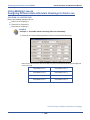
KSU ASSEMBLY – ADD-ON MODULES
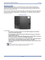
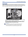
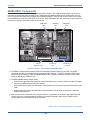
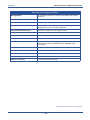
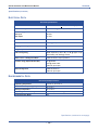
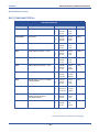
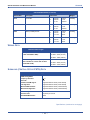
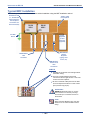
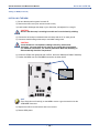
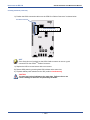
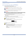
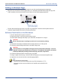
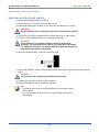
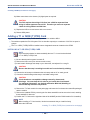
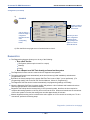
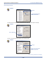
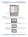
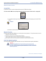
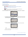
• Whenever you expand the DX-120 system, you install a module into one of the KSU cabinets.
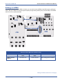
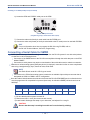
• Modules are connected to the various connectors on the 408M/E.
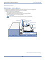
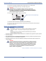
• Modules are mounted using standoff posts.
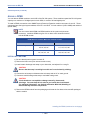
- Two standoff post sizes are used in the DX-120.
- The APM4 modules must be installed using the 2.5 cm (nickel) standoffs.
- All other modules use the 1.5 cm (brass) standoffs.
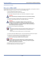
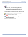
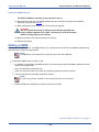
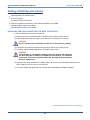
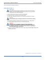
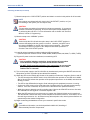
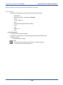
IMPORTANT!
Proper use of standoff is imperative to assure proper system operation.
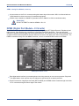
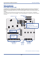
408M Connector
408E Connector to KSU2
VM/AAM Connector
T1 or ISDN (T1/PRI)
Connector
MDM Connectors
AAM Connector
CPM
Normal/Cold
Start Strap
SLOT 4
DPM8 (J3 Connector)
SLOT 3
DPM8 (J2 Connector)
SLOT 2 APM4 (Dedicated Cable)
SLOT 1
DPM8 on Board
COM4 or T1 OR ISDN (T1/PRI)
(Dedicated Cable)
408 M/E (KSU1/KSU2)
COM4 On Board
SLOT 5
SLOT 1
KSU Components (continued on next page)
- 51 -