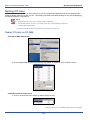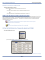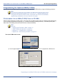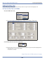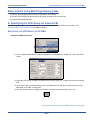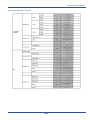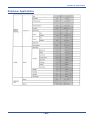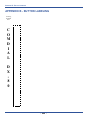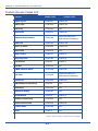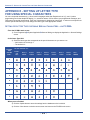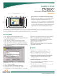
1
Programming Manual
Technical Manual - Volume II
DX-120 Programming Manual
Technical Manual - Volume II
Copyright © October, 2006 Vertical Communications, Inc.
All rights reserved. Unauthorized use of this document is prohibited.
Vertical Communications, Inc.
106 Cattlemen Road, Sarasota, FL 34243
(941)554-5000 or (800) 266-3425
-NoticeVertical Communications, the Vertical Communications logo and combinations thereof,
and Corporate Office are trademarks ofVertical Communications, Inc. Artisoft, TeleVantage, InstantOffice,
Comdial and Vertical Networks are registered trademarks of Artisoft, Inc.
All other brand and product names are used for identification only
and are the property of their respective holders.
.
DISCLAIMER
This manual has been developed by Vertical Communications, Inc. (the “Company”) and
is intended for the use of its customers, potential customers, and service personnel. The
information in this manual is subject to change without notice. While every effort has been
made to eliminate errors, the Company disclaims liability for any difficulties arising from
the interpretation of the information contained herein.
The information contained herein does not purport to cover all details or variations in
equipment or to provide for every possible contingency to be met in connection with installation, operation, or maintenance. Should further information be desired, or should particular problems arise which are not covered sufficiently for the purchaser’s purposes,
contact Vertical Communications, Inc.
DX-120 Programming Manual
TABLE OF CONTENTS
SECTION 1 - INTRODUCTION
OVERVIEW . . . . . . . . . . . . . . . . . . . . . . . . . . . . . . . . . . . . . . . . . . . . . . . . . . . . . . . . . . . . . . . . . .1
PROGRAMMING OPTIONS . . . . . . . . . . . . . . . . . . . . . . . . . . . . . . . . . . . . . . . . . . . . . . . . . . . . . . . .1
UPGRADING AN EXISTING SYSTEM . . . . . . . . . . . . . . . . . . . . . . . . . . . . . . . . . . . . . . . . . . . . . . . . .3
Converting a DX-80 Database to a DX-120 Database. . . . . . . . . . . . . . . . . . . . . . . . . . . . . . . . . . . 4
Programming a New System . . . . . . . . . . . . . . . . . . . . . . . . . . . . . . . . . . . . . . . . . . . . . . . . . . . . . . 7
SECTION 2 - PROGRAMMING OPTIONS
OVERVIEW . . . . . . . . . . . . . . . . . . . . . . . . . . . . . . . . . . . . . . . . . . . . . . . . . . . . . . . . . . . . . . . . . .9
PROGRAMMING VIA PC-DATABASE ADMINISTRATION (PC-DBA) . . . . . . . . . . . . . . . . . . . . . . . . . .9
PC-DBA Requirements . . . . . . . . . . . . . . . . . . . . . . . . . . . . . . . . . . . . . . . . . . . . . . . . . . . . . . . . . . 9
Loading PC-DBA Software. . . . . . . . . . . . . . . . . . . . . . . . . . . . . . . . . . . . . . . . . . . . . . . . . . . . . . . . 9
Programming Using PC-DBA. . . . . . . . . . . . . . . . . . . . . . . . . . . . . . . . . . . . . . . . . . . . . . . . . . . . . 10
Database Save and Restore . . . . . . . . . . . . . . . . . . . . . . . . . . . . . . . . . . . . . . . . . . . . . . . . . . . . . 12
Connecting PC-DBA to the Switch. . . . . . . . . . . . . . . . . . . . . . . . . . . . . . . . . . . . . . . . . . . . . . . . . 13
Changing Database Administrator Password . . . . . . . . . . . . . . . . . . . . . . . . . . . . . . . . . . . . . . . . 16
Receiving Data from the Switch . . . . . . . . . . . . . . . . . . . . . . . . . . . . . . . . . . . . . . . . . . . . . . . . . . . 18
Sending Data to the Switch . . . . . . . . . . . . . . . . . . . . . . . . . . . . . . . . . . . . . . . . . . . . . . . . . . . . . . 19
Disconnecting PC-DBA from the Switch . . . . . . . . . . . . . . . . . . . . . . . . . . . . . . . . . . . . . . . . . . . . 21
Initializing (F8) The System . . . . . . . . . . . . . . . . . . . . . . . . . . . . . . . . . . . . . . . . . . . . . . . . . . . . . . 21
Getting Help (F1) . . . . . . . . . . . . . . . . . . . . . . . . . . . . . . . . . . . . . . . . . . . . . . . . . . . . . . . . . . . . . . 24
USING ANY DIGITAL EXTENSION TELEPHONE (DET) . . . . . . . . . . . . . . . . . . . . . . . . . . . . . . . . . . 26
Entering the Database Administration Mode . . . . . . . . . . . . . . . . . . . . . . . . . . . . . . . . . . . . . . . . .
LCD Interactive Buttons . . . . . . . . . . . . . . . . . . . . . . . . . . . . . . . . . . . . . . . . . . . . . . . . . . . . . . . . .
Database Item Select Screen . . . . . . . . . . . . . . . . . . . . . . . . . . . . . . . . . . . . . . . . . . . . . . . . . . . .
Exiting Database Administration . . . . . . . . . . . . . . . . . . . . . . . . . . . . . . . . . . . . . . . . . . . . . . . . . .
Changing Database Administration Password. . . . . . . . . . . . . . . . . . . . . . . . . . . . . . . . . . . . . . . .
26
26
27
27
27
SECTION 3 - GETTING STARTED
OVERVIEW . . . . . . . . . . . . . . . . . . . . . . . . . . . . . . . . . . . . . . . . . . . . . . . . . . . . . . . . . . . . . . . . . 29
SHORTCUTS THAT HELP YOU WORK FASTER. . . . . . . . . . . . . . . . . . . . . . . . . . . . . . . . . . . . . . . . 29
Using a Database Programming Template . . . . . . . . . . . . . . . . . . . . . . . . . . . . . . . . . . . . . . . . . .
Copying Baseline CO Line Setups. . . . . . . . . . . . . . . . . . . . . . . . . . . . . . . . . . . . . . . . . . . . . . . . .
Feature / Directory Number Lookup. . . . . . . . . . . . . . . . . . . . . . . . . . . . . . . . . . . . . . . . . . . . . . . .
Resetting an Extension to the Default Set . . . . . . . . . . . . . . . . . . . . . . . . . . . . . . . . . . . . . . . . . . .
29
30
36
37
Table of Contents (continued on next page)
-1-
TABLE OF CONTENTS
DX-120 Programming Manual
Table of Contents (continued)
SECTION 4 - PROGRAMMING SYSTEM RESOURCES
OVERVIEW . . . . . . . . . . . . . . . . . . . . . . . . . . . . . . . . . . . . . . . . . . . . . . . . . . . . . . . . . . . . . . . . . 39
BASIC SYSTEM PROGRAMMING TASKS . . . . . . . . . . . . . . . . . . . . . . . . . . . . . . . . . . . . . . . . . . . . 39
Assigning Attendants . . . . . . . . . . . . . . . . . . . . . . . . . . . . . . . . . . . . . . . . . . . . . . . . . . . . . . . . . . .
Assigning System Reminders . . . . . . . . . . . . . . . . . . . . . . . . . . . . . . . . . . . . . . . . . . . . . . . . . . . .
Setting System Time, Date, and/or Hour Mode . . . . . . . . . . . . . . . . . . . . . . . . . . . . . . . . . . . . . . .
Setting Up Ring Scheme . . . . . . . . . . . . . . . . . . . . . . . . . . . . . . . . . . . . . . . . . . . . . . . . . . . . . . . .
Naming CO Lines. . . . . . . . . . . . . . . . . . . . . . . . . . . . . . . . . . . . . . . . . . . . . . . . . . . . . . . . . . . . . .
Setting Up Pre-Programmed Messages . . . . . . . . . . . . . . . . . . . . . . . . . . . . . . . . . . . . . . . . . . . .
Programming Speed Dial Numbers . . . . . . . . . . . . . . . . . . . . . . . . . . . . . . . . . . . . . . . . . . . . . . . .
Programming CID Names and Assignments Table . . . . . . . . . . . . . . . . . . . . . . . . . . . . . . . . . . . .
Assigning External Page . . . . . . . . . . . . . . . . . . . . . . . . . . . . . . . . . . . . . . . . . . . . . . . . . . . . . . . .
40
45
49
55
58
60
64
72
77
BASIC SYSTEM PROGRAMMING TASKS . . . . . . . . . . . . . . . . . . . . . . . . . . . . . . . . . . . . . . . . . . . . 77
Establishing Loud Bell Settings . . . . . . . . . . . . . . . . . . . . . . . . . . . . . . . . . . . . . . . . . . . . . . . . . . . 80
Establishing Music Sources . . . . . . . . . . . . . . . . . . . . . . . . . . . . . . . . . . . . . . . . . . . . . . . . . . . . . . 83
Assigning Ancillary Devices - Loud Bell, External Page, or Music on Hold . . . . . . . . . . . . . . . . . . 87
Assigning the DSS Port/Owner . . . . . . . . . . . . . . . . . . . . . . . . . . . . . . . . . . . . . . . . . . . . . . . . . . . 89
Setting Up Optional Internal Modem . . . . . . . . . . . . . . . . . . . . . . . . . . . . . . . . . . . . . . . . . . . . . . . 93
Specifying PC-DBA Transmit Rate . . . . . . . . . . . . . . . . . . . . . . . . . . . . . . . . . . . . . . . . . . . . . . . . 95
Selecting SMDR Transmit Rate . . . . . . . . . . . . . . . . . . . . . . . . . . . . . . . . . . . . . . . . . . . . . . . . . . . 97
Setting Up the CID Transfer Table. . . . . . . . . . . . . . . . . . . . . . . . . . . . . . . . . . . . . . . . . . . . . . . . 101
Customizing the Numbering Plan. . . . . . . . . . . . . . . . . . . . . . . . . . . . . . . . . . . . . . . . . . . . . . . . . 103
Phantom Lines / Virtual Numbers . . . . . . . . . . . . . . . . . . . . . . . . . . . . . . . . . . . . . . . . . . . . . . . . 113
SECTION 5 - PROGRAMMING C.O. LINES
OVERVIEW . . . . . . . . . . . . . . . . . . . . . . . . . . . . . . . . . . . . . . . . . . . . . . . . . . . . . . . . . . . . . . . . 115
BASIC CO LINE PROGRAMMING TASKS . . . . . . . . . . . . . . . . . . . . . . . . . . . . . . . . . . . . . . . . . . 115
Assigning the Tenant Group . . . . . . . . . . . . . . . . . . . . . . . . . . . . . . . . . . . . . . . . . . . . . . . . . . . .
Assigning the CO Line Group . . . . . . . . . . . . . . . . . . . . . . . . . . . . . . . . . . . . . . . . . . . . . . . . . . .
Setting the Day and Evening Class of Services (COS)
and Music On Hold (MOH) Source . . . . . . . . . . . . . . . . . . . . . . . . . . . . . . . . . . . . . . . . . . . . . .
Setting the Dial Type . . . . . . . . . . . . . . . . . . . . . . . . . . . . . . . . . . . . . . . . . . . . . . . . . . . . . . . . . .
Setting the CO Line Type. . . . . . . . . . . . . . . . . . . . . . . . . . . . . . . . . . . . . . . . . . . . . . . . . . . . . . .
Setting Call Abandon . . . . . . . . . . . . . . . . . . . . . . . . . . . . . . . . . . . . . . . . . . . . . . . . . . . . . . . . . .
Privacy and Enabling Privacy Release . . . . . . . . . . . . . . . . . . . . . . . . . . . . . . . . . . . . . . . . . . . .
Assigning Ring Type for the CO Line. . . . . . . . . . . . . . . . . . . . . . . . . . . . . . . . . . . . . . . . . . . . . .
Setting the Answer Position for Day and Evening . . . . . . . . . . . . . . . . . . . . . . . . . . . . . . . . . . . .
Setting CO Line Time Switching . . . . . . . . . . . . . . . . . . . . . . . . . . . . . . . . . . . . . . . . . . . . . . . . .
Setting the Pre-Defined Call Forward No Answer . . . . . . . . . . . . . . . . . . . . . . . . . . . . . . . . . . . .
Setting Up the PBX Code and Hunt Method . . . . . . . . . . . . . . . . . . . . . . . . . . . . . . . . . . . . . . . .
Setting Up the Alternate CO Line Group . . . . . . . . . . . . . . . . . . . . . . . . . . . . . . . . . . . . . . . . . . .
Setting Up FAX Detection . . . . . . . . . . . . . . . . . . . . . . . . . . . . . . . . . . . . . . . . . . . . . . . . . . . . . .
116
119
121
124
126
129
131
134
136
140
144
147
150
153
Table of Contents - Section 5 (continued on next page)
-2-
TABLE OF CONTENTS
DX-120 Programming Manual
Table of Contents - Section 5 (continued)
PROGRAMMING FOR THE OPTIONAL T1 AND ISDN (T1/PRI) CARDS . . . . . . . . . . . . . . . . . . . . . . 155
Programming for an Optional T1 Card . . . . . . . . . . . . . . . . . . . . . . . . . . . . . . . . . . . . . . . . . . . . . 155
Programming for Optional ISDN (T1/PRI) . . . . . . . . . . . . . . . . . . . . . . . . . . . . . . . . . . . . . . . . . . 164
Setting Up the Translation Table . . . . . . . . . . . . . . . . . . . . . . . . . . . . . . . . . . . . . . . . . . . . . . . . . 171
Setting Up Alternate Line IDs (ALI) for Systems with ISDN (T1/PRI) Installation Only 177
Programming Extensions for Alternate Line IDs 181
SECTION 6 - PROGRAMMING CALL HANDLING
OVERVIEW . . . . . . . . . . . . . . . . . . . . . . . . . . . . . . . . . . . . . . . . . . . . . . . . . . . . . . . . . . . . . . . . 187
BASIC CALL HANDLING PROGRAMMING TASKS . . . . . . . . . . . . . . . . . . . . . . . . . . . . . . . . . . . . .187
Ringing Line Priority . . . . . . . . . . . . . . . . . . . . . . . . . . . . . . . . . . . . . . . . . . . . . . . . . . . . . . . . . . .
Programming Conference Calls . . . . . . . . . . . . . . . . . . . . . . . . . . . . . . . . . . . . . . . . . . . . . . . . . .
Specifying CO Flash Time . . . . . . . . . . . . . . . . . . . . . . . . . . . . . . . . . . . . . . . . . . . . . . . . . . . . . .
Specifying PBX Flash Time . . . . . . . . . . . . . . . . . . . . . . . . . . . . . . . . . . . . . . . . . . . . . . . . . . . . .
Specifying Pause Time . . . . . . . . . . . . . . . . . . . . . . . . . . . . . . . . . . . . . . . . . . . . . . . . . . . . . . . .
Specifying Ring Abandon. . . . . . . . . . . . . . . . . . . . . . . . . . . . . . . . . . . . . . . . . . . . . . . . . . . . . . .
Setting Up Hold Remind. . . . . . . . . . . . . . . . . . . . . . . . . . . . . . . . . . . . . . . . . . . . . . . . . . . . . . . .
Selecting Exclusive Hold Time. . . . . . . . . . . . . . . . . . . . . . . . . . . . . . . . . . . . . . . . . . . . . . . . . . .
Establishing Warning Time for Limited Call Lengths . . . . . . . . . . . . . . . . . . . . . . . . . . . . . . . . . .
Setting Up Transfer Recalls for Idle and Busy Extensions. . . . . . . . . . . . . . . . . . . . . . . . . . . . . .
Setting Up Hold Recall . . . . . . . . . . . . . . . . . . . . . . . . . . . . . . . . . . . . . . . . . . . . . . . . . . . . . . . . .
Setting Up Dial Wait Time and Dial Delay . . . . . . . . . . . . . . . . . . . . . . . . . . . . . . . . . . . . . . . . . .
Establishing the Dialing Ratio . . . . . . . . . . . . . . . . . . . . . . . . . . . . . . . . . . . . . . . . . . . . . . . . . . .
Establishing Start and End of SLT Hook Flash . . . . . . . . . . . . . . . . . . . . . . . . . . . . . . . . . . . . . .
Programming Auto Redial . . . . . . . . . . . . . . . . . . . . . . . . . . . . . . . . . . . . . . . . . . . . . . . . . . . . . .
Programming External Call Forward . . . . . . . . . . . . . . . . . . . . . . . . . . . . . . . . . . . . . . . . . . . . . .
Setting Conference Talk Time Intervals and Conference Tones . . . . . . . . . . . . . . . . . . . . . . . . .
Setting Up Camp On Interval . . . . . . . . . . . . . . . . . . . . . . . . . . . . . . . . . . . . . . . . . . . . . . . . . . . .
Setting Up Alarm Play Intervals . . . . . . . . . . . . . . . . . . . . . . . . . . . . . . . . . . . . . . . . . . . . . . . . . .
Enabling/Disabling Hotel Feature. . . . . . . . . . . . . . . . . . . . . . . . . . . . . . . . . . . . . . . . . . . . . . . . .
Enabling/Disabling System Speed Toll Check . . . . . . . . . . . . . . . . . . . . . . . . . . . . . . . . . . . . . . .
Enabling/Disabling TSI Connection . . . . . . . . . . . . . . . . . . . . . . . . . . . . . . . . . . . . . . . . . . . . . . .
Enabling/Disabling Conference Tone. . . . . . . . . . . . . . . . . . . . . . . . . . . . . . . . . . . . . . . . . . . . . .
Specifying Call Duration Time . . . . . . . . . . . . . . . . . . . . . . . . . . . . . . . . . . . . . . . . . . . . . . . . . . .
Establishing Warning Time for Limited Call Lengths . . . . . . . . . . . . . . . . . . . . . . . . . . . . . . . . . .
Programming Caller ID Codes and Local Calling Areas . . . . . . . . . . . . . . . . . . . . . . . . . . . . . . .
Programming Tenant Groups. . . . . . . . . . . . . . . . . . . . . . . . . . . . . . . . . . . . . . . . . . . . . . . . . . . .
Setting Up SMDR Call Output . . . . . . . . . . . . . . . . . . . . . . . . . . . . . . . . . . . . . . . . . . . . . . . . . . .
Setting Fax Ring Time . . . . . . . . . . . . . . . . . . . . . . . . . . . . . . . . . . . . . . . . . . . . . . . . . . . . . . . . .
Setting Predefined Call Forward Time . . . . . . . . . . . . . . . . . . . . . . . . . . . . . . . . . . . . . . . . . . . . .
Setting Ring On Recognition Time Interval . . . . . . . . . . . . . . . . . . . . . . . . . . . . . . . . . . . . . . . . .
Setting the Daylight Savings Time Feature . . . . . . . . . . . . . . . . . . . . . . . . . . . . . . . . . . . . . . . . .
Setting Talk Abandon Time Interval . . . . . . . . . . . . . . . . . . . . . . . . . . . . . . . . . . . . . . . . . . . . . . .
188
189
193
196
199
202
205
207
210
213
217
220
223
228
232
237
241
245
247
249
252
254
256
258
261
264
271
274
280
282
285
287
289
Table of Contents - Section 6 (continued on next page)
-3-
TABLE OF CONTENTS
DX-120 Programming Manual
Table of Contents - Section 6 (continued)
Setting Hold Abandon Time Interval . . . . . . . . . . . . . . . . . . . . . . . . . . . . . . . . . . . . . . . . . . . . . .
Setting Unsupervised Talk Time . . . . . . . . . . . . . . . . . . . . . . . . . . . . . . . . . . . . . . . . . . . . . . . . .
Specifying CO Line Guard Time 296
Programming Auto Attendant Module (AAM). . . . . . . . . . . . . . . . . . . . . . . . . . . . . . . . . . . . . . . .
Setting Direct Inward System Access (DISA) . . . . . . . . . . . . . . . . . . . . . . . . . . . . . . . . . . . . . . .
291
294
298
312
T1 AND ISDN (T1/PRI) CALL OPERATION . . . . . . . . . . . . . . . . . . . . . . . . . . . . . . . . . . . . . . . . .320
T1 Call Operation . . . . . . . . . . . . . . . . . . . . . . . . . . . . . . . . . . . . . . . . . . . . . . . . . . . . . . . . . . . . . 320
ISDN (T1/PRI) Call Operation . . . . . . . . . . . . . . . . . . . . . . . . . . . . . . . . . . . . . . . . . . . . . . . . . . . 321
MULTIPLE CALL HANDLING (USING CALL KEYS FOR MANAGING MULTIPLE CALLS) . . . . . . . . . . . . . . 322
Multiple Call Handling - Incoming Calls . . . . . . . . . . . . . . . . . . . . . . . . . . . . . . . . . . . . . . . . . . . . 323
Multiple Call Handling - Outgoing Calls . . . . . . . . . . . . . . . . . . . . . . . . . . . . . . . . . . . . . . . . . . . . 323
Placing Call Key Calls on Hold. . . . . . . . . . . . . . . . . . . . . . . . . . . . . . . . . . . . . . . . . . . . . . . . . . . 324
Multiple Call Handling - Transferring Calls. . . . . . . . . . . . . . . . . . . . . . . . . . . . . . . . . . . . . . . . . . 325
Multiple Call Handling - Conference Calls . . . . . . . . . . . . . . . . . . . . . . . . . . . . . . . . . . . . . . . . . . 325
Multiple Call Handling - General Lamp Indicators . . . . . . . . . . . . . . . . . . . . . . . . . . . . . . . . . . . . 326
Hold Key Lamp Indicator . . . . . . . . . . . . . . . . . . . . . . . . . . . . . . . . . . . . . . . . . . . . . . . . . . . . . . . 326
SECTION 7 - PROGRAMMING TOLL RESTRICTIONS
OVERVIEW . . . . . . . . . . . . . . . . . . . . . . . . . . . . . . . . . . . . . . . . . . . . . . . . . . . . . . . . . . . . . . . . 329
BASIC TOLL RESTRICTION PROGRAMMING TASKS . . . . . . . . . . . . . . . . . . . . . . . . . . . . . . . . . . . 329
Class of Service and Digit Intervals . . . . . . . . . . . . . . . . . . . . . . . . . . . . . . . . . . . . . . . . . . . . . . . 329
Setting the Account Code Length and Password. . . . . . . . . . . . . . . . . . . . . . . . . . . . . . . . . . . . . 336
SECTION 8 - PROGRAMMING UCD GROUPS
OVERVIEW . . . . . . . . . . . . . . . . . . . . . . . . . . . . . . . . . . . . . . . . . . . . . . . . . . . . . . . . . . . . . . . . 341
CONTROLLING OVERFLOW AND REROUTE SITUATIONS . . . . . . . . . . . . . . . . . . . . . . . . . . . . . . . . 343
UCD AGENT LOG OFF/LOG ON . . . . . . . . . . . . . . . . . . . . . . . . . . . . . . . . . . . . . . . . . . . . . . . . 344
PROGRAMMING UCDS. . . . . . . . . . . . . . . . . . . . . . . . . . . . . . . . . . . . . . . . . . . . . . . . . . . . . . . . 345
SETTING UP UCD VOICE ANNOUNCE (VA) GROUPS . . . . . . . . . . . . . . . . . . . . . . . . . . . . . . . . . 358
SECTION 9 - PROGRAMMING VOICE MAIL 361
OVERVIEW . . . . . . . . . . . . . . . . . . . . . . . . . . . . . . . . . . . . . . . . . . . . . . . . . . . . . . . . . . . . . . . . 361
PROGRAMMING THIRD PARTY VOICE MAIL . . . . . . . . . . . . . . . . . . . . . . . . . . . . . . . . . . . . . . . . .362
Basic Programming for Third Party Voice Mail . . . . . . . . . . . . . . . . . . . . . . . . . . . . . . . . . . . . . .
A - Assigning the Voice Mail Port Type to the Appropriate Extensions . . . . . . . . . . . . . . . . . . . .
B - Program the UCD Group Members . . . . . . . . . . . . . . . . . . . . . . . . . . . . . . . . . . . . . . . . . . . .
C - Set Up the Voice Mail Table (Call Handling Digits) . . . . . . . . . . . . . . . . . . . . . . . . . . . . . . . .
D - Set the Voice Mail Dialing Ratio . . . . . . . . . . . . . . . . . . . . . . . . . . . . . . . . . . . . . . . . . . . . . . .
E- Activate Automated Attendant . . . . . . . . . . . . . . . . . . . . . . . . . . . . . . . . . . . . . . . . . . . . . . . . .
363
363
365
367
377
379
PROGRAMMING OPTIONAL INTERNAL DIGITAL VOICE MAIL 380
Basic Internal Voice Mail Programming Tasks. . . . . . . . . . . . . . . . . . . . . . . . . . . . . . . . . . . . . . .
A- Specifying the UCD Group . . . . . . . . . . . . . . . . . . . . . . . . . . . . . . . . . . . . . . . . . . . . . . . . . . .
B - Setting up the UCD Group in the Voice Mail Table . . . . . . . . . . . . . . . . . . . . . . . . . . . . . . . .
C- Activate Automated Attendant. . . . . . . . . . . . . . . . . . . . . . . . . . . . . . . . . . . . . . . . . . . . . . . . .
381
381
383
384
Table of Contents (continued on next page)
-4-
TABLE OF CONTENTS
DX-120 Programming Manual
Table of Contents (continued)
SECTION 10 - PROGRAMMING EXTENSIONS
OVERVIEW . . . . . . . . . . . . . . . . . . . . . . . . . . . . . . . . . . . . . . . . . . . . . . . . . . . . . . . . . . . . . . . . 385
REMINDER TONES . . . . . . . . . . . . . . . . . . . . . . . . . . . . . . . . . . . . . . . . . . . . . . . . . . . . . . . . . . . 385
BASIC EXTENSION PROGRAMMING TASKS . . . . . . . . . . . . . . . . . . . . . . . . . . . . . . . . . . . . . . . . . 386
Assigning a User Password, Password Length, and/or Name to Extensions . . . . . . . . . . . . . . .
Assigning Extensions to Tenant Groups . . . . . . . . . . . . . . . . . . . . . . . . . . . . . . . . . . . . . . . . . . .
Assigning Extensions to Pickup Groups . . . . . . . . . . . . . . . . . . . . . . . . . . . . . . . . . . . . . . . . . . .
Assigning Extensions to Paging Groups . . . . . . . . . . . . . . . . . . . . . . . . . . . . . . . . . . . . . . . . . . .
Assigning Extensions to a Class of Service . . . . . . . . . . . . . . . . . . . . . . . . . . . . . . . . . . . . . . . . .
Setting Up Monitoring Privileges . . . . . . . . . . . . . . . . . . . . . . . . . . . . . . . . . . . . . . . . . . . . . . . . .
Setting Up Intrusion Capabilities . . . . . . . . . . . . . . . . . . . . . . . . . . . . . . . . . . . . . . . . . . . . . . . . .
Setting up Warning Tones, Incoming Call Drops, Outgoing Call Drops . . . . . . . . . . . . . . . . . . . .
Setting Up Off Hook Voice Announce . . . . . . . . . . . . . . . . . . . . . . . . . . . . . . . . . . . . . . . . . . . . .
Setting Up Paging Privileges . . . . . . . . . . . . . . . . . . . . . . . . . . . . . . . . . . . . . . . . . . . . . . . . . . . .
Setting Up Call Forward – Extension Predefined. . . . . . . . . . . . . . . . . . . . . . . . . . . . . . . . . . . . .
Programming Extensions for SMDR Output . . . . . . . . . . . . . . . . . . . . . . . . . . . . . . . . . . . . . . . .
Assigning Recording Announcement Devices . . . . . . . . . . . . . . . . . . . . . . . . . . . . . . . . . . . . . . .
Assigning a Port Type . . . . . . . . . . . . . . . . . . . . . . . . . . . . . . . . . . . . . . . . . . . . . . . . . . . . . . . . .
Assigning Extensions to CO Lines . . . . . . . . . . . . . . . . . . . . . . . . . . . . . . . . . . . . . . . . . . . . . . . .
Setting Up Receive Assignments. . . . . . . . . . . . . . . . . . . . . . . . . . . . . . . . . . . . . . . . . . . . . . . . .
Setting Up Extension Ring Level . . . . . . . . . . . . . . . . . . . . . . . . . . . . . . . . . . . . . . . . . . . . . . . . .
Configuring Single Line Telephones (Analog Device Support) . . . . . . . . . . . . . . . . . . . . . . . . . .
Set Up Directory/Extension Swapping . . . . . . . . . . . . . . . . . . . . . . . . . . . . . . . . . . . . . . . . . . . . .
Assigning Feature Keys . . . . . . . . . . . . . . . . . . . . . . . . . . . . . . . . . . . . . . . . . . . . . . . . . . . . . . . .
Programming a Release Key . . . . . . . . . . . . . . . . . . . . . . . . . . . . . . . . . . . . . . . . . . . . . . . . . . . .
Flexible Feature Button Inquiry . . . . . . . . . . . . . . . . . . . . . . . . . . . . . . . . . . . . . . . . . . . . . . . . . .
Feature Key Reset . . . . . . . . . . . . . . . . . . . . . . . . . . . . . . . . . . . . . . . . . . . . . . . . . . . . . . . . . . . .
387
391
394
397
400
404
407
411
415
419
423
427
429
430
433
435
437
438
439
442
450
450
451
APPENDICES
APPENDIX A - WORKSHEETS . . . . . . . . . . . . . . . . . . . . . . . . . . . . . . . . . . . . . . . . . . . . . . . . . . . 453
Extension Data Programming . . . . . . . . . . . . . . . . . . . . . . . . . . . . . . . . . . . . . . . . . . . . . . . . . . .
CO Line Data Programming. . . . . . . . . . . . . . . . . . . . . . . . . . . . . . . . . . . . . . . . . . . . . . . . . . . . .
Call Handling . . . . . . . . . . . . . . . . . . . . . . . . . . . . . . . . . . . . . . . . . . . . . . . . . . . . . . . . . . . . . . . .
System Resources . . . . . . . . . . . . . . . . . . . . . . . . . . . . . . . . . . . . . . . . . . . . . . . . . . . . . . . . . . . .
Toll Restrictions . . . . . . . . . . . . . . . . . . . . . . . . . . . . . . . . . . . . . . . . . . . . . . . . . . . . . . . . . . . . . .
Extension Applications . . . . . . . . . . . . . . . . . . . . . . . . . . . . . . . . . . . . . . . . . . . . . . . . . . . . . . . . .
CO Applications . . . . . . . . . . . . . . . . . . . . . . . . . . . . . . . . . . . . . . . . . . . . . . . . . . . . . . . . . . . . . .
System Applications. . . . . . . . . . . . . . . . . . . . . . . . . . . . . . . . . . . . . . . . . . . . . . . . . . . . . . . . . . .
453
455
457
460
462
463
464
465
APPENDIX B - BUTTON LABELING . . . . . . . . . . . . . . . . . . . . . . . . . . . . . . . . . . . . . . . . . . . . . . . 468
APPENDIX C - FEATURE DIRECTORY AND CODE LISTS . . . . . . . . . . . . . . . . . . . . . . . . . . . . . . . . 471
Feature Directory Numbers List . . . . . . . . . . . . . . . . . . . . . . . . . . . . . . . . . . . . . . . . . . . . . . . . . . 471
Feature Access Codes List . . . . . . . . . . . . . . . . . . . . . . . . . . . . . . . . . . . . . . . . . . . . . . . . . . . . . 472
Suffix Codes List . . . . . . . . . . . . . . . . . . . . . . . . . . . . . . . . . . . . . . . . . . . . . . . . . . . . . . . . . . . . . 474
APPENDIX D - TRUNK DIRECTORY NUMBERS . . . . . . . . . . . . . . . . . . . . . . . . . . . . . . . . . . . . . . . 475
APPENDIX E - SETTING UP LETTER TYPE FOR USING SPECIAL CHARACTERS . . . . . . . . . . . . . . . 476
APPENDIX F - T1 MAINTENANCE . . . . . . . . . . . . . . . . . . . . . . . . . . . . . . . . . . . . . . . . . . . . . . . . 480
-5-
TABLE OF CONTENTS
DX-120 Programming Manual
-6-
DX-120 Programming Manual
SECTION 1 - INTRODUCTION
OVERVIEW
Once you have installed the system hardware, it is time to specify how you want the system to operate, using the
programmable DX-120 features. You need to set up the following:
• system settings such as system date and time, day/evening modes, and the numbering plan needed to meet your
customers' needs (“Section 4 - Programming System Resources” on page 39)
• the interface to the CO lines coming into the system (“Section 5 - Programming C.O. Lines” on page 115)
• how you want the system to handle and process calls (“Section 6 - Programming Call Handling” on page 187)
• any restrictions you want in place for toll calls (see “Section 7 - Programming Toll Restrictions” on page 329)
• Uniform Call Distribution - if applicable (see “Section 8 - Programming ucd groups” on page 341)
• internal or external voice mail - if applicable (see “Section 9 - Programming Voice Mail” on page 361)
• privileges for all extensions (see “Section 10 - Programming Extensions” on page 385)
• feature buttons on individual DET phones and DSS consoles (see “Section 10 - Programming Extensions” on
page 385)
PROGRAMMING OPTIONS
There are three approaches you can take when programming a DX-120 system. Each approach has its advantages
and disadvantages. You may prefer one approach and use it often, but you may occasionally need to use an
alternative approach. You can:
• Program the system on site using any Digital Extension Terminal (DET) phone.
• Program the system on site using PC-DBA, this Windows-based software program.
• Program the database using PC-DBA on a laptop prior to arriving at your customer’s site. Then when you arrive
on site, you can download the pre-programmed database into the DX-120 system in a minimal amount of time.
Advantages and Disadvantages of the Various Programming Methods
PROGRAMMING METHODS
Programming Interface
DET phone
Advantages
Disadvantages
• You do not need a laptop PC to
program the database.
• You have a limited visual interface
(the phone display) vs. a menu
screen.
• The phone is a direct interface to the
CPU, so there is no chance of
database corruption during
transmission. If you are having a
unidentifiable or persistent problem,
use DET phone programming to
eliminate the possibility of a corrupt
database.
• You have to do all programming on
site.
• DET phone programming can take
longer to perform than PC-DBA
programming.
• You cannot save the current switch
database. If you lose this database
because of battery failure or
because you have to perform a
Master Clear, you will have to
completely reprogram the database.
Advantages and Disadvantages of the Various Programming Methods (continued on next page)
- 1 -
PROGRAMMING OPTIONS
DX-120 Programming Manual
PROGRAMMING METHODS (continued)
Programming Interface
PC-DBA laptop on site
PC-DBA laptop remotely
Advantages
Disadvantages
• You can save the existing database
residing on the switch via a
RECEIVE ALL command. When
you need to modify the database,
you can use the switch version as a
basis so you will not have to
reprogram all its custom settings.
• You need a laptop with a serial port.
• If you lose the switch database
because of battery failure or
because you must perform a Master
Clear, you will NOT have to
completely reprogram the database
(provided you have previously saved
a copy of the custom switch
database onto your laptop).
• You do all programming on site.
• PC-DBA is not a direct interface to
the CPU. Therefore, the possibility
exists that a corruption can occur
when transmitting the laptop
database to the switch.
• You must be diligent in performing a
RECEIVE ALL when first arriving on
the customer site, and prior to
modifying their database. If you
neglect to do so, you may
inadvertently perform a SEND ALL
first, thus writing over their custom
programmed database with
whatever database you last used on
the laptop.
• You can program the customer’s
database while off site, and simply
download it to the switch when you
arrive on site. This reduces the
amount of time you have to spend
on site.
• You need a laptop with a serial port.
• You can save the existing database
residing on the switch via a
RECEIVE ALL command. When
you need to modify the database,
you can use the switch version as a
basis so you will not have to
reprogram all its custom settings.
• You must be diligent in performing a
RECEIVE ALL prior to modifying
their database. If you neglect to do
so, you may inadvertently perform a
SEND ALL first, thus writing over
their custom programmed database
with whatever database you last
used on the laptop.
• If you lose the switch database
because of battery failure or
because you must perform a Master
Clear, you will NOT have to
completely reprogram the database
(provided you have previously saved
a copy of the switch database on
your laptop).
- 2 -
• PC-DBA is not a direct interface to
the CPU. Therefore, the possibility
exists that a corruption can occur
when transmitting the database to
the switch.
UPGRADING AN EXISTING SYSTEM
DX-120 Programming Manual
UPGRADING AN EXISTING SYSTEM
Occasionally you may need to perform maintenance programming or install an upgrade to an existing system. The
information provides you with some of the issues you need to consider when maintenance or upgrading needs to be
performed on the current system:
• When you are upgrading an existing system, the database is already in place and functional.
• You may want to program your changes off-line using PC-DBA on a laptop, and then download the newly modified
database to the system.
• When you use this method, be sure to perform a RECEIVE ALL command first to overwrite the database currently
on your laptop with the database the switch is using.
• After receiving the database from the switch (see above item) make your programming changes to the laptop
database, and when you are finished perform a SEND ALL to upload the new modified version onto the DX-120
switch.
CAUTION
• If you fail to perform a RECEIVE ALL before you make your programming changes
and you then perform a SEND ALL, the system writes over the switch database
with whatever DX-120 database resides on your laptop.
• Use care that you do not overwrite the current site’s database with a database
residing on your laptop from your previous customer site.
• It is a good practice to always perform a RECEIVE ALL when first arriving at a new
customer site or prior to modifying your customer’s database.
• During a hardware upgrade, you need to add the new hardware and then program the corresponding feature set
in the existing database.
• There are specific procedures to follow when adding new hardware to an existing system. See the Vertical DX120 Installation and Maintenance Manual available on the Vertical CCC web site (www.vertical.com/ccc).
- 3 -
UPGRADING AN EXISTING SYSTEM
DX-120 Programming Manual
Converting a DX-80 Database to a DX-120 Database
A tool has been created that allows you to convert an existing DX-80 database for use in the DX-120DX-80 DB
Converter is a tool that allows you to convert DX-80 database files to DX-120 database files. This process MUST be
performed using PC-DBA only (i.e., you cannot convert the database using the DET).
There are two modules in this tool:
• Receive Data from the DX-80
• Convert F39 DB File to F03 DB File
RECEIVING DATA FROM THE DX-80
This module supports the following DX-80 versions F24 to F39 (including intermediate versions). It allows you to
transfer data from the DX-80 to a F39 DB file.
From the PC-DBA main screen:
1) Go to FileXNew Database to create a new database in the F39 format.
2) Go to ControlXConnect to open the connect screen.
3) Connect to the DX-80.
4) Go to ControlXReceive to start receiving data from DX-80.
After transfer of the data is complete:
5) Go to FileXSave as to save the database file in the appropriate location.
NOTE
In step 3, since some items do not exist in the database of old version KSU, some
messages, such as “CO Line Guard Time has not been received”, will be prompted
after data received from KSU. This may be due to missing items of some sort.
MISSING ITEMS IN DX-80 EARLIER THAN F39
• F24, F25 missing following items compared to F39:
-
SMDR call Output is not completely received.
-
CO Line Guard Time has not been received.
-
Daylight Savings Time has not been received.
-
CID Ring Time has not been received.
-
OHVA Accept has not been received.
-
OHVA Reject has not been received.
• F26 to F32 missing following items compared to F39:
-
SMDR call Output is not completely received.
-
CO Line Guard Time has not been received.
-
Daylight Savings Time has not been received.
-
CID Ring Time has not been received.
• F33 to F39 missing following items compared to F39:
-
SMDR call Output is not completely received.
-
CO Line Guard Time has not been received.
Converting A DX-80 Database to a DX-120 Database (continued on next page)
- 4 -
UPGRADING AN EXISTING SYSTEM
DX-120 Programming Manual
Converting A DX-80 Database to a DX-120 Database (continue)
CONVERTING AN F39 DB FILE TO AN F03 DB FILE
With the help of this module, users can convert a DB file in F39 format (e.g., a file created by using the module
“Receive Data from KSU”) to a DB file in F03 format.
From the PC-DBA main screen:
1) Go to ControlXConvert to open the DX-80 Converter screen.
2) Click "Select a DB file in F39 format".
3) Specify a path for the newly converted DB file.
4) Click "Convert” to begin the conversion.
NOTE
Please pay careful attention to any information that is displayed during the
conversion. Such information may be useful later on.
DIFFERENCES BETWEEN F39 AND F03
Version F03 contains the following items which should be set manually.
• SW/HW Revision
• Extension - ECF CO Group
• Extension -Force LCR
• Extension –Alternate Line ID Index
• Call Handing – LCR Timeout
• System Resource - Remote Ext Table
• System Resource - SPD NO.-C.O. Group
• System Resource - CID Transfer Table
• Restriction-Account Code Table - C.O Group
• Restriction-Account Code Table – LCR Enable
• Restriction - LCR-DGT Modification Table
• Restriction - LCR-DGT Comparison Table
• C.O.Line Application - T1 Card
• C.O.Line Application - Translation Table
• C.O.Line Application - ISDN
• C.O.Line Application – Alternate Line ID Table
• System Application –Numbering Plan- LCR Directory Number
• System Application–Numbering Plan - Remote Extension
Converting an F39 DB file to an F03 DB file (continued on next page)
- 5 -
UPGRADING AN EXISTING SYSTEM
DX-120 Programming Manual
Converting an F39 DB file to an F03 DB file (continued)
OTHER DIFFERENCES WHICH MAY AFFECT CONVERTING
• F39 has 60 Extensions while F03 has 120
• Only 60 Extensions settings will be copied to F03 database file. You should set others manually.
• F39 has 16 C.O.Line while F03 has 40 C.O. lines
• Only 16 C.O.Line settings will be copied to F03 database file. In the category Extension, only first 16 records
about “Receive Assign” and “Line Access Assign” will be copied. You should set others manually.
NOTE
C.O. lines for DX-120 are 800-839 (C.O. lines 840 through 843 are reserved for future
use).
• System Resource - SPD NO.
• Since the assignment of SPD NO. in F39 may causes conflict, some setting may be ignored. You'd better double
check it after converting
SOME ITEMS ARE NOT COPIED IN ORDER TO AVOID CONFLICT
These items should be set manually.
• C.O.Line - C.O.Group
• System Application – Numbering Plan
• C.O.Line - C.O.Group
• System Application – Numbering Plan
POSSIBLE ERRORS DURING CONVERSION
The following is a list of possible errors that may occur during the conversion of the DX-80 database. If any of these
occur, you will need to set the specified information manually.
INDEX
DESCRIPTION
C001
This item exists in F03, but not in F39.
C002
This item has probably been converted, but some conflict may generate because of the differences between F39 and F03. Double check it after converting, and set manually as needed.
C003
This item was not be converted because of the data conflict.
C004
Exception occurred during conversion.
- 6 -
UPGRADING AN EXISTING SYSTEM
DX-120 Programming Manual
Programming a New System
This manual provides information for completely programming a new DX-120 system from scratch. Vertical also
provides you with some tools you can use to reduce your programming time. These tools include:
• a series of worksheets for you to plan your system structure, and record the programming for future reference if
necessary. For more details, see Appendix A, Worksheets.
• copying a base CO line or extension’s setups to several other CO line or extensions thereby eliminating the need
to program them individually, and
• using one of four standard database programming templates provided with the DX-120 on CD part number DX120UTILCD. You can choose the template that most closely matches your new customer’s site needs, and then
add whatever custom changes you need to make. This approach saves you the time of programming the entire
system from scratch.
HINT
For more information on these and other aids the DX-120 provides to allow you to
program a system efficiently, see see “Shortcuts that Help You Work Faster” .
BASIC PROGRAMMING TASKS
When you are programming a new system from scratch, perform the following basic tasks:
A) Set up the system features (see “Section 4 - Programming System Resources” on page 39)
B) Set up the CO lines (see “Section 5 - Programming C.O. Lines” on page 115)
C) Set up call handling (see “Section 6 - Programming Call Handling” on page 187)
D) Set up the toll restrictions (see “Section 7 - Programming Toll Restrictions” on page 329)
E) Set up the UCD groups (see “Section 8 - Programming ucd groups” on page 341)
F) Set up Voice Mail - if applicable (see “Section 9 - Programming Voice Mail” on page 361)
G) Set up the extensions and program the feature buttons on the individual DET phones and DSS consoles (see
“Section 10 - Programming Extensions” on page 385)
USING SHORTCUTS
The DX-120 provides some shortcuts to help you perform these tasks efficiently.
EXAMPLE
When you are setting up the individual extensions, you can first set up a “base”
extension that is typical of how you will set up the majority of extensions. After you
have set up this base extension, you can copy its programming to all of the other
extensions in the system. Then, you can modify the few specific extensions that
require different programming.
The DX-120 provides a similar shortcut for setting up CO lines with a CO Line Copy command. For more details on
helpful shortcuts provided with your system, see see “Shortcuts that Help You Work Faster” .
Programming a New System (continued on next page)
- 7 -
UPGRADING AN EXISTING SYSTEM
DX-120 Programming Manual
Programming a New System (continued)
SETTING UP THE SYSTEM FEATURES FOR SYSTEM ADMINISTRATION AND RESOURCES
The system features allow you to control system administration and to assign system resources. Perform the following
tasks.
HINT
Details on how to perform these tasks are included in see “Overview” . The DX-120
provides programmable features that allow you to establish these various settings.
• Establish the database administrator password - see page 16
• Assign the attendant extension for each tenant group - see page40
• Assign the system reminder for each tenant group - see page45
• Set up the system time, date, and hour mode - see page49
• Set up the ring scheme - see page55
• Name each CO line - see page58
• Set up the pre-programmed incoming and outbound messages - see page60
• Program speed dial numbers - see page64
• Set the number of items in the Caller ID table - see page72
• Establish the music source for the each tenant group - see page83
• Assign the external pager ID to a tenant group - see page77
• Program ancillary devices - loud bell, external page, music on hold source - see page87
• Allocate the DSS - see page89
• Set up the optional internal modem - see page93
• Select the PC-DBA transmit rate - see page95
• Select the SMDR transmit rate - see page97
• Set up the numbering plan you want to use Set the user passwords and names for extensions - see page103
• Specify the letter type - see page476
• Set the user passwords and names for extensions - see page387
- 8 -
DX-120 Programming Manual
SECTION 2 - PROGRAMMING OPTIONS
OVERVIEW
There are two programming interfaces you can use to program the DX-120:
• PC-DBA
• Digital Extension Telephone (DET) - see page 26.
PROGRAMMING VIA PC-DATABASE ADMINISTRATION
(PC-DBA)
The DX-120 system allows you to administer system database parameters using any IBM® compatible Personal
Computer (PC).
The use of a PC has distinct advantages over programming the system using the digital telephone, including:
• specific database archiving (via save function),
• remote programming, and
• outboard programming (programming the system template in the PC memory, then downloading it to the DX-120
switch memory when ready).
The PC program that interfaces with the DX-120 system is called PC-Database Administration (PC-DBA).
PC-DBA Requirements
PC-DBA requires the following resources in the PC environment:
• PC running Microsoft® Windows 98, 2000, ME, or XP
• RAM: 64MB or greater.
• Processor Speed: 350 MHz or greater.
• Hard Disk Space: 4GB or greater.
IMPORTANT
You must have a well-rounded understanding of the Windows PC environment and
file structure to use this DX-120 utility. Vertical Communications, Inc. cannot support
users who are unfamiliar with these basic requirements. If any of these issues
concern you, program the DX-120 instead by using any DET phone.
Loading PC-DBA Software
When you download PC-DBA from the Vertical web site it is contained in an archived format to expedite the download.
Vertical recommends that you perform the following steps when downloading PC-DBA.
1) Create a separate directory on the PC where you can load PC-DBA (typically “DX-120”).
• This becomes the working directory.
2) Copy the archive file into that directory.
• An icon for the software will automatically be placed on your desktop. When you are ready to use PCDBA, you just need to double click on that icon to start the program.
- 9 -
PROGRAMMING VIA PC-DATABASE ADMINISTRATION (PC-DBA)
DX-120 Programming Manual
Programming Using PC-DBA
CAUTION!
The changes you make using PC-DBA are stored in a temporary working
directory. They are not uploaded to the DX-120 system memory until you
perform a SEND function. Do not forget this crucial step, or you may lose the
programming changes you just made.
1) Double click on the icon (see previous page) to display the main screen of PC-DBA.
2) Use the items in each of the menus to program the database (and switch) as needed.
Programming Using PC-DBA (continued on next page)
- 10 -
PROGRAMMING VIA PC-DATABASE ADMINISTRATION (PC-DBA)
DX-120 Programming Manual
Programming Using PC-DBA (continued)
PC-DBA MAIN MENUS
Review the following menus to become more familiar with where the various options are for using, programming, and
maintaining PC-DBA.
The File menu provides you with all the
basic functions of handling the DB file.
The Control menu provides you with the
capability to connect PD-DBA to the switch
for sending a receiving information.
The Send and Receive options will not be
available until successful connection has
been made between the PC-DBA and the
switch.
The Programming menu provides you
with a variety of programming options for
customizing the DB/system to work
efficiently and cohesively in the current
environment.
The Maintenance menu monitor and test
several aspects of the operation and use of
the database and system usage.
The Help menu gives you access to the online
help system that contains detailed
programming information (much like this
document). There is also an option that allows
you to view specific information about the PCDBA software (e.g., version, etc.).
- 11 -
PROGRAMMING VIA PC-DATABASE ADMINISTRATION (PC-DBA)
DX-120 Programming Manual
Database Save and Restore
The working directory is the location allocated in the PC for all changes while the PC-DBA programming session is in
progress. You may want to save the data in this directory for later retrieval since you may be working on many various
databases.
CAUTION!
Always perform a database SAVE prior to database RESTORE if you intend to
preserve the current contents of the working directory.
SAVING THE DATABASE
From the PC-DBA main screen:
1) Go to FileXSave As... to display the Save As dialog box.
• This dialog box allows you to enter a name for the database.
2) Enter the desired database name.
• You can also change the directory if necessary.
3) Click Save to store the database with that name.
• This dialog box allows you to select the desired database file.
4) Select (or enter the name of) the database you wish to restore.
5) Click Open to open the specified database.
• The system will use this database file until you specify a different name or close the application.
Database Save and Restore (continued on next page)
- 12 -
DX-120 Programming Manual
PROGRAMMING VIA PC-DATABASE ADMINISTRATION (PC-DBA)
Database Save and Restore (continued)
RESTORING (OPENING) A STORED DATABASE
From the PC-DBA main screen:
1) Go to FileXOpen Database... to display the Open dialog box.
• This dialog box allows you to select the desired database file.
2) Select (or enter the name of) the database you wish to restore.
3) Click Open to open the specified database.
• The system will use this database file until you specify a different name or close the application.
Connecting PC-DBA to the Switch
When using the programming options of PC-DBA, there are times when you need to send and receive information
between PC-DBA and the switch. However, before data can be exchanged between the PC and the DX-120 system,
you must make a connection between the two devices. This connection is a serial (RS-232 – COM port or modem)
link.
There are specific tasks that can only be performed after a successful connection between PC-DBA and the switch has
been made:
• Receiving (data from the switch) - see page18
• Sending (data to the switch) - see page19
• Initializing the System (cold and warm starts) - see page21
• Diagnostics and T1 Maintenance - see page480
•
HINT
Also see...For specific information about making a physical connection between
PC-DBA and the switch, be sure to review the Vertical DX-120 Installation and
Maintenance Manual available on the Vertical CCC web site (www.vertical.com/ccc).
Connecting PC-DBA to the Switch (continued on next page)
- 13 -
PROGRAMMING VIA PC-DATABASE ADMINISTRATION (PC-DBA)
DX-120 Programming Manual
Connecting PC-DBA to the Switch (continued)
Once you make this connection, you can connect to the DX-120 system processor and download (receive) the DX-120
database memory to the PC-DBA laptop working directory.
A connection can be made either on-site or remotely:
ON-SITE (CABLE) CONNECTION
While on-site, you can connect the PC to the DX-120 via a standard RS-232C “straight-through” cable. You can
connect the DX-120 system on site via the PC serial port (COM port). Use a straight-through 9-pin to 9-pin cable from
the PC serial port to the DX-120 CPM – PC-DBA port.
REMOTE (MODEM) CONNECTION
When you are accessing the system remotely you can make this connection via a modem.
1) Make the physical connection (cable or modem) between the PC and the DX-120 system.
From the PC-DBA main screen:
2) Go to ControlXConnect on the to display the password screen.
OR
Press F5 to display the password screen.
HINT
If the password screen does not appear, make sure that the physical connection is in
tact.
3) Enter the Database Administration password.
• At default, this password is eight spaces (i.e., press the space bar eight times).
• For information about changing the password, see “Changing Database Administrator Password” on
page 16.
- 14 -
DX-120 Programming Manual
PROGRAMMING VIA PC-DATABASE ADMINISTRATION (PC-DBA)
4) Click the OK button to display the next Connect screen that provides the current (local and remote)
settings for the connections.
5) Make any necessary changes to the connection settings (as described on next page):
IMPORTANT!
• For local settings, make sure that you have the appropriate Baud rate and COM
Port settings.
• For remote settings, make sure you have all the necessary modem settings
entered (including the init string, modem name, baud rate, and phone number).
HINT
Refer to the following pages:
• Setting Up Optional Internal Modem - page 93
• Specifying PC-DBA Transmit Rate - page 95
• Selecting SMDR Transmit Rate - page 97
AND/OR
Remote (modem) Connection (continued on next page)
- 15 -
PROGRAMMING VIA PC-DATABASE ADMINISTRATION (PC-DBA)
DX-120 Programming Manual
Remote (modem) Connection (continued)
Click Connect to being the connection process.
• Several brief messages will be displayed to let you know what's happening during this process (e.g.,
sending the password, connection request, successful connection).
• Once connection is successfully established, a red dot will appear in the lower left corner of the
screen...
A red dot appears here when
there is an active connection
between the PC-DBA and the
switch.
6) You can now perform any of the tasks listed above (e.g, Receive, Send, Diagnostics, Initialize, T1
Maintenance).
Changing Database Administrator Password
The DX-120 system allows you to set up and maintain the system database using any DX-120 DET telephone, once
you have entered the database administrator password. This password also allows you to program the system using
PC-DBA. It’s a good idea to change this password after the installation of the system.
Before changing the database administrator password, you must first connect to the DX-120 switch.
From the PC-DBA main screen:
1) Connect to PC-DBA to the switch (see 13).
2) Go to ProgrammingXKSU DB Password to display the password change screen.
3) Enter the existing (old) password.
• When you enter text in this field, a new field will appear (i.e., New Password).
Changing Database Administrator Password (continued on next page)
- 16 -
PROGRAMMING VIA PC-DATABASE ADMINISTRATION (PC-DBA)
DX-120 Programming Manual
Changing Database Administrator Password (continued)
4) Enter the new password.
• When you enter text in this field, a new field will appear (i.e., Confirm Password).
5) Enter the new password again to confirm it.
• When you enter text in this field, an OK button will appear.
6) Click OK to change the password as designated in the previous steps.
• A message will appear to ask you to confirm that you want to make the change.
7) Click Yes to change the password and display a confirmation as the password is successfully changed.
HINT
Also see “Changing Database Administrator Password” on page 16.
- 17 -
PROGRAMMING VIA PC-DATABASE ADMINISTRATION (PC-DBA)
DX-120 Programming Manual
Receiving Data from the Switch
Before data can be exchanged between PC-DBA and the DX-120 system, you must Connect (F5) to the switch. After
you establish a successful connection between the DX-120 processor and the PC-DBA software, the system displays
the word Connect at the bottom of the screen, next to the time and date.
CAUTION!
• When you receive programming from the switch, the system overwrites the
corresponding programming on your PC with the settings from the switch.
Make sure you want to do this before proceeding.
• Always perform a Database Save (All) before a Database Receive (All)
operation if you want to preserve the current contents of the working
directory on the laptop.
• It is recommended that if you are making database changes to a system that
has been in operation for an extended period of time, that you perform a
Receive All operation prior to making any database changes on the laptop.
• Since some database fields (including Speed Dial and Service Mode) are
user adjustable, these fields will be overwritten if you perform a Send All
operation using an outdated PC-DBA laptop database.
From the PC-DBA main screen:
1) Connect PC-DBA to the switch.
2) Go to ControlXReceive to display a list of categories that represent the information that can be received.
OR
Press F3 to display a list of categories that represent the information that can be received.
3) Locate the category that represents the information you want to receive.
4) Click the Items button to display the list of various options for that category.
Receiving Data from the Switch (continued on next page)
- 18 -
PROGRAMMING VIA PC-DATABASE ADMINISTRATION (PC-DBA)
DX-120 Programming Manual
Receiving Data from the Switch (continued)
5) Click on the specific items you want to receive to select them.
OR
Click Select All to select all the items on that screen.
• Use the Unselect All button to deselect all items on the page. You can then reselect any specific items
as needed.
6. Click OK when all your selections have been made to begin the receiving process and download the
data from the switch to your PC/laptop.
HINT
Refer to the following pages:
• Connecting PC-DBA and the Switch - page 13
• Sending Data to the Switch - page 19
• Disconnecting PC-DBA from the Switch - page 21
Sending Data to the Switch
Before data can be exchanged between PC-DBA and the DX-120 system, you must Connect (F5) to the switch. After
you establish a successful connection between the DX-120 processor and the PC-DBA software, the system displays
the word Connect at the bottom of the screen, next to the time and date.
CAUTION!
• When you receive programming from the switch, the system overwrites the
corresponding programming on your PC with the settings from the switch.
Make sure this is what you want to do before proceeding.
• Always perform a Database Save (All) before a Database Receive (All)
operation if you want to preserve the current contents of the working
directory on the laptop.
• It is recommended that if you are making database changes to a system that
has been in operation for an extended period of time, that you perform a
Receive All operation prior to making any database changes on the laptop.
• Since some database fields (including Speed Dial and Service Mode) are
user adjustable, these fields will be overwritten if you perform a Send All
operation using an outdated PC-DBA laptop database.
From the PC-DBA main screen:
1) Connect PC-DBA to the switch.
2) Go to ControlXSend to display a list of categories that represent the information that can be sent.
OR
Sending Data to the Switch (continued on next page)
- 19 -
PROGRAMMING VIA PC-DATABASE ADMINISTRATION (PC-DBA)
DX-120 Programming Manual
Sending Data to the Switch (continued)
3) Press F4 to display a list of categories that represent the information that can be sent.
Click on these buttons to
display the list of options for
the corresponding category.
4) Locate the category that represents the information you want to receive.
5) Click the Items button to display the list of various options for that category.
6) Click on the specific items you want to receive to select them.
OR
7) Click Select All to select all the items on that screen.
• Use the Unselect All button to deselect all items on the page. You can then reselect any specific items
as needed.
8) Click OK when all your selections have been made to begin the receiving process and download the data
from the switch to your PC/laptop.
HINT
Refer to the following pages:
• Connecting PC-DBA and the Switch - page 13
• Receiving Data from the Switch - page 18
• Disconnecting PC-DBA from the Switch - page 21
- 20 -
DX-120 Programming Manual
PROGRAMMING VIA PC-DATABASE ADMINISTRATION (PC-DBA)
Disconnecting PC-DBA from the Switch
After you have finished using the link between the DX-120 and PC-DBA, you should disconnect this link. The system
can be disconnected either automatically or manually:
AUTOMATIC DISCONNECTION
The system disconnects automatically if:
• the physical connection path (cable or modem connection) is interrupted (not recommended)
• you exit PC-DBA while the link is active (not recommended)
• after several minutes it senses that someone has not been using the associated tools that require connection (i.e.,
it automatically times itself out).
MANUAL DISCONNECTION
From the PC-DBA main screen:
1) Go to ControlX Disconnect to disconnect the system from the switch.
OR
2) Press F7 to disconnect the system from the switch.
Once this disconnection is complete:
3) Disconnect any physical connection (cable or modem) between the PC and the switch system as
appropriate.
Initializing (F8) The System
In the programming process it is often desirable to revert to factory defaults (cold start). The Initialize function allows
you to revert the database settings to the factory defaults. While using the various database programming menus, you
can click the Initialize button or press F8 to initialize the current category.
Keep in mind that when you use Initialize, the system saves the restored data only when you exit the screen you are
on. The system then only sends it to the DX-120 switch database when you perform the F4-Send operation.
You can also initialize (i.e., reset) the system without reverting back to factory defaults and reloading the database
(warm start).
NOTE
You can initialize all of the PC-DBA parameters when you install a new system. After
you perform a cold start, connect to the DX-120 processor by clicking Connect or
pressing F5. Then click Receive or press F3 to perform a Receive All and download
all factory settings to a new database file on the PC.
HINT
Also refer to the Vertical DX-120 Installation and Maintenance Manual which can be
found on the Vertical CCC website (www.vertical.com/service-login.html).
Initializing the System (continued on next page)
- 21 -
PROGRAMMING VIA PC-DATABASE ADMINISTRATION (PC-DBA)
DX-120 Programming Manual
Initializing the System (continued)
PERFORMING A COLD START
Use Software COLD Start to cause the system to restart operations and reload default customer database data.
CAUTION
USE THIS FEATURE WITH CARE!
This operation requires confirmation since all calls in progress will be
disconnected and the current database will be erased!
NOTE
Once you run this operation, connection between the switch and PC-DBA will be lost.
Therefore, you will have to re-connect to the switch.
After you connect the PC-DBA to the switch:
From the main PC-DBA Screen:
1) Go to MaintenanceXRemote ControlXSoftware Cold Start to display a prompt warning you about what
will happen if you continue with this process (i.e. programming operations will be lost, then returned to
default settings).
2) Click Yes to execute the Cold Start.
• A message will appear to confirm that a cold start was successfully completed.
OR
Click No to cancel the Cold Start and close the warning prompt.
3) Click OK to close the window.
HINT
Also refer to the Vertical DX-120 Installation and Maintenance Manual which can be
found on the Vertical CCC website (www.vertical.com/service-login.html).
- 22 -
DX-120 Programming Manual
PROGRAMMING VIA PC-DATABASE ADMINISTRATION (PC-DBA)
PERFORMING A WARM START
Use the Warm Start process to cause the system to restart its operations without reloading or affecting the stored
database (e.g., if some how one or more ports lock up, etc.).
CAUTION
USE THIS FEATURE WITH CARE!
This operation requires confirmation since all calls in progress will be
disconnected.
NOTE
Once you run this operation, connection between the switch and PC-DBA will be lost.
Therefore, you will have to re-connect to the switch.
After you connect the PC-DBA to the switch:
From the main PC-DBA Screen:
1) Go to MaintenanceXRemote ControlXSoftware Warm Start to display a prompt warning you about what
will happen if you continue with this process. (i.e., all system process will be discontinued and any calls in
progress will be disconnected).
2) Click Yes to execute the Warm Start.
• At the end of the process a message will appear to confirm that a warm start was successfully
completed.
OR
Click No to cancel the Warm Start and close the warning prompt.
3) Click OK to close the window.
HINT
Also refer to the Vertical DX-120 Installation and Maintenance Manual which can be
found on the Vertical CCC website (www.vertical.com/service-login.html).
- 23 -
PROGRAMMING VIA PC-DATABASE ADMINISTRATION (PC-DBA)
DX-120 Programming Manual
Getting Help (F1)
You can access Help via the main menu bar or from any screen within the program.
From the PC-DBA main screen:
Click here to display a list of options.
OR
Click here to display the first page of the online help.
1) Click on the Help option on the main menu bar.
HINT
You can also click on
to display the first page of the online help (then, skip to step 3).
2) Selecting Contents to display the main Help screen.
• If you select About PC-DBA you will get information about the version of PC-DBA currently running on
your system.
3) Use the tabs (Contents, Search, Index) to find a specific topic for which you need help.
OR
Getting Help (continued on next page)
- 24 -
DX-120 Programming Manual
PROGRAMMING VIA PC-DATABASE ADMINISTRATION (PC-DBA)
Getting Help (continued)
From a specific screen within the program:
1) Press F1 for any individual screen within the program to display the corresponding page from Help for that
screen.
OR
2) Click
on any individual screen within the program to display Help for that screen.
EXAMPLE
1
Click on the Help button
from any screen...
2
...to display the corresponding page in online help.
HINT
If you are unable to find the information you need in the Help system, contact Vertical
Technical Support for assistance.
- 25 -
USING ANY DIGITAL EXTENSION TELEPHONE (DET)
DX-120 Programming Manual
USING ANY DIGITAL EXTENSION TELEPHONE (DET)
The DX-120 system allows you to program system database parameters using any DX-120 DET. It is possible to
program the DX-120 system while the telephone is in use; however, certain button operations are used during
programming and cannot be used for telephone call processing. Therefore, Vertical suggests not using these features
simultaneously unless you have been directed to do so by the servicing technician.
The Database Administration password is set by default to ######## (eight #s). You can use any combination of
alphanumeric characters using the conventions of extension/CO line name.
Entering the Database Administration Mode
1) Press Feature, then # * to enter Database Administration.
• The system then prompts for the system Database Administration password.
• The default set at the factory is ########.
2) Enter the password and press show (show is an LCD interactive button).
• After you have correctly entered the password, the system gives you access to Database
Administration.
• You can also change the password at any time - see “Changing Database Administration Password” on
page 27.
LCD Interactive Buttons
The LCD interactive buttons are essential to completing database programming tasks. These buttons take on many
functions while in the database administration mode. LCD interactive buttons include the following.
• next —moves the cursor to the next item or parameter
• back—moves the cursor back one item or parameter
• show—shows the contents of the current item or parameter
• chg—changes the contents of the current item or parameter
• bksp—when you are entering data, backspaces over what you entered so you can correct it
• save—saves entered data
- 26 -
USING ANY DIGITAL EXTENSION TELEPHONE (DET)
DX-120 Programming Manual
Database Item Select Screen
After you enter the correct password and press show, the system opens DX-80 Database Administration and displays
the Database Item Select screen. This screen allows you to skip to the necessary database item for immediate
programming of that item. The coding instructions you enter for each database item correspond to the following list:
To Program
Enter
EXTENSION
01-
CO LINE
02-
CALL HANDLING
03-
SYSTEM RESOURCE
04-
RESTRICTION
05-
EXTENSION APPLICATION
06-
CO LINE APPLICATION
07-
SYSTEM APPLICATION
08-
EXAMPLE
To skip to the extension application section of database administration, enter 06 at
the DB Item Select screen and press save. If you want instead to go to system
resources, enter 04 at the DB Item Select screen and press save.
Exiting Database Administration
To exit the Database Administration when you are finished programming or need to perform another task (e.g., make a
phone call):
Press the SPK button twice.
OR
Lift and replace the handset in the hook-switch cradle.
Changing Database Administration Password
1) Press Feature, then # * to enter Database Administration.
• The system then prompts for the system Database Administration password.
• The default set at the factory is ########.
2) Press show to display the DB Item Select screen.
3) Enter 04-01.
4) Press save to display to the System Resources – DB PSWD screen with the current password.
5) Press chg to change the password.
6) Enter a new eight-character, alphanumeric password.
IMPORTANT!
Press # after entering each character that makes up the password.
7) Press save.
8) Exit the programming mode.
- 27 -
THIS PAGE INTENTIONALLY LEFT BLANK
DX-120 Programming Manual
SECTION 3 - GETTING STARTED
OVERVIEW
Before beginning to program a new system, it is important that you determine what configuration will best meet your
customer’s needs.
The DX-120 Numbering Plan contains all of the configuration defaults provided with the system. If you need settings
other than those provided, you will need to customize the Numbering Plan. Since you will be programming aspects
that can be affected by the Numbering Plan, it is best to customize the plan before programming the remainder of the
system. For details on modifying the default Numbering Plan see “Customizing the Numbering Plan” on page 103.
SHORTCUTS THAT HELP YOU WORK FASTER
Vertical also provides you with some tools you can use to reduce your programming time. These tools include:
• a series of worksheets for you to plan your system structure, and to record the programming for future reference if
necessary. These worksheets are provided in Appendix A, Worksheets.
• using one of four standard database programming templates provided with the DX-120 product CD. You can
choose the template that most closely matches your new customer’s site needs, and then add whatever custom
changes you need to make. This approach saves you the time of programming the entire system from scratch.
• copying a baseline CO line or extension’s setups to several other CO line or extensions, thereby eliminating the
need to program them individually.
• using the directory number/feature number lookup when you need to know a specific directory number or feature
code you need to enter at the DET speakerphone, and
• resetting an extension to its default settings during troubleshooting and fault isolation procedures.
• In addition, button label templates for customizing individual DET button definitions are provided in Appendix B,
Button Labeling.
Using a Database Programming Template
Six programming templates have been provided that you may use as a shortcut when setting up your customer’s
database; one template with no voice mail and five templates with voice mail options.
• You can copy the template that is closest to your customer’s requirements, and then customize it further if
necessary to further meet their needs.
• These six database templates are provided on the DX-120 product CD.
• While you are not allowed to modify the templates on the CD, you can download them to your laptop and then
customize them further as needed.
CAUTION
• These templates are provided to reduce your programming time when
setting up a new system. You can use them for existing systems, but you will
lose whatever custom settings are currently in place on that system.
• Be aware of this when downloading a template from PC-DBA to an existing
system with a lot of customized features, as you will have to reprogram
those features.
HINT
For further details on using the database templates, refer to the Read Me file on the
DX-120 product CD.
- 29 -
SHORTCUTS THAT HELP YOU WORK FASTER
DX-120 Programming Manual
Copying Baseline CO Line Setups
This is a programming aid feature. Once you have programmed one CO line for the baseline configuration settings,
you can copy those setting to other CO lines using this utility. Copying these setups requires two separate procedures
whether you program via PC-DBA or by DET:
You must:
A) Program the CO Line Setup to be copied
B) Copy the programmed CO Line Setup - Setups can be copied one line at a time or several lines at a time
COPYING BASELINE CO LINE SETUPS VIA PC-DBA
PROGRAM THE CO LINE SETUP TO BE COPIED
See “Section 5 - Programming C.O. Lines” for additional information about programming C.O. lines
COPY THE PROGRAMMED CO LINE SETUP
From the PC-DBA main screen:
1) Go to ProgrammingXSystem ApplicationXConfiguration Copy to display the Configuration Copy screen.
Copy the line(s) as needed:
Copy CO Lines One at a Time
2) Locate the Individual area under CO Line Copy.
3) Select the CO line directory number you want to use as a baseline from the dropdown list in the Source
DIR No. field.
• Valid directory numbers are 800 through 839.
• There is no default.
4) Select the CO line directory number into which you want to copy the baseline’s programming (800-839) in
the Destination DIR No. field.
5) Click Copy to make the specified copy.
• Enter any other CO line numbers as needed using the steps above.
• If needed, you can enter another source CO line directory number to copy from, and continue the
process for other CO lines.
Now... continue on to step 6 on the following page.
OR
Copy the Programmed CO Line Setup via PC-DBA (continued on next page)
- 30 -
SHORTCUTS THAT HELP YOU WORK FASTER
DX-120 Programming Manual
Copy the Programmed CO Line Setup via PC-DBA (continued)
Copy a CO Line Setup to All the Lines in a Line Group
2) Locate the Group area under CO Line Copy.
3) Select the CO line directory number you want to use as a baseline from the dropdown list in the Source
DIR No. field.
• Valid directory numbers are 800 through 839.
• There is no default.
4) Select the CO group number into which you want to copy the baseline’s programming (9 and 740 through
746) in the CO Group field.
5) Click Copy to make the specified copy.
• Enter any other CO group numbers as needed using the steps above.
Now... continue on to step 6 below.
When all copies have been made:
6) Click the Update button to enter and save your settings into the database on your local disk.
7) Click the Close button to exit the current screen and return to the PC-DBA main screen.
Once all database changes have been completed:
8) Perform a SEND to copy the database changes to the DX-120 switch system memory.
COPYING BASELINE CO LINE SETUPS VIA THE DET
PROGRAM THE CO LINE SETUP TO BE COPIED
See “Section 5 - Programming C.O. Lines” for additional information about programming C.O. lines
COPY THE PROGRAMMED CO LINE SETUP
NOTE
• chg, bksp, save, one, always, del, and ack are interactive LCD button operations.
Use the three buttons below the LCD display to activate the associated operation.
• You can press Hold at any time to return to the previous level or press the volume
buttons to return to the main DB selection screen.
1) Enter Database Administration (see page 26) using the feature code Feature # * to display a prompt for
the password.
2) Enter the DB Admin password.
Copy the Programmed CO Line Setup via the DET (continued on next page)
- 31 -
SHORTCUTS THAT HELP YOU WORK FASTER
DX-120 Programming Manual
Copy the Programmed CO Line Setup via the DET (continued)
Copy CO Lines One at a Time
3) Enter 08-11-01.
4) Press save to display the Individual CO Line Copy screen.
5) Press show to display the prompt: “COPY FROM”.
6) Enter the CO line directory number you want to use as a baseline.
7) Press save to display the prompt “COPY TO”.
8) Enter the CO line directory number you want to copy the baseline’s programming into (800-839).
9) Press save to store the copy and again display the prompt “COPY TO”.
• Continue entering CO line directory numbers CO lines to which you want to copy the baseline setups.
• Press save each time you enter a directory number.
10) Press the Hold button to return to the previous menu level.
OR
Press the Volume button (up or down) to return to the DB Item Selection screen.
OR
Exit programming (see “Exiting Database Administration” on page 27).
Copy a CO Line Setup to All the Lines in a Line Group
3) Enter 08-11-02.
4) Press save to displays the Group CO Line Copy screen.
5) Press show to display the prompt: “COPY FROM”.
6) Enter the CO line directory number you want to use as a baseline.
7) Press save to display the prompts “COPY TO”.
8) Enter the CO line group directory number into which you want to copy the baseline’s programming (9,
740-746).
9) Press save to store the setups to all of the CO lines that are part of that CO line group.
• The system prompts “COPY TO” again so that you can save the setups to another line group if desired.
• Continue entering CO line group directory numbers where you want to save the baseline setup.
• Press save each time you enter a CO line group directory number.
10) Press the Hold button to return to the previous menu level.
OR
Press the Volume button (up or down) to return to the DB Item Selection screen.
OR
Exit programming (see “Exiting Database Administration” on page 27).
Copy the Baseline Setups (continued on next page)
- 32 -
SHORTCUTS THAT HELP YOU WORK FASTER
DX-120 Programming Manual
Copy Baseline Setups (continued)
COPYING BASELINE EXTENSION SETUPS
You can use this database feature to quickly copy the various programming and settings for one extension to other
extensions. Copying these setups requires two separate procedures whether you program via PC-DBA or by DET:
You must:
A) Program the Baseline Extension Setup to be copied
B) Copy the programmed Baseline Extension Setup - Setups can be copied one line at a time or several lines at a
time
COPYING BASELINE EXTENSION SETUPS VIA PC-DBA
PROGRAM THE BASELINE EXTENSION SETUP TO BE COPIED
See page “Section 10 - Programming Extensions” on page 385 for information about programming baseline
extensions.
NOTE
When using group copy, all extensions you want to receive the programming must be
programmed for the same pickup group.
From the PC-DBA main screen:
1) Go to ProgrammingXSystem ApplicationXConfiguration Copy to display the Configuration Copy screen.
Copy the line(s) as needed.
Copy Individual Extension Settings
2) Locate the Individual area under Extension Copy.
3) Select the extension directory number you want to use as a baseline from the dropdown list in the Ext DIR
No. field.
• You can enter any valid extension number in the system.
• There is no default.
4) Select the extension directory number (from the Ext DIR No. field to the right of the arrow) into which you
want to copy the baseline’s programming (i.e., any valid extension).
5) Click on Copy to copy the specified settings.
• Enter any other extension numbers as needed using the steps above.
• If needed, you can enter another source extension number to copy from, and continue the process for
other extensions.
Now... continue on to step 6 on the next page.
OR
Copy the Programmed CO Line Setup via PC-DBA (continued on next page)
- 33 -
SHORTCUTS THAT HELP YOU WORK FASTER
DX-120 Programming Manual
Copy the Programmed CO Line Setup via PC-DBA (continued)
Copy All Lines in a Pickup Group
2) Locate the Group area under Extension Copy.
3) Select the extension number you want to use as a baseline from the dropdown list in the Ext DIR No. field.
• You can enter any valid extension number in the system.
• There is no default.
4) Select the pickup group number (from the Pickup Group field) into which you want to copy the baseline
programming (i.e., any valid pickup directory number).
5) Click on Copy to make the specified copy.
• Enter any other pickup group numbers as needed using the steps above.
• If needed, you can enter another source extension directory number to copy from, and continue the
process for other pickup groups.
Now... continue on to step 6 on the next page.
When all extensions or pickup group settings are copied:
6) Click the Update button to enter your settings into the database on your local disk.
7) Click the Close button to exit the current screen and return to the PC-DBA main screen.
When you have finished all programming changes:
8) Perform a SEND to copy the database changes to the DX-120 switch system memory.
COPYING BASELINE EXTENSION SETUPS VIA THE DET
PROGRAM THE CO LINE SETUP TO BE COPIED
“Section 5 - Programming C.O. Lines” for detailed information about programming C.O. lines
COPY THE PROGRAMMED CO LINE SETUP
NOTE
• chg, bksp, save, one, always, del, and ack are interactive LCD button operations.
Use the three buttons below the LCD display to activate the associated operation.
• You can press Hold at any time to return to the previous level or press the volume
buttons to return to the main DB selection screen.
1) Enter Database Administration (see page 26) using the feature code Feature # * to display a prompt for
the password.
2) Enter the DB Admin password.
Copy the Programmed Baseline Extension Setups via the DET (continued on next page)
- 34 -
SHORTCUTS THAT HELP YOU WORK FASTER
DX-120 Programming Manual
Copy the Programmed Baseline Extension Setups via the DET (continued)
Copy Individual Extension Settings
3) Enter 08-12-01.
4) Press save to display the “INDIVIDUAL COPY” programming screen.
5) Press show to display the prompt: “COPY FROM”.
6) Enter the extension directory number you want to use as a baseline.
7) Press save to display the prompt: “COPY TO”.
8) Enter the extension number into which you want to copy the baseline setups into.
9) Press save to store the copy and again display the prompt “COPY TO”.
• Use the steps above to copy other extensions as needed.
• Press save each time you copy an extension.
10) Press the Hold button to return to the previous menu level.
OR
Press the Volume button (up or down) to return to the DB Item Selection screen.
OR
Exit programming (see “Exiting Database Administration” on page 27).
Copy All Lines in a Pickup Group
1) Enter 08-12-02.
2) Press save to display the “GROUP COPY” programming screen.
3) Press show to display the prompt: “COPY FROM”.
4) Enter the extension directory number you want to use as a baseline.
5) Press save to display the prompt: “COPY TO”.
6) Enter the pickup group number into which you want to copy the baseline setups into.
7) Press save to copy the programming of the baseline extension into all the extensions in the specified
pickup group and again display the prompt: “COPY TO”.
• Use the steps above to copy programming to other pickup groups.
8) Press the Hold button to return to the previous menu level.
OR
Press the Volume button (up or down) to return to the DB Item Selection screen.
OR
Exit programming (see “Exiting Database Administration” on page 27).
- 35 -
SHORTCUTS THAT HELP YOU WORK FASTER
DX-120 Programming Manual
Feature / Directory Number Lookup
The DX-120 system has many features and codes, and at times it may be difficult to remember the code for the
necessary feature. The DX-120 has a built-in feature code directory to allow you to look up the codes from a DET
phone.
While the telephone is idle (no call activity):
1) Press Feature # 5 to display the following screen:
2) Use the corresponding method shown below and on the following pages to find the needed number or
code.
When you want to exit Feature/Directory Number Lookup:
3) Go off-hook, then on-hook (or press the ON/OFF button twice) to exit.
FIND A SYSTEM DIRECTORY NUMBER
1) Press dir to display the first screen of directory number listings (see 471 for a listing of the default
directory numbers).
2) Press next (and/or back) to move through the list until you see the item you want to select.
AND/OR
Press Hold to go back to a previous screen level.
When you find the item you want to use:
3) Press the button that corresponds to the item you want to display the appropriate number for that item.
EXAMPLE
To show the directory number assigned to CO line groups, press the button that
corresponds to co gp.
4) Make a note of that number for future reference.
FIND A FEATURE ACCESS CODE
1) Press ftr to display the available features listed alphabetically and abbreviated (see 472 for a listing of the
default feature access codes).
2) Press next (and/or back) to move through the list until you see the feature you want to select.
AND/OR
Press Hold to go back to a previous screen level.
Once you find the code you want:
3) Make a note of the code for future reference.
Feature / Directory Number Lookup (continued on next page)
- 36 -
SHORTCUTS THAT HELP YOU WORK FASTER
DX-120 Programming Manual
Feature / Directory Number Lookup (continued)
FIND A SUFFIX CODE
1) Press suffix to display a list of digits dialed after system resource directory numbers displays (see page
474 for a listing of the default suffix codes).
2) Press next (and/or back) to move through the list until you see the suffix you want to select.
AND/OR
Press Hold to go back to a previous screen level.
When you find the number you want to use:
3) Press the button that corresponds to the suffix you want to select.
Resetting an Extension to the Default Set
When extension users have invoked several features on their extensions, it may be necessary to clear all settings and
return the telephone set to the factory condition. The Default Set code is used to perform this operation.
The following extension parameters are reset to the value shown:
• LNR = empty
• SNR = No Saved Number
• Memo = No Saved Number
• Telephone Lock = No
• Auto Hold = No
• Page Receive = Yes
• Busy Ring = Yes
• Hotline to = NULL (none)
To return an extension’s settings to the default settings:.
1) Press Feature 6 9 to display the prompt:
2) Press go to load the default set into the phone.
• You will hear the confirmation tone when the operation is complete.
- 37 -
THIS PAGE INTENTIONALLY LEFT BLANK
DX-120 Programming Manual
SECTION 4 - PROGRAMMING SYSTEM RESOURCES
OVERVIEW
The system features allow you to control system administration and to assign system resources. The DX-120 provides
programmable features that allow you to establish these various settings.
BASIC SYSTEM PROGRAMMING TASKS
CAUTION
Database changes reside only on your computer. When you have finished making all
changes to the database, perform a SEND operation to download the new database to
the DX-120 switch.
• Assign the attendant extension for each tenant group - see page 40
• Assign the system reminder for each tenant group - see page 45
• Set up the system time, date, and hour mode - see page 49
• Set up the ring scheme - see page 55
• Name each CO line - see page 58
• Set up the pre-programmed incoming and outbound messages - see page 60
• Program speed dial numbers - see page 64
• Set Caller ID in the CID Names and Assignments table - see page 72
• Establish the music source for the each tenant group - see page 83
• Assign the external pager a tenant group - see page 77
• Establish Loud Bell Setting - see page 80
• Assign the DSS port owner - see page 89
• Set up the optional internal modem - see page 93
• Select the PC-DBA transmit rate - see page 95
• Select the SMDR transmit rate - see page 97
• Set up/modify the numbering plan you want to use - see page 103
• Set the daylight savings time feature - see page 287
• Set the user passwords and names for extensions - see page 387
• Specify the letter type - see 476
- 39 -
BASIC SYSTEM PROGRAMMING TASKS
DX-120 Programming Manual
Assigning Attendants
You assign a primary attendant to each of the DX-120 system’s three tenant groups. The standard Digital
Speakerphone serves as the attendant telephone. When assigned as attendant, this extension supports general
system functions like line recall, forced incoming ICM call forward, and manual evening or alternate service mode
operation. The attendant receives all intercom calls directed to the attendant directory number (“0” at default). The
attendant extension has an internal call queue that allows multiple intercom calls to be directed to the attendant at the
same time.
You can designate an alternate attendant position in each tenant group for common sharing of incoming CO line calls
or load sharing during peak traffic periods.
• The attendant’s extension has (with a password) control of:
-
System Service Mode (day/evening/alternate/time)
-
Time of Day Settings
-
System Speed Dial Number Programming
-
Recording of the Optional Auto Attendant Greetings
• You can connect the attendant extension to any system station port, and you can assign it any intercom extension
number in your numbering plan (see “Customizing the Numbering Plan” on page 103).
• The following conditions apply to the attendant extension:
-
Any extension in the tenant group can dial 0 to reach the attendant extension.
-
The system routes all unanswered transferred calls and all calls from any extension that invokes forced
intercom call forward to the attendant extension. When multiple internal calls are waiting in queue for the
attendant extension, the display indicates on the second line the number of calls waiting in the queue.
-
The extension password for the attendant extension is required for entry into attendant administration, caller
ID table and ring mode. The default extension password is 9999.
-
Only the designated attendant extension can manually change the system ring mode or the extension room
status (hotel mode).
Attendant Extension (continued on next page)
- 40 -
BASIC SYSTEM PROGRAMMING TASKS
DX-120 Programming Manual
Attendant Extension (continued)
• Features settings that can affect the attendant extension include the following.
-
Do Not Disturb (i.e., forced DND)
-
Hotel Mode
-
Room Status (F7#)
-
Attendant Administration (F#0)
-
Service Mode Change
-
Auto Attendant Message Record/Review
-
Temporary Service Mode
-
System Speed Dial
-
Call Forward Auxiliary Lamp
-
Extension User Password (F97)
-
Caller ID Table (review) (F6#)
-
Ring Mode (F63)
• Once you have programmed the attendant extension (see page 40), program the user password for that
extension.
ASSIGNING ATTENDANTS VIA PC-DBA
From the PC-DBA main screen:
Assigning Attendants via PC-DBA (continued on next page)
- 41 -
BASIC SYSTEM PROGRAMMING TASKS
DX-120 Programming Manual
Assigning Attendants via PC-DBA (continued)
1) Go to ProgrammingXSystem ResourceXAttendant to display the Attendant screen.
• This screen has two parts: a table at the top that summarizes the current settings, and some entry
fields at the bottom that are used to change the information in the table.
2) Click on the line that corresponds to the tenant group you want to program
• "1" is highlighted initially.
IMPORTANT!
If you are not using a tenant group, leave the Attendant and Alternate fields blank.
3)Click the down arrow to the right of the Attendant field.
4) Scroll to the extension/directory number you want to use for the primary attendant
5) Click on that extension.
• Valid numbers are any extension within the tenant group you have not already assigned as an alternate
attendant.
• The default is 101.
6) Click
in the middle of the screen to move the number you have selected into the table.
• Your selections are now entered for the tenant group you selected in Step 2.
Assigning Attendants via PC-DBA (continued on next page)
- 42 -
BASIC SYSTEM PROGRAMMING TASKS
DX-120 Programming Manual
Assigning Attendants via PC-DBA (continued)
Assign the Alternate Attendant Extension
If you do not wish to assign an alternate attendant extension, leave the field blank and skip to step 8.
7) Click the down arrow next to the Alternate field to display the list of available extensions.
• Follow steps 4 through 6 as shown above to set the Alternate Attendant extension.
• Follow steps 2 through 6 to assign primary and alternate attendant extension numbers to other tenant
groups
When you have completed all entries:
8) Click the Update button to enter and save your settings into the database on your local disk.
9) Click the Close button to exit the current screen and return to the PC-DBA main screen.
Once all database changes have been completed:
10) Perform a SEND to copy your new database to the DX-120 switch system memory.
Attendant Extension (continued on next page)
- 43 -
BASIC SYSTEM PROGRAMMING TASKS
DX-120 Programming Manual
Attendant Extension (continued)
ASSIGNING ATTENDANTS VIA THE DET
NOTE
• chg, bksp, save, one, always, del, and ack are interactive LCD button operations.
Use the three buttons below the LCD display to activate the associated operation.
• You can press Hold at any time to return to the previous level or press the volume
buttons to return to the main DB selection screen.
1) Enter Database Administration (see page 26) using the feature code Feature # * to display a prompt for
the password.
2) Enter the DB Admin password.
3) Press show to display the DB Item Select screen displays.
Program the attendant extension
4) Enter 04-02-x-01, where x is the tenant group number., then press save.
5) To change the designated attendant extension press chg. Enter the extension number you want to assign
as the attendant extension.
NOTE
You can only assign valid extension directory numbers as tenant group attendants.
You cannot use extensions that are programmed as attendants for other tenant
groups or as alternate attendants.
6) Press save.
Program the alternate attendant extension
7) Return to the Database Item Select screen by pressing the Volume button (up or down).
8) Enter 04-02-x-06, where x is the tenant group number.
9) Press save to save the setting.
To change the designated attendant extension
10) Press chg (change) to display the extension number prompt.
11) Enter the extension number you want to assign as the alternate attendant extension.
NOTE
You can only assign valid extension directory numbers as tenant group attendants.
You cannot use extensions that are programmed as attendants for other tenant
groups or as alternate attendants.
12) Press save to save the setting.
13) Program the user passwords (see “Assigning a User Password, Password Length, and/or Name to
Extensions” on page 387) for each attendant extension and alternate attendant extension you have
programmed.
- 44 -
BASIC SYSTEM PROGRAMMING TASKS
DX-120 Programming Manual
Assigning System Reminders
You can set the DX-120 system to alert all phones at predetermined intervals during the day; you can choose up to
eight reminders. You specify the play time, which tells the system how long (from 1 to 10 minutes) to play the music.
The system uses the music source connected to the MC1 connector for the system reminder (unless the internal music
source is selected by an option strap on the CPM-- refer to the Vertical DX-120 Installation and Maintenance Manual
which can be found on the Vertical CCC website (www.vertical.com/service-login.html).
When the system reaches the time a reminder is to start, it plays the output from the internal or MC1 music source over
all digital extensions. The system plays this music for the length of time you specify: from one to ten minutes.
• The following conditions apply to system reminders.
-
The music alarm will not play at an extension that is busy on a call (handset or speakerphone), or in the Do
Not Disturb (DND) mode.
-
The system cancels any system reminder in progress when another function is invoked.
-
The system uses the music source connected to the MC1 music input for the system reminder.
-
Extensions monitoring background music channel MC1 will not recognize the system reminder.
IMPORTANT!
Before programming a system reminder, make sure the system time is accurate to
the current local time by downloading the switch time (especially if you are not
currently on site to check the accuracy).
HINT
A related feature that can affect system reminders is the Music Source field under Numbering Plan 2.
See “Establishing Music Sources” on page 83.
Assigning System Resources (continued on next page)
- 45 -
BASIC SYSTEM PROGRAMMING TASKS
DX-120 Programming Manual
Assigning System Resources (continued)
ASSIGNING SYSTEM REMINDERS VIA PC-DBA
From the PC-DBA main screen:
1) Go to ProgrammingXSystem ResourcesXSystem Reminders to display the System Reminder screen.
2) Enter the time at which you want the system to play into the Tenant 1 -Reminder 1 field.
• This must be entered, in 24 hour (military) format.
• Valid times are from 00:00 to 23:59.
• The default is blank (no reminder).
Assigning System Reminders via PC-DBA (continued on next page)
- 46 -
BASIC SYSTEM PROGRAMMING TASKS
DX-120 Programming Manual
Assigning System Reminders via PC-DBA (continued)
3) Select a maximum duration in minutes from the Play Time field for the system to play the reminder.
• Valid entries are even numbers of minutes, from 1 to 10.
• The default is 1 minute.
• Program other reminders (1-8) as needed using the steps above.
Repeat steps 2 and 3 for each reminder you want to set.
When all reminders have been set:
4) Click the Update button to enter and save your settings into the database on your local disk.
5) Click the Close button to exit the current screen and return to the PC-DBA main screen.
Once all database changes have been completed:
6) Perform a SEND to copy your new database to the DX-120 switch system memory.
Assigning System Reminders (continued on next page)
- 47 -
BASIC SYSTEM PROGRAMMING TASKS
DX-120 Programming Manual
Assigning System Reminders (continued)
ASSIGNING SYSTEM REMINDERS VIA THE DET
NOTE
• chg, bksp, save, one, always, del, and ack are interactive LCD button operations.
Use the three buttons below the LCD display to activate the associated operation.
• You can press Hold at any time to return to the previous level or press the volume
buttons to return to the main DB selection screen.
1) Enter Database Administration (see page 26) using the feature code Feature # * to display the password
prompt.
2) Enter the DB Admin password (see page 27).
3) Press show to display the DB Item Select screen.
4) Enter 03-19.
5) Press save to display “ALARM PLAY”.
6) Press chg until the alarm play time (in seconds) you want to use displays.
7) Press back or next to continue programming.
OR
Exit programming (see “Exiting Database Administration” on page 27).
- 48 -
BASIC SYSTEM PROGRAMMING TASKS
DX-120 Programming Manual
Setting System Time, Date, and/or Hour Mode
The DX-120 system provides a built-in time clock to track system time for certain features.
NOTE
If you check this in PC-DBA, what you are seeing is the current time on your PC, not
the current time on the switch.
SYSTEM TIME CLOCK DETAILS
Features that can use the built-in system clock include system night service mode change, SMDR, alarm clock –
system, automatic CO line ringing, extension, and time and date display at executive speakerphones.
• This clock is battery-protected from power failure.
• You can change the system time at any DET, using the attendant password.
• You can also choose what time format (standard 12-hour time or 24-hour time) the system uses to display the time
at DETs.
• The following conditions apply to the hour mode.
-
The system does not display “AM” and “PM” indications.
-
When programming time-related features, use 24-hour format.
-
SMDR output is in 24-hour format regardless of the settings of hour mode.
SETTING SYSTEM TIME, DATE, AND/OR HOUR MODE VIA PC-DBA
SETTING THE HOUR MODE
From the PC-DBA main screen:
Setting theHour Mode via PC-DBA (continued on next page)
- 49 -
BASIC SYSTEM PROGRAMMING TASKS
DX-120 Programming Manual
Setting the Hour Mode via PC-DBA (continued)
1) Go to ProgrammingXSystem ApplicationXGeneral Settings to display the System Application—General
Settings screen.
2) Click to select the hour mode you want to use (i.e., 12 or 24).
• The default is 12.
3) Click the Update button to enter your setting into the database on the local disk.
4) Click the Close button to exit the current screen and return to the PC-DBA main screen.
SETTING THE TIME AND DATE
From the PC-DBA main screen:
Setting the Time and Date via PC-DBA (continued on next page)
- 50 -
BASIC SYSTEM PROGRAMMING TASKS
DX-120 Programming Manual
Setting the Hour Mode via PC-DBA (continued)
5) Go to ProgrammingXSystem ApplicationXSystem Time to display the System Application—System
Time screen.
6) Enter the current year.
7) Select the current month.
• The default is JAN.
8) Select the day of the month.
• The default is 1.
NOTE
As you select the day, the system automatically changes the Weekday field to reflect
the day of the week for the year, month, and day you entered.
9) Select the current hour.
• Remember that time on the DX-120 is entered and shown in military format (i.e., 00:00 to 24:00).
Therefore, valid choices are 1 to 23.
• The default is 0.
10) Enter the current minute.
• The default is 0.
11) Click the OK button to exit the System Time screen and return to the PC-DBA main screen.
When You have Finished All Programming Changes
12) Perform a SEND to copy the database changes to the DX-120 switch system memory.
• Be sure to check the System Time option.
Setting System Time, Date, and/or Hour Mode (continued on next page)
- 51 -
BASIC SYSTEM PROGRAMMING TASKS
DX-120 Programming Manual
Setting System Time, Date, and/or Hour Mode (continued)
SET SYSTEM TIME, DATE, AND/OR HOUR MODE VIA THE DET
NOTE
• chg, bksp, save, one, always, del, and ack are interactive LCD button operations.
Use the three buttons below the LCD display to activate the associated operation.
• You can press Hold at any time to return to the previous level or press the volume
buttons to return to the main DB selection screen.
1) Enter Database Administration (see page 26) using the feature code Feature # * to display the password
prompt.
2) Enter the DB Admin password (see page 27).
3) Press show to display the DB Item Select screen.
Change the Year
From the DB Item Select screen:
4) Enter 08-14-01 to display the current year (e.g., "YEAR :06").
5) Press chg.
6) Enter 2 digits for the new year setting.
7) Press save.
8) Pressing next to go to the month setting (now go to step 5 under “Change the Month:” below).
OR
Press the Volume button (up or down) to return to the DB Item Selection screen.
OR
Exit programming (see “Exiting Database Administration” on page 27).
Change the Month:
From the DB Item Select screen (see steps 1 through 3 above):
4) Enter 08-14-02 to display the current month.
5) Press the chg until the month you want is displayed.
6) Press next to go to the month setting (now go to step 5 “Change the Date:” below).
OR
Press the Volume button (up or down) to return to the DB Item Selection screen.
OR
Exit programming (see “Exiting Database Administration” on page 27).
Setting System Time, Date, and/or Hour Mode (continued on next page)
- 52 -
BASIC SYSTEM PROGRAMMING TASKS
DX-120 Programming Manual
Setting System Time, Date, and/or Hour Mode (continued)
Change the Date:
From the Select screen (see steps 1 through 3 above):
4) Enter 08-14-03 to display the current date.
5) Press chg.
6) Enter 2 digits for the new date setting.
HINT
You must always use a two-digit format: if you want to set the date for the 9th, you
would need to enter it as 09.
7) Press save.
8) Press next to go to the month setting (now go to step 5 “Change the Day of the Week:” below).
OR
Press the Volume button (up or down) to return to the DB Item Selection screen.
OR
Exit programming (see “Exiting Database Administration” on page 27).
Change the Day of the Week:
You can continue from step 8 above or:
From the Select screen (see steps 1 through 3 on page 52):
4) Enter 08-14-04 to display the day of the week.
5) Press chg until the day of the week you want is displayed.
6) Press next to go to the month setting (now go to step 5 “Change the Hour:” below).
OR
Press the Volume button (up or down) to return to the DB Item Selection screen.
OR
Exit programming (see “Exiting Database Administration” on page 27).
Setting System Time, Date, and/or Hour Mode (continued on next page)
- 53 -
BASIC SYSTEM PROGRAMMING TASKS
DX-120 Programming Manual
Setting System Time, Date, and/or Hour Mode (continued)
Change the Hour:
You can continue from step 6 above or:
From the Select screen (see steps 1 through 3 on page 52):
4) Enter 08-14-05 to display the hour.
5) Press chg.
6) Enter 2 digits for the hour.
HINT
Hours must be entered using the military format and must always be entered as 2
digits: 1pm must be entered as 13, 2pm would be entered as 14, etc.
7) Press save to store the setting.
8) Press next to go to the month setting (now go to step 5 “Change the Minutes” below).
OR
Press the Volume button (up or down) to return to the DB Item Selection screen.
OR
Exit programming (see “Exiting Database Administration” on page 27).
Change the Minutes
You can continue from step 8 above or:
From the Select screen (see steps 1 through 3 on page 52):
9) Enter 08-14-06 to display the minutes.
10) Press chg.
11) Enter 2 digits for the minutes.
HINT
You must always use a two-digit format: if you want to set the minutes at 5 after the
hour, you would need to enter it as 05.
12) Press to store the setting.
When you are finished:
13) Press the Volume button (up or down) to return to the DB Item Selection screen.
OR
Exit programming (see “Exiting Database Administration” on page 27).
- 54 -
BASIC SYSTEM PROGRAMMING TASKS
DX-120 Programming Manual
Setting Up Ring Scheme
Discriminating Ringing is provided to denote ringing patterns specific to system resources. Ringing at an extension for
intercom calls is different than ringing for CO line calls; this difference is referred to as discriminating ringing. There are
10 ringing options from which to choose.
Ring
Scheme
External
Ring
Internal
Ring
Callback
Ring
Double
Beep
Beep
Alert
Door-phone
Ring
0
300ms on
400msoff
300ms on
4sec.off
repeat
1sec. on
4sec. off
repeat
300ms on
400ms off
repeat
250ms on
then off
250ms on
250ms on
then off
500ms on
500ms off
500ms on
then off
2sec. on
1sec. off
repeat
1
350ms on
300ms off
350ms on
5sec.off
repeat
1sec. on
5sec. off
repeat
300ms on
400ms off
repeat
250ms on
then off
250ms on
250ms off
250ms on
then off
500ms on
500ms off
500ms on
then off
2sec. on
1sec. off
repeat
2
1sec.on
4sec. off
repeat
300ms on
400ms off
300ms on
4sec. off
repeat
300ms on
400ms off
repeat
250ms on
then off
500ms on
500ms off
500ms on
then off
2sec. on
1sec. off
repeat
.off repeat
3
1sec. on
2sec. off
repeat
300ms on
400ms off
300ms on
2sec. off
repeat
300ms on
400ms off
repeat
250ms on
then off
250ms on
250ms off
250ms on
then off
500ms on
500ms off
500ms on
then off
2sec. on
1sec. off
repeat
4
2sec. on
4sec off
repeat
1sec. on
2sec. off
repeat
300ms on
400ms off
repeat
250ms on
then off
250ms on
250ms off
250ms on
then off
500ms on
500ms off
500ms on
then off
2sec. on
1sec. off
repeat
5
1sec. on
3sec. off
repeat
1sec. on
1sec. off
repeat
300ms on
400ms off
repeat
250ms on
then off
250ms on
250ms off
250ms on
then off
500ms on
500ms off
500ms on
then off
2sec. on
1sec. off
repeat
6
1sec. on
4sec. off
repeat
600ms on
200ms off
200ms on
4sec.off
repeat
200ms on
200ms off
200mson
200ms off
200ms
on4sec.off
repeat
250ms on
then off
250ms on
250ms off
250ms on
then off
500ms on
500ms off
500ms on
then off
2sec. on
1sec. off
repeat
7
300ms on
400ms off
300ms on
1sec. on
3sec of
300mson40
0msoff
250ms on
then off
250ms on
250ms off
500mson50
0msoff
2sec.on1sec
off
8
1 sec. on
3 sec. off
repeat
1 sec. on
3 sec. off
repeat
300 ms on
400 ms off
repeat
250 ms on
then off
250 ms on
250 ms off
250 ms on
then off
500 ms on
500 ms off
500 ms on
then off
2 sec. on
1 sec. off
repeated
9
1 sec. on
3 sec. off
repeat
300 ms on
400 ms off
300 ms on
4 sec. off
repeat
300 ms on
400 ms off
repeat
250 ms on
then off
250 ms on
250 ms off
250 ms on
then off
500 ms on
500 ms off
500 ms on
then off
2 sec. on
1 sec. off
repeat
250ms on
250ms off
250ms on
then off
Setting Up Ring Scheme (continued on next page)
- 55 -
BASIC SYSTEM PROGRAMMING TASKS
DX-120 Programming Manual
Setting Up Ring Scheme (continued)
SETTING UP RING SCHEME VIA PC-DBA
From the PC-DBA main screen:
1) Go to ProgrammingXSystem ApplicationXGeneral Settings to display the Application—General Settings
screen.
In the Ring Scheme field:
2) Select the desired ring number that corresponds to the ring schemes you want to use.
• Valid entries are 0 through 9 (see table on page 54).
• The default is 3.
Setting Up Ring Scheme (continued on next page)
- 56 -
BASIC SYSTEM PROGRAMMING TASKS
DX-120 Programming Manual
Setting Up Ring Scheme (continued)
When you are finished:
3) Click the Update button to store the settings into the database on the local disk.
4) Click the Close button to exit the current screen and return to the PC-DBA main screen.
When you have finished all programming changes:
5) Perform a SEND to copy the database changes to the DX-120 switch system memory.
PROGRAMMING RING SCHEME VIA THE DET
NOTE
• chg, bksp, save, one, always, del, and ack are interactive LCD button operations.
Use the three buttons below the LCD display to activate the associated operation.
• You can press Hold at any time to return to the previous level or press the volume
buttons to return to the main DB selection screen.
1) Enter Database Administration (see page 26) using the feature code Feature # * to display the password
prompt.
2) Enter the DB Admin password (see page 27).
3) Press show to display the DB Item Select screen.
4) Enter 08-01.
5) Press save to display the Ring Scheme programming screen.
6) Press chg until you see the ring scheme setting you want to use.
• Valid options are 0 - 9 (see table on page 54).
• The default is 3.
7) Press chg until the alarm play time (in seconds) you want to use displays.
8) Press back or next to continue programming.
OR
Exit programming (see “Exiting Database Administration” on page 27).
- 57 -
BASIC SYSTEM PROGRAMMING TASKS
DX-120 Programming Manual
Naming CO Lines
The DX-120 allows you to name (or label) CO lines so you can customize the appearance of the line identifier in the
telephone display when the CO line is in use. This labeling can assist users when handling CO line calls by displaying
the intended purpose of that CO line.
NOTE
• Valid names can have up to 7 alphanumeric characters.
• The default names are "Line 1" through "Line 40," corresponding to directory
numbers 800 through 839.
• Directory Numbers 840 through 843 are reserved for future use.
NAMING CO LINES VIA PC-DBA
From the PC-DBA main screen:
1) Go to ProgrammingXSystem ResourceXCO Line Names to display the CO Line Names screen.
In the table at the top of the screen
1) Click on (to select) the line to which you wish to assign a name.
Naming CO Lines via PC-DBA (continued on next page)
- 58 -
BASIC SYSTEM PROGRAMMING TASKS
DX-120 Programming Manual
Naming CO Lines via PC-DBA (continued)
2) Highlight the current entry in the CO Line Name field at the bottom or the CO Line names screen.
3) Enter the name you want to assign to the specified line.
4) Click
above the entry line to move the newly entered name next to the specified line number.
• Use the steps shown above to assign names to other CO lines as needed.
When you are finished:
5) Click the Update button to store the settings into the database on the local disk.
6) Click the Close button to exit the current screen and return to the PC-DBA main screen.
When you have finished all programming changes:
7) Perform a SEND to copy your new database to the DX-120 switch system memory.
NAMING CO LINES THE DET
NOTE
• chg, bksp, save, one, always, del, and ack are interactive LCD button operations.
Use the three buttons below the LCD display to activate the associated operation.
• You can press Hold at any time to return to the previous level or press the volume
buttons to return to the main DB selection screen.
1) Enter Database Administration (see page 26) using the feature code Feature # * to display the password
prompt.
2) Enter the DB Admin password (see page 27).
3) Press show to display the DB Item Select screen.
4) Enter 04-06-XXX (where XXX is the number of the CO line directory you want to name).
• Valid CO line numbers range from 800 to 839.
5) Press save to display the selected CO Line Name/Label field and current name for the line you specified.
6) Press chg to enter a new name/label.
7) Enter the name/label for the CO line (Use the dial pad keys and reference the lettering scheme tables).
• For additional information, see “Appendix E - Setting Up Letter Type for Using Special Characters” .
• Valid names can have up to 7 alphanumeric characters.
• The default is LINE 1 through LINE 40, corresponding to directory numbers 800 through 839.
8) Press save when you have finished the label to save the new name/label name.
9) Press next to enter another CO line directory name.
When finished programming CO line name/labels:
10) Press the Volume button (up or down) to return to the DB Item Select screen.
OR
Exit programming (see “Exiting Database Administration” on page 27).
- 59 -
BASIC SYSTEM PROGRAMMING TASKS
DX-120 Programming Manual
Setting Up Pre-Programmed Messages
The DX-120 can notify a busy or unattended DET of a call attempt via one of the DX-120 system messaging features.
At the DET display, the system shows messages waiting and provides prompts to assist the extension user in
responding to the messages.
• A message may be sent and received in several forms:
-
A call me message
-
A customized text message
-
A pre-programmed text message (six total available)
-
A voice mail message.
• The following conditions apply to messaging.
-
Custom text messages can contain 16 letters/symbols maximum.
-
When you enter a custom message, the system saves it for future use.
-
The system allows a total of forty-eight message wait indications in the system at any one time.
-
At DETs, the system does not remove the message waiting indication until extension user presses reply or
delete.
-
When the system leaves a message wait indication at an extension, it flashes a slow green lamp.
-
Each extension may receive more than one message waiting from various extensions.
-
Multiple messages are retrieved in the order that they were left.
-
Each extension can leave only one message waiting at any one extension.
SETTING UP PRE-PROGRAMMED MESSAGES VIA PC-DBA
From the PC-DBA main screen:
Setting Up Pre-Programmed Messages via PC-DBA (continued on next page)
- 60 -
BASIC SYSTEM PROGRAMMING TASKS
DX-120 Programming Manual
Setting Up Pre-Programmed Messages via PC-DBA (continued)
1) Go to ProgrammingXSystem ResourceXPreprogrammed Message to display the Preprogrammed
Message screen.
2) Enter information in the fields as described below:
In this field...
enter...
Outgoing Message 1
• The first standard message you want to have available for
extension users when sending a message to another
extension.
• Specify the contents of outgoing messages 2 through 6 as
needed
Premises Message 1
• The first standard message you want to have available for
extension users to leave on their extensions when they must
leave the company premise.
• Specify the contents of premises messages 2 through 6 as
needed.
When you are finished:
3) Click the Update button to store the settings into the database on the local disk.
4) Click the Close button to exit the current screen and return to the PC-DBA main screen.
When you have finished all programming changes:
5) Perform a SEND to copy your new database to the DX-120 switch system memory.
Setting Up Pre-Programmed Messages (continued on next page)
- 61 -
BASIC SYSTEM PROGRAMMING TASKS
DX-120 Programming Manual
Setting Up Pre-Programmed Messages (continued)
SETTING UP PRE-PROGRAMMED MESSAGES VIA THE DET
You can set up both Outgoing and Premise Preprogrammed messages (see field descriptions under step 2 on previous
page):
NOTE
• chg, bksp, save, one, always, del, and ack are interactive LCD button operations.
Use the three buttons below the LCD display to activate the associated operation.
• You can press Hold at any time to return to the previous level or press the volume
buttons to return to the main DB selection screen..
1) Enter Database Administration (see page 26) using the feature code Feature # * to display the password
prompt.
2) Enter the DB Admin password (see 27).
3) Press show to display the DB Item Select screen.
Setting Up Outgoing Messages
From the DB Item Select screen (using steps 1 to 3 above):
4) Enter 04-07-01-01.
5) Press save to display Preprogrammed Messages – Outgoing (Text)
Message – 1.
6) Press next (if necessary) to advance to the next preprogrammed message.
7) Press chg to enter a new message for the selected preprogrammed message.
8) Use the chart and the dial pad keys to enter the new message. When finished:
9) Press save to store the settings.
Repeat steps above for additional messages.
10) Press the Hold button to return to the previous menu level.
OR
Press the Volume button (up or down) to return to the DB Item Selection screen.
OR
Exit programming (see “Exiting Database Administration” on page 27).
Setting Up Pre-Programmed Messages via the DET (continued on next page)
- 62 -
BASIC SYSTEM PROGRAMMING TASKS
DX-120 Programming Manual
Setting Up Pre-Programmed Messages via the DET (continued)
Setting Up Premise Messages
From the DB Item Select screen (using steps 1 to 3 on page 62):
4) Enter 04-07-02-01.
5) Press save to display Preprogrammed Messages – Premise (Text)
Message – 1.
6) Press next (if necessary) to advance to the next preprogrammed message.
7) Press chg to enter a new message for the selected preprogrammed message.
8) Use the chart and the dial pad keys to enter the new message. When finished:
9) Press save to store the settings.
Repeat steps above for additional messages.
10)Press the Hold button to return to the previous menu level.
OR
Press the Volume button (up or down) to return to the DB Item Selection screen.
OR
Exit programming (see “Exiting Database Administration” on page 27).
- 63 -
BASIC SYSTEM PROGRAMMING TASKS
DX-120 Programming Manual
Programming Speed Dial Numbers
Speed dialing allows you to store frequently dialed numbers. The system accesses these numbers for dialing by the
associated speed dial directory number (speed number location). You can store the directory number on any feature
button for instant, one-button operation.
• There are 3 basic tasks involved in this process:
-
Assign the maximum number of speed dial numbers for each tenant
-
Enter all of the speed dial numbers available for each tenant group
-
Allocate the number of speed dials allowed for each extension
-
Enter all of the speed dial numbers for each extension
• There are 200 speed dial bins allocated for system-wide use (locations 500-699).
• Extensions may also store up to 50 personal speed numbers in memory.
• You can program the DX-120 system to allow system speed dial numbers to override toll restriction settings (both
CO line and extension COS).
EXAMPLE
Suppose your customer has a branch office out of state where they want to allow the
corporate extension users to call, while still prohibiting all other toll calls. In this case,
you can set up a system speed dial to allow calls to the branch office.
NOTE
It must be a system speed dial, as the system checks the toll restrictions for individual
speed dial numbers and abides by them. System speed dial numbers override toll
restrictions as long as you have System Speed Toll Check enabled - see “Enabling/
Disabling System Speed Toll Check” on page 252.
The default....
is...
Length of both individual and system
speed dial numbers
3 digits
Range for System speed dials
directory numbers 500 to 699
Range for individual speed dials
directory numbers 470 to 489
NOTE
You can change any of these default settings by customizing the numbering plan see “Customizing the Numbering Plan” on page 103.
Programming Speed Dial Numbers (continued on next page)
- 64 -
BASIC SYSTEM PROGRAMMING TASKS
DX-120 Programming Manual
Programming Speed Dial Numbers (continued)
• The following conditions apply to assigning system speed dial numbers:
-
The DX-120 system has 1000 speed dial number memory locations that are dynamically allocated to the
system use (extensions individually via extension speed dial locations, or all extensions via system speed dial
locations).
-
You can program system speed dial bins, using Attendant Administration on a DET.
-
You can chain speed bins.
-
You can store pauses and flashes within the speed dial number. Chaining, pauses, and flashes each occupy
one character position.
-
If you access an empty bin the system displays a message that reads: "SPEED NO. EMPTY."
NOTE
You can program individual speed dial numbers at the individual extension, or across
several extensions using PC-DBA. If you use the DET to set up your speed dials, you
will have to program the speed dials at each extension; you cannot program individual
speed dial numbers globally using the DET.
PROGRAMMING SPEED DIAL NUMBERS VIA PC-DBA
From the PC-DBA main screen:
Programming Speed Dial Numbers via PC-DBA (continued on next page)
- 65 -
BASIC SYSTEM PROGRAMMING TASKS
DX-120 Programming Manual
Programming Speed Dial Numbers via PC-DBA (continued)
1) Go to ProgrammingXSystem ResourceXSPD.No.Assignment and Programming to display the
SPD.No.Assignment and Programming screen.
In the System SPD area:
2) Select the Tenant group you wish to program.
3) Select the number of speed dial numbers you want to assign to the currently selected tenant group from
the Number of SPD (for Tenants) field.
• When you first select a tenant group (see step 2 above), the field displays the number of speed dial
numbers currently assigned to each tenant group. You can decrease or increase (if there is sufficient
room) the number of speed dials available to the tenant group.
• The valid range is 0 through 1000, in multiples of 50.
• The defaults are 200 for tenant group 1, and 0 for tenant groups 2 and 3.
• Assign the number of speed dials for each tenant group as necessary by following the steps above.
NOTE
There is a maximum number of speed dials available for the system as a whole. If
you cannot assign any to tenant groups 2 and 3, decrease the number available to
tenant group 1, then try again.
Programming Speed Dial Numbers via PC-DBA (continued on next page)
- 66 -
BASIC SYSTEM PROGRAMMING TASKS
DX-120 Programming Manual
Programming Speed Dial Numbers via PC-DBA (continued)
Once you have assigned a maximum number of system speed dials to each tenant group:
4) Click on the desired speed dial the in the System SPD scroll list.
• The appropriate line will also be highlighted in the scroll list above) from the DIR # field.
5) Click in the SPD. No. field and type the number you wish to associate with this speed dial.
• Use special characters as required.
-
Pause = P
-
Flash = / (forward slash)
-
Speed Numbering Chaining = @ + next speed number (500-699).
6) Enter the group number you want associated with this speed dial number.
• Valid choices are from 1 to 8.
• The default is 1.
7) Click
to move the number into the scroll list.
• The default for all system speed dials is blank.
• Use this same procedure to program as many system speed dial numbers as needed (up to the limit
you assigned to each tenant group).
Once you have programmed all of the speed dial numbers, go to the Extension SPD area:
8) Select the Extension you wish to program.
9) Select the number of speed dial numbers you want to allow for the currently selected extension from the
Number of SPD. (for Extension) field.
• The range of allowable speed dials per extension is 0 to 50, in increments of 10. The default for
extensions 101-140 is 20.
• The default for all others is 0.
• Use this same procedure to program to allocate the appropriate number of speed dials for each
Extension.
NOTE
If the system will not allow you to assign speed dials to an extension, decrease the
number assigned to one or more of the other extensions, then try again.
Programming Speed Dial Numbers via PC-DBA (continued on next page)
- 67 -
BASIC SYSTEM PROGRAMMING TASKS
DX-120 Programming Manual
Programming Speed Dial Numbers via PC-DBA (continued)
Once you have assigned a maximum number of system speed dials to each extension:
10) Click on the desired speed dial the in the System SPD scroll list.
• The appropriate line will also be highlighted in the scroll list above) from the DIR # field.
11) Click in the SPD. No. field and type the number you wish to associate with this speed dial.
• Use special characters as required.
- Pause = P
- Flash = / (forward slash)
- Speed Numbering Chaining = @ + next speed number (500-699).
12) Enter the group number you want associated with this speed dial number.
• Valid choices are from 1 to 8.
• The default is 1.
13) Click
to move the number into the scroll list.
• The default for all system speed dials is blank.
• Use this same procedure to program as many system speed dial numbers as needed (up to the limit
you assigned for each extension).
When you are finished:
14) Click the Update button to store the settings into the database on the local disk.
15) Click the Close button to exit the current screen and return to the PC-DBA main screen.
When you have finished all programming changes:
16) Perform a SEND to copy your new database to the DX-120 switch system memory.
Programming Speed Dial Numbers (continued on next page)
- 68 -
BASIC SYSTEM PROGRAMMING TASKS
DX-120 Programming Manual
Programming Speed Dial Numbers (continued)
PROGRAMMING SPEED DIAL NUMBERS VIA THE DET
NOTE
• chg, bksp, save, one, always, del, and ack are interactive LCD button operations.
Use the three buttons below the LCD display to activate the associated operation.
• You cannot program individual speed dial numbers globally using the DET. If you
wish to do this, you must use PC-DBA.
1) Enter Database Administration (see page 26) using the feature code Feature # * to display the password
prompt.
2) Enter the DB Admin password (see page 27).
3) Press show to display the DB Item Select screen.
Programming the Number of Speed Dial Numbers Allowed on an Extension:
This process allows you to program the number of speed dial numbers allowed on an individual extension.
4) Enter 04-08.
5) Press save to display the SPD No. Assignment screen.
6) Press show to advance to the Assignment for Individual Speed Dial numbers screen.
7) Press show to change an extension’s speed numbers assignment.
8) Enter the extension number you want to set.
9) Press show to advance to the Increase screen for this extension.
10) Press chg to increase the assigned speed dial numbers for this extension.
• The range of allowable speed dials is 0 to 50.
• The default for extensions 101-140 is 20.
• The default for all others is 0.
OR
Press next to advance to the Decrease screen for this extension.
11) Press chg to decrease the assigned speed dial numbers for this extension.
12) Press next if you want to change another extension number in the same tenant group.
• Repeat above steps if you want to change another extension number in the same manner.
OR
Press the Hold button twice to display the Individual Speed Dial Number screen (see step 6 above).
• You can then press next to display the system speed dial list, then go to step 6 in “Programming the
Number of System Speed Dial Numbers Allowed per Tenant:” on page 70.
OR
Press the volume UP button to return to the DB Item Selection screen.
OR
Exit programming (see “Exiting Database Administration” on page 27).
Programming Speed Dial Numbers via the DET (continued on next page)
- 69 -
BASIC SYSTEM PROGRAMMING TASKS
DX-120 Programming Manual
Programming Speed Dial Numbers via the DET (continued)
Programming the Number of System Speed Dial Numbers Allowed per Tenant:
Use this process to program speed dial numbers for use by any extension user on the DX-120 system.
From the DB Item Select screen (see steps 1 through 3 on page 69):
4) Enter 04-08-02.
5) Press save to display the Assignment for System Speed Dial numbers screen.
6) Press show.
7) Enter the tenant group number you want to change (usually tenant group 1).
8) Press show to advance to the Increase screen for this Tenant Group System Speed List.
9) Press chg to increase the number of allocated speed dial numbers (in increments of 50).
• The range of allowable speed dials is 0 to 1000.
• The default is 200.
OR
Press next to advance to the Decrease screen for this Tenant Group System Speed List.
10) Press chg to decrease the number of allocated speed dial numbers (in increments of 50).
11) Press next to enter a new tenant group and continue programming.
12) Press the Hold button to return to the previous menu level.
OR
Press the Volume button (up or down) to return to the DB Item Selection screen.
OR
Exit programming (see “Exiting Database Administration” on page 27).
Program the System Speed Numbers:
From the DB Item Select screen (see steps 1 through 3 on page 69):
4) Enter 04-09-X (where X represents the tenant group: 1~3).
5) Press save to display the the system speed dial entry point for the tenant group you specified.
6) Enter the speed dial number to program (500-699).
7) Press show to display the current stored number.
8) Press chg to change this stored number.
9) Enter the new telephone number (using special characters as required).
- Pause = Feature 7 0
- Flash = Feature 3
- Pulse-To-Tone Conversion = *
- Speed Numbering Chaining = Feature # + next speed number (500~699).
Programming Speed Dial Numbers via the DET (continued on next page)
- 70 -
BASIC SYSTEM PROGRAMMING TASKS
DX-120 Programming Manual
Programming Speed Dial Numbers via the DET (continued)
10) Press save to display the speed dial number and the new contents.
11) Press next.
12) Press chg to select the C.O. Group you want to associate with this speed dial.
• The default is 1.
• Use the steps above to program other system speed dials as needed.
13) Press next to complete the setting.
• Repeat the steps above for each tenant group for which you want to program speed dial numbers.
When you are finished programming the system speed dials numbers:
14) Press the Hold button to return to the previous menu level.
OR
Press the Volume button (up or down) to return to the DB Item Selection screen.
OR
Exit programming (see “Exiting Database Administration” on page 27).
- 71 -
BASIC SYSTEM PROGRAMMING TASKS
DX-120 Programming Manual
Programming CID Names and Assignments Table
This table stores information used by the DX-120 when dialing outgoing calls. Such information includes any special
entries used when dialing (e.g., local area codes, country and international country codes), as well as any names
displayed during those calls. The system stores caller identification information for 100 calls in this call table. While
reviewing the calls, you will have the option to dial the number, obtain more information for the particular call, or delete
the call.
• The following conditions apply when programming the caller ID table:
-
You must properly program the local area code and long distance prefix so the system can accurately re-dial
the CID number from the caller ID table.
-
If no name is delivered from the telephone company, the system displays the number only.
-
Any digital speaker phone user can review the caller ID table if the attendant password is known, but the table
can be reviewed by only one telephone at a time.
-
You can exit the caller ID call table mode at any time.
• When programming the caller ID table, enter the following:
-
International prefix (typically not required in the USA or Canada).
-
Country code (typically not required in the USA or Canada).
-
Long distance prefix (usually 1).
-
Local area codes (enter them as the prefix if the local phone company uses 10 digit dialing).
HINT
See “Programming Caller ID Codes and Local Calling Areas” on page 264.
PROGRAMMING CID NAMES AND ASSIGNMENTS TABLE VIA PC-DBA
From the PC-DBA main screen:
Programming CID Names and Assignments Table via PC-DBA (continued on next page)
- 72 -
BASIC SYSTEM PROGRAMMING TASKS
DX-120 Programming Manual
Programming CID Names and Assignments Table via PC-DBA (continued)
1) Go to ProgrammingXSystem ResourceXCID Name Table Assignment and Programming to display the
CID Name Table Assignment and Programming screen.
2) Select the tenant for which you want to program CID information.
3) Decrease or increase (if there is sufficient room) the number of caller ID names in the table as needed
(and if there is sufficient room).
• The range is 0 to 100, selectable in increments of 10.
• The default is 100 for tenant group 1, and 0 for tenant groups 2 and 3.
NOTE
• 100 is the maximum number of caller ID entries available for the system as a
whole.
• To assign some of them to tenant groups 2 and 3, you must decrease the number
available to tenant group 1.
Programming CID Names and Assignments Table via PC-DBA (continued on next page)
- 73 -
BASIC SYSTEM PROGRAMMING TASKS
DX-120 Programming Manual
Programming CID Names and Assignments Table via PC-DBA (continued)
4) Select a line in the scroll list just below the Tenant and Increase/Decrease fields.
5) Enter the name you wish to associate with a CID entry.
6) Enter the corresponding telephone number in Phone Number field for the name you entered in the
previous step.
7) Click
to move the number into the scroll list.
• Program other caller IDs as needed using the steps above.
When all assignments have been made:
8) Click the Update button to enter and save your settings into the database on your local disk.
9) Click the Close button to exit the current screen and return to the PC-DBA main screen.
Once all database changes have been completed:
10)Perform a SEND to copy your new database to the DX-120 switch system memory.
HINT
Also see“Programming CID Names and Assignments Table” on page 72.
Programming CID Names and Assignments Table (continued on next page)
- 74 -
BASIC SYSTEM PROGRAMMING TASKS
DX-120 Programming Manual
Programming CID Names and Assignments Table (continued)
PROGRAMMING CID NAMES AND ASSIGNMENTS TABLE VIA THE DET
NOTE
• chg, bksp, save, one, always, del, and ack are interactive LCD button operations.
Use the three buttons below the LCD display to activate the associated operation.
• You can press Hold at any time to return to the previous level or press the volume
buttons to return to the main DB selection screen.
1) Enter Database Administration (see page 26) using the feature code Feature # * to display the password
prompt.
2) Enter the DB Admin password (see page 27).
3) Press show to display the DB Item Select screen.
4) Enter 04-10 to enter CID Names and Assignments Table programming.
5) Press save.
6) Press show to advance to the Assignment for CID Name Table screen.
7) Select the tenant number.
• Valid entries are 1 to 3.
• The default is 1.
8) Press show.
9) Decrease or increase (if there is sufficient room) the number of caller ID names in the table.
10) Enter 04-10-1-01.
11) Press chg if you want to increase the number of Caller ID numbers allowed for tenant group 1.
• The system then automatically increases the amount of caller ID names allowed, counting by 10.
• The range of allowable speed dials is 0 to 100.
• The default is 100.
OR
Press next to display the Decrease screen (now go to step 12).
OR
Enter 04-10-1-02 (now go to step 12).
12) Press chg to decrease the number of Caller ID numbers allowed for tenant group 1.
• The system then automatically decreases the amount of caller ID names allowed, in increments of 10.
13) Press next to display the Tenant screen.
14) Press chg until the next tenant number you want to program appears: 1~3.
15) Press show to display the current Caller ID number setting for that tenant.
OR
Enter 04-10-2-01.
16) Press save if you want to increase the number of Caller ID numbers allowed for tenant group 2.
OR
Enter 04-10-2-02.
17) Press save if you want to decrease the number of Caller ID numbers allowed for tenant group 2.
Programming CID Names and Assignments Table via the DET (continued on next page)
- 75 -
BASIC SYSTEM PROGRAMMING TASKS
DX-120 Programming Manual
Programming CID Names and Assignments Table via the DET (continued)
18) Enter 04-10-3-01.
19) Press save if you want to increase the number of Caller ID numbers allowed for tenant group 3.
OR
Enter 04-10-3-02.
20) Press save if you want to decrease the number of Caller ID numbers allowed for tenant group 3.
21) Press the Hold button to return to the previous menu level.
OR
22) Press the Volume button (up or down) to return to the DB Item Selection screen.
OR
Exit programming (see “Exiting Database Administration” on page 27).
- 76 -
BASIC SYSTEM PROGRAMMING TASKS
DX-120 Programming Manual
BASIC SYSTEM PROGRAMMING TASKS
DX-120 Programming Manual
Assigning External Page
The system provides external one-way, dedicated paging access to a paging amplifier or multi-zone oneway page controller. The external paging zone may be accessed individually, or with all eight internal paging
zones as an all-call page.
HINT
To set up individual extensions for pager use, see “Assigning Extensions to Paging
Groups” on page 397.
ASSIGNING EXTERNAL PAGING
VIA
PC-DBA
From the PC-DBA main screen:
1) Go to ProgrammingXSystem ResourceXExternal Page to display the External Page screen.
2) Select the Page Port to which you want to assign groups.
Assigning External Page ID via PC-DBA (continued on next page)
- 77 -
BASIC SYSTEM PROGRAMMING TASKS
DX-120 Programming Manual
Assigning External Page ID via PC-DBA (continued)
3) Select the groups you want to assign to the selected port.
• A checked box indicates that the group is assigned to the currently selected port. If a box is unchecked,
that group is unassigned.
When all assignments have been made to the current port:
4) Click the Update button to enter and save your settings into the database on your local disk.
• Repeat the above steps for other page ports.
When all assignments have been made to all ports (as needed):
5) Click the Close button to exit the current screen and return to the PC-DBA main screen.
Once all database changes have been completed:
6) Perform a SEND to copy your new database to the DX-120 switch system memory.
ASSIGNING EXTERNAL PAGING VIA THE DET
NOTE
• chg, bksp, save, one, always, del, and ack are interactive LCD button operations.
Use the three buttons below the LCD display to activate the associated operation.
• You can press Hold at any time to return to the previous level or press the volume
buttons to return to the main DB selection screen.
1) Enter Database Administration (see page 26) using the feature code Feature # * to display the password
prompt.
2) Enter the DB Admin password (see page 27).
3) Press show to display the DB Item Select screen.
Specify the Paging Group
You need to select the paging group to be Used by the tenant group for the external paging port
From the DB Item Select screen (follow steps 1 through 3 above)
4) Enter 04-12.
5) Press save to display the External Pager.
6) Press show to display the Pager ID.
• The only valid choice is 1.
7) Press 1 to confirm.
Assigning External Page ID via the DET (continued on next page)
- 78 -
BASIC SYSTEM PROGRAMMING TASKS
DX-120 Programming Manual
Assigning External Page ID via the DET (continued)
8) Press show to display the tenant group.
9) Press next to display the first paging group.
10) Press chg to select (and apply) the currently displayed paging group.
11) Press next to display the next paging group.
• Repeat steps 9 and 10 until all paging groups are selected as necessary.
12) Press the Hold button to return to the previous menu level.
OR
Press the Volume button (up or down) to return to the DB Item Selection screen.
OR
Exit programming (see “Exiting Database Administration” on page 27).
Specify the Number of Digits for the Extension
You need to specify the number of digits for the extension you will use to access the external pager:
From the DB Item Select screen (follow steps 1 through 3 on page 78)
4) Enter 08-09-11-01.
5) Press save.
6) Press chg to select 1 - 4.
7) Press save.
• The default is 3.
8) Press the Hold button to return to the previous menu level.
OR
Press the Volume button (up or down) to return to the DB Item Selection screen.
OR
Exit programming (see “Exiting Database Administration” on page 27).
Program the External Page Directory Number Leading 1, 2 or 3
9) Enter 08-09-11-02.
10) Press save.
11) Press chg.
12) Enter the directory number you want to use to access the external pager, and then press save.
• Valid directory numbers include any available, non-conflicting directory number.
• The default is 777.
13) Press the Hold button to return to the previous menu level.
OR
Press the Volume button (up or down) to return to the DB Item Selection screen.
OR
Exit programming (see “Exiting Database Administration” on page 27).
- 79 -
BASIC SYSTEM PROGRAMMING TASKS
DX-120 Programming Manual
Establishing Loud Bell Settings
If the system is installed in high noise environments (e.g., where machinery is being used, shipping/receiving areas,
etc.), there is often a requirement to equip a loud (high-gain) ringing device.
ESTABLISHING LOUD BELL SETTINGS VIA PC-DBA
From the PC-DBA main screen:
1) Go to ProgrammingXSystem ResourceXLoud Bell to display the Loud Bell screen.
Establishing Loud Bell Settings via PC-DBA (continued on next page)
- 80 -
BASIC SYSTEM PROGRAMMING TASKS
DX-120 Programming Manual
Establishing Loud Bell Settings via PC-DBA (continued)
2) Click the down arrow to the right of the Application field and select one of the following:
- L.B. (loud bell) - this is the default setting
- M.S.1 (music source 1)
- M.S.2 (music source 2)
- E.P. (external page)
- DIR (loud bell control -- users can dial loud bell number to close relay until they hang up)
3) Click the boxes below the Application field to put a check mark next to each CO line group for which you
wish to enable the loud bell.
• A checked box indicates that the CO line group is assigned to the currently selected application. If a
box is unchecked, that group is unassigned.
When all assignments have been made:
4) Click the Update button to enter and save your settings into the database on your local disk.
5) Click the Close button to exit the current screen and return to the PC-DBA main screen.
Once all database changes have been completed:
6) Perform a SEND to copy your new database to the DX-120 switch system memory.
Establishing Loud Bell Settings via PC-DBA (continued on next page)
- 81 -
BASIC SYSTEM PROGRAMMING TASKS
DX-120 Programming Manual
Establishing Loud Bell Settings (continued)
ESTABLISHING LOUD BELL SETTINGS VIA THE DET
NOTE
• chg, bksp, save, one, always, del, and ack are interactive LCD button operations.
Use the three buttons below the LCD display to activate the associated operation.
• You can press Hold at any time to return to the previous level or press the volume
buttons to return to the main DB selection screen.
1) Enter Database Administration (see page 26) using the feature code Feature # * to display the password
prompt.
2) Enter the DB Admin password (see page 27).
3) Press show to display the DB Item Select screen.
4) Enter 04-13-1.
5) Press save to advance to you to the Loud Bell – Application programming field.
6) Press chg to select L.B., M.S.1, M.S.2, or E.P.
- L.B. (loud bell) - this is the default setting
- M.S.1 (music source 1)
- M.S.2 (music source 2)
- E.P. (external page)
- DIR (loud bell control -- users can dial loud bell number to close relay until they hang up)
7) Press next to specify which CO line groups you want to use the ancillary device.
8) Press chg to activate/deactivate the device for each CO line group.
9) Press the Hold button to return to the previous menu level.
OR
Press the Volume button (up or down) to return to the DB Item Selection screen.
OR
Exit programming (see “Exiting Database Administration” on page 27).
- 82 -
BASIC SYSTEM PROGRAMMING TASKS
DX-120 Programming Manual
Establishing Music Sources
CAUTION!
It is the your responsibility to adhere to all applicable copy¦right laws and any
other music source restrictions.
• The system provides two dedicated 3.5 millimeter phono-jack type inputs so you can connect two external music
sources. The external music source may be a radio tuner, tape deck, CD player, message on hold, or other
source.
• You must connect an external music source to the KSU1-CPM Music1 or KSU1-CPM Music2 ports for the music
on hold and background music features to operate.
• Users can listen to these music sources at digital speakerphone extensions by using the background music codes
(771/772). Also, any caller placed on hold will hear the music source you program for that CO line (sources are
programmable on a per-CO line basis). You will assign music sources when you program the CO lines (see
“Section 5 - Programming C.O. Lines” on page 115). At that time, you will specify either MC1 or MC2 as the music
source for each CO line.
HINT
Also see “Setting the Day and Evening Class of Services (COS) and Music On Hold
(MOH) Source” on page 121
ESTABLISHING MUSIC SOURCES VIA PC-DBA
From the PC-DBA main screen:
Establishing Music Sources via PC-DBA (continued on next page)
- 83 -
BASIC SYSTEM PROGRAMMING TASKS
DX-120 Programming Manual
Establishing Music Sources via PC-DBA (continued)
1) Go to ProgrammingXSystem ApplicationXNumbering Plan to display the Numbering Plan (Part 1)
screen.
2) Click More... to display the Numbering Plan (Part 2) screen.
Establishing Music Sources via PC-DBA (continued on next page)
- 84 -
BASIC SYSTEM PROGRAMMING TASKS
DX-120 Programming Manual
Establishing Music Sources via PC-DBA (continued)
In the Music Source fields in the center left area of the screen:
3) Specify the appropriate information in the fields as described below:
For this field...
Specify...
the number of digits in the extension you will use to access the
music sources.
Length
• To do this, you can click the down arrow to the right of the
Length field and select 1 - 4.
• The default is 3.
the directory number of the extension you want to use for the first
music source in the Leading 1 field.
Leading 1
• Valid directory numbers include any available, non-conflicting
directory number.
• The default is 771.
the directory number you want to use for the second music
source in the Leading 2 field.
Leading 2
• Valid directory numbers include any available, non-conflicting
directory number.
• The default is 772.
Leading 3
• This field is not used and is always blank.
When you are finished:
4) Click the Update button to store the settings into the database on the local disk.
5) Click the Close button to exit the current screen and return to the PC-DBA main screen.
When you have finished all programming changes:
6) Perform a SEND to copy your new database to the DX-120 switch system memory.
Establishing Music Sources (continued on next page)
- 85 -
BASIC SYSTEM PROGRAMMING TASKS
DX-120 Programming Manual
Establishing Music Sources (continued)
ESTABLISHING MUSIC SOURCES VIA THE DET
NOTE
• chg, bksp, save, one, always, del, and ack are interactive LCD button operations.
Use the three buttons below the LCD display to activate the associated operation.
• You can press Hold at any time to return to the previous level or press the volume
buttons to return to the main DB selection screen.
1) Enter Database Administration (see page 26) using the feature code Feature # * to display the password
prompt.
2) Enter the DB Admin password (see page 27).
3) Press show to display the DB Item Select screen.
Program the Music Directory Number Length
(the number of digits in the extension you will use to access the music sources)
4) Enter 08-09-09-01.
5) Press save.
6) Press chg to select the number of digits in the extension you will use to access the music sources.
• Valid selections are 1, 2, 3, or 4.
• The default is 3.
7) Press save to store the setting.
8) Press the Volume button (up or down) to return to the DB Item Selection screen.
Program the directory number of the extension you want to use for the first music source
9) Enter 08-09-09-02.
10) Press save.
11) Press chg.
12) Enter the appropriate directory number.
• Valid directory numbers include any available, non-conflicting directory number.
• The default is 771.
13) Press next.
• Repeat steps 10 through 13 for each of the remaining music sources (i.e., Leading 2 and 3) you want to
program.
- 86 -
BASIC SYSTEM PROGRAMMING TASKS
DX-120 Programming Manual
Assigning Ancillary Devices Loud Bell, External Page, or Music on Hold
There is often a requirement to control ancillary devices via the telephone system. The DX-120 system provides one
dry contact closure (standard) for interface of the various devices.
CAUTION
It is important to adhere to the electrical requirements of this contact. The
contact closure is rated at 24vdc, 1Amp.
You can assign the contact closure to one of the following four uses.
• Loud Bell Control
Loud bell is used to activate the Loud Bell Feature, then specify which CO Groups to which the loud bell should
be applied.
EXAMPLE
When the phone rings in the warehouse, we want the loud bell set up to ring so that if
someone is standing just outside or in the back of the warehouse, they will hear the
phone ringing.
-
If the system is installed in high noise environments, there is often a requirement to equip a loud (high-gain)
ringing device.
-
Using the contact in this way provides for control of an optional, ancillary loud ringing device. The device is
connected to the contact as a trigger.
-
When ringing occurs on CO lines in CO line groups designated for loud bell, the contact closure operates and
controls the connected device.
• External Page Control
This feature is used in conjunction with loud speaker so that announcements can be made over a P.A. system.
-
The contact may also be programmed to control external paging apparatus.
-
When programmed in this manner, the contact closure operates whenever the external paging port is
activated.
• Music Source Control
MS1 or MS2 is used if you want to use the BELL CONTACT (hardware set up) as an off/on switch (i.e., this
setting will also need the Loud Bell contact to be used).
EXAMPLE:
We have a Classical Music CD loaded in the CD player which is being used as Music
Source 1. But... we don't want the CD to be played constantly (as that would wear
out the CD quickly). Instead, we only want the CD to play when the system detects a
call on hold.
-
The contact may also be programmed to control Message On Hold devices.
-
In this mode of operation the contact closure operates whenever CO lines are placed on hold.
-
This function can reduce wear on electromechanical devices that provide the message on hold function.
Assigning Ancillary Devices (continued on next page)
- 87 -
BASIC SYSTEM PROGRAMMING TASKS
DX-120 Programming Manual
Assigning Ancillary Devices (continued)
• DIR
This feature is used in conjunction with a bell or buzzer and acts as a gate/door control.
EXAMPLE
You might want to set this feature up in a warehouse so that when a truck pulls up to
the gate to make a delivery, he calls the warehouse manager who can then dial 779
to open the gate for the truck to drive through to get back to the loading dock of the
warehouse.
OR
When there is no receptionist, a phone is left in the lobby. When a visitor arrives, they
use the lobby phone to dial the extension of the employee they are visiting. That
employee can then dial 779 (or other specified number) to open the locked door,
allowing the visitor to enter beyond the lobby.
HARDWARE SETUP (I.E., USING THE CONTACTS ON THE CPM AS MENTIONED ABOVE)
• Music Sources 1 and 2 Contacts allow for music (or something else) to be played while calls are on hold - but
must also be set up in PC-DBA or by DET.
• External Pager Contact provides the ability to dial a number from an extension so that a page can be sent to
selected paging zones (aka an announcement over a speaker).
• Loud Bell Contact provides the ability to set the system up so that in certain (perhaps noisy) areas in a building,
when the phone rings, it will activate a loud bell and can also be used as an on/off switch for Music On Hold and
External Page.
IMPORTANT!
In addition to making the correct contact setting, you must also program the
features above in the system software - see below.
SOFTWARE SETUP
Once you make the hardware (contact) setup, you must program the features in the program software. The settings
are made in the Loud Bell feature - see “Establishing Loud Bell Settings” on page 80.
- 88 -
BASIC SYSTEM PROGRAMMING TASKS
DX-120 Programming Manual
Assigning the DSS Port/Owner
The Attendant/Extension DSS console is a self-contained digital terminal that interacts with a predetermined DET. The
console has 64 programmable buttons that can be used for easy access to the DX-120 system’s many CO lines,
extensions, and features.
All sixty-four (64) buttons on the DSS console have dual colored LEDs that allow status monitoring of system resources
such as CO lines and extensions.
Although usually considered to be an attendant feature benefit, the DSS console can be assigned to any DX-120 DET.
You can add a maximum of 12 sixty-four-button Attendant/Extension consoles to the system. Each requires its own
dedicated digital port, and therefore reduces the number of DETs that you can connect to the system on a one-to-one
basis.
• The following conditions apply when assigning DSS port owners.
-
Each DSS console has 64 dual-color LED buttons
-
Each DSS console requires its own dedicated cable pair from the KSU.
-
You can assign up to 12 DSS consoles in the DX-120 system.
-
You can assign to any DET a maximum of four Attendant/extension DSS consoles.
NOTE
Each DSS is “mapped” with a default button arrangement.
ASSIGNING THE DSS PORT/OWNER VIA PC-DBA
From the PC-DBA main screen:
Assigning the DSS Port/Owner via PC-DBA (continued on next page)
- 89 -
BASIC SYSTEM PROGRAMMING TASKS
DX-120 Programming Manual
Assigning the DSS Port/Owner via PC-DBA (continued)
1) Go to ProgrammingXSystem ResourceXDSS Allocation display the DSS Allocation screen.
2) Select a line in the scroll list at the top of the screen.
3) Select the directory number of the digital port to which the DSS Console is connected from the DIR NO
field.
• Valid port directory numbers include any available, non-conflicting port directory number.
• The default is blank.
Assigning the DSS Port/Owner via PC-DBA (continued on next page)
- 90 -
BASIC SYSTEM PROGRAMMING TASKS
DX-120 Programming Manual
Assigning the DSS Port/Owner via PC-DBA (continued)
4) Select the number of the extension with which this DSS will operate from DSS Owner field.
• Valid extension numbers include any available, non-conflicting extension number.
• The default is blank.
5) Click
to the right of the entry line to place your entries in the scroll list.
• Program other ports as needed using the steps above.
6) Click the Update button to enter and save your settings into the database on your local disk.
When all assignments have been made:
7) Click the Close button to exit the current screen and return to the PC-DBA main screen.
Once all database changes have been completed:
8) Perform a SEND to copy your new database to the DX-120 switch system memory.
- 91 -
BASIC SYSTEM PROGRAMMING TASKS
DX-120 Programming Manual
PROGRAMMING USING THE DET
NOTE
• chg, bksp, save, one, always, del, and ack are interactive LCD button operations.
Use the three buttons below the LCD display to activate the associated operation.
• You can press Hold at any time to return to the previous level or press the volume
buttons to return to the main DB selection screen.
1) Enter Database Administration (see page 26) using the feature code Feature # * to display the password
prompt.
2) Enter the DB Admin password (see page 27).
3) Press show to display the DB Item Select screen.
4) Enter 04-14-01-01 to program the owner of DSS Console #1.
5) Press save to display the current programming of the DSS Console #1 owner.
To change the designated DSS console owner press chg
6) Enter the extension number to be assigned as the DSS Console owner.
NOTE
Only valid (equipment installed) extension directory numbers can be assigned as
DSS Console Owners.
7) Press save to store the settings.
8) Press next to display the current directory of the DSS Console (e.g., “NULL” if empty).
9) Press chg to enter the new DSS Console directory number (the extension number of the digital port to
which the DSS Console is connected).
10) Press save to store the settings.
11) Press next to display a prompt for the next DSS Console # to be programmed.
• Valid entries are 1-12.
12) Enter the number of the next DSS Console to program.
OR
Press the Hold button to return to the previous programming menu for other programming requirements.
OR
13) Press the SPK button twice to exit programming mode.
- 92 -
BASIC SYSTEM PROGRAMMING TASKS
DX-120 Programming Manual
Setting Up Optional Internal Modem
The DX-120 system can be equipped with an optional internal modem so you can remotely program the DX-120 using
PC-DBA. The optional modem module provides a dedicated communications path between the system processor and
PC-DBA. This communications path does not require use of analog port system resources.
NOTE
• The modem speeds are 1200 bps/ 2400 bps.
• Also see “Remote (Modem) Connection” on page 14 for more information about
modem connection to the switch.
SETTING UP OPTIONAL INTERNAL MODEM VIA PC-DBA
From the PC-DBA main screen:
1) Go to ProgrammingXSystem ResourceXModem and Serial Port to display the Modem and Serial Port
screen.
2) Select the directory number you want to use for the internal modem.
• Valid directory numbers are from those designated for extension directory numbers.
• The default is 100.
Setting Up Optional Internal Modem via PC-DBA (continued on next page)
- 93 -
BASIC SYSTEM PROGRAMMING TASKS
DX-120 Programming Manual
Setting Up Optional Internal Modem via PC-DBA (continued)
3) Select either 1200 or 2400 (as appropriate) as the operating speed of the modem in the Baud Rate field.
• The default is 2400.
When you are finished:
4) Click the Update button to store the settings into the database on the local disk.
5) Click the Close button to exit the current screen and return to the PC-DBA main screen.
When you have finished all programming changes:
6) Perform a SEND to copy your new database to the DX-120 switch system memory.
SETTING UP OPTIONAL INTERNAL MODEM VIA THE DET
NOTE
• chg, bksp, save, one, always, del, and ack are interactive LCD button operations.
Use the three buttons below the LCD display to activate the associated operation.
• You can press Hold at any time to return to the previous level or press the volume
buttons to return to the main DB selection screen.
1) Enter Database Administration (see page 26) using the feature code Feature # * to display the password
prompt.
2) Enter the DB Admin password (see page 27).
3) Press show to display the DB Item Select screen.
4) Enter 04-15 and press save to advance to the Built-in Modem programming screen.
5) Press show to advance to the Built-in Modem – Directory Number programming screen.
To change the modem directory number:
6) Press chg.
7) Enter the new directory number that you want to assign to the modem resource.
• Valid directory numbers are from those designated for extension directory numbers.
• The default is 100.
8) Press save to store the settings.
9) Press next to advance to you to the Built-in Modem – Baud Rate programming screen.
10) Press chg to choose either 1200 or 2400 as the operating speed of the modem.
• The default is 2400.
11) Press the Hold button to return to the previous menu level.
OR
Press the Volume button (up or down) to return to the DB Item Selection screen.
OR
Exit programming (see “Exiting Database Administration” on page 27).
- 94 -
BASIC SYSTEM PROGRAMMING TASKS
DX-120 Programming Manual
Specifying PC-DBA Transmit Rate
The DX-120 system allows you to remotely program the DX-120 using PC-DBA on a laptop. You must set the
transmission rate for this communication between the switch and your laptop.
SPECIFYING PC-DBA TRANSMIT RATE VIA PC-DBA
From the PC-DBA main screen:
1) Go to ProgrammingXSystem ResourceXModem and Serial Port to display the Modem and Serial Port
screen.
2) Select the appropriate transmit rate (i.e., baud rate) in the RMT field.
• Valid selections are
-
1200
-
2400
-
4800
-
9600 (the default)
-
19200
When you are finished:
3) Click the Update button to store the settings into the database on the local disk.
4) Click the Close button to exit the current screen and return to the PC-DBA main screen.
When you have finished all programming changes:
5) Perform a SEND to copy your new database to the DX-120 switch system memory.
Specifying PC-DBA Transmit Rate (continued on next page)
- 95 -
BASIC SYSTEM PROGRAMMING TASKS
DX-120 Programming Manual
Specifying PC-DBA Transmit Rate (continued)
SPECIFYING PC-DBA TRANSMIT RATE VIA THE DET
NOTE
• chg, bksp, save, one, always, del, and ack are interactive LCD button operations.
Use the three buttons below the LCD display to activate the associated operation.
• You can press Hold at any time to return to the previous level or press the volume
buttons to return to the main DB selection screen.
1) Enter Database Administration (see page 26) using the feature code Feature # * to display the password
prompt.
2) Enter the DB Admin password (see page 27).
3) Press show to display the DB Item Select screen.
4) Enter 04-16.
5) Press save to advance to the RTM XRATE field.
6) Press chg to select the transmission rate between your laptop and the switch.
7) Valid choices include 1200, 2400, 4800, 9800, and 19200.
8) The default is 9600.
9) Press save to store the settings.
10) Press the Hold button to return to the previous menu level.
OR
Press the Volume button (up or down) to return to the DB Item Selection screen.
OR
Exit programming (see “Exiting Database Administration” on page 27).
- 96 -
BASIC SYSTEM PROGRAMMING TASKS
DX-120 Programming Manual
Selecting SMDR Transmit Rate
The DX-120 system allows you to specify the transmission rate of SMDR data consisting of:
• eight (8) bits
• one (1) stop bit
• no (0) parity
• The system outputs SMDR from the standard “SMDR” RS232 serial port located on the Central Processor Module
(CPM). You can connect an external serial printer or call accounting device for permanent record keeping or call
cost accounting.
• The system outputs each data record within the standard 80-character frame. Data communications occur in one
direction only through the SMDR port; you can program the baud rate during system programming.
• SMDR information includes the following:
-
call direction, or a comment for special call handling record
-
extension number
-
CO line used
-
number dialed
-
ring time to answer
-
time and date the call was placed
-
duration of the call
-
account code (if specified)
• The system also provides ring-in duration and call processing information relative to the call as it was handled by
the system.
• The system outputs two records for incoming calls that are received with Caller ID (although this feature is a
standard feature of the DX-120, a telephone company subscription is required).
-
The first record lists the telephone number of the calling party as it is received from the telephone company
(calls from CID blocked numbers will not have a CID number associated with that record).
-
The second record will show the caller’s name (“OUT OF AREA” or “PRIVATE” may appear in this field if the
calling party number is unavailable.)
EXAMPLE
The following is an example of an SMDR report. In this example, the two “I” records
are one incoming call record received with caller ID.
Selecting SMDR Transmit Rate (continued on next page)
- 97 -
BASIC SYSTEM PROGRAMMING TASKS
DX-120 Programming Manual
Selecting SMDR Transmit Rate (continued)
•
Example of Column Headings in the Report
HEADING
DEFINITION
D
Call Direction
In this first position you may also see...
I
Incoming
O
Outgoing
A
Operator transferred call
H
Recalled trunk call
L
Conference call
EXT
Extension number/Incoming DISA CO line number/Incoming ECF CO line
number
TRK
CO line directory number
DGT_DIALED
Telephone number (outgoing call only, maximum 16 digits, left aligned)
RING
CO line incoming ringing duration before answer (incoming call only)
DATE
Day/Month (DD/MM)
TIME
Start time of call connection
MM
Minute
HH
Hour
SS
Second
DURATION
Length of the call
ACCOUNT
Account code entered for billing purposes (maximum 8 digits, left aligned)
• The system generates a carriage return (CR) after each record output.
• After you have set up SMDR, be sure to assign SMDR to individual extensions as needed.
HINT
Remember to review “Programming Extensions for SMDR Output” on page 427.
Selecting SMDR Transmit Rate (continued on next page)
- 98 -
BASIC SYSTEM PROGRAMMING TASKS
DX-120 Programming Manual
Selecting SMDR Transmit Rate (continued)
SPECIFYING SMDR TRANSMIT RATE VIA PC-DBA
From the PC-DBA main screen:
1) Go to ProgrammingXSystem ResourceXModem and Serial Port to display the Modem and Serial Port
screen.
2) Select the SMDR data transmission rate in the CIL field.
• Valid choices include 1200, 2400, 4800, 9800, and 19200.
• The default is 9600.
When you are finished:
3) Click the Update button to store the settings into the database on the local disk.
4) Click the Close button to exit the current screen and return to the PC-DBA main screen.
When you have finished all programming changes:
5) Perform a SEND to copy your new database to the DX-120 switch system memory.
Specifying SMDR Transmit Rate (continued on next page)
- 99 -
BASIC SYSTEM PROGRAMMING TASKS
DX-120 Programming Manual
Specifying SMDR Transmit Rate (continued)
SPECIFYING SMDR TRANSMIT RATE VIA THE DET
NOTE
• chg, bksp, save, one, always, del, and ack are interactive LCD button operations.
Use the three buttons below the LCD display to activate the associated operation.
• You can press Hold at any time to return to the previous level or press the volume
buttons to return to the main DB selection screen.
1) Enter Database Administration (see page 26) using the feature code Feature # * to display the password
prompt.
2) Enter the DB Admin password (see page 27).
3) Press show to display the DB Item Select screen.
4) Enter 04-17.
5) Press save to advance to the CIL X RATE field.
6) Press chg to select the SMDR data transmission rate.
• Valid choices include 1200, 2400, 4800, 9800, and 19200.
• The default is 9600.
7) Press save to store the settings.
8) Press the Hold button to return to the previous menu level.
OR
Press the Volume button (up or down) to return to the DB Item Selection screen.
OR
Exit programming (see “Exiting Database Administration” on page 27).
- 100 -
BASIC SYSTEM PROGRAMMING TASKS
DX-120 Programming Manual
Setting Up the CID Transfer Table
You can set up the information in the CID Transfer Table that will be used to transfer calls to the appropriate extension.
The DX-120 will look at each incoming CID and determine whether or not it matches the number in the table. If it finds
a match, the call will automatically be transferred to the extension listed in the "Transfer No." field (for PC-DBA) or
Transfer No screen (for the DET).
NOTE
This table has precedence over any other transfer table, including the Translation
Table - see “Setting Up the Translation Table” on page 171.
SETTING UP THE CID TRANSFER TABLE VIA PC-DBA
From the PC-DBA main screen:
1) Go to ProgrammingXSystem ResourceXCID Transfer Table to display the CID Transfer Table screen.
Setting Up the CID Transfer Table via PC-DBA (continued on next page)
- 101 -
BASIC SYSTEM PROGRAMMING TASKS
DX-120 Programming Manual
Setting Up the CID Transfer Table via PC-DBA (continued)
2) Select the extension in the list to which you want to assign a CID Transfer number.
3) Enter the number that represents the incoming CID call to be transferred.
4) Select the extension to which you want the call transferred.
5) Click
to move the number into the scroll list.
• Program other caller IDs as needed using the steps above.
When all assignments have been made:
6) Click the Update button to enter and save your settings into the database on your local disk.
7) Click the Close button to exit the current screen and return to the PC-DBA main screen.
Once all database changes have been completed:
8) Perform a SEND to copy your new database to the DX-120 switch system memory.
- 102 -
BASIC SYSTEM PROGRAMMING TASKS
DX-120 Programming Manual
Customizing the Numbering Plan
The DX-120 system comes with a default directory numbering system already set up for you. If this default system
meets your customer’s needs, you do not need to modify the default numbering scheme. However, if your customer
requires changes to this plan, you can use this feature to do so. When one extension user calls another extension, the
system uses the settings in the numbering plan to correctly direct the call. For this reason the numbering plan is often
referred to as the system directory numbers.
EXAMPLE
A customer may tell that he/she wants all extension numbers to begin with a 1; so
that instead of an extension having a designation of "305", it will then have a
designation of "1305".
CAUTION!
If you do customize the numbering plan, you will have to re-program it every
time you perform a cold start. You can make a copy of your custom database
using PCDBA, but you will have to have the copy and your laptop with you on
site each time you perform the cold start.
• In addition to the basic change you can make to extension designations, the DX-120 numbering plan functionality
allows you to easily configure numbering for the various system resources. Resources are defined primarily as
“port” oriented components of the system.
• Although the flexibility of the directory number structure is provided primarily for system port resources, you can
also customize some feature access (e.g., account code, paging groups, and speed dial).
• As you assign codes, the system checks for conflicts with other codes to keep you from improperly programming
resource directory numbers. To successfully implement changes to the default (factory programmed) directory
number plan, the system does not allow you to enter a new code if it is in use elsewhere. You can, however,
reuse that code if you delete it from its other assignment.
• When you are programming system resources, start by specifying the length (from 1-4 digits) of the directory
number the system uses to access the resource. Then assign the specific digits you want to use for the resource.
Use caution when assigning the digits to resources, as you can assign a resource all specified digits (i.e., hunt
group directory numbers begin with any number), or only leading digits (i.e., hunt group directory numbers must
begin with “2”, or “34”, etc.).
• The default settings for all items are shown in the following tables. The valid range for all directory number
lengths is from one to four digits. Valid options for leading fields include any available, non-conflicting directory
number. This means that if you have assigned a directory number to begin with “41”, for example, no other types
of directory numbers can begin with 41.
• There are 2 main tasks associated with setting up the DX-120 numbering plan. Default values in all fields in the
numbering plan have been assigned. You can use the numbering plan as is with the default values, but you may
need to customize it for your clients’s particular local calling area and needs.
Customizing the Numbering Plan (continued on next page)
- 103 -
BASIC SYSTEM PROGRAMMING TASKS
DX-120 Programming Manual
Customizing the Numbering Plan (continued)
THE NUMBERING PLAN CONSISTS OF TWO MAJOR PORTIONS
• Designate Specific Numbering Plan Settings (Numbering Plan 1 Screen)
-
Number of digits in DX-120 extensions
-
Number of digits in the extension paging, hunt, and pickup group directory numbers, if required.
-
Directory numbers extension users must dial to access page, hunt, and pickup groups.
-
Length of individual and system speed dials
-
Numbers used by extension users to enter to access either an individual speed dial or a system speed dial
• Create and modify CO Groups Information (Numbering Plan 2 Screen)
-
Group CO lines according to function
-
Specify the number of digits in the CO line, music source, loud bell, external pager, virtual number, and meet
me conference directory numbers as well as what directory numbers you want extension users to dial to
access these resources.
NOTE
The system does not allow you to assign the same set of numbers to different types of
directory numbers. For example, if you leave the system default for extension
numbers set to 100-299, you cannot also assign any number within that range to
page groups, hunt groups, speed dial numbers, etc.
NUMBERING PLAN DEFAULTS
Flexible Numbering Plan – Directory Number Defaults
RESULTING
LEADING DIGITS
LENGTH
1
2
3
4
5
6
Operator Code
1
0
n/a
0
Account Code
2
79
n/a
79
Extension
3
1
2
Ext. Page Group
3
40
Null
Null
n/a
400-408
Hunt/UCD Groups
3
41
42
43
n/a
410-433
Pickup Groups
3
44
Null
Null
n/a
440-447
Individual Speed Dial
3
47
48
49
n/a
470-499
CO Line DIR No.
3
8
Null
Null
n/a
800-899
Music Source
3
771
772
Null
n/a
771,772
Loud Bell Control
3
779
Null
Null
n/a
779
External Pager
3
777
Null
Null
n/a
777
Virtual Number
3
70
71
72
n/a
700-729
Meet-Me Conference
3
39
Null
Null
n/a
390-397
Null
7
8
100-299
Customizing the Numbering Plan (continued on next page)
- 104 -
BASIC SYSTEM PROGRAMMING TASKS
DX-120 Programming Manual
Customizing the Numbering Plan (continued)
EXAMPLES OF ASSIGNING NUMBERS TO PICKUP GROUPS
PICKUP GROUP DIRECTORY NUMBER EXAMPLES
leading digits
length
1
2
3
resulting
code
2
4
Null
Null
40-47
comments
• Users dial 40-47 for group pickup.
A
• The digit “4” is unavailable as the first
digit for any other directory number use.
• Users dial 44 or 45 for group pickup.
• There are only two group pickup groups.
B
2
44
45
Null
44, 45
• Digits 40-43, 46-49 are available as the
first two digits for other numbering plan
requirements.
• Users dial 440-447 for group pickup.
C
3
44
Null
Null
440-447
• Digits 40-43, 45-49 are available as the
first two digits for other numbering plan
requirements.
EXAMPLES OF ASSIGNING NUMBERS TO EXTENSIONS
extension DIRECTORY NUMBER EXAMPLES
leading digits
length
1
2
3
4
5
6
7
8
resulting
code
comments
• Users dial 1000-1999 when dialing
other extensions.
A
4
1
Null
1000-1999
• The digit “1” is unavailable as the first
digit for any other directory number
use.
• Users dial 100-199 when dialing other
extensions.
B
3
1
Null
100-199
• The digit “1” is unavailable as the first
digit for any other directory number
use.
• Users dial 10-39 when dialing other
extensions.
C
2
1
2
3
Null
10-39
• Digits 1, 2 & 3 are unavailable as the
first digit for any other directory number
use.
• Users dial 11-17 when dialing other
extensions.
D
2
10
11
12
13
14
15
16
17
11-17
• The digit “1” is unavailable as the first
digit for any other numbering plan
requirements.
• Only eight extensions will have
intercom numbers.
Customizing the Numbering Plan (continued on next page)
- 105 -
BASIC SYSTEM PROGRAMMING TASKS
DX-120 Programming Manual
Customizing the Numbering Plan (continued)
CUSTOMIZING THE NUMBERING PLAN VIA PC-DBA
NUMBERING PLAN (PART 1): EXTENSION SETTINGS
From the PC-DBA main screen:
1) Go to ProgrammingXSystem ApplicationXNumbering Plan to display the Numbering Plan (Part 1)
screen.
2) Enter the settings in the fields as described below for each section of this screen:
In the Extension fields:
Customizing the Numbering Plan via PC-DBA (continued on next page)
- 106 -
BASIC SYSTEM PROGRAMMING TASKS
DX-120 Programming Manual
Customizing the Numbering Plan via PC-DBA (continued)
3) Select the number of digits (1 to 4) you want to use in extension numbers.
• The default is 3.
4) Enter the digits you want to require as the beginning digits in your exten¦sion numbers in Leading 1 field,
as appropriate.
EXAMPLE
If you want all of your extension numbers to begin with 5, enter 5 here. Or, to allow
only extension numbers 590 through 599, enter 59 (assuming a 3-digit length). The
default is 1, so the default extension numbers include 100 through 299.
5) Enter the digits you want to require for an additional range of extension numbers Leading 2 field, as
appropriate.
EXAMPLE
If you want to allow extension numbers 570-579 in addition to extension numbers you
specified in the Leading 1 field, enter 57 here.
• Use the same method shown in step 5 to assign the remaining leading digits as needed.
• By default, the second through the eight leading digit fields are blank (unused).
In the remaining areas and fields:
6) Specify the length and any appropriate leading digits for extension page groups, extension hunt groups,
extension pickup groups, individual speed dial numbers, and system speed dial numbers using the same
method as shown in the steps 4 and 5 above.
When you are finished:
7) Click the Update button to store the settings into the database on the local disk.
8) Click the Close button to exit the current screen and return to the PC-DBA main screen.
When you have finished all programming changes:
9) Perform a SEND to copy your new database to the DX-120 switch system memory.
Customizing the Numbering Plan via PC-DBA (continued on next page)
- 107 -
BASIC SYSTEM PROGRAMMING TASKS
DX-120 Programming Manual
Customizing the Numbering Plan via PC-DBA (continued)
NUMBERING PLAN (PART 2): CO GROUPS
From the PC-DBA main screen:
1) Go to ProgrammingXSystem ApplicationXNumbering Plan to display the Numbering Plan (Part 1)
screen.
Customizing the Numbering Plan via PC-DBA (continued on next page)
- 108 -
BASIC SYSTEM PROGRAMMING TASKS
DX-120 Programming Manual
Customizing the Numbering Plan via PC-DBA (continued)
2) Click More... to display the Numbering Plan (Part 2) screen:
3) Enter the settings in the fields as described below for each section of this screen.
In the CO Group fields (located in the bottom left area of the screen):
4) Select the number of digits (1 to 4) in the directory number you want to assign to CO line group 1 in the
first Length field.
• The default is 3.
5) Enter the digits (0 to 9999) you want to use for accessing CO line 1 in the first Leading field.
• The default is 9.
• Use the method shown in the steps 1 and 2 to assign the lengths and directory numbers for CO line
groups 2 through 5.
In the remaining areas and fields:
6) Specify the length and any appropriate leading digits for CO line directory, Music Source, Loud Bell,
External Pager, Virtual Number, and Meet Me Conference using the same method as shown in the steps
3 and 5 above.
When you are finished:
7) Click the Update button to store the settings into the database on the local disk.
8) Click the Close button to exit the current screen and return to the PC-DBA main screen.
When you have finished all programming changes:
9) Perform a SEND to copy your new database to the DX-120 switch system memory.
Customizing the Numbering Plan via PC-DBA (continued on next page)
- 109 -
BASIC SYSTEM PROGRAMMING TASKS
DX-120 Programming Manual
Customizing the Numbering Plan via PC-DBA (continued)
CUSTOMIZING THE NUMBERING PLAN VIA THE DET
You can program the numbering plan for extensions as well as for CO groups.
NOTE
• chg, bksp, save, one, always, del, and ack are interactive LCD button operations.
Use the three buttons below the LCD display to activate the associated operation.
• You can press Hold at any time to return to the previous level or press the volume
buttons to return to the main DB selection screen.
1) Enter Database Administration (see page 26) using the feature code Feature # * to display the password
prompt.
2) Enter the DB Admin password (see page 27).
3) Press show to display the DB Item Select screen.
NUMBERING PLAN (PART 1): EXTENSION SETTINGS
Setting the directory number:
From the DB Item Select screen (see steps 1-3 above):
4) Enter 08-09-02.
5) Press save to enter directory number programming.
6) Press show to display the length setting (go to step 5 in the next section).
OR
Press the Volume button (up or down) to return to the DB Item Selection screen.
OR
Exit programming (see “Exiting Database Administration” on page 27).
Setting the length of the extension group number:
Use the steps below to select the number of digits (1 to 4) you want to use in extension numbers
From the DB Item Select screen (see steps 1-3 above):
4) Enter 08-09-02-01.
5) Press save to display the length of the number you want to use in extension numbers.
• The default is 3
6) Press chg until the length you want to use appears.
7) Press save to store the setting.
8) Press next to display the Leading 1 setting (go to step 5 in the next section).
OR
Press the Volume button (up or down) to return to the DB Item Selection screen.
OR
Exit programming (see “Exiting Database Administration” on page 27).
Customizing the Numbering Plan via the DET (continued on next page)
- 110 -
BASIC SYSTEM PROGRAMMING TASKS
DX-120 Programming Manual
Customizing the Numbering Plan via the DET (continued)
Setting Leading 1:
EXAMPLE
If you want all of your extension numbers to begin with 5, enter 5 here. Or, to allow
only extension numbers 590 through 599, enter 59 (assuming a 3-digit length). The
default is 1 for Leading 1 and 2 for Leading 2, therefore, the default extension
numbers include 100 through 299.
From the DB Item Select screen (see steps 1-3 on page 110):
4) Enter 08-09-02-02.
5) Press save to display the Leading:1 (i.e., leading digit) setting for this extension group.
• The default is 1.
6) Press chg until the leading digit you want to use appears.
7) Press save to store the setting.
8) Press next to display the Leading 2 setting (go to step 5 in the next section).
OR
Press the Volume button (up or down) to return to the DB Item Selection screen.
OR
Exit programming (see “Exiting Database Administration” on page 27).
Setting Leading 2:
EXAMPLE
If you want to allow extension numbers 570-579 in addition to extension numbers you
specified in the Leading 1 field, enter 57 here. The default is 1 for Leading 1 and 2 for
Leading 2, therefore, the default extension numbers include 100 through 299.
From the DB Item Select screen (see steps 1-3 on page 110):
4) Enter 08-09-02-03 to display the Leading:2 (i.e., second leading digit) setting for this extension group.
5) Press chg until the leading digit you want to use appears.
6) Press save to store the setting.
7) Press next to display the Leading 2 setting (go to step 5 in the next section).
OR
Press the Volume button (up or down) to return to the DB Item Selection screen.
OR
Exit programming (see “Exiting Database Administration” on page 27).
Customizing the Numbering Plan via the DET (continued on next page)
- 111 -
BASIC SYSTEM PROGRAMMING TASKS
DX-120 Programming Manual
Customizing the Numbering Plan via the DET (continued)
Setting Leading 4 through 9:
Use the steps below to specify the appropriate leading digits for extension page groups, extension hunt groups,
extension pickup groups, individual speed dial numbers, and system speed dial numbers
From the DB Item Select screen (see steps 1-3 on page 110):
4) Enter 08-09-02-04~09.
5) Press save to display the Leading: 3~8.
6) Press chg until the leading digit you want to set appears.
7) Press save to store the setting.
8) Press next to display the next leading setting.
• Repeat steps 4 through 7 in this section for each leading you want to set.
OR
Press the Volume button (up or down) to return to the DB Item Selection screen.
OR
Exit programming (see “Exiting Database Administration” on page 27).
NUMBERING PLAN (PART 2): CO GROUPS
From the DB Item Select screen (see steps 1-3 on page 110):
4) Enter 08-09-01
5) Press save to display the Numbering Plan - CO Group programming.
6) Press show to enter into CO Group numbering plan programming.
OR
Press next until the numbering plan item you want to program appears on the display.
7) Press show to display the Length parameter.
8) Press chg until the length you want to use appears.
• Valid choices are 1-4.
9) Press next until the leading digit you want to program displays.
10) Press chg to allow an entry into this item.
11) Enter the leading digit(s) you want to assign to this system resource, then press save.
• Leading digits allow you to specify the starting digits of a directory number.
• You can use the leading digit fields to specify a range of numbers (e.g., 74 in a three digit field allows a
range from 740 to 749 and excludes all other numbers).
12) Press next until the next numbering plan item you want to change appears.
• Repeat these steps above for all numbering plan items you want to change.
13) Press the Hold button to return to the previous menu level.
OR
Press the Volume button (up or down) to return to the DB Item Selection screen.
OR
Exit programming (see “Exiting Database Administration” on page 27).
- 112 -
BASIC SYSTEM PROGRAMMING TASKS
DX-120 Programming Manual
Phantom Lines / Virtual Numbers
Phantom lines (i.e., virtual numbers) are software resources that act as placement mechanisms for call processing.
• CO line and intercom calls can be routed to phantom lines where they can be accessed by any extension that has
an appearance (button) for that phantom line.
• If internal call routing requires a connection (CO line or intercom) to be placed in a general access location,
phantom lines can be a good solution.
• Phantom lines do not ring.
• The system indicates a call at a phantom line by fast flashing the associated LED only.
• Calls that are connected to phantom lines are usually announced using the page feature for proper pickup.
• You must program phantom lines onto Feature Keys (see “Assigning Feature Keys” on page 442).
• If no appearance of the phantom line exists in the system, the user attempting to call the phantom line or transfer
a call to the phantom line will receive error tone and OUT OF SERVICE will appear on the display:
• Phantom lines/virtual numbers are set up within the Numbering Plan (see “Customizing the Numbering Plan” on
page 103)
- 113 -
THIS PAGE INTENTIONALLY LEFT BLANK
DX-120 Programming Manual
SECTION 5 - PROGRAMMING C.O. LINES
OVERVIEW
Programming CO Lines is probably the first thing you will want to do when programming either an existing database or
a new database. You can program the CO lines using either PC-DBA or a DET
IMPORTANT!
• If you are programming an existing database using PC-DBA, be sure to upload the
current switch database to your laptop before making any changes. This way, you
will be working on the customized database and will not have to reprogram all the
custom settings.
• If you are programming a brand new database from scratch without using any
templates, you can skip this step.
NOTE
The DX-120 provides you with a shortcut to use when programming CO lines - see
“Shortcuts that Help You Work Faster” on page 29 for more information.
CAUTION
Database changes reside only on your computer. When all changes have been
made to the database, perform a SEND operation (see “Sending Data to the
Switch” on page 19) to download the new database to the DX-120 switch.
BASIC CO LINE PROGRAMMING TASKS
Perform the following tasks for each line:
• Assign the CO line to a tenant group (see page 116)
• Assign the CO line to a line group (see page 119)
• Assign the Day and Evening classification, as well as the Music Source
for this CO line for the CO line (see page 121)
• Assign the CO line type (see page 126)
• Enable/disable call abandon (see page 129)
• Set up privacy for this CO line (see page 131)
• Set up the CO ring type (see page 134)
• Assign the answer position for Day and Evening modes (see page 136)
• Set up Time Switching (see page 140)
• Set up Pre-Defined Call Forward for this line (see page 144)
• Set up the PBX code and hunt method for line group 1-8 (see page 147)
• Set up the alternate CO group (see page 150)
• Set up Fax detection (see page 153)
• Set up the T1 or ISDN (T1/PRI) Card - optional* (see pages 155 and 164)
• Set up the Translation Table - optional* (see page 171)
*If there is no T1 or ISDN (T1/PRI) Card installed, this processes is not necessary.
- 115 -
BASIC CO LINE PROGRAMMING TASKS
DX-120 Programming Manual
Assigning the Tenant Group
The Tenant Groups feature allows you to separate system resources so the DX-120 system can operate as two or
three independent systems deployed at a single site.
Tenant Grouping allows you to independently allocate resource directory numbers. The directory numbers for system
resources then interact only with the resources within the tenant group.
EXAMPLE
If you designate attendant extensions for each tenant group; these attendant
extensions act independently for the assigned tenant group. When a caller dials 0 to
reach the attendant, the system automatically calls the attendant extension you
designated for that group (attendant extension 2 for tenant group 2, etc.).
• The following conditions apply to setting up tenant groups:
-
You can set up a maximum of three tenant groups in the DX-120 system.
-
Extension directory numbers remain unique to system ports and are not duplicated for each tenant group
(although extension dialing may be restricted across tenant group barriers).
-
When tenant calling is restricted from one tenant group to another tenant group, intercom calls, call transfers,
and recall operations will not operate across these designations.
NOTE
If you want intercom calls, call transfers, and recall operations to work across tenant
group barriers, do not set up separate tenant groups.
-
All tenant groups can be set up to allowed to dial intercom directory numbers of extensions in all other tenant
groups (“Assigning Extensions to Tenant Groups” on page 391). The range is Y/N for each calling direction
between tenant groups.)
ASSIGNING THE TENANT GROUP VIA PC-DBA
From the PC-DBA main screen:
Assigning the Tenant Group via PC-DBA (continued on next page)
- 116 -
BASIC CO LINE PROGRAMMING TASKS
DX-120 Programming Manual
Assigning the Tenant Group via PC-DBA (continued)
1) Go to ProgrammingXC. O. Line to display the C. O. Line screen.
2) Select the central office line you wish to assign.
• Available entries are 800 through 839.
• Entries 840 to 843 are for future use only.
NOTE
If this line is a private line for a particular extension, click the down arrow to the right of
the Private To field and select the extension to which it is to be assigned. By default,
this field is blank.
3) Select the tenant group (1, 2, or 3) to which this line is to be assigned.
4) Click the Update button to enter your settings into the database on your local disk.
• Assign Tenant Groups to other C.O. Lines as needed using the steps above.
When all assignments have been made:
5) Click the Close button to exit the current screen and return to the PC-DBA main screen.
Once all database changes have been completed:
6) Perform a SEND to copy your new database to the DX-120 switch system memory.
Assigning the Tenant Group (continued on next page)
- 117 -
BASIC CO LINE PROGRAMMING TASKS
DX-120 Programming Manual
Assigning the Tenant Group (continued)
ASSIGNING THE TENANT GROUP VIA THE DET
NOTE
• chg, bksp, save, one, always, del, and ack are interactive LCD button operations.
Use the three buttons below the LCD display to activate the associated operation.
• You can press Hold at any time to return to the previous level or press the volume
buttons to return to the main DB selection screen.
1) Enter Database Administration (see page 26) using the feature code Feature # * to display the password
prompt.
2) Enter the DB Admin password (see page 27).
3) Press show to display the DB Item Select screen.
4) Enter 02-XXX-02 (where XXX is the CO line directory number: 800-839).
5) Press save to display the Tenant Group selection for the CO line you specified.
6) Press chg until the tenant group you want to use for this CO line appears.
7) Press the Hold button to enter a new CO line to program.
8) Press the Hold button to return to the previous menu level.
OR
Press the volume UP button to return to the DB Item Selection screen.
OR
Exit programming (see “Exiting Database Administration” on page 27).
- 118 -
BASIC CO LINE PROGRAMMING TASKS
DX-120 Programming Manual
Assigning the CO Line Group
The system provides eight CO line groups that you can assign to specific CO lines. The CO line group assignment is
used for CO line pool access.
NOTE
The CO line groups are, by default, designated by three-digit notation when
programmed on DET programmable feature buttons. The exception to this is CO line
group 1, which is by default designated as a one-digit 9. You can program CO line
groups 2 through 8 by dialing 740 through 746.
ASSIGNING THE CO GROUP VIA PC-DBA
From the PC-DBA main screen:
1) Go to ProgrammingXC. O. Line to display the C. O. Line screen.
2) Select the central office line you wish to assign.
• Available entries are 800 through 839.
• Entries 840 to 843 are for future use only.
Assigning the CO Group via PC-DBA (continued on next page)
- 119 -
BASIC CO LINE PROGRAMMING TASKS
DX-120 Programming Manual
Assigning the CO Group via PC-DBA (continued)
3) Select the CO group number you want to assign to this CO line from the C.O. Group field.
• Valid entries are 1 though 8.
• The default is 1.
4) Click the Update button to enter your settings into the database on your local disk.
• Assign C.O. Groups to other C.O. Lines as needed using the steps above.
When all assignments have been made:
5) Click the Close button to exit the current screen and return to the PC-DBA main screen.
Once all database changes have been completed:
6) Perform a SEND to copy the database changes to the DX-120 switch system memory.
ASSIGNING THE CO GROUP VIA THE DET
NOTE
• chg, bksp, save, one, always, del, and ack are interactive LCD button operations.
Use the three buttons below the LCD display to activate the associated operation.
• You can press Hold at any time to return to the previous level or press the volume
buttons to return to the main DB selection screen.
1) Enter Database Administration (see page 26) using the feature code Feature # * to display the password
prompt.
2) Enter the DB Admin password (see page 27).
3) Press show to display the DB Item Select screen.
4) Program your extensions for CO Line Access.
5) Enter 02-XXX-03 (where XXX is the CO line directory number: 800-839).
6) Press save to advance to CO line group for the CO line you specified.
7) Press chg until the CO line group you want to assign displays.
• Valid entries are 1 though 8.
• The default is 1.
8) Press the volume UP button to return to the DB Item Select screen.
9) Enter another CO line.
OR
Press the Hold button to select another CO line you want to program.
10) Press show.
11) Press next twice to advance to the CO line group programming for the CO line you specified.
When finished programming CO line groups
12) Press the volume UP button to return to the DB Item Select screen or exit programming.
- 120 -
BASIC CO LINE PROGRAMMING TASKS
DX-120 Programming Manual
Setting the Day and Evening Class of Services (COS)
and Music On Hold (MOH) Source
The DX-120 allows you to assign a different class of service for day mode and evening mode.
Whenever a CO line is placed on hold, the system plays programmed music. If you need background music or music
on hold, you must connect the music channels to some music source.
CO lines that are placed on hold are connected to one of two external music sources. The DX-120 system provides
two sources of MOH, since the system may be installed in a location that serves two separate businesses and MOH
requirements.
As an alternative, the system can play a “tone” to callers while on hold. If neither of the two music channels is
connected to a music source, or if the music sources are not intended for the MOH function, you can use the beep tone
to signify to callers on hold that their call is still holding. The tone duration is one second, and repeats every 4 seconds.
NOTE
To use the internal music tone, the MUSIC option strap (JPC1) must be connected to
the INT position on the CPM board. For further details on connecting MOH sources,
see the DX-120 Technical Manual, Volume I, Installation and Maintenance.
SETTING DAY AND EVENING COS AND MOH SOURCE VIA PC-DBA
From the PC-DBA main screen:
1) Go to ProgrammingXC. O. Line to display the C. O. Line screen.
Setting Day and Evening COS and MOH Source via PC-DBA (continued on next page)
- 121 -
BASIC CO LINE PROGRAMMING TASKS
DX-120 Programming Manual
Setting Day and Evening COS and MOH Source via PC-DBA (continued)
2) Select the central office line you wish to assign.
• Available entries are 800 through 839.
• Entries 840 to 843 are for future use only.
3) Complete the fields as shown below:
IN THIS FIELD...
SELECT...
The class of service that you want the system to use during
daytime hours for this CO line.
Day Class
• Valid options are 0 through 7.
• The default is class of service 0.
The class of service that you want the system to use during
evening hours for this CO line.
Eve Class
• Valid options are 0 through 7.
• The default is class of service 0.
The music on hold source that you want to use for this CO
line. Available options are:
MOH Source
• MC1(default - music channel 1)
• MC2
• TONE (select if you want to provide music sources for
some other purpose)
4) Click the Update button to enter your settings into the database on the local disk.
• Use the procedure shown above to line types to other CO lines.
When you are finished:
5) Click the Close button to exit the current screen and return to the PC-DBA main screen.
6) Perform a SEND to copy the database changes to the DX-120 switch system memory.
Setting Day and Evening COS and MOH Source (continued on next page)
- 122 -
BASIC CO LINE PROGRAMMING TASKS
DX-120 Programming Manual
Setting Day and Evening COS and MOH Source (continued)
SETTING DAY AND EVENING COS AND MOH SOURCE VIA THE DET
NOTE
• chg, bksp, save, one, always, del, and ack are interactive LCD button operations.
Use the three buttons below the LCD display to activate the associated operation.
• You can press Hold at any time to return to the previous level or press the volume
buttons to return to the main DB selection screen.
1) Enter Database Administration (see page 26) using the feature code Feature # * to display the password
prompt.
2) Enter the DB Admin password (see page 27).
3) Press show to display the DB Item Select screen.
4) Assign the day and evening classifications for the CO line
5) Enter 02-XXX-04 (where XXX is the CO line directory number: 800-839).
6) Press save to advance to the Day Classification programming screen for the CO line you entered (CO line
1 = 800, CO line 40 = 839).
7) Press chg until the appropriate day class (0 through 7) appears.
• The default is 0.
8) Enter 02-XXX-05 (where XXX is the CO line directory number: 800-839).
9) Press save to advance to the Evening Classification programming screen for the CO line you entered (CO
line 1 = 800, CO line 40 = 839).
10) Press chg until the appropriate evening class (0 through 7) appears.
• The default is 0.
11) Enter 02-XXX-06 (where XXX is the CO line directory number: 800-839).
12) Press save to advance to the MOH Source programming screen for the CO line you entered (CO line 1 =
800, CO line 40 = 839).
13) Press chg until the appropriate MOH source (MC1, MC2, Tone) appears.
14) Press the Hold button to return to the previous menu level.
OR
Press the volume UP button to return to the DB Item Selection screen.
OR
Exit programming (see “Exiting Database Administration” on page 27).
- 123 -
BASIC CO LINE PROGRAMMING TASKS
DX-120 Programming Manual
Setting the Dial Type
You can designate CO lines as pulse dial or DTMF (Touch Tone®) dial types. This setting determines how the system
delivers telephone number dialing to the telephone company.
You can temporarily force a CO line that is marked as dialing type “pulse” to tone mode for use with automated
answering devices etc. using the Pulse to DTMF Conversion feature.
SETTING THE DIAL TYPE VIA PC-DBA
From the PC-DBA main screen:
1) Go to ProgrammingXC. O. Line to display the C. O. Line screen.
2) Select the central office line you wish to assign.
• Available entries are 800 through 839.
• Entries 840 to 843 are for future use only.
Setting the Dial Type via PC-DBA (continued on next page)
- 124 -
BASIC CO LINE PROGRAMMING TASKS
DX-120 Programming Manual
Setting the Dial Type via PC-DBA (continued)
3) Select the dialing mode you want to set (Tone or Pulse).
• The default is Tone.
4) Click the Update button to enter your settings into the database on the local disk.
• Use the procedure shown above to assign dial types to other CO lines.
When you are finished:
5) Click the Close button to exit the current screen and return to the PC-DBA main screen.
6) Perform a SEND to copy the database changes to the DX-120 switch system memory.
SETTING THE DIAL TYPE VIA THE DET
NOTE
• chg, bksp, save, one, always, del, and ack are interactive LCD button operations.
Use the three buttons below the LCD display to activate the associated operation.
• You can press Hold at any time to return to the previous level or press the volume
buttons to return to the main DB selection screen.
1) Enter Database Administration (see page 26) using the feature code Feature # * to display the password
prompt.
2) Enter the DB Admin password (see page 27).
3) Press show to display the DB Item Select screen.
4) Enter 02-XXX-07 (where XXX is the CO line directory number: 800-839).
5) Press chg to select Tone or Pulse dialing mode.
6) Press the volume UP button to return to the DB Item Select screen to enter a new CO Line number.
7) Continue making other programming changes.
OR
Exit programming (see “Exiting Database Administration” on page 27).
- 125 -
BASIC CO LINE PROGRAMMING TASKS
DX-120 Programming Manual
Setting the CO Line Type
You can assign each CO line one of the following CO line circuit connection types: CO, PBX, EMPTY, PAGE, and CO
DEV.
LINE
TYPE
DESCRIPTION
CO
Standard interface lines that require no special handling for advanced system features.
PBX
Invokes system automatic operations for handling of PBX ports. When the user dials a
programmed PBX trunk access code, the system is alerted that the user is accessing a telephone company
facility to make a network call. When this occurs, the system monitors digits dialed after the PBX access
code and compares them against the allowed digit interval table in that station’s class of service.
The programmed PBX trunk access code also tells the system to insert a pause when re-dialing telephone
numbers dialed on that CO line, beginning with the PBX access code. This operation applies for Speedily,
Last Number Redial, Saved Number Redial, MemoPad, and Automatic Redial.
EMPTY
Use this assignment for CO lines equipped on the system, but not connected to telephone company network facilities. The EMPTY type eliminates the CO line from access by system features that automatically
access CO line resources.
PAGE
The PAGE type identifies a CO line circuit as being connected to special apparatus. This type effectively.
Removes the CO line circuit from automatic access by system features while maintaining its direct accessibility for the specific purpose of its connection. Typical use would include connection of ancillary paging
equipment.
CODEV
Identifies a CO line circuit as being connected to special apparatus. This type effectively
removes the CO line circuit from automatic access by system features, while maintaining its direct accessibility for the specific purpose of its connection. Typical use would include connection of ancillary analog
intercom calling device.
T1
Identifies a CO line circuit as being connected to a T1 line. It does not require any special handling for advance system features.
T1/PRI
Identifies a CO line circuit as being connected to an ISDN (T1-PRI) line. It does not require any
special handling for advance system features.
(ISDN)
Setting the CO Line Type (continued on next page)
- 126 -
BASIC CO LINE PROGRAMMING TASKS
DX-120 Programming Manual
Setting the CO Line Type (continued)
SETTING THE CO LINE TYPE VIA PC-DBA
From the PC-DBA main screen:
1) Go to ProgrammingXC. O. Line to display the C. O. Line screen.
2) Select the central office line you wish to assign.
• Available entries are 800 through 839.
• Entries 840 to 843 are for future use only.
3) Select the dialing mode you want to set (Tone or Pulse).
• The default is Tone.
Setting the CO Line Type via PC-DBA (continued on next page)
- 127 -
BASIC CO LINE PROGRAMMING TASKS
DX-120 Programming Manual
Setting the CO Line Type via PC-DBA (continued)
4) Select the Connection Type.
5) Click the Update button to enter your settings into the database on the local disk.
• Use the procedure shown above to set line types for other CO lines.
When you are finished:
6) Click the Close button to exit the current screen and return to the PC-DBA main screen.
7) Perform a SEND to copy the database changes to the DX-120 switch system memory.
SETTING THE CO LINE TYPE VIA THE DET
NOTE
• chg, bksp, save, one, always, del, and ack are interactive LCD button operations.
Use the three buttons below the LCD display to activate the associated operation.
• You can press Hold at any time to return to the previous level or press the volume
buttons to return to the main DB selection screen.
1) Enter Database Administration (see page 26) using the feature code Feature # * to display the password
prompt.
2) Enter the DB Admin password (see page 27).
3) Enter 02-XXX-08 (where XXX is the CO line directory number: 800-839).
4) Press save to displays the selected CO line.
5) Press chg until the appropriate CO Line Type displays.
6) Press the volume UP button to return to the DB Item Select screen and another CO line number for
programming.
OR
Exit programming (see “Exiting Database Administration” on page 27).
- 128 -
BASIC CO LINE PROGRAMMING TASKS
DX-120 Programming Manual
Setting Call Abandon
CO line supervision is a Central Office (telephone company) feature. This feature provides advanced handling of call
connections when the distant-end party disconnects.
This function is especially useful when calls that have been placed on hold go unattended and the caller hangs up, or
when the caller is connected to voice mail, leaves a message, and hangs up.
The DX-120 receives the disconnect signal from the telephone company and forces the CO line on-hook to release the
system resource for other uses.
SETTING CALL ABANDON VIA PC-DBA
From the PC-DBA main screen:
1) Go to ProgrammingXC. O. Line to display the C. O. Line screen.
2) Select the central office line you wish to assign.
• Available entries are 800 through 839.
• Entries 840 to 843 are for future use only.
Setting Call Abandon via PC-DBA (continued on next page)
- 129 -
BASIC CO LINE PROGRAMMING TASKS
DX-120 Programming Manual
Setting Call Abandon via PC-DBA (continued)
3) Make sure the checkbox (
) next to Call Abandon is checked to enable the Call Abandon feature (
If it isn’t, click on it to enable the feature.
• Clicking on this box toggles the setting between on/enable (a checkmark
checkmark
).
) and off/disable (no
).
• The default is on (checkmark
).
When you are finished:
4) Click the Update button to store the settings into the database on the local disk.
• Use the procedure shown above to set the call abandon for other CO lines.
5) Click the Close button to exit the current screen and return to the PC-DBA main screen.
When you have finished all programming changes:
6) Perform a SEND to copy the database changes to the DX-120 switch system memory.
SETTING CALL ABANDON VIA THE DET
NOTE
• chg, bksp, save, one, always, del, and ack are interactive LCD button operations.
Use the three buttons below the LCD display to activate the associated operation.
• You can press Hold at any time to return to the previous level or press the volume
buttons to return to the main DB selection screen.
1) Enter Database Administration (see page 26) using the feature code Feature # * to display the password
prompt.
2) Enter the DB Admin password (see page 27).
3) Enter 02-XXX-09 (where XXX is the CO line directory number [800-839]).
4) Press save to advance to the selected CO line call abandon setting for CO line “XXX.”
5) Press chg repeatedly until the appropriate value (Y/N) displays for this CO line.
6) Press the volume UP button to return to the DB Item Select screen and enter another CO line.
OR
Press the Hold button to select another CO line you want to program.
7) Enter the CO line number.
8) Press show.
9) Press next to advance through database items until the Call Abandon database item displays.
Setting Call Abandon via the DET (continued on next page)
- 130 -
BASIC CO LINE PROGRAMMING TASKS
DX-120 Programming Manual
Setting Call Abandon via the DET (continued)
When finished programming CO line call abandon:
10) Press the volume UP button to return to the DB Item Select screen.
OR
Use back or next to skip to the appropriate database item.
When finished programming call abandon database items:
11) Press the volume UP button to return to the DB Item Select screen and another CO line number for
programming.
OR
Exit programming (see “Exiting Database Administration” on page 27).
Privacy and Enabling Privacy Release
The DX-120 system is shipped with all intercom and CO line calls set for privacy, which means these calls may not be
monitored or interrupted by other extensions. If a user’s programmed class of service allows him/her to have the
Privacy Release and OHVA (Off Hook Voice Announce) features, they may use those them to override the CO line
privacy settings.
NOTE
To intrude or monitor, a user must have a “lower” monitor class (i.e., number).
• If Privacy Release is disabled (the default), conversations are private from interruption.
• If Privacy Release is enabled:
-
conversa¦tions on that CO line may be interrupted (either by intrusion or monitor) by another extension.
-
the Monitor feature can be used to listen in on existing conversations (see “Setting Up Monitoring Privileges”
on page 404).
-
the Intrusion feature can be used to barge in on existing conversations (see “Setting Up Intrusion
Capabilities” on page 407).
• Privacy Release simplifies call processing by removing one of the safeguards.
• Having the Privacy Release disabled is typically required in most business applications, but in some
environments, this setting may be used in certain application (e.g., monitoring Technical Support calls for quality
control, etc.)
• The privacy release setting is applied on a CO line basis. That is, one CO line may be assigned privacy release
status while another is still marked for privacy thereby ensuring uninterrupted, private conver¦sations.
• The following conditions apply to privacy release:
-
Three extensions maximum may join a CO line conversation in progress.
-
Privacy Release uses the system conference circuitry, therefore while up to three extensions can join a CO
line connection (the maximum Privacy Release), multi-party conversations are limited to eight (that is, eight
four-party conferences).
Setting Privacy and Privacy Release (continued on next page)
- 131 -
BASIC CO LINE PROGRAMMING TASKS
DX-120 Programming Manual
Setting Privacy and Privacy Release (continued)
ENABLING PRIVACY RELEASE VIA PC-DBA
From the PC-DBA main screen:
1) Go to ProgrammingXC. O. Line to display the C. O. Line screen.
2) Select the central office line you wish to assign.
• Available entries are 800 through 839.
• Entries 840 to 843 are for future use only.
3) Click the checkbox (
Release (
) next to Privacy Release to place a check mark there to enable the Privacy
).
• Clicking on this box toggles the setting between on/enable (a checkmark
) and off/disable (no
checkmark
).
• The default is off (no checkmark).
Enabling Privacy Release via PC-DBA (continued on next page)
- 132 -
BASIC CO LINE PROGRAMMING TASKS
DX-120 Programming Manual
Enabling Privacy Release via PC-DBA (continued)
4) Click the Update button to store the settings into the database on the local disk.
• Use the procedure shown above to set the privacy release for other C.O. lines.
When you are finished:
5) Click the Close button to exit the current screen and return to the PC-DBA main screen.
6) Perform a SEND to copy the database changes to the DX-120 switch system memory.
ENABLING PRIVACY RELEASE VIA THE DET
NOTE
• chg, bksp, save, one, always, del, and ack are interactive LCD button operations.
Use the three buttons below the LCD display to activate the associated operation.
• You can press Hold at any time to return to the previous level or press the volume
buttons to return to the main DB selection screen.
1) Enter Database Administration (see page 26) using the feature code Feature # * to display the password
prompt.
2) Enter the DB Admin password (see page 27).
3) Enter 02-XXX-12 (where XXX is the CO line directory number: 800-839).
4) Press save to advance to the Privacy Release programming for the CO line you specified.
5) Press chg to select Yes or No.
• The default setting is No.
6) Press the Hold button to return to the previous menu level.
OR
Press the volume UP button to return to the DB Item Selection screen.
OR
Exit programming (see “Exiting Database Administration” on page 27).
- 133 -
BASIC CO LINE PROGRAMMING TASKS
DX-120 Programming Manual
Assigning Ring Type for the CO Line
The DX-120 system provides eight different ring types, so your customers can tell what CO line is ringing by the sound
of the ringing. You can allocate one of the eight available ring types to any CO line.
When you use this feature, the phone rings according to the specific ring type you assigned to the CO line handling the
incoming call. This feature is helpful when you arrange CO lines into groups for specific call handling—the ring type
helps to identify the CO line and the group to which it belongs.
ASSIGNING RING TYPE VIA PC-DBA
From the PC-DBA main screen:
1) Go to ProgrammingXC. O. Line to display the C. O. Line screen.
2) Select the central office line you wish to assign.
• Available entries are 800 through 839.
• Entries 840 to 843 are for future use only.
Assigning Ring Type via PC-DBA (continued on next page)
- 134 -
BASIC CO LINE PROGRAMMING TASKS
DX-120 Programming Manual
Assigning Ring Type via PC-DBA (continued)
3) Select the ring type you want to use from the CO Ring Type field.
• Valid entries are 0 though 8.
• If you set this field to 0, there is no ring assigned to the CO line so the system uses the extension’s ring
type.
• If you set this field to 1 through 8, the CO ring type you assign overrides the extension’s ring type.
• The default for the CO Ring Type field is 0 (off).
4) Click the Update button to enter your settings into the database on your local disk.
• Program other ring types as needed using the steps above.
When all assignments have been made:
5) Click the Close button to exit the current screen and return to the PC-DBA main screen.
Once all database changes have been completed:
6) Perform a SEND to copy the database changes to the DX-120 switch system memory.
ASSIGNING RING TYPE VIA THE DET
NOTE
• chg, bksp, save, one, always, del, and ack are interactive LCD button operations.
Use the three buttons below the LCD display to activate the associated operation.
• You can press Hold at any time to return to the previous level or press the volume
buttons to return to the main DB selection screen.
1) Enter Database Administration (see page 26) using the feature code Feature # * to display the password
prompt.
2) Enter the DB Admin password (see page 27).
3) Enter 02-XXX-11 (where XXX is the CO line directory number: 800-839).
4) Press chg until the appropriate ring type displays.
5) Continue making other programming changes.
OR
Exit programming (see “Exiting Database Administration” on page 27).
- 135 -
BASIC CO LINE PROGRAMMING TASKS
DX-120 Programming Manual
Setting the Answer Position for Day and Evening
The DX-120 system has several ringing modes to allow flexible ringing patterns depending on office conditions. The
ringing modes available are: DAY, EVEning, ALTernate, and TIME. You can program the day and evening modes for
ringing assignments as required in these two operational conditions.
Ringing Mode
Description
DAY
Ringing pattern for CO line ringing assignments while the system is in Day mode.
EVE
Ringing pattern for CO Line ringing assignments while the system is in Evening mode.
TIME
Scheduled time clock that automatically adjusts the mode of system operation from day mode to
evening mode, based upon pre-programmed settings in “Setting CO Line Time Switching” on
page 140.
ALT
Used only if the optional Auto Attendant Module is installed (see page 298). This mode re-directs
callers who have dialed 0 (zero) at the auto-attendant prompt to a temporary (alternate) destination.
This is typically used for primary attendant break periods, etc.
CONDITIONS FOR MANUALLY CHANGING CO RINGING MODES/ANSWER POSITIONS
• This function can only be operated at the attendant extension.
• You can assign the feature access code (Feature 63 + 9999) to an available “Flexible Feature Button Inquiry” on
page 450 at the attendant extension to provide one button operation.
• The displays of all DETs indicate their current ringing mode.The prompts EVE and ALT above the center LCD
interactive button indicate these active modes. The DAY mode is indicated by the absence of the other
indicators.
SETTING THE ANSWER POSITION FOR DAY AND EVENING VIA PC-DBA
From the PC-DBA main screen:
Setting the Answer Position for Day and Evening via PC-DBA (continued on next page)
- 136 -
BASIC CO LINE PROGRAMMING TASKS
DX-120 Programming Manual
Setting the Answer Position for Day and Evening via PC-DBA (continued)
1) Go to ProgrammingXC. O. Line to display the C. O. Line screen.
2) Select the central office line you wish to assign.
• Available entries are 800 through 839.
• Entries 840 to 843 are for future use only.
3) Select the information for fields in this screen as shown below:
Setting the Answer Position for Day and Evening via PC-DBA (continued on next page)
- 137 -
BASIC CO LINE PROGRAMMING TASKS
DX-120 Programming Manual
Setting the Answer Position for Day and Evening via PC-DBA (continued)
In this field...
Day 1
Select...
The directory number you want to use for the first daytime ringing position for
this CO line.
• Valid directory numbers are as follows:
- extensions 101-204
- UCD numbers 410-433
- Virtual number 700-729
- The default is extension 101.
Eve
The directory number you want to use for the evening ringing position for this
CO line.
• Valid directory numbers are as follows.
- extensions 101-204
- UCD numbers 410-433
- virtual number 700-729
- The default is extension 101.
If there are additional daytime ringing positions:
4) Select the appropriate information for Day 2 through Day 6 fields (as needed) in the corresponding fields
as shown above.
5) Click the Update button to enter your settings into the database on the local disk.
• Use the procedure shown above to assign day and evening answer positions to other CO lines.
When you are finished:
6) Click the Close button to exit the current screen and return to the PC-DBA main screen.
7) Perform a SEND to copy the database changes to the DX-120 switch system memory.
NOTE
You can also set up a schedule so that the DX-120 automatically switches the CO line
answer position based on the time of day.
Setting the Answer Position for Day and Evening via PC-DBA (continued on next page)
- 138 -
BASIC CO LINE PROGRAMMING TASKS
DX-120 Programming Manual
Setting the Answer Position for Day and Evening via PC-DBA (continued)
SETTING THE ANSWER POSITION FOR DAY AND EVENING VIA THE DET
NOTE
• chg, bksp, save, one, always, del, and ack are interactive LCD button operations.
Use the three buttons below the LCD display to activate the associated operation.
• You can press Hold at any time to return to the previous level or press the volume
buttons to return to the main DB selection screen.
1) Enter Database Administration (see page 26) using the feature code Feature # * to display the password
prompt.
2) Enter the DB Admin password (see page 27).
Program the day mode answering positions:
3) Enter 02-XXX-14-01-01 (where XXX is the CO line directory number: 800-839).
4) Press save to display the current Day mode Member 1 Answering Position.
5) Press chg to set the ringing/answering position for the day mode.
6) Enter the directory number for the ringing position (extension: 101-156; UCD: 410-433; or virtual number:
700-729).
• The default is 101.
7) Press save to store your changes.
Program the evening mode answering positions:
8) Enter 02-XXX-14-02 (where XXX is the CO line directory number: 800-839).
9) Press save to display the current Eve mode Answering Position.
10) Press chg to set the ringing/answering position for the evening mode.
11) Enter the directory number for the ringing position (extension, 101-156; UCD, 410-433; or virtual number,
700-729).
• The default is 101.
12) Press save to store your changes.
13) Continue making other programming changes.
OR
Exit programming (see “Exiting Database Administration” on page 27).
- 139 -
BASIC CO LINE PROGRAMMING TASKS
DX-120 Programming Manual
Setting CO Line Time Switching
You can program the system to follow a seven day, twenty-four hour, time schedule that automatically switches
incoming CO lines to their programmed Day, Evening or Alternate ringing status and destinations. The programmed
timed switching of ringing modes is flexible and can be broken down into individual tenant groups.
HINT
• You can also manually change the CO line ring mode.
• Also see “Setting the Answer Position for Day and Evening” on page 136.
• You must program the time settings for all seven days of the week
• The system ringing mode must be set to Time Mode for Automatic CO Line Ringing.
• The time you enter when programming time switching is the time of day that the system changes the service
mode to the associated service mode.
• The system by default operates in the Day mode operation. Therefore, if you do not use time switching, the
system remains in day mode until manually switched to evening or alternate mode. It then remains in that mode
until you manually switch it again.
• The default Time Switching programming is set so the system operates in day mode from 8am to 5pm, Monday
through Friday; alternate mode from 12noon to 1pm, Monday through Friday; and evening mode at all other
times. However, you can change these settings.
EXAMPLE
If you do not want the system to use a different extension during the lunchtime hours,
you disable the alternate mode.
• Once programmed, time switching needs no user intervention.
• The current mode of operation is dis¦played for easy identification and verification as follows:
EXAMPLE
Day Mode Display:
Alternate Mode Display:
Evening Mode Display:
Setting CO Line Time Switching (continued on next page)
- 140 -
BASIC CO LINE PROGRAMMING TASKS
DX-120 Programming Manual
Setting CO Line Time Switching (continued)
SETTING CO LINE TIME SWITCHING VIA PC-DBA
From the PC-DBA main screen:
1) Go to ProgrammingXSystem ApplicationXTime Switching to display the Application—Time Switching
screen.
NOTE
• For each tenant group, this screen contains two columns of entry fields. The first is
the starting time (From) and the second is the ending time (To) for the day you are
setting up.
• Times entered here are in military format: 00:00 to 24:00 hours.
• You only have to enter four (4) digits to set the time. The colon (:) is automatically
added by the system.
Setting CO Line Time Switching via PC-DBA (continued on next page)
- 141 -
BASIC CO LINE PROGRAMMING TASKS
DX-120 Programming Manual
Setting CO Line Time Switching via PC-DBA (continued)
2) Enter the information in the fields as described below:
IN THIS FIELD
Alt (for Monday)
To (for Monday)
Eve (for Monday)
ENTER...
The time you want the time switching to begin for tenant group
• The default is 12:00 PM.
The time you want the time switching to end for tenant group 1.
• The default is 01:00 PM (13:00).
The time you want the night, or evening, time switching to start for tenant group 1.
• The default is 05:00 PM (17:00).
Eve To (for Monday)
The time you want the night, or evening, time switching to end for tenant group 1.
• The default is 08:00 AM.
3) Make the time settings for Alternate and Evening modes for the remainder of the week.
• If you do not want to use time switching for a particular day, set the beginning and ending times to
00:00.
NOTE
• Once you have set up the time switching you want to use for tenant group 1 and
are using multiple tenant grouping, use the steps above to set up time switching for
tenant groups 2 and 3, as needed.
• The DX-120 provides a shortcut if you are using multiple tenant groups, and want
to use the same time switching settings. If this is the case, program your settings
for tenant group 1, then click the Follow Tenant1 boxes at the top of the screen
until a check mark appears for tenant group 2 and/or 3.
If you do this, the system programs time switching for these groups to the identical
settings you entered for tenant group 1. Thus there is no need to re-enter the
settings for the remaining tenant groups.
When you are finished:
4) Click the Update button to store the settings into the database on the local disk.
5) Click the Close button to exit the current screen and return to the PC-DBA main screen.
When you have finished all programming changes:
6) Perform a SEND to copy the database changes to the DX-120 switch system memory.
Setting CO Line Time Switching (continued on next page)
- 142 -
BASIC CO LINE PROGRAMMING TASKS
DX-120 Programming Manual
Setting CO Line Time Switching (continued)
SETTING CO LINE TIME SWITCHING VIA THE DET
NOTE
• chg, bksp, save, one, always, del, and ack are interactive LCD button operations.
Use the three buttons below the LCD display to activate the associated operation.
• You can press Hold at any time to return to the previous level or press the volume
buttons to return to the main DB selection screen.
1) Enter Database Administration (see page 26) using the feature code Feature # * to display the password
prompt.
2) Enter the DB Admin password (see page 27).
3) Enter 08-15-1-02 to program time switching for Tenant Group 1 (08-15-2-02 for Tenant Group 2, or 08-153-02 for Tenant Group 3).
4) Press save to display the first day of the week (Sunday).
If changes are necessary for this day press show, otherwise:
5) Press next until the day of the week you want to change appears.
6) Press show to display the first time period for which the Service Mode may switch for the day selected
(e.g. “ALT START” i.e., Alternate Start Time).
7) Press chg to change this data.
OR
Press next to select the Service Mode for which a time schedule must be entered.
• The data items that can be changed are ALT START, ALT END, EVE START, EVE END.
When the Service Mode you want to change appears:
8) Press chg and enter the new value in 24-hour format (e.g., 1:00 PM is entered as 13:00).
9) Press save to store this data.
OR
Enter 08-15-1-02-01 to program ALT START.
• The default is 12:00 PM (noon).
OR
Enter 08-15-1-02-02 to program ALT END.
• The default is 1:00 PM (13:00).
OR
Enter 08-15-1-02-03 to program EVE START.
• The default is 5:00 PM (17:00).
OR
Enter 08-15-1-02-04 to program EVE END.
• The default is 8:00 AM.
Setting CO Line Time Switching via the DET (continued on next page)
- 143 -
BASIC CO LINE PROGRAMMING TASKS
DX-120 Programming Manual
Setting CO Line Time Switching via the DET (continued)
Continue programming as required:
10) Press the Hold button to return to the previous menu level.
OR
Press the volume UP button to return to the DB Item Selection screen.
OR
Exit programming (see “Exiting Database Administration” on page 27).
Setting the Pre-Defined Call Forward No Answer
The Pre-Defined Call Forward No Answer feature allows you to control where the system forwards a call on a CO line
when an extension does not answer. You may want the system to forward these calls to the attendant extension, a
departmental secretary, another department, etc. This feature is CO line specific; that is, the system forwards all
unanswered calls on a CO line.
NOTE
If you only want to forward unanswered calls for specific extensions, set that up in the
individual extension’s programming.
HINT
Also see “Setting Predefined Call Forward Time” on page 282.
SETTING THE PRE-DEFINED CALL FORWARD NO ANSWER VIA PC-DBA
From the PC-DBA main screen:
1) Go to ProgrammingXC. O. Line to display the C. O. Line screen.
Setting the Pre-Defined Call Forward No Answer via PC-DBA (continued on next page)
- 144 -
BASIC CO LINE PROGRAMMING TASKS
DX-120 Programming Manual
Setting the Pre-Defined Call Forward No Answer via PC-DBA (continued)
2) Select the central office line you wish to assign.
• Available entries are 800 through 839.
• Entries 840 to 843 are for future use only.
3) Select the (Pre-CFW NoAns) directory number to which you want the system to forward unanswered calls
for this CO line.
• Valid directory numbers are as follows.
-
extensions 101-204
-
UCD numbers 410-433
-
virtual number 700-729
-
The default is blank.
4) Click the Update button to enter your settings into the database on the local disk.
• Use the procedure shown above to assign predefined call forward "no answer" (i.e., unanswered)
directory numbers to other CO lines.
When you are finished:
5) Click the Close button to exit the current screen and return to the PC-DBA main screen.
6) Perform a SEND to copy the database changes to the DX-120 switch system memory.
Setting the Pre-Defined Call Forward No Answer (continued on next page)
- 145 -
BASIC CO LINE PROGRAMMING TASKS
DX-120 Programming Manual
Setting the Pre-Defined Call Forward No Answer (continued)
SETTING THE PRE-DEFINED CALL FORWARD NO ANSWER VIA THE DET
NOTE
• chg, bksp, save, one, always, del, and ack are interactive LCD button operations.
Use the three buttons below the LCD display to activate the associated operation.
• You can press Hold at any time to return to the previous level or press the volume
buttons to return to the main DB selection screen.
1) Enter Database Administration (see page 26) using the feature code Feature # * to display the password
prompt.
2) Enter the DB Admin password (see page 27).
3) Press show to display the DB Item Select screen.
4) Enter 02-XXX-14-03 (where XXX is the CO line directory number: 800~839).
5) Press save to display the Pre-CFW NoAns menu.
6) Press chg.
7) Enter the directory number for the ringing position (extension, 101-156; UCD, 410-433; or virtual number,
700 through 729).
• The default is NONE.
8) Press save to store the data.
9) Continue making other programming changes.
OR
Exit programming (see “Exiting Database Administration” on page 27).
- 146 -
BASIC CO LINE PROGRAMMING TASKS
DX-120 Programming Manual
Setting Up the PBX Code and Hunt Method
You can install the DX-120 system as a subordinate of a host PBX. In this case, users access PBX facilities using a
DX-120 CO line button. To make a PBX call (PBX extension numbers and trunks) the user accesses the PBX port
using the CO line button and dials the appropriate PBX code.
You can also program the DX-120 to recognize the code used to access PBX trunks on PBX type CO ports. This code
identifies the type of call being placed so that the system can process the call accordingly. When the system
recognizes the PBX code, it automatically conditions the call for redial features and applies the class of service
restrictions you have programmed for that user.
• The following conditions apply to assigning a PBX code to a CO line.
-
When you have programmed the PBX code, the system applies extension toll restriction(s) when the code is
dialed.
-
Last Number Redial and Automatic Redial recognize the code; the system automatically inserts a pause
following the code, if that is how you have programmed it.
-
The PBX access code can be from 1 to 4 digits.
• Other programming that can affect how the system processes PBX calls include the following.
-
CO Line – CO Line Type (see “Setting the CO Line Type” on page 126)
-
CO Line – CO Group (see “Assigning the CO Line Group” on page 119)
-
Call Handling – CO Flash Time, PBX Flash Time, Pause and PBX Auto Pause (see “Section 6 - Programming
Call Handling” on page 187)
-
System Resource - Speed Number Programming (see “Programming Speed Dial Numbers” on page 64)
SETTING UP THE PBX CODE AND HUNT METHOD VIA PC-DBA
From the PC-DBA main screen:
Setting Up the PBX Code and Hunt Method via PC-DBA (continued on next page)
- 147 -
BASIC CO LINE PROGRAMMING TASKS
DX-120 Programming Manual
Setting Up the PBX Code and Hunt Method via PC-DBA (continued)
1) Go to ProgrammingXC. O. Line ApplicationXCO Group Settings to display the C. O. Line Application-CO Group Settings screen.
2) Select the CO group you want to program.
3) Enter/select the information in the fields as described below:
IN THIS FIELD...
DO THIS...
Enter the code required to access a PBX trunk on the CO line circuit in
this group.
PBX Code
• Valid numbers range from 0 to 9999.
• The default is 9.
Select the search order (i.e., hunt method) (search order) for the selected
CO line group.
• Valid options are:
Search Order
- SEQL (SEQuential Last)
- SEQF (SEQuential First)
- RAN (RANdom access)
- The default is SEQL.
4) Click the Update button to store the settings into the database on the local disk.
• Use the procedure above to assign PBX codes and hunt methods to other CO groups in the system.
When you have finished all programming changes:
5) Click the Close button to exit the current screen and return to the PC-DBA main screen.
6) Perform a SEND to copy the database changes to the DX-120 switch system memory.
Setting Up the PBX Code and Hunt Method (continued on next page)
- 148 -
BASIC CO LINE PROGRAMMING TASKS
DX-120 Programming Manual
Setting Up the PBX Code and Hunt Method (continued)
SETTING UP THE PBX CODE AND HUNT METHOD VIA THE DET
NOTE
• chg, bksp, save, one, always, del, and ack are interactive LCD button operations.
Use the three buttons below the LCD display to activate the associated operation.
• You can press Hold at any time to return to the previous level or press the volume
buttons to return to the main DB selection screen.
1) Enter Database Administration (see page 26) using the feature code Feature # * to display the password
prompt.
2) Enter the DB Admin password (see page 27).
3) Press show to display the DB Item Select screen.
Programming PBX Codes for PBX trunk access:
From the DB Item Select screen (see steps 1 through 3 above):
4) Enter 07-01-0X-01 (where X represents the line group: 1~8).
5) Press save to advance to the PBX Code programming screen for the specified CO line group.
6) Press chg.
7) Enter the PBX code.
• Valid numbers range from 0 to 9999.
• The default is 9.
8) Press save.
9) Press the Volume button (up or down) to return to the DB Item Selection screen.
OR
Exit programming (see “Exiting Database Administration” on page 27).
Programming the hunt method (search order) for the selected CO line group:
From the DB Item Select screen (see steps 1 through 3 above):
4) Enter 07-01-0X-02 (where X represents the line group: 1~8).
5) Press save to advance to the hunting method programming screen for the specified CO line group.
6) Press chg until the order you want to use appears (i.e., SEQL = Sequential Last, SEQF = Sequential First,
or RAN = Random access).
• The default is SEQL.
7) Press the Hold button to return to the previous menu level.
OR
Press the volume UP button to return to the DB Item Selection screen.
OR
Exit programming (see “Exiting Database Administration” on page 27).
- 149 -
BASIC CO LINE PROGRAMMING TASKS
DX-120 Programming Manual
BASIC CO LINE PROGRAMMING TASKS
DX-120 Programming Manual
Setting Up the Alternate CO Line Group
CO Line Alternate Route works with the DX-120 system CO line groups. When this feature is invoked, the system may
route users over CO line groups that they did not necessarily access. This feature is useful in high traffic environments
when the use of second and third CO line selections may periodically be required.
When a user accesses a CO line group and all of the CO lines in this group are in use, the system automatically ports
over the user to the alternate CO line groups you specify. The system handles special call handling using delete digits
and insert digits, as required by the alternate lines. The following conditions apply when assigning alternate CO line
groups/routes.
• When CO lines in all groups are busy, the system plays a busy tone and displays a busy message on the LCD.
• An extension user may invoke callback to the first selected CO line group by pressing the cbck button.
SETTING UP THE ALTERNATE CO LINE GROUP VIA PC-DBA
From the PC-DBA main screen:
1) Go to ProgrammingXC. O. Line ApplicationXCO Group Settings to display the C. O. Line Application-CO Group Settings screen.
2) Select the CO group you want to program.
Setting Up the Alternate CO Line Group via PC-DBA (continued on next page)
- 150 -
BASIC CO LINE PROGRAMMING TASKS
DX-120 Programming Manual
Setting Up the Alternate CO Line Group via PC-DBA (continued)
3) Select/enter the information for the fields as described below:
IN THIS FIELD...
DO THIS...
Select the first alternate CO group for the selected CO group.
Alt CO Group 1
• Valid alternate group numbers are line groups 0 through 8.
• The default is 0 (no alternate group).
Select the number of digits you want the system to delete at the beginning of the dial string when it uses this alternate route.
Delete Digits
• Valid digits are 0-16.
• The default is 0 (delete no digits).
Enter the digits you want the system to insert at the beginning of the dial
string when it uses this alternate route.
Inserted Digits
• You can enter up to 16 digits using digits 0-9.
• The default is blank (insert no digits).
NOTE
Set the same information for Alt CO Group 2 as needed.
4) Click the Update button to store the settings into the database on the local disk.
• Use the procedure above to program alternate CO Line Groups for other CO groups in the system.
When you have finished all programming changes:
5) Click the Close button to exit the current screen and return to the PC-DBA main screen.
6) Perform a SEND to copy the database changes to the DX-120 switch system memory.
Setting Up the Alternate CO Line Group (continued on next page)
- 151 -
BASIC CO LINE PROGRAMMING TASKS
DX-120 Programming Manual
Setting Up the Alternate CO Line Group (continued)
SETTING UP THE ALTERNATE CO LINE GROUP VIA THE DET
NOTE
• chg, bksp, save, one, always, del, and ack are interactive LCD button operations.
Use the three buttons below the LCD display to activate the associated operation.
• You can press Hold at any time to return to the previous level or press the volume
buttons to return to the main DB selection screen.
1) Enter Database Administration (see page 26) using the feature code Feature # * to display the password
prompt.
2) Enter the DB Admin password (see page 27).
3) Enter 07-01-0X-03 (where X is 1 through 8, representing the CO Line Groups 9 and 740-746).
4) Press save to advance to Alternate CO Group.
5) Press show to display the Alternate CO Group screen
6) Enter the alternate route to program (1 for first alternate, or 2 for second alternate) for this CO line group.
7) Press show to display the CO Group Number screen: x (where “x” is the current programming).
• “0” means no alternate route.
To change this alternate route selection, press chg.
8) Enter the CO line group that you want to use as the (1st or 2nd) alternate route for this CO line group.
9) Press save.
10) Press next to advance to the Delete Digits for this alternate route selection.
If it is necessary to delete digits from the dialed digits when calls are routed to this alternate:
11) Enter the number of digits to be deleted.
AND/OR
12) Press chg.
13) Enter the quantity of digits to delete from the beginning of the number dialed (0-9).
14) Press save.
15) Press next to advance to the Inserted Digits for this Alternate Route selection.
If it is necessary to insert digits before sending the dialed digits when calls are routed to this alternate:
16) Enter the actual digits required here.
AND/OR
17) Press chg.
18) Enter the required digits (up to 16 digits).
19) Press save.
20) Press next to display the Alternate CO Group screen.
Setting Up the Alternate CO Line Group via the DET (continued on next page)
- 152 -
BASIC CO LINE PROGRAMMING TASKS
DX-120 Programming Manual
Setting Up the Alternate CO Line Group via the DET (continued)
You can now program the next alternate route for this CO line group (if required) or skip to step 22:
21) Enter the alternate route to program (1 for first alternate, or 2 for second alternate) for this CO line group.
22) Press show.
Continue programming in the same manner.
When you are finished programming alternate CO line routes:
23) Press the Hold button to return to the previous menu level.
OR
Press the volume UP button to return to the DB Item Selection screen.
OR
Exit programming (see “Exiting Database Administration” on page 27).
Setting Up FAX Detection
The DX-120 system has a standard FAX tone detection capability on the fourth port of each CO line board, that is, CO
line ports 4, 8, 12 and 16 have the circuitry required to detect “CNG” FAX tone.
When you program the system to receive a facsimile transmission on one of these CO line circuits, it automatically
answers the ringing line and waits for FAX tone. If the system detects the FAX CNG tone it connects the call to the
facsimile extension you specify.
SETTING UP FAX DETECTION VIA PC-DBA
From the PC-DBA main screen:
1) Go to ProgrammingXC. O. Line ApplicationXFax Detection to display the Fax Detection screen.
Setting Up Fax Detection via PC-DBA (continued on next page)
- 153 -
BASIC CO LINE PROGRAMMING TASKS
DX-120 Programming Manual
Setting Up Fax Detection via PC-DBA (continued)
2) Select a FAX Destination for each CO line port (4, 8, 12, or 16) at which you want faxes received.
• To do this, you will need to select the directory number of the analog port that is connected to the FAX
machine.
• Valid numbers include any analog extension port directory number.
• The default is NONE.
When you are finished:
3) Click the Update button to store the settings into the database on the local disk.
4) Click the Close button to exit the current screen and return to the PC-DBA main screen.
When you have finished all programming changes:
5) Perform a SEND to copy the database changes to the DX-120 switch system memory.
SETTING UP FAX DETECTION VIA THE DET
NOTE
• chg, bksp, save, one, always, del, and ack are interactive LCD button operations.
Use the three buttons below the LCD display to activate the associated operation.
• You can press Hold at any time to return to the previous level or press the volume
buttons to return to the main DB selection screen.
1) Enter Database Administration (see page 26) using the feature code Feature # * to display the password
prompt.
2) Enter the DB Admin password (see page 27).
3) Enter 07-02-01.
4) Press save to advance to the first Fax Circuit Destination screen (i.e., circuit 803).
5) Press chg.
6) Enter the directory number of the analog port that is connected to the fax machine for this line.
7) Press save.
8) Press the Hold button to return to the previous menu level.
OR
Press the volume UP button to return to the DB Item Selection screen.
OR
Exit programming (see “Exiting Database Administration” on page 27).
- 154 -
DX-120 Programming Manual
PROGRAMMING FOR THE OPTIONAL T1 AND ISDN (T1/PRI) CARDS
PROGRAMMING FOR THE
OPTIONAL T1 AND ISDN (T1/PRI) CARDS
Use the programming instructions in this section if you have installed either of the following optional cards on the
current system:
• T1 Card (see below)
OR
• ISDN (T1/PRI) Card (see 164)
Programming for an Optional T1 Card
The optional T1 card offers the capability for digital trunking as well as increases trunk capacity (i.e., to 40 when
including 16 analog CO lines). ANI, DID, DNIS, Ground Start, Loop Start, E&M Wink Start, and E&M Immediate Start
are supported with the T1.
HINT
Also see...
• “T1 Call Operation” on page 320
• “Appendix F - T1 Maintenance” on page 480
• “Appendix D - Trunk Directory Numbers” on page 475
PROGRAMMING FOR A T1 CARD VIA PC-DBA
From the PC-DBA main screen:
Programming for a T1 Card via PC-DBA (continued on next page)
- 155 -
PROGRAMMING FOR THE OPTIONAL T1 AND ISDN (T1/PRI) CARDS
DX-120 Programming Manual
Programming for a T1 Card via PC-DBA (continued)
1) Go to ProgrammingXC.O. Line ApplicationXT1 Card to display the C.O. Line Application—T1 Card
screen.
2) Select information for the fields as described below.
T1 CARD PROGRAMMING FIELDS
IN THIS FIELD
SELECT...
General Setting
Frame Type
• SF (i.e., Super Frame) - default*
The standard T1 mode consists of 12 frames per superframe cycle. The first frame bit
remains constant and rotates through the 12-bit pattern. By identifying the frame pattern, the system can select the sixth and twelfth frame for the AB bit signalling inband
method. T1 parameters allow for 24 64-Kbit user channels.
IMPORTANT!
If you are programming for ISDN (T1/PRI) and not T1, be sure to leave this
setting at SF.
• ESF (i.e., Extended Super Frame)
This setting consists of 24 frames. The frame bit uses only 6 frames leaving 18 bits for
other purposes (i.e., 6 bits for CRC information, and 12 bits for a facility data link).
T1 Card Programming Fields (continued on next page)
- 156 -
PROGRAMMING FOR THE OPTIONAL T1 AND ISDN (T1/PRI) CARDS
DX-120 Programming Manual
T1 CARD PROGRAMMING FIELDS (continued)
IN THIS FIELD
SELECT...
EN Code
• AMI (i.e., Alternate Marked Inversion)
• B8ZS (i.e., Binary 8 Zero Substitution) - default*
This setting is used to send an “all zero” channel without violating the “ones-density”
requirement (i.e., a single “1” in each channel and no more than 15 zeros in a row).
Voice transmission will not allow an all zero channel, therefore, the B8ZS setting must
be used.
IMPORTANT!
If you are programming for ISDN (T1/PRI) and not T1, be sure to leave this
setting at B8ZS.
System LPBK
(i.e., Loop Backs)
• None (default)
• Local
- This method loops the T1 board’s transmit output and receive input paths. The
loopback terminates all traffic and halts call processing (i.e., idle). While in the idle
condition, the system continues to transmit the T1 transmit stream to the network, but
it will not answr incoming calls.
- The main purpose of local loopback is to verify that the T1 board can properly
synchronize. Loopback local oepration is applicable to superframe and extended
superframe modes.
• Payload
- This is to be used with the ESF mode only (see previous description in this table).
This method loops the network receive input path with the remote T1 equpment’s
transmit output path.
- This method does not allow looping of the first bit of each frame to allow the T1
board’s facility data link to continue to transmit maintenance information.
- The T1 board goes “out of service” during this loopback time.
• Analog
• Framer
• All Chan
Wink Setting (all can be set within the range of 50-500ms intervals)
TX Duration (default = 300)
•
RX UP Bond (default = 400)
•
RX Low Bond (default = 50)
•)
Caller ID Setting (Max length choices are 0 through 15 digits)
Start DGT
• A-D, 0-9, *, or #
End DGT
• A-D, 0-9, *, or #
Max Length
• 0-15
T1 Card Programming Fields (continued on next page)
- 157 -
DX-120 Programming Manual
PROGRAMMING FOR THE OPTIONAL T1 AND ISDN (T1/PRI) CARDS
DX-120 Programming Manual
T1 CARD PROGRAMMING FIELDS (continued)
IN THIS FIELD
SELECT...
Alarm
• None
Channel Setting
DIR # NO
•
Channel Type
• Loop Start
• Ground Start
• DID
• Immed Start E&M
• Wink Start E&M (default)
• Loop Back
T1 Padding
• Rx Gain
- -12 to +12
• Tx Gain
- -12 to +12
Tie Line
(T1 Remote Ext)
Reserved for Future Use
*If you are programming an ISDN (T1/PRI) card,
make sure that this default is set.
When you are finished:
3) Click the Update button to store the settings into the database on the local disk.
4) Click the Close button to exit the current screen and return to the PC-DBA main screen.
When you have finished all programming changes:
5) Perform a SEND to copy the database changes to the DX-120 switch system memory.
Programming for a T1 Card (continued on next page)
- 158 -
DX-120 Programming Manual
PROGRAMMING FOR THE OPTIONAL T1 AND ISDN (T1/PRI) CARDS
Programming for a T1 Card (continued)
PROGRAMMING FOR A T1 CARD VIA THE DET
See Field Descriptions beginning on page156 for more information about the settings via the DET.
NOTE
• chg, bksp, save, one, always, del, and ack are interactive LCD button operations.
Use the three buttons below the LCD display to activate the associated operation.
• You can press Hold at any time to return to the previous level or press the volume
buttons to return to the main DB selection screen.
1) Enter Database Administration (see page 26) using the feature code Feature # * to display the password
prompt.
2) Enter the DB Admin password (see page 27).
3) Press show to display the DB Item Select screen.
4) Enter 07-03 (see information in the following sections for making T1 settings).
5) Press save to enter T1 programming.
6) Press show to display the Alarm screen (now go to step 6 in “Viewing the T1 Alarm Screen” below).
AND/OR
7) Press next to go on to other T1 programming screens.
OR
Press the volume UP button to return to the DB Item Selection screen.
OR
Exit programming (see “Exiting Database Administration” on page 27).
Viewing the T1 Alarm Screen - see step 6 above or step 5 below):
From the DB Item Select screen (see steps 1 through 3 above):
4) Enter 07-03-01.
5) Press save to display Alarm screen (display only).
6) Press next to display the Frame Type screen (now go to step 6 in “Setting the Frame Type:” below).
NOTE
Alarm is a display only field that will display an Alarm being sent from the T1 board.
Programming for a T1 Card via the DET (continued on next page)
- 159 -
PROGRAMMING FOR THE OPTIONAL T1 AND ISDN (T1/PRI) CARDS
DX-120 Programming Manual
Programming for a T1 Card via the DET (continued)
Setting the Frame Type:
From the DB Item Select screen (see steps 1 through 3 above):
4) Enter 07-03-02.
5) Press save to display Frame Type screen.
6) Press chg to select ESF.
• If you want to leave the setting at SF, skip to step 7.
IMPORTANT!
If you are programming for ISDN (T1/PRI) and not T1, be sure to leave this setting at
SF.
7) Press next to display EN Code screen (now go to step 6 in “Setting the EN Code:” below).
OR
Press the volume UP button to return to the DB Item Selection screen.
OR
Exit programming (see “Exiting Database Administration” on page 27).
Setting the EN Code:
From the DB Item Select screen (see steps 1 through 3 on page 159):
4) Enter 07-03-03.
5) Press save to display the EN Code screen.
6) Press chg to select AMI.
• If you want to leave the setting at B8ZS, skip to step 8.
IMPORTANT!
If you are programming for ISDN (T1/PRI) and not T1, be sure to leave this setting at
B8ZS.
7) Press next to display Loopback screen. (now go to step 6 in “Setting the LPBK (Loopback) Option:”
below).
OR
Press the volume UP button to return to the DB Item Selection screen.
OR
Exit programming (see “Exiting Database Administration” on page 27).
Programming for a T1 Card via the DET (continued on next page)
- 160 -
DX-120 Programming Manual
PROGRAMMING FOR THE OPTIONAL T1 AND ISDN (T1/PRI) CARDS
Programming for a T1 Card via the DET (continued)
Setting the LPBK (Loopback) Option:
From the DB Item Select screen (see steps 1 through 3 on page 159):
4) Enter 07-03-04.
5) Press save to display the Loopback screen.
6) Press chg until the setting you want appears on the display.
• The default is NONE.
7) Press next to go to the first Wink Setting programming screen.
8) Press show to display TX Duration screen (now go to step 6 in “Make the appropriate Wink Settings:”
below).
OR
Press the volume UP button to return to the DB Item Selection screen.
OR
Exit programming (see “Exiting Database Administration” on page 27).
Make the appropriate Wink Settings:
From the DB Item Select screen (see steps 1 through 3 on page 159):
4) Enter 07-03-05.
5) Press save to display the TX Duration screen.
6) Press chg to select another setting (from 50 to 500 in increments of 50).
• The default is 300.
7) Press next to display RX Up Bond screen.
8) Press chg to select another setting (from 50 to 500 in increments of 50).
• The default is 400.
9) Press next to display RX Low Bond screen.
10) Press chg to select another setting (from 50 to 500 in increments of 50).
• The default is 50.
11) Press next to go to the first Caller ID programming screen.
12) Press show to display Start Digit (now go to step 6 in “Make the appropriate Caller ID Settings:” below).
OR
Press the volume UP button to return to the DB Item Selection screen.
OR
Exit programming (see “Exiting Database Administration” on page 27).
Programming for a T1 Card via the DET (continued on next page)
- 161 -
PROGRAMMING FOR THE OPTIONAL T1 AND ISDN (T1/PRI) CARDS
DX-120 Programming Manual
Programming for a T1 Card via the DET (continued)
Make the appropriate Caller ID Settings:
From the DB Item Select screen (see steps 1 through 3 on page 159):
4) Enter 07-03-06.
5) Press save to display the Caller ID screen.
6) Press show to display the Start Digit screen.
7) Press chg until the appropriate alphanumeric setting (using A-D, 0-9, * or #) appears.
8) Press next to display End Digit screen.
9) Press chg until the appropriate alphanumeric setting (using A-D, 0-9, * or #) appears.
10)Press next to display the Max Length setting.
11) Press chg until the appropriate setting (0-15) appears.
12) Press next to display the Channel setting screen.
13) Press show to display the Trunk screen (now go to step 6 in “Make the appropriate Channel Settings:”
below).
OR
Press the volume UP button to return to the DB Item Selection screen.
OR
Exit programming (see “Exiting Database Administration” on page 27).
Make the appropriate Channel Settings:
From the DB Item Select screen (see steps 1 through 3 on page 159):
4) Enter 07-03-07.
5) Press save to display the Channel setting screen.
6) Press show to display the Trunk screen.
7) Enter the appropriate directory number (using digits 0-9).
8) Press save to store the settings.
9) Press next to display the Channel Type screen.
10) Press chg until the appropriate type is displayed.
• WINK: START E&M is the default.
11) Press save to store the settings.
12) Press next (twice) to display the Padding screen.
13) Press show to display the TX Gain screen (now go to step 6 in “Make the appropriate Padding Settings:”
below).
OR
Press the volume UP button to return to the DB Item Selection screen.
OR
Exit programming (see “Exiting Database Administration” on page 27).
Programming for a T1 Card via the DET (continued on next page)
- 162 -
DX-120 Programming Manual
PROGRAMMING FOR THE OPTIONAL T1 AND ISDN (T1/PRI) CARDS
Programming for a T1 Card via the DET (continued)
Make the appropriate Padding Settings:
From the DB Item Select screen (see steps 1 through 3 on page 159):
4) Enter 07-03-09.
5) Press save to display the Padding screen.
6) Press show to display the TX Gain screen.
7) Press chg until the appropriate setting is displayed (-12 to 12).
• The default is 0 (zero).
8) Press next to display the RX Gain screen.
9) Press chg until the appropriate setting is displayed (-12 to 12).
• The default is 0 (zero).
10) Press the Hold button to return to the previous menu level.
OR
Press the volume UP button to return to the DB Item Selection screen.
OR
Exit programming (see “Exiting Database Administration” on page 27).
- 163 -
PROGRAMMING FOR THE OPTIONAL T1 AND ISDN (T1/PRI) CARDS
DX-120 Programming Manual
Programming for Optional ISDN (T1/PRI)
You can make the settings needed for outgoing and incoming ISDN (T1/PRI) calls by using the following procedure.
HINT
Also refer to the Vertical DX-120 Installation and Maintenance Manual which can be
found on the Vertical CCC website (www.vertical.com/ccc). There are other DX-120
user guides and manuals located on the CCC that are also useful in the installation,
programming, maintenance, and use of the DX-120 system.
PROGRAMMING FOR AN ISDN (T1/PRI) CARD VIA PC-DBA
ISDN (T1/PRI) technology is similar to the T1 (see page 155), by adding another option for digital trunking and allowing
you to increase the DX-120 trunk capacity (i.e., to 39 when including 16 analog CO lines). The ISDN (T1/PRI) also
adds Caller ID Flexibility (Inbound Number & Name, Outbound Number).
HINT
Also see...
• “Setting Up the Translation Table” on page 171
• “ISDN (T1/PRI) Call Operation” on page 321
• “Appendix F - T1 Maintenance” on page 480
• “Appendix D - Trunk Directory Numbers” on page 475
From the PC-DBA main screen:
1) Go to ProgrammingXC.O. Line ApplicationXISDN to display the C.O. Line Application -ISDN screen.
Programming for an ISDN (T1/PRI) Card via PC-DBA (continued on next page)
- 164 -
PROGRAMMING FOR THE OPTIONAL T1 AND ISDN (T1/PRI) CARDS
DX-120 Programming Manual
Programming for an ISDN (T1/PRI) Card via PC-DBA (continued)
2) Select the information for the fields as described below:
ISDN CARD PROGRAMMING FIELDS
FOR THIS FIELD...
SELECT...
• Master
- The master (the CO in this case) provides the 8 kHz clock
signal.
- If Master is set, the system works in the Master clock mode.
Clock Mode
• Slave (Default)
- The slave gets the signal from the master and makes sure
the incoming data is synchronized with it.
- If Slave is set, the system works in the Slave clock mode.
• Present (Default)
- When set to Present, the Calling Party Number will be sent to
the Digital Network when making a trunk call through the
Digital Network.
CLIP
(Calling Line Identification Presentation)
• Restrict
- If Restrict is set, no Calling Party Number will be sent to the
Network whatever the type of the Trunk is.
• Present (Default)
COLP*
(Connected Line Identification Presentation)
- When set to Present, the Answering Party Number will be
sent to the Digital Network when an Extension answers a
trunk call from Digital Network.
• Restrict
- If Restrict is set, the Answering Party Number will not be sent
to the Network regardless of the type of trunk.
• Overlap
- If Overlap is set, the dialed called party Number will be sent
to the Network in overlap mode when the Outgoing Trunk is
digital (T1/PRI).
• Enblock (default)
Send Mode
- If Enblock is set, the whole called party Number dialed by
user will be sent to the Network when the Outgoing Trunk is
digital (T1/PRI).
IMPORTANT!
The Enblock setting must always be used in
the U.S.
Programming for an ISDN (T1/PRI) Card via PC-DBA (continued on next page)
- 165 -
PROGRAMMING FOR THE OPTIONAL T1 AND ISDN (T1/PRI) CARDS
DX-120 Programming Manual
Programming for an ISDN (T1/PRI) Card via PC-DBA (continued)
3) Enter the information in the fields as described below.
ISDN CARD PROGRAMMING FIELDS (continued)
FOR THIS FIELD...
ENTER...
• Site Number
- The site number defines the numbers to be sent to the Digital
Network as the Calling /Answering Party Number for the digital
trunk. Twelve digits (0~9) can be programmed in this field.
- Default is “None”.
Calling/Answering Party
Number*
• Prefix
- “Prefix” number will be used for composing the Calling /
Answering Party Number works in conjunction with Alternate
Line IDs (see “Setting Up Alternate Line IDs (ALI) - for
Systems with ISDN (T1/PRI) Installation Only” on page 177).
- Twelve digits (0~9) can be programmed in this field.
- Default is “None”.
When you are finished:
4) Click the Update button to store the settings into the database on the local disk.
5) Click the Close button to exit the current screen and return to the PC-DBA main screen.
6) Go to the T1 Screen (ProgrammingXC.O. Line ApplicationXT1 Card).
• See “Programming for an Optional T1 Card” on page 155 for more information.
7) Make sure the Frame type is set to SF.
8) Make sure the EN Code is set to B8ZS.
9) Make T1 Padding settings, as needed.
When all settings are complete:
10) Click the Update button to store the settings into the database on the local disk.
11) Click the Close button to exit the current screen and return to the PC-DBA main screen.
When you have finished all programming changes:
12) Perform a SEND to copy the database changes to the DX-120 switch system memory.
Programming for an ISDN (T1/PRI) Card (continued on next page)
- 166 -
PROGRAMMING FOR THE OPTIONAL T1 AND ISDN (T1/PRI) CARDS
DX-120 Programming Manual
Programming for an ISDN (T1/PRI) Card (continued)
PROGRAMMING FOR A ISDN (T1/PRI) CARD VIA THE DET
See Field Descriptions on pages 165 and166 for more information about the settings via the DET.
NOTE
• chg, bksp, save, one, always, del, and ack are interactive LCD button operations.
Use the three buttons below the LCD display to activate the associated operation.
• You can press Hold at any time to return to the previous level or press the volume
buttons to return to the main DB selection screen.
1) Enter Database Administration (see page 26) using the feature code Feature # * to display the password
prompt.
2) Enter the DB Admin password (see page 27).
3) Press show to display the DB Item Select screen.
4) Enter 07-04 (see information in the following sections for making ISDN/T1/PRI settings - see table on
page 165 for details about each of these settings.).
5) Press save to enter ISDN (T1/PRI) programming.
6) Press next to go on to other ISDN (T1/PRI) programming screens.
OR
Press the volume UP button to return to the DB Item Selection screen.
OR
Exit programming (see “Exiting Database Administration” on page 27).
Setting CLIP (Calling Line Identification Presentation):
From the DB Item Select screen (see steps 1 through 3 on page 167):
4) Enter 07-04-01.
5) Press save to display the CLIP screen.
6) Press chg to change the setting.
• If you want to leave the current setting as is, skip to the next step.
7) Press next to display the COLP screen (now go to step 6 in “Setting COLP” below).
OR
Press the volume UP button to return to the DB Item Selection screen.
OR
Exit programming (see “Exiting Database Administration” on page 27).
Programming for an ISDN (T1/PRI) Card via the DET (continued on next page)
- 167 -
PROGRAMMING FOR THE OPTIONAL T1 AND ISDN (T1/PRI) CARDS
DX-120 Programming Manual
Programming for an ISDN (T1/PRI) Card via the DET (continued)
Setting COLP (Connected Line Identification Presentation:
From the DB Item Select screen (see steps 1 through 3 on page 167):
4) Enter 07-04-02.
5) Press save to display the COLP screen.
6) Press chg to change the setting.
• If you want to leave the current setting as is, skip to the next step.
7) Press next to display Site Number screen (now go to step 6 in “Setting the Site Number:” below).
OR
Press the volume UP button to return to the DB Item Selection screen.
OR
Exit programming (see “Exiting Database Administration” on page 27).
Setting the Site Number:
From the DB Item Select screen (see steps 1 through 3 on page 167):
4) Enter 07-04-03.
5) Press save to display the Site Number screen.
6) Press show to display the current setting.
• If you want to leave the current setting as is, skip to step 9.
7) Press chg.
8) Enter the site number (using digits 0-9).
9) Press save to store the setting.
10) Press next display the Prefix screen (now go to step 6 in “Setting the Prefix:” below).
OR
Press the volume UP button to return to the DB Item Selection screen.
OR
Exit programming (see “Exiting Database Administration” on page 27).
Programming for an ISDN (T1/PRI) Card via the DET (continued on next page)
- 168 -
PROGRAMMING FOR THE OPTIONAL T1 AND ISDN (T1/PRI) CARDS
DX-120 Programming Manual
Programming for an ISDN (T1/PRI) Card via the DET (continued)
Setting the Prefix:
From the DB Item Select screen (see steps 1 through 3 on page 167):
4) Enter 07-04-04.
5) Press save to display the Prefix screen.
6) Press show to display the current setting.
• If you want to leave the current setting as is, skip to step 9.
7) Press chg.
8) Enter the appropriate prefix (using digits 0-9).
9) Press save to store the setting.
10) Press next to display the Send Mode screen (now go to step 6 in “Using the Enblock Send Mode Setting:”
below).
OR
Press the volume UP button to return to the DB Item Selection screen.
OR
Exit programming (see “Exiting Database Administration” on page 27).
Using the Enblock Send Mode Setting:
From the DB Item Select screen (see steps 1 through 3 on page 167):
4) Enter 07-04-05.
5) Press save to display the Send Mode screen.
IMPORTANT!
• The ENBLOCK setting must always be used in the U.S.
• You can press chg to change the setting, but ENBLOCK (i.e., the default) is the
selection that MUST be used in the US.
6) Press next to display Clock Mode screen (now go to step 6 in “Setting the Clock Mode:” below).
OR
Press the volume UP button to return to the DB Item Selection screen.
OR
Exit programming (see “Exiting Database Administration” on page 27).
Programming for an ISDN (T1/PRI) Card via the DET (continued on next page)
- 169 -
PROGRAMMING FOR THE OPTIONAL T1 AND ISDN (T1/PRI) CARDS
DX-120 Programming Manual
Programming for an ISDN (T1/PRI) Card via the DET (continued)
Setting the Clock Mode:
From the DB Item Select screen (see steps 1 through 3 on page 167):
4) Enter 07-04-06.
5) Press save to display the Clock Mode screen.
• Slave is the default setting.
IMPORTANT!
• Since slave mode uses the signal from the master and makes sure the incoming
data is synchronized, you will most likely want to leave the system in SLAVE mode.
The master (the CO in this case) mode provides the 8 kHz clock signal.
•
You can press chg to change the setting to Master mode. However, if you want to
leave the setting at SLAVE, skip to step 6.
6) Press the Hold button to return to the ISDN programming screen.
OR
Press next to display the Translation Table - see “Setting Up the Translation Table” on page 171.
OR
Press next until the Alternate Line ID screen appears - see “Setting Up Alternate Line IDs (ALI) - for Systems with ISDN (T1/PRI) Installation Only” on page 177.
OR
Press the volume UP button to return to the DB Item Selection screen.
OR
Exit programming (see “Exiting Database Administration” on page 27).
- 170 -
DX-120 Programming Manual
PROGRAMMING FOR THE OPTIONAL T1 AND ISDN (T1/PRI) CARDS
Setting Up the Translation Table
This information is used by the system to determine how to interpret incoming DID calls. You can program DIDs for
DAY, EVEning, and ALTernate modes for incoming T1 and ISDN (T1/PRI) calls.
HINT
Also see “Programming for an Optional T1 Card” on page 155 or “Programming for
Optional ISDN (T1/PRI)” on page 164 depending upon which card is installed or
being installed in the system.
SETTING UP THE TRANSLATION TABLE VIA PC-DBA
From the PC-DBA main screen:
1) Go to ProgrammingXC.O. Line ApplicationXTranslation Table to display the C.O. Line Application Translation Table screen.
Programming for the Translation Table via PC-DBA (continued on next page)
- 171 -
PROGRAMMING FOR THE OPTIONAL T1 AND ISDN (T1/PRI) CARDS
DX-120 Programming Manual
Programming for the Translation Table via PC-DBA (continued)
2) Enter/select information for the fields as described below:
IN THIS FIELD...
DO THIS...
Incoming
Enter the DID number for which you want to program incoming modes.
Enter the number to which the Incoming digits are translated in Day Service
Mode.
Day
• The Destination Number can be an Extension, Hunt Group. Max 4 digits
(0~9, *<wild card>) can be programmed.
• The default is “Null” for all entries.
Enter the number you want the C.O. to use for the Alt Mode, as needed.
Alt
Eve
• This setting is similar to the one made in the ‘Day’ field but it works for Alt
(Noon) Service Mode.
Enter the number you want the C.O. to use for the Eve Mode, as needed
• This field is similar to ‘Day’ field but it works for Night Service Mode.
Select the number of digits of the DID you want the CO to send to the DX-120
when an incoming call is received.
DID Length
• Valid selections are from 0-12 digits.
• The default is 3.
Interceptor
Select the extension that you want the C.O. to use when a matching DID cannot be found in the Translation Table.
• The default is blank (none).
When you are finished:
3) Click the Update button to store the settings into the database on the local disk.
4) Click the Close button to exit the current screen and return to the PC-DBA main screen.
When you have finished all programming changes:
5) Perform a SEND to copy the database changes to the DX-120 switch system memory.
Programming for the Translation Table via the DET (continued on next page)
- 172 -
PROGRAMMING FOR THE OPTIONAL T1 AND ISDN (T1/PRI) CARDS
DX-120 Programming Manual
Programming for the Translation Table via the DET (continued)
SETTING UP THE TRANSLATION TABLE VIA THE DET
See Field Descriptions beginning on page 172 for more information about the settings via the DET.
NOTE
• chg, bksp, save, one, always, del, and ack are interactive LCD button operations.
Use the three buttons below the LCD display to activate the associated operation.
• You can press Hold at any time to return to the previous level or press the volume
buttons to return to the main DB selection screen.
• You can also use steps from “Programming for a ISDN (T1/PRI) Card via the DET”
on page 167, to access the Translation Table.
1) Enter Database Administration (see page 26) using the feature code Feature # * to display the password
prompt.
2) Enter the DB Admin password (see page 27).
3) Press show to display the DB Item Select screen.
4) Enter 07-05.
5) Press save to enter Translation Table programming.
6) Press show to display each Translation Table screen (see information in the following sections for setting
up the Translation Table - see table on page 172 for details about each of these settings).
OR
Press the volume UP button to return to the DB Item Selection screen.
OR
Exit programming (see “Exiting Database Administration” on page 27).
Setting DID Length:
From the DB Item Select screen (see steps 1 through 3 above):
4) Enter 07-05-01.
5) Press save to display the Length setting.
6) Press chg until the number of digits you want the system to send to the switch (i.e., 1 - 12).
• The default is 3.
7) Press next to display the Intercept screen (now go to step 6 in “Setting the Interceptor:” below)
OR
Press the volume UP button to return to the DB Item Selection screen.
OR
Exit programming (see “Exiting Database Administration” on page 27).
Programming for the Translation Table via the DET (continued on next page)
- 173 -
PROGRAMMING FOR THE OPTIONAL T1 AND ISDN (T1/PRI) CARDS
DX-120 Programming Manual
Programming for the Translation Table via the DET (continued)
Setting the Interceptor:
From the DB Item Select screen (see steps 1 through 3 on page 173):
4) Enter 07-05-02.
5) Press save to display the Intercept screen.
6) Press chg.
7) Enter the extension that you want the C.O. to use when a matching DID cannot be found in the
Translation Table (using digits 0-9).
8) Press save to store the setting.
9) Press next to display the previous Translation Table programming screen.
10) Enter XXX (where XXX represents the appropriate table row number: 001~ 100. Now, go to step 6 in “Setting the
Incoming Number” below)
OR
Press the volume UP button to return to the DB Item Selection screen.
OR
Exit programming (see “Exiting Database Administration” on page 27).
Setting the Incoming Number
From the DB Item Select screen (see steps 1 through 3 on page 173):
4) Enter 07-05-03-XXX (where XXX represents the appropriate table row number: 001~ 100).
5) Press save to display Incoming number screen.
6) Press chg.
7) Enter the DID number for which you want to program incoming modes (using digits 0-9).
8) Press save to store the setting.
9) Press next to display the Day Destination screen (now go to step 6 in “Setting the Day Service Mode:”
below).
OR
Press the volume UP button to return to the DB Item Selection screen.
OR
Exit programming (see “Exiting Database Administration” on page 27).
Programming for the Translation Table via the DET (continued on next page)
- 174 -
PROGRAMMING FOR THE OPTIONAL T1 AND ISDN (T1/PRI) CARDS
DX-120 Programming Manual
Programming for the Translation Table via the DET (continued)
Setting the Day Service Mode:
From the DB Item Select screen (see steps 1 through 3 on page 173):
4) Enter 07-05-03 XXX-2 (where XXX represents the appropriate table row number: 001~ 001).
5) Press save to display the Day Destination screen.
6) Press chg.
7) Enter the number to which the Incoming digits are translated in Day Service Mode.
8) Press save to store the setting.
9) Press next to display the Alternate Destination screen (now go to step 6 in “Setting the Alternate Service
Mode:” below).
OR
Press the volume UP button to return to the DB Item Selection screen.
OR
Exit programming (see “Exiting Database Administration” on page 27).
Setting the Alternate Service Mode:
From the DB Item Select screen (see steps 1 through 3 on page 173):
4) Enter 07-05-03 XXX-3 (where XXX represents the appropriate table row number: 001~ 100).
5) Press save to display the Alternate Destination screen.
6) Press chg.
7) Enter the number you want the C.O. to use for the Alt Mode, as needed.
8) Press save to store the setting.
9) Press next to display Evening Destination screen (now go to step 6 in “Setting the Evening Service
Mode:” below).
OR
Press the volume UP button to return to the DB Item Selection screen.
OR
Exit programming (see “Exiting Database Administration” on page 27).
Programming for the Translation Table via the DET (continued on next page)
- 175 -
PROGRAMMING FOR THE OPTIONAL T1 AND ISDN (T1/PRI) CARDS
DX-120 Programming Manual
Programming for the Translation Table via the DET (continued)
Setting the Evening Service Mode:
From the DB Item Select screen (see steps 1 through 3 on page 173):
4) Enter 07-05-03 XXX-4 (where XXX represents the appropriate table row number: 001~ 100).
5) Press save to display the Evening Destination screen.
6) Press chg.
7) Enter the number you want the C.O. to use for the Eve Mode, as needed.
8) Press save to store the setting.
9) Press next to go to the next row in the Translation Table (repeat steps previously shown for Incoming
Number, DAY, ALT, and EVE modes, as necessary).
OR
Press the Hold button to return to the previous menu level.
OR
Press the volume UP button to return to the DB Item Selection screen.
OR
Exit programming (see “Exiting Database Administration” on page 27).
- 176 -
DX-120 Programming Manual
PROGRAMMING FOR THE OPTIONAL T1 AND ISDN (T1/PRI) CARDS
Setting Up Alternate Line IDs (ALI) for Systems with ISDN (T1/PRI) Installation Only
If an ISDN (T1/PRI) card has been installed on the current system, alternate line ID can be set up to allow users to
make outbound call from extensions on a ISDN (T1/PRI) line while sending out a different telephone as the Caller ID
information instead of than the main number of the system (i.e., the "Calling/Answer Party - Site Number).
NOTE
• If you do not put anything in any of these fields then nothing gets sent out and it
then becomes the responsibility of the CO to attach a name and number.
• If the prefix and alternate line ID are not programmed appropriately, the site
number will be assigned as the calling/answering party number.
SETTING UP ALTERNATE LINE IDS (ALI) - VIA PC-DBA
FOR SYSTEMS WITH ISDN (T1/PRI) INSTALLATION ONLY
From the PC-DBA main screen:
1) Go to ProgrammingXC.O. Line ApplicationXAlternate Line ID Table to display the Alternate Line ID Table
screen.
Setting Up Alternative Line IDs via PC-DBA (continued on next page)
- 177 -
PROGRAMMING FOR THE OPTIONAL T1 AND ISDN (T1/PRI) CARDS
DX-120 Programming Manual
Setting Up Alternative Line IDs via PC-DBA (continued)
2) Click on the appropriate line that corresponds to the index number for which you want to define an
alternate line ID.
HINT
• The index number is used when specifying an Alternate Line ID for a specific
extension.
• Once you click on an index number, the associated fields will appear at the bottom
of the screen. This allows you to enter (or change existing) information for the
corresponding Index number.
3) Enter the alternate line ID information in the remaining fields as described below:
FOR THIS FIELD...
DO THIS...
Number
Enter the Number (e.g., 555-3514) to be sent to the
Digital Trunk as Calling / Answering Party Number for
the extension when Alternate Line ID Index is programmed at the extension.
• Twelve digits (0~9) can be programmed.
Complete
Select “Y” (Yes) if you want only the Number defined
in this entry to be sent to the Digital Trunk as the Calling / Answering Party Number.
OR
Select "N" (No), if you want the "Prefix" (as defined
for the C.O. Application for ISDN) to be added to the
beginning of the number (in this row) to be sent as
the calling/answering party.
• In other words, this setting will cause the entire
number, including the prefix to be sent to the to the
Digital Trunk as the calling/answering party number.
• Default is set to “N” for all entries.
4) Click
to move the entry up into the corresponding row of the table.
• Use the process as described above for each extension to which you want to assign an ALI.
When you are finished setting up all the alternate line IDs in the table:
5) Click the Update button to store the settings into the database on the local disk.
6) Click the Close button to exit the current screen and return to the PC-DBA main screen.
When you have finished all programming changes:
7) Perform a SEND to copy the database changes to the DX-120 switch system memory.
8) NOTE
NOTE
You can now program the ALI for the extensions, as needed (see page 182).
Setting Up Alternative Line IDs (continued on next page)
- 178 -
DX-120 Programming Manual
PROGRAMMING FOR THE OPTIONAL T1 AND ISDN (T1/PRI) CARDS
Setting Up Alternative Line IDs (continued)
SETTING UP ALTERNATE LINE IDS (ALI) - VIA THE DET
FOR SYSTEMS WITH ISDN (T1/PRI) INSTALLATION ONLY
See Field Descriptions beginning on page 178 for more information about the settings via the DET
NOTE
• chg, bksp, save, one, always, del, and ack are interactive LCD button operations.
Use the three buttons below the LCD display to activate the associated operation.
• You can press Hold at any time to return to the previous level or press the volume
buttons to return to the main DB selection screen.
• You can also use steps from “Programming for a ISDN (T1/PRI) Card via the DET”
on page 167, to access the Translation Table.
1) Enter Database Administration (see page 26) using the feature code Feature # * to display the password
prompt.
2) Enter the DB Admin password (see page 27).
3) Press show to display the DB Item Select screen.
4) Enter 07-06.
5) Press save to enter Alternate Line ID programming.
6) Press show to display the Index screen.
7) Enter XXX (where XXX represents the appropriate table row number: 001~ 100).
8) Press show to display the Complete setting (now go to step 6 in “Setting the Calling / Answering Party
Number:” below).
OR
Press the volume UP button to return to the DB Item Selection screen.
OR
Exit programming (see “Exiting Database Administration” on page 27).
Setting the Calling / Answering Party Number:
From the DB Item Select screen (see steps 1 through 3 above):
4) Enter 07-06-XXX-01 (where XXX represents the appropriate table row number: 001~ 100).
5) Press save to display the Complete setting.
6) Press chg if you want to change the setting to Y (i.e., Yes - if you want only the Number defined in this
entry to be sent to the Digital Trunk as the Calling / Answering Party Number).
• The default is N (No)
7) Press next to display the Number screen (now go to step 6 in “Setting the Calling / Answering Party
Number for the Extension” below).
OR
Press the volume UP button to return to the DB Item Selection screen.
OR
Exit programming (see “Exiting Database Administration” on page 27).
Setting Up Alternative Line IDs (continued on next page)
- 179 -
PROGRAMMING FOR THE OPTIONAL T1 AND ISDN (T1/PRI) CARDS
DX-120 Programming Manual
Setting Up Alternative Line IDs (continued)
Setting the Calling / Answering Party Number for the Extension
From the DB Item Select screen (see steps 1 through 3 on page 173):
4) Enter 07-06-XXX-02 (where XXX represents the appropriate table row number: 001~ 100).
5) Press save to display the Number screen.
6) Press show to display the current setting.
• The default is EMPTY.
7) Press chg.
8) Enter the Number (e.g., 555-3514) to be sent to the Digital Trunk as Calling / Answering Party Number for
the extension when Alternate Line ID Index is programmed at the extension (using digits 0-9).
9) Press save to store the setting.
10) Press the Hold button to return to the previous menu level.
OR
Press the volume UP button to return to the DB Item Selection screen.
OR
Exit programming (see “Exiting Database Administration” on page 27).
- 180 -
PROGRAMMING FOR THE OPTIONAL T1 AND ISDN (T1/PRI) CARDS
DX-120 Programming Manual
Programming Extensions for Alternate Line IDs
for Systems with ISDN (T1/PRI) Installation Only
Once you have set up the Alternate Line IDs in the appropriate table, you need to program the appropriate extensions
so that the each extension will use the corresponding alternate line ID. Be sure to review all of the conditions and
results for programming Extension ALIs.
ALTERNATE LINE ID CONDITIONS AND RESULTS
Consider the following conditions and results when programming extensions:
CONDITION...
RESULT
If Alternate Line ID Index is programmed
at the extension and “Number” in the
corresponding Index of the Alternate
Line ID Table is not programmed.
The Calling / Answering Party Number
will be the “Prefix” number (defined by
C.O. Line Application - ISDN) plus the
Extension Directory Number of the
extension.
If Alternate Line ID Index meets all of the
following conditions:
The Calling / Answering Party Number
will be the “Prefix” number (defined by
C.O. Line Application - ISDN) plus the
number defined in “Number” field at the
corresponding Index in the Alternate
Line ID Table.
• is programmed at the extension
• the “Complete” field in the
corresponding Index of the Alternate
Line ID Table is set to “N” the
“Number” field in the corresponding
Index of the ²Alternate Line ID Table is
programmed
If Alternate Line ID Index is not programmed at the extension...
The Calling / Answering Party Number
will be the “Prefix” number (defined by
C.O. Line Application - ISDN) plus the
Extension Directory Number of the
extension.
If Alternate Line ID Index is programmed
at the extension, but both of the following
are also true:
The Calling / Answering Party Number
will be the whole number defined in
“Number” field at the corresponding
Index in the Alternate Line ID Table.
• the “Complete” field in the
corresponding Index of the Alternate
Line ID table is set to “Y”.
• the “Number” field in the corresponding
Index of the Alternate Line ID Table is
programmed
Programming Extensions for Alternative Line IDs (continued on next page)
- 181 -
PROGRAMMING FOR THE OPTIONAL T1 AND ISDN (T1/PRI) CARDS
DX-120 Programming Manual
Programming Extensions for Alternative Line IDs (continued)
PROGRAMMING EXTENSIONS FOR ALTERNATE LINE IDS VIA PC-DBA
FOR SYSTEMS WITH ISDN (T1/PRI) INSTALLATION ONLY
IMPORTANT!
Be sure you have already set up the alternate line IDs for the extension(s) you want
to program (see 177).
From the PC-DBA main screen (and after you have set up the alternate line IDs - see page 177):
1) Go to ProgrammingXExtension to display the Extensions screen.
2) Select the extension number you want to program.
Programming Extensions for Alternative Line IDs via PC-DBA (continued on next page)
- 182 -
DX-120 Programming Manual
PROGRAMMING FOR THE OPTIONAL T1 AND ISDN (T1/PRI) CARDS
Programming Extensions for Alternative Line IDs via PC-DBA (continued)
In the Alternate Line ID field:
3) Enter the corresponding row number for the alternate line ID made in the Alternate Line ID field of the
Alternate Line ID table (see page 177 for information about setting up the Alternate Line ID table).
EXAMPLE
If the Site Number for a company is 555-8000, so when you called out (regardless of
the extension) the party you were calling would see that site number (i.e., 555-8000).
However, if you use the Alternate Line ID you can enter it so that the specific calling
extension number (e.g., if you are calling from extension 3514) is shown to the called
party (e.g., 555-3514).
When you are finished:
4) Click the Update button to store the settings into the database on the local disk.
5) Click the Close button to exit the current screen and return to the PC-DBA main screen.
When you have finished all programming changes:
6) Perform a SEND to copy your new database to the DX-120 switch system memory.
Programming Extensions for Alternative Line IDs (continued on next page)
- 183 -
PROGRAMMING FOR THE OPTIONAL T1 AND ISDN (T1/PRI) CARDS
DX-120 Programming Manual
Programming Extensions for Alternative Line IDs (continued)
PROGRAMMING EXTENSIONS FOR ALTERNATE LINE IDS VIA THE DET
FOR SYSTEMS WITH ISDN (T1/PRI) INSTALLATION ONLY
IMPORTANT!
Be sure you have already set up the alternate line IDs for the extension(s) you want
to program (see 179).
NOTE
• chg, bksp, save, one, always, del, and ack are interactive LCD button operations.
Use the three buttons below the LCD display to activate the associated operation.
• You can press Hold at any time to return to the previous level or press the volume
buttons to return to the main DB selection screen.
• You can also use steps from “Programming for a ISDN (T1/PRI) Card via the DET”
on page 167, to access the Translation Table.
1) Enter Database Administration (see page 26) using the feature code Feature # * to display the password
prompt.
2) Enter the DB Admin password (see page 27).
3) Press show to display the DB Item Select screen.
4) Enter 01-XXX-33 (where XXX represents the extension number you want to program: 101~204).
5) Press chg.
6) Enter the corresponding row number (001~100 for the alternate line ID made in the Alternate Line ID field
of the Alternate Line ID table (see page 177 for information about setting up the Alternate Line ID table).
EXAMPLE
If the Site Number for a company is 555-8000, so when you called out (regardless of
the extension) the party you were calling would see that site number (i.e., 555-8000).
However, if you use the Alternate Line ID you can enter it so that the specific calling
extension number (e.g., if you are calling from extension 3514) is shown to the called
party (e.g., 555-3514).
7) Press save to store the setting.
- 184 -
THIS PAGE INTENTIONALLY LEFT BLANK
PROGRAMMING FOR THE OPTIONAL T1 AND ISDN (T1/PRI) CARDS
- 186 -
DX-120 Programming Manual
DX-120 Programming Manual
SECTION 6 - PROGRAMMING CALL HANDLING
OVERVIEW
The call handling features allow you to control how the DX-120 processes calls. In this section provides instructions for
programming the following call handling features:
IMPORTANT!
• If you are programming an existing database using PC-DBA, be sure to upload the
current switch database to your laptop before making any changes. This way, you
will be working on the customized database and will not have to reprogram all the
custom settings.
• If you are programming a brand new database from scratch without using any
templates, you can skip this step.
CAUTION!
Remember! While you are programming in PC-DBA, the system saves your
changes in the working directory residing on the laptop. While it may appear
that you have re-programmed the switch, the system does not update the
switch database with your changes until you perform a SEND command from
the laptop.
NOTE
• The DX-120 provides you with a shortcut to use when programming call handling
on a new system. You can use a pre-programmed database template that is
provided on the DX-120 product CD to reduce your programming time, and to
decrease the likelihood of premature recall and voice mail transfer issues.
• This template also provides a call restriction class of service so your customer can
limit toll calls on individual extensions.
BASIC CALL HANDLING PROGRAMMING TASKS
This section provides you with instructions for programming the following features:
• Specify the CO flash time - see page 193
• Specify the PBX flash time - see page 196
• Specify the pause time - see page 199
• Specify the ring abandon - see page 202
• Set up the hold remind - see page 205
• Select the exclusive hold time - see page 207
• Establish the warning time - see page 210
• Set the transfer intercom recall and transfer busy recall - see page 213
• Set up hold recall - see page 217
• Set up the dial wait time and dial delay - see page 220
• Establish the dialing ratio - see page 223
• Establish the start and end of the SLT hook flash - see page 228
Basic Call Handling Programming Tasks (continued on next page)
- 187 -
BASIC CALL HANDLING PROGRAMMING TASKS
DX-120 Programming Manual
Basic Call Handling Programming Tasks (continued)
• Program auto redial - see page 232
• Set up external call forward - see page 237
• Set up conference talk time intervals and conference tones - see page 241
• Set up the camp on interval - see page 245
• Set up the alarm play intervals - see page 247
• Enable/disable the hotel feature - see page 249
• Enable/disable the system speed check - see page 252
• Enable/disable the TSI connection - see page 254
• Enable/disable the conference tone - see page 256
• Specify the call duration - see page 258
• Specify caller ID codes and establish the local area code - see page 264
• Enable/disable tenant calling per tenant group - see page 271
• Enable/disable SMDR call output - see page 274
• Set the fax ring time - see page 280
• Set the pre-defined call forward time - see page 282
• Program the recognition time interval - see page 285
• Set the hold abandon time interval - see page 291
• Set the unsupervised talk time - see page 294
• Program the auto attendant - see page 298
• Set the DISA access - see page 312
• Program the voice mail - see page 363
Ringing Line Priority
Ringing Line Priority is a system-wide feature that automatically connects incoming calls based on a predetermined
priority. The ringing extension is automatically connected to the priority ringing facility, upon lifting the handset or
pressing the ringing button.
Ringing Line Priority can be overridden at the extension by first pressing a direct appearing line, CO line group, feature
button, or by dialing an intercom number on hook.
The following list shows the ringing line priority, from highest to lowest.
• Callback – extension
• Callback – CO line
• Recalling CO line call
• Transferred CO line call
• Incoming CO line call
• Incoming ICM call
NOTE
Ringing Line Priority is not a programmable feature on the DX-120. The information
provided below is provided for reference only.
- 188 -
BASIC CALL HANDLING PROGRAMMING TASKS
DX-120 Programming Manual
Programming Conference Calls
• The system can simultaneously accommodate eight, four-member (party) conferences. Conference
combinations may consist of three CO lines maximum, and any number of extensions, to a maximum of four
parties (members).
• A supervised conference is a conference in which at least one member is an extension of the DX-120 system.
The DX-120 extension that establishes a conference is the conference controller, and may add and/or delete
members of the conference at any time. The conference controller also has the privilege of establishing an
unsupervised conference.
• An unsupervised conference is a conference in which only CO lines are members. All members are therefore
outside of the premises and connected together using the DX-120 conference resource. An unsupervised
conference may be re-joined by the initiating DX-120 extension, however, that extension maintains control of the
conference even though it is unsupervised.
• One extension directory number is the controller of the conference and constitutes one conference member.
Extension users must first establish a three-member conference before they can establish a four-member
conference.
• Conditions for CO Line Conferences
-
The extension that establishes a conference is called the controlling party.
-
Only the conference controller can add a new conference connection (party).
-
Only the controlling party is allowed to invite or forcibly release any attending internal or external party, or to
setup a “private talk” with any one attending party.
-
When adding new parties to a conference and while speaking privately to a particular conference member
other members of the conference will be connected to Music On Hold.
-
Each of the calls involved in a holding conference will be placed on Exclusive Hold.
-
When the controlling party exits a conference, the most recently invited internal party will be designated as
the new controlling party.
-
When a conference is established, each party will hear a burst of conference tone when the conference tone
is enabled.
-
You can program the unsupervised conference feature code Feature 7 7 on any available programmable
feature button.
-
Only the controller of an unsupervised conference may rejoin an unsupervised conference.
-
Conference can only be established at a digital speakerphone.
WHEN PROGRAMMING CONFERENCE CALLS
-
Program the maximum CO lines you want to allow in a conference (none, 2 or 3).
-
Program the time allowed for unsupervised conferences (CO Line-to-CO Line).
-
Turn the conference tone on (Yes) or off (No).
• Other features that May Affect Conference Calling
-
CO Line Loop Supervision
-
CO Line – Call Abandon
PROGRAMMING THE CONFERENCE CALL SETTINGS INCLUDES 3 BASIC TASKS:
• Select the maximum number of lines - see page 189
• Set the conference tone - see page 241
• Set the unsupervised talk time - see page 294
Programming Confernce Calls (continued on next page)
- 189 -
BASIC CALL HANDLING PROGRAMMING TASKS
DX-120 Programming Manual
Programming Conference Calls (continued)
PROGRAMMING CONFERENCE CALLS VIA PC-DBA
From the PC-DBA main screen:
1) Go to ProgrammingXCall HandlingXFeature Control to display the Call Handling—Feature Control
screen.
2) Select the maximum number of lines you want to use for conference combinations from the CO Line
Conference field.
• Options are: No (none), 2Lines, or 3Lines.
• The default is 3Lines.
3) Select whether or not you want to use a Conference Tone (see page “Enabling/Disabling Conference
Tone” on page 256 for more information).
When you are finished making settings as shown above:
4) Click the Update button to store the settings into the database on the local disk.
5) Click the Close button to exit the current screen and return to the PC-DBA main screen.
When you have completed the settings on the Control Features screen (as shown above), from the
PC-DBA main screen:
Programming Confernce Calls via PC-DBA (continued on next page)
- 190 -
BASIC CALL HANDLING PROGRAMMING TASKS
DX-120 Programming Manual
Programming Conference Calls via PC-DBA (continued)
6) Go to ProgrammingXCall HandlingXTiming to display the Call Handling—Timing screen.
In the Unsupervised Talk Time field (located in the third column on the right) - “Setting Unsupervised Talk
Time” on page 294:
7) Select the length of time you want to allow for unsupervised conference calls.
• Valid options are 0 to 120 minutes, in increments of 10 minutes.
• The default is 0, which means unlimited unsupervised conference call minutes.
When you are finished making the unsupervised talk time setting:
8) Click the Update button to store the settings into the database on the local disk.
9) Click the Close button to exit the current screen and return to the PC-DBA main screen.
When you have finished all programming changes:
10) Perform a SEND to copy the database changes to the DX-120 switch system memory.
Programming Confernce Calls (continued on next page)
- 191 -
BASIC CALL HANDLING PROGRAMMING TASKS
DX-120 Programming Manual
Programming Conference Calls (continued)
PROGRAMMING CONFERENCE CALLS VIA THE DET
NOTE
• chg, bksp, save, one, always, del, and ack are interactive LCD button operations.
Use the three buttons below the LCD display to activate the associated operation.
• You can press Hold at any time to return to the previous level or press the volume
buttons to return to the main DB selection screen.
1) Enter Database Administration (see page 26) using the feature code Feature # * to display the password
prompt.
2) Enter the DB Admin password (see page 27).
3) Press show to display the DB Item Select screen.
Programming the maximum number of CO lines that may be in a conference:
From the DB Item Select screen (see steps 1 through 3 above):
4) Enter 03-01.
5) Press save to display the Conference Line screen.
6) Press chg until the appropriate value displays (NO/2LNS/3LNS).
• The default is 3 lines.
7) Press next to display the Unsupervised Conference Time screen (now go to step 6 in “Programming the
Unsupervised Conference Time:” below).
OR
Press the volume UP or Down to return to the DB Item Selection screen.
OR
Exit programming (see nte).
Programming the Unsupervised Conference Time:
From the DB Item Select screen (see steps 1 through 3 above):
4) Enter 03-39.
5) Press save to display the Unsupervised Talk Time screen.
6) Press chg until the Unsupervised Conference Time displays the number of minutes you want to allow for
the unsupervised conference time.
• Valid entries are 0 to 120, in ten minute intervals (0,10,20, 30, etc.).
• The default is 0, which means unlimited unsupervised conference calls.
7) Press next to display the Conference Tone Operation screen (now go to step 6 in “Program the
Conference Tone Operation:” below).
OR
Press the volume UP or Down to return to the DB Item Selection screen.
OR
Exit programming (see “Exiting Database Administration” on page 27).
Programming Confernce Calls via the DET (continued on next page)
- 192 -
BASIC CALL HANDLING PROGRAMMING TASKS
DX-120 Programming Manual
Programming Conference Calls via the DET (continued)
Program the Conference Tone Operation:
From the DB Item Select screen (see steps 1 through 3 on page 192):
4) Enter 03-23.
5) Press save to display the Conference Tone Operation screen.
6) Press chg until the appropriate Conference Tone operation displays (Y/N).
• The default is Y.
7) Press the Hold button to return to the previous menu level.
OR
Press the volume UP button to return to the DB Item Selection screen.
OR
Exit programming (see “Exiting Database Administration” on page 27).
Specifying CO Flash Time
The CO flash time determines what flash timing the DX-120 presents to the telephone company central office when the
user issues a hook-flash command while connected to a CO line. This feature is a requirement when the DX-120 is
installed “behind” a Centrex or PBX system. In these two cases, program the flash feature code as a Flexible Feature
Button for easy access.
If call waiting service is provided, the extension user can use the flash feature to answer a second incoming call while
connected to another outside party.
• Conditions for Setting the CO Flash Time
-
The flash time is programmable from 100ms to 3000ms in increments of 100ms (1/10th of a second).
-
When extension users enter the flash code at a DET, the phone displays CO Flash temporarily.
-
Single line extension users must generate a hook-flash and then dial # 3 to generate a hook-flash on a CO
line.
-
You can store the flash code in any speed dial location.
-
You can store the flash code in the last number redial buffer. When you activate redial, a digital speakerphone
display shows a / to indicate the flash code.
• Other features that May Be Affected by the CO Flash Time
-
Speed Dial (System and Station)
-
Memo Pad
-
Last Number Redial
-
Automatic Redial
Specifying CO Flash Time (continued on next page)
- 193 -
BASIC CALL HANDLING PROGRAMMING TASKS
DX-120 Programming Manual
Specifying CO Flash Time (continued)
SPECIFYING CO FLASH TIME VIA PC-DBA
From the PC-DBA main screen:
1) Go to ProgrammingXCall HandlingXTiming to display the Call Handling—Timing screen.
In the C.O. Flash field in the first column:
2) Select the CO line hook-flash timing you want to use.
• Valid options are between .1 and 3.0 seconds.
• The default is .8 seconds.
When you are finished:
3) Click the Update button to store the settings into the database on the local disk.
4) Click the Close button to exit the current screen and return to the PC-DBA main screen.
When you have finished all programming changes:
5) Perform a SEND to copy the database changes to the DX-120 switch system memory.
Specifying CO Flash Time (continued on next page)
- 194 -
BASIC CALL HANDLING PROGRAMMING TASKS
DX-120 Programming Manual
Specifying CO Flash Time (continued)
SPECIFYING CO FLASH TIME VIA THE DET
NOTE
• chg, bksp, save, one, always, del, and ack are interactive LCD button operations.
Use the three buttons below the LCD display to activate the associated operation.
• You can press Hold at any time to return to the previous level or press the volume
buttons to return to the main DB selection screen.
1) Enter Database Administration (see page 26) using the feature code Feature # * to display the password
prompt.
2) Enter the DB Admin password (see page 27).
3) Press show to display the DB Item Select screen.
4) Enter 03-02.
5) Press save to display the CO FLASH screen.
6) Press chg until the appropriate CO line hook-flash timing appears.
• Valid options are between .1 and 3.0 seconds.
• The default is .8 seconds.
7) Press the Hold button to return to the previous menu level.
OR
Press the volume UP button to return to the DB Item Selection screen.
OR
Exit programming (see “Exiting Database Administration” on page 27).
- 195 -
BASIC CALL HANDLING PROGRAMMING TASKS
DX-120 Programming Manual
Specifying PBX Flash Time
The PBX flash time tells the DX-120 what flash timing to present to the host telephone system, when the DX-120 is
installed as a subordinate system to the PBX. This feature is critical to perform accurate host-system functions like
PBX call transfer. When used “behind” a PBX, program the flash feature code as a Flexible Feature Button for easy
access.
• The following conditions apply to the PBX flash time.
-
The flash time is programmable from 100ms to 1500ms in increments of 100ms (1/10th of a second).
-
At a Digital Speakerphone, the phone temporarily displays PBX Flash when the flash code is dialed.
-
You can store the flash code in any speed dial location.
-
You can store the flash code in the last number redial buffer. When you activate redial, a digital speakerphone
display shows a / to indicate the flash code.
-
Single line extension users must generate a hook-flash, then dial # 3 to generate a hook-flash on a PBX line.
• Other features that may be affected by the PBX flash time include the following.
-
Speed Dial (system and individual)
-
Memo Pad
-
Last Number Redial
-
Automatic Redial
SPECIFYING PBX FLASH TIME VIA PC-DBA
From the PC-DBA main screen:
Specifying PBX Flash Time via PC-DBA (continued on next page)
- 196 -
BASIC CALL HANDLING PROGRAMMING TASKS
DX-120 Programming Manual
Specifying PBX Flash Time via PC-DBA (continued)
1) Go to ProgrammingXCall HandlingXTiming to display the Call Handling—Timing screen.
In the PBX Flash field in the center column:
2) Select the PBX line hook-flash timing you want to use.
• Valid options are between .1 and 3.0 seconds.
• The default is .6 seconds.
When you are finished:
3) Click the Update button to store the settings into the database on the local disk.
4) Click the Close button to exit the current screen and return to the PC-DBA main screen.
When you have finished all programming changes:
5) Perform a SEND to copy the database changes to the DX-120 switch system memory.
Specifying PBX Flash Time (continued on next page)
- 197 -
BASIC CALL HANDLING PROGRAMMING TASKS
DX-120 Programming Manual
Specifying PBX Flash Time (continued)
SPECIFYING PBX FLASH TIME VIA THE DET
NOTE
• chg, bksp, save, one, always, del, and ack are interactive LCD button operations.
Use the three buttons below the LCD display to activate the associated operation.
• You can press Hold at any time to return to the previous level or press the volume
buttons to return to the main DB selection screen.
1) Enter Database Administration (see page 26) using the feature code Feature # * to display the password
prompt.
2) Enter the DB Admin password (see page 27).
3) Press show to display the DB Item Select screen.
4) Enter 03-03.
5) Press save to display the PBX Flash screen.
6) Press chg until the appropriate PBX line hook-flash timing appears.
• Valid options are between .1 and 3.0 seconds.
• The default is .6 seconds.
7) Press the Hold button to return to the previous menu level.
OR
Press the volume UP button to return to the DB Item Selection screen.
OR
Exit programming (see “Exiting Database Administration” on page 27).
- 198 -
BASIC CALL HANDLING PROGRAMMING TASKS
DX-120 Programming Manual
Specifying Pause Time
You can instruct the system to automatically generate a pause in dialing on outgoing CO line calls. The system
monitors digits dialed on PBX type CO lines for PBX codes that extension users may enter. If the system recognizes a
PBX code, it automatically inserts a pause between that digit and the remaining digits for last number redial system
features.
• Important points to keep in mind:
-
A pause or a combination of pauses may be stored in the speed dial bins to allow timed access to special
services, while allowing you to monitor the progress of the call.
-
A pause occupies one digit position when stored in a speed dial. A pause appears as “P” on the DET display.
When storing numbers in a speed dial, use the feature code Feature 7 0 to insert a pause.
-
Program the pause insertion time to adequately apply a pause time based on the host PBX requirements for
trunk calls.
-
The time interval is from the time the trunk access code is dialed to the time that trunk dial tone is heard.
-
When last number redial is used (at a DX-120 extension) on a PBX type CO line circuit, the system
automatically inserts a pause of this duration between the PBX code dialed and the remaining digits to be redialed.
-
Program the pause time for the anticipated requirement of pause time for speed dial numbers.
• Other features that may be affected by the PBX pause time include the following:
-
Automatic Busy Redial
-
Saved Number Redial
-
Last Number Redial
-
Speed Dial - Extension, System
-
Memo Pad
-
PBX Compatibility
SPECIFYING PAUSE TIME VIA PC-DBA
From the PC-DBA main screen:
Specifying Pause Time via PC-DBA (continued on next page)
- 199 -
BASIC CALL HANDLING PROGRAMMING TASKS
DX-120 Programming Manual
Specifying Pause Time via PC-DBA (continued)
1) Go to ProgrammingXCall HandlingXTiming to display the Call Handling—Timing screen.
In the Pause Time field in the center column:
2) Select the timing you want to use.
• Valid options are from 0.5 to 7.0 seconds.
• The default is 2.0 seconds.
In the PBX Auto Pause field in the third column:
This field allows you to set the auto pause insertion time (used with PBX type CO line ports).
3) Select the timing you want to use.
• Valid options are from 0.5 to 7.0 seconds.
• The default is 1.0 second.
When you are finished:
4) Click the Update button to store the settings into the database on the local disk.
5) Click the Close button to exit the current screen and return to the PC-DBA main screen.
When you have finished all programming changes:
6) Perform a SEND to copy the database changes to the DX-120 switch system memory.
Specifying Pause Time (continued on next page)
- 200 -
BASIC CALL HANDLING PROGRAMMING TASKS
DX-120 Programming Manual
Specifying Pause Time (continued)
SPECIFYING PAUSE TIME VIA THE DET
NOTE
• chg, bksp, save, one, always, del, and ack are interactive LCD button operations.
Use the three buttons below the LCD display to activate the associated operation.
• You can press Hold at any time to return to the previous level or press the volume
buttons to return to the main DB selection screen.
1) Enter Database Administration (see page 26) using the feature code Feature # * to display the password
prompt.
2) Enter the DB Admin password (see page 27).
3) Press show to display the DB Item Select screen.
Programming the Auto Pause Insertion Time (used with PBX type CO line ports):
From the DB Item Select screen (see steps 1 through 3 above):
4) Enter 03-15.
5) Press save to display the PBX Auto Pause programming screen.
6) Press chg until the appropriate PBX Auto Pause Time appears.
• Valid options are from 0.5 to 7.0 seconds, in .5 second intervals.
• The default is 1.0 second.
Press the volume UP or Down to return to the DB Item Selection screen.
OR
Exit programming (see “Exiting Database Administration” on page 27).
Program the pause time (used with speed dial):
From the DB Item Select screen (see steps 1 through 3 above):
4) Enter 03-04.
5) Press save to display the Pause Time programming screen.
6) Press chg to view the pause time choices.
• Valid options are from 0.5 to 7.0 seconds, in .5 second intervals.
• The default is 2.0 seconds.
7) Press the Hold button to return to the previous menu level.
OR
Press the volume UP button to return to the DB Item Selection screen.
OR
Exit programming (see “Exiting Database Administration” on page 27).
- 201 -
BASIC CALL HANDLING PROGRAMMING TASKS
DX-120 Programming Manual
Specifying Ring Abandon
• The system allows you to set the ring abandon time. Ring abandon is the interval the system waits for the next
ring before classifying the call as dropped from the CO trunk.
• Typically, CO ring cycles include one second of ring (voltage) followed by three seconds of no ring (removal of
voltage). It is possible for COs to vary from this pattern, and if your customer’s CO varies this way, you may need
to adjust the default ring abandon setting.
• A longer ring abandon gives the system more time to realize the absence of CO trunk ringing, but while the
system waits it continues to ring the extension. If in fact the call has been dropped by the trunk, the extension
user can receive dial tone when picking up a ringing line.
• The ring abandon time starts when the CO trunk ring (voltage) occurs, and includes the interval after the ring
(removal of voltage). So, if the CO is using the 1/3 pattern, a ring abandon time of 10 seconds means the system
will wait another 6 seconds for a ring (voltage) to occur before classifying the line as a ring abandon and stopping
the system ring at the extension (1 second ring + 3 seconds no voltage + 6 additional seconds no voltage = 10
seconds).
• A short ring abandon (<4 seconds) means the system may drop the call before the CO trunk can present voltage
again. In this case the system rings the extension once and abandons the call.
SPECIFYING RING ABANDON VIA PC-DBA
From the PC-DBA main screen:
Specifying Ring Abandon via PC-DBA (continued on next page)
- 202 -
BASIC CALL HANDLING PROGRAMMING TASKS
DX-120 Programming Manual
Specifying Ring Abandon via PC-DBA (continued)
1) Go to ProgrammingXCall HandlingXTiming to display the Call Handling—Timing screen.
In the Ring Abandon field in the third column:
2) Select how long you want the system to wait for voltage (ring) from the CO trunk before dropping the call.
• Valid choices are 1 to 10 seconds.
• The default is 6 seconds.
When you are finished:
3) Click the Update button to store the settings into the database on the local disk.
4) Click the Close button to exit the current screen and return to the PC-DBA main screen.
When you have finished all programming changes:
5) Perform a SEND to copy the database changes to the DX-120 switch system memory.
Specifying Ring Abandon via the DET (continued on next page)
- 203 -
BASIC CALL HANDLING PROGRAMMING TASKS
DX-120 Programming Manual
Specifying Ring Abandon via the DET (continued)
SPECIFYING RING ABANDON VIA THE DET
NOTE
• chg, bksp, save, one, always, del, and ack are interactive LCD button operations.
Use the three buttons below the LCD display to activate the associated operation.
• You can press Hold at any time to return to the previous level or press the volume
buttons to return to the main DB selection screen.
1) Enter Database Administration (see page 26) using the feature code Feature # * to display the password
prompt.
2) Enter the DB Admin password (see page 27).
3) Press show to display the DB Item Select screen.
4) Enter 03-06.
5) Press save to display the Ring Abandon screen.
6) Press chg until the appropriate length of time to wait for voltage (ring) from the CO trunk before dropping
the call appears.
• Valid choices are 1 - 10 seconds.
• The default is 6 seconds.
7) Press the Hold button to return to the previous menu level.
OR
Press the volume UP button to return to the DB Item Selection screen.
OR
Exit programming (see “Exiting Database Administration” on page 27).
- 204 -
BASIC CALL HANDLING PROGRAMMING TASKS
DX-120 Programming Manual
Setting Up Hold Remind
The system provides a programmable timer to remind you that a call has been left on system or exclusive hold. When
enabled, the system sounds one ring tone repeated each time the selected hold time expires. The following conditions
apply:
• Hold Reminder applies to CO line calls that are on System Hold or Exclusive Hold
• Hold Reminder applies to both intercom and CO line calls
SETTING UP HOLD REMINDER VIA PC-DBA
From the PC-DBA main screen:
1) Go to ProgrammingXCall HandlingXTiming to display the Call Handling—Timing screen.
Setting Up Hold Reminder via PC-DBA (continued on next page)
- 205 -
BASIC CALL HANDLING PROGRAMMING TASKS
DX-120 Programming Manual
Setting Up Hold Reminder via PC-DBA (continued)
In the Hold Reminder field in top center of the screen:
2) Select the frequency with which you want the system to sound the reminder tone for calls on system
hold or exclusive hold.
• Valid choices are 0, 10, 30, 60, and 90 seconds. The default is 30 seconds.
• If you want to disable the hold reminder tone, select 0.
When you are finished:
3) Click the Update button to store the settings into the database on the local disk.
4) Click the Close button to exit the current screen and return to the PC-DBA main screen.
When you have finished all programming changes:
5) Perform a SEND to copy the database changes to the DX-120 switch system memory.
SETTING UP HOLD REMINDER VIA THE DET
NOTE
• chg, bksp, save, one, always, del, and ack are interactive LCD button operations.
Use the three buttons below the LCD display to activate the associated operation.
• You can press Hold at any time to return to the previous level or press the volume
buttons to return to the main DB selection screen.
1) Enter Database Administration (see page 26) using the feature code Feature # * to display the password
prompt.
2) Enter the DB Admin password (see page 27).
3) Press show to display the DB Item Select screen.
4) Enter 03-07.
5) Press save to display the Hold Reminder screen.
6) Press chg until the appropriate frequency with which you want the system to sound the reminder tone for
calls on system hold or exclusive hold appears.
• Valid choices are 0, 10, 30, 60, and 90 seconds.
• The default is 30 seconds.
• If you want to disable the hold reminder tone, select 0.
7) Press the Hold button to return to the previous menu level.
OR
Press the volume UP button to return to the DB Item Selection screen.
OR
Exit programming (see “Exiting Database Administration” on page 27).
- 206 -
BASIC CALL HANDLING PROGRAMMING TASKS
DX-120 Programming Manual
Selecting Exclusive Hold Time
When using the feature button and the hold button together, extension users may place an outside call on private/
exclusive hold. The system indicates that the line is in use to other extensions.
You can control how long the system allows that line to remain on exclusive hold. After the time period you specify
elapses, the system converts the call to system hold.
• Other features that may be affected by setting the exclusive hold time include the following:
-
Hold Remind
-
Hold - System
-
Hold - Common (System)
-
Call Key
• The following conditions apply to setting exclusive hold time:
-
Exclusive hold is used only for CO line calls.
-
You specify how long you want the system to allow exclusive holds, from 1-8 minutes.
-
When extension users place a CO line call on exclusive hold, the system fast flashes the green lamp for that
line and lights the red lamp steadily for that CO line at other extensions.
-
The system places the CO line call on system hold after the exclusive hold time expires.
-
The system plays a tone alerting extension users that the timer has expired, and the system changes the hold
condition for that CO line to system hold.
The system slow flashes the green lamp for the line at the extension user’s phone, and slow flashes the red
lamp for that CO line at other extensions.
SELECTING EXCLUSIVE HOLD TIME VIA PC-DBA
From the PC-DBA main screen:
Selecting Exclusive Hold Time via PC-DBA (continued on next page)
- 207 -
BASIC CALL HANDLING PROGRAMMING TASKS
DX-120 Programming Manual
Specifying Ring Abandon via PC-DBA (continued)
1) Go to ProgrammingXCall HandlingXTiming to display the Call Handling—Timing screen.
In the Ex Hold Time field in first column of the screen:
2) Select the exclusive hold time you want to use.
• Valid options are 0 - 8 minutes.
• The default is 3 minutes.
• If you do not want to allow exclusive holds on the system, set this field to 0.
When you are finished:
3) Click the Update button to store the settings into the database on the local disk.
4) Click the Close button to exit the current screen and return to the PC-DBA main screen.
When you have finished all programming changes:
5) Perform a SEND to copy the database changes to the DX-120 switch system memory.
Selecting Exclusive Hold Time (continued on next page)
- 208 -
BASIC CALL HANDLING PROGRAMMING TASKS
DX-120 Programming Manual
Specifying Ring Abandon (continued)
SELECTING EXCLUSIVE HOLD TIME VIA THE DET
NOTE
• chg, bksp, save, one, always, del, and ack are interactive LCD button operations.
Use the three buttons below the LCD display to activate the associated operation.
• You can press Hold at any time to return to the previous level or press the volume
buttons to return to the main DB selection screen.
1) Enter Database Administration (see page 26) using the feature code Feature # * to display the password
prompt.
2) Enter the DB Admin password (see page 27).
3) Press show to display the DB Item Select screen.
4) Enter 03-08.
5) Press save to display the EX_HOLD TIME screen.
6) Press chg until the appropriate Exclusive Hold Time appears.
• Valid options are 0 - 8 minutes.
• The default is 3 minutes.
• If you do not want to allow exclusive holds on the system, set this field to 0.
7) Press the Hold button to return to the previous menu level.
OR
Press the volume UP button to return to the DB Item Selection screen.
OR
Exit programming (see “Exiting Database Administration” on page 27).
- 209 -
BASIC CALL HANDLING PROGRAMMING TASKS
DX-120 Programming Manual
Establishing Warning Time for Limited Call Lengths
You can limit an extension to calls that fall within a specific programmed time. You can set the DX-120 to warn an
extension that the time has expired, thereby advising the user to disconnect. In this mode, the system plays a warning
tone repeatedly once the timer has expired.
In this mode, the system automatically disconnects the call moments after playing the warning tone. You can set the
CO line call limiter for extensions on a per-extension basis and according to call type (outgoing, incoming, or both).
EXAMPLE
This feature could be used for lobby phones in a hotel or retail environment where
lengthy calls are discouraged.
NOTE
You are only programming the warning time here. To control when the system
disconnects calls that have exceeded the limit you set, you have to program the
individual extensions.
IMPORTANT!
Because extension users can make additional calls after the system plays the
warning tones or drops the call, it is NOT recommended to use this feature as a toll
saver option. Use this feature only for specific applications.
HINT
Also see...
• “Section 7 - Programming Toll Restrictions” on page 329.
• “Setting up Warning Tones, Incoming Call Drops, Outgoing Call Drops” on
page 411.
ESTABLISHING WARNING TIME FOR LIMITED CALL LENGTHS VIA PC-DBA
From the PC-DBA main screen:
Establishing Warming Time for Limited Call Lengths via PC-DBA (continued on next page)
- 210 -
BASIC CALL HANDLING PROGRAMMING TASKS
DX-120 Programming Manual
Establishing Warning Time for Limited Call Lengths via PC-DBA (continued)
1) Go to ProgrammingXCall HandlingXTiming to display the Call Handling—Timing screen.
In the Warning Time field in the lower right portion of the screen:
2) Select the appropriate information for the fields as shown below:
FOR THIS FIELD...
SELECT...
The length of time after the outgoing call begins that you want
the system to sound the warning to the extension user.
Outgoing Call
• Valid options include 1 through 30 minutes.
• The default is 5 minutes.
The length of time after the incoming call begins that you want
the system to sound the warning time to the extension user.
Incoming Call
• Valid options include 1 through 30 minutes.
• The default is 5 minutes.
Establishing Warming Time for Limited Call Lengths via PC-DBA (continued on next page)
- 211 -
BASIC CALL HANDLING PROGRAMMING TASKS
DX-120 Programming Manual
Establishing Warning Time for Limited Call Lengths via PC-DBA (continued)
When times are set:
3) Click the Update button to store the settings into the database on the local disk.
4) Click the Close button to exit the current screen and return to the PC-DBA main screen.
When you have finished all programming changes:
5) Perform a SEND to copy the database changes to the DX-120 switch system memory.
ESTABLISHING WARNING TIME FOR LIMITED CALL LENGTHS VIA THE DET
NOTE
• chg, bksp, save, one, always, del, and ack are interactive LCD button operations.
Use the three buttons below the LCD display to activate the associated operation.
• You can press Hold at any time to return to the previous level or press the volume
buttons to return to the main DB selection screen.
1) Enter Database Administration (see page 26) using the feature code Feature # * to display the password
prompt.
2) Enter the DB Admin password (see page 27).
3) Press show to display the DB Item Select screen.
4) Enter 03-09-01.
5) Press save to display the Warning Time Outgoing screen.
6) Press chg.
7) Enter the number of minutes (1~30) after the outgoing call begins that you want the system to sound the
warning time to the extension user.
• Valid options include 1 - 30 minutes.
• The default is 5 minutes.
8) Enter 03-09-02
9) Press save to display the for Warning Time Incoming prompt.
10) Press chg.
11) Enter the number of minutes (1~30) after the incoming call begins that you want the system to sound the
warning time to the extension user.
• Valid options include 1 - 30 minutes.
• The default is 5 minutes.
12) Press the Hold button to return to the previous menu level.
OR
Press the volume UP button to return to the DB Item Selection screen.
OR
Exit programming (see “Exiting Database Administration” on page 27).
- 212 -
BASIC CALL HANDLING PROGRAMMING TASKS
DX-120 Programming Manual
Setting Up Transfer Recalls for Idle and Busy Extensions
The system allows extension users to transfer calls from their extensions to other extensions, while maintaining the
privacy of the connection. This means that calls can be routed to DX-120 system destinations (extensions, UCD
groups, virtual numbers, etc.) in such a way that the wrong party cannot easily intercept them.
• There are two types of transfer you may use:
-
Screened/Supervised transfer
Supervised transfer means that before the transfer is completed, the system announces the call to the
destination extension. This transfer method allows the transferring party to transfer the call to another
extension if the destination extension cannot take the call.
-
Unscreened/Unsupervised transfer
Unsupervised transfer means that the system simply delivers the call to the destination, regardless of the
destination’s readiness to accept the call.
• When extension users complete a transfer the system places the outside line on exclusive hold.
The call can then be retrieved only at the extension user’s telephone or the telephone where they transferred the
call.
• Calls that are transferred are subject to a unique transfer recall time.
• When transferred calls go unanswered at the destination, the system recalls (rings) the call to the transferring
party when this timer expires.
• There are two recall timers that affect transferred calls:
-
Transfer-Busy Recall Time
-
Transfer-Idle Recall Time
• Idle and Busy represent the status of the destination extension during unsupervised transfers.
-
If the destination extension is busy, the system uses the Transfer-Busy Recall Timer.
-
If the extension destination is idle, the system uses the Transfer-Idle Recall Timer.
• The following conditions apply to setting the transfer recall time.
-
Extension users can transfer CO line calls and intercom calls.
-
The system places transferred CO lines that recall on system hold.
-
When transferring CO line recalls, the system displays the line number and extension number from where the
call was transferred.
-
The transferred party will hear ring-back tone while the call is transfer ringing.
-
In a screened transfer, if the destination extension answers the intercom call in voice announce hands-free
mode and does not go off hook, the system rings the destination extension.
-
In screened transfer, if the destination extension answers the intercom call by lifting the handset, the system
immediately connects the caller to the destination extension.
-
The system does not direct recalls to the programmed Alternate Attendant extension.
• Other features whose programming may be affected by transfer recall time include the following:
-
Transfer and Answer Call
-
Recall
-
Call Forward
-
Forced Intercom Tone Ring
-
Call Park / Call Park Answer
Setting Up Transfer Recalls for Idle and Busy Extensions (continued on next page)
- 213 -
BASIC CALL HANDLING PROGRAMMING TASKS
DX-120 Programming Manual
Setting Up Transfer Recalls for Idle and Busy Extensions (continued)
SETTING UP TRANSFER RECALLS FOR IDLE AND BUSY EXTENSIONS VIA PC-DBA
From the PC-DBA main screen:
1) Go to ProgrammingXCall HandlingXTiming to display the Call Handling—Timing screen.
Setting Up Transfer Recalls for Idle and Busy Extensions via PC-DBA (continued on next page)
- 214 -
BASIC CALL HANDLING PROGRAMMING TASKS
DX-120 Programming Manual
Setting Up Transfer Recalls for Idle and Busy Extensions via PC-DBA (continued)
In the XFR B (Busy) and XFR I (Idle) Recall fields on the right side of the screen:
2) Enter/select the information in the fields as described below:
IN THIS FIELD...
SELECT...
The length of time that you want the system to ring a busy extension
before pulling the call back.
XFR_B Recall
• Valid options include 16, 30, 60, 90, and 120 seconds.
• The default is 60 seconds.
The length of time that you want the system to ring an idle extension
before pulling the call back.
XFR_I Recall
• Valid options include 16, 30, 60, 90, and 120 seconds.
• The default is 30 seconds.
When you are finished:
3) Click the Update button to store the settings into the database on the local disk.
4) Click the Close button to exit the current screen and return to the PC-DBA main screen.
When you have finished all programming changes:
5) Perform a SEND to copy the database changes to the DX-120 switch system memory.
Setting Up Transfer Recalls for Idle and Busy Extensions (continued on next page)
- 215 -
BASIC CALL HANDLING PROGRAMMING TASKS
DX-120 Programming Manual
Setting Up Transfer Recalls for Idle and Busy Extensions (continued)
SETTING UP TRANSFER RECALLS FOR IDLE AND BUSY EXTENSIONS VIA THE DET
NOTE
• chg, bksp, save, one, always, del, and ack are interactive LCD button operations.
Use the three buttons below the LCD display to activate the associated operation.
• You can press Hold at any time to return to the previous level or press the volume
buttons to return to the main DB selection screen.
1) Enter Database Administration (see page 26) using the feature code Feature # * to display the password
prompt.
2) Enter the DB Admin password (see page 27).
3) Press show to display the DB Item Select screen.
Setting Transfer-Idle Recall
From the DB Item Select screen (see steps 1 through 3 above):
4) Enter 03-10.
5) Press save to advance to the Transfer-Idle Recall programming screen.
6) Press chg to select how long you want the system to ring the idle extension before pulling the call back.
• Valid options include 16, 30, 60, 90, and 120 seconds.
• The default is 30 seconds.
7) Press next to advance to the Transfer-Busy Recall programming screen (now go to step 6 in“Setting
Transfer-Busy Recall” below).
OR
Press the Hold button to return to the previous menu level.
OR
Press the volume UP button to return to the DB Item Selection screen.
OR
Exit programming (see “Exiting Database Administration” on page 27).
Setting Transfer-Busy Recall
From the DB Item Select screen (see steps 1 through 3 above):
4) Enter 03-11.
5) Press save to advance to the Transfer-Busy Recall programming screen.
6) Press chg to select how long you want the system to ring the busy extension before pulling the call back.
• Valid options include 16, 30, 60, 90, and 120 seconds.
• The default is 60 seconds.
7) Press the Hold button to return to the previous menu level.
OR
Press the volume UP button to return to the DB Item Selection screen.
OR
Exit programming (see “Exiting Database Administration” on page 27).
- 216 -
BASIC
CALL HANDLING PROGRAMMING TASKS
DX-120 Programming Manual
BASIC CALL HANDLING PROGRAMMING TASKS
DX-120 Programming Manual
Setting Up Hold Recall
Extension users may place any CO line on system hold by pressing the Hold button. When they place a line on
System Hold, the system flashes the green lamp for that line at the I-Hold rate. The system flashes this system-held
line using the red lamp at all other extensions.
• I-Hold Indication allows extension users to easily distinguish between a call they placed on hold at their
telephones, and calls placed on hold at other telephones.
• The DX-120 allows you to tell the system to automatically return a call put on hold to the originating extension
after a period of time has elapsed. You can control the recall time separately for SLT and DETs.
• Other features that may be affected by hold recall include the following:
-
Call Transfer
-
Hold Reminder
-
Hold Abandon
• The following conditions apply to hold recall:
-
Pressing Hold will place a conference on exclusive hold if the extension user is the controlling party and they
temporarily exit to add another party.
-
When a conference call is placed on hold, the steady lamp indication at other extensions remain steady
(follows exclusive hold functions).
-
Any party who is placed on hold will hear music only if it is available through the external music source
connection.
-
When calls placed on exclusive (private) hold exceed the exclusive hold programmed time, the system
automatically places recalls on system hold.
SETTING UP HOLD RECALL VIA PC-DBA
From the PC-DBA main screen:
Setting Up Hold Recall via PC-DBA (continued on next page)
- 217 -
BASIC CALL HANDLING PROGRAMMING TASKS
DX-120 Programming Manual
Setting Up Hold Recall via PC-DBA (continued)
1) Go to ProgrammingXCall HandlingXTiming to display the Call Handling—Timing screen.
In the Hold Recall fields in bottom left corner of the screen:
2) Select settings for the fields as described below:
IN THIS FIELD...
SELECT...
SLT
The length of time that calls placed on hold at analog devices
remain on hold before ringing-back to the extension that placed
them on hold.
• Valid choices range in increments from 0 to 5.0 minutes.
• The default is 1.0.
The length of time calls can be placed on hold at Digital Speakerphones, before the system rings back the extension with the call.
DEKT
• Valid choices range in increments from 0 to 5.0 minutes.
• The default is 1.0.
Setting Up Hold Recall via PC-DBA (continued on next page)
- 218 -
BASIC CALL HANDLING PROGRAMMING TASKS
DX-120 Programming Manual
Setting Up Hold Recall via PC-DBA (continued)
When you are finished:
3) Click the Update button to store the settings into the database on the local disk.
4) Click the Close button to exit the current screen and return to the PC-DBA main screen.
When you have finished all programming changes:
5) Perform a SEND to copy the database changes to the DX-120 switch system memory.
SETTING UP HOLD RECALL VIA THE DET
NOTE
• chg, bksp, save, one, always, del, and ack are interactive LCD button operations.
Use the three buttons below the LCD display to activate the associated operation.
• You can press Hold at any time to return to the previous level or press the volume
buttons to return to the main DB selection screen.
1) Enter Database Administration (see page 26) using the feature code Feature # * to display the password
prompt.
2) Enter the DB Admin password (see page 27).
3) Press show to display the DB Item Select screen.
Programming an SLT Hold Recall:
From the DB Item Select screen (see steps 1 through 3 above):
4) Enter 03-12.
5) Press save to advance to SLT Hold Recall programming.
6) Press chg to select the length of time you want the system to allow a call to remain on hold until it recalls
it to the SLT extension user’s phone.
• Valid choices range from 0 to 5.0 minutes.
• The default is 1.0.
7) Press next to display the EKT Hold Recall screen (now go to step 6 in “Programming an EKT Hold
Recall:” below).
OR
Press the Volume button (up or down) to return to the DB Item Selection screen.
OR
Exit programming (see “Exiting Database Administration” on page 27).
Setting Up Hold Recall via the DET (continued on next page)
- 219 -
BASIC CALL HANDLING PROGRAMMING TASKS
DX-120 Programming Manual
Setting Up Hold Recall via the DET (continued)
Programming an EKT Hold Recall:
From the DB Item Select screen (see steps 1 through 3 on previous page):
4) Enter 03-13.
5) Press save to advance to EKT Hold Recall programming.
6) Press chg to select the length of time you want the system to allow a call to remain on hold until it recalls
it to the DET extension user’s phone.
• Valid choices range from 0 to 5.0 minutes.
• The default is 1.0.
7) Press the Hold button to return to the previous menu level.
OR
Press the volume UP button to return to the DB Item Selection screen.
OR
Exit programming (see “Exiting Database Administration” on page 27).
Setting Up Dial Wait Time and Dial Delay
The DX-120 allows you to specify the timing you want the system to use for dial wait and dial delay. Dial wait time is
how long the system waits before outputting DTMF tones on outgoing calls. Dial delay is how long the system waits
after the extension user has gone off hook before presenting dial tone to the speaker/ear piece.
SETTING UP DIAL WAIT TIME AND DIAL DELAY VIA PC-DBA
From the PC-DBA main screen:
Setting Up Dial Wait Time and Dial Delay via PC-DBA (continued on next page)
- 220 -
BASIC CALL HANDLING PROGRAMMING TASKS
DX-120 Programming Manual
Setting Up Dial Wait Time and Dial Delay via PC-DBA (continued)
1) Go to ProgrammingXCall HandlingXTiming to display the Call Handling—Timing screen.
In the Dial Wait Time field in the top left side of the screen:
2) Select settings for the fields as described below:
IN THIS FIELD...
SELECT...
The length of time that you want the system to wait before outputting DTMF
tones.
Dial Wait Time
• Valid choices are 0 - 8 seconds.
• The default is 0 seconds.
The length of delay before the system presents dial tone to the extension
user.
Dial Delay Time
• Valid choices are 100, 300, 1000, 1500, and 2000 milliseconds.
• The default is 100 milliseconds.
When you are finished:
3) Click the Update button to store the settings into the database on the local disk.
4) Click the Close button to exit the current screen and return to the PC-DBA main screen.
When you have finished all programming changes:
5) Perform a SEND to copy the database changes to the DX-120 switch system memory.
Setting Up Dial Wait Time and Dial Delay (continued on next page)
- 221 -
BASIC CALL HANDLING PROGRAMMING TASKS
DX-120 Programming Manual
Setting Up Dial Wait Time and Dial Delay (continued)
SETTING UP DIAL WAIT TIME AND DIAL DELAY VIA THE DET
NOTE
• chg, bksp, save, one, always, del, and ack are interactive LCD button operations.
Use the three buttons below the LCD display to activate the associated operation.
• You can press Hold at any time to return to the previous level or press the volume
buttons to return to the main DB selection screen.
1) Enter Database Administration (see page 26) using the feature code Feature # * to display the password
prompt.
2) Enter the DB Admin password (see page 27).
3) Press show to display the DB Item Select screen.
Programming the Dial Wait Time:
From the DB Item Select screen (see steps 1 through 3 above):
4) Enter 03-16.
5) Press save to advance to Dial Wait Time programming.
6) Press chg to select to specify how long you want the system to wait before outputting DTMF tones.
• Valid choices are 0 - 8 seconds.
• The default is 0 seconds.
7) Press next to display the Dial Delay screen (now to go step 6 in the next section).
OR
Press the volume UP button to return to the DB Item Selection screen.
OR
Exit programming (see “Exiting Database Administration” on page 27).
Programming Dial Delay:
From the DB Item Select screen (see steps 1 through 3 above):
4) Enter 03-17.
5) Press save to advance to Dial Delay programming.
6) Press chg until you see the length of time you want the system to wait before it sounds dial tone to the
extension user.
• Valid choices are 100, 300, 1000, 1500, and 2000 milliseconds.
• The default is 100 milliseconds.
7) Press the Hold button to return to the previous menu level.
OR
Press the volume UP button to return to the DB Item Selection screen.
OR
Exit programming (see “Exiting Database Administration” on page 27).
- 222 -
BASIC CALL HANDLING PROGRAMMING TASKS
DX-120 Programming Manual
Establishing the Dialing Ratio
You can modify the settings for manually dialed or system automatically dialed digits, depending on the outside plant
environment, type of Central Office, and customers’ specialized dialing requirements.
• The system provides two features that control dialing options:
-
DTMF “on” time (tone) and
-
Pulse dialing – pulse time/Pulse dialing – inter-digit time.
NOTE
Usually it is not necessary to modify the settings of these features. However, in some
installation environments the outside plant equipment may be antiquated, or line
conditions may be poor. In these instances you can increase tone duration and/or
inter-digit duration timing to offset these poor conditions.
• The following conditions apply to setting the dialing ratio:
-
You can use a longer DTMF “on” time and/or inter-digit tone time to ensure more reliable interaction with
remote voice mail and similar remote DTMF dial-pad-actuated devices.
-
At default the DTMF duration is set to 70 milliseconds.
-
Longer tone duration or inter-digit duration times cause a slower output of manual or automatic system-dialed
numbers.
ESTABLISHING THE DIALING RATIO VIA PC-DBA
From the PC-DBA main screen:
Establishing Dialing Ratio via PC-DBA (continued on next page)
- 223 -
BASIC CALL HANDLING PROGRAMMING TASKS
DX-120 Programming Manual
Establishing Dialing Ratio via PC-DBA (continued)
1) Go to ProgrammingXCall HandlingXTiming to display the Call Handling—Timing screen.
From the Dialing Ratio fields near the center of the screen:
Establishing Dialing Ratio via PC-DBA (continued on next page)
- 224 -
BASIC CALL HANDLING PROGRAMMING TASKS
DX-120 Programming Manual
Establishing Dialing Ratio via PC-DBA (continued)
2) Select the information for the fields as described below:
FOR THIS FIELD...
SELECT...
The length of time you want the system to play each individual pulse
during out-dialing from the Break Time field.
Break Time
• Valid choices are 60 or 67 milliseconds.
• The default is 60 milliseconds.
The time you want the system to pause between each pulse during
out-dialing.
Inter-Digit
• Valid choices are 400 - 800 milliseconds, in increments of 50
milliseconds.
• The default is 800 milliseconds.
The length of time you want the system to play each individual DTMF
tone during out-dialing.
Tone Time
• This time is also used for time between DTMF digits.
• Valid options are 70, 90, or 120 milliseconds.
• The default is 70 milliseconds.
When you are finished:
3) Click the Update button to store the settings into the database on the local disk.
4) Click the Close button to exit the current screen and return to the PC-DBA main screen.
When you have finished all programming changes:
5) Perform a SEND to copy the database changes to the DX-120 switch system memory.
Establishing Dialing Ratio (continued on next page)
- 225 -
BASIC CALL HANDLING PROGRAMMING TASKS
DX-120 Programming Manual
Establishing Dialing Ratio (continued)
ESTABLISHING THE DIALING RATIO VIA THE DET
NOTE
• chg, bksp, save, one, always, del, and ack are interactive LCD button operations.
Use the three buttons below the LCD display to activate the associated operation.
• You can press Hold at any time to return to the previous level or press the volume
buttons to return to the main DB selection screen.
1) Enter Database Administration (see page 26) using the feature code Feature # * to display the password
prompt.
2) Enter the DB Admin password (see page 27).
3) Press show to display the DB Item Select screen.
4) Enter 03-05.
5) Press save to advance to Dialing Ratio.
6) Press next to display each Dialing Ratio screen (see information in the following sections for setting the
the Dialing Ratio).
OR
Press the volume UP button to return to the DB Item Selection screen.
OR
Exit programming (see “Exiting Database Administration” on page 27).
Setting the Break Time:
From the DB Item Select screen (see steps 1 through 3 above):
4) Enter 03-05-01.
5) Press save to advance to Break Time.
6) Press chg to select how long you want the system to play each individual pulse during outdialing.
• Valid choices are 60 or 67 milliseconds.
• The default is 60 milliseconds.
7) Press next to advance to Pulse Dialing Inter-digit Time (now go to step 6 in “Setting the Pulse Dialing
Inter-digit Time:” below).
OR
Press the volume UP button to return to the DB Item Selection screen.
OR
Exit programming (see “Exiting Database Administration” on page 27).
Establishing Dialing Ratio via the DET (continued on next page)
- 226 -
BASIC CALL HANDLING PROGRAMMING TASKS
DX-120 Programming Manual
Establishing Dialing Ratio via the DET (continued)
Setting the Pulse Dialing Inter-digit Time:
From the DB Item Select screen (see steps 1 through 3 on page 226):
4) Enter 03-05-02.
5) Press save to advance to Pulse Dialing Inter-digit Time.
6) Press chg to select the time you want the system to insert between each pulse during outdialing.
• Valid choices are 400 - 800 milliseconds.
• The default is 800 milliseconds.
7) Press next to advance to Tone Time (now go to step 6 in “Setting the Tone Time:” below).
OR
Press the volume UP button to return to the DB Item Selection screen.
OR
Exit programming (see “Exiting Database Administration” on page 27).
Setting the Tone Time:
From the DB Item Select screen (see steps 1 through 3 on page 226):
4) Enter 03-05-03.
5) Press save to advance to Tone Time.
6) Press chg to select the length of time you want the system to play each individual DTMF tone during
outdialing.
• This time is also used for time between DTMF digits.
• Valid options are 70, 90, or 120 milliseconds.
• The default is 70 milliseconds.
7) Press the Hold button to return to the previous menu level.
OR
Press the volume UP button to return to the DB Item Selection screen.
OR
Exit programming (see “Exiting Database Administration” on page 27).
- 227 -
BASIC CALL HANDLING PROGRAMMING TASKS
DX-120 Programming Manual
Establishing Start and End of SLT Hook Flash
• Single Line Telephones and similar analog devices connected to analog ports of the DX-120 system must use
unsophisticated signaling to administer call-processing operations (like transfer and hold). This fundamental call
control is handled in the form of specific hook-switch operations. These are known as hook-switch flash (or just
flash) commands.
• Whenever extension users want to invoke a system feature at a single line telephone, they must operate the
hook-switch in a fashion that is distinguishable from an on-hook (hang up) request. This becomes essential for
proper handling of calls, considering the user may operate the hook-switch quickly to hang up and place a new
call. Yet this fast operation of the hook-switch might be interpreted as a hook-switch flash operation.
• Considering these factors, the DX-120 system allows you to customize the hook-switch command monitoring.
You can direct the system to ignore hook-switch operations that are considered too short to be valid, and to limit
the time allotted.
• The following conditions apply to SLT hookswitch flash:
-
If the analog device/SLT does not have a hook-flash operation button, extension users must operate the
hook-switch within the time you specify in the “Start” and “End” settings. If they do not, the system does not
process the user’s action as a valid hook-flash operation.
-
The system ignores hook-switch operations that are shorter than the “Start” time.
-
The system considers hook-switch operations that are longer than the “End” time as hang ups.
ESTABLISHING START AND END OF SLT HOOK FLASH VIA PC-DBA
From the PC-DBA main screen:
Establishing SLT Hook Flash via PC-DBA (continued on next page)
- 228 -
BASIC CALL HANDLING PROGRAMMING TASKS
DX-120 Programming Manual
Establishing SLT Hook Flash via PC-DBA (continued)
1) Go to ProgrammingXCall HandlingXTiming to display the Call Handling—Timing screen.
From the SLT Hook Flash fields in the lower left area of the screen:
2) Select the settings for the fields as described below:
For this field...
Select...
The minimum time that an analog/SLT must flash the hook-switch to be considered a valid flash-hook request.
Start
• A hook-flash that is shorter than this timer is considered a mistake; no
action is taken.
• Valid options include from 60 - 1400 milliseconds.
• The default is 200 milliseconds.
The maximum time that an analog/SLT must flash the hook-switch to be considered a valid flash-hook request.
End
• A hook-flash that is longer than this timer is considered a hang up.
• Valid options include from 100 - 1500 milliseconds.
• The default is 1000 milliseconds.
Establishing SLT Hook Flash via PC-DBA (continued on next page)
- 229 -
BASIC CALL HANDLING PROGRAMMING TASKS
DX-120 Programming Manual
Establishing SLT Hook Flash via PC-DBA (continued)
When both times have been set:
3) Click the Update button to store the settings in the database on your local disk.
4) Click the Close button to exit the current menu and return to the PC-DBA main screen.
When you have finished all programming changes:
5) Perform a SEND to copy the database changes to the DX-120 switch system memory.
ESTABLISHING START AND END OF SLT HOOK FLASH VIA THE DET
NOTE
• chg, bksp, save, one, always, del, and ack are interactive LCD button operations.
Use the three buttons below the LCD display to activate the associated operation.
• You can press Hold at any time to return to the previous level or press the volume
buttons to return to the main DB selection screen.
1) Enter Database Administration (see page 26) using the feature code Feature # * to display the password
prompt.
2) Enter the DB Admin password (see page 27).
3) Press show to display the DB Item Select screen.
4) Enter 03-14.
5) Press save to advance to the SLT Hook Flash programming screen.
6) Press next to display each SLT Hook Flash screen (see information in the following sections for setting
the Dialing Ratio).
OR
Press the volume UP button to return to the DB Item Selection screen.
OR
Exit programming (see “Exiting Database Administration” on page 27).
Establishing SLT Hook Flash via the DET (continued on next page)
- 230 -
BASIC CALL HANDLING PROGRAMMING TASKS
DX-120 Programming Manual
Establishing SLT Hook Flash via the DET (continued)
Setting the Start Range:
From the DB Item Select screen (see steps 1 through 3 above):
7) Enter 03-14-01.
8) Press save to advance to the Start screen.
9) Press chg to set the Start range setting.
• This timer indicates the minimum time that an analog/SLT must flash the hook-switch to be considered
a valid flash-hook request.
• A hook-flash that is shorter than this timer is considered a mistake; no action is taken.
• Valid options include from 60 - 1400 milliseconds.
• The default is 200 milliseconds.
10)Press next to advance to the End screen (now go to step 6 in “Setting the End Range:” below).
OR
Press the volume UP button to return to the DB Item Selection screen.
OR
Exit programming (see “Exiting Database Administration” on page 27).
Setting the End Range:
From the DB Item Select screen (see steps 1 through 3 on page 230):
4) Enter 03-14-02.
5) Press save to advance to the End screen.
6) Press chg to set the End range setting.
• This timer indicates the maximum time that an analog/SLT must flash the hook-switch to be considered
a valid flash-hook request.
• A hook-flash that is longer than this timer is considered a hang up.
• Valid options include from 100 - 1500 milliseconds.
• The default is 1000 milliseconds.
7) Press the Hold button to return to the previous menu level.
OR
Press the volume UP button to return to the DB Item Selection screen.
OR
Exit programming (see “Exiting Database Administration” on page 27).
- 231 -
BASIC CALL HANDLING PROGRAMMING TASKS
DX-120 Programming Manual
Programming Auto Redial
Extension users can use Automatic Redial (AR) to redial the last number dialed. The system automatically dials the
number and then waits for a predetermined time period. Following this predetermined time period if no action is taken,
the system hangs up and the redial cycle continues until it reaches the number of attempts you specify.
• The system continues redial attempts until one of the following occurs:
-
The call rings through and caller picks up
-
The maximum number of attempts is reached
-
Any other feature is used on the telephone.
• If all CO lines or CO line groups are busy when the system attempts the auto redial, that attempt counts as a valid
attempt and reduces the remaining number of attempts.
• You can program the feature code Feature 7 8 as a flexible feature button on the DET. If you do, the extension
user can use that button to invoke the feature. While the feature is active the system lights the button LED a
steady red. When extension users are attempting a redial the system flashes the button red.
• You set the number of redial attempts and the timed interval between attempts; these cannot be changed at the
extension level.
• Other features that may be affected by auto redial include the following:
-
Voice Mail - Digital Integration
-
Extension Application - Voice Mail Table, Record Digit, and Automatic Record Member
PROGRAMMING AUTO REDIAL VIA PC-DBA
From the PC-DBA main screen:
Programming Auto Redial via PC-DBA (continued on next page)
- 232 -
BASIC CALL HANDLING PROGRAMMING TASKS
DX-120 Programming Manual
Programming Auto Redial via PC-DBA (continued)
1) Go to ProgrammingXCall HandlingXTiming to display the Call Handling—Timing screen.
From the Automatic Redial area (located in the left center area of the screen):
Programming Auto Redial via PC-DBA (continued on next page)
- 233 -
BASIC CALL HANDLING PROGRAMMING TASKS
DX-120 Programming Manual
Programming Auto Redial via PC-DBA (continued)
2) Select the information for the fields as described below:
For this field...
Attempts
SELECT...
The number of times you want to allow the system to try re-dialing the last
dialed number.
• Valid options include 0 - 2 times.
• If you want to disable redial, select 0.
• The default is 2 times.
Interval
The length of time you want the system to wait in between redial attempts.
• Valid choices are 30, 60, 90, and 120 seconds.
• The default is 60 seconds.
Waiting Time
The length of time you want the system to wait (during ringing) before classifying the attempt as "no answer", and proceeding to the next interval/attempt.
• Valid choices are 10, 15, 20, 25, and 30 seconds.
• The default is 15 seconds.
When you are finished:
3) Click the Update button to store the settings into the database on the local disk.
4) Click the Close button to exit the current screen and return to the PC-DBA main screen.
When you have finished all programming changes:
5) Perform a SEND to copy the database changes to the DX-120 switch system memory.
Programming Auto Redial (continued on next page)
- 234 -
BASIC CALL HANDLING PROGRAMMING TASKS
DX-120 Programming Manual
Programming Auto Redial (continued)
PROGRAMMING AUTO REDIAL VIA THE DET
NOTE
• chg, bksp, save, one, always, del, and ack are interactive LCD button operations.
Use the three buttons below the LCD display to activate the associated operation.
• You can press Hold at any time to return to the previous level or press the volume
buttons to return to the main DB selection screen.
1) Enter Database Administration (see page 26) using the feature code Feature # * to display the password
prompt.
2) Enter the DB Admin password (see page 27).
3) Press show to display the DB Item Select screen.
4) Enter 03-32.
5) Press save to advance to the Automatic Redial screen.
6) Press next to display each Automatic Redial screen (see information in the following sections for setting
the Automatic Redial).
OR
Press the volume UP button to return to the DB Item Selection screen.
OR
Exit programming (see “Exiting Database Administration” on page 27).
Setting the Number of Attempts:
From the DB Item Select screen (see steps 1 through 3 above):
4) Enter 03-32-01.
5) Press save to advance to the Attempts screen.
6) Press chg to set the number of times you want to allow the system to try re-dialing the number.
• Valid options include 0, 1, and 2.
• If you want to disable redial, select 0.
• The default is 2.
7) Press next to advance to the Interval field (now go to step 6 in “Setting the Intervals:” below).
OR
Press the volume UP button to return to the DB Item Selection screen.
OR
Exit programming (see “Exiting Database Administration” on page 27).
Programming Auto Redial via the DET (continued on next page)
- 235 -
BASIC CALL HANDLING PROGRAMMING TASKS
DX-120 Programming Manual
Programming Auto Redial via the DET (continued)
Setting the Intervals:
From the DB Item Select screen (see steps 1 through 3 on page 235):
4) Enter 03-32-02.
5) Press save to advance to the Interval screen.
6) Press chg to set how long the system waits in between redial attempts.
• Valid choices are 30, 60, 90, and 120 seconds.
• The default is 60 seconds.
7) Press next to advance to the Waiting Time field (now go to step 6 in “Setting the Waiting Time:” below).
OR
Press the volume UP button to return to the DB Item Selection screen.
OR
Exit programming (see “Exiting Database Administration” on page 27).
Setting the Waiting Time:
From the DB Item Select screen (see steps 1 through 3 on page 235):
4) Enter 03-32-02.
5) Press save to advance to the Waiting Time screen
6) Press chg to set how long you want the system to wait during ringing before classifying the attempt as no
answer, and proceeding to the next interval/attempt.
• Valid choices are 10, 15, 20, 25, and 30 seconds.
• The default is 15 seconds.
7) Press the Hold button to return to the previous menu level.
OR
Press the volume UP button to return to the DB Item Selection screen.
OR
Exit programming (see “Exiting Database Administration” on page 27).
- 236 -
BASIC CALL HANDLING PROGRAMMING TASKS
DX-120 Programming Manual
Programming External Call Forward
The DX-120 enables extension users to forward their calls to another location or different telephone number. You
control whether or not the system allows these external call forwards. Also, you can exclude or include specific
extensions individually.
• The following conditions apply to setting external call forwards:
-
Regardless of whether the extension where calls are being forwarded to is a DET or single line telephone, the
system plays a special intercom reminder tone alerting the extension user that call forward is activated.
-
The system does not light the auxiliary lamp green in call forward mode if that function has been disabled via
the attendant in Attendant Administration.
-
If a flexible feature button has been programmed for call forward mode, the LED associated to that button will
light red indicating the telephone is in call forward mode.
-
The extension invoking call forwarding overrides any applicable predefined call forward in the database.
When the system releases the extension forward mode it reactivates predefined call forward.
-
In addition to programming what you want to use for call handling here, you must also program the individual
extensions’ receive assignments - see page 435.
• Other features whose programming may be affected by external call forward include the following:
-
Do Not Disturb
-
Forced Intercom Call Forward
-
Intercom Mode Selection
-
Forced Intercom Tone Ring
-
Messaging – Call Me, Text or Voice
NOTE:
The system externally forwards transferred CO line calls only.
Programming External Call Forward (continued on next page)
- 237 -
BASIC CALL HANDLING PROGRAMMING TASKS
DX-120 Programming Manual
Programming External Call Forward (continued)
PROGRAMMING EXTERNAL CALL FORWARD VIA PC-DBA
From the PC-DBA main screen:
1) Go to ProgrammingXCall HandlingXTiming to display the Call Handling—Timing screen.
In the External CFW fields (located in the right center area of the screen):
Programming External Call Forward via PC-DBA (continued on next page)
- 238 -
BASIC CALL HANDLING PROGRAMMING TASKS
DX-120 Programming Manual
Programming External Call Forward via PC-DBA (continued)
2) Select the information for the fields as described below:
For this field...
SELECT...
The time during which the external call forward mode (time) is
active.
Service
• Valid choices are Never, Day, Evening, and Always.
• The default is Always.
The length of time you want the system to allow talk times for
external call forward calls.
Talk Time
• Valid options are 5, 10, 20, 30, 60, and 120 minutes.
• The default is 5 minutes.
When you are finished making the settings:
3) Click the Update button to store the settings into the database on the local disk.
4) Click the Close button to exit the current screen and return to the PC-DBA main screen.
When you have finished all programming changes:
5) Perform a SEND to copy the database changes to the DX-120 switch system memory.
Programming External Call Forward (continued on next page)
- 239 -
BASIC CALL HANDLING PROGRAMMING TASKS
DX-120 Programming Manual
Programming External Call Forward (continued)
PROGRAMMING EXTERNAL CALL FORWARD VIA THE DET
NOTE
• chg, bksp, save, one, always, del, and ack are interactive LCD button operations.
Use the three buttons below the LCD display to activate the associated operation.
• You can press Hold at any time to return to the previous level or press the volume
buttons to return to the main DB selection screen.
1) Enter Database Administration (see page 26) using the feature code Feature # * to display the password
prompt.
2) Enter the DB Admin password (see page 27).
3) Press show to display the DB Item Select screen.
Setting External Call Forward:
From the DB Item Select screen (see steps 1 through 3 above):
4) Enter 03-33-01.
5) Press save to advance to ECF Service Mode.
6) Press chg to specify when the external call forward mode (time) is active.
• Valid choices are Never, Day, Evening, and Always.
• The default is Always.
7) Press next to advance to External Call Forward Talk Time (now go to step 6 in “Setting the External Call
Forward Talk Time:” below).
OR
Press the volume UP button to return to the DB Item Selection screen.
OR
Exit programming (see “Exiting Database Administration” on page 27).
Setting the External Call Forward Talk Time:
From the DB Item Select screen (see steps 1 through 3 above):
8) Enter 03-33-02.
9) Press chg to specify how long you want the system to allow talk times for external call forward calls.
• Valid options are 5, 10, 20, 30, 60, and 120 minutes.
• The default is 5 minutes.
10)Press the Hold button to return to the previous menu level.
OR
Press the volume UP button to return to the DB Item Selection screen.
OR
Exit programming (see “Exiting Database Administration” on page 27).
- 240 -
BASIC CALL HANDLING PROGRAMMING TASKS
DX-120 Programming Manual
Setting Conference Talk Time Intervals and Conference Tones
Conference is used to join telephone connections together. Meet Me Conference simplifies the setup process by
assigning designated system resources as conference destinations. The result is eight separate conference locations
that are joined by dialing the location number.
Callers can easily be transferred to these locations; extension users simply dial the location number. Outside parties
can join the conference via the automated attendant simply by dialing the location number at the auto attendant
greeting.
• Other features that may be affected by conference talk times include the following:
-
CO Line – Call Abandon
-
Call Handling – CO Line Conference
-
Call Handling – Talk Abandon Time
-
System Application – Meet Me Conference Directory Number
NOTE
When Call Abandon (see page 129) is set to N for any CO line, you must set the Meet
Me Conference Talk Time (see page 244) to some value other than 0. This is the only
setting that will allow the CO line to be disconnected if Call Abandon is set to no.
SETTING CONFERENCE TALK TIME INTERVALS AND CONFERENCE TONES VIA PC-DBA
From the PC-DBA main screen:
Setting Conference Talk Time Intervals and Confernce Tones via PC-DBA (continued on next page)
- 241 -
BASIC CALL HANDLING PROGRAMMING TASKS
DX-120 Programming Manual
Setting Conference Talk Time Intervals and Conference Tones via PC-DBA (continued)
1) Go to ProgrammingXCall HandlingXTiming to display the Call Handling—Timing screen.
From the Meet Me Conference Talk Time field:
2) Select the length of time that you want the system to allow for Meet Me Conferences.
• The valid range is from 0 to 120 minutes, in 10 minute increments.
• The default is 0 (unlimited).
When you are finished setting the Meet Me Conference Talk Time:
3) Click the Update button to store the settings into the database on the local disk.
4) Click the Close button to exit the current screen and return to the PC-DBA main screen.
Setting Conference Talk Time Intervals and Confernce Tones via PC-DBA (continued on next page)
- 242 -
BASIC CALL HANDLING PROGRAMMING TASKS
DX-120 Programming Manual
Setting Conference Talk Time Intervals and Conference Tones via PC-DBA (continued)
From the PC-DBA main screen:
1) Go to ProgrammingXCall HandlingXFeature Control to display the Feature Control screen.
2) Select No, 2Lines, or 3Lines from the CO Line Conference field.
• The default is 3Lines.
3) Click the checkbox (
Tone (
) next to Conference Tone to place a check mark there to enable the Conference
).
• Clicking on this box toggles the setting between yes/enable (a checkmark
) and no/disable (no
checkmark
).
• The default is on (check mark).
When you are finished making the settings:
4) Click the Update button to store the settings into the database on the local disk.
5) Click the Close button to exit the current screen and return to the PC-DBA main screen.
When you have finished all programming changes:
6) Perform a SEND to copy the database changes to the DX-120 switch system memory.
Setting Conference Talk Time Intervals and Confernce Tones (continued on next page)
- 243 -
BASIC CALL HANDLING PROGRAMMING TASKS
DX-120 Programming Manual
Setting Conference Talk Time Intervals and Conference Tones (continued)
SETTING CONFERENCE TALK TIME INTERVALS AND CONFERENCE TONES VIA THE DET
NOTE
• chg, bksp, save, one, always, del, and ack are interactive LCD button operations.
Use the three buttons below the LCD display to activate the associated operation.
• You can press Hold at any time to return to the previous level or press the volume
buttons to return to the main DB selection screen.
1) Enter Database Administration (see page 26) using the feature code Feature # * to display the password
prompt.
2) Enter the DB Admin password (see page 27).
3) Press show to display the DB Item Select screen.
Setting Meet Me Conference Time:
From the DB Item Select screen (see steps 1 through 3 above):
4) Enter 03-38.
5) Press save to display Meet Me Conference.
6) Press chg to specify the length of time that you want the system to allow for Meet Me Conferences.
• The valid range is from 0 to 120 minutes, in 10 minute increments.
• The default is 0 (unlimited).
7) Press next to advance to External Call Forward Talk Time (now go to step 6 in “Setting the Conference
Tone Operation:” below).
OR
Press the volume UP button to return to the DB Item Selection screen.
OR
Exit programming (see “Exiting Database Administration” on page 27).
Setting the Conference Tone Operation:
From the DB Item Select screen (see steps 1 through 3 above):
8) Enter 03-23.
9) Press save to display Conference Tone.
10) Press chg to specify whether or not you want the system to play conference tones.
• Valid choices are yes or no.
• The default is yes.
11) Press the Hold button to return to the previous menu level.
OR
Press the volume UP button to return to the DB Item Selection screen.
OR
Exit programming (see “Exiting Database Administration” on page 27).
- 244 -
BASIC CALL HANDLING PROGRAMMING TASKS
DX-120 Programming Manual
Setting Up Camp On Interval
The DX-120 allows you to specify how long before the system waits before sounding a beep to extension users,
alerting them that another call is camped on to their extension.
SETTING UP CAMP ON INTERVAL VIA PC-DBA
From the PC-DBA main screen:
1) Go to ProgrammingXCall HandlingXTiming to display the Call Handling—Timing screen.
In the Camp On Interval field in the top left side of the screen:
2) Select the length of time that you want the system to wait before sounding the camp on beep to the
extension user at a busy extension.
• The valid range is from 0 to 60 seconds, in 10 second increments.
• The default is 20 seconds.
Setting Up Camp On Interval via PC-DBA (continued on next page)
- 245 -
BASIC CALL HANDLING PROGRAMMING TASKS
DX-120 Programming Manual
Setting Up Camp On Interval via PC-DBA (continued)
When you are finished:
3) Click the Update button to store the settings into the database on the local disk.
4) Click the Close button to exit the current screen and return to the PC-DBA main screen.
When you have finished all programming changes:
5) Perform a SEND to copy the database changes to the DX-120 switch system memory.
SETTING UP CAMP ON INTERVAL VIA THE DET
NOTE
• chg, bksp, save, one, always, del, and ack are interactive LCD button operations.
Use the three buttons below the LCD display to activate the associated operation.
• You can press Hold at any time to return to the previous level or press the volume
buttons to return to the main DB selection screen.
1) Enter Database Administration (see page 26) using the feature code Feature # * to display the password
prompt.
2) Enter the DB Admin password (see page 27).
3) Press show to display the DB Item Select screen.
4) Enter 03-18.
5) Press save to display the Camp On Time screen.
6) Press chg to specify the length of time you want the system to wait before sounding the camp on beep (to
the extension user at a busy extension).
• The valid range is from 0 to 60 seconds, in 10 second increments.
• The default is 20 seconds.
7) Press the Hold button to return to the previous menu level.
OR
Press the volume UP button to return to the DB Item Selection screen.
OR
Exit programming (see “Exiting Database Administration” on page 27).
- 246 -
BASIC CALL HANDLING PROGRAMMING TASKS
DX-120 Programming Manual
Setting Up Alarm Play Intervals
Extension users can activate their own private alarm on their telephones to remind them of special appointments,
events, etc. When the alarm activates, the system ring tones the extension for a time that you specify. After this
period, the system automatically cancels the alarm.
You can program the alarm for a single use or recurring use. When programmed for recurring use, the system sounds
the alarm at the same time every day.
IMPORTANT!
Be sure the system time and date is set to the correct local time and date before
programming the alarm play interval (see “Setting System Time, Date, and/or Hour
Mode” on page 49).
NOTE
Distinctive Ringing may be affected by alarm play interval.
ABOUT THE ALARM INTERVAL
• The display remains unchanged until ack is pressed or until the telephone is used for another call.
• You can program the Alarm Clock feature code at any programmable flexible feature button.
SETTING UP ALARM PLAY INTERVALS VIA PC-DBA
From the PC-DBA main screen:
Setting Up Alarm Play Intervals via PC-DBA (continued on next page)
- 247 -
BASIC CALL HANDLING PROGRAMMING TASKS
DX-120 Programming Manual
Setting Up Alarm Play Intervals via PC-DBA (continued)
1) Go to ProgrammingXCall HandlingXTiming to display the Call Handling—Timing screen.
In the Extension Alarm Play Time field in the top center of the screen:
2) Select the frequency with which you want the system to repeat the alert tone when the set alarm time is
reached.
• Valid options are 10 - 600 seconds.
• The default is 30 seconds.
When you are finished:
3) Click the Update button to store the settings into the database on the local disk.
4) Click the Close button to exit the current screen and return to the PC-DBA main screen.
When you have finished all programming changes:
5) Perform a SEND to copy the database changes to the DX-120 switch system memory.
Setting Up Alarm Play Intervals (continued on next page)
- 248 -
BASIC CALL HANDLING PROGRAMMING TASKS
DX-120 Programming Manual
Setting Up Alarm Play Intervals (continued)
SETTING UP ALARM PLAY INTERVALS VIA THE DET
1) Enter Database Administration (see page 26) using the feature code Feature # * to display the password
prompt.
2) Enter the DB Admin password (see page 27).
3) Press show to display the DB Item Select screen.
4) Enter 03-19.
5) Press save to display the Alarm Play screen.
6) Press chg to select the time you want the system to repeat the alert tone when the set alarm time is
reached.
• Valid options are 10~600 seconds, in 30 second intervals (10, 20, 30, etc.).
• The default is 30 seconds.
7) Press the Hold button to return to the previous menu level.
OR
Press the volume UP button to return to the DB Item Selection screen.
OR
Exit programming (see “Exiting Database Administration” on page 27)
Enabling/Disabling Hotel Feature
This feature allows the system attendant to administer certain system extension features to emulate hotel operations.
The system attendant can:
• Set extension wakeup calls via the Alarm Clock-Extension feature.
• Set extension status to Checked IN/Checked OUT/Clean such that the associated LED of DSS/BLF buttons for
the extension indicate the current status. In “Checked Out” and “Clean” modes, dialing at the extension is
restricted to intercom calls only.
HINT
If you have programmed a release key, you can use it to clear any active condition
(extension alarm clock mode, etc.) with one touch.
Enabling the Hotel Feature (continued on next page)
- 249 -
BASIC CALL HANDLING PROGRAMMING TASKS
DX-120 Programming Manual
Enabling the Hotel Feature (continued)
ENABLING THE HOTEL FEATURE VIA PC-DBA
From the PC-DBA main screen:
1) EGo to ProgrammingXCall HandlingXFeature Control to display the Feature Control screen.
2) Click the checkbox (
(
) next to Hotel Enable to place a check mark there to enable the Hotel Features
).
• Clicking on this box toggles the setting between yes/enable (a checkmark
checkmark
) and no/disable (no
).
• The default is off (no check mark
).
When you are finished making the settings:
3) Click the Update button to store the settings into the database on the local disk.
4) Click the Close button to exit the current screen and return to the PC-DBA main screen.
When you have finished all programming changes:
5) Perform a SEND to copy the database changes to the DX-120 switch system memory.
Enabling the Hotel Feature (continued on next page)
- 250 -
BASIC CALL HANDLING PROGRAMMING TASKS
DX-120 Programming Manual
Enabling the Hotel Feature (continued)
ENABLING THE HOTEL FEATURE VIA THE DET
NOTE
• chg, bksp, save, one, always, del, and ack are interactive LCD button operations.
Use the three buttons below the LCD display to activate the associated operation.
• You can press Hold at any time to return to the previous level or press the volume
buttons to return to the main DB selection screen.
1) Enter Database Administration (see page 26) using the feature code Feature # * to display the password
prompt.
2) Enter the DB Admin password (see page 27).
3) Press show to display the DB Item Select screen.
4) Enter 03-20.
5) Press save to advance to the Hotel Enable programming screen.
6) Press chg to select yes (on) or no (off).
• The default is no (off).
7) Press the Hold button to return to the previous menu level.
OR
Press the volume UP button to return to the DB Item Selection screen.
OR
Exit programming (see “Exiting Database Administration” on page 27).
- 251 -
BASIC
CALL HANDLING PROGRAMMING TASKS
DX-120 Programming Manual
BASIC CALL HANDLING PROGRAMMING TASKS
DX-120 Programming Manual
Enabling/Disabling System Speed Toll Check
The System Speed Toll Check feature allows you to instruct the system to perform a toll restrictions check on a system
speed dial. Normally, system speed dials are exempt from the toll check while the DX-120 does perform toll restriction
checks on individual speed dials and processes the call accordingly.
EXAMPLE
Suppose your customer has a corporate office in Tampa, Florida, and a satellite office
in Houston, Texas. Your client may wish to allow the corporate employees to call the
Houston office, even though long distance calls are prohibited in their class of
service. To do this, you would set up a system speed dial for the corporate office
employees with system speed toll check disabled—since the Houston number is set
up on a system speed dial it is processed without a toll check.
Now suppose another customer has a corporate office in Tampa, Florida, and a
satellite office in Honolulu, Hawaii. This customer wants to allow the CEO to call
Honolulu but not allow the remaining employees to do so. In this instance, you could
set up a speed dial for the CEO with system speed toll check enabled, and assign the
CEO a separate class of service whose toll restrictions include the ability to call
Honolulu. The remaining employees’ class of service would disallow this toll call.
ENABLING/DISABLING SYSTEM SPEED TOLL CHECK VIA PC-DBA
From the PC-DBA main screen:
1) Go to ProgrammingXCall HandlingXFeature Control to display the Call Handling—Feature Control
screen.
Enabling/Disabling System Speed Toll Check via PC-DBA (continued on next page)
- 252 -
BASIC CALL HANDLING PROGRAMMING TASKS
DX-120 Programming Manual
Enabling/Disabling System Speed Toll Check via PC-DBA (continued)
2) Click the checkbox (
) next to Sys SPD. Toll Check to place a check mark there to enable the System
Speed Toll Check option (
).
• Clicking on this box toggles the setting between yes/enable (a checkmark
checkmark
) and no/disable (no
).
• The default is off (no check mark
).
When you are finished:
3) Click the Update button to store the settings into the database on the local disk.
4) Click the Close button to exit the current screen and return to the PC-DBA main screen.
When you have finished all programming changes:
5) Perform a SEND to copy the database changes to the DX-120 switch system memory.
ENABLING/DISABLING SYSTEM SPEED TOLL CHECK VIA THE DET
NOTE
• chg, bksp, save, one, always, del, and ack are interactive LCD button operations.
Use the three buttons below the LCD display to activate the associated operation.
• You can press Hold at any time to return to the previous level or press the volume
buttons to return to the main DB selection screen.
1) Enter Database Administration (see page 26) using the feature code Feature # * to display the password
prompt.
2) Enter the DB Admin password (see page 27).
3) Press show to display the DB Item Select screen.
4) Enter 03-21.
5) Press save to advance to the System Speed Toll Check Enable programming screen.
6) Press chg to select whether or not you want the system to perform toll checks on system speed dials
(Y/N) so that the system does not perform toll checks on system speed dials.
• The default is no (N).
7) Press the Hold button to return to the previous menu level.
OR
Press the volume UP button to return to the DB Item Selection screen.
OR
Exit programming (see “Exiting Database Administration” on page 27).
- 253 -
BASIC CALL HANDLING PROGRAMMING TASKS
DX-120 Programming Manual
Enabling/Disabling TSI Connection
Enabling the TSI Connection tells the system to establish the voice path between the extension and the CO line without
checking the toll restrictions set up for that extension. If you disable TSI Connection, the system does not establish the
voice path between the extension and the CO line until after it has checked the toll restrictions.
ENABLING/DISABLING TSI CONNECTION VIA PC-DBA
From the PC-DBA main screen:
1) Go to ProgrammingXCall HandlingXFeature Control to display the Call Handling—Feature Control
screen.
2) Make sure there is a check in checkbox (
option (
) next to TSI Connect Enable to enable the TSI Connection
).
• Clicking on this box toggles the setting between yes/enable (a checkmark
checkmark
) and no/disable (no
).
• The default is on (check mark
).
When you are finished:
3) Click the Update button to store the settings into the database on the local disk.
4) Click the Close button to exit the current screen and return to the PC-DBA main screen.
When you have finished all programming changes:
5) Perform a SEND to copy the database changes to the DX-120 switch system memory.
Enabling/Disabling TSI Connection (continued on next page)
- 254 -
BASIC CALL HANDLING PROGRAMMING TASKS
DX-120 Programming Manual
Enabling/Disabling TSI Connection (continued)
ENABLING/DISABLING TSI CONNECTION VIA THE DET
NOTE
• chg, bksp, save, one, always, del, and ack are interactive LCD button operations.
Use the three buttons below the LCD display to activate the associated operation.
• You can press Hold at any time to return to the previous level or press the volume
buttons to return to the main DB selection screen.
1) Enter Database Administration (see page 26) using the feature code Feature # * to display the password
prompt.
2) Enter the DB Admin password (see page 27).
3) Press show to display the DB Item Select screen.
4) Enter 03-22.
5) Press save to advance to the TSI Connection programming screen.
6) Press chg to select whether or not you want the system to ignore the toll restrictions (Y/N).
• The default is yes (Y).
7) Press the Hold button to return to the previous menu level.
OR
Press the volume UP button to return to the DB Item Selection screen.
OR
Exit programming (see “Exiting Database Administration” on page 27).
- 255 -
BASIC CALL HANDLING PROGRAMMING TASKS
DX-120 Programming Manual
Enabling/Disabling Conference Tone
The DX-120 can sound a tone to parties in a conference call whenever a new party is added to the call. The system
also sounds this tone when the conference call is initially set up, to signify that the conference is active. You can
choose to set the conference tone on or off. If you set the tone to off, existing parties in a conference call may be
unaware when new parties are added to the call.
HINT
See “Programming Conference Calls” on page 189.
ENABLING/DISABLING CONFERENCE TONE VIA PC-DBA
From the PC-DBA main screen:
1) Go to ProgrammingXCall HandlingXFeature Control to display the Call Handling—Feature Control
screen.
2) Make sure there is a check in checkbox (
(
) next to Conference Tone to enable the Conference Tone
).
• Clicking on this box toggles the setting between yes/enable (a checkmark
checkmark
) and no/disable (no
).
• The default is on (check mark
).
When you are finished:
3) Click the Update button to store the settings into the database on the local disk.
4) Click the Close button to exit the current screen and return to the PC-DBA main screen.
When you have finished all programming changes:
5) Perform a SEND to copy the database changes to the DX-120 switch system memory.
Enabling/Disabling Conference Tone (continued on next page)
- 256 -
BASIC CALL HANDLING PROGRAMMING TASKS
DX-120 Programming Manual
Enabling/Disabling Conference Tone (continued)
ENABLING/DISABLING CONFERENCE TONE VIA THE DET
NOTE
• chg, bksp, save, one, always, del, and ack are interactive LCD button operations.
Use the three buttons below the LCD display to activate the associated operation.
• You can press Hold at any time to return to the previous level or press the volume
buttons to return to the main DB selection screen.
1) Enter Database Administration (see page 26) using the feature code Feature # * to display the password
prompt.
2) Enter the DB Admin password (see page 27).
3) Press show to display the DB Item Select screen.
4) Enter 03-23.
5) Press save to advance to the Conference Tone programming screen.
6) Press chg to select whether or not you want the system to sound the conference tone (Y/N).
• The default is yes (Y).
7) Press the Hold button to return to the previous menu level.
OR
Press the volume UP button to return to the DB Item Selection screen.
OR
Exit programming (see “Exiting Database Administration” on page 27).
- 257 -
BASIC CALL HANDLING PROGRAMMING TASKS
DX-120 Programming Manual
Specifying Call Duration Time
This option allows you to specify the length of time before an outgoing call is displayed on the phones LCD and used in
the SMDR. In other words, the time set here is the number of seconds that the software waits after the telephone user
dials the last digit of the outgoing number (i.e., the start of the call) before it displays the call information on the LCD
and records it in the SMDR.
BASIC SETTINGS
You can set the DX-120 to either:
• warn an extension that the time has expired, thereby advising the extension user to disconnect.
-
In this mode, the system plays a warning tone repeatedly once the timer has expired.
• automatically disconnect the call moments after playing the warning tone.
ADDITIONAL SETTINGS
You determine what call length you want to allow and when you want the system to play the warning tones while
programming call handling. You then set the warming tones/call drops on or off while programming the individual
extensions.
HINT
Also see...
• See “Establishing Warning Time for Limited Call Lengths” on page 261.
• See “Setting up Warning Tones, Incoming Call Drops, Outgoing Call Drops” on page 411.
SPECIFYING CALL DURATION VIA PC-DBA
From the PC-DBA main screen:
Specifying Call Duration via PC-DBA (continued on next page)
- 258 -
BASIC CALL HANDLING PROGRAMMING TASKS
DX-120 Programming Manual
Specifying Call Duration via PC-DBA (continued)
1) Go to ProgrammingXCall HandlingXTiming to display the Call Handling—Timing screen.
In the Call Duration Time field in the first column:
2) Select the maximum length of time you want the call displayed and used in the SMDR.
• Valid choices are 1 through 25 seconds in increments of 1 second.
• The default is 10 seconds.
When you are finished:
3) Click the Update button to store the settings into the database on the local disk.
4) Click the Close button to exit the current screen and return to the PC-DBA main screen.
When you have finished all programming changes:
5) Perform a SEND to copy the database changes to the DX-120 switch system memory.
Specifying Call Duration (continued on next page)
- 259 -
BASIC CALL HANDLING PROGRAMMING TASKS
DX-120 Programming Manual
Specifying Call Duration (continued)
SPECIFYING CALL DURATION TIME VIA THE DET
NOTE
• chg, bksp, save, one, always, del, and ack are interactive LCD button operations.
Use the three buttons below the LCD display to activate the associated operation.
• You can press Hold at any time to return to the previous level or press the volume
buttons to return to the main DB selection screen.
1) Enter Database Administration (see page 26) using the feature code Feature # * to display the password
prompt.
2) Enter the DB Admin password (see page 27).
3) Press show to display the DB Item Select screen.
4) Enter 03-24.
5) Press save to advance to the Call Duration screen.
6) Press chg until the maximum length of time you want the call displayed and used in the SMDR appears.
• Valid choices are 1 through 25 seconds in increments of 1 second.
• The default is 10 seconds.
7) Press the Hold button to return to the previous menu level.
OR
Press the volume UP button to return to the DB Item Selection screen.
OR
Exit programming (see “Exiting Database Administration” on page 27).
- 260 -
BASIC CALL HANDLING PROGRAMMING TASKS
DX-120 Programming Manual
Establishing Warning Time for Limited Call Lengths
You can limit an extension to calls that fall within a specific programmed time. You can set the DX-120 to warn an
extension that the time has expired, thereby advising the user to disconnect. In this mode, the system plays a warning
tone repeatedly once the timer has expired.
In this mode, the system automatically disconnects the call moments after playing the warning tone. You can set the
CO line call limiter for extensions on a per-extension basis and according to call type (outgoing, incoming, or both).
EXAMPLE
This feature could be used for lobby phones in a hotel or retail environment where lengthy calls are
discouraged.
NOTE
You are only programming the warning time here. To control when the system
disconnects calls that have exceeded the limit you set, you have to program the
individual extensions.
IMPORTANT!
Because extension users can make additional calls after the system plays the
warning tones or drops the call, it is NOT recommended to use this feature as a toll
saver option (see “Section 7 - Programming Toll Restrictions” on page 329). Use this
feature only for specific applications.
HINT
Also see...
• See “Establishing Warning Time for Limited Call Lengths” on page 261.
• See “Setting up Warning Tones, Incoming Call Drops, Outgoing Call Drops” on
page 411.
ESTABLISHING WARNING TIME VIA PC-DBA
From the PC-DBA main screen:
Establishing Warning Time via PC-DBA (continued on next page)
- 261 -
BASIC CALL HANDLING PROGRAMMING TASKS
DX-120 Programming Manual
Establishing Warning Time via PC-DBA (continued)
1) Go to ProgrammingXCall HandlingXTiming to display the Call Handling—Timing screen.
In the Warning Time field in the lower right portion of the screen:
2) Select the appropriate information for the fields as shown below:
FOR THIS FIELD...
SELECT...
The length of time after the outgoing call begins that you want
the system to sound the warning to the extension user.
Outgoing Call
• Valid options include 1 through 30 minutes.
• The default is 5 minutes.
The length of time after the incoming call begins that you want
the system to sound the warning time to the extension user.
Incoming Call
• Valid options include 1 through 30 minutes.
• The default is 5 minutes.
When times are set:
3) Click the Update button to store the settings into the database on the local disk.
4) Click the Close button to exit the current screen and return to the PC-DBA main screen.
When you have finished all programming changes:
5) Perform a SEND to copy your new database to the DX-120 switch system memory.
Establishing Warning Time via the DET (continued on next page)
- 262 -
BASIC CALL HANDLING PROGRAMMING TASKS
DX-120 Programming Manual
Establishing Warning Time via the DET (continued)
SPECIFYING CALL WARNING TIME VIA THE DET
NOTE
• chg, bksp, save, one, always, del, and ack are interactive LCD button operations.
Use the three buttons below the LCD display to activate the associated operation.
• You can press Hold at any time to return to the previous level or press the volume
buttons to return to the main DB selection screen.
1) Enter Database Administration (see page 26) using the feature code Feature # * to display the password
prompt.
2) Enter the DB Admin password (see page 27).
3) Press show to display the DB Item Select screen.
4) Enter 03-09-01 to set the outgoing call duration time.
5) Press chg to select the maximum amount of time you want to allow for limited outgoing calls.
• Valid choices are 1 through 30 minutes.
• The default is 5 seconds.
6) Enter 03-09-02 to set the incoming call duration time.
7) Press chg to select the maximum amount of time you want to allow for limited incoming calls.
• Valid choices are 1 through 30 minutes.
• The default is 5 seconds.
8) Press the Hold button to return to the previous menu level.
OR
Press the volume UP button to return to the DB Item Selection screen.
OR
Exit programming (see “Exiting Database Administration” on page 27).
- 263 -
BASIC CALL HANDLING PROGRAMMING TASKS
DX-120 Programming Manual
Programming Caller ID Codes and Local Calling Areas
The DX-120 allows you to program and store information for use in dialing outgoing calls. You can specify area codes
as well as international code so that they are automatically used when dialing corresponding telephone numbers.
• The following conditions apply when programming the caller ID table:
-
You must properly program the local area code and long distance prefix so the system can accurately re-dial
the CID number from the caller ID table.
-
If no name is delivered from the telephone company, the system displays the number only.
-
Any digital speaker phone user can review the caller ID table if the attendant password is known, but the table
can be reviewed by only one telephone at a time.
-
You can exit the caller ID call table mode at any time.
• When programming the caller ID table, enter the following:
-
International prefix (typically not required in the USA or Canada).
-
Country code (typically not required in the USA or Canada).
-
Long distance prefix (usually 1).
-
Local area codes (enter them as the prefix if the local phone company uses 10 digit dialing).
HINT
Also see...
• “Programming CID Names and Assignments Table” on page 72.
• “Programming Caller ID Codes and Local Calling Areas” on page 264.
PROGRAMMING CALLER ID CODES AND LOCAL CALLING AREAS VIA PC-DBA
From the PC-DBA main screen:
Programming Caller ID Codes and Local Calling Areas via PC-DBA (continued on next page)
- 264 -
BASIC CALL HANDLING PROGRAMMING TASKS
DX-120 Programming Manual
Programming Caller ID Codes and Local Calling Areas via PC-DBA (continued)
1) Go to ProgrammingXCall HandlingXCID Programming Code to display the Call Handling—CID
Programming Code screen.
2) Select the information for the fields as described below:
CALLER ID CODE FIELDS
For this field...
ENTER...
Inter. Prefix Code
The (international) code you want the system to dial if/when dialing international calls (e.g., if you dial the following international number: 44-1536-5551111, the "1536" portion of the numbers is the international prefix code - also
see Country Code below).
• The range is from 0 to 9999.
• The default is blank (none).
Country Code
The code you want the system to dial (in addition to the international prefix,
as appropriate) if/when dialing international calls (e.g., if you dial the following
international number: 44-1536-555-1111, the "44" portion is the country code
for the England - also see International Prefix Code above)).
• The range is from 0 to 9999.
• The default is blank (none).
Long Dist Prefix Code
The code you want the system to dial if/when dialing long distance calls. The
typical code is 1 (e.g., if you dial
1-805-555-9999, the "1" is the long distance prefix)
• The range is from 0 to 9999.
• The default is blank (none).
The first (i.e., most commonly used) local area code of the customer’s site
(e.g., 310 if the customer is located in Los Angeles).
Area Code (1)
• The range is from 0 to 999.
• The default is blank (none).
Call ID Code Fields (continued on next page)
- 265 -
BASIC CALL HANDLING PROGRAMMING TASKS
DX-120 Programming Manual
CALLER ID CODE FIELDS (continued)
Area Code (2-8)
Additional local area codes as appropriate. While many local calling areas
only include one area code, some local calling areas contain several (e.g., in
addition to 310, the Los Angeles area also includes area codes 213, 323,
562, and 818).
• The range is from 0 to 999.
• The default is blank (none).
The first (most commonly dialed) code you want the system to dial (if any)
when dialing local calls. Use this field when 10 digit dialing is required on
local calls (e.g., in the Los Angeles area, callers must use a 10 digit number
when calling within the 310 area code - meaning that each time they dial
within the 310 area, they must include that area code as well as the individual
telephone number).
Area Prefix (1)
• The range is from 0 to 999.
• The default is blank (none).
Area Prefix (2-8)
Additional area prefixes as appropriate. Depending upon whether or not you
have entered more than one local area code (see Area Code 2-8 above), you
may need to add additional area prefixes if any of those area codes require
10 digit dialing.
• The range is from 0 to 999.
• The default is blank (none).
When you are finished:
3) Click the Update button to store the settings into the database on the local disk.
4) Click the Close button to exit the current screen and return to the PC-DBA main screen.
When you have finished all programming changes:
5) Perform a SEND to copy the database changes to the DX-120 switch system memory.
PROGRAMMING CALLER ID CODES AND LOCAL CALLING AREAS VIA THE DET
Refer to the table on page 265 for more information about each of the settings.
NOTE
• chg, bksp, save, one, always, del, and ack are interactive LCD button operations.
Use the three buttons below the LCD display to activate the associated operation.
• You can press Hold at any time to return to the previous level or press the volume
buttons to return to the main DB selection screen.
1) Enter Database Administration (see page 26) using the feature code Feature # * to display the password
prompt.
2) Enter the DB Admin password (see page 27).
3) Press show to display the DB Item Select screen.
Programming Caller ID Codes and Local Calling Areas via the DET (continued on next page)
- 266 -
BASIC CALL HANDLING PROGRAMMING TASKS
DX-120 Programming Manual
Programming Caller ID Codes and Local Calling Areas via the DET (continued)
PROGRAMMING THE CID CODES
Setting the International Code:
From the DB Item Select screen (see steps 1 through 3 above):
4) Enter 03-26.
5) Press save to display the International Prefix screen.
6) Press show to display the current setting.
7) Press chg.
8) Enter the code you want the system to dial (if any) when dialing international calls.
• The range is from 0 to 9999.
• The default is NULL (none).
9) Press save to store the number.
10)Press next to display the Country Code screen (now go to step 6 in “Setting the Country Code:” below).
OR
Press the volume UP button to return to the DB Item Selection screen.
OR
Exit programming (see “Exiting Database Administration” on page 27).
Setting the Country Code:
From the DB Item Select screen (see steps 1 through 3 on page 266):
4) Enter 03-27.
5) Press save to display the Country Code screen.
6) Press show to display the current setting.
7) Press chg.
8) Enter the code you want the system to dial (if any) when dialing international calls.
• The range is from 0 to 9999.
• The default is NULL (none).
9) Press save to store the number.
10)Press next to display the Long Distance Prefix screen (now go to step 6 in “Setting the Long Distance
Prefix:” below).
OR
Press the volume UP button to return to the DB Item Selection screen.
OR
Exit programming (see “Exiting Database Administration” on page 27).
Programming Caller ID Codes and Local Calling Areas via the DET (continued on next page)
- 267 -
BASIC CALL HANDLING PROGRAMMING TASKS
DX-120 Programming Manual
Programming Caller ID Codes and Local Calling Areas via the DET (continued)
Setting the Long Distance Prefix:
From the DB Item Select screen (see steps 1 through 3 on page 266):
4) Enter 03-28.
5) Press save to display the Long Distance Prefix screen.
6) Press show to display the current setting.
7) Press chg.
8) Enter the code you want the system to dial (if any) when dialing long distance calls.
• The range is from 0 to 9999 (the typical code is 1).
• The default is NULL (none).
9) Press save to store the number.
10)Press the volume UP button to return to the DB Item Selection screen.
OR
Exit programming (see “Exiting Database Administration” on page 27).
PROGRAM THE LOCAL AREA CODES AND PREFIXES
Local area code programming requires two entries:
-
The local area code
-
The digits required when 10 digit dialing is required on local calls (e.g., in the Los Angeles area, callers must
use a 10 digit number when calling within the 310 area code - meaning that each time they dial within the 310
area, they must include that area code as well as the individual telephone number).
NOTE
• chg, bksp, save, one, always, del, and ack are interactive LCD button operations.
Use the three buttons below the LCD display to activate the associated operation.
• You can press Hold at any time to return to the previous level or press the volume
buttons to return to the main DB selection screen.
• Refer to the table on page 265 for more information about each of the settings.
1) Enter Database Administration (see page 26) using the feature code Feature # * to display the password
prompt.
2) Enter the DB Admin password (see page 27).
3) Press show to display the DB Item Select screen.
4) Enter 03-29.
5) Press save to advance to the Local Area Code and Prefix programming screens.
6) Press show to display the Area Code 1 screen (now go to step 6 in “Setting Local Area Codes:” below).
AND/OR
Press next to display the Area Prefix 1 screen (now go to step 6 in “Setting Local Area Prefixes:” on
page 270).
HINT
You can press next to continue to display consecutive screens for programming the
area codes and prefixes - see corresponding sections below for more information.
Programming Caller ID Codes and Local Calling Areas via the DET (continued on next page)
- 268 -
BASIC CALL HANDLING PROGRAMMING TASKS
DX-120 Programming Manual
Programming Caller ID Codes and Local Calling Areas via the DET (continued)
Setting Local Area Codes:
From the DB Item Select screen (see steps 1 through 3 above):
4) Enter 03-29-01 (for Local Area Code 1).
• To program other local area codes, see NOTE below.
NOTE
To program other local area codes:
• Enter 03-29-03 (for Local Area Code 2).
• Enter 03-29-05 (for Local Area Code 3).
• Enter 03-29-07 (for Local Area Code 4).
• Enter 03-29-09 (for Local Area Code 5).
• Enter 03-29-11 (for Local Area Code 6).
• Enter 03-29-13 (for Local Area Code 7).
• Enter 03-29-15 (for Local Area Code 8).
Once you have entered the correct code as shown above, go to step 5.
5) Press show to display the corresponding area code table (i.e., 1 or 2).
6) Press chg.
7) Enter the actual local area code that will be received with CID from the local calling area for the
customer’s site.
• The range is from 0 to 999.
• The default is NULL (none).
8) Press save to store the number.
9) Press next to display the area prefix (now go to step 6 in “Setting Local Area Prefixes:” below).
OR
Press next twice to display the next area code.
• Repeat the steps shown in this section for each area code (and/or prefix) you want to program up to 8).
OR
Press the volume UP button to return to the DB Item Selection screen.
• If you choose to use this method, you can use the individual codes to program the area codes as shown
in the NOTE under step 4 on the previous page.
OR
Exit programming (see “Exiting Database Administration” on page 27).
Programming Caller ID Codes and Local Calling Areas via the DET (continued on next page)
- 269 -
BASIC CALL HANDLING PROGRAMMING TASKS
DX-120 Programming Manual
Programming Caller ID Codes and Local Calling Areas via the DET (continued)
Setting Local Area Prefixes:
Set this for any areas that require a 10 digit number for local calls.
From the DB Item Select screen (see steps 1 through 3 on page 268):
4) Enter 03-29-02 (for Local Area Prefix 1).
• To program other local area prefixes, see NOTE below.
NOTE
To program other local area prefixes:
• Enter 03-29-04 (for Local Area Prefix 2).
• Enter 03-29-06 (for Local Area Prefix 3).
• Enter 03-29-08 (for Local Area Prefix 4).
• Enter 03-29-10 (for Local Area Prefix 5).
• Enter 03-29-12 (for Local Area Prefix 6).
• Enter 03-29-14 (for Local Area Prefix 7).
• Enter 03-29-16 (for Local Area Prefix 8).
Once you have entered the correct code as shown above, go to step 5.
5) Press show to display the corresponding area code table (i.e., 1, 2, 3, etc.).
6) Press chg.
7) Enter the code you want the system to dial (usually the same digits as the area code) when dialing local
calls
• Use this field when 10 digit dialing is required on local calls.
• The range is from 0 to 999.
• The default is NULL (none).
NOTE
While many local calling areas only include one area code and prefix, some local
calling areas contain several. If you need to specify more than one local calling area
code and prefix, use the remaining area code/prefix fields to do so. If you do not need
multiple local area codes/prefixes, leave the remaining area code/prefix fields set to
NULL.
8) Press save to store the setting.
9) Press next to display the area code (now go to step 6 in “Setting Local Area Codes:” on page 269).
OR
Press next twice to display the next area prefix.
• Repeat the steps shown in this section for each area prefix (and/or code) you want to program up to 8).
OR
Press the volume UP button to return to the DB Item Selection screen.
• If you choose to use this method, you can use the individual codes to program the area prefixes as
shown in the NOTE under step 4 on the previous page.
OR
Exit programming (see “Exiting Database Administration” on page 27).
- 270 -
BASIC CALL HANDLING PROGRAMMING TASKS
DX-120 Programming Manual
Programming Tenant Groups
Tenant Groups allow you to separate system resources so the DX-120 system can operate as two or three independent
systems deployed at a single site.
You can completely isolate extension functions depending on how you assign the tenant groups; i.e., you can prohibit
calling from one tenant group to another. However, extensions do not need to be isolated in order to isolate system
resources.
Tenant Grouping allows you to independently allocate resource directory numbers. The directory numbers for system
resources then interact only with the resources within the tenant group.
EXAMPLE
If you designate attendant extensions for each tenant group; these attendant
extensions act independently for the assigned tenant group. When a caller dials 0 to
reach the attendant, the system automatically calls the attendant extension you
designated for that group (attendant extension 2 for tenant group 2, etc.).
• The following conditions apply to setting up tenant groups:
-
You can set up a maximum of three tenant groups in the DX-120 system.
-
Extension directory numbers remain unique to system ports and are not duplicated for each tenant group
(although extension dialing may be restricted across tenant group barriers).
-
When tenant calling is restricted from one tenant group to another tenant group, intercom calls, call transfers,
and recall operations will not operate across these designations.
NOTE
If you want intercom calls, call transfers, and recall operations to work across tenant
group barriers, do not set up separate tenant groups.
• Other features whose programming may be affected by how you assign tenant groups during call handling include
the following:
-
CO Line - Tenant Group
-
Extension - Tenant Group
• All tenant groups can be set up to allowed to dial intercom directory numbers of extensions in all other tenant
groups. (Range is Y/N for each calling direction between tenant groups.)
HINT
Also see...
• “Setting the CO Line Type” on page 126.
• “Assigning Ring Type for the CO Line” on page 134.
• “Setting the Answer Position for Day and Evening” on page 136.
Programming Tenant Groups (continued on next page)
- 271 -
BASIC CALL HANDLING PROGRAMMING TASKS
DX-120 Programming Manual
Programming Tenant Groups (continued)
PROGRAMMING TENANT GROUPS VIA PC-DBA
From the PC-DBA main screen:
1) Go to ProgrammingXCall HandlingXTenant Calling to display the Call Handling—Tenant Calling screen.
NOTE
The system assumes that intercom calls will be allowed within a tenant group (e. g.,
From Tenant 1/To Tenant 1). Thus, these entries are checked, but grayed out. They
cannot be changed.
2) Click the checkbox(es) (
allow (
) or disallow (
) that correspond to the tenant groups combinations for which you want to
) intercom calls.
• Clicking on this box toggles the setting between yes/allow (a checkmark
checkmark
) and no/disallow (no
).
• The default for all boxes is yes/allow (checkmark
).
• Remember to allow intercom calls in BOTH directions between tenant groups, you must check BOTH
corresponding settings (i.e., the to and the from for each - see example below).
EXAMPLE
To allow intercom calls between groups 1 and 2, click the second item in the first
column (From Tenant 2/To Tenant 1) and the first item in the second column (From
Tenant 1/To Tenant 2). Both should have check marks if you wish to allow
intercom calls in both directions between the groups.
Programming Tenant Groups via PC-DBA (continued on next page)
- 272 -
BASIC CALL HANDLING PROGRAMMING TASKS
DX-120 Programming Manual
Programming Tenant Groups via PC-DBA (continued)
When you are finished:
3) Click the Update button to store the settings into the database on the local disk.
4) Click the Close button to exit the current screen and return to the PC-DBA main screen.
When you have finished all programming changes:
5) Perform a SEND to copy the database changes to the DX-120 switch system memory.
PROGRAMMING TENANT GROUPS VIA THE DET
NOTE
• chg, bksp, save, one, always, del, and ack are interactive LCD button operations.
Use the three buttons below the LCD display to activate the associated operation.
• You can press Hold at any time to return to the previous level or press the volume
buttons to return to the main DB selection screen.
1) Enter Database Administration (see page 26) using the feature code Feature # * to display the password
prompt.
2) Enter the DB Admin password (see page 27).
3) Press show to display the DB Item Select screen.
4) Enter 03-30.
5) Press save to display the Tenant Calling screen.
6) Press show.
7) Enter the tenant group that you want to program.
8) Press show to display the status of this tenant group.
• The default is yes (Y).
9) Press chg to select no (N) if you want to deny calling to this tenant group.
OR
Press next to skip to the next the tenant group.
10) Press the Hold button to return to the previous menu level.
OR
Press the volume UP button to return to the DB Item Selection screen.
OR
Exit programming (see “Exiting Database Administration” on page 27).
- 273 -
BASIC CALL HANDLING PROGRAMMING TASKS
DX-120 Programming Manual
Setting Up SMDR Call Output
This feature allows the system administrator to track all incoming and outgoing CO line traffic, chronologically by
extension number. The system outputs account code data for each call record.
The system outputs SMDR from the standard “SMDR” RS232 serial port located on the Central Pro¦cessor Module
(CPM). You can connect an external serial printer or call accounting device for per¦manent record keeping or call cost
accounting. The system outputs each data record within the standard 80-character frame. Data communications occur
in one direction only through the SMDR port; you can program the baud rate during system programming
(see“Selecting SMDR Transmit Rate” on page 97).
• SMDR information includes the following:
-
call direction, or a comment for special call handling record
-
extension number
-
CO line used
-
number dialed
-
ring time to answer
-
time and date the call was placed
-
duration of the call
-
account code (if specified)
• The system also provides ring-in duration and call processing information relative to the call as it was handled by
the system.
• The system outputs two records for incoming calls that are received with Caller ID (although this feature is a
standard feature of the DX-120, a telephone company subscription is required).
-
The first record lists the telephone number of the calling party as it is received from the telephone company.
(Calls from CID blocked numbers will not have a CID number associated with that record.)
-
The second record will show the caller’s name (“OUT OF AREA” or “PRIVATE” may appear in this field if the
calling party number is unavailable).
HINT
After you have set up SMDR, be sure to assign SMDR to individual extensions as
needed (see “Programming Extensions for SMDR Output” on page 427).
Setting Up SMDR Call Output (continued on next page)
- 274 -
BASIC CALL HANDLING PROGRAMMING TASKS
DX-120 Programming Manual
Setting Up SMDR Call Output (continued)
EXAMPLE
The following is an example of an SMDR report. In this example, the two “I” records are one incoming
call record received with caller ID.
Column Headings in the Report
The system generates a carriage return (CR) after each record output.
HEADING
D
DEFINITION
Call Direction
in this first position you may also see...
I
Incoming
O
Outgoing
A
Operator transferred call
H
Recalled trunk call
L
Conference call
EXT
Extension number/Incoming DISA CO line number/Incoming ECF CO line number
TRK
CO line directory number
DGT_DIALED
Telephone number (outgoing call only, maximum 16 digits, left aligned)
RING
CO line incoming ringing duration before answer (incoming call only)
DATE
Day/Month (DD/MM)
TIME
Start time of call connection
MM
Minute
HH
Hour
SS
Second
DURATION
Length of the call
ACCOUNT
Account code entered for billing purposes (maximum 8 digits, left aligned)
Setting Up SMDR Call Output (continued on next page)
- 275 -
BASIC CALL HANDLING PROGRAMMING TASKS
DX-120 Programming Manual
Setting Up SMDR Call Output (continued)
• The system generates a carriage return (CR) after each record output.
• After you have set up SMDR, be sure to assign SMDR to individual extensions as needed (see “Programming
Extensions for SMDR Output” on page 427).
HINT
See “Selecting SMDR Transmit Rate” on page 97.
SETTING UP SMDR CALL OUTPUT VIA PC-DBA
From the PC-DBA main screen:
1) Go to ProgrammingXCall HandlingXFeature Control to display the Call Handling—Feature Control
screen.
Setting Up SMDR Call Output via PC-DBA (continued on next page)
- 276 -
BASIC CALL HANDLING PROGRAMMING TASKS
DX-120 Programming Manual
Setting Up SMDR Call Output via PC-DBA (continued)
In the SMDR Call Output area:
2) Set options described below:
means
Option
Incoming Call
means
Incoming call information will not appear on
the SMDR.
SMDR will include incoming calls
This is the default (i.e., no checkmark).
Outgoing Call
Account
Code
Call Start
SMDR will include outgoing calls.
Outgoing call information will not appear on
the SMDR.
• This is the default (i.e., checkmark).
If account codes are used, they will be
included in the SMDR.
Account Code information will not appear on
the SMDR.
• This is the default (i.e., checkmark).
Incoming call information ONLY appears once
a call is answered, transferred, or if the caller
hangs up (i.e., when this option is
unchecked, calls will only appear on the
SMDR after the call has ended).
The SMDR will include data from an
incoming call AFTER the ring absorb
time.
• The default is yes (i.e., check mark).
When you are finished:
3) Click the Update button to store the settings into the database on the local disk.
4) Click the Close button to exit the current screen and return to the PC-DBA main screen.
When you have finished all programming changes:
5) Perform a SEND to copy the database changes to the DX-120 switch system memory.
Setting Up SMDR Call Output (continued on next page)
- 277 -
BASIC CALL HANDLING PROGRAMMING TASKS
DX-120 Programming Manual
Setting Up SMDR Call Output (continued)
SETTING UP SMDR CALL OUTPUT VIA THE DET
See table on page 277 for more information about each setting.
NOTE
• chg, bksp, save, one, always, del, and ack are interactive LCD button operations.
Use the three buttons below the LCD display to activate the associated operation.
• You can press Hold at any time to return to the previous level or press the volume
buttons to return to the main DB selection screen.
1) Enter Database Administration (see page 26) using the feature code Feature # * to display the password
prompt.
2) Enter the DB Admin password (see page 27).
3) Press show to display the DB Item Select screen.
Specifying the SMDR Call Output for Outgoing Calls:
From the DB Item Select screen (see steps 1 through 3 above):
4) Enter 03-31-01.
5) Press save to display the SMDR Output selection screen for Outgoing Calls.
6) Press chg to specify whether or not you want to record for outgoing calls in the SMDR.
• Valid choices are Y (yes) or N (no).
• The default is Y (yes) - include outgoing calls.
7) Press next to display the Output selection screen for Incoming calls.
OR
Press the volume UP button to return to the DB Item Selection screen.
OR
Exit programming (see “Exiting Database Administration” on page 27).
Specifying the SMDR Call Output for Incoming Calls:
From the DB Item Select screen (see steps 1 through 3 above):
4) Enter 03-31-02.
5) Press save to advance to the SMDR Output selection screen for Incoming Calls.
6) Press chg to specify whether or not you want to record incoming calls in the SMDR.
• Valid choices are Y (yes) or N (no).
• The default is N (No) - do NOT include incoming calls.
7) Press next to display the Output selection screen for Account Codes.
OR
Press the volume UP button to return to the DB Item Selection screen.
OR
Exit programming (see “Exiting Database Administration” on page 27).
Setting Up SMDR Call Output via the DET (continued on next page)
- 278 -
BASIC CALL HANDLING PROGRAMMING TASKS
DX-120 Programming Manual
Setting Up SMDR Call Output via the DET (continued)
Specifying the SMDR Call Output for Account Codes:
From the DB Item Select screen (see steps 1 through 3 on page 278):
4) Enter 03-31-03.
5) Press save to display the SMDR Output screen for Account Codes.
6) Press chg to specify if you want the account code to appear in the SMDR field.
• Valid choices are Y (yes) or N (no).
• The default is Y (yes) - include account codes.
7) Press next to display the Output selection screen for Call Start.
OR
Press the volume UP button to return to the DB Item Selection screen.
OR
Exit programming (see “Exiting Database Administration” on page 27).
Specifying the SMDR Call Output for Call Start:
From the DB Item Select screen (see steps 1 through 3 on page 278):
4) Enter 03-31-04.
5) Press save to display the SMDR Output screen for Call Start.
6) Press chg to specify if you want the account code to appear in the SMDR field.
• Valid choices are Y (yes) or N (no).
• The default is Y (yes) - include Call Start information.
7) Press the volume UP button to return to the DB Item Selection screen.
OR
Exit programming (see “Exiting Database Administration” on page 27).
Programming the (CIL) Call Information Log serial port baud rate (CIL X_RATE)
From the DB Item Select screen (see steps 1 through 3 on page 278):
4) Enter 04-17.
5) Press save to display the SMDR CIL port transmission rate setting.
6) Press chg until the appropriate baud rate appears.
• Valid options are 1200, 2400, 4800, 9600, and 19200.
• The default is 9600.
7) Press the Hold button to return to the previous menu level.
OR
Press the volume UP button to return to the DB Item Selection screen.
OR
Exit programming (see “Exiting Database Administration” on page 27).
- 279 -
BASIC CALL HANDLING PROGRAMMING TASKS
DX-120 Programming Manual
Setting Fax Ring Time
The DX-120 allows you to specify how many seconds you want it to ring a fax line before dropping the call.
SETTING FAX RING TIME VIA PC-DBA
From the PC-DBA main screen:
1) Go to ProgrammingXCall HandlingXTiming to display the Call Handling—Timing screen.
In the Fax Ring Time field in the center of the screen:
2) Select the length of time (in seconds) that you want the system to ring a fax line before dropping the call.
• Valid options are 10, 20, 30, 40, 50, and 60.
• The default is 10 seconds.
Setting Fax Ring Time via PC-DBA (continued on next page)
- 280 -
BASIC CALL HANDLING PROGRAMMING TASKS
DX-120 Programming Manual
Setting Fax Ring Time via PC-DBA (continued)
When you are finished:
3) Click the Update button to store the settings into the database on the local disk.
4) Click the Close button to exit the current screen and return to the PC-DBA main screen.
When you have finished all programming changes:
5) Perform a SEND to copy the database changes to the DX-120 switch system memory.
SETTING FAX RING TIME VIA THE DET
NOTE
• chg, bksp, save, one, always, del, and ack are interactive LCD button operations.
Use the three buttons below the LCD display to activate the associated operation.
• You can press Hold at any time to return to the previous level or press the volume
buttons to return to the main DB selection screen.
1) Enter Database Administration (see page 26) using the feature code Feature # * to display the password
prompt.
2) Enter the DB Admin password (see page 27).
3) Press show to display the DB Item Select screen.
4) Enter 03-37.
5) Press save to advance to the Fax Ring Time field.
6) Press chg until you see the number of seconds you want the system to ring a fax line before dropping the
call.
• Valid options are 10, 20, 30, 40, 50, and 60.
• The default is 10 seconds.
7) Press the Hold button to return to the previous menu level.
OR
Press the volume UP button to return to the DB Item Selection screen.
OR
Exit programming (see “Exiting Database Administration” on page 27.
- 281 -
BASIC CALL HANDLING PROGRAMMING TASKS
DX-120 Programming Manual
Setting Predefined Call Forward Time
The system uses the Predefined Call Forward setting to determine how long to ring a directory number before
classifying the call as “unanswered.” Once the system classifies the call as unanswered, it can process the call
according to the programming associated with an answered call.
EXAMPLE
You can set up an extension or CO line to transfer unanswered calls to the attendant
extension, a departmental secretary, another department, etc.
NOTE
• If you want to forward unanswered calls for all calls coming in on a CO line, set that
up during CO line programming.
• If you want to forward unanswered calls for all calls coming in to a particular
extension, set that up during extension programming.
• The Predefined Call Forward time affects how the CO line and extension are
programmed.
HINT
Also see...
• “Setting the Pre-Defined Call Forward No Answer” on page 144.
• “Programming Extensions for SMDR Output” on page 427.
SETTING PREDEFINED CALL FORWARD TIME VIA PC-DBA
From the PC-DBA main screen:
Setting Predefined Call Forward Time via PC-DBA (continued on next page)
- 282 -
BASIC CALL HANDLING PROGRAMMING TASKS
DX-120 Programming Manual
Setting Predefined Call Forward via PC-DBA (continued)
1) Go to ProgrammingXCall HandlingXTiming to display the Call Handling—Timing screen.
In the Predefined Forward Time field in the center of the screen:
2) Select the length of time you want to allow before the system classifies the call as “unanswered.”
• Valid options are from 6 to 30 seconds, in 2 second increments (6,8,10,12, etc.)
• The default is 10 seconds.
When you are finished:
3) Click the Update button to store the settings into the database on the local disk.
4) Click the Close button to exit the current screen and return to the PC-DBA main screen.
When you have finished all programming changes:
5) Perform a SEND to copy the database changes to the DX-120 switch system memory.
Setting Predefined Call Forward Time (continued on next page)
- 283 -
BASIC CALL HANDLING PROGRAMMING TASKS
DX-120 Programming Manual
Setting Predefined Call Forward (continued)
SETTING PREDEFINED CALL FORWARD TIME VIA THE DET
NOTE
• chg, bksp, save, one, always, del, and ack are interactive LCD button operations.
Use the three buttons below the LCD display to activate the associated operation.
• You can press Hold at any time to return to the previous level or press the volume
buttons to return to the main DB selection screen.
1) Enter Database Administration (see page 26) using the feature code Feature # * to display the password
prompt.
2) Enter the DB Admin password (see page 27).
3) Press show to display the DB Item Select screen.
4) Enter 03-40.
5) Press save to advance to the Predefined FWD Time field.
6) Press chg until you see the number of seconds you want to allow before the system classifies the call as
“unanswered.”
• Valid options are from 6 to 30 seconds, in 2 second increments (2,4,6,8,10, etc.)
• The default is 10 seconds.
7) Press the Hold button to return to the previous menu level.
OR
Press the volume UP button to return to the DB Item Selection screen.
OR
Exit programming (see “Exiting Database Administration” on page 27.
- 284 -
BASIC CALL HANDLING PROGRAMMING TASKS
DX-120 Programming Manual
Setting Ring On Recognition Time Interval
The DX-120 allows you to control the length of time (in milliseconds) that ring voltage needs to be present on a line for
the system to classify it as valid ringing.
SETTING RING ON RECOGNITION TIME INTERVAL VIA PC-DBA
From the PC-DBA main screen:
1) Go to ProgrammingXCall HandlingXTiming to display the Call Handling—Timing screen.
In the Ring On Recognition field in the top right side of the screen:
2) Select the minimum length of ring time you want the system to recognize.
• Valid options are between 50 and 1500 milliseconds, in intervals of 50 (50, 100, 150, 200, etc.).
• The default is 100 milliseconds.
Setting Ring On Recognition Time Interval via PC-DBA (continued on next page)
- 285 -
BASIC CALL HANDLING PROGRAMMING TASKS
DX-120 Programming Manual
Setting Ring On Recognition Time Interval via PC-DBA (continued)
When you are finished:
3) Click the Update button to store the settings into the database on the local disk.
4) Click the Close button to exit the current screen and return to the PC-DBA main screen.
When you have finished all programming changes:
5) Perform a SEND to copy the database changes to the DX-120 switch system memory.
SETTING RING ON RECOGNITION TIME INTERVAL VIA THE DET
NOTE
• chg, bksp, save, one, always, del, and ack are interactive LCD button operations.
Use the three buttons below the LCD display to activate the associated operation.
• You can press Hold at any time to return to the previous level or press the volume
buttons to return to the main DB selection screen.
1) Enter Database Administration (see page 26) using the feature code Feature # * to display the password
prompt.
2) Enter the DB Admin password (see page 27).
3) Press show to display the DB Item Select screen.
4) Enter 03-41.
5) Press save to advance to the Ring on Recognition screen.
6) Specify the minimum number of milliseconds of ring time you want the system to recognize.
• Valid options are between 50 and 1500 milliseconds, in intervals of 50 (50, 100, 150, 200, etc.).
• The default is 100 milliseconds.
7) Press save to store the setting.
8) Press the Hold button to return to the previous menu level.
OR
Press the volume UP button to return to the DB Item Selection screen.
OR
Exit programming (see “Exiting Database Administration” on page 27.
- 286 -
BASIC CALL HANDLING PROGRAMMING TASKS
DX-120 Programming Manual
Setting the Daylight Savings Time Feature
The Daylight Saving Time feature allows you to instruct the DX-120 to automatically switch the system clock to coincide
with Daylight Savings Time changes. When enabled, the DX-120 automatically changes the system time at the start
and end of the Daylight Saving Time period (i.e., the spring and fall). When turned off, the system does not make a
time change to correspond to Daylight Savings Time.
NOTE
The DX-120 uses information provided by Astronomical Application Department of
U.S. Naval Observatory to determine when to make these time changes.
SETTING THE DAYLIGHT SAVINGS TIME FEATURE VIA PC-DBA
From the PC-DBA main screen:
1) Go to ProgrammingXCall HandlingXFeature Control to display the Call Handling—Feature Control
screen.
2) Click the checkbox (
Savings Time (
) next to Daylight Savings Time to place a check mark there to enable the Daylight
).
• Clicking on this box toggles the setting between yes/enable (a checkmark
checkmark
) and no/disable (no
).
• The default is off (no check mark
).
3) Click the Update button to store the settings into the database on the local disk.
4) Click the Close button to exit the current screen and return to the PC-DBA main screen.
When you have finished all programming changes:
5) Perform a SEND to copy the database changes to the DX-120 switch system memory.
Setting the Daylight Savings Time Feature (continued on next page)
- 287 -
BASIC CALL HANDLING PROGRAMMING TASKS
DX-120 Programming Manual
Setting the Daylight Savings Time Feature (continued)
SETTING THE DAYLIGHT SAVINGS TIME FEATURE VIA THE DET
NOTE
• chg, bksp, save, one, always, del, and ack are interactive LCD button operations.
Use the three buttons below the LCD display to activate the associated operation.
• You can press Hold at any time to return to the previous level or press the volume
buttons to return to the main DB selection screen.
1) Enter Database Administration (see page 26) using the feature code Feature # * to display the password
prompt.
2) Enter the DB Admin password (see page 27).
3) Press show to display the DB Item Select screen.
4) Enter 03-49.
5) Press save to display the Daylight Savings Time screen.
6) Press chg to specify whether or not you want to enable the Daylight Savings Time schedule.
• Valid choices are Y (yes) or N (no).
• The default is N (N) - do NOT use Daylight Savings.
7) Press save to store the setting.
8) Press the Hold button to return to the previous menu level.
OR
Press the volume UP button to return to the DB Item Selection screen.
OR
Exit programming (see “Exiting Database Administration” on page 27.
- 288 -
BASIC
CALL HANDLING PROGRAMMING TASKS
DX-120 Programming Manual
BASIC CALL HANDLING PROGRAMMING TASKS
DX-120 Programming Manual
Setting Talk Abandon Time Interval
Talk abandon occurs when the system experiences a drop of loop current for longer than a specified length of time,
while the call is active (talk time). If this time period expires, and the drop of CO loop current is still present, the system
abandons the call and drops the CO line. The DX-120 allows you to control how long the system waits before
abandoning the call.
SETTING TALK ABANDON TIME INTERVAL VIA PC-DBA
From the PC-DBA main screen:
1) Go to ProgrammingXCall HandlingXTiming to display the Call Handling—Timing screen.
Setting Talk Abandon Time Interval via PC-DBA (continued on next page)
- 289 -
BASIC CALL HANDLING PROGRAMMING TASKS
DX-120 Programming Manual
Setting Talk Abandon Time Interval via PC-DBA (continued)
In the Talk Abandon Time field in the top right side of the screen:
2) Select the length of time that you want the system to wait before abandoning an active call if/when it
detects a drop in loop current.
• Valid options are between 50 and 1000 milliseconds, in intervals of 50 (50, 100, 150, 200, etc.).
• The default is 600 milliseconds.
When you are finished:
3) Click the Update button to store the settings into the database on the local disk.
4) Click the Close button to exit the current screen and return to the PC-DBA main screen.
When you have finished all programming changes:
5) Perform a SEND to copy the database changes to the DX-120 switch system memory.
SETTING TALK ABANDON TIME INTERVAL VIA THE DET
NOTE
• chg, bksp, save, one, always, del, and ack are interactive LCD button operations.
Use the three buttons below the LCD display to activate the associated operation.
• You can press Hold at any time to return to the previous level or press the volume
buttons to return to the main DB selection screen.
1) Enter Database Administration (see page 26) using the feature code Feature # * to display the password
prompt.
2) Enter the DB Admin password (see page 27).
3) Press show to display the DB Item Select screen.
4) Enter 03-42.
5) Press save to display the Talk Abandon Time screen.
6) Specify the number of milliseconds you want the system to wait when detecting a drop in loop current
before abandoning an active call.
• Valid options are between 50 and 1500 milliseconds, in intervals of 50 (50, 100, 150, 200, etc.).
• The default is 600 milliseconds.
7) Press save to store the setting.
8) Press the Hold button to return to the previous menu level.
OR
Press the volume UP button to return to the DB Item Selection screen.
OR
Exit programming (see “Exiting Database Administration” on page 27.
- 290 -
BASIC CALL HANDLING PROGRAMMING TASKS
DX-120 Programming Manual
Setting Hold Abandon Time Interval
Hold abandon occurs when the system experiences a drop of loop current for longer than a specified length of time
while the call is on hold; the system abandons the held call and drops the CO line. The DX-120 allows you to control
how long the system waits before abandoning the call.
Each CO line has a programming option that directs the system to monitor distant party disconnect. This is a useful
network feature in busy office environments where the inside party accidentally presses the Hold, ICM, or DSS button
while expecting the outside line conversation to be concluded.
• Any time the system detects a disconnect signal from the Central Office, it releases an existing hold condition,
freeing that line for future inbound/outbound traffic.
• All types of hold (e.g., system hold, exclusive hold, and conference hold) are subject to the Hold Abandon feature.
• Certain Central Offices do not provide loop supervision; these line should be programmed Call Abandon = “N.”
• At default call abandon is enabled for all CO lines.
• If the outside (held party) disconnects, the system automatically releases the held CO line.
• The CO line must have the loop supervision interrupt signal from the local carrier for Hold Abandon to function.
SETTING HOLD ABANDON TIME INTERVAL VIA PC-DBA
From the PC-DBA main screen:
Setting Hold Abandon Time Interval via PC-DBA (continued on next page)
- 291 -
BASIC CALL HANDLING PROGRAMMING TASKS
DX-120 Programming Manual
Setting Hold Abandon Time Interval via PC-DBA (continued)
1) Go to ProgrammingXCall HandlingXTiming to display the Call Handling—Timing screen.
In the Hold Abandon field at the top center of the screen:
2) Select the length of time that you want the system to wait before abandoning a call on hold after detecting
a drop in loop current.
• Valid options are between 50 and 1000 milliseconds, in intervals of 50 (50, 100, 150, 200, etc.).
• The default is 600 milliseconds.
When you are finished:
3) Click the Update button to store the settings into the database on the local disk.
4) Click the Close button to exit the current screen and return to the PC-DBA main screen.
When you have finished all programming changes:
5) Perform a SEND to copy the database changes to the DX-120 switch system memory.
Setting Hold Abandon Time Interval (continued on next page)
- 292 -
BASIC CALL HANDLING PROGRAMMING TASKS
DX-120 Programming Manual
Setting Hold Abandon Time Interval (continued)
SETTING HOLD ABANDON TIME INTERVAL VIA THE DET
NOTE
• chg, bksp, save, one, always, del, and ack are interactive LCD button operations.
Use the three buttons below the LCD display to activate the associated operation.
• You can press Hold at any time to return to the previous level or press the volume
buttons to return to the main DB selection screen.
1) Enter Database Administration (see page 26) using the feature code Feature # * to display the password
prompt.
2) Enter the DB Admin password (see page 27).
3) Press show to display the DB Item Select screen.
4) Enter 03-43.
5) Press save to display the Hold Abandon Time field.
6) Press chg until you see the number of milliseconds you want the system to wait when detecting a drop in
loop current before abandoning a call on hold.
• Valid options are between 50 and 1000 milliseconds, in intervals of 50 (50, 100, 150, 200, etc.).
• The default is 600 milliseconds.
7) Press the Hold button to return to the previous menu level.
OR
Press the volume UP button to return to the DB Item Selection screen.
OR
Exit programming (see “Exiting Database Administration” on page 27.
- 293 -
BASIC CALL HANDLING PROGRAMMING TASKS
DX-120 Programming Manual
Setting Unsupervised Talk Time
The DX-120 allows you to specify how long you want to allow unsupervised talk time to continue before the system
drops the call. This setting applies to conference calls.
HINT
Also see...
• “Programming Conference Calls” on page 189.
• “Setting Talk Abandon Time Interval” on page 289.
SETTING UNSUPERVISED TALK TIME VIA PC-DBA
From the PC-DBA main screen:
1) Go to ProgrammingXCall HandlingXTiming to display the Call Handling—Timing screen.
Setting Unsupervised Talk Time via PC-DBA (continued on next page)
- 294 -
BASIC CALL HANDLING PROGRAMMING TASKS
DX-120 Programming Manual
Setting Unsupervised Talk Time via PC-DBA (continued)
In the Unsupervised Talk Time field in the top right side of the screen:
2) Select the length of time that you want to allow for conference calls before callers are disconnected.
3) Valid options are between 0 and 120 minutes, in intervals of 10 (10, 20, 30, 40, etc.).
• The default is 0 minutes which means unlimited unsupervised conference calls.
When you are finished:
4) Click the Update button to store the settings into the database on the local disk.
5) Click the Close button to exit the current screen and return to the PC-DBA main screen.
When you have finished all programming changes:
6) Perform a SEND to copy the database changes to the DX-120 switch system memory.
SETTING UNSUPERVISED TALK TIME VIA THE DET
NOTE
• chg, bksp, save, one, always, del, and ack are interactive LCD button operations.
Use the three buttons below the LCD display to activate the associated operation.
• You can press Hold at any time to return to the previous level or press the volume
buttons to return to the main DB selection screen.
1) Enter Database Administration (see page 26) using the feature code Feature # * to display the password
prompt.
2) Enter the DB Admin password (see page 27).
3) Press show to display the DB Item Select screen.
4) Enter 03-39.
5) Press save.
6) Press chg until you see the number of seconds you want to allow in conference calls before the system
drops the callers.
• Valid options are 0 to 120 minutes.
• The default is 0 (i.e., unlimited unsupervised conference calls).
7) Press the Hold button to return to the previous menu level.
OR
Press the volume UP button to return to the DB Item Selection screen.
OR
Exit programming (see “Exiting Database Administration” on page 27.
- 295 -
BASIC CALL HANDLING PROGRAMMING TASKS
DX-120 Programming Manual
Specifying CO Line Guard Time
The CO Line Guard time allows you to define a time period after a CO line disconnect, during which the line cannot be
used for an outgoing call. Incoming CO line calls are accepted and processed normally. During the Guard Time
period, the system lights the affected CO line key red, and no extensions can access that line.
HINT
Also see “Section 5 - Programming Lines” on page 83
SPECIFYING CO LINE GUARD TIME VIA PC-DBA
From the PC-DBA main screen:
1) Go to ProgrammingXCall HandlingXTiming to display the Call Handling—Timing screen.
Specifying CO Line Guard Time via PC-DBA (continued on next page)
- 296 -
BASIC CALL HANDLING PROGRAMMING TASKS
DX-120 Programming Manual
Specifying CO Line Guard Time via PC-DBA (continued)
In the CO Line Guard field in the first column:
2) Select the CO line guard timing you want to use.
• Valid options are between 1 and 10 seconds, in half-second intervals
(1, 1.5, 2, 2.5, etc.).
• The default is 1 second.
When you are finished:
3) Click the Update button to store the settings into the database on the local disk.
4) Click the Close button to exit the current screen and return to the PC-DBA main screen.
When you have finished all programming changes:
5) Perform a SEND to copy the database changes to the DX-120 switch system memory.
SPECIFYING CO LINE GUARD TIME VIA THE DET
NOTE
• chg, bksp, save, one, always, del, and ack are interactive LCD button operations.
Use the three buttons below the LCD display to activate the associated operation.
• You can press Hold at any time to return to the previous level or press the volume
buttons to return to the main DB selection screen.
1) Enter Database Administration (see page 26) using the feature code Feature # * to display the password
prompt.
2) Enter the DB Admin password (see page 27).
3) Press show to display the DB Item Select screen.
4) Enter 03-48.
5) Press save to display the CO Line Guard Time programming screen.
6) Press chg until CO line guard timing you want to use appears.
• Valid options are between 1 and 10 seconds, in half-second intervals
(1, 1.5, 2, 2.5, etc.).
• The default is 1 second.
OR
Press the volume UP button to return to the DB Item Selection screen.
OR
Exit programming (see “Exiting Database Administration” on page 27).
- 297 -
BASIC CALL HANDLING PROGRAMMING TASKS
DX-120 Programming Manual
Programming Auto Attendant Module (AAM)
NOTE
The AAM is optional and must be present in order to program the feature for use in the system. If you
are not sure that the Automated Attendant Module (AAM) has been included in the current system,
please contact Vertical Technical Support for more information.
• The DX-120 Auto Attendant option can greatly enhance business office productivity by providing a full-duty
"Automated Attendant" to handle all incoming system calls. It can also provide a part-duty automated attendant
to handle:
-
overflow traffic only when the primary attendant cannot handle calls, or
-
after hours calls when the primary attendant position may not be staffed.
• The AAM is installed inside of KSU1, and provides a maximum of 120 seconds of programmable voice
announcements.
• The AAM provides four ports to handle four simultaneous callers. The AA voice announcements include:
-
Day, Evening, Noon, and Alternate greeting messages
-
Waiting, Invalid, Busy, No Answer, Good-Bye, and Inquiry prompts/instructions
• You set up the maximum recording time for each greeting/message and the actual recording for each voice
announcement using the Attendant Administration feature.
• Proper setup of the automated attendant requires some planning before you program. It is essential to successful
automated attendant operation that you adequately plan announcements and their required results.
• When programming and setting up messages for the AAM, consider the following:
-
What are the extension numbers that should be listed in the greeting, if any?
-
Should any UCD group directory numbers be announced (e.g., dial 410 for Sales)?
-
Will you be using the “inquiry” message? (The Inquiry code may be dialed during the DAY, ALT, or EVE
greetings to provide a recorded announcement to the caller, for example, directions to the office: “To get
recorded directions to our office, press the star key. Otherwise, stay on the line and we’ll be with you soon.”)
-
Do you want to advise callers of the “waiting code”? (Callers can dial the waiting code when the called party’s
extension is busy. When callers hear the busy message they may dial the waiting code to wait a specified
number of seconds and then try the extension again.)
-
What do you want each message/greeting to say, specifically? Write down the content of each message/
greeting.
NOTE
Automatic CO Line Ringing time settings must be programmed in Time Switching,
and completely set for a seven day week, for Automatic CO Line Ringing Modes to
properly follow an automatic switching schedule. For details on programming time
switching, see “Setting CO Line Time Switching” on page 140.
• Other features that may affect the Auto Attendant include DISA (Direct Inward System Access) and Time
Switching.
HINT
See “Setting the Answer Position for Day and Evening” on page 136.
Programming Automated Attendant (continued on page)
- 298 -
BASIC CALL HANDLING PROGRAMMING TASKS
DX-120 Programming Manual
Programming Automated Attendant (continued)
SAMPLE AUTOMATED ATTENDANT MESSAGES
The following provides several samples automated attendant messages.
SAMPLE AUTOMATED ATTENDANT MESSAGES
Type
Definition
Example
DAY GREETING
This is the greeting the callers hear when they are
answered while the system is in DAY mode of operation.
“Hello, this is xyz company. If you know
your party’s extension number, dial it
now. Or, dial zero for the system attendant. For sales, dial 4 1 0. To hear directions to our office, press the star key.”
Otherwise stay on the line, we will be
with you shortly.”
ALT GREETING
This is the greeting that callers hear when they are
answered while the system is in ALTernate mode of
operation.
“Hello, this is xyz company. We are
closed today due to inclement weather
conditions. Thank you for calling.”
EVE GREETING
This is the greeting that callers hear when they are
answered while the system is in EVEning mode of
operation.
“Hello, this is xyz company. You have
reached us after our regular business
hours. If you know your party’s extension
number, dial it now. To hear directions to
our office, press the star key. Thank you
for calling.”
WAITING MSG.
This is the message that callers hear after their call
has been processed.
”Your call is being transferred.”
INVALID MSG
This is the message that callers hear when they
have dialed a number that is not defined in the DX120 system directory.
“We’re sorry that is not a valid extension
on our system.”
BUSY MSG
This is the message that callers hear when they
have dialed an extension number that is busy.
“We’re sorry, that extension is currently
busy. To wait for this extension, press the
pound key, or dial another extension
now.”
NO_ANS MSG
This is the message that callers hear when the
extension they entered does not answer the call.
Another extension request may be made at this
time.
“Your party does not answer, please
enter another extension number or dial 0
for the system attendant.”
BYE MSG
This is the message that callers hear when the DX120 system is about to disconnect them. This
occurs when the caller dials nothing after the system plays a busy message or no-answer message.
“Goodbye.”
INQUIRY MSG
This is a special message that can provide callers
with information without ever having to be handled
by a live person.
Directions to the office... “From SR101,
take the Via deVentura exit - West, two
blocks to Hayden - North, to 14645 N.
Hayden Road”
TEMP MSG
This is a message that can be used to announce
planned events.
“Our offices are closed in observance of
the holiday.”
Programming Automated Attendant (continued on page)
- 299 -
BASIC CALL HANDLING PROGRAMMING TASKS
DX-120 Programming Manual
Programming Automated Attendant (continued)
PROGRAMMING AUTO ATTENDANT MODULE VIA PC-DBA
From the PC-DBA main screen:
1) Go to ProgrammingXCall HandlingXAuto Attendant to display the Call Handling—Auto Attendant
screen.
Programming Automated Attendant via PC-DBA (continued on page)
- 300 -
BASIC CALL HANDLING PROGRAMMING TASKS
DX-120 Programming Manual
Programming Automated Attendant via PC-DBA (continued)
2) Select the information for the fields as described below.
AUTOMATED ATTENDANT FIELDS
FOR THIS FIELD...
SELECT...
The length of time that the system plays a ring-back tone to callers
before the AA answers the line.
Ring Time to Answer
• Valid options are from 0 to 20 seconds, in increments of 1 second.
• The default is 0.
No Answer Time
The length of time that a call rings the AA (when all auto attendant
ports are in use and unavailable to handle the call) before the system considers the call unanswered. Once a call is recognized by
the system as unanswered, it routes the call to the designated
answer position.
• Valid times are 10-90 seconds, in 10 second increments.
• The default is 20 seconds.
Yes (
) to tell the system to automatically drop callers if they do
not make a selection or dial a valid extension directory number.
OR
Drop No Dial
No (
) to tell the system to (NOT drop callers and) automatically
route callers to the designated answering position if they do not
make a selection or dial a valid extension directory number.
• The default is no.
XFR Mode
The mode, (i.e., RBT: ring-back tone or MOH: music on hold) used
by the system when processing calls after callers have made a
selection and are being routed in the system.
• The default is ring-back tone.
Waiting Code
A key callers can press when waiting for a busy extension. Such an
option allows them to wait for a busy extension, and automatically
try that extension again after 10 seconds by pressing a certain key
on their phone pad.
• Valid options are 0-9, *, #, or None (i.e., callers don't get the option
to wait). See IMPORTANT! note below.
• The default is #.
A key that callers can press to hear a general announcement (e.g.,
press 2 to hear company hours)
Inquiry Code
• Valid options are 0-9, *, #, or None (i.e., callers don't get the option
to hear an announcement). See IMPORTANT! note below.
• The default is *.
IMPORTANT!
The system will not allow you to assign the same digit to more than one
function. Therefore, determine what digits you want to use for the inquiry
code and DISA code when assigning the waiting code.
AAM Fields (continued on next page)
- 301 -
BASIC CALL HANDLING PROGRAMMING TASKS
DX-120 Programming Manual
AUTOMATED ATTENDANT FIELDS (continued)
FOR THIS FIELD...
SELECT...
A key callers can use to access to any DX-120 system resource
(e.g., extensions, CO lines, etc.).
DISA Code
• Valid options are 0-9, *, #, or None (i.e., callers don't get the option
to access resources). See IMPORTANT! note below.
• The default is 9.
The desired directory number (e.g., 3:802) for which you want to set
Automated Attendant settings.
No DIR#
Yes (
line.
Auto Att Line*
) if you want the automated attendant to answer this CO
OR
No (
) if you do not want the AA to answer this CO line, make
sure the box is blank.
• The default is no (blank).
The time during which you want the AA to answer this CO line.
• Valid options are Always, Never, Day, and Eve.
• The default is Never.
Service*
NOTE
• If you set the Auto Att Line field to N, the system does not
use AA for this CO line regardless of what you enter in
the Service field.
• Similarly, if you turn on AA for a CO line but set the
service to Never, the system does not use AA for that CO
line.
Day
The daytime answer position you want to use for each tenant group
(1 to 3). This answer position is the DX-120 system directory number (extension, UCD group, or virtual number) to which you want the
system to route callers when they cannot be routed automatically.
• Acceptable entries include any valid directory number.
• The default is extension 101.
* Use this method when assigning other CO line directory numbers to the AA.
IMPORTANT!
The system will not allow you to assign the same digit to more than one
function. Therefore, determine what digits you want to use for the inquiry
code and DISA code when assigning the waiting code.
AAM Fields (continued on next page)
- 302 -
BASIC CALL HANDLING PROGRAMMING TASKS
DX-120 Programming Manual
AUTOMATED ATTENDANT FIELDS (continued)
FOR THIS FIELD...
SELECT...
Alt
The alternate answer position you want to use for each tenant group
(1 to 3). This answer position is the DX-120 system directory number (extension, UCD group, or virtual number) to which you want the
system to route callers when they cannot be routed automatically.
• Acceptable entries include any valid directory number.
• The default is extension 101.
The evening answer position you want to use for each tenant group
(1 to 3). This answer position is the DX-120 system directory number (extension, UCD group, or virtual number) to which you want the
system to route callers when they cannot be routed automatically.
Eve
• Acceptable entries include any valid directory number.
• The default is extension 101.
When you are finished:
3) Click the Update button to store the settings into the database on the local disk.
4) Click the Close button to exit the current screen and return to the PC-DBA main screen.
When you have finished all programming changes:
5) Perform a SEND to copy the database changes to the DX-120 switch system memory.
PROGRAMMING AUTO ATTENDANT MODULE VIA THE DET
See Field Descriptions on page 302 for more information about the settings via the DET.
NOTE
• chg, bksp, save, one, always, del, and ack are interactive LCD button operations.
Use the three buttons below the LCD display to activate the associated operation.
• You can press Hold at any time to return to the previous level or press the volume
buttons to return to the main DB selection screen.
1) Enter Database Administration (see page 26) using the feature code Feature # * to display the password
prompt.
2) Enter the DB Admin password (see page 27).
3) Press show to display the DB Item Select screen.
4) Enter 03-46 (see information in the following sections for making Automated Attendant settings - see table
on page 302 for details about each of these settings.).
5) Press next to go on to other AAM programming screens.
OR
Press the volume UP button to return to the DB Item Selection screen.
OR
Exit programming (see “Exiting Database Administration” on page 27).
Programming Automated Attendant via the DET (continued on page)
- 303 -
BASIC CALL HANDLING PROGRAMMING TASKS
DX-120 Programming Manual
Programming Automated Attendant via the DET (continued)
Setting Ring Time to Answer:
From the DB Item Select screen (see steps 1 through 3 above):
4) Enter 03-46-01.
5) Press save to display first Auto Attendant screen: Ring Time To Answer.
6) Press chg.
7) Enter the number of seconds that a caller will hear ring-back before the line is answered by the auto
attendant.
• Valid options are from 0 to 20 seconds, in increments of 1 second.
• The default is 0.
8) Press save to store the setting.
9) Press next to display the Ring No Answer screen (now go to step 6 in “Setting Ring Time No Answer:”
below).
OR
Press the volume UP button to return to the DB Item Selection screen.
OR
Exit programming (see “Exiting Database Administration” on page 27).
Setting Ring Time No Answer:
From the DB Item Select screen (see steps 1 through 3 on page 303):
4) Enter 03-46-02.
5) Press save to display the Ring Time No Answer screen.
6) Press chg until you see the length of time that a call rings the auto attendant (with no answer) before the
system routes it to the designated Answer Position (i.e., if all auto attendant ports are in use and
unavailable to handle the call).
• Valid times are 10-90 seconds, in 10 second increments.
• The default is 20 seconds.
7) Press save to store the setting.
8) Press next to display the Drop No Extension # Dialed screen (now go to step 6 in “Setting the Drop No
Extension # Dialed option:” below).
OR
Press the volume UP button to return to the DB Item Selection screen.
OR
Exit programming (see “Exiting Database Administration” on page 27).
Programming Automated Attendant via the DET (continued on page)
- 304 -
BASIC CALL HANDLING PROGRAMMING TASKS
DX-120 Programming Manual
Programming Automated Attendant via the DET (continued)
Setting the Drop No Extension # Dialed option:
From the DB Item Select screen (see steps 1 through 3 on page 303):
4) Enter 03-46-03.
5) Press save to display the Drop No Extension # Dialed screen.
6) Press chg to select whether or not you want the system to automatically drop callers if they do not make
a selection or dial a valid extension directory number (Y/N).
• When set to no, the system automatically routes callers to the designated answering position if they do
not make a selection or dial a valid extension directory number.
• The default is no.
7) Press save to store the setting.
8) Press next to display the XFR (Transfer) Mode screen (now go to step 6 in “Setting the XFR (Transfer)
Mode:” below).
OR
Press the volume UP button to return to the DB Item Selection screen.
OR
Exit programming (see “Exiting Database Administration” on page 27).
Setting the XFR (Transfer) Mode:
From the DB Item Select screen (see steps 1 through 3 on page 303):
4) Enter 03-46-04.
5) Press save to display the XFR (Transfer) Mode screen.
6) Press chg to choose either Ring-Back Tone (RBT) or Music On Hold (MOH).
• This is the call processing that is provided to callers after they have made a selection and are being
routed in the system.
• The default is ring back tone.
7) Press save to store the setting.
8) Press next to display the Waiting Code screen (now go to step 6 in “Programming the Waiting Code:”
below).
OR
Press the volume UP button to return to the DB Item Selection screen.
OR
Exit programming (see “Exiting Database Administration” on page 27).
Programming Automated Attendant via the DET (continued on page)
- 305 -
BASIC CALL HANDLING PROGRAMMING TASKS
DX-120 Programming Manual
Programming Automated Attendant via the DET (continued)
Programming the Waiting Code:
From the DB Item Select screen (see steps 1 through 3 on page 303):
4) Enter 03-46-05.
5) Press save to display the Waiting Code screen.
6) Press chg.
7) Enter the new Waiting Code digit (see IMPORTANT! note on page 311).
• The waiting code gives callers the option to wait for a busy extension and try that extension again after
10 seconds.
• The code may be any dial pad single-digit from 0-9, *, or #.
• The default is #.
8) Press save to store the setting.
9) Press next to display the Inquiry Code field (now go to step 6 in “Programming the Inquiry Code:” below).
OR
Press the volume UP button to return to the DB Item Selection screen.
OR
Exit programming (see “Exiting Database Administration” on page 27).
Programming the Inquiry Code:
From the DB Item Select screen (see steps 1 through 3 on page 303):
4) Enter 03-46-06.
5) Press save to display the Inquiry Code screen.
6) Press chg.
7) Enter the new Inquiry Code digit (see IMPORTANT! note on page 311).
• Use the inquiry code to provide callers the option to hear a general announcement (company hours,
directions to the office, etc.).
• The code may be any dial pad single-digit from 0-9, *, or #.
• The default is *.
8) Press save to store the setting.
9) Press next to display the DISA Code screen (now go to step 6 in “Programming the DISA Code:” below).
OR
Press the volume UP button to return to the DB Item Selection screen.
OR
Exit programming (see “Exiting Database Administration” on page 27).
Programming Automated Attendant via the DET (continued on page)
- 306 -
BASIC CALL HANDLING PROGRAMMING TASKS
DX-120 Programming Manual
Programming Automated Attendant via the DET (continued)
Programming the DISA Code:
From the DB Item Select screen (see steps 1 through 3 on page 303):
4) Enter 03-46-07.
5) Press save to display the DISA Code screen.
6) Press chg.
7) Enter the new DISA Code digit (see IMPORTANT! note on page 311).
• Use the DISA code to provide a caller access to any system resource (e.g., extensions, CO lines, etc.).
• The code may be any dial pad single-digit from 0-9, *, or #.
• The default is 9.
8) Press save to store the setting.
9) Press next to display the Answer Position screen (now go to step 6 in “Selecting the Answering Position:”
below).
OR
Press the volume UP button to return to the DB Item Selection screen.
OR
Exit programming (see “Exiting Database Administration” on page 27).
Selecting the Answering Position:
From the DB Item Select screen (see steps 1 through 3 on page 303):
4) Enter 03-46-08.
5) Press save to display the Answering Position screen.
6) Press show to display the Tenant screen.
• Since answering positions may be assigned as unique destinations per tenant group, the system
requires you to enter the tenant group now.
7) Enter the tenant group (1~3) for which you want to make programming changes.
8) Press show to store the setting.
9) Press next to display the Current Day Mode - Answer Position for the tenant group you specified above
(now go to step 6 in “Setting the Current Day Mode - Answer Position:” below).
OR
Press the volume UP button to return to the DB Item Selection screen.
OR
Exit programming (see “Exiting Database Administration” on page 27).
Programming Automated Attendant via the DET (continued on page)
- 307 -
BASIC CALL HANDLING PROGRAMMING TASKS
DX-120 Programming Manual
Programming Automated Attendant via the DET (continued)
- 308 -
BASIC CALL HANDLING PROGRAMMING TASKS
DX-120 Programming Manual
Setting the Current Day Mode - Answer Position:
From the DB Item Select screen (see steps 1 through 3 on page 303):
4) Enter 03-46-08-XX-01 (where XX represents the tenant group for which you want to set
the Day Mode: 1~3).
5) Press save to display the current Day Mode screen.
6) Press chg.
7) Enter the appropriate directory number (extension, UCD group, or virtual number) to which you want the
system to route callers when they cannot be routed automatically.
• The default is extension 101.
8) Press save to store the setting.
9) Press next to display the current ALT (alternate) Mode - Answer Position screen (now go to step 6 in
“Setting the Current Alternate Mode - Answer Position:” below).
OR
Press the volume UP button to return to the DB Item Selection screen.
OR
Exit programming (see “Exiting Database Administration” on page 27).
Setting the Current Alternate Mode - Answer Position:
From the DB Item Select screen (see steps 1 through 3 on page 303):
4) Enter 03-46-08-XX-02 (where XX represents the tenant group for which you want to set
the ALT Mode: 1~3).
5) Press save to display the ALT Mode screen.
6) Press chg.
7) Enter the appropriate directory number (extension, UCD group, Virtual Number) to which want the system
to route callers when they cannot be routed automatically.
• The default is extension 101.
8) Press save to store the setting.
9) Press next to display the current EVE (evening) Mode - Answer Position for the tenant group specified
above now go to step 6 in “Setting the Current Evening Mode - Answer Position:” below).
OR
Press the volume UP button to return to the DB Item Selection screen.
OR
Exit programming (see “Exiting Database Administration” on page 27).
Programming Automated Attendant via the DET (continued on page)
- 309 -
BASIC CALL HANDLING PROGRAMMING TASKS
DX-120 Programming Manual
Programming Automated Attendant via the DET (continued)
Setting the Current Evening Mode - Answer Position:
From the DB Item Select screen (see steps 1 through 3 on page 303):
4) Enter 03-46-08-XX-02 (where XX represents the tenant group for which you want to set
the ALT Mode: 1~3).
5) Press save to display the ALT Mode screen.
6) Press chg.
7) Enter the appropriate directory number (extension, UCD group, Virtual Number) to which you want the
system to route callers when they cannot be routed automatically.
• The default is extension 101.
8) Press save to store the setting.
9) Press next to display a prompt that allows you to specify another new tenant group.
• Repeat steps above programming additional tenant groups (1 to 3).
OR
Press the Hold button to return to the previous programming screen (Answer Position) - see page 307.
OR
10)Press next to display the Auto Attendant Line screen (now go to step 6 in “Enabling the Auto Attendant
Line on the CO Line:” below).
• You will be prompted for the CO line directory number.
OR
Press the volume UP button to return to the DB Item Selection screen.
OR
Exit programming (see “Exiting Database Administration” on page 27).
Enabling the Auto Attendant Line on the CO Line:
From the DB Item Select screen (see steps 1 through 3 on page 303):
4) Enter 03-46-09-XXX (where XXX represents the CO line you want to program: 800~839).
5) Press save to display the Auto Attendant Line screen.
6) CO line (Y/N).
• If you want the AA to answer this CO line, set this field to yes (Y).
• The default is N (no) - do NOT use the Auto Attendant on this CO line.
7) Press next to display the Auto_A Line screen (now go to step 6 in “Enabling the Auto Attendant line:”
below).
OR
Press the volume UP button to return to the DB Item Selection screen.
OR
Exit programming (see “Exiting Database Administration” on page 27).
Programming Automated Attendant via the DET (continued on page)
- 310 -
BASIC CALL HANDLING PROGRAMMING TASKS
DX-120 Programming Manual
Programming Automated Attendant via the DET (continued)
Enabling the Auto Attendant line:
From the DB Item Select screen (see steps 1 through 3 on page 303):
4) Enter 03-46-09-XXX-02 (where XXX represents the CO line you want to program: 800~839).
5) Press save to display the Service screen.
6) Press chg to select the time during which you want the AA to answer this CO line.
• Valid options are ALWAYS, NEVER, DAY, and EVE.
• The default is NEVER.
7) Press next to display a prompt asking for the next CO line you want to program for automated attendant
answering.
• Repeat steps above for each CO line you want to program for AAM use.
OR
Press the volume UP button to return to the DB Item Selection screen.
OR
Exit programming (see “Exiting Database Administration” on page 27.
IMPORTANT!
The system will not allow you to assign the same digit to more than one
function. Therefore, determine what digits you want to use for the inquiry code
and DISA code when assigning the waiting code.
- 311 -
BASIC CALL HANDLING PROGRAMMING TASKS
DX-120 Programming Manual
Setting Direct Inward System Access (DISA)
This feature allows you to remotely access system resources such as system speed dial, CO line access, and intercom
dialing.
IMPORTANT!
The optional AAM board is required for DISA.
• You can assign any number of DISA lines as incoming DISA access based on the system service mode (day,
evening).
• You can access DISA using the Automated Attendant or by using dedicated DISA lines.
• The system secures access to DX-120 system resources for out-calling by means of verified passwords against
the assigned extension number. Users can use system resources only after they enter a valid extension number,
and enter a valid password for that extension.
• Related features that may affect DISA include the following.
-
Auto Attendant
-
System Speed Dial
• The following conditions apply to the DISA feature.
-
Four DISA CO lines can be used simultaneously. If more than four DISA CO lines are signaling for answer,
the system plays an internal busy tone for subsequent calls.
-
While DISA-to-CO calls are in use, DTMF receivers on the AAM are dedicated to the function. Therefore, the
quantity of the four DTMF resources are reduced by one for each DISA-to-CO call in progress. This affects
Automated Attendant operation since DTMF receivers are required to collect digits from outside callers.
-
The default class of service of day and night for DISA CO lines is 0. Each DISA CO line has its own class of
service for dialing privileges.
-
DISA CO line class of service assignment coincides with toll restriction COS tables.
-
The activation time for a DISA CO line is programmable for “never”, “day”, “night”, or “always”.
-
If you dial an extension number which is non-existent, the system directly transfers your call to the attendant.
-
The DISA talk time is programmable for 1, 2, 3, 5, 10, and 15 minutes (default is 5 minutes). The DISA talk
time is set to automatically drop the connected outside parties upon expiration of the preprogrammed time. A
warning tone is heard 10 seconds prior to the disconnect operation.
-
You can extend the DISA talk time while connected to a DISA call. To extend the talk time, dial 0 * (this
restarts the DISA talk timer).
-
To disconnect a call originated via DISA (before the talk time expires), dial 0 #.
Setting DISA (continued on next page)
- 312 -
BASIC CALL HANDLING PROGRAMMING TASKS
DX-120 Programming Manual
Setting DISA (continued)
SETTING DISA VIA PC-DBA
From the PC-DBA main screen:
1) Go to ProgrammingXCall HandlingXDISA to display the Call Handling—DISA screen.
2) Select the number of seconds (in the Ring Time to Answer field) that you want the system to wait on an
unanswered incoming call before classifying it as a DISA line.
• Valid options are 0 through 99, in 1 second increments.
• The default is 0 seconds.
3) Use the check boxes under Allowed Extension COS to select which class(es) of service you want to allow
to use the DISA feature to make system CO line calls.
EXAMPLE
• Make sure the checkbox (
DISA (
) next to COS 0 has a check mark to allow COS 0 to
).
• Clicking on this box toggles the setting between yes/enable (a checkmark
no/disable (no checkmark
) and
).
• The default is COS-0 allowed (i.e., checkmark) while all others are not allowed
(i.e., no checkmark).
Setting DISA via PC-DBA (continued on next page)
- 313 -
BASIC CALL HANDLING PROGRAMMING TASKS
DX-120 Programming Manual
Setting DISA via PC-DBA (continued)
4) Select the directory number (i.e., No DIR#) you wish to set up for DISA.
• Valid entries are directory numbers 800 through 839.
• Initially, this is set to 800.
• Entries 840 to 843 are for future use only.
IMPORTANT!
• When a T1 or ISDN (T1/PRI) is in use, valid entries are 816 through 839. When
any of these are selected, the DISA Line checkbox is automatically checked
(enabled) by default.
• DO NOT CHANGE THIS SETTING IF YOU ARE USING T1 OR ISDN (T1/PRI).
This setting must remain CHECKED.
5) Click the checkbox (
DISA line (
) next to DISA Line to place a check mark there to make the selected directory a
).
• Clicking on this box toggles the setting between yes/enable (a checkmark
checkmark
) and no/disable (no
).
• The default is no/disable (no checkmark
).
6) Complete the remaining fields as described below:
For this field...
Select...
The class of service to use for the CO line directory during daytime
hours.
Day COS
• Valid entries are 0 through 7.
• The default is 0.
The class of service to use for the CO line directory during evening
hours.
Eve COS
• Valid entries are 0 through 7.
• The default is 0.
The frequency with which you want the DISA feature to be active
for the CO line directory.
Service
• Valid options are Always, Never, Day, and Eve (evenings).
• The default is Always.
The allowed duration of outgoing calls made via the DISA feature
for the CO line directory. Extension users can extend this talk time,
in amounts corresponding to what you have set here.
• Valid options are 1, 2, 3, 5, 10, and 15 minutes.
Talk Time
• The default is five minutes.
EXAMPLE
If you set this field to 3 minutes, extensions users can
make outgoing calls of up to 3 minutes, then the caller
can extend the time for another 3 minute period.
Setting DISA via PC-DBA (continued on next page)
- 314 -
BASIC CALL HANDLING PROGRAMMING TASKS
DX-120 Programming Manual
Setting DISA via PC-DBA (continued)
7) Click the Update button to store the settings into the database on the local disk.
• Use the procedure described above to make DISA settings for CO line directory numbers 800 through
839 as appropriate.
• Entries 840 to 843 are for future use only.
When you are finished:
8) Click the Close button to exit the current screen and return to the PC-DBA main screen.
When you have finished all programming changes:
9) Perform a SEND to copy the database changes to the DX-120 switch system memory.
SETTING DISA VIA THE DET
NOTE
• chg, bksp, save, one, always, del, and ack are interactive LCD button operations.
Use the three buttons below the LCD display to activate the associated operation.
• You can press Hold at any time to return to the previous level or press the volume
buttons to return to the main DB selection screen.
1) Enter Database Administration (see page 26) using the feature code Feature # * to display the password
prompt.
2) Enter the DB Admin password (see page 27).
3) Press show to display the DB Item Select screen.
4) Enter 03-47.
5) Press save to display the DISA programming screen.
6) Press next to display the Ring Time to Answer screen (now go to step 6 in “Setting the Ring Time to
Answer:” below).
OR
Press the volume UP button to return to the DB Item Selection screen.
OR
Exit programming (see “Exiting Database Administration” on page 27).
Setting DISA via the DET (continued on next page)
- 315 -
BASIC CALL HANDLING PROGRAMMING TASKS
DX-120 Programming Manual
Setting DISA via the DET (continued)
Setting the Ring Time to Answer:
From the DB Item Select screen (see steps 1 through 3 above):
4) Enter 03-47-01.
5) Press save to display the Ring Time to Answer screen.
6) Press chg.
7) Enter the number of seconds that you want the system to wait on an unanswered incoming call before
classifying it as a DISA line.
• Valid options are 0 through 99, in 1 second increments.
• The default is 0 seconds.
8) Press save to store the setting.
9) Press next to advance to the Allowed Extension COS screen (now go to step 6 in “Setting the Allowed
Extension COS:” below).
OR
Press the volume UP button to return to the DB Item Selection screen.
OR
Exit programming (see “Exiting Database Administration” on page 27).
Setting the Allowed Extension COS:
From the DB Item Select screen (see steps 1 through 3 on page 315):
4) Enter 03-47-02-0X (where X represents the correct extension COS: 1~8).
5) Press save to display the Extension COS screen.
6) Press chg to change the setting of each class(es) of service you want to allow to use the DISA feature to
make system CO line calls (Y/N).
AND/OR
7) Press next to display the next extension COS.
• Repeat steps 7 and 8 for each Extension COS you want to change.
When you have finished selecting Extension COS settings:
8) Press the Hold button to exit Extension Class of Service and return to the previous screen.
9) Press next to advance to CO line specific DISA programming and the CO Line prompt (now go to step 6
in “Setting the CO LN:” below).
OR
Press the volume UP button to return to the DB Item Selection screen.
OR
Exit programming (see “Exiting Database Administration” on page 27).
Setting DISA via the DET (continued on next page)
- 316 -
BASIC CALL HANDLING PROGRAMMING TASKS
DX-120 Programming Manual
Setting DISA via the DET (continued)
Setting the CO LN:
From the DB Item Select screen (see steps 1 through 3 on page 315):
4) Enter 03-47-03.
5) Press save to display the CO LN screen.
6) Enter the CO line directory number.
• Valid entries are from 800 to 839.
• The default is 800.
IMPORTANT!
• When a T1 or ISDN (T1/PRI) is in use, valid entries are 816 through 839. When
any of these are selected, the DISA Line checkbox is automatically checked
(enabled) by default.
• DO NOT CHANGE THIS SETTING IF YOU ARE USING T1 OR ISDN (T1/PRI).
This setting must remain CHECKED.
7) Press show to display the DISA CO LINE (Y/N) screen (now go to step 6 in “Programming the DISA CO
LINE:” below).
OR
Press the volume UP button to return to the DB Item Selection screen.
OR
Exit programming (see “Exiting Database Administration” on page 27).
Programming the DISA CO LINE:
From the DB Item Select screen (see steps 1 through 3 on page 315):
4) Enter 03-47-03-XXX-01 (where XXX represents the appropriate directory number: 800~839).
5) Press save to display the DISA CO Line.
6) Press chg to select Y (yes) or N (no).
• The default is no.
7) Press next to display DISA DAY COS (now go to step 6 in “Programming the DISA DAY COS:” below).
OR
Press the volume UP button to return to the DB Item Selection screen.
OR
Exit programming (see “Exiting Database Administration” on page 27).
Setting DISA via the DET (continued on next page)
- 317 -
BASIC CALL HANDLING PROGRAMMING TASKS
DX-120 Programming Manual
Setting DISA via the DET (continued)
Programming the DISA DAY COS:
From the DB Item Select screen (see steps 1 through 3 on page 315):
4) Enter 03-47-03-XXX-02 (where XXX represents the appropriate directory number: 800~839).
5) Press save to display the DISA CO Line.
6) Press chg until you see the class of service you want to use for this CO line directory number during
daytime hours.
• Valid entries are 0 through 7.
• The default is 0.
7) Press next to advance to DISA EVE COS (now go to step 6 in “Programming the DISA EVE COS:”
below).
OR
Press the volume UP button to return to the DB Item Selection screen.
OR
Exit programming (see “Exiting Database Administration” on page 27).
Programming the DISA EVE COS:
From the DB Item Select screen (see steps 1 through 3 on page 315):
4) Enter 03-47-03-XXX-03 (where XXX represents the appropriate directory number: 800~839).
5) Press save to display the DISA CO Line.
6) Press chg to assign the class of service you want to use for this CO line directory number during evening
hours.
• Valid entries are 0 through 7.
• The default is 0.
7) Press next to display SERVICE mode (now go to step 6 in “Programming the Service Mode:” below).
OR
Press the volume UP button to return to the DB Item Selection screen.
OR
Exit programming (see “Exiting Database Administration” on page 27).
Setting DISA via the DET (continued on next page)
- 318 -
BASIC CALL HANDLING PROGRAMMING TASKS
DX-120 Programming Manual
Setting DISA via the DET (continued)
Programming the Service Mode:
From the DB Item Select screen (see steps 1 through 3 on page 315):
4) Enter 03-47-03-XXX-04 (where XXX represents the appropriate directory number: 800~839).
5) Press save to display the Service mode screen.
6) Press chg until you see the DISA feature you want to be active for this CO line directory number.
• Valid options are Always, Never, Day, and Eve (evenings).
• The default is Always.
7) Press next to display TALK TIME (now go to step 6 in “Programming the DISA Day COS:” below).
OR
Press the volume UP button to return to the DB Item Selection screen.
OR
Exit programming (see “Exiting Database Administration” on page 27).
Programming the DISA Day COS:
From the DB Item Select screen (see steps 1 through 3 on page 315):
4) Enter 03-47-03-XXX-05 (where XXX represents the appropriate directory number: 800~839).
5) Press save to display the DISA CO Line.
6) Press chg until you see the duration of outgoing calls made via the DISA feature you want to allow for this
CO line directory.
• Extension users can extend this talk time, in amounts corresponding to what you have set here.
• Valid options are 1,2,3,5,10, and 15 minutes.
• The default is five minutes.
EXAMPLE
If you set this field to 3 minutes, extensions users can make outgoing calls of up to 3
minutes, then the caller can extend the time for another 3 minute period.
7) Press next to display the CO line directory number prompt asking for the next CO line you want to
program for DISA.
• Repeat the steps above (starting at the top of page 317) to set the DISA line on/off, day class of service,
evening class of service, service time, and talk time for other directory numbers, as needed.
When all CO Line Directory have been programmed:
8) Press the Hold button to return to the previous menu level.
OR
Press the volume UP button to return to the DB Item Selection screen.
OR
Exit programming (see “Exiting Database Administration” on page 27.
- 319 -
T1 AND ISDN (T1/PRI) CALL OPERATION
DX-120 Programming Manual
T1 AND ISDN (T1/PRI) CALL OPERATION
The following provides in formation about how the system process calls when either a T1 or ISDN (T1/PRI) is installed.
HINT
Be sure to review “Appendix D - Trunk Directory Numbers” on page 475.
T1 Call Operation
OUTGOING CALLS
• Dial trunk group access code (e.g. the default of “741”), or press individual trunk line button to seize an idle trunk.
• If a trunk group consists of analog trunk and T1 trunk lines, access to the trunk group will be assigned to an idle
trunk line in accordance with the programmed hunting methods such as SEQF (sequential from the first), SEQL
(sequential from the last) or Random.
• The hunting sequence is based on the physical port number assigned to the individual trunk, either analog or
digital.
INCOMING CALLS
• Shall be treated as the normal analog trunk call and ring the programmed answering extensions for notification.
• Calling party number will be displayed when received.
• Multiple Call Handling using programmable Call Keys is available
- 320 -
T1 AND ISDN (T1/PRI) CALL OPERATION
DX-120 Programming Manual
ISDN (T1/PRI) Call Operation
OUTGOING CALLS
• Outgoing ISDN Trunk can be made by dialing the Trunk Group Code (according to the programming of the CO
Route for the ISDN trunks and the Trunk Route Numbering Plan) or press the individual ISDN Trunk button.
• When accessing a Trunk via Trunk Group access, system will try to select one idle ISDN trunk According to the
Hunt Method (see page 147) set for the route.
• If no ISDN trunk is available, system will select another trunk instead according the Alternate Route programming
in the database if Alternate Route has been programmed.
• While trying to access an idle ISDN trunk, if the ISDN trunk is temporary unavailable or released for any reason
from Network, the call will be dropped, a double beep will sound and the LCD of the EKT will display TRK Release
for 3 seconds.
• A Congestion Tone will be provided if the extension is SLT.
• If CLIP is set to “Present”, Calling Party Number will be sent to the Network.
INCOMING CALLS
• After an incoming call arrives, the DID digits are received by the system and are checked against the Translation
Table assigned for the ISDN trunk (see “Setting Up the Translation Table” on page 171).
• If one entry is matched and the corresponding destination exists, the call will be routed to the destination.
Otherwise, the call will ring to the Intercept. If Intercept is not programmed, it will ring to the Tenant Attendant.
• If the designated extension has Call Forward set or Predefined CFW programmed, Call Forward still applies.
• If the final called extension is busy, a busy tone will be provided to the calling party.
• If COLP is set to "Present", the Answering Party Number will be sent to the Network after the extension answers
the ISDN call.
• If the incoming ISDN call is translated and routed for an outgoing trunk call, the ISDN trunk’s COS will be
referenced for Toll Restriction checking when making the outgoing call.
• No Answering Party Number will be sent to the Network in such case.
• The incoming ISDN Trunk Call will ring the destination (Extension or Hunt Group) until the destination answers or
the outside party abandons the trunk.
• For ISDN Trunk Calls, call control as performed at the extension (Hold and Transfer) will follow ordinary trunk call
operations.
• If the caller ID of the calling party has been received from the Network, then been allowed to be shown according
to the Presentation Indicator flag received from the Network, the caller ID can be shown on the destination
extension.
• If the caller ID is restricted (prevented from showing), "Private" will been shown instead of the caller ID of the
calling party.
• If a number is not provided, "Out of Area" will be displayed.
• If the caller's (phone/extension) has an associated name and number, the caller's (phone/extension) name will be
shown on the destination extension.
• After the call is received by the destination phone, the recipient of the call can press either the first and/or third
keys to toggle between the caller's name and number on the display.
• For the extensions in the system, only speech, as well as analog modems and fax machines are allowed.
- 321 -
MULTIPLE CALL HANDLING
DX-120 Programming Manual
MULTIPLE CALL HANDLING
(USING CALL KEYS FOR MANAGING MULTIPLE CALLS)
The Multiple Call Handling utility known as Call Key (Feature Code 66) provides a method for tracking the status for a
“pool” of CO lines. More specifically, the Call Key reflects the status of any active Trunk calls for a specific extension
(assuming there is not a Line Key programmed for that individual CO line that the Trunk call is associated with).
Furthermore, users can program multiple Call Keys on their phone to allow for tracking the status and management of
additional, simultaneous Trunk calls.
A Feature key (i.e., Call Key) can be programmed on any designated Vertical Comdial phone for use in handling
multiple calls (see “Assigning Feature Keys” on page 442). The Call Key can be programmed on any feature key of an
extension. Once invoked, the Call Key becomes associated with that Trunk call and the Call Key lamp indicator reflects
the status of that Trunk call for the duration of that call at the extension.
NOTE
• The maximum number of Call Keys that can be programmed is equal to the
number of feature keys available on the phone being used.
• Only programmed Call Keys work. The Feature Access Code itself is not valid.
• The Call Key will work for any CO line (i.e., loop start as well as digital - T1 or T1/
PRI). However, if you have a Line Key programmed for a particular line then the
Line Key will be used for that particular line. In other words, Call Keys are only
associated with CO lines that do not have a Line Key programmed for them.
• The Call Key will provide status for Trunk calls whether the Trunk call is incoming
or outgoing. However, users cannot press an available Call Key to access a CO
line to initiate an outbound call.
- 322 -
MULTIPLE CALL HANDLING
DX-120 Programming Manual
Multiple Call Handling - Incoming Calls
Multiple Call Keys can be programmed at a user’s extension. The table below provides detail of how the Call Key will
function as for multiple incoming Trunk calls.
CALL KEY SETTING
RESULT
No Call Key programmed
Intercom calls and Trunk calls are processed as usual.
The Call Key will become associated with and provide status for
the incoming Trunk call assuming the following conditions are met:
1) There is not a Line Key already programmed for the line that
the incoming trunk call is coming in on.
AND
Only one Call Key programmed
2) There is an available Call Key programmed on the phone
(i.e., the Call Key that is programmed is not already being
used by another trunk call on that extension)
NOTE
• Regardless of whether the extension is busy (on a call)
or not, once the call becomes associated with the
available Call Key, the lamp indicator will be a fast
flashing red light.
• If the user is already on a call, answering the new
incoming call by pressing the Call Key will automatically
put the initial call on hold.
Multi Call Key programmed
Programming Multiple Call Keys allows the user to simultaneously
manage multiple Trunk calls. The additional programmed Call
Keys follow the same rules that apply when only a single Call Key
is programmed (refer to the item above). However, each Call Key
provides status for the Trunk Call with which it became associated.
NOTES
When there is an incoming Trunk call, the Call Key will NOT be invoked / utilized if
there is a Line Key programmed for the incoming Trunk call on the phone.
Multiple Call Handling - Outgoing Calls
When an idle Call Key is pressed, “NO INCOMING CALL” message will be shown on the phone display (i.e., Call Keys
cannot be pressed to access available CO lines). However, once a Trunk is seized by an extension through any
means such as: Trunk Directory Number, Trunk Route Directory Number, or Speed Dial, the first available Call Key will
become associated with that Trunk call, assuming there is no Line Key programmed for the seized Trunk at the
extension.
The Call Key lamp indicator provide status of that Trunk call until that trunk call is completed at that extension (see
“Multiple Call Handling - General Lamp Indicators” on page 326).
- 323 -
MULTIPLE CALL HANDLING
DX-120 Programming Manual
Placing Call Key Calls on Hold
A Call Key call can be placed on System HOLD or Exclusive HOLD. The table below describes the status indicators for
both cases:
HOLD SETTING
System HOLD
(Press the HOLD key)
DESCRIPTION
• A slow flashing green light will be provided on the Call
Key of the holding extension.
• A slow flashing red light indicator will be provided on the
associated Line Key of other extensions in the system.
Other extensions can pick up this Trunk call.
• A fast flashing green light indicator will be provided on
the Call Key of the holding extension.
Exclusive HOLD
(Press the Feature key + HOLD)
• A solid red light indicator remains on the associated Line
Key of other extensions in the system. Only the extension
which placed this call on "exclusive hold" can retrieve this
Trunk call.
NOTES
• When a user is on a call at Call Key 1, he/she can answer a second call which is
received at Call Key 2. The first call will be put on exclusive hold automatically no
matter whether or not "AUTO HOLD" is enabled.
• When a trunk call(s) is placed on hold and there is no Line Key or Call Key at the
extension, the phone will ring to remind the user to retrieve the held call(s).
- 324 -
MULTIPLE CALL HANDLING
DX-120 Programming Manual
Multiple Call Handling - Transferring Calls
With the Call Key, users are able to track status of Trunk calls without needing a Line Key for each CO line. As
indicated, the Call Key becomes associated with the Trunk call and provides status for that call as long as the call is
active at the user’s extension. When transferring Call Key calls, the Call Key provides status during the transfer
process.
The table below indicates the Call Key lamp status when a Trunk call is being transferred from one extension to
another extension. Note that the table below assumes that neither Extension A or Extension B has a Line Key
programmed for the CO line that the Trunk call is using, thus the status is provided on the Call Keys.
CALL TRANSFER LAMP INDICATORS
EXTENSION
Ext. A
(Transferring Party)
CALL KEY
LAMP BEFORE
TRANSFER
CALL KEY
LAMP DURING
TRANSFER
CALL KEY
LAMP AFTER
TRANSFER IS
COMPLETE
CALL KEY
LAMP AFTER
CALLED
PARTY
ANSWERS
Fast flashing
(flickering)
green
Slow flashing
green
Slow flashing
green
Dark (available)
Dark (available)
Dark (available)
Fast flashing red
(CO line ringing)
Fast flashing
(flickering)
green
Ext. B
(Extension Trunk call
being transferred to i.e., answering party)
HINT
Also refer to “Multiple Call Handling - Transferring Calls” on page 325 and “Multiple
Call Handling - General Lamp Indicators” on page 326.
Multiple Call Handling - Conference Calls
When a user establishes a conference call with trunks, assuming there is no Line Key for the CO lines that are utilized
in the conference call and the user has available Call Keys, the Call Key lamp indicator will provide status of the active
Trunk calls that make up the conference call. The user can deliberately release or talk privately by pressing the
associated Call Key.
Once the user (controller) performs an Unsupervised Conference (Feature +77), the Call Key lamp indicators involved
with the conference call become dark and available and the user’s extension is returned to idle.
If the user rejoins the conference call (Feature +77), the Call Keys will provide status of the trunks involved in the
conference call assuming there are available Call Keys available.
- 325 -
MULTIPLE CALL HANDLING
DX-120 Programming Manual
Multiple Call Handling - General Lamp Indicators
Aside from the Hold button, the buttons on the phones have lights that indicate call status, as shown below:
EVENT
INDICATOR
Incoming Call
Red Fast Flashing
Using Call
Green Steady
Holding Call
Green Slow Flashing
Exclusive Holding Call
Green Fast Flashing
Unused
Dark
HINT
Also see “Multiple Call Handling - Transferring Calls” on page 325 and “Call Transfer
Lamp Indicators” on page 325
Hold Key Lamp Indicator
The purpose of the Hold Key Lamp is to allow users to handle multiple calls in the DX-120 more easily.
NOTE
The Hold Key Lamp does not function when a 7261-00 Edge 120 phone is connected
to a DX-80.
• Trunk Call Holding
The Hold Key lamp is fast red flashing when Trunk calls are placed on either System Hold or Exclusive Hold by
the extension.
• Intercom Call Holding
The Hold Key lamp is slow red flashing when Intercom calls are placed on Hold by the extension.
NOTE
The Hold Key Lamp is useful for users to handle multiple calls on hold, especially for
systems with T1 or T1/PRI where there are no Line Key(s) or Call Key(s) programmed
at the extension. In this case the Hold Key Lamp provides a reminder for the user that
there is a call(s) on Hold.
Held Trunk calls have a higher indicator priority when both Trunk and Intercom calls
are placed on Hold at the same time.
• When Trunk and Intercom calls are on hold at the same time, Intercom calls can
not be retrieved by pressing the Hold Key until all of the Held Trunk calls are first
retrieved and released (completed, transferred, etc.).
• The lamp indication of the Hold Key lamp immediately changes from a fast flash
slow flash once there are no more Held Trunk calls at the extension.
Hold Key Lamp Indicator (continued on next page)
- 326 -
MULTIPLE CALL HANDLING
DX-120 Programming Manual
Hold Key Lamp Indicator (continued)
ADDITIONAL HOLD LAMP DETAILS
SCENARIO
(calls on hold)
No call on hold
LAMP
INDICATOR
BEFORE
OPERATION
dark
OPERATION
(press HOLD to
retrieve held call)
LAMP
INDICATOR
AFTER
OPERATION
n/a
dark
One Intercom call
slow flashing red
The held intercom
call will be
retrieved.
dark
One trunk call
fast flashing red
The held trunk call
will be retrieved.
dark
slow flashing red
The held Intercom
call placed on hold
first will be
retrieved.
slow flashing red
fast flashing red
The held Trunk call
placed on hold at
first will be
retrieved.
fast flashing red
fast flashing red
The held Trunk call
will be retrieved
independent of
when the Trunk call
was placed on
Hold.
slow flashing red
fast flashing red
The held Trunk call
will always be
retrieved from oldest to newest prior
to any Intercom
calls being
retrieved.
fast flashing red
Multiple Intercom
calls
Multiple Trunk calls
Multiple Intercom
calls and one Trunk
call
Multiple Intercom and
Trunk calls
HINT
Also refer to “Call Transfer Lamp Indicators” on page 325 and “Multiple Call Handling
- General Lamp Indicators” on page 326.
- 327 -
MULTIPLE CALL HANDLING
DX-120 Programming Manual
- 328 -
DX-120 Programming Manual
SECTION 7 - PROGRAMMING TOLL RESTRICTIONS
OVERVIEW
Toll restrictions allow you to place restrictions on outbound toll calls, per tenant group and account code.
BASIC TOLL RESTRICTION PROGRAMMING TASKS
In order to program the toll restrictions for use, you will need to perform the following basic tasks:
• Set up Class of Service and Digit Interval
• Program the account code length and passwords and passwords
Class of Service and Digit Intervals
• The DX-120 provides sophisticated monitoring of outbound digits dialed by callers on CO lines. You can assign
COSs for a broad range of call control. For example, if a digit or range of digits dialed on a CO line is inconsistent
with the dialing extension’s or CO line’s class of service, the system denies the call. You can apply this calling
COS criteria to local calls, long distance calls, and specific numbers that are considered allowed in areas where
other numbers may be restricted.
• The DX-120 provides a toll restriction table of 100 entries. Each entry can contain 10 digits in the "From" column
and 10 digits in the “To” column. These fields allow you to specify a range of digits in a truth-table fashion known
as digit intervals.
• You then set extension COS and CO line COS per table entry as Y/N (e.g., does this table entry apply to this
COS? Yes or No.). You specify two conditions for extension and CO line COS assignments, per table entry: Day
mode and Evening mode. This allows you to assign each table entry to each COS differently for these day or
evening modes.
EXAMPLE:
• An example of a table entry may be as simple as “From 0”, “To 0”. The result of this
truth table is that the system monitors calls associated to this COS for only the first
digit dialed. If that digit is “0”, the system allows the call and no further restriction
monitoring takes place.
• Another example is a table entry of “From 1813412”, “To 1813450”. In this case,
the system monitors calls in this COS sequentially for the first seven digits dialed,
or until the caller enters the first digit inconsistent with this setting. Thus the system
denies a call dialed as 1813410 as soon as the caller enters the digit “0”. The
system allows the caller to dial 1813419 + any digits.
• Conditions for Assigning Class of Service and Digit intervals
-
Digit interval 001 is programmed as: From “0”, To “#” (this allows all digits to be dialed).
-
You can program up to 100 digit intervals, 10 per tenant group.
• Callers can override an extension’s class of service if you set up an account code password that instructs the
system to use a different class of service for the call.
HINT
Also see...
• “Assign the toll restriction for Extension COS. ” on page 331.
• “Setting the Account Code Length and Password” on page 336.
Class of Service and Digit Intervals (continued on next page)
- 329 -
BASIC TOLL RESTRICTION PROGRAMMING TASKS
DX-120 Programming Manual
Class of Service and Digit Intervals (continued)
• You can set a system speed dial to override toll restriction. For example, suppose your customer has a branch
office out of state where they want to allow the corporate extension users to call, while still prohibiting all other toll
calls. In this case, you can set up a system speed dial to allow calls to the branch office.
NOTE
It must be a system speed dial, as the system checks the toll restrictions for individual speed
dial numbers and abides by them. System speed dial numbers override toll restrictions as long
as you have System Speed Toll Check enabled.
HINT
See “Programming Speed Dial Numbers” on page 64.
CLASS OF SERVICE AND DIGIT INTERVALS VIA PC-DBA
From the PC-DBA main screen:
1) Go to ProgrammingXRestrictionXToll Restriction to display the Restriction—Toll Restriction screen.
THIS SCREEN IS COMPOSED OF TWO MAJOR PARTS:
a scrolling table of toll restriction settings for each extension in the current tenant group
b) an entry line you use to enter new information and settings for the selected extension.
Class of Service and Digit Intervals via PC-DBA (continued on next page)
- 330 -
BASIC TOLL RESTRICTION PROGRAMMING TASKS
DX-120 Programming Manual
Class of Service and Digit Intervals via PC-DBA (continued)
2) Select the tenant group you wish to program.
3) Click in any line of the scroll list to select the toll restriction you wish to define.
• By default, the first one is already set up.
• You can change it or click line NO. 2 to begin defining a new restriction.
• In the entry line at the bottom of the screen, the No. field at the far left will match the line number (NO.)
you selected above.
4) Enter the first number in the range of digits you want to allow in the From field.
• Valid options include digits 0-9, * (all), and # (none).
• This field can be up to ten digits in length, so you can make your restrictions as narrow or as broad as
required.
EXAMPLE
If you want to restrict long distance and operator calls, enter 2 in this field. This way,
the system does not allow 0 and 1 as possible digits in the first position of the dial
string.
5) Enter the last number in the range of digits you want to allow in the To field.
6) Valid options include digits 0-9, * (all), and # (none).
7) This field can be up to ten digits in length.
EXAMPLE
If you want to restrict long distance and operator calls, enter # in this field. This way,
the system does not allow any digits to be dialed in the second position when the
caller enters a 0 or 1 as the first digit in the dial string.
8) Assign the toll restrictions to be applied to each class of service.
• In the Extension COS and C.O. Line COS fields, you assign the current toll restrictions to the specific
class of services. Each class of service number can be set for both day and evening times. You have
two options for restricting calls. You can apply restrictions:
- on a per-extension basis (Extension Class of Service)
- on a per CO line basis (CO Line Class of Service).
9) Assign the toll restriction for Extension COS.
• Program remaining class of services (1-7) as needed using the steps above for the boxes under the
respective COS numbers. You can do this for all eight class of services in both Day and Evening
modes.
When all COSs have been programmed as needed:
10) Assign toll restrictions in the C.O Line COS Eve fields for both Day and Eve modes.
• The assignments you make here affect toll restrictions on a CO line basis.
• The settings in the CO Line COS fields override the settings in the Extension COS fields.
• The default toll restriction allows all calls, in all extension and CO line class of services, at all times.
Your customer may need more restrictions than the default.
EXAMPLE
There may be a need for a restricted COS that does not allow long distance calls, but
does allow toll free 1-800, 1-866, 1-877, and 1-888 calls. This can be set up with
appropriate toll restriction entries.
Class of Service and Digit Intervals via PC-DBA (continued on next page)
- 331 -
BASIC TOLL RESTRICTION PROGRAMMING TASKS
DX-120 Programming Manual
Class of Service and Digit Intervals via PC-DBA (continued)
Once all toll restrictions are set for Extension COS and CO Line COS:
11) Click
located below the center of the scroll list to enter your settings in the table.
12) Assign the appropriate COS for the affected extensions in both Day and Evening modes.
NOTE
You can set up toll restrictions for another tenant group by going back to step 2,
selecting a new tenant group, then following the remaining steps.
When all assignments have been made:
13) Click the Update button to enter and save your settings into the database on your local disk.
14) Click the Close button to exit the current screen and return to the PC-DBA main screen.
Once all database changes have been completed:
15) Perform a SEND to copy the database changes to the DX-120 switch system memory.
CLASS OF SERVICE AND DIGIT INTERVALS VIA THE DET
NOTE
• chg, bksp, save, one, always, del, and ack are interactive LCD button operations.
Use the three buttons below the LCD display to activate the associated operation.
• You can press Hold at any time to return to the previous level or press the volume
buttons to return to the main DB selection screen.
1) Enter Database Administration (see page 26) using the feature code Feature # * to display the password
prompt.
2) Enter the DB Admin password (see page 27).
3) Press show to display the DB Item Select screen.
Setting the Beginning of the Interval Range for the Tenant Group:
4) Enter 05-01-X-NNN (where X is the tenant group: 1~3; and NNN is the restriction number you want to
program: 001~100).
5) Press save to display the “FROM” screen of the tenant group and restriction you specified.
6) Press chg to change the start of this interval range (FROM).
7) Enter the first number in the range of digits you want to allow.
• Valid options include digits 0-9 and # (all).
• The default is 0.
EXAMPLE
• If you want to restrict long distance and operator calls, enter 2 in this field. This
way, the system does not allow 0 and 1 as possible digits in the first position of the
dial string.
• If you want to allow all long distance and operator calls in this toll restriction, enter
0 in this field.
Class of Service and Digit Intervals via the DET (continued on next page)
- 332 -
BASIC TOLL RESTRICTION PROGRAMMING TASKS
DX-120 Programming Manual
Class of Service and Digit Intervals via the DET (continued)
8) Press save to store the number.
9) Press next to display the TO column of the tenant group and interval you specified (now go to step 6 in
“Setting the End of the Interval Range for the Tenant Group:” below).
OR
Press the volume UP button to return to the DB Item Selection screen.
OR
Exit programming (see “Exiting Database Administration” on page 27).
Setting the End of the Interval Range for the Tenant Group:
From the DB Item Select screen (see steps 1 through 3 on page 333):
4) Enter 05-01-X-NNN-02 (where X is the tenant group: 1~3; and NNN is the restriction number you want to
program: 001~100).
5) Press save to display the “To” screen of the tenant group and restriction you specified.
6) Press chg to change the end of this interval range.
7) Enter the last number in the range of digits you want to allow.
• Valid options include digits 0-9 and # (all).
• The default is #, which allows all digits following the FROM digit.
8) Press save to store the number.
9) Press next to display the extension COS screen (now go to step 6 in “Restricting Calls by Extension
COS:” below).
OR
Press the volume UP button to return to the DB Item Selection screen.
OR
Exit programming (see “Exiting Database Administration” on page 27).
Class of Service and Digit Intervals via the DET (continued on next page)
- 333 -
BASIC TOLL RESTRICTION PROGRAMMING TASKS
DX-120 Programming Manual
Class of Service and Digit Intervals via the DET (continued)
Restricting Calls by Extension COS:
From the DB Item Select screen (see steps 1 through 3 on page 333):
4) Enter 05-01-X-NNN-03 (where X is the tenant group: 1~3; and NNN is the restriction number you want to
program: 001~100).
5) Press save to display to display the Extension COS screen.
6) Press show to display the Day Allowed screen.
7) Press show again to display the COS screen.
8) Press chg to set the toll restriction on for currently displayed class of service (Y/N).
AND/OR
Press next until the COS you want to change displays.
9) Press next to display the DAY Allowed parameter screen for the CO Line COS (now go to step 6 in
“Restricting Calls by CO Line COS:” below).
OR
Press the Hold button to return to the Day Allowed screen.
HINT
You can then press next to display the Eve Allowed screen. Once you do that, repeat
steps 7 and 8 above for the Evening Allowed COS setting.
OR
Press the volume UP button to return to the DB Item Selection screen.
OR
Exit programming (see “Exiting Database Administration” on page 27).
Class of Service and Digit Intervals via the DET (continued on next page)
- 334 -
BASIC TOLL RESTRICTION PROGRAMMING TASKS
DX-120 Programming Manual
Class of Service and Digit Intervals via the DET (continued)
Restricting Calls by CO Line COS:
From the DB Item Select screen (see steps 1 through 3 on page 333):
4) Enter 05-01-X-NNN-04 (where X is the tenant group: 1~3; and NNN is the restriction number you want to
program: 001~100).
5) Press save to display to display the COS CO LN.
6) Press show to display the Day Allowed screen.
7) Press show again to display the COS screen.
8) Press chg to set the toll restriction on for currently displayed class of service (Y/N).
AND/OR
Press next until the COS you want to change displays.
9) Press next to display the DAY Allowed parameter screen for the CO Line COS (now go to step 6 in
“Restricting Calls by CO Line COS:” below).
OR
Press the Hold button to return to the Day Allowed screen.
HINT
You can then press next to display the Eve Allowed screen. Once you do that, repeat
steps 7 and 8 above for the Evening Allowed COS setting.
OR
Press the volume UP button to return to the DB Item Selection screen.
OR
Exit programming (see “Exiting Database Administration” on page 27).
Programming the Specific Extension COS:
From the DB Item Select screen (see steps 1 through 3 on page 333):
4) Enter 01-XXX-NN (where XXX is the extension: 101~204; and NN represents 05 is DAY Class Of Service
and 06 is EVE Class Of Service).
5) Press save to display the extension COS screen.
6) Press chg until you see the COS you want to assign for the selected service mode.
7) Press the Hold button to return to the previous menu level.
OR
Press the Volume button (up or down) to return to the DB Item Selection screen.
OR
Exit programming (see “Exiting Database Administration” on page 27).
- 335 -
BASIC TOLL RESTRICTION PROGRAMMING TASKS
DX-120 Programming Manual
Setting the Account Code Length and Password
You can program an extension so that the user is forced to enter an account code (password) to make certain line calls,
or before making any line calls. You determine the account code length (from 2 to 8 digits) during programming. This
single setting determines the length of account codes for the entire system.
When the extension user dials a valid account code, the system monitors the call for toll restriction against the class of
service associated with the entered account code.
Once you have set up the account codes, you then have to program the individual extensions to restrict their calls.
HINT
Also see, “Assigning a User Password, Password Length, and/or Name to
Extensions” on page 387.
SETTING THE ACCOUNT CODE LENGTH AND PASSWORD VIA PC-DBA
From the PC-DBA main screen:
1) Go to ProgrammingXRestrictionXAccount Code Table to display the Account Code Table screen.
THIS SCREEN IS COMPOSED OF TWO MAJOR PARTS:
a scrolling table of passwords (account codes) that have
been assigned to user extensions
an entry line you use to input new passwords.
Setting the Account Code Length and Password via PC-DBA (continued on next page)
- 336 -
BASIC TOLL RESTRICTION PROGRAMMING TASKS
DX-120 Programming Manual
Setting the Account Code Length and Password via PC-DBA (continued)
2) Click the line of the scroll list for which you wish to make a password entry.
• The number in the No field of the entry line at the bottom of the screen should now match the No field
for the selected line of the table.
3) Specify the length of the passwords to be assigned.
• The default is 3.
• When you specify the length of the password, the system changes the number of digits in the Password
field accordingly.
CAUTION
Changing the account code length will delete all previously programmed
account codes.
4) Enter the password you want to assign.
• The default is blank (no password).
• Valid passwords are numbers from 0 to 9, containing as many digits as you specified in the Length field.
5) Click the down arrow to the right of th.e COS field to assign this password a class of service (0 through 7).
• The default is 0.
• When an extension user enters this password, the system auto¦matically assigns the class of service
you specify here to that call. The system follows all of the restrictions associated with that class of
service.
6) Click the box next to Disable to enable or disable this password.
IMPORTANT!
By default, this box is blank, meaning that the password is enabled (i. e., NOT
disabled). You must click the Disable box so it displays a check mark if you DO NOT
want to use the password.
Once the entries are completed:
7) Click
below the center of the table to move your selections from the entry line to the table line number
you selected in Step 2.
HINT
Assign additional passwords and their classes of service by repeating the steps
above. You can assign up to 600 passwords in this way.
Once all passwords are entered:
8) Click the Update button to enter all of your password settings into the database on your local disk.
9) Click the Close button to exit the current screen and return to the PC-DBA main screen.
Once all database changes have been completed:
10) Perform a SEND to copy the database changes to the DX-120 switch system memory.
Setting the Account Code Length and Password (continued on next page)
- 337 -
BASIC TOLL RESTRICTION PROGRAMMING TASKS
DX-120 Programming Manual
Setting the Account Code Length and Password (continued)
SETTING THE ACCOUNT CODE LENGTH AND PASSWORD VIA THE DET
NOTE
• chg, bksp, save, one, always, del, and ack are interactive LCD button operations.
Use the three buttons below the LCD display to activate the associated operation.
• You can press Hold at any time to return to the previous level or press the volume
buttons to return to the main DB selection screen.
1) Enter Database Administration (see page 26) using the feature code Feature # * to display the password
prompt.
2) Enter the DB Admin password (see page 27).
3) Press show to display the DB Item Select screen.
4) Enter 05-02.
5) Press save to display the Account Code programming screen.
6) Press show to display the account code LENGTH screen (now go to step 6 in “Setting the Account Code
length:” below).
OR
Press the volume UP button to return to the DB Item Selection screen.
OR
Exit programming (see “Exiting Database Administration” on page 27).
Setting the Account Code length:
From the DB Item Select screen (see steps 1 through 3 above):
4) Enter 05-02-01.
5) Press save to display the length screen.
6) Press chg.
7) Enter the number of digits you want to use for account codes.
• Valid options are 2 - 8 digits.
• The default is 3.
8) Press save to store the setting.
9) Press next to display the account code Password screen.
10) Enter the appropriate ID Number (001~600).
11) Press show to display the Password screen (now go to step 6 in “Setting the Password:” below).
OR
Press the volume UP button to return to the DB Item Selection screen.
OR
Exit programming (see “Exiting Database Administration” on page 27).
Setting the Account Code Length and Password via the DET (continued on next page)
- 338 -
BASIC TOLL RESTRICTION PROGRAMMING TASKS
DX-120 Programming Manual
Setting the Account Code Length and Password via the DET (continued)
Setting the Password:
From the DB Item Select screen (see steps 1 through 3 on page 338):
4) Enter 05-02-02-XXX-01 (where XXX represents the row in the account code table: 001~600).
5) Press save to display the Password screen.
6) Press chg.
7) Enter the new password.
• Valid passwords are numbers from 0 to 9, containing as many digits as you specified for the length in
step 8.
• “NULL” = empty, which is the default.
8) Press Save to store the new password.
9) Press next to display the COS screen (now go to step 6 in “Setting the COS for an Account Code” below).
OR
Press the volume UP button to return to the DB Item Selection screen.
OR
Exit programming (see “Exiting Database Administration” on page 27).
Setting the COS for an Account Code
From the DB Item Select screen (see steps 1 through 3 on page 338):
4) Enter 05-02-02-XXX-02 (where XXX represents the row in the account code table: 001~600).
5) Press save to display the Class of Service for this account code.
6) Press chg until you see the class you want to assign to this password.
7) Press next to display the Disabled screen (now go to step 6 in “Temporarily Disable the Account:” below).
OR
Press the volume UP button to return to the DB Item Selection screen.
OR
Exit programming (see “Exiting Database Administration” on page 27).
Setting the Account Code Length and Password via the DET (continued on next page)
- 339 -
BASIC TOLL RESTRICTION PROGRAMMING TASKS
DX-120 Programming Manual
Setting the Account Code Length and Password via the DET (continued)
Temporarily Disable the Account:
This setting is used temporarily to disable the use of a particular account code without removing its programming.
From the DB Item Select screen (see steps 1 through 3 on page 338):
4) Enter 05-02-02-XXX-03 (where XXX represents the row in the account code table: 001~600).
5) Press save to display the Disable Account screen.
6) Press chg to select Y (disabled) or N (enabled).
7) Press next to display the CO Group screen (now go to step 6 in “Setting the CO Group for the Account:”
below).
8) Press the Hold button to return to the previous menu level.
OR
Press the Volume button (up or down) to return to the DB Item Selection screen.
OR
Exit programming (see “Exiting Database Administration” on page 27).
Setting the CO Group for the Account:
From the DB Item Select screen (see steps 1 through 3 on page 338):
4) Enter 05-02-02-XXX-04 (where XXX represents the row in the account code table: 001~600).
5) Press save to display the CO Group screen.
6) Press chg until the CO Group number you want appears.
• Valid choices are 1~8.
• The default is 1.
7) Press next to display the ID Number screen.
• You can then enter the appropriate ID and continue to program for the next item.
OR
Press the Hold button to return to the previous menu level.
OR
Press the Volume button (up or down) to return to the DB Item Selection screen.
OR
Exit programming (see “Exiting Database Administration” on page 27).
- 340 -
DX-120 Programming Manual
SECTION 8 - PROGRAMMING UCD GROUPS
OVERVIEW
Uniform Call Distribution is an exceptionally flexible function of the DX-120 system. UCD grouping allows you to link
system resources (primarily extensions) for call handling. The DX-120 provides 24 UCD groups. Each group has a
lead (or pilot) number; this is the access point of the UCD group.
Extensions may call a group of extensions by dialing the associated UCD group number. Calls may also be transferred
to UCD groups for handling by one of the UCD group members. UCD group members are also often referred to as
“agents.”
• The following conditions apply to programming UCD groups.
-
Calls can be transferred to a UCD group.
-
Intercom calls can be made to a UCD group.
-
UCD group directory numbers are 410-433, by default. Callers can dial these numbers as though they are
extension numbers.
-
You can assign CO lines to ring directly into UCD groups. For more details see Setting the Answer Position
for Day and Evening.
-
You can program overflow destinations and reroute destinations for use with the (optional) integrated voice
mail system. When doing so, program UCD group 433 as the destination for each of these entries. This
routes the queued caller to the DX-120 voice mail system, where you can record and store announcements
you want the system to play to UCD callers waiting in the UCD queue. For more details, see Programming
Third Party VM, Analog Ports.
-
When you install the DX-120 Voice Mail system, it uses UCD group 24. Therefore this UCD group is not
available for any other purpose when using the in-skin Voice Mail system.
• There are three ways to configure a UCD group:
-
Linear—the system routes incoming or transferred calls beginning always with the first member of the group.
Thus, the first member of a linear UCD group is the primary answering point for all calls received by this
group.
Each subsequent member receives calls only when the previous member is unavailable to take a call
(unavailable status includes: busy, DND active, Agent Log Off active, or when calls to the member go
unanswered.)
-
Distributed—the system routes incoming or transferred calls uniformly. That is, the system routes each new
call to the next available UCD member (and retains previous call routing).
EXAMPLE
If the third UCD group member handled the last call into the UCD group, the system
will route the next call to group member four, regardless of the status of other UCD
group members. If group member four is unavailable, the system routes the call to
group member five, etc.
-
All Ring—the system routes incoming or transferred calls to all group members simultaneously. That is, for
each call into the UCD group, the system rings all available members (unavailable status includes: busy, DND
active, Agent Log Off active, or when calls to the member go unanswered.)
- 341 -
OVERVIEW
DX-120 Programming Manual
• While a caller waits for a UCD group member to answer (in queue), several queued call operations are possible:
-
No Answer – Member advancement
Each UCD group has a No Answer Timer. You can set this timer to advance the call from one UCD group
member to the next when the ringing member does not answer the call within the time allotted.
-
Overflow 1 Destination programming
Each UCD group has an overflow 1 timer and destination. You can set this timer to determine how long calls
will remain in queue, before being routed to the overflow 1 destination. The destination can be an extension
responsible for handling calls that remain in queue too long, or a voice announcement device.
You can use recorded announcement devices to play recorded messages to callers waiting in queue, e.g.,
“All agents are still busy - please continue to hold.” The system plays the overflow 1 destination only once.
For high traffic scenarios, you can use a recorded voice announcement UCD group to play the same
message to multiple callers.
-
Overflow 2 Destination programming.
Each UCD group has an overflow 2 timer and destination. You can set this timer to determine how long calls
will remain in queue, following the overflow 1 timer, before being routed to the overflow 2 destination (overflow
1 timer + overflow 1 destination recorded message time + overflow 2 timer.)
The destination can be an extension responsible for handling calls that remain in queue too long or a voice
announcement device. You can use recorded announcement devices to play recorded messages to callers
waiting in queue, e.g., “Please continue to hold to reserve your place in queue.”
For high traffic scenarios, you can use a recorded voice announcement UCD group to play the same
message to multiple callers.
-
Overflow Count programming.
Each UCD group has an overflow count that is associated with the overflow 2 timer. You can set this timer to
allow a specific number of times that the system may repeat the overflow 2 timer.
For each cycle of the overflow 2 timer, the system plays the overflow 2 destination recording. If a call remains
in queue so long that the overflow count counter expires, the system routes this call to the programmed
reroute destination.
-
Reroute Destination programming.
Each UCD Group has a reroute destination. You can program this with an extension number the system uses
to remove the call from UCD group queue. The system then routes the call for immediate handling.
• Other features that may affect UCD programming include the following:
-
CO Line Ring Assignment - see page 134
-
UCD Reroute Destination - see page 345
-
UCD Voice Announce Group - see page 358
-
UCD Agent Log On/Log Off - see page 358
-
Voice Mail - (third party) Analog Integration - see page 363
-
Voice Mail - (internal) Digital Integration - see page 381
-
Recorded Announcement Devices (RADs) - see page 429
HINT:
Also see “Programming UCDs” on page 345.
- 342 -
CONTROLLING OVERFLOW AND REROUTE SITUATIONS
DX-120 Programming Manual
CONTROLLING OVERFLOW AND REROUTE SITUATIONS
The DX-120 system allows for flexible handling of callers waiting in UCD queue (waiting to be answered by an UCD
Group Agent) in the following situations:
UCD OVERFLOW CAN BE APPLIED IN EITHER OF THE FOLLOWING...
• Overflow can be a simple UCD-external destination, where the system routes callers to another DX-120 extension
following some predetermined time. The system immediately removes the caller from the UCD agent queue and
delivers it to the overflow destination for handling.
Other callers in UCD queue move up in their respective UCD queue position to reduce the time-to-answer for
their call.
OR
• Overflow can be a more sophisticated and comprehensive application, where the system routes callers to a third
party Recorded Announcement Device (RAD). The most effective implementation of RAD is using the DX-120
optional built-in voice mail module.
In this implementation, the system plays the recording without removing callers from their respective UCD queue
position.
YOU CAN PROGRAM OVERFLOW IN A RAD ENVIRONMENT TO USE TWO ANNOUNCEMENTS...
To do this, you specify two overflow destinations. Each destination has an associated timer that determines how long
the call remains in the queue before the system plays the announcement.
The system can play the first overflow destination message only once. The system can play the recording in the
second overflow destination up to 128 times, depending on your specifications. How often the system plays the
message in the second overflow destination depends on the time you specify in its timer.
THE FINAL STEP IN HANDLING OF CALLERS IN A UCD QUEUE...
The final step in handling of callers in a UCD queue is the reroute destination, which is an exit from the UCD queue.
Reroute is the least preferred action for callers waiting in a queue, because most callers prefer to speak with a UCD
agent. The reroute destination is usually an extension (external to UCD) designated to handle callers who have waited
for a longer than anticipated time in UCD queue.
When the system routes a caller to the reroute destination it removes the caller from the UCD queue. You can assign
the reroute destination to an extension that can further process the call, or you can assign the reroute destination to a
RAD. However, if you route the call to a RAD, the system disconnects the caller when the RAD announcement is
finished
- 343 -
UCD AGENT LOG OFF/LOG ON
DX-120 Programming Manual
CONDITIONS FOR PROGRAMMING IN A RAD APPLICATION
• Overflow Destination 1 is usually recorded as: “All agents are busy assisting other callers. Please continue to
hold.”
• Overflow Destination 2 is usually recorded as: “All agents are still busy, please continue to hold. Calls will be
handled in the order that they were received.”
• When using the Corporate Office DX voice processing (PN7270 or PN7271) the system can route the caller to a
screen box for further routing. For more details, see Corporate Office DX Supervisor’s User Guide, GCA70-393.
• When using the optional DX-120 Voice Processing module, overflow and reroute destinations are shown in the
following voice mail boxes (i.e., the table below determines what messages from the voice mail the caller hears
depending into which group they are calling.
UCD Group Overflow and Reroute Destination
Announcement Boxes in DX-120
UCD
Group
1
UCD
Group
2
UCD
Group
3
UCD
Group
4
UCD
Group
5
Overflow 1
3101
3102
3103
3104
3105
Overflow 2
3201
3202
3203
3204
3205
Overflow 3
3301
3302
3303
3304
3305
UCD
Overflow
UCD AGENT LOG OFF/LOG ON
• UCD members, or agents, can temporarily log off to disconnect from the UCD group.
• Agents usually log off when they are on break or not able to attend the phone (employee “shift” cycles etc.) When
an agent logs off, the system skips that agent’s extension when queuing incoming calls.
• Agents can log off of the UCD group but still be able to use all other extension features. Non-UCD group ringing
is unaffected when agents log off.
• Agents can log off from any UCD group extension, however one agent must be logged on at all times. The DX120 will not allow all UCD group members to log off simultaneously.
• While the extension is idle, the UCD group agent presses Feature * 9 1 to log on, or Feature 9 1 to log off. The
system momentarily displays the new agent status (Log On or Log Off).
• You can program a Flexible Feature Button for agents to toggle for log off / log on. If you program this, the system
lights the LED associated with the button a steady red when the agent is logged off.
- 344 -
PROGRAMMING UCDS
DX-120 Programming Manual
PROGRAMMING UCDS
Before programming a UCD, determine how you want the system to process calls in the queue and if you will use
RADs for overflow conditions (see “Controlling Overflow and Reroute Situations” on page 343).
PROGRAMMING UCDS VIA PC-DBA
From the PC-DBA main screen:
1) Go to ProgrammingXExtension ApplicationXUniform Call Distribution to display the Extension
Application—UCD: Parameters screen.
Programming UCDs via PC-DBA (continued on next page)
- 345 -
PROGRAMMING UCDS
DX-120 Programming Manual
Programming UCDs via PC-DBA (continued)
2) Select/enter information up in the fields as described below:
UCD PROGRAMMING FIELDS
FOR THIS FIELD...
DO THIS...
Select the hunt group for which you are defining UCD parameters.
Hunt Group
• Valid entries range from 410 to 433.
• The default is 410.
Select UCD or VA. Use the VA option if you are using extensions on a RAD
for overflow destinations.
Attribute
NOTE
If you expect high traffic on a third-party RAD device, program VA
analog ports into an available UCD group, and then set that UCD
group Attribute field to VA.
Assign this UCD to a tenant group.
Tenant Group
• Valid options are 1, 2, and 3. If your system is not divided into tenant
groups, use 1.
• The default is 1.
Name
Enter the name you want to use for this UCD group.
Select the hunting method you want to use for this UCD group.
Hunting Method
• Valid options are Linear, Distributed, and All Ring.
• The default is Linear.
Select how long you want the system to ring an extension in this UCD group
before pulling the call back and ringing the next extension in the hunt group.
No Answer Timer
• Valid options are 5 to 60 seconds.
• The default is 10.
Enter the length of time (in seconds) that you want a call to remain in the
queue before the system routes it to the overflow 1 destination.
Overflow 1 Timer
• Valid options are 0 to 255 seconds.
• The default is 0
Enter the UCD directory number to which you want the system to send the
queued caller when the overflow 1 timer has expired.
• Valid options include any valid extension or UCD directory number.
Overflow 1 Dest.
• The default is blank (no destination).
• If the destination is a third-party RAD device that is connected to a DX-120
analog port, enter that port number here.
• If the destination is the DX-120 optional integrated voice mail, set this field
to extension 433.
UCD Programming Fields (continued on next page)
- 346 -
PROGRAMMING UCDS
DX-120 Programming Manual
UCD PROGRAMMING FIELDS (continued)
FOR THIS FIELD...
DO THIS...
Overflow 2 Timer
Enter the length of time (in seconds) that you want a call to remain in the
queue after the overflow 1 timer has expired. When this occurs, the system
routes the queued call to the overflow 2 destination.
• Valid options are 0 to 255 seconds.
• The default is 0.
Enter the UCD directory number to which you want the system to send the
queued caller when the overflow 2 timer has expired.
• Valid options include any valid extension or UCD directory number.
Overflow 2 Dest field
• The default is blank (no destination).
• If the destination is a third-party RAD device that is connected to a DX-120
analog port, enter that port number here.
• If the destination is the DX-120 optional integrated voice mail, set this field
to extension 433.
Enter the number of times you want the system to play the Overflow 2
announcement to a caller in UCD group queue.
• The valid options are from 1 to 128 times.
Overflow Count
• The default is 1.
NOTE
The system removes the call from this UCD queue once it plays the
announcement the number of times you specify here.
Enter the UCD directory number to which you want the system to send the
queued caller when it removes callers from this UCD group (after the overflow count expires).
• Valid options include any valid extension number.
• The default is blank (no destination).
Re-Route Dest
• If you are using the optional integrated voice mail, set this field to extension
433 so callers can leave
messages if they wish.
NOTE
• Since you are removing the caller from this UCD group, the caller
loses his or her place in the queue. If you enter an extension
within this UCD group, the system places the call back in the
queue at the bottom, and plays the first message again.
• An alternative would be to reroute the call to another UCD group or
extension.
Once you have completed the fields as described above:
3) Click the Members button to display the member list for the selected hunt group (e.g., 24).
Programming UCDs via PC-DBA (continued on next page)
- 347 -
PROGRAMMING UCDS
DX-120 Programming Manual
Programming UCDs via PC-DBA (continued)
4) Select the digital channel directory number as a member in the first field (i.e., field 1).
• The VM hunt group is the new UCD group you selected and programmed with the digital channel
members.
• Repeat this process to identify up to 23 other extensions you want to use in this hunt group.
NOTE
Use the process as described above to program as many UCD groups as needed.
When you are finished:
5) Click the Update button to store the settings into the database on the local disk.
6) Click the Close button to exit the current screen and return to the PC-DBA main screen.
When you have finished all programming changes:
7) Perform a SEND to copy the database changes to the DX-120 switch system memory.
Programming UCDs via the DET (continued on next page)
- 348 -
PROGRAMMING UCDS
DX-120 Programming Manual
Programming UCDs via the DET (continued)
PROGRAMMING UCDS VIA THE DET
Refer to the table on page 346 for more information about each of the settings for this feature.
NOTE
• chg, bksp, save, one, always, del, and ack are interactive LCD button operations.
Use the three buttons below the LCD display to activate the associated operation.
• You can press Hold at any time to return to the previous level or press the volume
buttons to return to the main DB selection screen.
1) Enter Database Administration (see page 26) using the feature code Feature # * to display the password
prompt.
2) Enter the DB Admin password (see page 27).
3) Press show to display the DB Item Select screen.
4) Enter 06-01-XX (where XX represents the UCD group: 01~24) to go to the appropriate UCD group.
5) Press save to display the Tenant screen.
6) Press chg until the tenant you want to program appears (i.e., 1~3).
7) Press next to display each of the UCD programming screens.
OR
Press the volume UP button to return to the DB Item Selection screen.
OR
Exit programming (see “Exiting Database Administration” on page 27).
Assigning the UCD to a tenant group:
From the DB Item Select screen (see steps 1 through 3 above):
4) Enter 06-01-XX-01 (where XX represents the UCD group: 01~24).
5) Press save to display the currently set tenant group for the specified UCD group
6) Press chg to until you see the appropriate tenant number.
• Valid options are 1, 2, and 3.
• The default is 1.
NOTE
If your system is not divided into tenant groups, use 1.
7) Press next to display the Attribute screen (now to go step 6 in the next section).
OR
HINT
If you want to assign tenant groups for other UCDs, press the volume Up button to
return to the DB Item Selection screen, and repeat the steps in this section.
Press the volume UP button to return to the DB Item Selection screen.
OR
Exit programming (see “Exiting Database Administration” on page 27).
Programming UCDs via the DET (continued on next page)
- 349 -
PROGRAMMING UCDS
DX-120 Programming Manual
Programming UCDs via the DET (continued)
Setting the Attribute for a UCD group:
From the DB Item Select screen (see steps 1 through 3 on page 349):
4) Enter 06-01-XX-02 (where XX represents the UCD group: 01~24).
5) Press save to display the currently set attribute for the specified UCD group.
6) Press chg until you see the appropriate select UCD or VA.
• Use the VA option if you are using extensions on a RAD for overflow destinations.
NOTE
If you expect the traffic on a third-party RAD device to be high, program analog ports
of type VA into an available UCD group, and then set that UCD group Attribute field
to VA.
7) Press next to display the UCD Name screen (now go to step 6 in “Setting the Name for a UCD group:”
below).
OR
HINT
If you want to set attributes for other UCD groups, press the volume Up button to
return to the DB Item Selection screen, and repeat the steps in this section.
Press the volume UP button to return to the DB Item Selection screen.
OR
Exit programming (see “Exiting Database Administration” on page 27).
Setting the Name for a UCD group:
From the DB Item Select screen (see steps 1 through 3 on page 349):
4) Enter 06-01-XX-03 (where XX represents the UCD group: 01~24).
5) Press save to display the Name screen for the specified UCD group.
• The default is NULL.
6) Press chg.
7) Use the keypad (using the alphanumeric table for reference) to enter a name for the specified UCD group.
HINT
see Appendix E for details about how to enter alphanumeric and special characters
8) Press save to store the new name.
9) Press next to display the UCD Member screen (now go to step 6 in “Setting the Members for a UCD
Group:” below).
OR
Setting the Name for a UCD Group via the DET (continued on next page)
- 350 -
PROGRAMMING UCDS
DX-120 Programming Manual
Setting the Name for a UCD Group via the DET (continued)
HINT
If you want to set names for other UCD groups, press the volume Up button to return
to the DB Item Selection screen, and repeat the steps in this section.
Press the volume UP button to return to the DB Item Selection screen.
OR
Exit programming (see “Exiting Database Administration” on page 27).
Setting the Members for a UCD Group:
From the DB Item Select screen (see steps 1 through 3 on page 349):
4) Enter 06-01-XX-04 (where XX represents the UCD group: 01~24).
5) Press save to display the Member screen for the specified UCD group.
6) Press chg.
7) Enter the extension directory number of the extension you want to assign as a member of the specified
UCD group.
8) Press save to store the setting.
9) Press next if you want to assign other members to this group.
• Follow steps 6 through 8 for each member you want to assign.
OR
Press the Hold button to return to the previous screen level.
• You can then press next to display the Hunt Method screen, then go to step 6 in “Setting the Hunting
Method for a UCD Group:” below.
OR
HINT
If you want to set members for other UCD groups, press the volume Up button to
return to the DB Item Selection screen, and repeat the steps in this section.
Press the volume UP button to return to the DB Item Selection screen.
OR
Exit programming (see “Exiting Database Administration” on page 27).
Programming UCDs via the DET (continued on next page)
- 351 -
PROGRAMMING UCDS
DX-120 Programming Manual
Programming UCDs via the DET (continued)
Setting the Hunting Method for a UCD Group:
From the DB Item Select screen (see steps 1 through 3 on page 349):
4) Enter 06-01-XX-05 (where XX represents the UCD group: 01~24).
5) Press save to display the Hunting Method screen for the specified UCD group.
6) Press chg until you see the appropriate hunting method for this UCD group.
• Valid options are Linear, Distributed, and All Ring.
• The default is Linear.
7) Press save to store the setting.
8) Press next to display the UCD No Answer Timer screen (now to go step 6 in “Setting the UCD No Answer
Timer:” below).
OR
HINT
If you want to the set Hunting Method for other UCD groups, press the volume Up
button to return to the DB Item Selection screen, and repeat the steps in this section.
Press the volume UP button to return to the DB Item Selection screen.
OR
Exit programming (see “Exiting Database Administration” on page 27).
Setting the UCD No Answer Timer:
From the DB Item Select screen (see steps 1 through 3 on page 349):
4) Enter 06-01-XX-06 (where XX represents the UCD group: 01~24).
5) Press save to display the No Answer Timer screen for the specified UCD group.
6) Press chg.
7) Enter the number of seconds you want the system to ring an extension in this UCD group before pulling
the call back and ringing the next extension in the hunt group.
• Valid options are 5 to 60 seconds.
• The default is 10.
8) Press save to store the setting.
9) Press next to display the UCD Overflow 1 Timer screen (now to go step 6 in “Setting the UCD Overflow 1
Timer:” below ).
OR
HINT
If you want to set the No Answer Timer for other UCD groups, press the volume Up
button to return to the DB Item Selection screen, and repeat the steps in this section.
Press the volume UP button to return to the DB Item Selection screen.
OR
Exit programming (see “Exiting Database Administration” on page 27).
Programming UCDs via the DET (continued on next page)
- 352 -
PROGRAMMING UCDS
DX-120 Programming Manual
Programming UCDs via the DET (continued)
Setting the UCD Overflow 1 Timer:
From the DB Item Select screen (see steps 1 through 3 on page 349):
4) Enter 06-01-XX-07 (where XX represents the UCD group: 01~24).
5) Press save to display the Overflow 1 Timer screen for the specified UCD group.
6) Press chg.
7) Enter the number of seconds you want you want a call to remain in the queue before the system routes it
to the overflow 1 destination.
• Valid options are 0 to 255 seconds.
• The default is 0.
8) Press save to store the setting.
9) Press next to display the UCD Overflow 1 Destination screen (now to go step 6 in “Setting the UCD
Overflow 1 Destination:” below).
OR
HINT
If you want to set the Overflow 1 Timer for other UCD groups, press the volume Up
button to return to the DB Item Selection screen, and repeat the steps in this section.
Press the volume UP button to return to the DB Item Selection screen.
OR
Exit programming (see “Exiting Database Administration” on page 27).
Setting the UCD Overflow 1 Destination:
From the DB Item Select screen (see steps 1 through 3 on page 349):
4) Enter 06-01-XX-08 (where XX represents the UCD group: 01~24).
5) Press save to display the Overflow 1 Destination screen for the specified UCD group.
6) Press chg.
7) Enter the UCD directory number where you want the system to send the queued caller when the overflow
1 timer has expired, then press save.
• Valid options include any valid extension or UCD directory number.
• The default is NULL.
• If the destination is a third-party RAD device that is connected to a DX-80 analog port, enter that port
number here. If the destination is the DX-80 optional integrated voice mail, enter extension number
433.
8) Press save to store the setting.
Setting the UCD Overflow 1 Destination via the DET (continued on next page)
- 353 -
PROGRAMMING UCDS
DX-120 Programming Manual
Setting the UCD Overflow 1 Destination via the DET (continued)
9) Press next to display the UCD Overflow 2 Timer screen (now to go step 6 in “Setting the UCD Overflow 2
Timer:” below).
OR
HINT
If you want to set the Overflow 1 Destination for other UCD groups, press the volume
Up button to return to the DB Item Selection screen, and repeat the steps in this
section.
Press the volume UP button to return to the DB Item Selection screen.
OR
Exit programming (see “Exiting Database Administration” on page 27).
Setting the UCD Overflow 2 Timer:
From the DB Item Select screen (see steps 1 through 3 on page 349):
4) Enter 06-01-XX-09 (where XX represents the UCD group: 01~24).
5) Press save to display the Overflow 2 Timer screen for the specified UCD group.
6) Press chg.
7) Enter the number of seconds you want a call to remain in the queue after the overflow 1 timer has
expired. When this occurs, the system routes the queued call to the overflow 2 destination.
• Valid options are 0 to 255 seconds.
• The default is 0.
8) Press save to store the setting.
9) Press next to display the UCD Overflow 2 Destination screen (now to go step 6 “Setting the UCD
Overflow 2 Destination:” below).
OR
HINT
If you want to set the Overflow 2 Timer for other UCD groups, press the volume Up
button to return to the DB Item Selection screen, and repeat the steps in this section.
Press the volume UP button to return to the DB Item Selection screen.
OR
Exit programming (see “Exiting Database Administration” on page 27).
Programming UCDs via the DET (continued on next page)
- 354 -
PROGRAMMING UCDS
DX-120 Programming Manual
Programming UCDs via the DET (continued)
Setting the UCD Overflow 2 Destination:
From the DB Item Select screen (see steps 1 through 3 on page 349):
4) Enter 06-01-XX-10 (where XX represents the UCD group: 01~24).
5) Press save to display the Overflow 2 Destination screen for the specified UCD group.
6) Press chg.
7) Enter the UCD directory number to which want the system to send the queued caller when the overflow 2
timer has expired.
• Valid options include any valid extension or UCD directory number.
• The default is NULL.
8) Press save to store the setting.
• If the destination is a third-party RAD device that is connected to a DX-80 analog port, enter that port
number here. If the destination is the DX-80 optional integrated voice mail, enter extension number
433.
9) Press next to display the UCD Overflow Count screen (now to go step 6 in“Setting the UCD Overflow
Count:” below).
OR
HINT
If you want to set the Overflow 2 Destination for other UCD groups, press the volume
Up button to return to the DB Item Selection screen, and repeat the steps in this
section.
Press the volume UP button to return to the DB Item Selection screen.
OR
Exit programming (see “Exiting Database Administration” on page 27).
Programming UCDs via the DET (continued on next page)
- 355 -
PROGRAMMING UCDS
DX-120 Programming Manual
Programming UCDs via the DET (continued)
Setting the UCD Overflow Count:
From the DB Item Select screen (see steps 1 through 3 on page 349):
4) Enter 06-01-XX-11 (where XX represents the UCD group: 01~24).
5) Press save to display the Overflow Count screen for the specified UCD group.
6) Press chg.
7) Enter the number of times you want the system to play the contents of the Overflow 2 Destination (RAD)
for this UCD group.
• The valid options are from 1 to 255 times.
• The default is 1.
NOTE
The system removes the call from this UCD queue once it plays the announcement
the number of times you specify here.
8) Press save to store the setting.
9) Press next to display the UCD Reroute Destination screen (now to go step 6 in the next section).
OR
HINT
If you want to set the Overflow Count for other UCD groups, press the volume Up
button to return to the DB Item Selection screen, and repeat the steps in this section.
Press the volume UP button to return to the DB Item Selection screen.
OR
Exit programming (see “Exiting Database Administration” on page 27).
Programming UCDs via the DET (continued on next page)
- 356 -
PROGRAMMING UCDS
DX-120 Programming Manual
Programming UCDs via the DET (continued)
Setting the UCD Reroute Destination:
From the DB Item Select screen (see steps 1 through 3 on page 349):
4) Enter 06-01-XX-12 (where XX represents the UCD group: 01~24).
5) Press save to display the Reroute Destination screen for the specified UCD group.
6) Press chg.
7) Enter the directory number to which you want the system to send the queued caller when it removes
callers from this UCD group
• Valid options include any valid extension number.
• The default is NULL.
• If you are using the optional integrated voice mail, set this field to extension 433 so callers can leave
messages if they wish.
NOTE
• Since you are removing the caller from this UCD group, the caller loses their place
in the queue. If you enter an extension within this UCD group in the re-route field,
the system places them back in the queue at the bottom, and plays the first
message again.
• An alternative would be to reroute the call to another UCD group or extension.
8) Press save to store the setting.
9) Press the Hold button to return to the previous menu level.
OR
Press the Volume button (up or down) to return to the DB Item Selection screen.
OR
Exit programming (see “Exiting Database Administration” on page 27).
- 357 -
SETTING UP UCD VOICE ANNOUNCE (VA) GROUPS
DX-120 Programming Manual
SETTING UP UCD VOICE ANNOUNCE (VA) GROUPS
The DX-120 system provides UCD groups to allow you to handle high traffic using third-party ancillary RADs.
Whenever the overflow destinations of a UCD group require you to use more than one RAD to handle the volume of
call traffic, you can pool the RADs in a group (available UCD group) for access. If you do this, any of the available
devices can handle waiting calls with the same announcement.
The following conditions apply.
• You must assign all voice announce UCD group members to port type V.A.
• You must record all ancillary RAD devices individually for the same announcement.
NOTE
These conditions do not apply when using the DX-120 voice mail system for UCD
Overflow announcements.
SETTING UP UCD VA GROUPS VIA PC-DBA
From the PC-DBA main screen:
1) Go to ProgrammingXExtension to display the Extension screen.
Setting Up UCD VA Groups via PC-DBA (continued on next page)
- 358 -
SETTING UP UCD VOICE ANNOUNCE (VA) GROUPS
DX-120 Programming Manual
Setting Up UCD VA Groups via PC-DBA (continued)
2) Select the extension number you want to use for the voice announce group.
• Valid entries include any non-conflicting extension number.
In the Port Type field at the right center portion of the screen:
3) Select VA for the analog port connected to the RAD.
4) Click the Update button to enter this setting into the database on the local disk.
• Use the procedure above to select the VA analog port connected to a RAD you want to use in the VA
group.
5) Click the Close button to exit the current screen and return to the PC-DBA main screen.
From the PC-DBA main screen:
6) Program your UCD group as described in Setting Up UCDs (see “Programming UCDs via PC-DBA” on
page 345).
IMPORTANT!
• Be sure to program the UCD group number you want to use as the V.A. group.
Also be sure to assign V.A. in the Attribute field.
• In the overflow destination fields, enter the V.A. UCD group number.
When you have finished all programming changes:
7) Perform a SEND to copy the database changes to the DX-120 switch system memory.
SETTING UP UCD VA GROUPS VIA THE DET
NOTE
• chg, bksp, save, one, always, del, and ack are interactive LCD button operations.
Use the three buttons below the LCD display to activate the associated operation.
• You can press Hold at any time to return to the previous level or press the volume
buttons to return to the main DB selection screen.
1) Enter Database Administration (see page 26) using the feature code Feature # * to display the password
prompt.
2) Enter the DB Admin password (see page 27).
3) Press show to display the DB Item Select screen.
Setting Up UCD VA Groups via the DET (continued on next page)
- 359 -
SETTING UP UCD VOICE ANNOUNCE (VA) GROUPS
DX-120 Programming Manual
Setting Up UCD VA Groups via the DET (continued)
Program the analog extension ports as type VA:
4) Enter 01-XXX-21 (where XXX is the extension number of the analog port connected to an ancillary RAD
Device).
5) Press save to display the corresponding extension Port Type screen.
6) Press chg to select VA.
7) Press the volume UP button to return to the DB Item Selection screen.
• Repeat steps 4 through 7 to set other analog extensions connected to RAD devices to port type V.A., as
needed.
8) Program your UCD group as described in Setting Up UCDs (see “Programming UCDs via the DET” on
page 349).
IMPORTANT!
• Be sure to program the UCD group number you want to use as the V.A. group.
Also be sure to assign V.A. in the Attribute field.
• In the overflow destination fields, enter the V.A. UCD group number.
9) Press the Hold button to return to the previous menu level.
OR
Press the Volume button (up or down) to return to the DB Item Selection screen.
OR
Exit programming (see “Exiting Database Administration” on page 27).
- 360 -
DX-120 Programming Manual
SECTION 9 - PROGRAMMING VOICE MAIL
OVERVIEW
You can set up the DX-120 to interface with either:
• An external, analog third party voice mail system
You can connect the DX-120 system to a third-party voice mail system using spare analog ports.
Remember that while using a third-party voice mail system is a viable option, doing so occupies
available analog ports, thereby reducing the number of system ports that you can use for the telephones,
FAX machines, modems, etc.
NOTE
If you use analog voice mail, you must assign system ports to the voice mail system.
If you use the digital DX-120 Voice Mail, you do not use system ports and therefore do
not have any port loss.
OR
• The internal digital DX-120 Voice option
It is highly recommended that you use one of the DX-120 voice mail systems (7270C [hard drive] or
7271C [Compact Flash]), because it is a digital integration and therefore does not occupy valuable
analog port space of the DX-120 system.
.
- 361 -
PROGRAMMING THIRD PARTY VOICE MAIL
DX-120 Programming Manual
PROGRAMMING THIRD PARTY VOICE MAIL
IMPORTANT!
Remember that while using a third-party voice mail system is a viable option, doing
so occupies available analog ports, thereby reducing the number of system ports that
you can use for the telephones, FAX machines, modems, etc.
Therefore, it is highly recommended that you use one of the DX-120 voice mail systems (7270C [hard
drive] or 7271C [Compact Flash]), because it is a digital integration and therefore does not occupy
valuable analog port space of the
DX-120 system
Using third party voice mail greatly enhances the use of the DX-120 system. Features accessible when voice mail is
installed vary depending upon the third-party product connected.
• Features that the DX-120 system accommodates include the following.
-
Automated Attendant
-
Extension unique voice mailboxes
-
Call Forward to extension voice mailboxes
-
Answering Machine Emulation
-
UCD Queue Announcements
-
Screen Routing
-
Voice Record
-
Automatic Voice Record
-
Specific CO Line Greetings on Automated Attendant
• The following conditions apply to analog voice mail.
-
Voice mail feature operation is limited only by the ancillary voice mail system.
-
When voice mail ports are used heavily (high call traffic), the system updates message indications notably
slower than usual.
-
When VM messages are waiting, the system flashes the auxiliary lamp green.
-
When transferring a call to voice mail, callers can choose to enter no mailbox number.
-
If they do so, the system routes them to the voice mail main greeting (e.g., Auto Attendant greeting).
-
If no voice mail ports are available at the time callers place their call into voice mail, the system plays a ringback tone until a port becomes available.
-
You can program the voice mail code Feature 6 4 on any available Flexible Feature Button.
-
When the voice mail code is programmed on a Feature Button, the system flashes the associated LED red
when VM messages are waiting.
-
You can program the voice mail UCD Group directory number (usually 433) on any available Flexible Feature
Button.
- 362 -
PROGRAMMING THIRD PARTY VOICE MAIL
DX-120 Programming Manual
Basic Programming for Third Party Voice Mail
To properly set up the system for Third Party Voice Mail, you need to perform the following tasks:
A) Assign the VM port type to the appropriate extensions - see 363
B) Program the UCD group members - see 365
C) Set the call handling digits - see 367
D) Set the voice mail dialing ratio - see 377
E) Activate Automated Attendant - see 298
A - Assigning the Voice Mail Port Type to
the Appropriate Extensions for Third Party VM
This is the first task you need to complete in order to set up third party voice mail (analog ports).
ASSIGNING THE VM PORT TYPE TO EXTENSIONS VIA PC-DBA
From the PC-DBA main screen:
1) Go to ProgrammingXExtension to display the Extension screen.
Assigning the VM Port Type to Extensions via PC-DBA (continued on next page)
- 363 -
PROGRAMMING THIRD PARTY VOICE MAIL
DX-120 Programming Manual
Assigning the VM Port Type to Extensions via PC-DBA (continued)
2) Select the extension number you want to program.
From the Port Type field:
3) Select V.M.
• The default is EXT.
• The default for extensions 157 through 164 is VM, since these extensions are reserved for the in-skin
voice mail.
• Program other port types as needed using the steps above.
NOTE
Use Voice Announce (VA) if this directory number is connected to a recording device,
Voice Mail (VM) if this directory number is connected to voice mail, or extension (EXT)
if this directory number is connected to an extension.
When all assignments have been made:
4) Click the Update button to enter and save your settings into the database on your local disk.
5) Click the Close button to exit the current screen and return to the PC-DBA main screen.
Now, program the UCD members (see 365).
ASSIGN THE VM PORT TYPE TO EXTENSIONS VIA THE DET
NOTE
• chg, bksp, save, one, always, del, and ack are interactive LCD button operations.
Use the three buttons below the LCD display to activate the associated operation.
• You can press Hold at any time to return to the previous level or press the volume
buttons to return to the main DB selection screen.
1) Enter Database Administration (see page 26) using the feature code Feature # * to display the password
prompt.
2) Enter the DB Admin password (see page 27).
3) Press show to display the DB Item Select screen.
4) Enter 01-XXX-21 to program the extension port type (where XXX is the analog port number: 101~204)
you want to use for the voice mail.
5) Press save.
6) Press chg until the system displays port type VM for this extension.
7) Press the Volume button (up or down) to return to the DB Item Selection screen.
Now, program the UCD members (see 366).
- 364 -
PROGRAMMING THIRD PARTY VOICE MAIL
DX-120 Programming Manual
B - Program the UCD Group Members for Third Party VM
You must also program the UCD group members - see “Programming UCDs” on page 345 for additional details. If
you have not assigned the VM port type, go back to page 363 and do so now.
PROGRAM THE UCD GROUP MEMBERS VIA PC-DBA
From the PC-DBA main screen:
1) Go to ProgrammingXExtension ApplicationXUniform Call Distribution to display the UCD: Parameters
screen.
2) Select the UCD Group you want to program as the VM hunt group (e.g., usually 24) from the Hunt Group
field.
3) Click the Members button to display the member list for the selected hunt group (e.g., 24).
Program the UCD Group Members via PC-DBA (continued on next page)
- 365 -
PROGRAMMING THIRD PARTY VOICE MAIL
DX-120 Programming Manual
Program the UCD Group Members via PC-DBA (continued)
4) Select the digital channel directory number as a member in the first field (i.e., field 1).
• The VM hunt group is the new UCD group you selected and programmed with the digital channel
members.
• Use the steps above to continue programming all digital channel extensions currently connected to the
voice mail.
5) Click the Close button to exit the current screen and return to the UCD programming main screen.
When you are finished programming the UCD group:
6) Click the Update button to store the settings into the database on the local disk.
7) Click the Close button to exit the current screen and return to the PC-DBA main screen.
Once all database changes have been completed:
8) Perform a SEND to copy the database changes to the DX-120 switch system memory.
Now, set the Call Handling Digits in the Voice Mail Table (see page 367)
PROGRAM THE UCD GROUP MEMBERS VIA THE DET
From the DB Item Selection screen:
1) Enter 06-01-XX-04 (where XX is the group number: 01~24).
2) Press show to display Member #1 of the UCD group you specified.
3) Press chg.
4) Enter the extension directory of the analog port to program into this member.
5) Press save to store the setting.
6) Press next.
• Continue programming all voice mail ports as member of this UCD group, as needed, using the steps
above.
7) Press the volume UP button to return to the DB Item Selection screen.
Now, set the Hunt Group and Call Handling Digits in the Voice Mail Table (see page 370)
- 366 -
PROGRAMMING THIRD PARTY VOICE MAIL
DX-120 Programming Manual
C - Set Up the Voice Mail Table
(Call Handling Digits) for Third Party VM
Once the VM port type is assigned and the UCD members are programmed (see previous pages), you need to set the
Call Handling digits in the Voice Mail Table. These settings will tell the system how to handle incoming calls with regard
to the voice mail system.
SET THE CALL HANDLING DIGITS VIA PC-DBA
From the PC-DBA main screen:
1) Go to ProgrammingXExtension ApplicationXVoice Mail Table to display the Voice Mail Table screen.
2) Select the tenant group for which you want to program voice mail.
Set the Call Handling Digits via PC-DBA (continued on next page)
- 367 -
PROGRAMMING THIRD PARTY VOICE MAIL
DX-120 Programming Manual
Set the Call Handling Digits via PC-DBA (continued)
3) Make the settings as described in the table below:
CALL HANDLING DIGIT FIELDS
FOR THIS FIELD...
DO THIS...
VM Hunt Group
Select the voice mail table to reference the UCD group you want to use for
the voice mail ports (e.g., usually 24)
PREFIX TABLE
Enter the prefix numbers that you want the system to use when identifying a
call as originating at the mailbox owner's extension.
ICM/VM Button
• Valid codes can include digits 0-9, *, #, and letters A-D.
• The default for this field is #2.
Enter the prefix numbers that you want the system to use to identify a call as
"transferred" to mailbox.
Transfer
• Valid codes can include digits 0-9, *, #, and letters A-D.
• The default for this field is #1.
Enter the prefix numbers that you want the system to use to identify a call as
"forwarded" from a busy mailbox.
Busy Forward
• Valid codes can include digits 0-9, *, #, and letters A-D.
• The default for this field is #3.
Enter the prefix numbers that you want the system to use to identify a call as
"forwarded" from an unanswering mailbox.
No Ans Forward
• Valid codes can include digits 0-9, *, #, and letters A-D.
• The default for this field is #4.
Enter the prefix numbers that you want the system to use to identify a call as
coming directly forwarded from a specific mailbox.
Direct Forward
• Valid codes can include digits 0-9, *, #, and letters A-D.
• The default for this field is #5.
Enter the prefix numbers that you want the system to use to identify a call as
a specific CO line.
CO Greeting
• Valid codes can include digits 0-9, *, #, and letters A-D.
• The default for this field is #6.
Enter the prefix numbers that you want the system to use to identify a call as
a specific CO line recalling.
CO Recall
• Valid codes can include digits 0-9, *, #, and letters A-D.
• The default for this field is #9.
Enter the prefix numbers that you want the system to use to identify a call as
a UCD overflow announcement.
UCD Overflow
• Valid options include any valid extensions on the system.
• The default for this field is #300.
Call Handling Digit Fields (continued on next page)
- 368 -
PROGRAMMING THIRD PARTY VOICE MAIL
DX-120 Programming Manual
CALL HANDLING DIGIT FIELDS (continued)
FOR THIS FIELD...
DO THIS...
Enter the suffix digits that you want the system to use to identify a call as the
mailbox owner.
Suffix Digit
• Valid codes can include digits 0-9, *, #, and letters A-D.
• The default for this field is blank (none).
Enter the digits that you want the system to activate recording for a mailbox
owner.
Record Digit
• Valid codes can include digits 0-9, *, #, and letters A-D.
• The default for this field is #7.
Enter the digits that you want the system to use to delete the current recording for a mailbox owner.
Delete Digit
• Valid codes can include digits 0-9, *, #, and letters A-D.
• The default for this field is blank (none).
Enter the digits that you want the system to use to force disconnect of the
active port.
Disconnect Digit
• Valid codes can include digits 0-9, *, #, and letters A-D.
• The default for this field is ****** (6 asterisks).
When you are finished:
4) Click the Update button to store the settings into the database on the local disk.
5) Click the Close button to exit the current screen and return to the PC-DBA main screen.
Now, set the Voice Mail Dialing Ratio (see page 377)
- 369 -
PROGRAMMING THIRD PARTY VOICE MAIL
DX-120 Programming Manual
SET THE CALL HANDLING DIGITS VIA THE DET
NOTE
• chg, bksp, save, one, always, del, and ack are interactive LCD button operations.
Use the three buttons below the LCD display to activate the associated operation.
• You can press Hold at any time to return to the previous level or press the volume
buttons to return to the main DB selection screen.
1) Enter Database Administration (see page 26) using the feature code Feature # * to display the password
prompt.
2) Enter the DB Admin password (see page 27).
3) Press show to display the DB Item Select screen.
4) Press next to display each of the Call Handling Digits setting screens.
Setting Hunt Group for the VM table:
From the DB Item Select screen (see steps 1 through 3 above):
4) Enter 06-02-X-01 (where X is the Tenant Group: 1~3).
5) Press save to display the Voice Mail Table for Tenant 1 – Hunt Group.
6) Press chg.
7) Enter the UCD group (0~24) you want to use as the VM hunt group.
• The VM hunt group is the UCD group where you have programmed all of the VM type analog ports as
members.
8) Press save to store the setting.
9) Press next to continue programming the Prefix Table - ICM/VM (now to go step 6 in the next section).
OR
Press the volume UP button to return to the DB Item Selection screen.
OR
Exit programming (see “Exiting Database Administration” on page 27).
Set the Call Handling Digits via the DET (continued on next page)
- 370 -
PROGRAMMING THIRD PARTY VOICE MAIL
DX-120 Programming Manual
Set the Call Handling Digits via the DET (continued)
Programming the VM Table – Prefix Table – ICM/VM:
From the DB Item Select screen (see steps 1 through 3 on page 370):
4) Enter 06-02-0X-02-01 (where X is the Tenant Group: 1~3).
5) Press save to display the ICM/VM screen.
6) Press chg.
7) Enter the prefix numbers you want the system to use when identifying a call as originating at the mailbox
owner’s phone.
8) Press save to store the setting.
9) Press next to continue programming the Prefix Table - Transfer (now to go step 6 in the next section).
OR
Press the volume UP button to return to the DB Item Selection screen.
OR
Exit programming (see “Exiting Database Administration” on page 27).
Programming the VM Table – Prefix Table – Transfer:
From the DB Item Select screen (see steps 1 through 3 on page 370):
4) Enter 06-02-0X-02-02 (where X is the Tenant Group: 1~3).
5) Press save to display the Transfer screen.
6) Press chg.
7) Enter the prefix numbers you want the system to use to identify a call as transferred to mailbox.
8) Press save to store the setting.
9) Press next to continue programming the Prefix Table - Busy FWD (now go to step 6 in the next section).
OR
Press the volume UP button to return to the DB Item Selection screen.
OR
Exit programming (see “Exiting Database Administration” on page 27).
Set the Call Handling Digits via the DET (continued on next page)
- 371 -
PROGRAMMING THIRD PARTY VOICE MAIL
DX-120 Programming Manual
Set the Call Handling Digits via the DET (continued)
Programming the VM Table – Prefix Table – Busy FWD:
From the DB Item Select screen (see steps 1 through 3 on page 370):
4) Enter 06-02-0X-02-03 (where X is the Tenant Group: 1~3).
5) Press save to display the Busy FWD screen.
6) Press chg.
7) Enter the prefix numbers you want the system to use to identify a call as forwarded from a busy mailbox.
8) Press save to store the setting.
9) Press next to continue programming thePrefix Table - No Answer FWD (now go to step 6 in the next
section).
OR
Press the volume UP button to return to the DB Item Selection screen.
OR
Exit programming (see “Exiting Database Administration” on page 27).
Programming VM Table – Prefix Table – No Answer FWD:
From the DB Item Select screen (see steps 1 through 3 on page 370):
4) Enter 06-02-0X-02-04 (where X is the Tenant Group: 1~3).
5) Press save to display the No Answer FWD screen.
6) Press chg.
7) Enter the prefix numbers you want the system to use to identify a call when forwarded from a mailbox-no
answer.
8) Press save to store the setting.
9) Press next to continue programming the Prefix Table - Direct FWD (now go to step 6 in the next section).
OR
Press the volume UP button to return to the DB Item Selection screen.
OR
Exit programming (see “Exiting Database Administration” on page 27).
Set the Call Handling Digits via the DET (continued on next page)
- 372 -
PROGRAMMING THIRD PARTY VOICE MAIL
DX-120 Programming Manual
Set the Call Handling Digits via the DET (continued)
Programming the VM Table – Prefix Table – Direct FWD:
From the DB Item Select screen (see steps 1 through 3 on page 370):
4) Enter 06-02-0X-02-05 (where X is the Tenant Group: 1~3).
5) Press save to display the Direct FWD screen.
6) Press chg.
7) Enter the prefix numbers you want the system to use to identify a call as immediately from this mailbox
owner.
8) Press save to store the setting.
9) Press next to continue programming the Prefix Table - CO Greeting (now go to step 6 in the next section).
OR
Press the volume UP button to return to the DB Item Selection screen.
OR
Exit programming (see “Exiting Database Administration” on page 27).
Programming VM Table – Prefix Table – CO Greeting:
From the DB Item Select screen (see steps 1 through 3 on page 370):
4) Enter 06-02-0X-02-06 (where X is the Tenant Group: 1~3).
5) Press save to display the CO Greeting screen.
6) Press chg.
7) Enter the prefix numbers you want the system to use to identify a call as a specific CO line.
8) Press save to store the settings.
9) Press next to continue programming the Prefix Table - CO Recall (now go to step 6 in the next section).
OR
Press the volume UP button to return to the DB Item Selection screen.
OR
Exit programming (see “Exiting Database Administration” on page 27).
Set the Call Handling Digits via the DET (continued on next page)
- 373 -
PROGRAMMING THIRD PARTY VOICE MAIL
DX-120 Programming Manual
Set the Call Handling Digits via the DET (continued)
Programming VM Table – Prefix Table – CO Recall:
From the DB Item Select screen (see steps 1 through 3 on page 370):
4) Enter 06-02-0X-02-07 (where X is the Tenant Group: 1~3).
5) Press save to display the CO Recall screen.
6) Press chg.
7) Enter the prefix numbers you want the system to use to identify a call as a specific CO line recalling.
8) Press save to store the setting.
9) Press next to continue programming the Prefix Table - UCD Overflow (now go to step 6 in the next
section).
OR
Press the volume UP button to return to the DB Item Selection screen.
OR
Exit programming (see “Exiting Database Administration” on page 27).
Programming VM Table – Prefix Table – UCD Overflow:
From the DB Item Select screen (see steps 1 through 3 on page 370):
4) Enter 06-02-0X-02-08 (where X is the Tenant Group: 1~3).
5) Press save to display the UCD Overflow screen.
6) Press chg.
7) Enter the prefix numbers you want the system to use to identify a call as a UCD Overflow Announcement.
8) Press save to store the setting.
9) Press next to continue programming the VM Table - Suffix Digit (now go to step 6 in the next section).
OR
Press the volume UP button to return to the DB Item Selection screen.
OR
Exit programming (see “Exiting Database Administration” on page 27).
Set the Call Handling Digits via the DET (continued on next page)
- 374 -
PROGRAMMING THIRD PARTY VOICE MAIL
DX-120 Programming Manual
Set the Call Handling Digits via the DET (continued)
Programming VM Table – Suffix Digit:
From the DB Item Select screen (see steps 1 through 3 on page 370):
4) Enter 06-02-0X-03 (where X is the Tenant Group: 1~3).
5) Press save to display the Suffix screen.
6) Press chg.
7) Enter the suffix numbers you want the system to use to identify a call as the mailbox owner.
8) Press save to store the setting.
9) Press next to continue programming the VM Table - Record Digit (now go to step 6 in the next section).
OR
Press the volume UP button to return to the DB Item Selection screen.
OR
Exit programming (see “Exiting Database Administration” on page 27).
Programming VM Table – Record Digit:
From the DB Item Select screen (see steps 1 through 3 on page 370):
4) Enter 06-02-0X-04 (where X is the Tenant Group: 1~3).
5) Press save to display the Record Digit screen.
6) Press chg.
7) Enter the numbers you want the system to use to activate recording for this mailbox owner.
8) Press save to store the setting.
9) Press next to continue programming the the VM Table - Delete Digit (now go to step 6 in the next section).
OR
Press the volume UP button to return to the DB Item Selection screen.
OR
Exit programming (see “Exiting Database Administration” on page 27).
Set the Call Handling Digits via the DET (continued on next page)
- 375 -
PROGRAMMING THIRD PARTY VOICE MAIL
DX-120 Programming Manual
Set the Call Handling Digits via the DET (continued)
Programming VM Table – Delete Digit:
From the DB Item Select screen (see steps 1 through 3 on page 370):
4) Enter 06-02-0X-05 (where X is the Tenant Group: 1~3).
5) Press save to display the Delete Digit screen.
6) Press chg.
7) Enter the numbers you want the system to use to delete the current recording for this mailbox owner.
8) Press save to store the setting.
9) Press next to continue programming the various call handling digits VM Table - Disconnect Digit (now go
to step 6 in the next section).
OR
Press the volume UP button to return to the DB Item Selection screen.
OR
Exit programming (see “Exiting Database Administration” on page 27).
Programming VM Table – Disconnect Digit:
From the DB Item Select screen (see steps 1 through 3 on page 370):
10) Enter 06-02-0X-06 (where X is the Tenant Group: 1~3).
11) Press save to display the Disconnect Digit screen.
12) Press chg.
13) Enter the numbers you want the system to use to to force disconnect of the active port.
14) Press save to store the settings.
OR
Press the volume UP button to return to the DB Item Selection screen.
OR
Exit programming (see “Exiting Database Administration” on page 27).
Now, set the Voice Mail Dialing Ratio (see page 379)
- 376 -
PROGRAMMING THIRD PARTY VOICE MAIL
DX-120 Programming Manual
D - Set the Voice Mail Dialing Ratio for Third Party VM
VM dialing ratio is the length of the DTMF (i.e., Tone Time), as well as the length of time between digits (i.e., Interdigits) being sent to the voice mail. This is because some voicemail systems may need longer tones to be able to
detect what digit is being sent or it may be that the voicemail may need more or less time between digits.
SET THE VOICE MAIL DIALING RATIO VIA PC-DBA
From the PC-DBA main screen:
1) Go to ProgrammingXCall HandlingXTiming to display the Call HandlingTiming screen.
Set the Voice Mail Dialing Ratio via PC-DBA (continued on next page)
- 377 -
PROGRAMMING THIRD PARTY VOICE MAIL
DX-120 Programming Manual
Set the Voice Mail Dialing Ratio via PC-DBA (continued)
From the Dialing Ratio fields near the center bottom of the screen.
2) Select the information for the fields as described below:
For this field...
Select...
The time you want the system to pause between each pulse during
out-dialing.
Inter-Digit
• Valid options are 60, 90, 120, and 150 milliseconds.
• Default is 60 milliseconds.
The length of time you want the system to play each individual
DTMF tone during out-dialing.
Tone Time
• This time is also used for time between DTMF digits.
• Valid options are 60, 90, 120, and 150 milliseconds.
• Default is 60 milliseconds.
When you are finished:
3) Click the Update button to store the settings into the database on the local disk.
4) Click the Close button to exit the current screen and return to the PC-DBA main screen.
When you have finished all programming changes:
5) Perform a SEND to copy the database changes to the DX-120 switch system memory.
Set the Voice Mail Dialing Ratio (continued on next page)
- 378 -
PROGRAMMING THIRD PARTY VOICE MAIL
DX-120 Programming Manual
Set the Voice Mail Dialing Ratio (continued)
SET THE VOICE MAIL DIALING RATIO VIA THE DET
NOTE
• chg, bksp, save, one, always, del, and ack are interactive LCD button operations.
Use the three buttons below the LCD display to actuate the associated operation.
• You can press Hold at any time to return to the previous level or press the volume
buttons to return to the main DB selection screen.
1) Enter Database Administration (see page 26) using the feature code Feature # * to display the password
prompt.
2) Enter the DB Admin password (see page 27).
3) Press show to display the DB Item Select screen.
4) Press next to display each of the Call Handling Digits setting screens.
Programming VM Dialing Ratio – Tone Time:
From the DB Item Select screen (see steps 1 through 3 above):
4) Enter 03-34-01.
5) Press save to display the Call Handling – VM Dialing Ratio – Tone Time screen.
6) Press chg until you see the appropriate Tone Time you want to use.
7) Press next to display the Inter-digit Time screen (now go to step 6 in the next section).
OR
Press the volume UP button to return to the DB Item Selection screen.
OR
Exit programming (see “Exiting Database Administration” on page 27).
Programming VM Dialing Ratio – Inter-Digit Time:
From the DB Item Select screen (see steps 1 through 3 above):
4) Enter 03-34-02.
5) Press save to display the Call Handling – VM Dialing Ratio – Inter-Digit Time.
6) Press chg until the inter-digit time you want to use displays.
Press the volume UP button to return to the DB Item Selection screen.
OR
Exit programming (see “Exiting Database Administration” on page 27).
E- Activate Automated Attendant for Third Party Voice Mail
To activate Automated Attendant, set the answering position to the UCD group directory number that coincides with
voice mail (usually 433, UCD Group 24). See “Setting the Answer Position for Day and Evening” on page 104 for
details about making the appropriate settings via PC-DBA and/or DET.
- 379 -
PROGRAMMING OPTIONAL INTERNAL DIGITAL VOICE MAIL
DX-120 Programming Manual
PROGRAMMING OPTIONAL INTERNAL DIGITAL VOICE MAIL
The optional DX-120 Voice Mail processing solution is fully integrated with the DX-120 system. Performance of the
digitally integrated DX-120 Voice Mail is notably superior to that of a regular analog integration. When you add the DX120 Voice Mail to the DX-120 system, the digital interface has the advantage of adding up to eight ports of voice mail.
NOTE
• There is no port loss if you use the internal digital voice mail.
• When you install the DX-120 Voice Mail and turn the power back on, the DX-120
system detects the DX-120 Voice Mail system and configures it automatically.
• The DX-120 digital integration is easy to install because it automates setup of the three primary functions users
want in a voice processing system:
-
Voice Messaging
-
Automated Attendant
-
Screen Routing
• Some of the capabilities that the DX-120 Voice Mail adds include the following:
-
Automated Attendant
-
Extension-Unique Voice Mailboxes (100 mailboxes in the basic package)
-
Call Forward to Extension Voice Mailboxes
-
All Call Handling Conditions
-
Answering Machine Emulation
-
UCD Overflow Queue Announcements
-
Screen Routing
-
Voice Record
-
Automatic Voice Record
-
Specific CO Line Greetings on Automated Attendant
-
FAX Tone Detect supported an all calls answered by Auto Attendant
• The following conditions apply to the internal voice mail option:
-
When transferring a call to voice mail, callers can choose to enter no mailbox number. If they do so, the
system routes the caller to the voice mail main greeting (e.g., Auto Attendant greeting).
-
If no voice mail channels are available at the time callers place a call into voice mail, the system plays a ringback tone until a channel becomes available.
-
When voice mail ports are used heavily (high call traffic), the system updates message indications notably
slower than usual.
-
When VM messages are waiting, the system flashes the auxiliary lamp green.
-
You can program the voice mail code Feature 6 4 on any available Flexible Feature Button.
-
When the voice mail code is programmed on a Feature Button, the system flashes the associated LED red
when VM messages are waiting.
-
You can program the voice mail UCD Group directory number (usually 433) on any available Flexible Feature
Button.
- 380 -
PROGRAMMING OPTIONAL INTERNAL DIGITAL VOICE MAIL
DX-120 Programming Manual
Basic Internal Voice Mail Programming Tasks
A) Specify the UCD group used as the voice mail group, as necessary
B) Set the voice mail table to reference the UCD group you want to use for voice mail
C) Activate Automated Attendant
A- Specifying the UCD Group for Internal VM
The first thing you’ll need to do when setting up Internal voice mail is program the UCD group members - see
“Programming UCDs” on page 345 for additional details.
SPECIFYING THE UCD GROUP VIA PC-DBA
From the PC-DBA main screen:
1) Go to ProgrammingXExtension ApplicationXUniform Call Distribution to display the UCD: Parameters
screen.
2) Select the UCD Group you want to program as the VM hunt group (e.g., usually 24) from the Hunt Group
field.
3) You will also need to make this setting in the Voice Mail table (see “Set up the UCD Group in the Voice
Mail Table via PC-DBA” on page 383)
4) Click the Members button to display the member list for the selected hunt group (e.g., 24).
Specifying the UCD Group via PC-DBA (continued on next page)
- 381 -
PROGRAMMING OPTIONAL INTERNAL DIGITAL VOICE MAIL
DX-120 Programming Manual
Specifying the UCD Group via PC-DBA (continued)
5) Select the digital channel directory number as a member in the first field (i.e., field 1).
• The VM hunt group is the new UCD group you selected and programmed with the digital channel
members.
• Use the steps above to continue programming all digital channel extensions currently connected to the
voice mail.
When you are finished:
6) Click the Update button to store the settings into the database on the local disk.
7) Click the Close button to exit the current screen and return to the PC-DBA main screen.
Now, go set up the UCD group in the Voice Mail Table... (see page 383)
SPECIFYING THE UCD GROUP VIA THE DET
NOTE
• chg, bksp, save, one, always, del, and ack are interactive LCD button operations.
Use the three buttons below the LCD display to actuate the associated operation.
• You can press Hold at any time to return to the previous level or press the volume
buttons to return to the main DB selection screen.
1) Enter Database Administration (see page 26) using the feature code Feature # * to display the password
prompt.
2) Enter the DB Admin password (see page 27).
3) Press show to display the DB Item Select screen.
4) Enter 06-01-24-04 (where 24 represents the group number).
5) Press save to display the UCD group member.
6) Press show to display Member #1 of the UCD group you specified.
7) Press chg.
8) Enter the extension directory of the voice mail port to program into this member.
9) Press save to store the setting.
10) Press next to display the next UCD group member.
• Continue programming all voice mail ports as member of this UCD group (as needed), using the steps
above.
OR
11) Press the the volume UP button to return to the DB Item Selection screen.
Now, set the UCD Group in the Voice Mail Table (see page 384)
- 382 -
PROGRAMMING OPTIONAL INTERNAL DIGITAL VOICE MAIL
DX-120 Programming Manual
B - Setting up the UCD Group in the Voice Mail Table for Internal VM
After you change the UCD group, you need to then set it up in the Voice Mail table.
SET UP THE UCD GROUP IN THE VOICE MAIL TABLE VIA PC-DBA
From the PC-DBA main screen:
1) Go to ProgrammingXExtension ApplicationXVoice Mail Table to display the Extension Application Voice
Mail Table screen.
2) Select the tenant group for which you want to program voice mail.
3) Select the voice mail table to reference the UCD group you want to use for the hunt group (e.g., 24 as it
was set in step 2 on page 381).
NOTE
The system ignores all other fields on this screen because you are using DX-120
Voice Mail (vs. a third party voice mail system).
When you are finished:
4) Click the Update button to store the settings into the database on the local disk.
5) Click the Close button to exit the current screen and return to the PC-DBA main screen.
When you have finished all programming changes:
6) Perform a SEND to copy the database changes to the DX-120 switch system memory.
Set up the UCD Group in the Voice Mail Table (continued on next page)
- 383 -
PROGRAMMING OPTIONAL INTERNAL DIGITAL VOICE MAIL
DX-120 Programming Manual
Set up the UCD Group in the Voice Mail Table (continued)
SET UP THE UCD GROUP IN THE VOICE MAIL TABLE VIA THE DET
NOTE
• chg, bksp, save, one, always, del, and ack are interactive LCD button operations.
Use the three buttons below the LCD display to actuate the associated operation.
• You can press Hold at any time to return to the previous level or press the volume
buttons to return to the main DB selection screen.
1) Enter Database Administration (see page 26) using the feature code Feature # * to display the password
prompt.
2) Enter the DB Admin password (see page 27).
3) Press show to display the DB Item Select screen.
4) Enter 06-02-0X-01 (where X is the Tenant Group: 1~3).
5) Press save to display the Voice Mail Table for Tenant 1 – Hunt Group.
6) Press chg.
7) Enter the UCD group you want to use as the VM hunt group (i.e., 24).
• The VM hunt group is the UCD group where you have programmed all of the VM type analog ports as
members.
8) Press save to store the setting.
9) Press next to continue programming the various call handling digits (prefix/suffix).
OR
10) Press the Hold button to return to the previous menu level.
OR
Press the Volume button (up or down) to return to the DB Item Selection screen.
OR
Exit programming (see “Exiting Database Administration” on page 27).
C- Activate Automated Attendant for Internal Voice Mail
To activate Automated Attendant, set the answering position to the UCD group directory number that coincides with
voice mail (usually 433, UCD Group 24). See “Setting the Answer Position for Day and Evening” on page 104 for
details about making the appropriate settings via PC-DBA and/or DET
- 384 -
DX-120 Programming Manual
SECTION 10 - PROGRAMMING EXTENSIONS
OVERVIEW
The final step in setting up a DX-120 system is programming the individual extensions. The DX-120 supports the
following phone types:
• DET phones—digital speakerphone with LCD display and 30 programmable feature buttons
• Digital Cordless Phone—2.4 GHz digital cordless phone with speakerphone, LCD, and 6 programmable feature
buttons.
• DSS console—digital 64 button device used with associated speakerphone (typically used with the System
Attendant/Administrator’s speakerphone, but can be used with any DET phone in the system)
• SLT phones—independent analog single line telephone devices.
NOTE
• The DX-120 provides you with a shortcut to use when programming extensions.
You can program one or more “baseline” extensions whose setups you want to use
for other extensions, and then copy the baseline setups to those other extensions.
• While the DX-120 supports SLTs, the majority of features are designed for the DET
phone. If you are using SLTs in a particular system, you must set up the analog
ports associated with those SLTs.
CAUTION
• Database changes reside only on your computer. When you have finished
making all changes to the database, perform a SEND operation to download
the new database to the DX-120 switch.
• Be sure to review ALI programming prior to programming extensions - see
“Programming Extensions for Alternate Line IDs” on page 138
REMINDER TONES
• The system provides a specific sound to remind a user that a call processing feature is active.
• Whenever Do Not Disturb or Call Forward is enabled, the system plays this reminder tone when extension users
access intercom dial tone.
• The system uses a series of faint clicks for the reminder tone.
• Once users dial a digit, the system removes the reminder tone until the next time they access the intercom.
• When users lift the handset or press the SPK button to active speakerphone or headset mode, the tone indicates
that Call Forward or Do Not Disturb is active.
- 385 -
BASIC EXTENSION PROGRAMMING TASKS
DX-120 Programming Manual
BASIC EXTENSION PROGRAMMING TASKS
To program the extensions in the system, perform the following tasks for each extension in the system.
• Setup Alternate Line IDs - see page 181.
• Assign a passwords and user names to the extension - see page 387
• Assign the extension to a tenant group - see page 391
• Assign the extension to a pickup group - see page 394
• Assign the extension to a paging group - see page 397
• Assign a class of service to the extension - see page 400
• Set up the Monitor classification - see page 404
• Set up intrusion capabilities - see page 407
• Set up warning tones, incoming call drops, outgoing call drops - see page 411
• Set up Off Hook Voice Announce (OHVA) - see page 415
• Enable/disable paging - see page 419
• Set up external call forward - see page 423
• Set up SMDR output - see page 427
• Assign RAD devices - see page 429
• Set up port type - see page 430
• Set up CO line assignment - see page 433
• Set up receive assignments - see page 435
• Set up extension ring level - see page 437
• Perform directory/extension swapping - see page 439
• Configure Single Line Telephones (SLTs) - see page 438
• Assign feature buttons - see page 442
HINT
Also see...
• “Shortcuts that Help You Work Faster” on page 29
• “Resetting an Extension to the Default Set” on page 37.
- 386 -
BASIC EXTENSION PROGRAMMING TASKS
DX-120 Programming Manual
Assigning a User Password, Password Length,
and/or Name to Extensions
You can easily assign a password and/or user name to each extension in the system by following the instructions as
provided for each below.
• Extension Passwords
-
All extensions of the DX-120 system have an associated user password.
-
Passwords are required in order to use Phone Lock, Call Forward Remote, and Attendant features.
NOTE
Extension passwords can be changed at the extension only by using the Phone Lock
feature.
-
Passwords can be from four to eight characters in length.
-
You may want to program the overall system password length before programming individual extension
passwords.
.
• Extension User Names
-
You can assign an alphanumeric, seven-character title to each extension in the system.
-
The system then displays this title on the DET Speakerphone in place of the standard "EXT" message.
-
User names may consist of upper and lower case letters and numbers, and various "special" characters as
provided by the enhanced lettering scheme.
-
The system displays the user name whenever intercom calls are made for one extension to another.
-
The system displays the characters “EXT” whenever there is no extension user name programmed. If a user
name has been programmed, the system displays the name instead of EXT.
-
Names may be seven or fewer characters.
• User Password Lengths
-
You can set the password length from four to eight characters.
-
Extension passwords can be changed at the extension only by using the phone lock feature.
-
Changes to the length of the user password affect existing passwords - the system adds or subtracts one
default character to the end of the password.
That is, if you extend the length of the password, the system increases all passwords by adding a 0 in the
right-most position.
-
If you reduce the length of the password, the system truncates all passwords by one character in the rightmost position.
NOTE
The default password for Extension 101 is "9999." Thus, changing the password
length will add or subtract 9s on this password only (e.g., changing the length to 5
makes the password change to "99999”).
Assigning a User Password, Password Length,and/or Name to Extensions (continued on next page)
- 387 -
BASIC EXTENSION PROGRAMMING TASKS
DX-120 Programming Manual
Assigning a User Password, Password Length,and/or Name to Extensions (continued)
ASSIGNING A PASSWORDS, PASSWORD LENGTH,
AND USER NAMES TO EXTENSIONS VIA PC-DBA
From the PC-DBA main screen:
1) Go to ProgrammingXSystem ResourceXUser Names and Passwords to display the User Names and
Passwords screen.
THIS SCREEN IS COMPOSED OF TWO MAJOR PARTS:
a scrolling table of user names and passwords
an entry line you use to the name, password, and password length for each
extension.
2) Click on the line of the scrolling table for which you wish to enter a user password and/or name.
• The Extension that appears on the entry line now matches that on the table line you selected.
3) Set the appropriate password length, as needed.
• Valid entries are from 4 to 8 characters.
• The default is 4 characters.
AND/OR
Assigning a User Password, Password Length,and/or Name to Extensions via PC-DBA (continued on next page)
- 388 -
BASIC EXTENSION PROGRAMMING TASKS
DX-120 Programming Manual
Assigning a User Password, Password Length,and/or Name to Extensions via PC-DBA (continued)
Enter a password for this extension.
• The default for extension 101 is 9999. For all other extensions the default is 0000.
AND/OR
4) Enter a user name for this extension.
• The default name is blank (no name).
5) Click
to move the newly entered information next to the specified extension number.
• Use the steps shown above to assign passwords and/or names to other extensions as needed.
When assignments have been made:
6) Click the Update button to enter and save your settings into the database on your local disk.
7) Click the Close button to exit the current screen and return to the PC-DBA main screen.
Once all database changes have been completed:
8) Perform a SEND to copy your new database to the DX-120 switch system memory.
ASSIGNING A PASSWORDS, PASSWORD LENGTH,
AND USER NAMES TO EXTENSIONS VIA THE DET
• Once you have set up the Alternate Line IDs in the appropriate table, you need to program the appropriate
extensions so that the each extension will use the corresponding alternate line ID. Be sure to review all of the
conditions and results for programming Extension ALIs.
NOTE
• chg, bksp, save, one, always, del, and ack are interactive LCD button operations.
Use the three buttons below the LCD display to activate the associated operation.
• You can press Hold at any time to return to the previous level or press the volume
buttons to return to the main DB selection screen.
SETTING THE EXTENSION PASSWORD LENGTH
This setting will define the password length for all extensions.
1) Enter Database Administration (see page 26) using the feature code Feature # * to display the password
prompt.
2) Enter the DB Admin password (see page 27).
3) Press show to display the DB Item Select screen.
4) Enter 04-04-01.
5) Press save to display the current extension password length.
6) Press chg.
Setting the Extension Password Length (continued on next page)
- 389 -
BASIC EXTENSION PROGRAMMING TASKS
DX-120 Programming Manual
Setting the Extension Password Length (continued)
7) Enter the required extension password length (valid lengths 4-8).
• The default length is 4
8) Press save.
9) Press the Hold button to return to the previous menu level.
OR
Press the Volume button (up or down) to return to the DB Item Selection screen.
OR
Exit programming (see “Exiting Database Administration” on page 27).
SETTING THE EXTENSION USER NAME
1) Enter Database Administration (see page 26) using the feature code Feature # * to display the password
prompt.
2) Enter the DB Admin password (see page 27).
3) Press show to display the DB Item Select screen.
4) Enter 04-05-XXX (where XXX represents the extension number: 101~204).
5) Press save to display the Extension User Name programming screen for the extension you specified (i.e.,
101~204).
6) Press chg.
7) Enter the user name for this extension using the dial pad and referring to the numbering scheme tables
(see “Appendix E - Setting Up Letter Type for Using Special Characters” on page 476).
• The default is null (no name).
8) Press save to store the setting.
9) Press next to display the Ext screen.
• You can then enter another extension number (i.e., 101~204), then press show. Then follow steps 6
through 9 for each extension for which you want to enter a name.
OR
Press the Hold button to return to the previous menu level.
OR
Press the Volume button (up or down) to return to the DB Item Selection screen.
OR
Exit programming (see “Exiting Database Administration” on page 27).
Assigning a User Password, Password Length,and/or Name to Extensions via the DET (continued on next page)
- 390 -
BASIC EXTENSION PROGRAMMING TASKS
DX-120 Programming Manual
Assigning a User Password, Password Length,and/or Name to Extensions via the DET (continued)
VIEW A USER PASSWORD
You can only use this feature to view a password. To change a password, you must use the specific extension (phone)
to which the password applies or use PC-DBA.
1) Enter Database Administration (see page 26) using the feature code Feature # * to display the password
prompt.
2) Enter the DB Admin password (see page 27).
3) Press show to display the DB Item Select screen.
4) Enter 04-04-02-XXX (where XXX represents the extension number: 101~204).
5) Press save to display the extension user password screen.
6) Press next to return to display the Ext screen.
• You can then enter another extension number (i.e., 101~204), then press show. Repeat this process for
any extension for which you want to view the password.
7) Press the volume UP button to return to the DB Item Selection screen.
OR
8) Press the Hold button to return to the previous menu level.
OR
Exit programming (see “Exiting Database Administration” on page 27).
Assigning Extensions to Tenant Groups
You can completely isolate extension functions depending on how you assign the tenant groups; i.e., you can prohibit
calling from one tenant group to another.
• The following conditions apply when setting up tenant groups.
You can set up a maximum of three tenant groups in the DX-120 system.
-
Extension directory numbers remain unique to system ports and are not duplicated for each tenant group
(although extension dialing may be restricted across tenant group barriers).
-
When tenant calling is restricted from one tenant group to another tenant group, intercom calls, call transfers,
and recall operations will not operate across these designations. Note: If you want intercom calls, call
transfers, and recall operations to work across tenant group barriers, do not set up separate tenant groups.
• There are other features whose programming may affect your assignment of tenant groups to extensions.
HINT
You do not have to isolate extensions to be able to isolate system resources. For
information about isolating system resources without invoking full isolated tenant
operations see:
• “Setting the CO Line Type” on page 126
• “Assigning Ring Type for the CO Line” on page 134
• “Setting the Answer Position for Day and Evening” on page 136
Also see...“Programming Tenant Groups” on page 271.
Assigning Extensions to Tenant Groups (continued on next page)
- 391 -
BASIC EXTENSION PROGRAMMING TASKS
DX-120 Programming Manual
Assigning Extensions to Tenant Groups (continued)
ASSIGNING EXTENSIONS TO TENANT GROUPS VIA PC-DBA
From the PC-DBA main screen:
1) Go to ProgrammingXExtension to display the Extensions screen.
2) Select the extension number you want to program.
Assigning Extensions to Tenant Groups via PC-DBA (continued on next page)
- 392 -
BASIC EXTENSION PROGRAMMING TASKS
DX-120 Programming Manual
Assigning Extensions to Tenant Groups via PC-DBA (continued)
3) Select the tenant group number for the group you want to assign from the Tenant Group field.
• Valid options are 1, 2, and 3.
• The default is 1.
• If your system is not divided into tenant groups, use group 1.
4) Click the Update button to enter and save your settings into the database on your local disk.
• Program other extensions as needed using the steps above.
When all assignments have been made:
5) Click the Close button to exit the current screen and return to the PC-DBA main screen.
Once all database changes have been completed:
6) Perform a SEND to copy the database changes to the DX-120 switch system memory.
ASSIGNING EXTENSIONS TO TENANT GROUPS VIA THE DET
NOTE
• chg, bksp, save, one, always, del, and ack are interactive LCD button operations.
Use the three buttons below the LCD display to activate the associated operation.
• You can press Hold at any time to return to the previous level or press the volume
buttons to return to the main DB selection screen.
1) Enter Database Administration (see page 26) using the feature code Feature # * to display the password
prompt.
2) Enter the DB Admin password (see page 27).
3) Press show to display the DB Item Select screen.
4) Enter 01-XXX-02 (where XXX is the extension number: 101~204).
5) Press save to display the Tenant Group selection for the extension you specified.
6) Press chg until the tenant group you want to use for this extension displays.
• Valid options are tenant groups 1, 2, or 3.
• The default is 1.
• If your system is not divided into tenant groups, use group 1.
7) Press the volume UP button to return to the DB Item Selection screen.
• Assign other extensions (as needed) to tenant groups using the steps above.
OR
8) Press the Hold button to return to the previous menu level.
OR
Exit programming (see “Exiting Database Administration” on page 27).
- 393 -
BASIC EXTENSION PROGRAMMING TASKS
DX-120 Programming Manual
Assigning Extensions to Pickup Groups
The system provides eight extension pick up groups per tenant group to allow you to partition the system into separate
departments for organized call answering within the department.
An extension owner in a pick up group may retrieve calls ringing at another extension within the same pick up group.
Extension Pickup Groups are defined in the DX-120 Numbering Plan (see “Customizing the Numbering Plan” on
page 103).
• The following conditions apply to pickup groups.
-
You can assign an extension to one pick up group only.
-
Pick up priority is CO line calls first, then intercom calls.
-
CO line call priority is: camped-on calls first, recalling calls second, transferred calls third, then incoming calls.
-
Intercom call priority is ringing calls, then voice calls.
HINT
Also see “Customizing the Numbering Plan” on page 103.
ASSIGNING EXTENSIONS TO PICKUP GROUPS VIA PC-DBA
From the PC-DBA main screen:
Assigning Extensions to Pickup Groups via PC-DBA (continued on next page)
- 394 -
BASIC EXTENSION PROGRAMMING TASKS
DX-120 Programming Manual
Assigning Extensions to Pickup Groups via PC-DBA (continued)
1) Go to ProgrammingXExtension to display the Extensions screen.
2) Select the extension number you want to program.
3) Select the pickup group number for the group you want to assign from the Pickup Group field.
• Valid options are 1 through 8.
• The default is 1.
4) Click the Update button to enter and save your settings into the database on your local disk.
• Program other groups as needed using the steps above.
When all assignments have been made:
5) Click the Close button to exit the current screen and return to the PC-DBA main screen.
Once all database changes have been completed:
6) Perform a SEND to copy the database changes to the DX-120 switch system memory.
Assigning Extensions to Pickup Groups (continued on next page)
- 395 -
BASIC EXTENSION PROGRAMMING TASKS
DX-120 Programming Manual
Assigning Extensions to Pickup Groups (continued)
ASSIGNING EXTENSIONS TO PICKUP GROUPS VIA THE DET
IMPORTANT!
Before you begin assigning pickup groups, be sure to set up the tenant groups for
corresponding extensions (see “Assigning Extensions to Tenant Groups” on
page 391)
NOTE
• chg, bksp, save, one, always, del, and ack are interactive LCD button operations.
Use the three buttons below the LCD display to activate the associated operation.
• You can press Hold at any time to return to the previous level or press the volume
buttons to return to the main DB selection screen.
1) Enter Database Administration (see page 26) using the feature code Feature # * to display the password
prompt.
2) Enter the DB Admin password (see page 27).
3) Press show to display the DB Item Select screen.
4) Enter 01-XXX-03 (where XXX is the extension number: 101~204).
5) Press save to display the Pickup Group selection for the extension you specified.
6) Press chg until the pickup group you want to use for this extension appears.
• Valid options are 1 through 8.
• The default is 1.
7) Press the volume UP button to return to the DB Item Selection screen.
• Assign other extensions (as needed) to pickup groups using the steps above.
OR
8) Press the Hold button to return to the previous menu level.
OR
Exit programming (see “Exiting Database Administration” on page 27).
- 396 -
BASIC EXTENSION PROGRAMMING TASKS
DX-120 Programming Manual
Assigning Extensions to Paging Groups
The system provides eight extension paging groups per tenant group to allow you to partition the system into separate
departments for page announcements.
• Extension users can also respond to a page announcement using Meet Me Paging. In this case, they dial a meet
me page code upon hearing their name paged. The system then establishes a private connection to the paging
extension.
• Paging is one-way only.
• The Page Allow/Deny setting does not interfere with an extension’s ability to make a page or to establish a meet
me page.
• The following conditions apply to paging privileges:
-
The display will show PAGE FAILURE if a page fails due to that page group/zone being busy.
-
You can assign any of the paging codes to a programmable feature button.
-
The external pager port can be programmed to operate with any page group via system resource – external
pager programming.
-
To make a page announcement, extension users have to enter the page code.
• At default the page codes are as follows:
-
400 = tenant all call
-
401~408 = page groups (zones) 1 through 8
-
777 = external pager.
NOTE
It is recommended that all page announcements be made using the handset to
reduce potential audio feedback and oscillation (squeal).
Assigning Extensions to Paging Groups (continued on next page)
- 397 -
BASIC EXTENSION PROGRAMMING TASKS
DX-120 Programming Manual
Assigning Extensions to Paging Groups (continued)
ASSIGNING EXTENSIONS TO PAGING GROUPS VIA PC-DBA
From the PC-DBA main screen:
1) Go to ProgrammingXExtension to display the Extensions screen.
2) Select the extension number you want to program.
3) Select the paging group number for the group you want to assign from the Paging Group field.
• Valid options are 1 through 8.
• The default is 1.
4) Click the Update button to enter and save your settings into the database on your local disk.
• Program other groups as needed using the steps above.
When all assignments have been made:
5) Click the Close button to exit the current screen and return to the PC-DBA main screen.
Once all database changes have been completed:
6) Perform a SEND to copy the database changes to the DX-120 switch system memory.
Assigning Extensions to Paging Groups (continued on next page)
- 398 -
BASIC EXTENSION PROGRAMMING TASKS
DX-120 Programming Manual
Assigning Extensions to Paging Groups (continued)
ASSIGNING EXTENSIONS TO PAGING GROUPS VIA THE DET
NOTE
• chg, bksp, save, one, always, del, and ack are interactive LCD button operations.
Use the three buttons below the LCD display to activate the associated operation.
• You can press Hold at any time to return to the previous level or press the volume
buttons to return to the main DB selection screen.
1) Enter Database Administration (see page 26) using the feature code Feature # * to display the password
prompt.
2) Enter the DB Admin password (see page 27).
3) Press show to display the DB Item Select screen.
4) Enter 01-XXX-04 (where XXX is the extension number: 101~204).
5) Press save to display the Paging Group selection for the extension you specified.
6) Press chg until the paging group you want to use for this extension appears.
• Valid options are 1 through 8.
• The default is 1.
7) Press the volume UP button to return to the DB Item Selection screen.
• Assign other extensions (as needed) to paging groups using the steps above.
OR
8) Press the Hold button to return to the previous menu level.
OR
Exit programming (see “Exiting Database Administration” on page 27).
- 399 -
BASIC EXTENSION PROGRAMMING TASKS
DX-120 Programming Manual
Assigning Extensions to a Class of Service
The DX-120 provides sophisticated monitoring of outbound digits dialed by extension users. You can assign COSs for
a broad range of call control.
EXAMPLE
If a digit or range of digits dialed on a CO line is inconsistent with the dialing
extension’s or CO line’s class of service, the system denies the call. You can apply
this calling COS criteria to local calls, long distance calls, and specific numbers that
are considered allowed in areas where other numbers may be restricted.
• The following conditions apply to assigning class of service to extensions:
-
Callers can override an extension’s class of service if you set up an account code password (see “Assigning
a User Password, Password Length, and/or Name to Extensions” on page 387) that instructs the system to
use a different class of service for the call.
-
You can set a system speed dial to override toll restriction.
EXAMPLE
Suppose your customer has a branch office out of state where they want to allow the
corporate extension users to call, while still prohibiting all other toll calls. In this case,
you can set up a system speed dial to allow calls to the branch office.
NOTE
This must be a system speed dial, as the system checks the toll restrictions for
individual speed dial numbers and abides by them. System speed dial numbers
override toll restrictions as long as you have System Speed Toll Check enabled (see
“Programming Speed Dial Numbers” on page 64).
ASSIGNING EXTENSIONS TO A CLASS OF SERVICE VIA PC-DBA
From the PC-DBA main screen:
Assigning Extensions to a Class of Service via PC-DBA (continued on next page)
- 400 -
BASIC EXTENSION PROGRAMMING TASKS
DX-120 Programming Manual
Assigning Extensions to a Class of Service via PC-DBA (continued)
1) Go to ProgrammingXExtension to display the Extensions screen.
2) Select the extension number you want to program.
In the Day Class field:
3) Select the class of service you want to assign for the daytime hours for the selected extension.
• Valid choices are 0 through 7.
• The default is class of service 0.
In the Day Class field:
4) Select the class of service you want to assign for the evening hours for the selected extension.
• Valid choices are 0 through 7.
• The default is class of service 0.
Assigning Extensions to a Class of Service via PC-DBA (continued on next page)
- 401 -
BASIC EXTENSION PROGRAMMING TASKS
DX-120 Programming Manual
Assigning Extensions to a Class of Service via PC-DBA (continued)
5) Click the Update button to enter and save your settings into the database on your local disk.
• Program daytime and evening class of services to other extensions (as needed) using the steps above.
When all assignments have been made:
6) Click the Close button to exit the current screen and return to the PC-DBA main screen.
Once all database changes have been completed:
7) Perform a SEND to copy the database changes to the DX-120 switch system memory.
ASSIGNING EXTENSIONS TO A CLASS OF SERVICE VIA THE DET
NOTE
• chg, bksp, save, one, always, del, and ack are interactive LCD button operations.
Use the three buttons below the LCD display to activate the associated operation.
• You can press Hold at any time to return to the previous level or press the volume
buttons to return to the main DB selection screen.
1) Enter Database Administration (see page 26) using the feature code Feature # * to display the password
prompt.
2) Enter the DB Admin password (see page 27).
3) Press show to display the DB Item Select screen.
4) Press next to display each of the extension COS screens (see each section below for programming
information for each).
Setting the Daytime COS for an Extension:
From the DB Item Select screen (see steps 1 through 3 above):
4) Enter 01-XXX-05 (where XXX is the extension: 101~204).
5) Press save to display the Daytime COS screen.
6) Press chg until the COS you want to assign appears.
• Valid choices are 0 through 7.
• The default is class of service 0.
7) Press next to display the Evening COS screen (now go to step 6 in “Setting the Evening COS for an
Extension:” below).
OR
Press the volume UP button to return to the DB Item Selection screen.
OR
Exit programming (see “Exiting Database Administration” on page 27).
Assigning Extensions to a Class of Service via the DET (continued on next page)
- 402 -
BASIC EXTENSION PROGRAMMING TASKS
DX-120 Programming Manual
Assigning Extensions to a Class of Service via the DET (continued)
Setting the Evening COS for an Extension:
From the DB Item Select screen (see steps 1 through 3 above):
4) Enter 01-XXX-06 (where XXX is the extension: 101~204).
5) Press chg until the COS you want to assign displays.
• Valid choices are 0 through 7.
• The default is class of service 0.
6) Press the volume UP button to return to the DB Item Selection screen.
HINT
Assign daytime and evening class of services to other extensions (as needed) using
the steps above.
OR
7) Press the Hold button to return to the previous menu level.
OR
Exit programming (see “Exiting Database Administration” on page 27).
- 403 -
BASIC EXTENSION PROGRAMMING TASKS
DX-120 Programming Manual
Setting Up Monitoring Privileges
The DX-120 system allows extension users to monitor conversations at other extensions, for the purpose of observing
service.
LEGAL NOTICE
This feature may violate privacy laws if used in a manner that is inconsistent
with requirements of those laws. Vertical Communications, Inc. assumes no
responsibility with regard to the use of this feature; it is provided for the virtue
of ethical use only.
YOU are responsible for using this feature appropriately, considering all applicable laws.
• Monitoring of busy extensions and CO lines is possible only at extensions with a monitor class of service that has
a lower monitor class than the monitor COS of the extension to be monitored.
• When programming extensions, you define the monitor COS for each extension.
EXAMPLE
You may want to assign monitoring privileges to the manager in charge of your
client’s Customer Support department, so that manager has the ability to listen to how
department members handle phone inquiries. In this case, assign the department
manager a higher monitoring COS than the monitoring COS of the department
members.
• The following conditions apply to the monitoring capability.
-
The highest level of priority in monitor class is “0”. The lowest priority level is “9”.
-
The system does not allow monitoring if the called extension’s monitor COS matches the calling extension’s
monitor COS.
-
Since this feature is very similar to Intrusion (see page 407), it is possible to “shift” between these two
features when using monitor.
NOTE
If you assign monitoring privileges to an extension, set up a feature button for the
extension user to press to initiate the monitoring session.
HINT
Also see...
• Programming Feature Buttons
- 404 -
BASIC EXTENSION PROGRAMMING TASKS
DX-120 Programming Manual
SETTING UP MONITORING PRIVILEGES VIA PC-DBA
From the PC-DBA main screen:
1) Go to ProgrammingXExtension to display the Extensions screen.
2) Select the extension number you want to program.
In the Monitor Class field:
3) Select the monitor class of service you want to use for this extension.
• Valid choices are classes 0 through 9 (where 0 is the highest monitoring COS and 9 is the lowest).
• The default is 5.
Setting Up Monitoring Privileges via PC-DBA (continued on next page)
- 405 -
BASIC EXTENSION PROGRAMMING TASKS
DX-120 Programming Manual
Setting Up Monitoring Privileges via PC-DBA (continued)
4) Click the Update button to store the setting in the database on the local disk.
• Use the procedure shown above to set monitoring for other extensions as needed.
When all assignments have been made:
5) Click the Close button to exit the current screen and return to the PC-DBA main screen.
Once all database changes have been completed:
6) Perform a SEND to copy the database changes to the DX-120 switch system memory.
SETTING UP MONITORING PRIVILEGES VIA THE DET
NOTE
• chg, bksp, save, one, always, del, and ack are interactive LCD button operations.
Use the three buttons below the LCD display to activate the associated operation.
• You can press Hold at any time to return to the previous level or press the volume
buttons to return to the main DB selection screen.
1) Enter Database Administration (see page 26) using the feature code Feature # * to display the password
prompt.
2) Enter the DB Admin password (see page 27).
3) Press show to display the DB Item Select screen.
4) Enter 01-XXX-07 (where XXX is the extension number: 101~204).
5) Press save to display the Monitor Class programming screen for the extension you specified.
6) Press chg to until you see the monitor class of service you want to use for this extension.
• Valid choices are classes 0 through 9 (where 0 is the highest monitoring COS and 9 is the lowest).
• The default is 5.
7) Press the volume UP button to return to the DB Item Selection screen.
• Assign monitoring services to other extensions (as needed) using the steps above.
OR
8) Press the Hold button to return to the previous menu level.
OR
Exit programming (see “Exiting Database Administration” on page 27).
- 406 -
BASIC EXTENSION PROGRAMMING TASKS
DX-120 Programming Manual
Setting Up Intrusion Capabilities
Intrusion allows extension users to break into an existing call, provided you have given them the privilege to do so. This
feature can be very effective for observing service, and any time that callers have to forcibly enter a conversation on a
busy CO line or at a busy extension.
LEGAL NOTICE
This feature may violate privacy laws if used in a manner that is inconsistent
with requirements of those laws. Vertical Communications, Inc. assumes no
responsibility with regard to the use of this feature; it is provided for the virtue
of ethical use only.
YOU are responsible for using this feature appropriately, considering all applicable laws.
• Intrusion can be used both on a busy CO line and on a busy extension.
• The following conditions apply:
-
The calling extension must have Intrusion Active set to Y (yes) for this feature to operate.
NOTE
In order to use the Intrusion Active capability, you MUST have Monitoring Privileges
set up (see “Setting Up Monitoring Privileges” on page 404)
-
The busy extension must have Intrusion Accept set to Y (yes) for this feature to operate.
-
The system plays an intrusion tone to all parties when it invokes intrusion (extensions and CO lines).
-
You can deactivate the intrusion tone.
SETTING UP INTRUSION CAPABILITIES VIA PC-DBA
From the PC-DBA main screen:
Setting Up Intrusion Capabilities via PC-DBA (continued on next page)
- 407 -
BASIC EXTENSION PROGRAMMING TASKS
DX-120 Programming Manual
Setting Up Intrusion Capabilities via PC-DBA (continued)
1) Go to ProgrammingXExtension to display the Extensions screen.
2) Select the extension number you want to program.
3) Click the checkbox (
feature (
) next to Intrusion Active to place a check mark there to enable the Intrusion
).
• Clicking on this box toggles the setting between yes/enable (a checkmark
checkmark
) and no/disable (no
).
• The default is no (no checkmark
)
EXAMPLE
If you want to allow supervisors to intrude on calls in their department, set this option
to yes for the supervisor’s extension.
4) Make sure there is a checkbox (
) next to Intrusion Accept to enable the Intrusion Accept feature.
• Clicking on this box toggles the setting between yes/enable (a checkmark
checkmark
) and no/disable (no
).
• The default is yes (checkmark
).
EXAMPLE
If you want to keep supervisors’ calls private, set this field to no for the supervisor’s
extension. If you want to allow supervisors to intrude on calls in their department, set
this option to yes for the department employees’ extensions.
Setting Up Intrusion Capabilities via PC-DBA (continued on next page)
- 408 -
BASIC EXTENSION PROGRAMMING TASKS
DX-120 Programming Manual
Setting Up Intrusion Capabilities via PC-DBA (continued)
5) Click the Update button to store the settings into the database on the local disk.
• Use the procedure described above to program the intrusion privileges for other extensions as needed.
When you are finished:
6) Click the Close button to exit the current screen and return to the PC-DBA main screen.
When you have finished all programming changes:
7) Perform a SEND to copy the database changes to the DX-120 switch system memory.
SETTING UP INTRUSION CAPABILITIES VIA THE DET
NOTE
• chg, bksp, save, one, always, del, and ack are interactive LCD button operations.
Use the three buttons below the LCD display to activate the associated operation.
• You can press Hold at any time to return to the previous level or press the volume
buttons to return to the main DB selection screen.
1) Enter Database Administration (see page 26) using the feature code Feature # * to display the password
prompt.
2) Enter the DB Admin password (see page 27).
3) Press show to display the DB Item Select screen.
Setting the Intrusion Active Option:
From the DB Item Select screen (see steps 1 through 3 above):
4) Enter 01-XXX-11 to set the intrusion privilege for an extension (where XXX is the extension: 101~204).
5) Press save to display the Intrusion Active screen.
6) Press chg to select Y or N.
• The default is no.
7) Press next to select the Intrusion Accept field which allows you to choose whether or not you want to
ALLOW intrusion on this extension (now go to step 6 in “Setting the Intrusion Accept Option:” below).
HINT
Assign Intrusion Privileges to other extensions (as needed) using the steps above.
8) Press the Hold button to return to the previous menu level.
OR
Press the volume UP button to return to the DB Item Selection screen.
OR
Exit programming (see “Exiting Database Administration” on page 27).
OR
Press the volume UP button to return to the DB Item Selection screen.
OR
Exit programming (see “Exiting Database Administration” on page 27).
Setting Up Intrusion Capabilities via the DET (continued on next page)
- 409 -
BASIC EXTENSION PROGRAMMING TASKS
DX-120 Programming Manual
Setting Up Intrusion Capabilities via the DET (continued)
Setting the Intrusion Accept Option:
From the DB Item Select screen (see steps 1 through 3 on page 409):
4) Enter 01-XXX-12 to set the intrusion privilege for an extension (where XXX is the extension: 101~204).
5) Press save to display the Intrusion Accept screen.
6) Press chg to select Y or N.
• The default is yes.
7) Press next to select the Intrusion Tone field which allows you to choose whether or not you want the
system to play warning tones when it initiates an intrusion on this extension (now go to step 6 in “Setting
the Intrusion Tone Option:” below).
HINT
Assign Intrusion Privileges to other extensions (as needed) using the steps above.
8) Press the Hold button to return to the previous menu level.
OR
Press the volume UP button to return to the DB Item Selection screen.
OR
Exit programming (see “Exiting Database Administration” on page 27).
Setting the Intrusion Tone Option:
From the DB Item Select screen (see steps 1 through 3 on page 409):
4) Enter 01-XXX-13 to set the intrusion privilege for an extension (where XXX is the extension: 101~204).
5) Press save to display the Intrusion Tone screen.
6) Press chg to select Y or N.
• The default is yes.
HINT
Assign Intrusion Privileges to other extensions (as needed) using the steps above.
7) Press the Hold button to return to the previous menu level.
OR
Press the volume UP button to return to the DB Item Selection screen.
OR
Exit programming (see “Exiting Database Administration” on page 27).
- 410 -
BASIC EXTENSION PROGRAMMING TASKS
DX-120 Programming Manual
Setting up Warning Tones,
Incoming Call Drops, Outgoing Call Drops
You can limit an extension to calls that fall within a specific programmed time.
EXAMPLE
A company can use this feature in a lobby or retail environment where lengthy calls
are discouraged.
• You can set the DX-120 to either:
-
warn an extension that the time has expired, thereby advising the extension user to disconnect. In this mode,
the system plays a warning tone repeatedly once the timer has expired.
-
automatically disconnect the call moments after playing the warning tone. You can choose between dropping
incoming calls, dropping outgoing calls, or both.
• You program the time allowed for calls while programming call handling.
IMPORTANT!
Extension users can make additional calls after the system plays the warning tones
or drops the call. Therefore, it is NOT recommended that this feature be used as a
toll saver option. Use this feature only for specific applications.
HINT
Also see...
• “Establishing Warning Time for Limited Call Lengths” on page 210.
• “Specifying Call Duration Time” on page 258.
• “Section 7 - Programming Toll Restrictions” on page 329.
SETTING UP WARNING TONES,
INCOMING CALL DROPS, OUTGOING CALL DROPS VIA PC-DBA
From the PC-DBA main screen:
Setting up Warning Tones, Incoming Call Drops, Outgoing Call Drops via PC-DBA (continued on next page)
- 411 -
BASIC EXTENSION PROGRAMMING TASKS
DX-120 Programming Manual
Setting up Warning Tones, Incoming Call Drops, Outgoing Call Drops via PC-DBA (continued)
1) Go to ProgrammingXExtension to display the Extensions screen.
2) Select the extension number you want to program.
• Valid entries include any non-conflicting extension number.
3) Set options described below:
OPTION
MEANS
MEANS
The system plays warning tones on
this extension when the warning time
limit has expired.
Warning
Tone
Drop Call Out
Drop Call In
HINT
For details on the warning
time limit, see “Establishing
Warning Time for Limited
Call Lengths” .
The system will drop out going calls
after the warning time has expired.
The system will drop incoming calls
after the warning time has expired.
The tones will not be played.
• The default is no.
If you select no, the calls will not be
dropped.
• The default is no.
If you select no, it does not.
• The default is no.
Setting up Warning Tones, Incoming Call Drops, Outgoing Call Drops via PC-DBA (continued on next page)
- 412 -
BASIC EXTENSION PROGRAMMING TASKS
DX-120 Programming Manual
Setting up Warning Tones, Incoming Call Drops, Outgoing Call Drops via PC-DBA (continued)
4) Click the Update button to store the settings into the database on the local disk.
• Use the procedure shown above to make these same settings for other extensions.
When you are finished:
5) Click the Close button to exit the current screen and return to the PC-DBA main screen.
When you have finished all programming changes:
6) Perform a SEND to copy the database changes to the DX-120 switch system memory.
SETTING UP WARNING TONES,
INCOMING CALL DROPS, OUTGOING CALL DROPS VIA THE DET
NOTE
• chg, bksp, save, one, always, del, and ack are interactive LCD button operations.
Use the three buttons below the LCD display to activate the associated operation.
• You can press Hold at any time to return to the previous level or press the volume
buttons to return to the main DB selection screen.
1) Enter Database Administration (see page 26) using the feature code Feature # * to display the password
prompt.
2) Enter the DB Admin password (see page 27).
3) Press show to display the DB Item Select screen.
4) Enter 01-XXX-08 (where XXX is the extension: 101~204).
5) Press save to display the Warning Tone screen.
6) Press chg to select whether or not you want the system to play warning tones on this extension when the
warning time limit has expired.
• Valid options are Y or N.
• The default is N (no) - do NOT use a warning tone.
HINT
See “Establishing Warning Time for Limited Call Lengths” on page 242.
7) Press next for the Drop Call Out screen (now go to step 6 in “Setting the Drop Out Call option:” below).
HINT
Set Warning Tones for other extensions (as needed) using the steps above.
8) Press the Hold button to return to the previous menu level.
OR
Press the volume UP button to return to the DB Item Selection screen.
OR
Exit programming (see “Exiting Database Administration” on page 27).
Setting up Warning Tones, Incoming Call Drops, Outgoing Call Drops via the DET (continued on next page)
- 413 -
BASIC EXTENSION PROGRAMMING TASKS
DX-120 Programming Manual
Setting up Warning Tones, Incoming Call Drops, Outgoing Call Drops via the DET (continued)
Setting the Drop Out Call option:
From the DB Item Select screen (see steps 1 through 3 on page 409):
4) Enter 01-XXX-09 (where XXX is the extension: 101~204).
5) Press save to display the Drop Out Call screen.
6) Press chg to specify if you want the system to drop outgoing calls after the warning time has expired.
• Valid options are Y or N.
• The default is N (no) - do NOT use Drop Out Call.
HINT
Set Drop Out Call for other extensions (as needed) using the steps above.
7) Press the Hold button to return to the previous menu level.
OR
Press the volume UP button to return to the DB Item Selection screen.
OR
Exit programming (see “Exiting Database Administration” on page 27).
Setting the Drop In Call option:
From the DB Item Select screen (see steps 1 through 3 on page 409):
4) Enter 01-XXX-10 (where XXX is the extension: 101~204).
5) Press save to display the Drop In Call screen.
6) Press chg to specify if you want the system to drop incoming calls after the warning time has expired.
• Valid options are Y or N.
• The default is N (no) - do NOT use Drop In Call.
HINT
Set Drop In Call for other extensions (as needed) using the steps above.
7) Press the Hold button to return to the previous menu level.
OR
Press the volume UP button to return to the DB Item Selection screen.
OR
Exit programming (see “Exiting Database Administration” on page 27).
- 414 -
BASIC EXTENSION PROGRAMMING TASKS
DX-120 Programming Manual
Setting Up Off Hook Voice Announce
With Off Hook Voice Announce (OHVA), extension users can receive a voice announcement from a DX-120 system
extension while their telephone is busy. OHVA uses the speakerphone circuit to accommodate a second conversation
path to the telephone.
• When programming individual extensions, you allow or disallow use of OHVA.
This includes determining if the extension can use OHVA, and whether the extension can receive OHVA.
• To receive an OHVA call, extension users must be using the handset for the call in progress (they cannot be on
speakerphone and receive an OHVA announcement).
• An OHVA call can easily be rejected if the call in progress should not be interrupted.
• The following conditions apply to OHVA:
-
When placing an OHVA call to an extension that is busy using the speakerphone, the display options will not
include the voice option.
-
If extension users are on a line and have mute activated, the line will remain muted until the Voice Over Busy
is complete.
IMPORTANT!
Incoming calls cannot be received by a phone connected to a DPM16 (7221).
However, outgoing calls can be placed from a phone connected to a DPM16.
SETTING UP OFF HOOK VOICE ANNOUNCE VIA PC-DBA
From the PC-DBA main screen:
Setting Up Off Hook Voice Announce via PC-DBA (continued on next page)
- 415 -
BASIC EXTENSION PROGRAMMING TASKS
DX-120 Programming Manual
Setting Up Off Hook Voice Announce via PC-DBA (continued)
1) Go to ProgrammingXExtension to display the Extensions screen.
2) Select the extension number you want to program.
In the OHVA Active and OHVA Accept fields at the bottom center of the screen:
3) Make sure there is a checkbox (
) next to OHVA Active to enable the OHVA Active option.
• Clicking on this box toggles the setting between yes/enable (a checkmark
checkmark
) and no/disable (no
).
• The default is yes (checkmark
)
EXAMPLE
If you want to be able to use OHVA to contact other extensions, set this option to yes.
Setting Up Off Hook Voice Announce via PC-DBA (continued on next page)
- 416 -
BASIC EXTENSION PROGRAMMING TASKS
DX-120 Programming Manual
Setting Up Off Hook Voice Announce via PC-DBA (continued)
4) Make sure there is a checkbox (
OHVA Accept option.
) next to OHVA Accept to place a check mark there to enable the
• Clicking on this box toggles the setting between yes/enable (a checkmark
checkmark
) and no/disable (no
).
• The default is yes (checkmark
).
EXAMPLE
If you do not want to allow others to contact you using OHVA, set this option to no (no
checkmark).
5) Click the Update button to store the setting in the database on the local disk.
• Use the procedure shown above to set OHVA capabilities for other extensions as needed.
When you are finished:
6) Click the Close button to exit the current screen and return to the PC-DBA main screen.
When you have finished all programming changes:
7) Perform a SEND to copy the database changes to the DX-120 switch system memory.
SETTING UP OFF HOOK VOICE ANNOUNCE VIA THE DET
NOTE
• chg, bksp, save, one, always, del, and ack are interactive LCD button operations.
Use the three buttons below the LCD display to activate the associated operation.
• You can press Hold at any time to return to the previous level or press the volume
buttons to return to the main DB selection screen.
1) Enter Database Administration (see page 26) using the feature code Feature # * to display the password
prompt.
2) Enter the DB Admin password (see page 27).
3) Press show to display the DB Item Select screen.
Setting the OHVA Active Option:
From the DB Item Select screen (see steps 1 through 3 above):
4) Enter 01-XXX-14 (where XXX is the extension: 101~204).
5) Press save to display the OHVA Active screen.
6) Press chg to specify whether or not you want to this extension to be able to make announcements to
other extensions.
• Valid options are Y or N.
• The default is Y (yes) - allow announcements to be made from this extension.
Setting the OHVA Active Option (continued on next page)
- 417 -
BASIC EXTENSION PROGRAMMING TASKS
DX-120 Programming Manual
Setting the OHVA Active Option (continued )
7) Press next for the OHVA Accept screen (now go to step 6 in “Setting the OHVA Accept Option:” below).
OR
HINT
Set the OHVA Active option for other extensions (as needed) using the steps above.
Press the Hold button to return to the previous menu level.
OR
Press the volume UP button to return to the DB Item Selection screen.
OR
Exit programming (see “Exiting Database Administration” on page 27).
Setting the OHVA Accept Option:
From the DB Item Select screen (see steps 1 through 3 on page 417):
4) Enter 01-XXX-15 (where XXX is the extension: 101~204).
5) Press save to display the OHVA Accept screen.
6) Press chg to specify whether or not you want this extension to receive OHVA from other extensions.
• Valid options are Y or N.
• The default is Y (yes) - allow OHVA to be heard on this extension.
OR
HINT
Set the OHVA Active option for other extensions (as needed) using the steps above.
Press the Hold button to return to the previous menu level.
OR
Press the volume UP button to return to the DB Item Selection screen.
OR
Exit programming (see “Exiting Database Administration” on page 27).
- 418 -
BASIC EXTENSION PROGRAMMING TASKS
DX-120 Programming Manual
Setting Up Paging Privileges
Extension users can perform several types of page announcements:
• Internal Paging - they can page a group or place a system-wide internal page.
• External Paging - they can access external ancillary paging equipment.
• All Call Paging - they can access all paging zones (internal and external).
• Extension users can also respond to a page announcement using Meet Me Paging. In this case, they dial a meet
me page code upon hearing their name paged. The system then establishes a private connection to the paging
extension.
• Paging is one-way only.
• The Page Allow/Deny setting does not interfere with an extension’s ability to make
• a page or to establish a meet me page.
• The following conditions apply to paging privileges:
-
The display will show PAGE FAILURE if a page fails due to that page group/zone being busy.
-
You can assign any of the paging codes to a programmable feature button.
-
The external pager port can be programmed to operate with any page group via system resource – external
pager programming.
• To make a page announcement, extension users have to enter the page code. At default the page codes are as
follows:
-
400 = tenant all call
-
401~408 = page groups (zones) 1 through 8
-
777 = external pager.
NOTE
It is recommended that all page announcements be made using the handset to
reduce potential audio feedback and oscillation (squeal).
HINT
If you want to allow external paging for an extension, be sure external paging
(see“Assigning External Page” on page 77) has already been set up and
assigned to the paging group you want to use.
SETTING UP PAGING PRIVILEGES VIA PC-DBA
From the PC-DBA main screen:
Setting Up Paging Privileges via PC-DBA (continued on next page)
- 419 -
BASIC EXTENSION PROGRAMMING TASKS
DX-120 Programming Manual
Setting Up Paging Privileges via PC-DBA (continued on next page)
1) Go to ProgrammingXExtension to display the Extensions screen.
2) Select the extension number you want to program.
3) Make sure there is a checkbox (
) next to Paging Allow to enable the Paging Allow option.
• Clicking on this box toggles the setting between yes/enable (a checkmark
checkmark
) and no/disable (no
).
• The default is yes (checkmark
)
In the Paging Group field on the right side of the screen:
4) Select the paging group for this extension.
• Valid choices are paging groups 1 through 8.
• The default is 1.
Setting Up Paging Privileges via PC-DBA (continued on next page)
- 420 -
BASIC EXTENSION PROGRAMMING TASKS
DX-120 Programming Manual
Setting Up Paging Privileges via PC-DBA (continued on next page)
5) Click the Update button to store the settings into the database on the local disk.
• Enable/disable paging privileges for other extensions (as needed) using the steps above.
When you are finished:
6) Click the Close button to exit the current screen and return to the PC-DBA main screen.
When you have finished all programming changes:
7) Perform a SEND to copy the database changes to the DX-120 switch system memory.
SETTING UP PAGING PRIVILEGES VIA THE DET
NOTE
• chg, bksp, save, one, always, del, and ack are interactive LCD button operations.
Use the three buttons below the LCD display to activate the associated operation.
• You can press Hold at any time to return to the previous level or press the volume
buttons to return to the main DB selection screen.
1) Enter Database Administration (see page 26) using the feature code Feature # * to display the password
prompt.
2) Enter the DB Admin password (see page 27).
3) Press show to display the DB Item Select screen.
Setting the Paging Active option:
From the DB Item Select screen (see steps 1 through 3 above):
4) Enter 01-XXX-17 (where XXX is the extension: 101~204).
5) Press save to display the Paging Allow screen.
6) Press chg to specify whether or not you want to this extension to be able to page to paging groups.
• Valid options are Y or N.
• The default is Y (yes) - allow paging from this extension.
HINT
Set the Paging Active option for other extensions (as needed) using the steps above.
7) Press the Hold button to return to the previous menu level.
OR
Press the volume UP button to return to the DB Item Selection screen.
OR
Exit programming (see “Exiting Database Administration” on page 27).
Setting Up Paging Privileges via the DET (continued on next page)
- 421 -
BASIC EXTENSION PROGRAMMING TASKS
DX-120 Programming Manual
Setting Up Paging Privileges via the DET (continued on next page)
Assign paging groups to extensions:
From the DB Item Select screen (see steps 1 through 3 on page 421):
8) Enter 01-XXX-04 (where XXX is the extension: 101~204).
9) Press save to display the Paging Group screen for the extension you specified.
10) Press chg until you see the appropriate paging group for this extension.
• Valid choices are paging groups 1 through 8.
• The default is paging group 1.
HINT
Set the Paging Groups for other extensions (as needed) using the steps above.
11) Press the Hold button to return to the previous menu level.
OR
Press the volume UP button to return to the DB Item Selection screen.
OR
Exit programming (see “Exiting Database Administration” on page 27).
- 422 -
BASIC EXTENSION PROGRAMMING TASKS
DX-120 Programming Manual
Setting Up Call Forward – Extension Predefined
The Call Forward -- Extension Predefined feature allows you to control where the system forwards a call when an
extension does not answer. You may want the system to forward these calls to the attendant extension, a
departmental secretary, another department, etc. This feature is extension specific (i.e., the system forwards all
unanswered calls to a specific extension).
• Extension Predefined Call Forward affects ringing intercom calls and transferred calls.
The programmed Extension Predefined Forward is a single step only forward destination (you cannot assign a
second or third step).
• You can assign two destinations based on station status: Busy and No Answer.
You can use different destinations for busy calls than for calls that go unanswered.
• The following conditions apply to setting pre-defined call forwards.
-
Calls that are forwarded to the DX-120 voice mail system via any extension call forward include special
handling. The extension directory number is sent to the VM system with the call to identify the mailbox where
this call should be routed.
-
The extension settings that extension owners have set for call forward supersede the settings you make here.
• The CO Line Predefined feature’s programming may affect the operation of the Call Forward--Extension feature
(see “Setting the Pre-Defined Call Forward No Answer” on page 144).
• The call forwarding of unanswered extensions is dependant upon the settings of the Predefined Forward Time,
which you set during programming of call handling (see “Setting Predefined Call Forward Time” on page 282).
NOTE
If you want to forward unanswered calls for all calls coming in on a CO line,
set that up instead in the CO line programming.
SETTING UP CALL FORWARD – EXTENSION PREDEFINED VIA PC-DBA
From the PC-DBA main screen:
Setting Up Call Forward – Extension Predefined via PC-DBA (continued on next)
- 423 -
BASIC EXTENSION PROGRAMMING TASKS
DX-120 Programming Manual
Setting Up Call Forward – Extension Predefined via PC-DBA (continued)
1) Go to ProgrammingXExtension to display the Extensions screen.
2) Select the extension number you want to program.
3) Set up information in the fields (in the "Predefined Call Forward" in lower right corner of the screen) as
shown below:
In this field...
SELECT...
The extension number to which you want "wrong number calls" forwarded.
Wrong # Dest
• This can be an extension number or a UCD group number.
• The default is blank (none).
The extension number to which you want "busy number calls" forwarded.
Busy Dest
• This can be an extension number or a UCD group number.
• The default is blank (none).
The extension number to which you want "unanswered calls" forwarded.
NoAns Dest.
• The system considers a call unanswered when it rings for the amount of
time specified in call handling.
• This can be an extension number or a UCD group number.
• The default is blank (none).
Setting Up Call Forward – Extension Predefined via PC-DBA (continued on next)
- 424 -
BASIC EXTENSION PROGRAMMING TASKS
DX-120 Programming Manual
Setting Up Call Forward – Extension Predefined via PC-DBA (continued)
When you are finished:
4) Click the Update button to store the settings into the database on the local disk.
• Use the procedure shown above to set call forwarding parameters for other extensions
When you are finished:
5) Click the Close button to exit the current screen and return to the PC-DBA main screen.
When you have finished all programming changes:
6) Perform a SEND to copy the database changes to the DX-120 switch system memory.
SETTING UP CALL FORWARD – EXTENSION PREDEFINED VIA THE DET
NOTE
• chg, bksp, save, one, always, del, and ack are interactive LCD button operations.
Use the three buttons below the LCD display to activate the associated operation.
• You can press Hold at any time to return to the previous level or press the volume
buttons to return to the main DB selection screen.
1) Enter Database Administration (see page 26) using the feature code Feature # * to display the password
prompt.
2) Enter the DB Admin password (see page 27).
3) Press show to display the DB Item Select screen.
Specifying forwarding destination for a Wrong Number Condition:
From the DB Item Select screen (see steps 1 through 3 above):
4) Enter 01-XXX-29 (where XXX is the extension: 101~204).
5) Press save to display the Wrong Number screen for the extension you specified.
6) Press chg.
7) Enter the extension number or UCD group number to which you want to forward wrong number calls from
this extension.
• The default is none.
8) Press save.
9) Press next to display the Busy Destination screen.
OR
HINT
Set the Wrong Number option for other extensions (as needed) using the steps
above.
Press the Hold button to return to the previous menu level.
OR
Press the volume UP button to return to the DB Item Selection screen.
OR
Exit programming (see “Exiting Database Administration” on page 27).
Setting Up Call Forward – Extension Predefined via PC-DBA (continued on next)
- 425 -
BASIC EXTENSION PROGRAMMING TASKS
DX-120 Programming Manual
Setting Up Call Forward – Extension Predefined via PC-DBA (continued)
Specify the forwarding destination for a Busy Destination Condition:
From the DB Item Select screen (see steps 1 through 3 on page 425):
4) Enter 01-XXX-30 (where XXX is the extension: 101~204).
5) Press save to display the Busy Destination screen for the extension you specified.
6) Press chg to enter the extension number where you want to forward busy calls from this extension.
• The default is none.
7) Press save.
8) Press next to display the No Ans screen.
OR
HINT
Set the Busy Destination option for other extensions (as needed) using the steps
above.
Press the Hold button to return to the previous menu level.
OR
Press the volume UP button to return to the DB Item Selection screen.
OR
Exit programming (see “Exiting Database Administration” on page 27).
Specifying the forwarding destination for a No Answer Condition:
From the DB Item Select screen (see steps 1 through 3 on page 425):
4) Enter 01-XXX-31 (where XXX represents the extension: 101~204).
5) Press save to display the No Ans Destination field for the extension you specified.
6) Press chg to enter the extension number where you want to forward unanswered calls from this
extension.
• The default is none.
7) Press save.
OR
HINT
Set the No Ans option for other extensions (as needed) using the steps above.
Press the Hold button to return to the previous menu level.
OR
Press the volume UP button to return to the DB Item Selection screen.
OR
Exit programming (see “Exiting Database Administration” on page 27).
- 426 -
BASIC EXTENSION PROGRAMMING TASKS
DX-120 Programming Manual
Programming Extensions for SMDR Output
SMDR allows the system administrator to track all incoming and outgoing CO line traffic, chronologically by extension
number. The system outputs account code data for each call record.
You have already set up SMDR during call handling programming (see page 274). When programming individual
extensions, you have the option to include that extension’s data in SMDR.
PROGRAMMING EXTENSIONS FOR SMDR OUTPUT VIA PC-DBA
From the PC-DBA main screen:
1) Go to ProgrammingXExtension to display the Extensions screen.
2) Select the extension number you want to program.
3) Make sure there is a checkbox (
the system’s SMDR output.
) next to SMDR Output to include information about this extension in
• Clicking on this box toggles the setting between yes/enable (a checkmark
checkmark
) and no/disable (no
).
• The default is yes (checkmark
).
Programming Extensions for SMDR Output via PC-DBA (continued on next page)
- 427 -
BASIC EXTENSION PROGRAMMING TASKS
DX-120 Programming Manual
Programming Extensions for SMDR Output via PC-DBA (continued)
When you are finished:
4) Click the Update button to store the settings into the database on the local disk.
• Use the procedure shown above to include information about other extensions’ in the SMDR output.
When you are finished:
5) Click the Close button to exit the current screen and return to the PC-DBA main screen.
When you have finished all programming changes:
6) Perform a SEND to copy the database changes to the DX-120 switch system memory.
PROGRAMMING EXTENSIONS FOR SMDR OUTPUT VIA THE DET
NOTE
• chg, bksp, save, one, always, del, and ack are interactive LCD button operations.
Use the three buttons below the LCD display to activate the associated operation.
• You can press Hold at any time to return to the previous level or press the volume
buttons to return to the main DB selection screen.
1) Enter Database Administration (see page 26) using the feature code Feature # * to display the password
prompt.
2) Enter the DB Admin password (see page 27).
3) Press show to display the DB Item Select screen.
4) Enter 01-XXX-19 (where XXX is the extension: 101~204).
5) Press save to display the SMDR Output programming screen for the extension you specified.
6) Press chg to specify whether or not you want information about this extension included in the system
SMDR output.
• Valid options are Y to include this extension in SMDR, or N to exclude it.
• The default is yes (Y) - include this information in the SMDR.
7) Press the volume UP button to return to the DB Item Selection screen.
• Use the procedure shown above to include information about other extensions’ in the SMDR output.
OR
Press the Hold button to return to the previous menu level.
OR
Exit programming (see “Exiting Database Administration” on page 27).
- 428 -
BASIC EXTENSION PROGRAMMING TASKS
DX-120 Programming Manual
Assigning Recording Announcement Devices
Recorded Announcement Devices (RADs) are third-party ancillary analog message devices connected to specially
programmed analog ports, for the purpose of playing announcements while callers wait for their call to be answered.
This feature is part of the UCD group call distribution process.
HINT
Also see...
• Programming Uniform Call distribution (UCD) Groups
• A typical RAD message is, “Please continue to hold. Your call will be handled in the order in which it was
received.” The significant advantage of these announcements is the software control of callers waiting in queue
for a UCD agent to become available.
• A caller can be played messages to assure them that they are still in queue and not forgotten while the system
maintains the queue priority.
• The following conditions apply to setting up Recording Devices.
-
When analog RAD devices are used, the system stacks multiple queued callers in queue for message
playback. When the analog port is available to handle another call the next call in RAD queue hears the
recorded message. (This does not affect DX-120 Voice Integrated RAD.)
-
When multiple analog RAD devices are required to handle high call traffic, these RAD devices (with the same
recording) can be placed into a UCD group set for attribute “V.A.”
-
When this is done, the Overflow Destinations and Reroute Destinations are programmed for that UCD group
number (not the individual analog port numbers connected to the RAD devices).
-
UCD queued callers who are routed to Overflow Destination – RAD devices remain in UCD queue. When a
UCD agent answers the queued ringing call, the system removes the call from the UCD queue and connects
it to the UCD agent.
-
If a UCD queued caller is listening to a RAD message when the agent answers the UCD call, the system
immediately delivers that call to the UCD agent and releases the RAD device port.
• The DX-120 enhances this function significantly through the use of integrated RAD messages as part of the voice
mail implementation. When you install the optional DX-120 Voice Mail into the DX-120 system platform, RAD
announcement space is allocated for each of the UCD Group Overflow and Re-route Destinations. This
significantly reduces the cost and complexity of applying this function to UCD operation.
REVIEW THE SITUATIONS BELOW AS WELL AS THE PROCEDURES SHOWN FOR EACH:
Using Third Party RADs Connected to VA Type Analog Ports...
1) Program the analog ports connected to the RAD devices as port type VA.
2) Program the VA type analog port directory (extension) number as the Overflow (1 and/or 2) for the UCD
Group.
High Traffic is Expected for the UCD Group RAD Destination...
1) Program the VA type analog port directory numbers in a specific VA UCD group (see “Setting Up UCD
Voice Announce (VA) Groups” on page 358).
2) Program the selected VA UCD group as attribute VA.
(continued on next page)
- 429 -
BASIC EXTENSION PROGRAMMING TASKS
DX-120 Programming Manual
(continued)
Using the Built-In DX-120 Voice System...
1) Program each overflow destination for all necessary UCD Groups for directory number 433 (default for
the DX-120 Voice UCD VM group).
2) Program each reroute destination for all necessary UCD Groups for directory number 433 (default for the
DX-120 Voice UCD VM group).
3) Program messages into the UCD Overflow mailboxes as required.
• See the DX-120 Hard Drive Voice Mail Installation and Supervisor Guide for details.
Assigning a Port Type
You can assign directory numbers to one of three port types:
• Extension (EXT) if the directory number is connected to an extension,
• Voice Announce (VA) if the directory number is connected to a recording device, or
• Voice Mail (VM) if the directory number is connected to voice mail.
NOTE
When programming extensions, be sure to set the port type for any given extension to
EXT.
HINT
Also see...
• “Setting Up UCD Voice Announce (VA) Groups” on page 358.
• “Section 9 - Programming Voice Mail” on page 361.
ASSIGNING A PORT TYPE VIA PC-DBA
From the PC-DBA main screen:
Assigning a Port Type via PC-DBA (continued on next page)
- 430 -
BASIC EXTENSION PROGRAMMING TASKS
DX-120 Programming Manual
Assigning a Port Type via PC-DBA (continued)
1) Go to ProgrammingXExtension to display the Extensions screen.
2) Select the extension number you want to program.
3) Select EXT., V.A., or V.M in the Port Type field.
• Use Voice Announce (VA) if this directory number is connected to a recording device, Voice Mail (VM) if
this directory number is connected to voice mail, or extension (EXT) if this directory number is
connected to an extension.
• The default is EXT.
• The default for extensions 157 through 164 is VM, since these extensions are reserved for the in-skin
voice mail.
4) Click the Update button to enter and save your settings into the database on your local disk.
• Program other port types as needed using the steps above.
When all assignments have been made:
5) Click the Close button to exit the current screen and return to the PC-DBA main screen.
Once all database changes have been completed:
6) Perform a SEND to copy the database changes to the DX-120 switch system memory.
Assigning a Port Type (continued on next page)
- 431 -
BASIC EXTENSION PROGRAMMING TASKS
DX-120 Programming Manual
Assigning a Port Type (continued)
ASSIGNING PORT TYPE VIA THE DET
NOTE
• chg, bksp, save, one, always, del, and ack are interactive LCD button operations.
Use the three buttons below the LCD display to activate the associated operation.
• You can press Hold at any time to return to the previous level or press the volume
buttons to return to the main DB selection screen.
1) Enter Database Administration (see page 26) using the feature code Feature # * to display the password
prompt.
2) Enter the DB Admin password (see page 27).
3) Press show to display the DB Item Select screen.
4) Enter 01-XXX-21 (where XXX is the extension: 101~204).
5) Press save to display the Extension – Port Type field for the extension you specified.
6) Press chg until the appropriate port type appears.
• Valid selections are: EXT., V.A., or V.M.
• Use Voice Announce (VA) if this directory number is connected to a recording device, Voice Mail (VM) if
this directory number is connected to voice mail, or extension (EXT) if this directory number is
connected to an extension.
• The default is EXT.
7) Press the volume UP button to return to the DB Item Selection screen.
• Use the procedure shown above to assign port types to other extensions, as needed.
OR
Press the Hold button to return to the previous menu level.
OR
Exit programming (see “Exiting Database Administration” on page 27).
- 432 -
BASIC EXTENSION PROGRAMMING TASKS
DX-120 Programming Manual
Assigning Extensions to CO Lines
You must assign extensions to CO lines for out-dialing access. The following conditions apply to assigning CO lines.
• An extension that attempts access to a CO line to which it is not assigned will hear error tone and the display will
show: CO LN UNAVAIL.
• Extensions that are not assigned access to a CO line may receive that CO line via a transfer. However, once the
transferred call is disconnected, that extension cannot re-access the same CO line for use.
• Tenant Group programming of extensions and CO lines also dictates which CO lines an extension can access.
• To access a particular CO line, extension users press an available (idle) CO line button or dial a CO line group
access code (9, 740-746).
HINT
Also see “Assigning Extensions to Tenant Groups” on page 391.
ASSIGNING EXTENSIONS TO CO LINES VIA PC-DBA
From the PC-DBA main screen:
1) Go to ProgrammingXExtension to display the Extensions screen.
Assigning Extensions to CO Lines via PC-DBA (continued on next page)
- 433 -
BASIC EXTENSION PROGRAMMING TASKS
DX-120 Programming Manual
Assigning Extensions to CO Lines via PC-DBA (continued)
2) Select the extension number you want to program.
In the Line Access Assign field just below the Extension field where all of the CO lines are listed and set as
assigned to the extension(s):
3) Select the appropriate CO line number(s).
• For each directory number, you can assign all valid CO line numbers.
• All of the CO lines are listed and each has a Y or N following it.
• The default is "Y" (i.e., Yes) for all directory numbers on all lines.
• To unassign a CO line from the extension, highlight the line number and double-click. This toggles the
Y to N.
4) Click the Update button to enter and save your settings into the database on your local disk.
• Program other lines as needed using the steps above.
When all assignments have been made:
5) Click the Close button to exit the current screen and return to the PC-DBA main screen.
Once all database changes have been completed:
6) Perform a SEND to copy the database changes to the DX-120 switch system memory.
ASSIGNING EXTENSIONS TO CO LINES VIA THE DET
NOTE
• chg, bksp, save, one, always, del, and ack are interactive LCD button operations.
Use the three buttons below the LCD display to activate the associated operation.
• You can press Hold at any time to return to the previous level or press the volume
buttons to return to the main DB selection screen.
1) Enter Database Administration (see page 26) using the feature code Feature # * to display the password
prompt.
2) Enter the DB Admin password (see page 27).
3) Press show to display the DB Item Select screen.
4) Enter 01-XXX-23-NN (where XXX is the extension: 101~204; and NN represents the CO line 01~40
access).
5) Press save to display the CO line access for extension and CO you specified.
6) Press chg to select if you want the to assign the current CO line to the currently selected extension.
• Valid selections are Y or N for each C0 line.
• The default is yes.
7) Press the volume UP button to return to the DB Item Selection screen.
• Use the procedure shown above to assign other extensions to other CO lines, as needed.
OR
Press the Hold button to return to the previous menu level.
OR
Exit programming (see “Exiting Database Administration” on page 27).
- 434 -
BASIC EXTENSION PROGRAMMING TASKS
DX-120 Programming Manual
Setting Up Receive Assignments
For each extension, you can assign receive privileges from each of the CO line numbers. As a default each CO lines
have the receive privileges setting enabled. So you will need to remove these privileges for any C.O. lines that should
not have this setting enabled.
SETTING UP RECEIVE ASSIGNMENTS VIA PC-DBA
From the PC-DBA main screen:
1) Go to ProgrammingXExtension to display the Extensions screen.
2) Select the extension number you want to program.
Setting Up Receive Assignments via PC-DBA (continued on next page)
- 435 -
BASIC EXTENSION PROGRAMMING TASKS
DX-120 Programming Manual
Setting Up Receive Assignments via PC-DBA (continued)
In the Assign Receive column on the left side of the screen where all of the CO lines
are listed and set to enable receive capabilities:
3) Double click any C.O. line to change its setting from Y (enable receive privileges) to N (disable receive
privileges).
• Use this method to reverse this setting (i.e., change disable to enabled).
4) Click the Update button to store the settings into the database on the local disk.
• Use the method shown above to assign (or unassign/disable) receiving privileges to other directory
numbers as appropriate.
When you are finished:
5) Click the Close button to exit the current screen and return to the PC-DBA main screen.
When you have finished all programming changes:
6) Perform a SEND to copy the database changes to the DX-120 switch system memory.
SETTING UP RECEIVE ASSIGNMENTS VIA THE DET
NOTE
• chg, bksp, save, one, always, del, and ack are interactive LCD button operations.
Use the three buttons below the LCD display to activate the associated operation.
• You can press Hold at any time to return to the previous level or press the volume
buttons to return to the main DB selection screen.
1) Enter Database Administration (see page 26) using the feature code Feature # * to display the password
prompt.
2) Enter the DB Admin password (see page 27).
3) Press show to display the DB Item Select screen.
4) Enter 01-XXX-24-NN (where XXX is the extension: 101~204; and NN represents the CO line 01~40
access).
5) Press save to display the Receive Assignment selection for the extension you specified.
6) Press chg to select whether or not the current extension should have receive the assignment.
• Valid selections are Y or N, per port and tenant number.
• The default for all receive assignments is yes.
7) Press the volume UP button to return to the DB Item Selection screen.
• Use the procedure shown above to set receive assignments to other extensions, as needed.
OR
Press the Hold button to return to the previous menu level.
OR
Exit programming (see “Exiting Database Administration” on page 27).
- 436 -
BASIC EXTENSION PROGRAMMING TASKS
DX-120 Programming Manual
Setting Up Extension Ring Level
• You can adjust the ringing level and ringing volume at each digital speakerphone. There are five levels of ringing
available (0-4).
• When an extension is busy on a call, the system automatically rings incoming intercom and CO line calls at the
lowest ring volume setting regardless of the level set at the extension. When the extension is idle, incoming calls
ring at the loudness level set by the user.
• The following conditions apply to assigning ring levels.
-
You can adjust ringing levels from the lowest level (0) to the highest level (4).
-
The CO line ringing settings overrides settings set at the extension.
-
The system displays the current setting on the LCD as you adjust ringing levels.
-
The system plays the highest setting and lowest ringing levels as an indication that you cannot further adjust
this volume level.
• While the extension is idle, extension users can press the Volume button (up or down) to adjust the ringing level.
-
The default ringer volume setting is level 2.
HINT
Also see “Assigning Ring Type for the CO Line” on page 134.
- 437 -
BASIC EXTENSION PROGRAMMING TASKS
DX-120 Programming Manual
Configuring Single Line Telephones
(Analog Device Support)
• Analog extension ports are provided for connection of standard, two-wire, analog telephone equipment to the
digital network of the DX-120.
-
Common uses of the analog extension ports are facsimile machines, modems, and wireless and wired single
line analog telephones.
• The DX-120 system basic configuration has four standard analog extension ports available.
-
As the system expands, you can install a second APM4 (Analog Port Module-4 port) to KSU2.
-
Each APM4 provides four dedicated DTMF receivers for decoding the dialed digits from the connected device
(each analog port has a dedicated DTMF receiver).
• To place calls, the analog device must provide DTMF tone signaling, which is decoded by the APM4 for call
processing instructions.
-
Each analog port provides 25 – cycle, (frequency) ringing for the attached analog device.
• Since each APM4 provides dedicated DTMF receivers and ringing generators, and because the system has a
non-blocking digital ICM bus, the Single Line Telephones/Analog Devices are not traffic sensitive and do not
require special traffic balancing.
• Conditions for Setting Up Single Line Telephones.
-
You can connect any single line (2500 type) telephone equipment to the system using one of the standard
analog ports available on the Analog Port Module (APM4).
-
Analog ports are dedicated to the extension directory numbers system resource. You can assign these
directory numbers while programming the system.
-
The allocation of DTMF Receivers (required resource to receive dialed digits from analog devices) is one to
one in the DX-120 system. That is, the system provides one DTMF receiver per analog port for decoding
DTMF signals dialed by analog devices/SLT users.
NOTE
Whenever extension users want to invoke a system feature at a single line telephone,
they must operate the hook-switch in a fashion that is distinguishable from an on-hook
(hang up) request. Considering this, the DX-120 system allows you to customize the
hook-switch command monitoring.
HINT
Also see “Establishing Start and End of SLT Hook Flash” on page 228.
- 438 -
BASIC EXTENSION PROGRAMMING TASKS
DX-120 Programming Manual
Set Up Directory/Extension Swapping
As part of the Flexible Numbering Plan in the DX-120 system, you can exchange extension directory numbers from one
port to another. Use this feature to simplify moves and changes of extensions at any specific location. When you swap
extension directory numbers from one port to another, the system moves the associated programming along with the
extension number.
EXAMPLE
Suppose the employee at port 011, extension 111 has to work out of another office for
the day—and the other office contains port 004, extension 104. Using the extension
swapping features, you can switch the two extension numbers for the day without
having to re-program both ports.
Extension 111 would then ring at port 004 (in the second office) while extension 104
would ring at port 011 (in the first office). You could keep the port assignments this
way indefinitely, or you could switch it back the following morning.
NOTE
You can only swap extension directory numbers with valid extension directory
numbers (already defined in the numbering plan).
SETTING UP DIRECTORY/EXTENSION SWAPPING VIA PC-DBA
From the PC-DBA main screen:
Setting Up Directory/Extension Swapping via PC-DBA (continued on next page)
- 439 -
BASIC EXTENSION PROGRAMMING TASKS
DX-120 Programming Manual
Setting Up Directory/Extension Swapping via PC-DBA (continued)
1) Go to ProgrammingXExtension to display the Extensions screen.
2) Select the extension number you want to swap with another extension on another port in the Extension
field.
In the DIR Number Swapping field on the middle right side of the screen.
3) Select the port number and directory number at which you want the original extension's calls to ring.
• The system swaps the previous directory number with the new directory number and reassigns the
directory number to the other port.
Setting Up Directory/Extension Swapping via PC-DBA (continued on next page)
- 440 -
BASIC EXTENSION PROGRAMMING TASKS
DX-120 Programming Manual
Setting Up Directory/Extension Swapping via PC-DBA (continued)
4) Click the Update button to store the settings into the database on the local disk.
• Use the method shown in the above steps to continue swapping extension directory numbers as
needed.
When you are finished:
5) Click the Close button to exit the current screen and return to the PC-DBA main screen.
When you have finished all programming changes:
6) Perform a SEND to copy the database changes to the DX-120 switch system memory.
SET UP DIRECTORY/EXTENSION SWAPPING VIA THE DET
NOTE
• chg, bksp, save, one, always, del, and ack are interactive LCD button operations.
Use the three buttons below the LCD display to activate the associated operation.
• You can press Hold at any time to return to the previous level or press the volume
buttons to return to the main DB selection screen.
1) Enter Database Administration (see page 26) using the feature code Feature # * to display the password
prompt.
2) Enter the DB Admin password (see page 27).
3) Press show to display the DB Item Select screen.
4) Enter 01-XXX-22 (where XXX is the extension: 101~204).
5) Press save to display the Directory Number Swapping screen.
6) Press show.
7) Enter the extension directory number that you want to assign this extension.
8) Press save to enable the directory number on this port.
• The system moves the old directory number to the port where the new number came from.
9) Press the volume UP button to return to the DB Item Selection screen.
• Use the procedure shown above to swap other directories/extensions, as needed.
OR
Press the Hold button to return to the previous menu level.
OR
Exit programming (see “Exiting Database Administration” on page 27).
- 441 -
BASIC EXTENSION PROGRAMMING TASKS
DX-120 Programming Manual
Assigning Feature Keys
After you are finished setting up the programming for the extensions, go to the individual phone and program its feature
keys (buttons). In addition to the buttons on each telephone, DX-120 console (DSS) has 64 programmable buttons.
All sixty-four buttons can be set up with their own directory types as well as directory numbers.
Although usually considered to be an attendant feature benefit, the DSS console can be assigned to any DX-120 DET.
You can add a maximum of 12 sixty-button Attendant/Extension consoles to the system. Each requires its own
dedicated digital port, and therefore reduces the number of DETs that you can connect to the system on a one-to-one
basis.
• The following conditions apply when assigning DSS port owners.
-
Each DSS console has 64 dual-color LED buttons.
-
Each DSS console requires its own dedicated cable pair from the KSU.
-
You can assign up to 12 DSS consoles in the DX-120 system.
-
You can assign to any DET a maximum of four Attendant/extension DSS consoles.
NOTE
Each extension and DSS are “mapped” with a default button arrangement.
DEFAULT BUTTON ARRANGEMENT - EXTENSION
DEFAULT BUTTON ARRANGEMENT - DSS
Assigning Feature Keys (continued on next page)
- 442 -
BASIC EXTENSION PROGRAMMING TASKS
DX-120 Programming Manual
Assigning Feature Keys (continued)
PROGRAMMING DSS CONSOLE FEATURE KEYS VIA PC-DBA
From the PC-DBA main screen:
1) Go to ProgrammingXFeature Key ProgrammingXDSS to display the Feature Key Programming -DSS
screen.
THIS SCREEN IS COMPOSED OF TWO MAJOR PARTS:
a scrolling table of shows the feature keys currently assigned
an entry line you use to input new feature key assignments.
2) Select the DSS unit you want to program to display the corresponding feature key assignments.
Programming DSS Console Feature Keys via PC-DBA (continued on next page)
- 443 -
BASIC EXTENSION PROGRAMMING TASKS
DX-120 Programming Manual
Programming DSS Console Feature Keys via PC-DBA (continued)
3) Click on the feature key you want to program to highlight it.
• The corresponding Key No. will be displayed to the left of the entry line at the bottom of the screen,
together with any definition currently assigned to the key.
In the DIR Type field:
4) Select the type of directory you want to apply to the currently highlighted key from the DIR Type field.
• The choices are blank, CO Group, Operator, Extension, Page Group, Hunt Group, Pickup, Indiv SPD.,
System SPD., CO Line, BGM, External Pager, Loud Bell, Vir. Number, Account, and MMC.
• The default is “extension”.
• To disable the key operation, select the blank space.
In the DIR No field:
5) Select a directory number for this key from the DIR No.
HINT
The choices available for DIR No. will vary depending upon the selection you made
under DIR Type.
6) Click
to move your settings to the corresponding location in the scrolling table.
7) Click the Update button to store the settings into the database on the local disk.
• Use the steps above to assign other directory number keys as needed for this DSS unit. In addition, you
can program features keys for other DSS Units by selecting another unit number (see step 2), then
follow the steps for making the settings as shown above.
When you are finished:
8) Click the Close button to exit the current screen and return to the PC-DBA main screen.
When you have finished all programming changes:
9) Perform a SEND to copy the database changes to the DX-120 switch system memory.
Programming DSS Console Feature Keys (continued on next page)
- 444 -
BASIC EXTENSION PROGRAMMING TASKS
DX-120 Programming Manual
Programming DSS Console Feature Keys (continued)
PROGRAMMING DSS CONSOLE FEATURE KEYS VIA THE DET
To program the DSS Console without the PC-DBA, you need to make the settings using a DET to which the console is
assigned.
From an associated DET display:
1) Press Feature # 4 to display: PRESS DSS KEY.
2) Press the DSS button or the console that you want to program to display the current directory setting.
• The corresponding button on the console will be flashing red.
3) Press show to display the Dir No screen.
NOTE
To program the keys, you must know the code type(s) you want to use. The codes
will either be a directory number or a feature code. In general, directory numbers are
resources that are designated dialing codes in the system such as extensions and
page zones.
Feature codes being those features that an extension might invoke. If you are unsure
what type of code is to be programmed review “Appendix C - Feature Directory and
Code Lists” on page 471.
4) Enter the appropriate directory number.
5) Press save.
• If you inadvertently enter the wrong number, use bksp, then chg, then re-enter the number.
• Repeat steps 2 through 5 for each key you want to program.
When all feature keys are programmed, as needed.
6) Press the SPK button twice to exit the DSS console programming mode.
OR
Lift and replace the handset to exit the DSS console programming mode.
Assigning Feature Keys (continued on next page)
- 445 -
BASIC EXTENSION PROGRAMMING TASKS
DX-120 Programming Manual
Assigning Feature Keys (continued)
PROGRAMMING DSS DET FEATURE KEYS VIA PC-DBA
From the PC-DBA main screen:
1) Go to ProgrammingXFeature Key ProgrammingXExtension to display the Feature Key Programming Extension screen.
THIS SCREEN IS COMPOSED OF TWO MAJOR PARTS:
a scrolling table of shows the feature keys currently assigned
Entry lines you use to input new feature key assignments.
2) Select the extension you want to program to display the corresponding feature key assignments.
Programming DSS DET Feature Keys via PC-DBA (continued on next page)
- 446 -
BASIC EXTENSION PROGRAMMING TASKS
DX-120 Programming Manual
Programming DSS DET Feature Keys via PC-DBA (continued)
3) Click on the feature key you want to program to highlight it.
• The corresponding Key No. will be displayed to in the lower right portion of the screen, together with any
definition currently assigned to the key.
4) Select the key type you want to assign to this feature key (e.g, a dialing key, function key, or neither - see
the information below for more information about setting each of these key types).
Setting this Key as a Dialing Key (default):
NOTE
When/if you choose “Func Key” the Func Access field will be come available, and the Dial Key fields
will be come unavailable. Similarly, if/when you choose “None”, both the Dial and Func Key fields will
become unavailable. If the Dial Key fields are unavailable, click on the Dial Key option to make them
active.
5) Click on the Dial Key (default) option (if it is not already selected.
In the DIR Type field:
6) Select the type of directory you want to apply to the currently highlighted key from the DIR Type field.
• The choices are blank, CO Group, Operator, Extension, Page Group, Hunt Group, Pickup, Indiv SPD.,
System SPD., CO Line, BGM, External Pager, Loud Bell, Vir. Number, Account, and MMC.
• The default is “extension”.
• To disable the key operation, select the blank space.
In the DIR No field:
7) Select a directory number for this key from the DIR No.
HINT
The choices available for DIR No. will vary depending upon the selection you made
under DIR Type.
Programming DSS DET Feature Keys via PC-DBA (continued on next page)
- 447 -
BASIC EXTENSION PROGRAMMING TASKS
DX-120 Programming Manual
Programming DSS DET Feature Keys via PC-DBA (continued)
Once the DIR settings are made:
Go to step 8 on page 448.
OR
Setting this Key as a Function Key:
NOTE
When/if you choose “Func Key” the Func Access field will be come available, and the
Dial Key fields will be come unavailable. Similarly, if/when you choose “None”, both
the Dial and Func Key fields will become unavailable.
5) Click on the Func Key option to make the Func Access field active.
6) Enter a description for the Function key assignment.
EXAMPLE:
If you are programming a Call Key for Function 66, then you would enter “66”
into this field.
Once the settings are made for the Func key:
Go to step 8 below.
OR
If Don’t Want to Set this Key as a Dial or Function Key:
NOTE
When/if you choose “Func Key” the Func Access field will be come available, and the
Dial Key fields will be come unavailable. Similarly, if/when you choose “None”, both
the Dial and Func Key fields will become unavailable.
5) Click on the None option to make the Dial and Func fields unavailable.
Once the settings is made for None:
Go to step 8 below.
Once all key settings are made:
8) Click
to move your settings to the corresponding location in the scrolling table.
9) Click the Update button to store the settings into the database on the local disk.
• Use the steps above to assign other directory number keys as needed for this extension. In addition,
you can program features keys for other extensions by selecting another unit number (see step 2), then
follow the steps for making the settings as shown above.
When you are finished:
10)Click the Close button to exit the current screen and return to the PC-DBA main screen.
When you have finished all programming changes:
11)Perform a SEND to copy the database changes to the DX-120 switch system memory.
Programming DSS DET Feature Keys(continued on next page)
- 448 -
BASIC EXTENSION PROGRAMMING TASKS
DX-120 Programming Manual
Programming DSS DET Feature Keys (continued)
PROGRAMMING DSS DET FEATURE KEYS VIA THE DET
While the extension is idle:
1) Press Feature # 3 to display: PRESS FTR KEY.
2) Press the flexible feature button that you wish to program and display:
F98____
show chg
3) Press chg to display
SELECTION FUNCTION
dir ftr.
NOTE
To program the keys, you must know the code type(s) you want to use. The codes will either
be a directory number or a feature code. In general, directory numbers are resources that are
designated dialing codes in the system such as extensions and page zones.
Feature codes being those features that an extension might invoke. If you are unsure what
type of code is to be programmed review “Appendix C - Feature Directory and Code Lists” on
page 471.
To program a directory number press dir.
DIR NUMBER:_
bksp save chg
4) Enter the a appropriate directory number.
5) Press save.
• If you inadvertently enter the wrong number, use bksp, then chg, then re-enter the number.
To program a feature code press ftr.
FTR CODE:_
bksp save chg
6) Enter the feature code (e.g., Feature 6 # for CID Table Review - see 472).
7) Press save.
• Continue programming other feature keys.
When all feature keys are programmed, as needed.
8) Lift/replace handset to exit this programming.
- 449 -
BASIC EXTENSION PROGRAMMING TASKS
DX-120 Programming Manual
Programming a Release Key
DET speakerphone users may want a release key they can use to cancel or complete any current action. The release
key function can speed call processing by allowing the user to eliminate the use of the hook-switch, when call
processing is encumbered by this operation.
Extension users can use the release key to complete a call transfer (rather than going back on-hook). They can also
use it to force the telephone into an idle mode regardless of the condition of the hook-switch.
• You must program the release key onto an available feature button.
• When users press the release key the system disconnects the call in progress.
PROGRAMMING A RELEASE KEY VIA THE DET
NOTE
This operation cannot be performed using the PC-DBA.
While the extension is idle.
1) Press Feature # 3 to display: PRESS FTR KEY.
2) Press the flexible feature button that you want to use as the release key.
3) Press chg.
4) Press Feat.
5) Enter the feature code Feature 5 2.
6) Press save.
7) Lift/replace handset to exit this programming.
Flexible Feature Button Inquiry
You may review the programming for flexible feature buttons at an idle DET. In order to review the programming, you
must dial the flexible button programming mode.
Buttons without feature programming will display AVAILABLE KEY.
LOOKING UP CODES USING THE DET
NOTE
This operation cannot be performed using the PC-DBA.
While the extension is idle.
Press Feature # 3 to display: PRESS FTR KEY.
1) Press the flexible feature button to view its programming (e.g., press button 1- lower left).
800
show chg
2) Press show to display the name/designation of the feature/directory number.
CO LN
:800
• Use the steps above to continue checking other buttons for their programmed content
3) Lift/replace handset to exit this programming.
- 450 -
BASIC EXTENSION PROGRAMMING TASKS
DX-120 Programming Manual
Feature Key Reset
You can clear all the feature key custom settings and reset all buttons to the default settings. See Appendix B, Button
Labeling for the default feature key configuration.
LOOKING UP CODES USING THE DET
NOTE
This operation cannot be performed using the PC-DBA.
While the extension is idle (no call activity).
1) Press Feature 5 8 to display the prompt for the password.
PSWD :_
bksp show chg
2) Enter the extension password.
3) Press show to display the prompt for confirmation:
FTR KEY RESET
go
4) Press go to resets all the feature keys to the default settings (see 442).
• You will hear a confirmation tone to let you know the reset has been successful.
- 451 -
THIS PAGE INTENTIONALLY LEFT BLANK
APPENDICES
APPENDIX A - WORKSHEETS
Extension Data Programming
Extension Data Programming Worksheet (continued on next page)
- 453 -
APPENDIX A - WORKSHEETS
Extension Data Programming Worksheet (continued)
- 454 -
APPENDIX A - WORKSHEETS
CO Line Data Programming
CO Line Data Programming Worksheet (continued on next page)
- 455 -
APPENDIX A - WORKSHEETS
CO Line Data Programming Worksheet (continued
- 456 -
APPENDIX A - WORKSHEETS
Call Handling
Call Handling Worksheet (continued on next page)
- 457 -
APPENDIX A - WORKSHEETS
Call Handling Worksheet (continued)
Call Handling Worksheet (continued on next page)
- 458 -
APPENDIX A - WORKSHEETS
Call Handling Worksheet (continued)
- 459 -
APPENDIX A - WORKSHEETS
System Resources
System Resources (continued on next page)
- 460 -
APPENDIX A - WORKSHEETS
System Resources (continued)
- 461 -
APPENDIX A - WORKSHEETS
Toll Restrictions
- 462 -
APPENDIX A - WORKSHEETS
Extension Applications
- 463 -
APPENDIX A - WORKSHEETS
CO Applications
- 464 -
APPENDIX A - WORKSHEETS
System Applications
System Resources (continued on next page)
- 465 -
APPENDIX A - WORKSHEETS
System Applications (continued)
- 466 -
APPENDIX A - WORKSHEETS
- 467 -
APPENDIX B - BUTTON LABELING
APPENDIX B - BUTTON LABELING
Cut along
all dotted
lines.
C
O
M
D
I
A
L
D
X
8
0
- 468 -
APPENDIX B - BUTTON LABELING
EXTENSION _____________
Extension
Extension
Extension
Extension
102
103
Extension 104
Extension
101
105
106
Extension 107
Extension
Extension
Extension
Extension
Extension
108
109
110
111
112
HEADSET
REDIAL
Caller
MUSIC
ICM Mode
Voice
Record
MODE
CALL
ID
HF-PR-TN
All
Page
Do Not
CALL
MEMO
PARK
Disturb
FWD
PAD
Voice
Mail
Line
Line
Line
Line
Line
Line
1
2
3
4
5
6
- 469 -
APPENDIX B - BUTTON LABELING
EXTENSION _____________
Extension
Extension
Extension
Extension
102
103
Extension 104
Extension
101
105
106
Extension 107
Extension
Extension
Extension
Extension
Extension
108
109
110
111
112
HEADSET
REDIAL
Caller
MUSIC
ICM Mode
Voice
Record
MODE
CALL
ID
HF-PR-TN
All
Page
Do Not
CALL
MEMO
PARK
Disturb
FWD
PAD
Voice
Mail
Line
Line
Line
Line
Line
Line
1
2
3
4
5
6
EXTENSION _____________
Extension
Extension
Extension
Extension
102
103
Extension 104
Extension
101
105
106
Extension 107
Extension
Extension
Extension
Extension
Extension
108
109
110
111
112
HEADSET
REDIAL
Caller
MUSIC
ICM Mode
Voice
Record
MODE
CALL
ID
HF-PR-TN
All
Page
Do Not
CALL
MEMO
PARK
Disturb
FWD
PAD
Voice
Mail
Line
Line
Line
Line
Line
Line
1
2
3
4
5
6
EXTENSION _____________
Extension
Extension
Extension
Extension
102
103
Extension 104
Extension
101
105
106
Extension 107
Extension
Extension
Extension
Extension
Extension
108
109
110
111
112
HEADSET
REDIAL
Caller
MUSIC
ICM Mode
Voice
Record
MODE
CALL
ID
HF-PR-TN
All
Page
Do Not
CALL
MEMO
PARK
Disturb
FWD
PAD
Voice
Mail
Line
Line
Line
Line
Line
Line
1
2
3
4
5
6
- 470 -
APPENDIX C - FEATURE DIRECTORY AND CODE LISTS
APPENDIX C - FEATURE DIRECTORY AND CODE LISTS
Review the lists below to find features, director numbers, and access codes when you need them (see “Feature /
Directory Number Lookup” on page 36 for information about how to use these lists).
Feature Directory Numbers List
FEATURE
DIRECTORY NUMBERS
1
9
2~8
740~746
Tenant
400
Group1~8
401~408
All Paging
409
EXTPAGE (External)
777
Hunt/UCD Group1~24
410~433
Pickup
Pickup Group1~8
440~447
Music
Music Channel 1,2
771,772
Bell
Loud Bell/E.P./M.S.
779
Mm cnf
Meet Me Conf.1~8
390~397
Virtual Numbers 1-30
700~729
Speed Dial–Individual
470~499
Speed Dial–System (common)
500~699
Co gp
(CO line group)
Page
(Paging)
Hunt
Vir
Spd
NOTE
This list shows the defaults, which can be changed by modifying the Numbering Plan
(see page 103).
- 471 -
APPENDIX C - FEATURE DIRECTORY AND CODE LISTS
Feature Access Codes List
FEATURE
ENABLE CODE
DISABLE CODE
Agent Log Off
Feature 91
Feature *91
Alarm Clock
Feature 92
Feature *92
Alarm Key
Feature 62
N/A
All Forward
Feature 22
Feature 22
Attendant Administration
Feature #0
Auto Hold
Feature 94
Feature *94
Auto Line Select
Feature 95
Feature *95
Auto Redial
Feature 78
N/A
Busy Forward
Feature 21
Feature 21
Busy Ring Allow
Feature #2
Feature #2
Call Forward
Feature 2
Feature 2
Call Key
Feature 66
n/a
CBCK (Callback) Delete
Feature ##
Feature ##
CID Table
Feature 6#
Conference
Feature 60
Feature 60
DB (Database) Programming
Feature #*
N/A
Default Set
Feature 69
N/A
Distinctive Ringing
Feature #7
N/A
Do Not Disturb
Feature 4
Feature 4
DSS Key Programming
Feature #4
N/A
External Call Forward
Feature 26
Feature 26
Feature Status
Feature #8
N/A
Flash
Feature 3
N/A
Password: 9999 (x101)
0000 (all other extensions)
Password: 9999 (x101)
0000 (all other extensions)
Feature Access Codes (continued on next page)
- 472 -
APPENDIX C - FEATURE DIRECTORY AND CODE LISTS
FEATURE
ENABLE CODE
DISABLE CODE
Follow Call Forward From
Feature 23
Feature 23
Follow Call Forward To
Feature 25
N/A
Forced Release (Conference)
Feature 74
N/A
Feature Code Lookup
Feature #5
N/A
Feature Key Programming
Feature #3
N/A
Feature Key Reset
Feature 58
Get Held CO Line
Feature 7*
N/A
Headset Mode
Feature 9#
Feature *9#
Hidden Code
Feature 61
N/A
Hot Key
Feature #6
Feature #6
Hotline
Feature 9*
Feature *9*
ICM (Intercom) Key
Feature 65
N/A
ICM Mode (HF/Private/Ring)
Feature 98
Feature 98
Last # Redial
Feature 8
N/A
Lock Phone
Feature 97
Memo Pad
Feature 5*
N/A
MSG (Message) Waiting
Feature 96
N/A
Mute Key
Feature 76
N/A
No Answer Call Forward
Feature 24
Feature 24
Paging Answer
Feature 59
N/A
Paging Receive
Feature #9
Feature #9
Park Call
Feature 73
N/A
Pause
Feature 70
N/A
Private Talk (Conference)
Feature 57
N/A
Password: 9999 (x101)
0000 (all other extensions)
Password: 9999 (x101)
0000 (all other extensions)
Feature Access Codes (continued on next page)
- 473 -
APPENDIX C - FEATURE DIRECTORY AND CODE LISTS
FEATURE
ENABLE CODE
DISABLE CODE
Release Key
Feature 52
N/A
Ring Mode (Attendant station only)
Feature 63
Password: 9999 (x101)
Room Status
Feature 7#
N/A
Saved # Redial
Feature 51
N/A
Speed Dialing
Feature 1
N/A
Status MSG (Message)
Feature 90
Feature *90
Touch Tone
Feature #1
Feature #1
Unsupervised Conference
Feature 77
N/A
Voice MW Key
Feature 64
N/A
Voice Record
Feature 67
N/A
Xfer and Answer
Feature 68
Feature 68
Xfer Beep Enable
Feature 56
Feature 56
Suffix Codes List
SUFFIX
CODE
FEATURE
ICM Voice/Ring
*
DND Override
3
Camp On
4
Callback
#
Call Pickup
6
Intrusion
8
MSG (Message) Waiting
9
ICM (Intercom) OHVA
0
Monitor
1
NOTE
This list shows the defaults, which can be changed by modifying the Numbering Plan (see page 103).
- 474 -
APPENDIX D - TRUNK DIRECTORY NUMBERS
APPENDIX D - TRUNK DIRECTORY NUMBERS
The DX-120 system supports one ISDN (T1/PRI) Board (PRI/B) and provides 23B channels (data transmitting) plus 1D
channel (control of data transmitting).
The default Trunk Directory Numbers for the DX-120 are assigned as follows:
Trunk Directory Number
Cabinet / Slot / Port
Trunk Type
800 ~ 803
1/1/1~4
4CO
804 ~ 807
1/5/1~4
4CO
808 ~ 811
2/1/1~4
4CO
812 ~ 815
2/5/1~4
4CO
816 ~ 838
1 / 7 / 1 ~23
ISDN (T1/PRI)
816 ~ 839
1 / 7 / 1 ~24
T1
FOR FUTURE USE ONLY
840 ~ 843
1/4/1~4
- 475 -
VOIP
APPENDIX E - SETTING UP LETTER TYPE FOR USING SPECIAL CHARACTERS
APPENDIX E - SETTING UP LETTER TYPE
FOR USING SPECIAL CHARACTERS
You can use special characters (e.g., those used in languages other than English such as ä, Ç, and é) when
programming text for the telephone display (i.e., extension names, CO line names, pre-programmed messages, and
UCD names for special requirements. Each set of characters is assigned to a letter type. In order to use a specific set
of these special characters you must change the Letter type to the appropriate number.
SETTING UP LETTER TYPE FOR USING SPECIAL CHARACTERS - VIA PC-DBA
From the PC-DBA main screen:
1) Go to ProgrammingXSystem ApplicationXGeneral Settings to display the Application—General Settings
screen.
In the Letter Type field:
2) Select the letter type that corresponds to the special character set you want to use.
• Valid entries are 0 through 7.
• The default is 0.
CHOOSE
THIS
LETTER
TYPE...
for this character set...
Press 1
one
time
Press 1
2times
Press 1
3 times
Press 1
4 times
Press 1
5 times
Press 1
6 times
Press 1
7 times
Press 1
8 times
then...
PRESS
0
1
2
3
#
4
5
6
7
When you are finished:
3) Click the Update button to store the settings into the database on the local disk.
4) Click the Close button to exit the current screen and return to the PC-DBA main screen.
- 476 -
APPENDIX E - SETTING UP LETTER TYPE FOR USING SPECIAL CHARACTERS
When you have finished all programming changes:
5) Perform a SEND to copy the database changes to the DX-120 switch system memory.
ENTERING LOWERCASE LETTERS
Use the letters associated with the number keys (as shown below) to spell out a name or word using lower case letters.
IMPORTANT!
The # button acts as an enter key. You must press it after each character you enter to
save that character in the position. You can also use # to enter a space.
EXAMPLE
To enter “mary” as an extension user’s name, enter the following keystrokes:
6*#2*#777*#999*#
- 477 -
APPENDIX E - SETTING UP LETTER TYPE FOR USING SPECIAL CHARACTERS
ENTERING UPPERCASE LETTERS
You can also use capital letters if you wish. Use the following table when entering a capital letter.
IMPORTANT!
The # button acts as an enter key. You must press it after each character you enter to
save that character in the position. You can also use # to enter a space.
EXAMPLE
To enter “MARY” as an extension user’s name, enter the following keystrokes:
6#2#777#999#
- 478 -
APPENDIX E - SETTING UP LETTER TYPE FOR USING SPECIAL CHARACTERS
ENTERING NUMBERS
If you wish to use numerals, refer to the following table.
IMPORTANT!
The # button acts as an enter key. You must press it after each character you enter to
save that character in the position. You can also use # to enter a space.
EXAMPLE
So for example to enter “1846” as password, enter the following keystrokes:
*1#*8#*4#*6#
- 479 -
APPENDIX F - T1 MAINTENANCE
APPENDIX F - T1 MAINTENANCE
The DX-120 provides an easy and efficient way to track and report errors that may occur during its operation.
Maintenance module consists of:
The T1
IMPORTANT!
The PC-DBA and the switch MUST BE CONNECTED before you can complete any
of the maintenance tasks listed above.
• T1 Alarms and Error Parameters
• Three tools that allow for tracking and clearing of errors:
-
T1 Error Threshold
-
Error Seconds Total
-
Clear T1 Error
T1 ALARM AND ERROR PARAMETERS
The following is a list of the various alarms and errors that can occur when the T1 card is installed.
IMPORTANT!
Be sure to contact Vertical Technical Support with any questions regarding alarms
and errors.
T1 ALARM AND ERROR PARAMETERS
Parameter
Description
• This indication defines the minimum number of errors per second that must occur
before the T1 board will forward one error count to the system.
Bipolar Error Alarm Trigger
• Bipolar errors indicate that the system has detected electrical noise on the receive
pair from the network.
• Bipolar errors can occur frequently, even on a properly functioning system and can
occur if the network is using B8ZS and the T1 board is not.
• The BIPOLAR indicator on the T1 board also indicates this condition.
• This indication is the minimum number of error counts per second, as reported by
the T1 board that must occur before the system logs the error.
Bipolar Error Logging
CRC Error Alarm Trigger
• The actual number of bipolar errors is the logged number multiplied by the number
you enter for the Bipolar Error Alarm Trigger.
• This indication is active in only the ESF mode, and is the minimum number of
errors per second that must occur before the T1 board forwards one error count to
the system.
• CRC errors indicate corruption of A, B, C, and D bits for only the ESF mode.
• The CRC indicator on the T1 board also indicates this condition.
• This indication only occurs in the ESF mode.
CRC Error Log Trigger
• The T1 board must report the occurrence of a minimum number of error counts per
second before the system logs the error.
• The actual number of CRC errors will be the logged number multiplied by the
number that you entered for the CRC Error Alarm Trigger.
T1 Alarm and Error Parameters (continued on next page)
- 480 -
APPENDIX F - T1 MAINTENANCE
T1 ALARM AND ERROR PARAMETERS (continued)
• Slip errors indicate that the T1 board has discarded or duplicated a received frame
and the receive signal from the network is not properly synchronized to the system.
Slip Errors
• If you receive a slip error, the SLIP indicator on the T1 board provides information
about this condition.
Transmit Slip Errors
• This T1 only error indicates that the T1 board has discarded or duplicated a
transmitted frame and the transmit signal to the network is not properly
synchronized to the system.
• If you see this error, check the DXPOPT-SYN card for proper installation.
• The loss of sync indication means the T1 framer is unable to synchronize with the
received signal.
Loss Of Sync
• This condition will cause the system to send a yellow alarm to the network, but will
not cause a yellow alarm indication at the T1 board.
• When a loss of sync condition exists, check the received signal and wiring. The
SYNC indicator on the T1 board also indicates this condition.
• The network sends a blue alarm (also known as an Alarm Indication Signal or AIS)
for detection by the T1 framer.
Blue Alarms
• This alarm signal consists of all ones on all channels and is an indication that the
network is unable to detect any signal being transmitted from the T1 board.
• This condition will immediately cause a red alarm. When you see a blue alarm,
check the transmit signal.
• Loss of signal is an indication that the T1 framer is unable to detect a received
signal.
Loss Of Signal
• This condition causes the system to send a blue alarm to the network, but will not
cause a blue alarm indication at the T1 board.
• This condition will immediately cause a red alarm. When you get this indication,
check the receive signal and wiring.
• The SIG indicator on the T1 board also indicates this condition.
• The DXPOPT-SYN card sends this status information to cause the error log to
display a message that indicates that the primary or secondary reference has
become activated or deactivated.
• This condition is usually associated with other synchronization type errors.
Primary/Sec Sync Ref Switch
• If an error occurs, be sure that the DXPOPT-SYN card is installed properly and the
T1 lines are wired correctly and have the proper signaling.
• The PRI and SEC indicators on the DXPOPT-SYN board also indicate these
conditions.
• The DXPOPT-SYN Card sends this alarm to indicate that it is unable to
synchronize the DXP clock to the T1 signal.
Sync Phase Lock Error
• When this alarm is active, it is a good practice to check the DXPOPT-SYN card for
proper installation and strapping.
• The UNLOCKED indicator on the DXPOPT-SYN card also indicates this condition.
T1 Alarm and Error Parameters (continued on next page)
- 481 -
APPENDIX F - T1 MAINTENANCE
T1 ALARM AND ERROR PARAMETERS (continued)
• The network sends a yellow alarm to the T1 framer for detection.
• This alarm indicates that the network has detected a transmit signal from the T1
board but cannot synchronize to the transmit frame.
Yellow Alarms
• If a yellow alarm is in effect for more than 2.5 seconds, the system activates a red
alarm.
• If the network removes a yellow alarm within the 2.5 seconds, the system will
return to normal. When a yellow alarm occurs, it is a good practice to check the
network wiring.
• The YELLOW indicator on the T1 board also indicates this condition.
• The T1 card issues a red alarm for the following conditions:
• at startup until the system establishes synchronization with a good link
• whenever a receive signal is not present
• when the system receives a blue alarm from the network
Red Alarms
• whenever a yellow alarm, sent from the network, is active for more than 2.5
seconds.
NOTE
When the above conditions terminate, the red alarm will terminate. The
RED indicator on the T1 board also indicates this condition.
- 482 -
APPENDIX F - T1 MAINTENANCE
T1 ERROR THRESHOLD
You can set the number of errors (for each error type) per second that you will allow to occur before registering an error
in the total count. The total number of actual errors is the number that you can see on the Error Seconds Total screen
(see page 484) multiplied by the number that is entered on the T1 Error Threshold screen.
IMPORTANT!
• The PC-DBA and the switch MUST BE CONNECTED before you can complete
this task.
• It is recommended that you leave the threshold settings as is (i.e., keep the default
settings). Please contact Vertical Technical support with any questions prior to
changing this setting.
1) Connect PC-DBA to the switch.
From the PC-DBA main screen:
2) Go to MaintenanceXT1 MaintenanceXT1 Error Threshold to initiate the report.
3) Enter the number of totals to be tracked before a total is registered.
ERROR TYPE
Description
• Bipolar errors indicate that the system has detected
electrical noise on the receive pair from the network.
BPV (Bipolar Violation)
• Bipolar errors can occur frequently, even on a properly
functioning system and can occur if the network is
using B8ZS and the T1 board is not.
• Loss of signal is an indication that the T1 framer is
unable to detect a received signal.
OOF (Out of Frame)
• This condition causes the system to send a blue alarm
to the network, but will not cause a blue alarm
indication at the T1 board. However, this condition will
immediately cause a red alarm.
• When you get this indication, check the receive signal
and wiring. The NO SIG indicator on the T1 board also
indicates this condition.
CRC Error Alarm
Trigger
• CRC errors indicate corruption of A, B, C, and D bits for
only the ESF mode.
Slip Errors
• Slip errors indicate that the T1 board has discarded or
duplicated a received frame and the receive signal
from the network is not properly synchronized to the
system.
4) Click Send to complete the setting.
- 483 -
APPENDIX F - T1 MAINTENANCE
T1 ERROR SECONDS TOTAL
This feature generates a report which allows you to review any errors registered as per the T1 Error Threshold setting.
IMPORTANT!
• The PC-DBA and the switch MUST BE CONNECTED before you can complete
this task.
• Contact Vertical Technical Support for assistance with understanding and clearing
errors.
1) Connect PC-DBA to the switch.
From the PC-DBA main screen:
2) Go to MaintenanceXT1 MaintenanceXError Seconds Total to initiate the report.
IMPORTANT!
• Please be patient. Depending upon the size of your system, as well as the way the
Error Thresholds (see page 483) are set, this process could take several seconds
to several minutes.
• Contact Vertical Technical Support for assistance with understanding and
correcting errors.
HINT
You can click Refresh to get a real time listing of errors (registered since you
previously ran the report).
3) Click Close to close the Error Seconds Totals feature.
- 484 -
APPENDIX F - T1 MAINTENANCE
CLEAR T1 ERRORS
This tool allows you to clear any errors (i.e., for Hour Count only) that have been registered as described in “T1 Error
Threshold” (see page 483) and “T1 Error Seconds Total” (see page 484). After using the Clear T1 Error tool, the
contents (errors) will automatically be sent to KSU. The KSU will then clear the T1 Error Count for the specified error.
IMPORTANT!
• The PC-DBA and the switch MUST BE CONNECTED before you can complete
this task.
• It is recommended that you leave the threshold settings as is (i.e., keep the default
settings). Please contact Vertical Technical support with any questions prior to
changing this setting.
1) Connect PC-DBA to the switch.
From the PC-DBA main screen:
1) Go to MaintenanceXT1 MaintenanceXClear T1 Error to display the Clear T1 Error screen.
2) Select the appropriate errors for clearing (you can select one, several, or all of the errors in the list).
• The default is for ALL to be selected.
• The table below provides a definition for each of the possible error types.
T1 ERROR TYPES
ERROR TYPE
Description
• Bipolar errors indicate that the system has detected electrical
noise on the receive pair from the network.
BPV (Bipolar Violation)
• Bipolar errors can occur frequently, even on a properly
functioning system and can occur if the network is using
B8ZS and the T1 board is not.
CRC Error Alarm Trigger
• CRC errors indicate corruption of A, B, C, and D bits for only
the ESF mode.
Slip Errors
• Slip errors indicate that the T1 board has discarded or
duplicated a received frame and the receive signal from the
network is not properly synchronized to the system.
• Loss of signal is an indication that the T1 framer is unable to
detect a received signal.
OOF (Out of Frame)
• This condition causes the system to send a blue alarm to the
network, but will not cause a blue alarm indication at the T1
board. However, this condition will immediately cause a red
alarm.
• When you see this indication, check the receive signal and
wiring. The NO SIG indicator on the T1 board also indicates
this condition.
T1 Error Types (continued on next page)
- 485 -
APPENDIX F - T1 MAINTENANCE
T1 ERROR TYPES (continued)
A Red Alarm occurs in the following situations:
• at startup until the system establishes synchronization with a
good link
Red Alarm
• whenever a receive signal is not present
• when the system receives a blue alarm from the network
• whenever a yellow alarm, sent from the network, is active for
more than 2.5 seconds.
• The network sends a yellow alarm to the T1 framer for
detection.
• This alarm indicates that the network has detected a transmit
signal from the T1 board but cannot synchronize to the
transmit frame.
Yellow Alarm
• If a yellow alarm is in effect for more than 2.5 seconds, the
system activates a red alarm.
• If the network removes a yellow alarm within the 2.5 seconds,
the system will return to normal.
• When a yellow alarm occurs, it is a good practice to check the
network wiring.
• The yellow indicator on the T1 board also indicates this
condition.
• The network sends a blue alarm (also known as an Alarm
Indication Signal or AIS) for detection by the T1 framer.
Blue Alarm
• This alarm signal consists of all ones on all channels and is
an indication that the network is unable to detect any signal
being transmitted from the T1 board.
• This condition will immediately cause a red alarm. When you
see a blue (AIS) alarm, check the transmit signal.
3) Click Clear T1 Error to clear the errors as specified in step 3.
• A message will appear to let you know whether or not the request was successful.
4) Click OK to close the Send success screen.
- 486 -
DX-120 Programming Manual
INDEX
A
B
AAM 298, 300
Abandon call on hold 129, 291
Account Code Length and Password 336, 337, 338, 339, 340
Agent, UCD 344
AIS 480
Alarm 480
alarm clock, hotel mode 249
Alarm indication 480
Alarm Indication Signal 480
alarm play intervals 247
Alarm signal consists 480
Alarm Trigger 480
Alarms 480
All ring 341
Allows 4
Alternate CO line group 150
Analog device support (SLT) 442
Ancillary devices 77, 327
AR 232
Areas, local calling 264
Assigning
CO group 119, 120
DSS port/owner 93
extensions to a class of service 400
extensions to CO lines 433, 434
extensions to paging groups 397
extensions to pickup groups 394
extensions to tenant groups 391, 392, 393
feature buttons 442
recording announcement devices 429
ring type for the CO Line 134
tenant group 116
Attendant extension
forwarding unanswered calls on CO line to 144
Attendant, assigning DDS port/owner 89, 93
Attendant/Extension DSS Console 89
Auto
attendant, AAM 298, 300
hold 324
redial 232
Automatic
CO line time switching 140, 141, 142, 143, 144
dialing 64
Automatic
disconnection 21
pause insertion 199
auxiliary ringer interface 77, 327
B8ZS 480
Background music source 77, 121, 327
baseline
CO line copy 30
extension copy 33
Baud 13, 14
Bipolar 480
errors 480
indicator 480
Bits 480
Blue Alarm 480
Busy 323
extensions, transfer recalls 213
Button labels 29, 468
C
Cable 21
Call duration 258
Call forward
extension predefined 423
external 237
no answer 144
predefined 282
Call handling 322
Call holding 325
Call Key 322, 323, 324, 325, 327
lamp indicator 322, 323, 325
Call limiter 411
Call output, SMDR 274
Caller ID
codes 264
table 72
Calling areas, local 264
Camp on interval 245
Changing database administration password 27
Channels 480
Checked
IN 249
OUT 249
CID table, controlling number of entries 72
Class of Service
assigning passwords for toll restrictions 336, 337, 338,
339, 340
extensions 400
program printout 9
programming via any digital extension 26
programming via Video Display Terminal 9
Class of Service and Digit Intervals 329
Clean 249
- 487 -
INDEX
Clearing
all the feature keys 451
features at an extension 37
CO 322, 323, 325, 327
flash time 193
group assignment 119, 120
CO line 322, 327
assigning extensions to 433, 434
assigning tenant groups to 116
copy 29, 30
dial type 124
line group, alternate 150
key 325
loop supervision 129
naming 49, 50, 51, 52, 53, 54
names 49, 50, 51, 52, 53, 54
programming 115
ring type assignment 134
ringing 327
signaling 124
time switching 140, 141, 142, 143, 144
type assignment 126, 127, 128
Code account, length 336, 337, 338, 339, 340
Cold start 21
COM Port settings 13, 14
Condition causes 480
Conference 322, 325
call assuming 325
calls 189, 325
meet me 241
talk time intervals 241
tones 241, 256, 257
Configuring Single Line Telephones
(Analog Device Support ) 442
Connect 13, 14, 21
Connecting PC-DBA 13, 14
Connection 13, 14, 21
settings 13, 14
TSI 254
Controller 325
Controlling
Number of Caller ID Entries in the CID Table 72
Overflow and Reroute Situations 343
Convert DX-80 database 4
Convert
F03 DB File 4
F39 DB File 4
Copy
CO line 29
extension 29
Copying Baseline
CO Line Setups 30
Extension Setups 33
Corruption 480
COS 329
CPM 13, 14
PC serial port 13, 14
CRC
errors 480
indicator 480
DX-120 Programming Manual
D
Database 4, 18, 19, 21
item select screen 27
memory 13, 14
programming templates 29
reloading 21
restore 12
save 12, 13, 14, 19
Database administration
administration
digital extension 26
exiting 27
mode 26
password 27
PC-DBA 9, 12, 17, 20
Day and evening class of services 121
DDS port/owner, assigning 93
Deactivated 480
Default 21
extension reset 29, 37
Delay in dialing 199, 220
DET
button labels 468
database screen 27
Detected electrical noise 480
Detecting fax tone 153
Diagnostics 13, 14
Dial delay 220
Dial type, CO line 124
Dial wait time 220
Dialing ratio 223
Digit intervals 329
Digital
extension telephone, programming via 26
voice mail 380
Direct inward system access 312, 313, 315
Directory 13, 14, 18, 19
extension swapping 439, 441
number lookup 36, 37
number/feature number lookup 29
numbers 37, 89, 323, 327
DISA 312, 313, 315
Disable
conference tones 256, 257
hotel feature 249
system speed toll check 252
TSI connection 254
Discarded 480
Disconnecting PC-DBA 21
Disconnects, CO line 129
Distant-end party disconnects 129
Download 13, 14, 18, 19, 21
Dropped calls 202
DSS Console 89
DTMF tone delay 220
Duplicated 480
Duration, call 258
DX-80 Database 4
DX-80 DB Converter 4
DXP clock 480
- 488 -
INDEX
DX-120 Programming Manual
E
Edge 120 phone 325
Enable
tenant group calling 271
conference tone 256, 257
hotel feature 249
system speed toll check 252
TSI connection 254
Entering the Database Administration Mode 26
Error
count 480
parameters 480
system logs 480
ESF mode 480
Establishing
dialing ratio 223
music sources 77, 327
start and end of slt hook flash 228
warning time for limited call lengths 210
Exchanged 18, 19
Exclusive hold 207, 324, 325
remind 205, 206
Exit PC-DBA 21
Exiting Database Administration 27
Extension
assigning class of service to 400
assigning feature buttons to 442
assigning paging groups to 397
assigning to CO lines 433, 434
assigning to pickup groups 394
assigning to tenant groups 391, 392, 393
CO line monitoring 404
copy 29
copy baseline setup 33
directory swapping 439, 441
feature key lookup 450
feature key reset 451
monitoring 404
predefined call forward 423
programming 385
reset defaults 29, 37
ring level 437
SLTs 442
SMDR 427, 428
transfer recalls 213
External
call forward 237
music source 77, 327
F
F03 DB File 4
Convert F39 DB File 4
F3 21
F4-Send 21
F8 21
initialize 21
Fast shortcuts 29
Fax detection 153
Feature 322, 324, 325
access codes 322
button lookup 450
directory number lookup 36, 37
key reset 451
number lookup 29
system 8
Flash time
CO 193
PBX 196
Flash, SLT hook 228
Flexible feature button inquiry 450
Forced account code
assigning length of 336, 337, 338, 339, 340
Forward, external call 237
Frame 480
G
Group
CO assignments 119, 120
tenant 271
H
Held 324, 325
Help 24
Higher indicator priority 325
Hold 322, 323, 324, 325, 326
exclusive 207
recall 217
remind 205, 206
retrieve 325
setting 324
Hold abandon 129
time interval 291
Hold Key 324, 325, 326
lamp 325, 326
lamp Indicator 324, 325, 326
Hook flash, ST 228
Hotel feature 249
Hunt method 146
- 489 -
INDEX
DX-120 Programming Manual
I
ID, caller ID 264
Idle 323
Idle extensions, transfer recalls 213
Incoming
calls 322, 323
trunk 323
Init string 13, 14
Initialize 13, 14, 21
F8 21
Inserting pause on outgoing CO line calls 199
Intentional delay 199
Interactive buttons 26
Intercom 323, 325
Internal modem, setting up optional 93
Interval
alarm play 247
camp on 245
conference talk time 241
digit 329
talk time 241
Invoked 323
Item select screen 27
K
KSU 4
L
Labels, DET buttons 468
Lamp 325, 326
Lamp indicator 322, 323, 325, 326, 327
after operation 325
before operation 325
LCD Interactive buttons 26
Length of account code 336, 337, 338, 339, 340
Lights 323, 324
Limited calls 258, 411
waiting time 210
Limiting unsupervised talk time 294, 295
Line Key 322, 323, 324, 325, 327
CO 325
Line type assignment, CO 126, 127, 128
Loading PC-DBA software 9
Local
calling areas 264
settings 13, 14
Log 480
on/off as UCD agent 344
Lookup
feature number 29
feature/directory number 36, 37
Loss Of
signal 480
sync 480
M
Manual disconnection 21
Messages 323, 480
pre-programmed 60
Modem 13, 14, 21
internal 93
settings 13, 14
Module 4
MOH, CO lines 121
Monitoring extension/CO Line 404
Multiple Call Handling 322, 323, 325, 326, 327
Music 77, 327
on hold source 121
Music source, external 77
N
Naming CO Lines 49, 50, 51, 52, 53, 54
Network wiring 480
New system programming 7
No answer, predefined call forward 144
number lookup, feature/directory number 36, 37
O
Occurrence report 480
Off hook voice announce 415, 416, 417
OHVA 415, 416, 417
On-site 13, 14
Optional
Automated attendant 303
Internal modem 13, 14
voice mail 380
Outdated PC-DBA laptop database 19
Outgoing calls 322, 323
Output, SMDR 427, 428
Overflow 343
Overwritten 18, 19
Owner, DSS 93
- 490 -
INDEX
DX-120 Programming Manual
P
Paging groups, assigning extensions to 397
Paging privileges 419
Parameter 480
Password
account code 336, 337, 338, 339, 340
changing database admin 27
creating for toll restrictions 336, 337, 338, 339, 340
protection 9, 26
Pause time 199
PBX
code 146
compatibility 147
flash time 196
PC 13, 14
connect 13, 14
exchanged between 13, 14
serial port 13, 14
PC-DBA
control options 13, 14
loading 9
parameters 21
port 13, 14
transmit rate 13, 14, 94, 96, 100, 110, 111, 112
Performing 21
cold start 21
directory/extension swapping 439, 441
restore 12
save 12
warm start 21
Phantom lines / virtual numbers 116
Physical connection 13, 14, 21
Pickup groups, assigning extensions to 394
Pool 322
Predefined
call forward 282
call forward no answer 144
Pre-programmed messages 60
Preserve 18
PRI 480
Primary 480
Sec Sync Ref Switch 480
Privacy 131
release 131
Privileges, paging 419
Processor 13, 14
Programming 21
auto attendant module (aam) 298, 300
auto redial 232
caller id codes and local calling areas 264
co lines 115
conference calls 189
extensions 385
extensions for smdr output 427, 428
external call forward 237
methods 1
multiple call keys 322, 323
new system 7
optional internal vm, digital 380
options 1
release key 450
speed dial numbers 64
templates 29
tenant groups 271
uniform call distribution (ucd) groups 341
using any digital extension terminal (det) phone 26
voice mail 280
worksheets 453
Proper
installation 480
signaling 480
Properly functioning system 480
Pulse
dial 220
tone dial type, CO line 124
R
RAD 429
Rate
transmit SMDR 97
transmit to PC-DBA 94, 96, 100, 110, 111, 112
Recall
hold 217
transfer 213
Receive 4, 13, 14, 18, 21, 480
all 18, 21
data 4, 18
pair 480
programming 18
Recognition, ring on time 285
Recorded announcement device 429
Red
alarm 480
indicator 480
Rejoins 325
Release key, programming 450
Reloading database 21
Remind 324
system and exclusive hold 205, 206
Reminder 325
Remote
programming and administration 9
settings 13, 14
Reported occurrence 480
- 491 -
INDEX
DX-120 Programming Manual
Reroute 343
Reset 21
extension to its default settings 29, 37
feature keys 451
Restored 21
system saves 21
Retrieve 324, 325
hold 325
Retrieved 325
Retrieved independent 325
Revert 21
desirable 21
Reverting 21
ring abandon 202
ring level, extensions 437
ring on recognition time 285
ring scheme 103
ring type assignment, CO line 134
room status, hotel mode 249
RS-232 13, 14
S
schedule, time 140, 141, 142, 143, 144
SEC indicators 480
Secondary reference 480
Seized 323
Seized Trunk 323
Selecting Exclusive Hold Time 207
Selecting SMDR Transmit Rate 97
Send All 19
Sending 13, 14
Sending Data 19
Switch 19
Serial 13, 14
Service Observing 404
Set CO Line Time Switching 140, 141, 142, 143, 144
Setting
alarm play intervals 247
alternate co group 150
co line type 126, 127, 128
call abandon 129
call forward -- extension predefined 423
camp on interval 245
conference talk time intervals and conference tones 241
day and evening class of services
and music on hold (moh) source 121
dial type 124
dial wait time and dial delay 220
direct inward system access (disa) 312, 313, 315
extension ring level 437
fax detection 153
hold abandon time interval 291
hold recall 217
hold remind 205, 206
off hook voice announce 415, 416, 417
optional internal modem 93
paging privileges 419
pbx code and hunt method 146
pre-defined call forward no answer 144
predefined call forward time 282
pre-programmed messages 60
privacy and privacy release 131
ring on recognition time interval 285
ring scheme 103
smdr call output 274
system features 8
talk abandon time interval 287
transfer recalls for idle and busy extensions 213
ucd voice announce (va) groups 358
unsupervised talk time 294, 295
Settings 13, 14
connections 13, 14
Setups, baseline extension copy 33
Shortcuts to help you work faster 29
SIG indicator 480
Signal 480
Slip 480
errors 480
indicator 480
Slow flashing 324, 325, 327
SLT 442
hook flash 228
SMDR 274, 427, 428
setting up 274
transmit rate 13, 14, 97
Solid 324
Source for external music 77
Specifying
Call Duration 258
CO Flash Time 193
Pause Time 199
PBX Flash Time 196
PC-DBA Transmit Rate 94, 96, 100, 110, 111, 112
Ring Abandon 202
Speed Dial 18, 19, 323
numbers 64
toll check, system 252
Standard RS-232C 13, 14
Startup 480
- 492 -
INDEX
DX-120 Programming Manual
Status 322, 323, 324, 325, 327, 480
Straight-through
9-pin 13, 14
cable 13, 14
Strapping 480
Successful connection 13, 14
Supervised/screened transfer 327
Swapping, extensions, directories 439, 441
Switch 13, 14, 21
Switching, time 140, 141, 142, 143, 144
Sync
condition exists 480
indicator 480
phase lock error 480
Synchronize 480
System 13, 14, 480
activates 480
condition causes 480
disconnects automatically 21
errors 480
establishes synchronization 480
features, setting up 8
hold 324, 325
hold remind 205, 206
initializing 13, 14
logs 480
overwrites 18, 19
programming task list 7
reminders 45
saves 21
restore 21
speed toll check 252
upgrade 3
T
T1 322, 325, 480
framer 480
maintenance 480
PRI 322, 325
Talk abandon time interval 287
Talk time
intervals 241
unsupervised 294, 295
Talk/hold abandon 129
Telephones, single line 442
Templates, database programming 29
Tenant group 45, 271
assigning extensions to 391, 392, 393
assignment of CO lines 116
Time interval
hold abandon 291
ring on recognition 285
talk abandon 287
Time Switching 140, 141, 142, 143, 144
Toll check, system speed dials 252
Toll restrictions
account code/password length 336, 337, 338, 339, 340
class of service 329
Tone dial 223
Tone/pulse dial type, CO line 124
Tones, conference 241
Track 327
Tracking 322
Transfer 327
recall 213
Transferred 325, 327
Transferring
calls 322, 327
party 327
Transmit 480
Transmit frame 480
Transmit rate
PC-DBA 94, 96, 100, 110, 111, 112
SMDR 97
Transmit signal 480
Trunk 322, 323, 324, 325, 327
call 322, 323, 324, 325, 327
call holding 325
directory numbers 323
route 323
TSI connection 254
U
UCD
agent log off/log on 344
groups 341
overflow 343
reroute 343
Unanswered calls 282
on CO lines 144
Unscreened/unsupervised transfer 327
Unsupervised
conference 325
talk time 294, 295
Upgrading a system 3
Using PC-Database Administration 9, 12, 17, 20
V
VA groups 358
Virtual numbers 116
Voice announce 358
off hook 415, 416, 417
Voice mail, call handling 280
W
Wait time
dial 220
limited calls 210
Wake up calls, hotel mode 249
Warm Start 21
Wiring 480
Worksheets 29, 453
Y
Yellow alarm 480
Z
Zone Paging 421, 422
- 493 -
INDEX
DX-120 Programming Manual
- 494 -
Copyright © 2006 Vertical Communications, Inc.
All rights reserved. Unauthorized use of this document is prohibited.
DX120L-PRG 1006