1
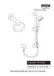
AD JU ST L B A E R AN G E MIRA LOGIC SHOWER FITTINGS Installation & User Guide These instructions are to be left with the user 1 CONTENTS Introduction ............................................................................................. 3 Important Safety Information ................................................................. 4 Pack Contents Checklist ......................................................................... 5 Mira Logic ev and biv Shower Fittings .................................................. 5 Mira Logic biv Shower Right Angle Connector Fittings Pack ................ 6 Mira Logic bir Shower Fittings .............................................................. 6 Dimensions ............................................................................................. 7 Mira Logic ev and biv Shower Fittings .................................................. 7 Mira Logic bir Shower Fittings .............................................................. 7 Specifications .......................................................................................... 8 Installation Requirements ...................................................................... 9 Installation ............................................................................................. 10 Mira Logic Exposed Variable Shower Fittings (ev) ............................. 10 Handset Installation ........................................................................... 12 Soap Dish Installation ........................................................................ 12 Mira Logic Built-in Variable Shower Fittings (biv) ................................ 13 Mira Logic Built-in Rigid Shower Fittings (bir) ..................................... 17 Operation ............................................................................................... 21 Changing Spray Settings ................................................................... 21 Clamp Bracket Adjustment (ev and biv shower fittings only) .............. 22 Shower Head Adjustment (bir shower fittings only) ............................. 22 Fault Diagnosis ..................................................................................... 23 Maintenance .......................................................................................... 24 Cleaning ............................................................................................. 24 High Capacity Nozzle Ring Installation ............................................... 25 Spares .................................................................................................... 26 Mira Logic ev and biv Spares List ...................................................... 26 Mira Logic ev and biv Spares Diagram ............................................... 27 Mira Logic bir Spares List .................................................................. 28 Mira Logic bir Spares Diagram ........................................................... 28 Accessories ........................................................................................... 29 Notes ...................................................................................................... 30 Customer Service .................................................................... Back Page 2 INTRODUCTION Thank you for purchasing a quality Mira product. To enjoy the full potential of your new product, please take time to read this guide thoroughly, having done so, keep it handy for future reference. Mira Logic Adjustable Shower Fittings This Installation and User Guide covers the following products: Mira Logic Exposed Variable Shower Fittings (ev) An adjustable spray handset with four different spray actions (start, soothe, force and eco*), supplied complete with flexible hose, clamp bracket assembly, slide bar, supports, hose retaining ring/gel holder and wall mounted soap dish. Available in chrome, satin/chrome and white/gold finish. Mira Logic Built-in Variable Shower Fittings (biv) Offering the same features as the Logic ev but also includes a right angle connector (RAC). Suitable for connection to concealed pipework supplies. Available in chrome, white, satin/chrome and gold finish. Mira Logic Built-in Rigid Shower Fittings (bir) An adjustable spray built-in shower head with four different spray actions (start, soothe, force and eco*). Suitable for connection to concealed pipework supplies only. Available in white and chrome finish. * The eco setting reduces the water flow on the start mode to give better economical use of water, whilst still giving an adequate shower performance. This setting performs best with most gravity, pumped, and mains pressure unvented systems. On electric showers and some combination boiler systems the economy setting will have no effect, and will give the same spray action as the start setting. If you experience any difficulty with the installation or operation of your new shower fittings, then please refer to "Fault Diagnosis", before contacting Kohler Mira Limited. Our telephone and fax numbers can be found on the back cover of this guide. 3 IMPORTANT SAFETY INFORMATION Warning! 1. Products manufactured by us are safe and without risk provided they are installed, used and maintained in good working order in accordance with our instructions and recommendations. Caution! 1. Read all of these instructions. 2. Retain this guide for later use. 3. Pass on this guide in the event of change of ownership of the installation site. 4. Follow all warnings, cautions and instructions contained in this guide. 5. Anyone who may have difficulty understanding or operating the controls of any shower should be attended whilst showering. Particular consideration should be given to the young, the elderly, the infirm, or anyone inexperienced in the correct operation of the controls. 6. When this product has reached the end of its serviceable life, it should be disposed of in a safe manner, in accordance with current local authority recycling, or waste disposal policy. 4 PACK CONTENTS CHECKLIST 9 Tick the appropriate boxes to familiarize yourself with the part names and to confirm that the parts are included. Mira Logic ev and biv Shower Fittings 2 x Slide Bar End Supports 2 x Wall Plugs 2 x Fixing Screws 1 x Applicator 2 x Slide Bar End Caps 1 x Handset 1 x Clamp Bracket Assembly 1 x Slide Bar 2 x Hose Seals 1 x 1.25 m Flexible Hose 1 x Hose Retaining Ring 1 x Soap Dish 2 x Soap Dish Wall Plugs Documentation 1 x Installation and User Guide 1 x Guarantee Card 1 x Soap Dish Wall Bracket 5 2 x Soap Dish Fixing Screws Mira Logic biv Shower Right Angle Connector Fittings Pack 1 x Wallplate 2 x Wall Plugs 1 x Backplate 1 x Olive 1 x Backplate Nut 2 x Wallplate Screws 1 x Elbow 2 x Backplate Screws 2 x ‘O’ Seals 1 x Shroud Mira Logic bir Shower Fittings 4 x Mounting Plate Screws 1 x Mounting Plate 4 x Wall Plugs 1 x Backplate 1 x Top Cover 4 x BIR Screws 1 x BIR Assembly 1 x Olive 2 x Backplate Screws 1 x Backplate Nut 1 x ‘O’ Seal Documentation 1 x Installation and User Guide 1 x Guarantee Card 4 x Cover Screws 1 x Bottom Cover 6 DIMENSIONS Mira Logic ev and biv Shower Fittings 344 mm Max. 659 mm 156 mm 44 mm 109 mm Mira Logic bir Shower Fittings 20° 20° 212 mm Max. 20° 7 20° SPECIFICATIONS Minimum maintained pressure: with low capacity nozzle ring fitted (as supplied): 0.1 bar with high capacity nozzle ring fitted: 0.2 bar Maximum maintained pressure: 5.0 bar Warning! Exceeding the stated maximum maintained pressure could result in excessive spray forces and possible damage to the product. These are the typical flow performance graphs for the Mira Logic adjustable shower fittings only. There will be an additional pressure loss through the shower control. Pressure loss = Pressure difference between the inlet and outlet of the fitting. Flow Rate (litres/minute) With low capacity nozzle ring fitted 30 28 26 24 22 20 18 16 14 12 10 8 6 4 2 0 Start Eco Force Soothe 0 0.2 0.4 0.6 0.8 1.0 1.2 1.4 Pressure Loss (bar) 1.6 1.8 2.0 1.8 2.0 Flow Rate (litres/minute) With high capacity nozzle ring fitted 30 28 26 24 22 20 18 16 14 12 10 8 6 4 2 0 Soothe Start Eco Force 0 0.2 0.4 0.6 0.8 1.0 1.2 1.4 Pressure Loss (bar) 8 1.6 INSTALLATION REQUIREMENTS Installation must be carried out in accordance with these instructions, and must be conducted by designated, qualified and competent personnel. 1. The hose retaining ring supplied must be used to stop the handset from dropping below the spill-over level of the bath or shower tray. This will prevent water supply contamination due to backsiphonage. 2. Installations must comply with UK Water Regulations/ Bye-laws (Scotland), and Building and Plumbing Regulations in force at the time of installation. 3. When installing the shower fittings in a cubicle, position with the spray pointing across rather than toward the opening of the cubicle. 4. When installing the shower fittings over a bath, position with the spray pointing down the centre line of the bath. 5. Avoid layouts where the shower hose will be sharply kinked. This may reduce the life of the hose. 6. Do not fit any form of flow control in the shower outlet. 7. Do not use excessive force when making connections. 8. Do not install the fittings in a position where it could become frozen. 9. The minimum pressure required for a satisfactory spray pattern to form, at the handset or spray head, is 0.1 bar. For a gravity fed shower installation the minimum head of water required, to accommodate the pressure loss in the pipes and shower control of a typical installation, is 1.0 metre. For a pump installation the minimum acceptable vertical distance between the base of the cold water storage cistern and the shower head to operate the pump’s flow switches, is typically 0.6 m (600 mm). High and Low Capacity Nozzle Rings 1. All shower fittings are supplied with low capacity nozzle rings fitted as standard to the handset or shower head. High capacity nozzle rings, with larger spray holes, are also included in the fittings pack. The low capacity nozzle rings will be suitable for low pressure installations. However for high pressure installations the spray force may be too powerful for comfortable showering. In such situations it is recommended the high capacity nozzle rings are fitted. Refer to the section: High Capacity Nozzle Ring Installation for fitting instructions. 2. For gas water heaters which require a higher flow rate to operate correctly, it is recommended the high capacity nozzle rings are fitted. 9 INSTALLATION Note! For dry lined, stud partition, shower cubicle or laminated panel walls the installer may wish to obtain alternative proprietary cavity fixings. Use of these alternative fixings is beyond the scope of this guide. Important! If the Logic slide bar replaces an existing Mira slide bar make sure that the position of the shower control and the shower fittings provide a minimum of 25 mm between the handset and bath/tray spill-over level. This is necessary to prevent back-siphonage. If this is not possible then the new slide bar will have to be repositioned. Mira Logic Exposed Variable Shower Fittings (ev) Read the section: Installation Requirements before proceeding with the installation. The slide bar should be positioned to one side of the shower control at a convenient height for all the family. It should be positioned so that the handset discharges down the centre line of the bath, or across the opening of the shower cubicle. The handset should be directed away from the shower control. 1. 2. 3. 4. Decide on a suitable position for the slide bar avoiding buried cables and pipes. Make sure that when the hose retaining ring is placed on the lowest position on the slide bar there is a minimum of 25 mm between the handset and bath/tray spill-over level. This is necessary to prevent backsiphonage. Important! The slide bar has been supplied with an applicator fitted to one end (refer to illustration) to assist the assembly of the slide bar through the clamp bracket. With the clamp bracket button FULLY depressed carefully ease the slide bar through the hole in the clamp bracket. Take care not to dislodge the constant friction mechanism or the friction pad. Release the clamp bracket button. Remove the applicator from the slide bar and store in a safe place for future use. Slide the hose retaining ring onto the slide bar below the clamp bracket. 10 Hose Retaining Ring 25 mm Minimum Spill-over level Clamp Bracket Constant Friction Mechanism and Friction Pad Applicator Slide Bar 5. Make sure that the slots in the slide bar are aligned with the lugs in the support and fit the two slide bar supports to the ends of the slide bar. Make sure that each support is pushed firmly home. Note! If replacing an existing Mira Slide Bar proceed to instruction 8. 6. Using the assembled slide bar and supports as a template, mark the position of the two fixing holes using the centre slot. Warning! Make sure that there are no buried cables or pipes in the wall before drilling. 7. Drill the two 8 mm holes for the fixing screws and insert the wall plugs supplied. (Alternatively use proprietary cavity fixings for dry lined, stud partition, shower cubicle or laminated panel walls). 8. Fix the bottom slide bar support to the wall using the screw provided. Make sure that the screw is fully tightened. 9. Loosely screw the top slide bar support to the wall. Press firmly down on the top slide bar support and, while continuing to apply force, fully tighten the screw. 10. Fit the end caps to the slide bar supports. 11. Check the slide bar cannot be rotated or vertically moved. If there is movement remove the slide bar assembly from the wall. Check the slide bar support lugs are properly engaged with the slots in the slide bar and the supports are pushed fully onto the slide bar ends. Refit the slide bar assembly. 12. Refer to sections: Handset Installation and Soap Dish Installation to complete the fittings installation. 11 Wall Plug Top Slide Bar Support Fixing Screw End Cap Slide Bar Clamp Bracket Assembly Hose Retaining Ring Slide Bar Support Lug Bottom Slide Bar Support End Cap Handset Installation 1. 2. 3. Caution! Do not overtighten the hose. Screw the hose onto the outlet of the shower control (Make sure that the hose washer is fitted). Pass the flexible hose through the hose retaining ring and screw the remaining end of the hose onto the handset (Make sure that the hose washer is fitted). Place the handset in the clamp bracket assembly. Handset Hose Washer Clamp Bracket Assembly Hose Retaining Ring Soap Dish Installation 1. 2. 3. 4. 5. 6. Decide on a suitable position for the soap dish, avoiding any buried cables and pipes. Place the wall bracket on the wall and mark the position of the fixing holes. Warning! Make sure that there are no buried cables or pipes in the wall before drilling. Drill the two 8.0 mm fixing holes for the soap dish at 35 mm centres, and insert the wall plugs supplied. Screw the wall bracket to the wall. Clip the soap dish onto the wall bracket. This completes the installation of the Mira Logic adjustable shower fittings. 12 35 mm Soap Dish Wall Plug Wall Bracket Fixing Screw Mira Logic Built-in Variable Shower Fittings (biv) Read the section: Installation Requirements before proceeding with the installation. The slide bar should be positioned to one side of the shower control at a convenient height for all the family. It should be positioned so that the handset discharges down the centre line of the bath, or across the opening of the shower cubicle. The handset should be directed away from the shower control. 15 mm Copper Pipe Solid and Dry-lined Wall Installation 1. The 15 mm copper pipework from the outlet of the shower control must be vertical or horizontal, and not at an angle, so that it does not interfere with the installation screws. Shower Control 21–23 mm 2. 3. The 15 mm copper pipework must protrude through the finished wall surface by 21–23 mm. Note! If it is necessary to trim the pipe to length, remove any burrs before proceeding. 15 mm Copper Pipe Loosely screw the backplate to the wallplate, using the two backplate screws provided. Backplate Wallplate 4. Place the backplate/wallplate assembly over the copper pipe with the arrow pointing up. The screw holes should be at 40° to the horizontal. Backplate Screws Wallplate Fixing Holes Arrow 5. Mark the positions of the two wallplate fixing holes. 13 6. 7. 8. 9. 10. 11. 12. 13. 14. 15. 16. 17. 18. 19. Remove the backplate/wallplate assembly from the wall. Separate the backplate and the wallplate. Drill the two 6 mm wallplate holes. If necessary, make a recess 6 mm deep to accept the wallplate. Fit the two wall plugs supplied. Fit the wallplate to the wall with the two wallplate screws supplied. Temporarily fit the two backplate screws into the wallplate. This will prevent the fixing holes from becoming blocked with plaster or grout. Finish the surface of the wall as required. Remove the two backplate screws from the wall. Place the backplate over the copper pipe with the arrow facing up and tighten the two backplate screws. Make sure that the foam seal abuts the finished wall surface. Check that the ‘O’ seal is fitted inside the backplate nut. Fit the olive and the backplate nut over the copper pipe and tighten the nut. Check that the second ‘O’ seal is fitted to the outside of the backplate nut. Press the elbow onto the backplate, make sure that the clips on the elbow engage with the backplate. Press the shroud over the elbow, make sure that it engages with the lugs on the backplate. Fit the slide bar, handset and soap dish refer to section: Mira Logic Exposed Variable Shower Fittings (ev). 14 6 mm Backplate Screws Fixing Holes Copper Pipe Backplate Arrow Backplate Screws Olive ‘O’ Seal (Inside) ‘O’ Seal (Outside) Clips Backplate Nut Elbow Shroud Shower Cubicle, Laminated Panel or Stud Partition Wall Installation 1. 2. 3. 4. 5. 6. 7. 8. 9. The 15 mm copper pipework from the outlet of the shower control must be vertical or horizontal, and not at an angle, so that it does not interfere with the installation screws. Drill a 25 mm hole in the wall for the copper pipework. Feed the copper pipework through the wallplate and then through the hole in the wall. The 15 mm copper pipework must protrude through the wall by 21-23 mm. Note! If it is necessary to trim the pipe to length, remove any burrs before proceeding. Place the backplate over the copper pipe with the arrow pointing up. The screw holes should be at 40° to the horizontal. Mark the positions of the two backplate fixing holes. Remove the backplate from the wall. Drill the two 5.5 mm backplate holes. Place the backplate over the copper pipe with the arrow facing up. Hold the wallplate in position behind the wall. Insert the two backplate screws through the holes in the wall and fit them to the wallplate. Ensure that the foam seal abuts the finished wall surface. 15 15 mm Copper Pipe Shower Control Wallplate 21–23 mm 15 mm Copper Pipe Panel Finished Wall Surface Backplate Fixing Holes Backplate Arrow Copper Pipe Foam Seal Backplate Arrow Backplate Screws 10. Check that the ‘O’ seal is fitted inside the backplate nut. Fit the olive and the backplate nut over the copper pipe and tighten the nut. Olive ‘O’ Seal (Inside) ‘O’ Seal (Outside) 11. Check that the second ‘O’ seal is fitted to the outside of the backplate nut. Press the elbow onto the backplate, make sure that the clips on the elbow engage with the backplate. Clips Backplate Nut Elbow 12. Press the shroud over the elbow, make sure that it engages with the lugs on the backplate. Shroud 13. Fit the slide bar, handset and soap dish refer to section: Mira Logic Exposed Variable Shower Fittings (ev). 16 Mira Logic Built-in Rigid Shower Fittings (bir) Read the section: Installation Requirements before proceeding with the installation. The shower head should be positioned to one side of the shower control at a convenient height for all the family. It should be positioned so that the spray discharges down the centre line of the bath, or across the opening of the shower cubicle. The shower head should be directed away from the shower control. Solid and Dry-lined Wall Installation 1. The 15 mm copper pipework from the outlet of the shower control must be vertical so that it does not interfere with the installation screws. 15 mm Copper Pipe Shower Control 2. The 15 mm copper pipework must protrude through the finished wall surface by 21–23 mm. Note! If it is necessary to trim the pipe to length, remove any burrs before proceeding. 3. Loosely screw the backplate to the mounting plate using the two backplate screws provided. 4. Place the mounting plate/backplate assembly over the copper pipe. 23–25 mm 15 mm Copper Pipe Mounting Plate 5. Mark the position of the mounting plate and the fixing holes on the wall surface. Backplate Backplate Screws 17 6. Remove the mounting plate/backplate assembly from the wall. 7. Separate the backplate and the mounting plate. 8. Drill the four mounting plate holes and fit the wall plugs supplied. 9. If necessary, make a recess 6 mm deep to accept the mounting plate. 6 mm Mounting Plate Backplate Screws 10. Fit the mounting plate to the wall with the four mounting plate screws supplied. The two threaded holes must be horizontal. 11. Temporarily fit the two backplate screws into the mounting plate. This will prevent the fixing holes from becoming blocked with plaster or grout. Backplate Backplate Screws 12. Finish the surface of the wall as required. 13. Remove the two backplate screws from the wall. 14. Fix the backplate to the wall using the two backplate screws. 15. Fit the olive over the copper pipe and tighten the backplate nut into position. Olive Copper Pipe Backplate Nut 18 16. Ensure that the ‘O’ seal is fitted on the backplate nut. Push the BIR assembly over the backplate nut onto the backplate. 17. Fix the BIR assembly to the backplate using the four cover screws provided. Note! If necessary, a 9 l/min flow regulator can be fitted in the BIR assembly with an adaptor – contact Customer Services. Backplate ‘O’ Seal BIR Assembly Cover Screws 18. Fix the upper shroud to the BIR assembly using the four self-tapping screws provided. Upper Shroud 19. Snap the lower shroud into position. 21. Install the soap dish, refer to section: Soap Dish Installation. Self-tapping Screws Lower Shroud 19 Shower Cubicle, Laminated Panel, or Stud Partition Wall Installation 15 mm Copper Pipe 1. The 15 mm copper pipework from the outlet of the shower control must be vertical so that it does not interfere with the installation screws. 2. Cut a 25 mm hole in the panel. 3. Cut two 5.5 mm holes at 48 mm centres in the panel. 4. Place the mounting plate behind the panel, and feed the copper pipe through the mounting plate and the panel. Make sure that the pipe protrudes 22–25 mm from the wall. Note! If it is necessary to trim the pipe to length, remove any burrs before proceeding. Shower Control 25 mm 5.5 mm Wallplate 5. 5.5 mm 48 mm 22–25 mm Holding the mounting plate in position behind the panel, fix the backplate to the mounting plate, through the panel, with the two backplate screws. 15 mm Copper Pipe 6. Complete the installation following steps 15 to 21 of the Mira Logic bir – Built-in Rigid Shower Fittings: Solid and Dry-lined Wall Installation section. Panel Finished Wall Surface Mounting Plate Backplate Panel Backplate Screws 20 OPERATION Changing Spray Settings The handset has four different spray settings (Eco, start, soothe and force). 1. Eco Setting Turn the spray plate fully clockwise. Water will flow from the outer set of holes and the flow rate will be reduced. This setting performs best with most gravity, pumped, and mains pressure unvented systems. On electric showers and some combination boiler systems the economy setting will have no effect, and will give the same spray action as the start setting. 2. Start Turn the spray plate anticlockwise until it 'clicks' (one click from economy setting). Water will flow from the outer set of holes. 3. Soothe Turn the spray plate anticlockwise until it 'clicks' (two clicks from economy setting). Water will flow from the large diameter holes. 4. Force Turn the spray plate anticlockwise until it 'clicks' (three clicks from economy setting). Water will flow from the inner set of holes. 21 Clamp Bracket Adjustment (ev and biv shower fittings only) Release Button 1. Depress the release button and slide the clamp bracket assembly to the required position. Clamp Bracket Assembly 2. Move the handset to the required angle. A friction mechanism within the clamp bracket assembly will hold the handset at the desired angle. Shower Head Adjustment (bir shower fittings only) 1. Move the spray head to the required position. The spray head is adjustable in both the horizontal and vertical directions. 22 FAULT DIAGNOSIS The trouble shooting information tabled below gives details on what you can do as a user, should you encounter difficulties with the shower fittings whilst operating the shower. Before replacing any parts make sure that the underlying cause of the malfunction has been resolved. Malfunction Cause No flow or low flow Spray plate blocked. rate from shower fittings. Hose blocked or twisted. Remedy Refer to section: Maintenance, Cleaning. Clear blockage or release twist in hose or renew hose. Partially closed stop or Open valve. servicing valve in supply pipe work to the shower control. Head of water below minimum Raise cistern or fit Mira pump. required. Problem with shower control. Refer to the shower control Installation and User Guide. Drip from spray plate A small amount of water may This is quite normal. Changing assembly in handset. be retained in the shower the angle of the shower fitting fitting after the shower control may vary the draining time. has been turned off. This may drain over a few minutes. Problem with shower control. Refer to the shower control Installation and User Guide. Shower temperature Adjusting the spray action changes when spray changes the flow of water. action is adjusted. This may affect some shower controls and plumbing installations. The spray force is High pressure uncomfortably strong. installation. 23 To minimise the effect make sure that the spray plate is clean. Refer to section: Maintenance, Cleaning. If the malfunction persists refer to the shower control Installation and User Guide. shower Fit high-capacity nozzle rings or a 9 l/min flow regulator. MAINTENANCE Cleaning Many household cleaners contain abrasives and chemical substances, and should not be used for cleaning plated or plastic fittings. These finishes should be cleaned with a mild washing up detergent or soap solution, and then wiped dry using a soft cloth. Spray Plate Assembly - External 1. Use your thumb or a soft cloth to wipe any limescale from the soft rubber nozzles and the front face of the spray plate assembly. Spray Plate Assembly - Internal 1. Remove the spray plate assembly. Refer to section: Maintenance, High Capacity Nozzle Ring Installation. 2. Clean all the components with a stiff brush. If necessary use a plastic kettle descalent in accordance with the manufacturer's instructions. Flush thoroughly with water before the shower is used. 3. If necessary replace the 'O' seals. Refer to section: Spare Parts. 4. Refit the components in reverse order. Make sure that the 'O' seals and the inner and outer nozzle retaining rings are fitted correctly. Refer to section: Maintenance, High Capacity Nozzle Ring Installation. 24 Handset Body Assembly Outer Nozzle Ring Retainer 'O' Seals Inner Nozzle Ring Retainer Spray Plate Assembly Adjuster Ring High Capacity Nozzle Ring Installation 1. Turn the adjuster anticlockwise. ring fully 2. Unclip and remove the adjuster ring. 3. Unscrew the spray plate assembly in an anticlockwise direction. The ‘O’ seals will provide some resistance. Inner Nozzle Retaining Ring 4. Remove the inner and outer nozzle retaining rings. Spray Plate Assembly 5. Replace the inner and outer nozzle rings with the high capacity versions supplied. 6. Ensure that the four ‘O’ seals are correctly fitted. Outer Nozzle Ring 7. Fit the inner nozzle retaining ring on the spray plate assembly. Inner Nozzle Ring 8. Fit the inner nozzle retaining ring on the spray plate assembly. 9. Turn the flow divertor fully clockwise. Outer Nozzle Retaining Ring Adjuster Ring Spray Plate Assembly 10. Carefully screw the spray plate assembly onto the flow divertor. ‘O’ Seals 11. Align the inner teeth on the adjuster ring with the teeth on the handset flow divertor. Clip the adjuster ring into position. 25 SPARES Mira Logic ev and biv Spares List 450.01 450.02 450.06 450.08 450.10 450.11 450.12 450.13 450.16 450.17 450.18 450.19 450.20 450.21 450.22 450.23 450.24 450.25 450.26 450.27 450.28 450.29 450.30 450.31 450.32 450.33 450.34 450.35 450.36 450.37 450.38 450.39 450.50 632.73 Hose 1.25 m – chrome Hose 1.25 m – white Clamp Bracket Assembly – (for fittings supplied with Mira Event XS / Sport) Service Pack 'O' seals– components identified 'A' Slide Bar – white Hose Retaining Ring – white Soap Dish Pack – white Adjuster Ring – white Clamp Bracket Assembly – white Slide Bar Wall Fixing Pack– components identified 'B' Hose 1.25 m – gold Adjuster Ring – chrome Right Angled Connector Mounting Pack – components identified 'C' Right Angled Connector Shroud – white Right Angled Connector Shroud – chrome Right Angled Connector Shroud – gold Clamp Bracket Assembly – chrome Clamp Bracket Assembly – satin chrome Slide Bar Support Assembly – white – components identified 'D' Slide Bar Support Assembly – chrome – components identified 'D' Slide Bar – chrome Slide Bar – gold Hose Retaining Ring – chrome Hose Retaining Ring – satin chrome Soap Dish Pack – chrome Soap Dish Pack – gold Adjustable Handset Assembly – white Adjustable Handset Assembly – chrome LC Spray Plate Pack – for white & white/gold fittings HC Spray Plate Pack – for white & white/gold fittings LC Spray Plate Pack – for chrome & satin chrome fittings HC Spray Plate Pack – for chrome & satin chrome fittings Slide Bar Support Assembly – gold – components identified 'D' Hose Washer 26 Mira Logic ev and biv Spares Diagram B 450.10 450.28 450.29 450.34 450.35 D C 450.36 450.37 450.38 450.39 450.21 450.22 450.23 450.06 450.24 450.25 450.16 C 632.73 450.01 450.02 450.18 D B 27 A 450.13 450.19 450.11 450.30 450.31 450.12 450.32 450.33 Mira Logic bir Spares List 450.08 450.12 450.13 450.19 450.32 450.36 450.37 450.38 450.39 450.41 450.42 450.43 Service Pack 'O' seals – components identified 'A' Soap Dish Pack – white Adjuster Ring – white Adjuster Ring – chrome Soap Dish Pack – chrome LC Spray Plate Pack – white HC Spray Plate Pack – white LC Spray Plate Pack – chrome HC Spray Plate Pack – chrome bir Assembly – white bir Assembly – chrome bir Mounting Pack (Consisting of Back Plate Nut, 'O' Seal, Olive, Back Plate, Wallplate, 2 M5 x 40 Screws and 4 M4 x 12 Screws) Mira Logic bir Spares Diagram 450.41 450.42 450.43 450.12 450.32 450.36 450.37 450.38 450.39 A 450.13 450.19 28 ACCESSORIES DCV-H: An outlet double check valve, designed to prevent the backflow or backsiphonage of potentially contaminated water, through shower controls which are fitted with a flexible hose as part of the outlet shower fitting. The inclusion of the Mira DCV-H will increase the required supply pressure typically by 0.1 bar. Available as an optional accessory from Customer Services. DCV-H Outlet Double Check Valve (Part no 110.55) 9 litre/minute Flow Regulator: Designed to limit the flow rate for the Mira Logic fittings in high pressure installations. Contact Customer Services for the flow regulator options for bir fittings. 9 Litre/minute Flow Regulator (Part no. 146.84) 29 NOTES 30 NOTES 31 CUSTOMER SERVICE Guarantee of Quality Spare Parts Mira Showers guarantee your product against any defect in materials or workmanship for the period shown in the Guarantee Registration Document included with your shower. Alternatively, to confirm the applicable guarantee period please contact Customer Services. To validate the guarantee, please return your completed registration card. Within the guarantee period we will resolve defects, free of charge, by repairing or replacing parts or modules as we may choose. To be free of charge, service work must only be undertaken by Mira Showers or our approved agents in Northern Ireland and Republic of Ireland. Service under this guarantee does not affect the expiry date. The guarantee on any exchanged parts or product ends when the normal product guarantee period expires. Not covered by this guarantee: Damage or defects arising from incorrect installation, improper use or lack of maintenance, including build-up of limescale. Damage or defects if the product is taken apart, repaired or modified by any person not authorised by Mira Showers or our approved agents. This guarantee is in addition to your statutory and other legal rights. We maintain an extensive stock of spares, and aim to have functional parts available for ten years from the date of final manufacture of the product. Spares can be purchased from approved stockists or merchants (locations on request) or direct from Customer Services. Spares direct will normally be despatched within two working days. Payment can be made by Visa or Mastercard at the time of ordering. Should payment by cheque be preferred a pro-forma invoice will be sent. Note! In the interests of safety, spares requiring exposure to mains voltages can only be sent to competent persons. Before using your shower Please take the time to read and understand the operating and safety instructions detailed in this manual. What to do if something goes wrong If when you first use your shower it doesn’t function correctly, first contact your installer to check that installation and commissioning are satisfactory and in accordance with the instructions in this manual. We are on-hand to offer you or your installer any advice you may need. Should this not resolve the difficulty, simply contact our Customer Services who will give every assistance, and if necessary arrange for our service engineer to visit. If later the performance of your shower declines, consult this manual to see whether simple home maintenance is required. Please call our Customer Services to talk the difficulty through, request service under guarantee if applicable, or take advantage of our comprehensive AfterSales service. As part of our quality and training programme calls may be recorded or monitored. Our Customer Services Team is comprehensively trained to provide every assistance you may need: help and advice, spare parts or a service visit. Service Our Service Force is available to provide a quality service at a reasonable cost. You will have the assurance of a Mira trained engineer/agent, genuine Mira spares – and a 12 month guarantee on the repair. Payment should be made directly to the Service Engineer/ Agent, using Visa, Mastercard or a cheque supported by a banker’s card. To contact us England, Scotland & Wales Mira Showers Customer Services Telephone: 0870 241 0888 8:30 am to 5:00 pm Working days (4:30 pm Friday) 8:30 am to 12.30 pm Saturday E-mail: [email protected] Fax: 01242 282595 By Post: Cromwell Road Cheltenham Gloucestershire GL52 5EP Northern Ireland Wm H Leech & Son Ltd Telephone: 028 9044 9257 – Mon to Fri 9 am-5pm Fax: 028 9044 9234 – 24 hours Post: Maryland Industrial Estate Ballygowan Road Moneyreagh, Co Down BT23 6BL Republic of Ireland Modern Plant Ltd Telephone: 01 4591344 – Mon to Fri 9am to 5pm Fax: Dublin 01 4592329 – 24 hours Post: Otter House Naas Road Clondalkin Dublin 22 Mira Showers Mira is a registered trade mark of Kohler Mira Limited. Kohler Mira Ltd The company reserves the right to alter Cromwell Road, product specifications without notice. Cheltenham GL52 5EP. www.mirashowers.com P3859/3 32 © Kohler Mira Limited, July 2005