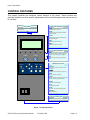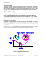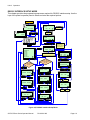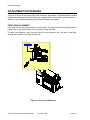
1
GT408/412/424e
Printer
OPERATOR MANUAL
PN 9001138C
Be sure to ask your SATO representatives about our
maintenance contracts to ensure peace of mind during your
usage of SATO products.
For SATO office locations worldwide, visit ww.satoworldwide.com
Copyrights
The contents of this document are proprietary information of SATO Corporation and/or its subsidiaries in
Japan, the U.S and other countries. No part of this document may be reproduced, copied, translated or
incorporated in any other material in any form or by any means, whether manual, graphic, electronic,
mechanical or otherwise, without the prior written consent of SATO Corporation.
Limitation of Liability
SATO Corporation and/or its subsidiaries in Japan, the U.S and other countries make no representations or
warranties of any kind regarding this material, including, but not limited to, implied warranties of
merchantability and fitness for a particular purpose. SATO Corporation shall not be held responsible for errors
contained herein or any omissions from this material or for any damages, whether direct, indirect, incidental or
consequential, in connection with the furnishing, distribution, performance or use of this material.
SATO Corporation reserves the right to make changes and/or improvements in this product and document
without notice at any time.
Trademarks
SATO is a registered trademark of SATO Corporation and/or its subsidiaries in Japan, the U.S and other
countries.
© Copyright SATO Corporation.
All rights reserved.
TABLE OF CONTENTS
INTRODUCTION
About This Manual
General Description
Control Features
1-2
1-3
1-4
TECHNICAL DATA
Physical Characteristics
Power
Enviromental
Processing
Command
Interface Modules
Print
Media
Ribbon
Sensing
Character Font Capabilities
Barcode Capabilities
Regulatory
2-2
2-2
2-2
2-2
2-2
2-2
2-3
2-3
2-3
2-3
2-4
2-5
2-5
INSTALLATION
Unpacking & Parts Identification
Printer Installation
Site Location
Cable Connection
Media Selection
Media & Ribbon Loading
Interface Selection
RS232C Serial Interface
IEEE1284 Parallel Interface
Universal Serial BUS (USB) Adapter
Local Area Network (LAN) Ethernet
802.11B Wireless
Receive Buffer
ACK/NAK Protocol
Accessories Installation
External Signal Connector
Memory Expansion
Interface Upgrade
Label Cutter
Label Peeler
PN 9001138C
3-2
3-2
3-3
3-3
3-4
3-4
3-6
3-6
3-8
3-9
3-9
3-9
3-10
3-10
3-11
3-11
3-12
3-13
3-14
3-14
PRINTER CONFIGURATION
Configuration Modes
Normal Mode
User Mode
Advanced Mode
IEEE1284 Interface Setup Mode
RS232C Interface Setup Mode
Centronics Interface Setup Mode
LAN Interface Setup Mode
USB Interface Setup Mode
Cartidge Mode
SEMBL Mode
Test Print Mode
Download Mode
Hex Dump Mode
Boot Download Mode
Data Save Mode
Default Settings Mode
Print Cancel Mode
Print Darkness Default Mode
Service Mode
Factory Mode
Screen Identification
4-2
4-2
4-3
4-4
4-5
4-6
4-7
4-8
4-9
4-10
4-11
4-12
4-13
4-14
4-15
4-16
4-17
4-18
4-19
4-20
4-21
4-22
TROUBLESHOOTING
Error Signals
Troubleshooting Table
Interface Troubleshooting
Parallel Interface
RS232 Serial Interface
LAN Ethernet Interface
Universal Serial Bus (USB) Interface
Test Print Troubleshooting
Hex Dump Mode
Test Label Printing
Sensor Locations
5-2
5-7
5-9
5-9
5-9
5-10
5-10
5-11
5-11
5-12
5-14
MAINTENANCE
Cleaning Procedures
Replacement Procedures
Print Head
Platen Roller
Adjustment Procedures
Print Head Alignment
Print Head Pressure
Print Head Balance
Ribbon Guide
Label Sensor Positioning
Potentiometer Adjustments
6-2
6-3
6-3
6-4
6-6
6-6
6-7
6-8
6-9
6-10
6-11
PN 9001138C
INTRODUCTION
•
•
•
SATO GT4xxe Series Operator Manual
About This Manual
General Description
Control Features
PN 9001138C
Page 1-1
Unit 1: Introduction
ABOUT THIS MANUAL
This manual is laid out consistent with the product discussed and provides all of the information
required for printer maintenance and repair by SATO approved personnel. For the repair
technician, this manual is intended to compliment, and to be used as an extension of, owner/
operator literature.
This manual also incorporates the use of special information boxes. Examples of these boxes
and the type of information provided in each, are below.
WARNING: PROVIDES INFORMATION THAT, IF UNHEEDED, MAY
RESULT IN PRESONAL INJURY.
CAUTION: PROVIDES INFORMATION THAT, IF UNHEEDED, MAY
RESULT IN EQUIPMENT DAMAGE.
NOTE: Provides helpful hints to assist in performing the tasks at hand.
LCD DISPLAY: Provides the specific display that should be visible on
the LCD at that point.
A comprehensive Table Of Contents provided at the front of this manual facilitates rapid
movement within. The contents identify the different Units, Chapters, and Sections. Each
references the page number of their commencement.
The pages of this manual have embedded headers and footers to assist the user in identifying
his or her exact position within the manual. The header provides the section number followed by
its name. The footer identifies the product on the left, the manual’s part number in the center, and
the page number to the right side of the page.
Page enumeration is two-part with each separated by a hyphen. The first character set
references the Unit and the second identifies the page number. Page numbers begin with the
numeral (1) one at the commencement of a new unit and ascends sequentially.
SATO GT4xxe Series Operator Manual
PN 9001138C
Page 1-2
Unit 1: Introduction
GENERAL DESCRIPTION
The GT4xxe series printer is a high-performance printer capable of printing all popular bar codes
and twelve human-readable fonts; providing an inventory of thouasnds of styles and sizes. Its
heavy metal construction is designed to deliver optimum performance in demanding
environments.
Top Housing Cover
Rear Housing Cover
Left Housing Cover
Memory Card Access
Ribbon Supply Spindle
Ribbon Rewind Spindle
Media Holder
Operator Panel
Power Switch
Media Guide
Side Cover
Platen Roller Assembly
Front Housing Cover
Print Head Assembly
Figure 1-1a, Primary Components
SATO GT4xxe Series Operator Manual
PN 9001138C
Page 1-3
Unit 1: Introduction
CONTROL FEATURES
This chapter identifies the interactive control features of the printer. These functions are
generally defined here. More specific explainations will be found throughout this manual on how
to use them.
LCD Display
LED Indicators
Communicates operational conditions via the use
of icons and text.
POWER
Illuminates when the power on.
ONLINE
Illuminates when communication is available .
Flashes when fails.
STATUS
Flashes when an error occurs. Flashes when
sending/receiving data.
LABEL
Flashes when paper error occurs.
RIBBON
Flashes when ribbon error occurs.
POWER ON LINE
STATUS
LINE
LABEL
Operator Buttons
RIBBON
FEED
Feeds the equivalent of a sheet of paper when
pressed once. Positions paper if misaligned .
FEED
LINE
Starts and stops printing and transmission of
data.
FUNCTION
VOLUME
ENTER
PITCH
Maintenance Panel
CANCEL
OFFSET DARKNESS
FUNCTION
Allows movement through the various menus
and modes.
Permits the movement of the cursor for input.
ENTER
Allows the selection of an option .
CANCEL
Cancels a print job. Allows return to the previous
screen when moving through the menus.
VOLUME
For buzzer volume adjustment.
PITCH
For adjusting print position.
OFFSET
Adjusts cut, peel, and tear-off stop positions.
DARKNESS
Adjusts print density .
Power Switch
Breaks the circuit providing power to the printer.
Figure 1-2, Operator Panel
SATO GT4xxe Series Operator Manual
PN 9001138C
Page 1-4
TECHNICAL DATA
•
•
•
•
•
•
•
•
•
•
•
•
SATO GT4xxe Series Operator Manual
Physical Characteristics
Power
Enviromental
Processing
Print
Media
Ribbon
Sensing
Interface Modules
Character Font Capabilities
Barcode Capabilities
Regulatory Approvals
PN 9001138C
Page 2-1
Unit 2: Technical Data
PHYSICAL CHARACTERISTICS
Width
10.67 Inches (271 mm)
Height
12.00 Inches (305 mm)
Depth
17.90 Inches (455 mm)
Weight
33.07 Pounds (15.0 Kg) standard
POWER
Input Voltage
Power Consumption
100-240 Volts AC +/- 10%, 50/60 Hertz +/-5%
200 Volts/150 Watts Operating, 89 Volts/40 Watts Idle
ENVIRONMENTAL
Operating Temperature
32° to 104°F (0° to 40°C)
Storage Temperature
23° to 140°F (-5° to 60°C)
Storage Humidity
30 to 90% RH Non-Condensing
Operating Humidity
30 to 80% RH Non-Condensing
PROCESSING
CPU
32 Bit RISC
FLash ROM
2 Megabytes
SDRAM
4 Megabytes
Receive Buffer
Extended Memory
2.95 Megabytes
Flash Memory Board (8 Megabytes)
COMMAND
Standard
SATO Barcode Printer Language (SBPL)
Intelligent Command
Optional
SATO Embedded Basic Language (SEMBL)
INTERFACE MODULES
Enhanced Parallel Port
IEEE1284 (ECP Compatible)
Centronics Parallel Port
Centronics
Serial Port
Universal Serial Bus
LAN
Ethernet (Wireless LAN)
Mini LAN
SATO GT4xxe Series Operator Manual
RS232C (9600 to 57,600 bps) Standard
RS422/485 (9600 to 57600 bps) Optional
USB Adapter (12 Mbps)
10BASE-T/100BASE-TX Automatic Switching
10/100 Base T, 802.11B Wireless Wi-Fi
10BASE-T/100BASE-TX Automatic Switching
PN 9001138C
Page 2-2
Unit 2: Technical Data
PRINT
Method
Speed (user selectable)
Direct Thermal / Thermal Transfer
Thermal Transfer: 2, 3, 4, 5, 6, 7, 8, 9, 10, 11, 12 Inches Per Second
Direct Thermal: 2, 3, 4, 5, 6 Inches Per Second
Print Module (dot size)
.0049 Inches (.125 mm)
203 Dots Per Inch (8 dpmm)
305 Dots Per Inch (12 dpmm)
609 Dots Per Inch (24 dpmm)
Resolution
Maximum Print Width
4.10 Inches (104 mm)
Maximum Print Length
GT408 Printer: 98.43 Inches (2500 mm)
GT412 Printer: 59.06 Inches (1500 mm)
GT424 Printer: 15.75 Inches (400 mm)
MEDIA
Roll Media
Roll Paper: 10.43 Inch (265 mm) maximum diameter.
Core Size: 1.5, 3, 4 Inch (38.1, 76.2, 101.6 mm) internal diameter.
Wound: Face In / Face Out. Face Out is for linerless only.
Fan-Fold Media
Maximum folded height: 7.87 Inches (200 mm)
Standard Mode
Tear-Off
Thickness
Media Width: 0.87 to 5.04 Inches (22-128 mm)
Media Length: 0.24 to 5.04 Inches (6-397 mm)
Backing Paper Width: 0.98 to 5.16 Inches (25-131 mm)
Backing Paper Length: 0.35 to 15.75 Inches (9-400 mm)
Media Width: 0.87 to 5.04 Inches (22-128 mm)
Media Pitch: 0.67 to 5.04 Inches (17-397 mm)
Backing Paper Width: 0.98 to 5.16 Inches (25-131 mm)
Backing Paper Length: 0.79 to 15.75 Inches (20-400 mm)
0.002 to 0.010 Inches (0.06 - 0.268 mm)
RIBBON
Minimum:
1.56 Inches (39.5 mm)
Width
Maximum: 1.77, 2.32, 2.99, 3.31, 3.62, 4.02, 4.37, 5.04
(45, 59, 76, 84, 92, 102, 111, 128 mm)
Length
492 yards (450 m) roll.
Wound
Face In / Face Out.
Roll Diameter
3.34 Inches (85 mm)
SENSING
Gap
Adjustable
Reflective Eye-Mark
Adjustable
Label
Adjustable
Continuous Form
SATO GTxxe Series Operator Manual
Sensor not used.
PN 9001138C
Page 2-3
Unit 2: Technical Data
CHARACTER FONT CAPABILITIES
MATRIX FONTS
U
5 dots W x 9 dots H
S
8 dots W x 15 dots H
M
13 dots W x 20 dots H
XU
5 dots W x 9 dots H (Helvetica)
XS
17 dots W x 17 dots H (Univers Condensed Bold)
XM
24 dots W x 24 dots H (Univers Condensed Bold)
OA Font (OCR-A)
OB Font (OCR-B)
AUTO SMOOTHING FONTS
WB
18 dots W x 30 dots H
WL
28 dots W x 52 dots H
XB
48 dots W x 48 dots H (Univers Condensed Bold)
XL
48 dots W x 48 dots H (Sans Serif)
VECTOR FONT
Proportional or Fixed Spacing
Font Size 50 x 50 dots to 999 x 999 dots
Helvetica, 10 Font Variations
AGFA RASTER FONTS
A Font
CG Times, 8 to 72 pt.
B Font
CG Triumvirate, 8 to 72 pt.
DOWNLOADABLE FONTS
Bit Mapped True Type Fonts with Utility Program
CHARACTER CONTROL
Expansion up to 12 x in either the X or Y coordinates.
Character Pitch Control
Line Space Control
Journal Print facility
0, 90, 180, and 270 Degree Rotation
SATO GT4xxe Series Operator Manual
PN 9001138C
Page 2-4
Unit 2: Technical Data
BAR CODE CAPABILTIES
UPC-A/E
CODABAR
Code 39
Code 93
Code 128
Interleaved 2 of 5
Matrix 2 of 5
Bookland
RSS-14
MSI
POSTNET
UCC/EAN 128
Customer Barcode
Linear Bar Codes
QR Code
Data Matrix
Macro BDF
Maxi Code
PDF417
Micro PDF417
Truncated PDF
QR Code
NW-7 (Codabar)
Composite Symbology
Two Dimemsional
Ratios
1:2, 1:3, 2:5, User definable bar widths
Bar Height
4 to 999 dots, User progammable
Rotation
0, 90, 180, and 270 Degrees
Sequential Numbering
Sequential numbering of both numerics and bar codes
Custom Characters
RAM storage for special characters
Expansion Ratio of Character
Graphics
Height: 1-12 times, Width: 1-12 times
Full dot addressable graphics, SATO Hex/Binary, BMP or PCX formats
Form Overlay
Form overlay for high-speed editing of complex formats
REGULATORY
Safety
EN 55022 (Class B), UL (CUL), TUV
Radiant Noise
VCCI (Class B)
AC Line Noise
Over 1000V p-p
Static Electricity
SATO GTxxe Series Operator Manual
IEC (Level 3)
PN 9001138C
Page 2-5
Unit 2: Technical Data
SATO GT4xxe Series Operator Manual
PN 9001138C
Page 2-6
INSTALLATION
•
•
•
•
•
SATO GT4xxe Series Operator Manual
Unpacking
Parts Identification
Printer Installation
Interface Selection
Accessories Installation
PN 9001138C
Page 3-1
Unit 3: Installation
UNPACKING & PARTS IDENTIFICATION
Unpack the printer as directed in the following procedure.
1
Place the shipping container (box) upright on a soid, flat surface.
2
Open the box, remove any loose items and the first layer of packing material.
3
Carefully lift the printer and accessories from the box and place them on a solid flat surface.
4
Remove the plastic covers from the packed items and visually inspect for physical damage.
5
Ensure all components are present as dictated on the Packing List.
6
Report damaged property.
Accessory Box
Printer
Cushion
Shipping Container
Figure 3-1, Unpacking
SATO GT4xxe Series Operator Manual
PN 9001138C
Page 3-2
Unit 3: Installation
PRINTER INSTALLATION
This chapter provides guidance on how to station, connect, and load the printer once unpacked.
Following printer setup, procede to the next chapter for information on interface selection.
SITE LOCATION
•
Stationed on a solid flat surface.
•
Stationed away from hazardous materials.
•
Stationed within operational distance of the host based on interface specifications.
CABLE CONNECTION
The procedure below provides instruction on typical cable connection. The same procedure will
apply to others that are not mentioned, but their connectors are also located behind the rear
housing cover.
1
Press the rear housing ocver catch and remove laterally (Figure 3-2a).
2
Locate and identify the required connectors (Figure 3-2b).
3
Connect the power supply and interface cables to their respective connectors (Figure 3-2c).
4
Replace rear housing cover (Figure 3-2d).
Rear Housing Cover
Interface Connectors
Housing Cover Catch
Power Supply Connector
Figure 3-2b
Figure 3-2a
Rear Housing Cover
Pull Prevention Slot
Figure 3-2d
Figure 3-2c
SATO GT4xxe Series Operator Manual
PN 9001138C
Page 3-3
Unit 3: Installation
MEDIA SELECTION
The size and type of the labels or tags to be printed should have been taken into consideration
before printer purchase. Ideally, the media width will be equal to, or just narrower than, the print
head. Using media that does not cover the print head will allow the platen roller to tread on it and
wear it out. The media edge will also wear a groove in the platen roller affecting print quality.
MEDIA & RIBBON LOADING
There are two general media types that may be loaded and used; rolled and fan-folded. Each of
those types may again be defined by whether their print application is direct thermal or thermal
transfer. Those factors determine how the media is loaded and if ribbon stock is loaded at all.
Thermal transfer media requires the use of ribbon stock for print application. In such a scenario,
it is the ribbon stock (carbon paper) that contains the ink that will be transfered to the media.
Direct thermal media has the ink embedded within and is brought to the surface through heat
penetration by print head contact.
Rolled media of standard diameter is loaded within the printer and suspended by the media
holder. Larger, non-standard rolled media would be suspended outside the printer at its rear and
fed inward. Fan-folded media would also be fed inward from the rear but is stacked as opposed
to suspended.
Refer to Figures 3-3a and 3-3b for proper media routing relative to the type to be used. If that to
be used is direct thermal, ignore the ribbon stock in the figures and do not load that.
Ribbon Roll
Media Holder
Media Guide
Media
Print Assembly
Media Ramp
Label Damper
Figure 3-3a, Rolled Media & Ribbon Loading
SATO GT4xxe Series Operator Manual
PN 9001138C
Page 3-4
Unit 3: Installation
Ribbon Roll
Media Holder
Media Guide
Media
Print Assembly
Media Ramp
Label Damper
Figure 3-3b, Fan-fold Media & Ribbon Loading
SATO GT4xxe Series Operator Manual
PN 9001138C
Page 3-5
Unit 3: Installation
INTERFACE SELECTION
This chapter presents the printer interface types and their specifications. These specifications
include detailed information to assist in the selection of the most appropriate method for the
printer to interface with the host. The four acceptable interface methods are:
•
RS232C Asynchronous Serial
•
IEEE1284 Parallel
•
Universal Serial Bus (USB) Adapter
•
Local Area network (LAN) Ethernet
•
802.11B Wireless
Following the selection of the desired interface, proceed to the following unit for instructions on
how to Configure the printer for that interface type.
WARNING: NEVER CONNECT OR DISCONNECT INTERFACE CABLES
(OR USE A SWITCH BOX) WITH POWER APPLIED TO EITHER THE
HOST OR THE PRINTER. THIS MAY CAUSE DAMAGE TO THE
INTERFACE CIRCUITRY IN THE PRINTER/HOST AND IS NOT COVERED
BY WARRANTY.
NOTE: Some hosts monitor the Request-To-Send (RTS) signal (pin 4 of 25)
to determine if the printer is ready to receive data. Since the printer does not
generate this signal, the RTS line must be held true (high) in order to allow
communication. This can be performed by connecting the RTS pin to the
Clear-To-Send (CTS) signal (pin 5 of 25).
RS232C SERIAL INTERFACE
This High Speed Serial Interface is a Plug-In Interface Module that can be installed in the printer
by the user. The only difference between this interface and the TTL is their signal levels and
cable pinouts.
RS232C SPECIFICATIONS
Asynchronous ASCII
Data Transmission Rate
Data Length
Stop Bit
Parity Bit
Codes Used
Control Codes
Connector
Cable
Signal Levels
SATO GT4xxe Series Operator Manual
Half-duplex communication
Bi-Directional Communication
9600, 19200, 38400, 57600 bps
8 bit (selectable)
1 bit (fixed)
ODD, EVEN, NONE (selectable)
ASC II Character Codes, JIS Kanji Codes
STX (02H), ETX (03H), ACK (06H), NAK (15H)
Special
Special
High = +5V to +12V, Low = -5V to -12V
PN 9001138C
Page 3-6
Unit 3: Installation
RS232C SERIAL INTERFACE SIGNALS
PIN
DIRECTION
1
2
Reference
To Host
3
4
To Printer
To Host
5
To Printer
6
To Printer
7
20
Reference
To Host
SIGNAL DEFINITION
FG (Frame Ground)
TD (Transmit Data) - Data from the printer to the host computer. Sends X-On/
X-Off characters or status data (bi-directional protocols).
RD (Receive Data) - Data to the printer from the host computer.
RTS (Request to Send) - Used with Ready/Busy flow control to indicate an
error condition. RTS is high and remains high unless the print head is open (in
this case, RTS would return to the high state after the print head is closed and
the printer is placed back on-line) or an error condition occurs during printing
(e.g., ribbon out, label out).
CTS (Clear to Send) - When this line is high, the printer assumes that data is
ready to be transmitted. The printer will not receive data when this line is low. If
this line is not being used, it should be tied high (to pin 4).
DSR (Data Set Ready) - When this line is high, the printer will be ready to
receive data. This line must be high before data is transmitted. If this line is not
being used, it should be tied high (to pin 20).
SG (Signal Ground)
DTR (Data Terminally Ready) - This signal applies to Ready/Busy flow control.
The printer is ready to receive data when this pin is high. It goes low when the
printer is off-line, either manually or due to an error condition, and while
printing in the single job buffer mode. It will also go low when the data in the
buffer reaches the buffer near full level.
13
1
25
14
Figure 3-4, Serial Interface Pin Assignments
CABLE REQUIREMENTS
DB9 DB25
HOST
CONNECTION
DB9
PRINTER
1
1
FG (Frame Ground)
Bi-Directional
1
FG (Frame Ground)
2
3
RD (Receive Data)
To Host
2
TD (Transmit Data)
3
2
TD Transmit Data)
To Printer
3
RD (Receive Data)
8
5
CTS (Clear To Send)
To Printer DB9-6
4
RTS (Request to Send)
4
20
DTR (Data Temrinal Ready) To Printer DB9-4
6
DSR (Data Set Ready)
6
6
DSR* (Data Set Ready)
To Host
9
DTR (Data Terminal Ready)
5
7
SG (Signal Ground)
Bi-Directional
7
SG (Signal Ground)
* This connection at the host side of the interface would depend upon the pin that is being used as the
Ready/Busy signal by the driving software. Typically, on a PC, it would be either CTS (pin5) or DSR (pin
6) on a DB-25 connector.
SATO GT4xxe Series Operator Manual
PN 9001138C
Page 3-7
Unit 3: Installation
IEEE1284 PARALLEL INTERFACE
The parallel interface is a plug-in module that can be installed by the user and conforms to
IEEE1284 specifications. It automatically detects the IEEE1284 signals and operates in the high
speed mode. If the IEEE1284 signals are not detected, it will operate in the slower standard
Centronics mode. For this reason, an interface cable and host interface conforming to the
IEEE1284 specification must be present to fully utilize the speed capabilities. This interface also
operates bi-directionally and can report the status of the printer back to the host.
SPECIFICATIONS
Printer Connector
Cable Connector
Cable
Signal Level
Data Stream
AMP 57-40360 DDK (or equivalent)
AMP 57-30360 DDK (or equivalent)
IEEE1284 Parallel, 10 ft. (3 m) or less
High = +2.4V to +5.0V, Low = 0V to -0.4V
<ESC>A . . Job#1 . . <ESC>Z<ESC>A . . Job#n . . <ESC>Z
18
1
36
19
Figure 3-5, Parallel Interface Pin Assignments
IEEE 1284 PARALLEL INTERFACE PIN ASSIGNMENTS
PIN
SIGNAL
DIRECTION
PIN
SIGNAL
1 Strobe
To Printer
2 Data 1
To Printer
3 Data 2
To Printer
4 Data 3
To Printer
5 Data 4
To Printer
6 Data 5
To Printer
7 Data 6
To Printer
8 Data 7
To Printer
9 Data 8
To Printer
10 ACK
To Host
11 Busy
To Host
12 Ptr Error
To Host
13 Select
To Host
14 AutoFD1
To Host
15 Not Used
16 Logic Gnd
17 FG
Frame Gnd
18 +5V (z=24k ohm) To Host
1 Signals required for ieee 1284 mode.
19
20
21
22
23
24
25
26
27
28
29
30
31
32
33
34
35
36
Strobe Return
Data 1 Return
Data 2 Return
Data 3 Return
Data 4 Return
Data 5 Return
Data 6 Return
Data 7 Return
Data 8 Return
ACK Return
Busy Return
PE Return
INIT
Fault
Not Used
Not Used
Not Used
SelectIn1
SATO GT4xxe Series Operator Manual
PN 9001138C
DIRECTION
Reference
Reference
Reference
Reference
Reference
Reference
Reference
Reference
Reference
Reference
Reference
Reference
From Host
To Host
From Host
Page 3-8
Unit 3: Installation
UNIVERSAL SERIAL BUS (USB) ADAPTER
The Universal Serial Bus (USB) interface is a Plug-In Interface Module that can be installed by
the user. It requires a driver (shipped with each printer that has the interface installed) that must
be loaded on your PC and the PC must be configured to support USB peripherals using Windows
98 or above. Details for loading the USB driver are contained in the USB Interface Manual that is
shipped with each printer with a USB Optional interface installed. Up to 127 devices may be
connected to a USB port using powered hubs.
SPECIFICATIONS
Printer Connector
Cable
Host
Power Supply
Power Consumption
USB Type B Plug
10 feet (3 m) maximum
Windows 98 or above with USB Port
BUS Power through cable
+5 V at 80 ma
LOCAL AREA NETWORK (LAN) ETHERNET
A Local Area Network (LAN) interface is an optional Plug-In Interface Module that can be
installed by the user. It requires a driver shipped with each printer that has the interface installed.
The driver that must be loaded on your PC and the PC must be configured to run one of the
supported network protocols using a 10/100BaseT LAN connection. Details for loading the LAN
driver are contained in the LAN Interface Manual that is shipped with each printer with a LAN
Optional interface installed.
SPECIFICATIONS
Connector
Cable
Power Supply
RJ-45 Receptacle
10/100BaseT Category 5
Powered from printer
802.11B WIRELESS
The wireless print server provides easy printer interface with 802.11b Wi-Fi compliant networks
free of wired connections. Each printer is shipped with an integrated driver and interface
installed. The driver must be loaded on your PC and the PC must be configured to run one of the
supported protocols.
802.11B WIRELESS SPECIFICATIONS
Variable Data Rates
Frequency Band
Wired Equivalent Privacy
Sensitivity
Range
Protocols
SATO GT4xxe Series Operator Manual
11, 5.5, 2 and 1 Mbps
2.4 GHz ISM Band
128 bit, 64 bit (compatible with 40bit), none
(typ, AAWGN, 8E-2 PER): -91dBm at 1Mbps, -88dBm at 2 Mdps,
-87dBm at 5.5Mbps, -84dBm at 11Mbps.
100m indoors, 300m outdoors
TCP/IP, IPX/SPX, Direct Mode IPX/IP, DLC/LLC, NetBEUI,
NetBIOS/IP
PN 9001138C
Page 3-9
Unit 3: Installation
RECEIVE BUFFER
The data stream is received from the host to the printer one job at a time. This allows the
software program to maintain control of the job print queue so that it can move a high priority job
in front of ones of lesser importance.
A multiple job buffer allows the printer to continuously receive print jobs while compiling and
printing other jobs at the same time. It acts much like a Print buffer to maximize the performance
of the host and the printer.
The printer receives and prints one job at a time. If a print job exceeds the buffer size,
transmission will be rejected by the printer. Flow control protocols to throttle transmission are not
used. Error conditions that occur during the Print Data transmission will cause the printer to
return a NAK.
ACK/NAK PROTOCOL
Bi-Directional ACK/NAK protocol is used for error control. In a normal transmission sequence
when the transmission is received, the printer will return an ACK (06H) signifying that it was
received without a transmission error. After the transmission command structure has been
analyzed, a status byte is returned to the host. This status byte informs the host of the validity of
the command structure.
If the command structure is error free, the printer proceeds with the print operation. When the
print operation is completed, a Printer Status message is returned to the host. If an error was
detected during the initial transmission sequence, a NAK (15H) will be returned signalling to the
host that the received transmission contained errors and must be resent. If the returned Status
byte indicates a command structure error, the error must then be corrected before the print data
is resent to the printer.
A valid transmission to the printer must be bounded by an STX/ETX pair, with the STX (02H)
signifying the start of the Print Data and ending with an ETX (03H) signifying the end.
SATO GT4xxe Series Operator Manual
PN 9001138C
Page 3-10
Unit 3: Installation
ACCESSORIES INSTALLATION
EXTERNAL SIGNAL CONNECTOR
This connector permits the interface of an external source with the printer for the purpose of
regulating print actiivity to coincide with those external requirements (i.e.: production flow, etc.).
1 Disconnect power supply cord and remove the rear housing cover (1, Figure 3-6).
2
Remove screw (2) and plate (3) as required to expose the EXT port.
3
Remove two screws (4) and withdraw existing board (5) from frame (6) as required.
NOTE: The above step only applies if replacing an exisiting board.
4
Insert external signal board (5) into slot in frame (6) and secure using two screws (4).
5
Connect the interface cord, power cord, and reinstall rear housing covers.
6
5
IEEE1
284 +
3
D
RS BOAR
1
4
2
Figure 3-6, External Signal Connector
SATO GT4xxe Series Operator Manual
PN 9001138C
Page 3-11
Unit 3: Installation
MEMORY EXPANSION
The memory cartridge provides additional storage of user data and graphics. Access to the
memory cartridge port, and its installation, is very simple. The instructions below provide
guidance.
CAUTION: INSTALL THE MEMORY CARTRIDGE PRIOR TO SENDING
RELATIVE COMMANDS OR AN ERROR WILL OCCUR. REMOVE POWER
TO THE PRINTER PRIOR TO INSTALLING THE CARTRIDGE.
1 Disconnect power supply cord.
2
Detach memory cartridge cover (1, Figure 3-7) from center frame (2).
3
Fully insert memory cartridge (3) into its respective port and replace cover (1).
4
Restore power to the printer and send commands.
3
1
2
Figure 3-7, PCMCIA Memory Expansion
SATO GT4xxe Series Operator Manual
PN 9001138C
Page 3-12
Unit 3: Installation
INTERFACE UPGRADE
The printer is typically ordered with a high-speed parallel interface board installed. However,
interface requirements sometimes change and an upgrade is desired. All of the interface boards
are installed within the same slot (middle) located in the rear of the printer with little or no
difference in installation methodology with the exception of the mini-LAN interface (top slot).
Parallel Interface (IEEE1284)
(Optional or Bundled)
Serial Interface (RS232C)
(Optional)
USB Interface
(Optional)
10BaseT/100Base-TX Lan Interface
(Optional)
Wireless LAn 802.11b Interface
(Optioanl)
10BaseT/100Base-TX mini LAN
(Optional(
EXT Connector (External Signal Interface)
(Optional)
1
Remove the rear housing cover (1, Figure 3-8). Disconnect the power and interface cords.
2
Remove screw (2) and plate (3) as required to expose the interface port.
3
Remove two screws (4) and withdraw existing board (5) from frame (6) as required.
4
Insert replacement board (5) into slot in frame (6) and secure using two screws (4).
5
Connect the interface cord, power cord, and reinstall rear housing covers.
3
5
284
IEEE1
D
+ RS BOAR
6
4
2
1
Figure 3-8, Interface Upgrade
SATO GT4xxe Series Operator Manual
PN 9001138C
Page 3-13
Unit 3: Installation
LABEL CUTTER INSTALLATION
The label cutter, when installed, replaces the printer’s lower front housing cover. Its internal
sensor monitors media feed and activates the cut sequence based on user established values.
The cutter assembly is powered through relayed current from the printer’s power supply and
derives its primary intelligence from the main circuit board. The activated cut sequence severs
the printed media from the unprinted media allowing the operator to retrieve and apply at will.
Installation instructions are provided with the purchased product.
LABEL PEELER INSTALLATION
The label peeler, when installed, replaces the printer’s lower front housing cover. As the label is
printed and fed forward, the peel bar separates the printed label from its paper backing and
presents it for application. When the printed label is retrieved by the operator, the printer feeds
the unprinted media back into position for another print sequence. The cycle is again repeated.
Installation instructions are provided with the purchased product.
SATO GT4xxe Series Operator Manual
PN 9001138C
Page 3-14
PRINTER
OPERATION
•
•
SATO GT4xxe Series Operator Manual
Configuration Modes
Operational Adjustments
PN 9001138C
Page 4-1
Unit 4: Operation
CONFIGURATION MODES
This chapter provides an overview of the various configuration modes of the operation menu. All
of the following configuration activities are performed via the use of the operator panel located on
the printer front. However, many settings may also be controlled via software commands. In the
case of conflict between the software and control panel settings, the printer will always use the last
entered valid setting.
NORMAL MODE
When a print job is received, the LCD will display the number of labels to be printed and will
numerically descend as each label is printed.
POWER
ONLINE
CANCEL or
software issued
print stop request
Printing
starts
PAUSE
QTY: 000000
QTY: 000000
LINE
LINE
ENTER +
OFFLINE
000000
ENTER +
for 5 seconds
CANCEL
CANCEL PRINT JOB
YES
NO
Yes / No
CANCEL PRINT JOB
COMPLETED
Refer
to User
Mode flow
chart.
DATA SAVE START
YES
NO
Yes / No
No
COPYING
0
100
DATA SAVE
COMPLETED
ENTER
Refer
to Interface
Mode flow
chart.
Refer
to Cartridge
Mode flow
chart.
Refer
to SEMBL
Mode flow
chart.
Refer
to Advanced
Mode flow
chart.
Refer
to Hex Dump
flow chart.
Figure 4-1, Normal Mode
SATO GT4xxe Series Operator Manual
PN 9001138C
Page 4-2
Unit 4: Operation
USER MODE
This mode allows cofiguration of printing features that are prone to change from job to job. These
are some of the most basic and common adjustments of all of the configuration modes.
POWER
ENTER
ONLINE
QTY: 000000
ENTER
LINE
OFFLINE
000000
Displays
when valid.
ENTER
PASSWORD
0000
Scroll to enter.
Press ENTER.
OFFSET VOLUME
PITCH
+0.00
OFFSET
+0.00
DARKNESS
00
Press FUNCTION
anytime to return to
User Mode.
CANCEL
ENTER
PRINT SPEED
06 IPS
ENTER
Kanji Font Card
Installed?
Yes / No
CANCEL
PRINT DARKNESS
1
2
3
4
5
CANCEL
ENTER
JIS CODE
JIS
SJIS
PITCH OFFSET
+00mm
KANJI FONT
MINCHO
ENTER
CANCEL
GOTHIC
PRINT OFFSET
V:+0000
CHARACTER PITCH
PROPORTIONAL
FIXED
H:+0000
CANCEL
ENTER
ZERO SLASH
YES
ENTER
NO
CANCEL
Figure 4-2, User Mode
SATO GT4xxe Series Operator Manual
PN 9001138C
Page 4-3
Unit 4: Operation
ADVANCED MODE
The Advanced Mode is provided to make basic printer operational adjustments. Typically, once
these adjustments or settings have been made, they will not require additional address unless a
new job is downloaded. The following table identifies the menus of the Advanced Mode and their
purpose.
CANCEL + POWER
HEAD CHECK
Printer
beeps
ENABLE DISABLE
ENTER
Press FUNCTION
anytime to return to
Advanced Mode.
Disable +
ENTER
Enable +
ENTER
HEAD CHECK
NORMAL BARCODE
DARKNESS RANGE
A B C D
E
CANCEL
F
EXTERNAL SIGNAL
ENABLE DISABLE
ENTER
CANCEL
PRINTER TYPE
AUTO SETTING
YES
Disable +
ENTER
Enable +
ENTER
EXTERNAL SIGNAL
TYPE1 TYPE2
TYPE3 TYPE4
NO
ENTER
EXTERNAL REPRINT
CANCEL
ENABLE DISABLE
Only
visible when hardware
is installed and
detected by the
printer.
PRINTER TYPE
ENTER
CONTINUOUS
TEAR OFF
DISPENSER
CUTTER
LINERLESS
CANCEL
CANCEL
AUTO ONLINE
YES
NO
ENTER
CANCEL
Only
visible if the Cutter ,
Dispenser and or
Linerless features are
selected. Only BEFOR or
NONE can be selected
for Linerless
feature.
AUTO ONLINE FEED
AFTER
BEFOR
NONE
YES
ENTER
CANCEL
ENTER
SENSOR TYPE
I-MARK1
GAP
I-MARK2
ON
NO
ENTER
REWINDER
Only
visible if the
Dispenser feature has
been selected and the
Continuous print
operation mode
is active.
ENTER
BACKFEED MOTION
CANCEL
FEED ON ERROR
OFF
CANCEL
YES
ENTER
NO
CANCEL
ENTER
PRINT METHOD
PROTOCOL CODE
TRANSFER DIRECT
STANDARD
NON-STANDARD
ENTER
ENTER
CANCEL
SEMBL MODE
AUTO START
PITCH SENSOR
ENABLE DISABLE
Enable/Disable
CANCEL
YES
ENTER
START PROGRAM
OWN_PROG.BAS
SAMPLE_1.BAS
NO
No / Yes
ENTER
ENTER
Figure 4-3, Advanced Mode
SATO GT4xxe Series Operator Manual
PN 9001138C
Page 4-4
Unit 4: Operation
IEEE1284 INTERFACE SETUP MODE
This chapter provides the programming sequences required for IEEE1284 interface setup. Use
the keys of the printer’s operator panel to select and enter the required options.
POWER
Type password if
prompted, then press
ENTER.
ONLINE
QTY: 000000
ENTER
LINE
OFFLINE
000000
Returns
to previous
Interface
Mode
INTERFACE CARD
SETTING
YES
ENTER
Press FUNCTION anytime
during configuration.
CANCEL
ENTER
NO
Yes / No
ENTER
ENTER
INTERFACE CARD
SETTING
RECEIVE BUFFER
MULTI
1ITEM
CARD1
CARD2
ENTER
CANCEL
CANCEL
Multiple / Single
item?
ENTER
PROTOCOL
ENTER
STATUS4
STATUS5
ITEM NO CHECK
ENTER
ENABLE
Status 4 / Status 5
IEEE1284
ACK SIGNAL
00.5 µs
CANCEL
CANCEL
CANCEL
DISABLE
ENTER
BCC CHECK
ENABLE
+ ENTER
DISABLE
DATA PORT
CARD1
IGNORE CR/LF
YES
NO
CANCEL
CARD2
CANCEL
ENTER
CANCEL
ENTER
ENTER
STATUS PORT
IGNORE CAN/DLE
YES
ENABLE
DISABLE
NO
ENTER
ENTER
CANCEL
CANCEL
Figure 4-4, IEEE1284 Interface Setup Mode
SATO GT4xxe Series Operator Manual
PN 9001138C
Page 4-5
Unit 4: Operation
RS232C INTERFACE SETUP MODE
This chapter provides the programming sequences required for RS232C interface setup. Use the
keys of the printer’s operator panel to select and enter the required options.
POWER
INTERFACE CARD
SETTING
ONLINE
QTY: 000000
LINE
YES
No + ENTER
NO
Select Yes.
Press ENTER
ENTER
OFFLINE
000000
INTERFACE CARD
SETTING
CARD1
CARD2
CANCEL
ENTER
ENTER
RS-232C/422/485
CONFIGURATION
CANCEL
PROTOCOL
DIPSW
READY/BUSY
XON/OFF
STATUS2
STATUS3
STATUS4
STATUS5
MULTIDROP
Press FUNCTION
anytime during
sequence returns
to Normal Mode.
LCD
Select DIPSW to bypass
baudrate and bit configuration.
Select LCD to configure those.
BAUDRATE
2400
9600
4800
19200
ENTER
Ready / Busy,
X-On / Off selected?
Yes / No
STATUS5 Selected?
Yes / No
CANCEL
PARITY BIT
NONE ODD EVEN
ENTER
RECEIVE BUFFER
MULTI
ITEM NO CHECK
ENABLE
DISABLE
CANCEL
ENTER
CANCEL
STOP BIT
1BIT
CANCEL
ENTER
ENTER
1ITEM
2BIT
DATA PORT
CARD1
CARD2
ENTER
CANCEL
BCC CHECK
ENABLE
DISABLE
CANCEL
ENTER
CANCEL
ENTER
7BIT
STATUS PORT
ENABLE
CHARACTER BIT
8BIT
DISABLE
CANCEL
ENTER
ENTER
CANCEL
IGNORE CAN/DLE
YES
ENTER
IGNORE CR/LF
NO
CANCEL
YES
CANCEL
NO
ENTER
Figure 4-5, RS232C Interface Setup Mode
SATO GT4xxe Series Operator Manual
PN 9001138C
Page 4-6
Unit 4: Operation
CENTRONICS INTERFACE SETUP MODE
This chapter provides the programming sequences required for Centronics interface setup. Use
the keys of the printer’s operator panel to select and enter the required options.
POWER
Type password if
prompted, then press
ENTER.
ONLINE
QTY: 000000
ENTER
LINE
OFFLINE
000000
Press FUNCTION
anytime during
configuration.
ENTER
INTERFACE CARD
SETTING
DATA PORT
CARD1
YES
CARD2
NO
ENTER
ENTER
Yes / No
CANCEL
ENTER
STATUS PORT
ENABLE
DISABLE
INTERFACE CARD
SETTING
CARD1
CARD2
CANCEL
ENTER
CANCEL
ENTER
IGNORE CR/LF
YES
NO
RECEIVE BUFFER
MULTI
1 ITEM
ENTER
CANCEL
ENTER
IGNORE CAN/DLE
YES
CENTRONICS
ACK SIGNAL
ON
CANCEL
CANCEL
NO
ENTER
OFF
CANCEL
ENTER
CENTRONICS
FAULT SIGNAL
ON
OFF
Figure 4-6, Centronics Interface Mode
SATO GT4xxe Series Operator Manual
PN 9001138C
Page 4-7
Unit 4: Operation
LAN INTERFACE SETUP MODE
This chapter provides the programming sequences required for LAN and mini-LAN interface
setup. Use the keys of the printer’s operator panel to select and enter the required options.
POWER
INTERFACE CARD
SETTING
YES
OFFLINE
000000
NO
ONLINE
No + ENTER
QTY: 000000
INTERFACE CARD
SETTING
Select Yes.
Press ENTER
CARD1
CANCEL
STATUS5 Selected?
Yes / No
CARD
DISABLE
CANCEL
CANCEL
Press FUNCTION anytime
during sequence returns to
Normal Mode.
Card Selected?
Yes / No
ENTER
LAN card detected?
Yes / No
BCC CHECK
ENABLE
ENTER
LCD
ITEM NO CHECK
ENABLE
ENTER
ENTER
LAN
CONFIGURATION
ENTER
LINE
CARD2
DISABLE
ENTER
IP ADDRESS
0.
0.
0.
0
ENTER
CANCEL
CANCEL
WIRELESS MODE
SUBNET MASK
802.11 Ad Hoc
Ad Hoc
Infrastructure
CANCEL
STATUS4 Selected?
Yes / No
0.
ENTER
SSID
ENG
ENTER
CYCLE
ENTER
CANCEL
CANCEL
01
CANCEL
CANCEL
0.
0.
ENTER
ENTER
0
CANCEL
PORT NUMBER 1
CANCEL
ENTER
PORT NUMBER 2
PROTOCOL
01024
STATUS3
STATUS4
STATUS5
DISABLE
ENTER
ENTER
CANCEL
CANCEL
IGNORE CAN/DLE
IGNORE CR/LF
CANCEL
0.
ENTER
STATUS PORT
YES
ENTER
01024
CARD2
CANCEL
ENABLE
0
CHANNEL
DATA PORT
CARD1
0.
GATEWAY ADDRESS
1234567890ABCDEF
STATUS
REPLY TIMING
0.
YES
NO
ENTER
CANCEL
PORT NUMBER 3
01024
NO
ENTER
CANCEL
ENTER
Figure 4-7, LAN Interface Setup Mode
SATO GT4xxe Series Operator Manual
PN 9001138C
Page 4-8
Unit 4: Operation
USB INTERFACE SETUP MODE
This chapter provides the programming sequences required for USB interface setup. Use the
keys of the printer’s operator panel to select and enter the required options.
POWER
Type password if
prompted, then press
ENTER.
ONLINE
QTY: 000000
ENTER
LINE
OFFLINE
000000
Press FUNCTION
anytime during
configuration.
ENTER
INTERFACE CARD
SETTING
DATA PORT
CARD1
YES
CARD2
NO
ENTER
ENTER
Yes / No
CANCEL
ENTER
STATUS PORT
ENABLE
DISABLE
INTERFACE CARD
SETTING
CARD1
CARD2
CANCEL
ENTER
CANCEL
ENTER
IGNORE CR/LF
YES
NO
PROTOCOL
ENTER
STATUS4
STATUS5
CANCEL
IGNORE CAN/DLE
Select STATUS4
for USB Interface.
ENTER
CANCEL
YES
CANCEL
NO
ENTER
ITEM NO CHECK
ENABLE
CANCEL
DISABLE
ENTER
BCC CHECK
ENABLE
DISABLE
Figure 4-8, USB Interface Setup Mode
SATO GT4xxe Series Operator Manual
PN 9001138C
Page 4-9
Unit 4: Operation
CARTRIDGE MODE
This mode permits the configuration of an optional memory cartridge. This cartridge, when
loaded, provides increased storage capacity for text and graphics. Use the keys of the printer’s
operator panel to select and enter the required options.
POWER
ONLINE
QTY: 000000
ENTER
LINE
OFFLINE
000000
Press FUNCTION
anytime during
configuration to return
to Normal Mode.
ENTER
CARTRIDGE FORMAT
YES
NO + ENTER
NO
No / Yes
YES + ENTER
FORMAT START
YES + ENTER
YES
NO
CANCEL
Yes / No
NO + ENTER
CARTRIDGE FORMAT
COMPLETED
PRESS ENTER KEY
ENTER
Figure 4-9, Cartridge Mode
SATO GT4xxe Series Operator Manual
PN 9001138C
Page 4-10
Unit 4: Operation
SEMBL MODE
SEMBL (SATO Embedded Basic Language) allows software programs written in standard Basic
language to be loaded into the printer and executed without additional computer connections.
Use the keys of the printer’s operator panel to select and enter the required options.
POWER
SEMBL MODE
AUTO START
YES
ONLINE
NO
QTY:000000
LINE
OFFLINE
QTY:000000
ENTER
ENTER
START PROGRAM
FIRST.BAS
SECOND.BAS
Scroll options to select
the desired program.
Press FUNCTION anytime
during sequence returns to
SEMBL MODE.
ENTER
CANCEL
ONLINE
QTY:000000
OFFLINE
LINE
SEMBL
Program
is executed.
QTY:000000
SEMBL
Program
is halted.
LINE
SEMBL
Program
terminates.
Figure 4-10, SEMBL Mode
SATO GT4xxe Series Operator Manual
PN 9001138C
Page 4-11
Unit 4: Operation
TEST PRINT MODE
Figure 4-11 provides the specific sequence of events required by the operator, the printer, and
the printer’s software for a test label to be printed. Test labels are designed to identify failures in
configuration, adjustment problems, and mechanical defects.
Use the keys of the printer’s operator panel to select and enter the required options.
FEED + POWER
Printer
beeps
TEST PRINT MODE
TEST PRINT MODE
CONFIGURATION
CONFIGURATION
BARCODE
TEST PRINT MODE
Press
or
+ ENTER
TEST PRINT SIZE
BARCODE
Scrolls
options
10 mm
TEST PRINT MODE
HEAD CHECK
TEST PRINT MODE
MEMORY
TEST PRINT
PRESS ENTER KEY
TEST PRINT MODE
FONT
TEST PRINT MODE
TEST PRINT SIZE
FACTORY
LARGE
SMALL
ENTER
Test Prints
Power off to
cease printing.
Figure 4-11, Test Print Mode
SATO GT4xxe Series Operator Manual
PN 9001138C
Page 4-12
Unit 4: Operation
DOWNLOAD MODE
This download feature allows the operator to download print jobs to the printer. When
downloading is complete, the LCD screen will return to the original display. If an error occurs, a
DOWNLOAD ERROR will display.
Use the keys of the printer’s operator panel to select and enter the required options.
+ POWER
Printer
beeps
DOWNLOAD
WAITING
User prepares and
sends data.
DOWNLOADING
DOWNLOAD COMPLETE
PRESS ENTER KEY
ENTER
Figure 4-12, Download Mode
SATO GT4xxe Series Operator Manual
PN 9001138C
Page 4-13
Unit 4: Operation
HEX DUMP MODE
The contents of the print buffer and the data received before it is placed into the print buffer may
be examined through the use of the Hex Dump Mode. Each line of the printed data is inumerated
in the first column, the second column contains the data in hexadeicimal format, and the right
column contains the same data in ASCII format.
Only one type of data may be printed on a single label. Repeat the dump process to print the
other data type.
Use the keys of the printer’s operator panel to select and enter the required options.
POWER
ENTER
ONLINE
QTY: 000000
ENTER
LINE
OFFLINE
000000
CANCEL
ENTER
SELECT DUMP DATA
RECEIVE DATA
RECEIVE BUFFER
CANCEL
Receive Data
ENTER
RECEIVE DATA/
RECEIVE BUFFER
ONLINE
Receive Buffer
ENTER
OFFLINE
000000
000000
LINE
LINE
Hex
Dump is
printed
Figure 4-13, Hex Dump Mode
SATO GT4xxe Series Operator Manual
PN 9001138C
Page 4-14
Unit 4: Operation
BOOT DOWNLOAD MODE
Figure 4-14 provides the specific sequence of events required by the operator, the printer, and
the printer’s software Use the keys of the printer’s operator panel to select and enter the
required options.
FUNCTION +
Press FUNCTION
anytime returns to
Download Mode
+ ENTER + POWER
BOOT
DOWNLOADER
INTERFACE
CARTRIDGE
Interface / Cartridge
ENTER
ENTER
SELECT
INTERFACE
CARD1
CARD2
CANCEL
PROGRAM
DOWNLOAD
YES
ENTER
NO
ENTER
CANCEL
PROGRAM
DOWNLOAD
READY
Data
received
PROGRAM
DOWNLOADING
0
100
Download
complete
PROGRAM
DOWNLOAD
COMPLETED
PRESS ENTER
ENTER
Figure 4-14, Boot Download Mode
SATO GT4xxe Series Operator Manual
PN 9001138C
Page 4-15
Unit 4: Operation
DATA SAVE MODE
Figure 4-15 provides the specific sequence of events required by the operator, the printer, and
the printer’s software to store the printer’s history.
Use the keys of the printer’s operator panel to select and enter the required options.
LINE
OFFLINE
000000
Press FUNCTION
anytime returns to
Download Mode
Press and hold
more than 5 seconds.
SAVING PRINT
LOG
History
data save
completed.
DATA SAVE
START
YES
NO
Yes / No
ENTER
COPYING
0
ENTER
100
Received
data save
completed.
DATA SAVE
COMPLETED
ENTER
Figure 4-15, Data Save Mode
SATO GT4xxe Series Operator Manual
PN 9001138C
Page 4-16
Unit 4: Operation
DEFAULT SETTINGS MODE
Figure 4-16 provides the specific sequence of events required by the operator, the printer, and
the printer’s software to return the printer to the configuration state as recieved from the factory.
Use the keys of the printer’s operator panel to select and enter the required options.
CANCEL + POWER
Printer
beeps
DEFAULT MODE
PRINTER SETTING
ALT. PROTOCOL
PRINTER SETTING/
ALT PROTOCOL
Press
or
+ ENTER
DEFAULT MODE
PRINTER SETTING
YES
ENTER
DEFAULT
ALT. PROTOCOL
NO
YES
Yes / No
NO
ENTER
Printer
beeps
3 times
DEFAULT SETTING
COMPLETED
PLEASE POWER OFF
Figure 4-16, Default Settings Mode
SATO GT4xxe Series Operator Manual
PN 9001138C
Page 4-17
Unit 4: Operation
PRINT CANCEL MODE
Figure 4-17 provides the specific sequence of events required by the operator, the printer, and
the printer’s software to cancel a print job once initiated. Use the keys of the printer’s operator
panel to select and enter the required options.
LINE
OFFLINE
000000
Press FUNCTION
anytime returns to
Download Mode
CANCEL
CANCEL PRINT
JOB
YES
NO
Yes / No
ENTER
ENTER
CANCEL PRINT
JOB
COMPLETED
Allow 3
seconds
Figure 4-17, Print Cancel Mode
SATO GT4xxe Series Operator Manual
PN 9001138C
Page 4-18
Unit 4: Operation
PRINT DARKNESS DEFAULT MODE
Figure 4-18 provides the specific sequence of events required by the operator, the printer, and
the printer’s software to return to the print darkness (density) setting as received from the factory.
Use the keys of the printer’s operator panel to select and enter the required options.
Change Print Head
POWER
Printer
beeps
HEAD CHANGE
08->12 [dot / mm]
YES
NO
Select Yes then
press ENTER
PASSWORD
0000
Type 0003 then
press ENTER
DEFAULT
SETTING
COMPLETED
PLEASE POWER OFF
POWER OFF
Figure 4-18, Print Density Default Mode
SATO GT4xxe Series Operator Manual
PN 9001138C
Page 4-19
Unit 4: Operation
SERVICE MODE
Allows the programming of various dimensional settings, sensor thresholds, and language
options. Use the keys of the printer’s operator panel to select and enter the required options.
HEAD OPEN + ENTER +
+
+ POWER
Advances
to Factory
Mode.
Service / Factory
MAINTENANCE MODE
ENTER
SERVICE MODE
FACTORY MODE
CANCEL
COMPATIBLE MODE
SENSOR LEVEL
I-MARK
X.XV
LEVEL OFFSET
50
CANCEL
ENTER
Asks for
media length
if On
selected.
ENTER
ON
OFF
ENTER
Asks for
password if
On
selected.
CANCEL
PROGRAM COPY
SET PASSWORD
SENSOR LEVEL
I-MARK
X.XV
ON
SLICE LEVEL
YES
OFF
NO
1.0V
CANCEL
ENTER
CANCEL
SENSOR LEVEL
GAP
X.XV
CANCEL
ENTER
TRACE MODE
PRIORITY SETTING
ON
COMMAND INTERNAL
LEVEL OFFSET
ENTER
Yes
OFF
50
ENTER
CANCEL
ENTER
SENSOR LEVEL
GAP
X.XV
SLICE LEVEL
ENTER
SAVE PRINT LOG
EXT 9PIN SELECT
MODE1
CANCEL
CANCEL
ENABLE
MODE2
DISABLE
50
No
CANCEL
ENTER
CANCEL
LABEL NEAR END
ENABLE
CANCEL
DISABLE
ENTER
RIBBON TENSION
ADJUSTMENT
ENABLE
ENTER
DISABLE
CANCEL
RIBBON TENSION
ADJUSTMENT
CANCEL
FORWARD/BACKFEED
DISTANCE
PROGRAM COPY
DEFAULT
CARTRIDGE>ROM
ROM>CARTRIDGE
CANCEL
000mm
ENTER
CANCEL
CARTRIDGE->ROM
COPY START
YES
FUNCTION KEY
NONE
REPRINT
SBI MODE
NO
ROM->CARTRIDGE
COPY START
YES
CANCEL
CLEAR PRINT LOG
YES
ENTER
NO
CANCEL
OUTPUT PRINT LOG
ENABLE
DISABLE
NO
ENTER
RIBBON NEAR END
ENABLE
ENABLE
ENTER
ENTER
COPYING
DISABLE
PROGRAM COPY
COMPLETED
PRESS ENTER KEY
DISABLE
ENTER
Figure 4-19, Service Mode
SATO GT4xxe Series Operator Manual
PN 9001138C
Page 4-20
Unit 4: Operation
FACTORY MODE
The Factory Mode permits counter reset of various printer components. Use the keys of the
printer’s operator panel to select and reset those features.
HEAD OPEN + ENTER +
+ + POWER
MAINTENANCE MODE
Factory / Service
SERVICE MODE
FACTORY MODE
ENTER
COUNTER CLEAR
NONE
ALL
HEAD
CUT
DISPENSE
CANCEL
HEAD + ENTER
HEAD COUNTER
[1]
0. 0 M
[2]
0. 0 M
[3]
0. 0 M
ENTER
COUNTER
INDICATION
NONE
LIFE
HEAD
CUT
DISPENSE
DISPENSE + ENTER
LIFE + ENTER
0. 0 M
HEAD + ENTER
LIFE COUNTER
CANCEL
DISPENSE COUNTER
CUT COUNTER
0. 0 M
0
NONE + ENTER
SERIAL NO
S/N 00000000
CANCEL
YES + ENTER
ENTER
SMALL
MAIN PCB
REVISION
REV
ENTER
PRINT SIZE
0. 0
LARGE
CANCEL
ENTER
CANCEL
INTERFACE CARD
REVISION
REV
CANCEL
0. 0
ENTER
CANCEL
ENTER
TEST PRINT
YES
TEST PRINT
PRESS ENTER KEY
NO
Test
printing
begins.
CANCEL
Figure 4-20, Factory Mode
SATO GT4xxe Series Operator Manual
PN 9001138C
Page 4-21
Unit 4: Operation
NORMAL MODE (4-1)
MENU
ONLINE
QTY: 000000
OFFLINE
000000
DESCRIPTION
Displays the operational status of the printer. The ONLINE
status is displayed on the top line and the label quantity status
on the bottom. The message will be changed to OFFLINE
whenever the printer is switched offline by pressing the LINE
key. When a print job is received, the quantity line will indicate
the number of labels to be printed. As the label job prints, the
display indicates the number of labels remaining to be printed.
Displays the operational status of the printer. The OFFLINE
status is displayed on the top line and the label quantity status
on the bottom. The message will be changed to ONLINE
whenever the printer is switched online by pressing the LINE
key.
Is the first screen of the Normal Mode. Allows indepth analysis
of the printer’s status.
Is the premiere screen of the User Mode. The User Mode
allows various print parameters to be set.
Is the premiere screen of the Interface Mode. Interface Mode
allows the parameters to be set for the printer to communicate
with a host and vise-versa.
Is the premiere screen of the Cartridge Mode. Permits setup
and use of the memory cartridge.
Is the premiere screen of the SEMBL Mode. SEMBL (SATO
Embedded Basic Language) allows software programs written
in standard Basic language to be loaded into the printer and
executed without additional computer connections.
Use the keys of the printer’s operator panel to select and enter
the required options.
SATO GT4xxe Series Operator Manual
PN 9001138C
Page 4-22
Unit 4: Operation
NORMAL MODE (4-1)
MENU
DESCRIPTION
Is the premiere screen of the Advanced Mode. The Advanced
Mode is provided to make basic printer operational
adjustments. Typically, once these adjustments or settings have
been made, they will not require additional address unless a
new job is downloaded. The following table identifies the menus
of the Advanced Mode and their purpose.
Is the premiere screen to the Hex Dump Mode. The contents of
the print buffer and the data received before it is placed into the
print buffer may be examined through the use of the Hex Dump
Mode. Each line of the printed data is inumerated in the first
column, the second column contains the data in hexadeicimal
format, and the right column contains the same data in ASCII
format.
Allows the status of the receive buffer to be saved to the
memory cartridge. If the YES option is chosen, a cofiguration
screen will then be displayed. If the NO option is selected, the
printer goes offline without saving.
DATA SAVE START
YES
NO
This screen shows the status of saving the receive buffer to the
memory cartridge. Data entry is not required.
COPYING
0
100
This screen confirms the receive data was saved. Press
ENTER key to go offline.
DATA SAVE
COMPLETED
SATO GT4xxe Series Operator Manual
PN 9001138C
Page 4-23
Unit 4: Operation
USER MODE (4-2)
MENU
ONLINE
QTY: 000000
OFFLINE
000000
DESCRIPTION
Displays the operational status of the printer. The ONLINE
status is displayed on the top line and the label quantity status
on the bottom. The message will be changed to OFFLINE
whenever the printer is switched offline by pressing the LINE
key. When a print job is received, the quantity line will indicate
the number of labels to be printed. As the label job prints, the
display indicates the number of labels remaining to be printed.
Displays the operational status of the printer. The OFFLINE
status is displayed on the top line and the label quantity status
on the bottom. The message will be changed to ONLINE
whenever the printer is switched online by pressing the LINE
key.
Is the premiere screen of the User Mode. The User Mode
allows various print parameters to be set.
OFFSET VOLUME
PITCH
+0.00
OFFSET
+0.00
DARKNESS
00
This screenshows the adjusted value for volume on the
Operator Panel.
Permits the printer’s print speed to be established based on
inches per second (IPS). The speed options available are
dependent on the print head’s resolution.
PRINT SPEED
06 IPS
PRINT DARKNESS
1
2
3
4
Permits the adjustment of the print density. Higher print density
equates to darker print images.
5
PITCH OFFSET
+00mm
SATO GT4xxe Series Operator Manual
The label pitch is the distance from the leading edge (the edge
that comes out of the printer first) of a label and the leading
edge of the next label. Once the position has been set, it can be
fine adjusted using the PITCH potentiometer.
Positive (+) digit selection on the display moves the leading
edge forward and away from the print head while a negative (-)
selection moves the label’s leading edge incrementally back
into the mechanism.
PN 9001138C
Page 4-24
Unit 4: Operation
USER MODE (4-2)
MENU
PRINT OFFSET
V:+0000
H:+0000
NO
This menu allows printer configuration of Kanji files for either
Japanese code (JIS) or Microsoft code (SJIS). If a Microsoft
operating system is being used, SJIS is to be selected.
JIS CODE
JIS
SJIS
Kanji font may be set to either Mincho or Gothic style. If unsure
of their differences, refer to the Programming Reference for this
printer.
KANJI FONT
MINCHO
Print offset refers to the vertical and horizontal shifting of the
entire print area relative to the label and the print start position.
The movement is incremented by dots in the positive (+) or
negative (-) direction. Positive and negative vertical adjustment
is toward and away from the print head respectively. Positive
and negative horizontal adjustment is to the left or right of the
reference point respectively.
This menu allows for the printer to be configured to print zeros
with or without a diagonal slash through them. This will apply to
all font types with the exception of Kanji font.
ZERO SLASH
YES
DESCRIPTION
GOTHIC
CHARACTER PITCH
PROPORTIONAL
FIXED
SATO GT4xxe Series Operator Manual
This setting determines whether each character occupies a
designated space (fixed) regardless of the characters width or if
the character’s space is representative of the character’s width
(proportional). Proportional is contemporarily preferred.
PN 9001138C
Page 4-25
Unit 4: Operation
ADVANCED MODE (4-3)
MENU
DESCRIPTION
Is the premiere screen of the Advanced Mode. The Advanced
Mode is provided to make basic printer operational
adjustments. Typically, once these adjustments or settings have
been made, they will not require additional address unless a
new job is downloaded. The following table identifies the menus
of the Advanced Mode and their purpose.
DARKNESS RANGE
A B C D
E
F
PRINTER TYPE
AUTO SETTING
YES
Allows the darkness (density) selection of the printed image.
Has six selection options.
NO
PRINTER TYPE
Determines whether the printer automatically detects the
installation of optional peripherals such as a peeler or cutter. If
detected, the optional peripherial will be used without further
configuration.
Allows the choice of continuous feed or tear-off operation. If the
relative accessories have been correctly installed, their
respective options will be displayed.
CONTINUOUS
TEAR OFF
DISPENSER
CUTTER
LINERLESS
BACKFEED MOTION
Allows the determination of wheather a backfeed motion will be
applied. If so, the selection of before or after the printing of each
label.
AFTER
BEFOR
NONE
Allows the internal rewinder option to be turned activated or
deactivated as applicable.
REWINDER
ON
OFF
PRINT METHOD
Allows the printer to be switched to operate in the thermal
transfer or direct thermal mode as desired.
TRANSFER DIRECT
SATO GT4xxe Series Operator Manual
PN 9001138C
Page 4-26
Unit 4: Operation
ADVANCED MODE (4-3)
MENU
PITCH SENSOR
DESCRIPTION
Allows the pitch sensor to be activated or deactivated as
circumstances dictate.
ENABLE DISABLE
Allows the reference sensor to be selected relative to the media
type to be used.
SENSOR TYPE
I-MARK1
GAP
I-MARK2
This feature determines the integrity of the print head elements
when enabled. A few labels will be printed before a print head
error is displayed.
HEAD CHECK
ENABLE DISABLE
This screen will appear if the head check feature has been
selected. Choose for the head check to be performed
unconditionally or only when barcodes are being printed.
HEAD CHECK
NORMAL BARCODE
EXTERNAL SIGNAL
Previously printed barcodes should be scanned following an
error to determine their functionality.
Set this feature to enable or disable the printer’s external signal
communication port. If the port is enabled, data can be sent and
received using an appropriate device plugged into the EXT port.
ENABLE DISABLE
EXTERNAL SIGNAL
TYPE1 TYPE2
TYPE3 TYPE4
EXTERNAL REPRINT
Appears only if the printer’s external signal feature has been
enabled to allow selection of the output signal. For information
on which type to choose, refer to the Programming Reference
for guidance.
Allows configuration as to whether the reprint function may be
activated via the external signal port.
ENABLE DISABLE
AUTO ONLINE
YES
NO
SATO GT4xxe Series Operator Manual
The printer can be set to automatically go into the online mode
when powered on. Otherwise, the printer starts in the offline
state and must be manually placed online before it is ready to
print.
PN 9001138C
Page 4-27
Unit 4: Operation
ADVANCED MODE (4-3)
MENU
AUTO ONLINE FEED
YES
This feature allows one label to be fed upon the printer being
powered on. Enable or disable as desired.
NO
FEED ON ERROR
YES
DESCRIPTION
This feature allows one label to be fed following an error being
corrected and the printer going online.
NO
PROTOCOL CODE
The ESC sequence in SBPL commands may be defined as
standard (using non-printable code 1BH) or non-standard
(some other user code).
STANDARD
NON-STANDARD
The printer may be set to go to SEMBL Mode automatically (to
execute a preloaded Basic program) upon being powered on.
SEMBL MODE
AUTO START
YES
NO
START PROGRAM
If the SEMBL Mode auto-start feature is enabled, this screen
will appear to permit specification of the program to be
executed.
OWN_PROG.BAS
SAMPLE_1.BAS
SATO GT4xxe Series Operator Manual
PN 9001138C
Page 4-28
Unit 4: Operation
INTERFACE MODES (4-4 THROUGH 4-8)
MENU
ONLINE
QTY: 000000
OFFLINE
000000
DESCRIPTION
Displays the operational status of the printer. The ONLINE
status is displayed on the top line and the label quantity status
on the bottom. The message will be changed to OFFLINE
whenever the printer is switched offline by pressing the LINE
key. When a print job is received, the quantity line will indicate
the number of labels to be printed. As the label job prints, the
display indicates the number of labels remaining to be printed.
Displays the operational status of the printer. The OFFLINE
status is displayed on the top line and the label quantity status
on the bottom. The message will be changed to ONLINE
whenever the printer is switched online by pressing the LINE
key.
Is the premiere screen of the Interface Mode. Interface Mode
allows the parameters to be set for the printer to communicate
with a host and vise-versa.
INTERFACE CARD
SETTING
YES
NO
INTERFACE CARD
SETTING
CARD1
Select yes if an interface card for bi-directional communication
will be configured.
CARD2
This menu allows the identification of which installed interface
card is used for bi-directional communication/printing. The
remaining card, by default, is assigned to the mini-LAN card for
transmitting printer status information to a LAN.
•
CARD 1: Normal interface card.
•
CARD 2: Mini-LAN
PROTOCOL
STATUS4
STATUS5
ITEM NO CHECK
ENABLE
Allows item number check to be enabled or disabled. Will only
appear when Status5 is set for protocol.
DISABLE
SATO GT4xxe Series Operator Manual
PN 9001138C
Page 4-29
Unit 4: Operation
INTERFACE MODES (4-4 THROUGH 4-8)
MENU
DESCRIPTION
Allows BCC check to be enabled or disabled. Will only appear
when Status5 is set for protocol.
BCC CHECK
ENABLE
DISABLE
RECEIVE BUFFER
MULTI
1ITEM
Allows selection of the receive buffer type. Select MULTI for
multiple buffer and 1ITEM for a single item buffer. Will only
appear if RS232C, RS422/485, IEEE1284, or Centronics
interface is installed unless the card is set for RS232C, RS422/
485, or Centronics is set for protocol.
Allows setting for ACK width of IEEE1284 interface. Display will
appear when the IEEE1284 interface is present and one item is
selected as a receive buffer.
IEEE1284
ACK SIGNAL
00.5 µs
IGNORE CR/LF
YES
NO
Determines whether the print data code requires deletion.
Hexadecimal graphic data will not be deleted. Select YES to
delete all carriage return (CR) and line feed (LF) commands in
the data stream including graphics and 2D bar codes.
This feature is used primarily to maintain compatibility with
earlier models of SATO printers.
IGNORE CAN/DLE
YES
NO
DATA PORT
CARD1
CARD2
STATUS PORT
ENABLE
Allows 1 byte command such as CAN and DLE code to be
deleted. Will only appear when the communication protocol is
STATUS4 (for overseas precifications).
DISABLE
SATO GT4xxe Series Operator Manual
Allows select of the port to receive print data. CARD1 will
receive data sent from the exsting interface and CARD2 will
receive print data from the Mini LAN. When print data is
received from a port different from the specified setting, the data
will be dleted.
Use this setting to enable or disable the status return port. The
interface card which is not being used as the data input port is
the status return port. This selection should be relative to the
setting of the prior menu.
PN 9001138C
Page 4-30
Unit 4: Operation
INTERFACE MODES (4-4 THROUGH 4-8)
MENU
RS-232C/422/485
CONFIGURATION
DIPSW
Allows determination of which method of configuration has
priority; the relative dip switch or the LCD menu. This screen is
displayed only when the applicable interface card is installed.
LCD
Allows selection of the baud rate. Will only appear when the
RS232C interface is installed and the LCD option is chosen
from the prior menu.
BAUDRATE
2400
9600
DESCRIPTION
4800
19200
Allows setting of the Parity Bit for the RS232C interface. Will not
display if the dip switch priority option is chosen. The interface
card must be installed.
PARITY BIT
NONE ODD EVEN
Allows Stop Bit selection for the RS232C interface. Will not
display if the dip switch priority option is chosen.
STOP BIT
1BIT
2BIT
CHARACTER BIT
7BIT
Allows selection of the data length for the RS232C interface.
Will not display if the dip switch priority option is chosen.
8BIT
Allows setting of communication protocol. Will only appear if
RS232C or RS422/485 interface is installed (except if the
relative dip switch is set with either as the priority).
PROTOCOL
READY/BUSY
XON/OFF
STATUS2
STATUS3
STATUS4
STATUS5
MULTIDROP
Allows setting for output timing of ACK signal for Centronics
interface. Select ON for output outside the busy signal and OFF
for inside the busy signal. Will only display if the Centronics
interface is installed.
CENTRONICS
ACK SIGNAL
ON
OFF
SATO GT4xxe Series Operator Manual
PN 9001138C
Page 4-31
Unit 4: Operation
INTERFACE MODES (4-4 THROUGH 4-8)
MENU
DESCRIPTION
CENTRONICS
FAULT SIGNAL
ON
OFF
Allows the selection of the desired communication mode. Will
only appear if mini-LAN interface is present. Will not appear if
Card is selected as the priority. Will become active upon power
reboot.
WIRELESS MODE
802.11 Ad Hoc
Ad Hoc
Infrastructure
SSID
1234567890ABCDEF
CHANNEL
01
STATUS
REPLY TIMING
ENG
CYCLE
LAN
CONFIGURATION
CARD
0.
0.
This display allows setting for SSID of wireless LAN. English
(uppercase/lowercase) and number can be entered up to 32
digits. This display will only appear if wireless LAN is installed.
Will not appear if Card is selected as the priority. Will become
active upon power reboot.
This menu allows channel selection for wireless LAN. This
display will only appear if wireless LAN is installed. Will not
appear if Card is selected as the priority. Will become active
upon power reboot.
Allows selection of the timing of returning status data to the
host. ENQ will return the data on status after receiving a status
request (ENQ) from the host. CYCLE will return a status from
the printer to the host at intervals of 500ms. Will only appear
when LAN or wireless LAN is present and if selecting Status 4
for communication protocol.
Allows determination of whether the interface card or the LCD
will take priority presidence. Will become active upon power
reboot.
LCD
Allows setting of the IP address. This display will not appear if
any LAN interface is present or Card is not selected in the prior
menu. Will become active upon power reboot.
IP ADDRESS
0.
Allows setting for output timing of fault signal for Centronics
interface. Select ON for synchronous output with Select signal
and OFF with asychronous outputs with Select signal. Will only
display if the Centronics interface is installed.
0
SATO GT4xxe Series Operator Manual
PN 9001138C
Page 4-32
Unit 4: Operation
INTERFACE MODES (4-4 THROUGH 4-8)
MENU
SUBNET MASK
0.
0.
0.
0
GATEWAY ADDRESS
0.
0.
0.
DESCRIPTION
Allows setting of the subnet mask. This display will only appear
if any LAN interface is present and the Card option is not
selected in the prior menu. Will become active upon power
reboot.
Allows setting of the gateway address. Will only appear if any
LAN interface is present. Will not appear if Card is selected as
the priority. Will become active upon power reboot.
0
PORT NUMBER 1
01024
PORT NUMBER 2
01024
PORT NUMBER 3
01024
Allows configuration of port number 1 for LAN. Will only appear
if mini-LAN interface is present. Will not appear if Card is
selected as the priority. Will become active upon power reboot.
Values already in use for ports 2 and 3 cannot be reassigned.
Allows configuration of port number 1 for LAN. Will only appear
if mini-LAN interface is present. Will not appear if Card is
selected as the priority. Will become active upon power reboot.
Values already in use for ports 1 and 3 cannot be reassigned.
Allows configuration of port number 1 for LAN. Will only appear
if mini-LAN interface is present. Will not appear if Card is
selected as the priority. Will become active upon power reboot.
Values already in use for ports 1 and 2 cannot be reassigned.
Allows setting of communication protocol.
STATUS 3: Will only appear if RS232C, RS422/485, LAN, or
Wireless LAN interface is installed (except if the relative dip
switch is set with the RS interfaces as the priority).
PROTOCOL
STATUS3
STATUS4
STATUS5
STATUS 4: Will only appear if RS232C, RS422/485, LAN/
Wireless LAN, IEEE1284, or USB interface is installed (except if
the relative dip switch is set with the RS interfaces as the
priority).
STATUS 5: Will only appear if RS232C, LAN/Wireless LAN,
IEEE1284, or USB interface is installed (except if the relative
dip switch is set with the RS interfaces as the priority).
SATO GT4xxe Series Operator Manual
PN 9001138C
Page 4-33
Unit 4: Operation
CARTRIDGE MODE (4-9)
MENU
ONLINE
QTY: 000000
OFFLINE
000000
DESCRIPTION
Displays the operational status of the printer. The ONLINE
status is displayed on the top line and the label quantity status
on the bottom. The message will be changed to OFFLINE
whenever the printer is switched offline by pressing the LINE
key. When a print job is received, the quantity line will indicate
the number of labels to be printed. As the label job prints, the
display indicates the number of labels remaining to be printed.
Displays the operational status of the printer. The OFFLINE
status is displayed on the top line and the label quantity status
on the bottom. The message will be changed to ONLINE
whenever the printer is switched online by pressing the LINE
key.
Is the premiere screen of the Cartridge Mode. SEMBL (SATO
Embedded Basic Language) allows software programs written
in standard Basic language to be loaded into the printer and
executed without additional computer connections.
Use the keys of the printer’s operator panel to select and enter
the required options.
Clears the memory cartridge of all of its contents.
CARTRIDGE FORMAT
YES
NO
FORMAT START
YES
If yes was selected at the CARTRIDGE FORMAT screen, this
display allows the initialization process to start or be cancelled.
NO
If YES was selected on the FORMAT START screen, formatting
progress may be monitored here. No entry is required at this
screen.
Press CANCEL to abort formatting.
Appears when formatting is complete.
CARTRIDGE FORMAT
COMPLETED
PRESS ENTER KEY
SATO GT4xxe Series Operator Manual
Press ENTER to return to the Normal Mode.
PN 9001138C
Page 4-34
Unit 4: Operation
SEMBL MODE (4-10)
MENU
SEMBL MODE
AUTO START
YES
DESCRIPTION
Displays the operational status of the printer. Also displays the
remaining quantity to be printed.
NO
ONLINE
QTY:000000
OFFLINE
QTY:000000
Displays the operational status of the printer. The ONLINE
status is displayed on the top line and the label quantity status
on the bottom. The message will be changed to OFFLINE
whenever the printer is switched offline by pressing the LINE
key. When a print job is received, the quantity line will indicate
the number of labels to be printed. As the label job prints, the
display indicates the number of labels remaining to be printed.
Displays the operational status of the printer. The OFFLINE
status is displayed on the top line and the label quantity status
on the bottom. The message will be changed to ONLINE
whenever the printer is switched online by pressing the LINE
key.
Is the premiere screen of the SEMBL Mode. SEMBL (SATO
Embedded Basic Language) allows software programs written
in standard Basic language to be loaded into the printer and
executed without additional computer connections.
Use the keys of the printer’s operator panel to select and enter
the required options.
START PROGRAM
Permits the selection of the software program stored in the
printer’s memory that will be executed and used when the
SEMBL Mode is started.
FIRST.BAS
SECOND.BAS
SATO GT4xxe Series Operator Manual
PN 9001138C
Page 4-35
Unit 4: Operation
TEST PRINT MODE (4-11)
MENU
DESCRIPTION
Is the premiere screen of the test print mode. To view this
screen and access this mode, press and hold the FEED key
while powering on the printer.
TEST PRINT MODE
CONFIGURATION
BARCODE
HEAD CHECK
MEMORY
FONT
FACTORY
• Configuration: The printer’s configuration setting.
• Barcode: The printer’s installed barcodes.
• Head Check: A pattern to check print head elements.
• Memory: The contents of the memory cartridge.
• Font: The contents of the installed fonts.
• Factory: A factory test label will be printed.
TEST PRINT SIZE
This screen only appears if Configuration, Barcode, or Head
Check was chosen in the previous menu. The increments of
measurement are 1cm.
10 mm
TEST PRINT SIZE
LARGE
SMALL
For factory test prints, this screen appears instead of the
previous screen for setting print size.
Large (10cm) and small (4cm) print sizes are the only two
options.
Pressing ENTER will initiate continuous test printing. Pressing
ENTER again will suspend printing.
TEST PRINT
PRESS ENTER KEY
SATO GT4xxe Series Operator Manual
PN 9001138C
Page 4-36
Unit 4: Operation
DOWNLOAD MODE (4-12)
MENU
DOWNLOAD
WAITING
DESCRIPTION
Displays Confirms the printer is on stand-by for receiving
download data. The doewnloaded data received from the host
shall be written in the memory cartridge or the main ROM. No
entry is required.
Downloading progress may be monitored here. No entry is
required at this screen.
DOWNLOADING
Press CANCEL to abort downloading.
Displays when the download process is complete. Press
ENTER to exit.
DOWNLOAD COMPLETE
PRESS ENTER KEY
SATO GT4xxe Series Operator Manual
PN 9001138C
Page 4-37
Unit 4: Operation
HEX DUMP MODE (4-13)
MENU
ONLINE
QTY: 000000
OFFLINE
000000
DESCRIPTION
Displays the operational status of the printer. The ONLINE
status is displayed on the top line and the label quantity status
on the bottom. The message will be changed to OFFLINE
whenever the printer is switched offline by pressing the LINE
key. When a print job is received, the quantity line will indicate
the number of labels to be printed. As the label job prints, the
display indicates the number of labels remaining to be printed.
Displays the operational status of the printer. The OFFLINE
status is displayed on the top line and the label quantity status
on the bottom. The message will be changed to ONLINE
whenever the printer is switched online by pressing the LINE
key.
Is the premiere screen to the Hex Dump Mode. The contents of
the print buffer and the data received before it is placed into the
print buffer may be examined through the use of the Hex Dump
Mode. Each line of the printed data is inumerated in the first
column, the second column contains the data in hexadeicimal
format, and the right column contains the same data in ASCII
format.
SELECT DUMP DATA
Only one type of data will be printed at a time. This screen
allows the seletion of the data to be printed. Repeat the hex
dump process to print the other type of data if required.
RECEIVE DATA
RECEIVE BUFFER
SATO GT4xxe Series Operator Manual
PN 9001138C
Page 4-38
Unit 4: Operation
BOOT DOWNLOAD MODE (4-14)
MENU
DESCRIPTION
Allows selection of the download method.
BOOT
DOWNLOADER
INTERFACE
CARTRIDGE
Displays the port that receives the download data.
SELECT
INTERFACE
CARD1
CARD2
•
Interface: Receiving data from extended interface.
•
Cartridge: Receiving data from Mini-LAN.
Allows confirmation of download.
PROGRAM
DOWNLOAD
YES
NO
Displays the printer is stand-by waiting for download.
PROGRAM
DOWNLOAD
READY
Displays download progress. Data entry is not required.
PROGRAM
DOWNLOADING
0
100
Confirms successful execution.
PROGRAM
DOWNLOAD
COMPLETED
PRESS ENTER
SATO GT4xxe Series Operator Manual
PN 9001138C
Page 4-39
Unit 4: Operation
DATA SAVE MODE (4-15)
MENU
DESCRIPTION
OFFLINE
000000
Displays the operational status of the printer. The OFFLINE
status is displayed on the top line and the label quantity status
on the bottom. The message will be changed to ONLINE
whenever the printer is switched online by pressing the LINE
key.
SAVING PRINT
LOG
Initiates receive data save activity to the memory card.
DATA SAVE
START
YES
NO
Displays status of receive buffer being saved to memory
cartridge.
COPYING
0
100
Confirms completion of receive data save.
DATA SAVE
COMPLETED
SATO GT4xxe Series Operator Manual
PN 9001138C
Page 4-40
Unit 4: Operation
DEFAULT SETTINGS MODE (4-16)
MENU
DESCRIPTION
Allows selection of data to be initialized.
DEFAULT MODE
PRINTER SETTING
ALT. PROTOCOL
Confirms selection.
DEFAULT MODE
PRINTER SETTING
YES
NO
Confrims the initialization of protocol code.
DEFAULT
ALT. PROTOCOL
YES
NO
Confirms the completion of printer setup and protocol codes.
DEFAULT SETTING
COMPLETED
PLEASE POWER OFF
SATO GT4xxe Series Operator Manual
PN 9001138C
Page 4-41
Unit 4: Operation
PRINT CANCEL MODE (4-17)
MENU
DESCRIPTION
Displays the operational status of the printer. The OFFLINE
status is displayed on the top line and the label quantity status
on the bottom. The message will be changed to ONLINE
whenever the printer is switched online by pressing the LINE
key.
OFFLINE
000000
Print data that has previously been received, can be cleared. If
YES is selected, the print data will be deleted and then the
printer will go offline. If the NO option is selected, the printer will
go offline without deleting data.
CANCEL PRINT
JOB
YES
NO
This screen indicates that the received data has been deleted.
Will display for 3 seconds and then the printer will go offline.
CANCEL PRINT
JOB
COMPLETED
PRINT DENSITY DEFAULT MODE (4-18)
MENU
DESCRIPTION
Confirms the print head density or appears when switching from
a print head witrh one density to another.
HEAD CHANGE
08->12 [dot / mm]
YES
NO
Allows the entry of a password to gain access. Will only display
if the SET PASSWORD display of the SErvice Mode is turned
on.
PASSWORD
0000
Confirms completion.
DEFAULT
SETTING
COMPLETED
PLEASE POWER OFF
SATO GT4xxe Series Operator Manual
PN 9001138C
Page 4-42
Unit 4: Operation
SERVICE MODE (4-19)
MENU
DESCRIPTION
The Maintenance Mode is divided into two sections; the Service
Mode and the Factory Mode.
MAINTENANCE MODE
SERVICE MODE
FACTORY MODE
The Service Mode allows the programming of various
dimensional settings, sensor thresholds, and language options.
The Factory Mode permits counter reset of various printer
components. Use the keys of the printer’s operator panel to
select and reset those features.
Allows sensitivity adjustment of the eye-mark sensor.
SENSOR LEVEL
I-MARK
X.XV
LEVEL OFFSET
50
Allows slice level adjustment of the eye-mark sensor.
SENSOR LEVEL
I-MARK
X.XV
SLICE LEVEL
1.0V
Allows penetrating sensor adjustment of the gap sensor.
SENSOR LEVEL
GAP
X.XV
LEVEL OFFSET
50
Allows slice level adjustment of the gap sensor.
SENSOR LEVEL
GAP
X.XV
SLICE LEVEL
50
Select the ENABLE option to set the printer to automatically
notify when media is nearly exhausted.
LABEL NEAR END
ENABLE
DISABLE
SATO GT4xxe Series Operator Manual
PN 9001138C
Page 4-43
Unit 4: Operation
SERVICE MODE (4-19)
MENU
DESCRIPTION
T o enable or disable the control of ribbon rewind speed.
RIBBON TENSION
ADJUSTMENT
ENABLE
DISABLE
FUNCTION KEY
When enabled, the printer will monitor ribbon usage and notify
when the loaded ribbon is low.
NONE
REPRINT
SBI MODE
Allows the setting of a function key.
FUNCTION KEY
NONE
REPRINT
SBI MODE
FORWARD/BACKFEED
DISTANCE
DEFAULT
Allows the backfeed distance to be set. If using thermal transfer
for printing, set the feed distance less than 30mm to avoid
detection of ribbon end by accident.
000mm
MODE2
Allows selection output mode options. Mode 1 outputs signal in
the status of existance/non-existance for the number of
remaining labels to be printed. Mode 2 outputs signal in the
status of online/offline.
PRIORITY SETTING
Displays the validity/invalidity of command data for print
darkness, print speed, start point correction, operation mode,
print method, and sensor types.
EXT 9PIN SELECT
MODE1
COMMAND INTERNAL
Allows the password function to be enabled and disabled.
SET PASSWORD
ON
OFF
SATO GT4xxe Series Operator Manual
PN 9001138C
Page 4-44
Unit 4: Operation
SERVICE MODE (4-19)
MENU
COMPATIBLE MODE
ON
DESCRIPTION
Determines whether or not the printer will be compatible with a
previous printer.
OFF
Allows copying of firmware data.
PROGRAM COPY
YES
NO
TRACE MODE
ON
OFF
SAVE PRINT LOG
ENABLE
Enables the display of an operating log as an icon in Normal
Mode. The three types are DataReceived, DataEdit, and Print.
Each icon will be over-written and cleared when going to Online
Mode.
Allows the print log to be saved in the memory cartridge. The
cartridge must be installed to function.
DISABLE
Allows select of where firmware data will be copied.
PROGRAM COPY
CARTRIDGE>ROM
ROM>CARTRIDGE
Initiates the copying process.
CARTRIDGE->ROM
COPY START
YES
NO
Initiates the copying process.
ROM->CARTRIDGE
COPY START
YES
NO
SATO GT4xxe Series Operator Manual
PN 9001138C
Page 4-45
Unit 4: Operation
SERVICE MODE (4-19)
MENU
DESCRIPTION
Confirms copying is in progress. Data entry not required.
COPYING
Enables the print log to be dleted from the memory cartridge.
CLEAR PRINT LOG
YES
NO
Enables the print log to be sent to the status port in real-time.
OUTPUT PRINT LOG
ENABLE
DISABLE
Confirms the program has been copied.
PROGRAM COPY
COMPLETED
PRESS ENTER KEY
SATO GT4xxe Series Operator Manual
PN 9001138C
Page 4-46
Unit 4: Operation
FACTORY MODE (4-20)
MENU
DESCRIPTION
The Maintenance Mode is divided into two sections; the Service
Mode and the Factory Mode.
MAINTENANCE MODE
SERVICE MODE
FACTORY MODE
The Service Mode allows the programming of various
dimensional settings, sensor thresholds, and language options.
The Factory Mode permits counter reset of various printer
components. Use the keys of the printer’s operator panel to
select and reset those features.
Enables the printer’s internal counter to be initiated and reset .
The counter options are : None, All, Head, Cut, and Dispense.
COUNTER CLEAR
NONE
ALL
HEAD
CUT
DISPENSE
Allows view of cycles recorded by the printer’s internal counter.
COUNTER
INDICATION
NONE
LIFE
HEAD
CUT
DISPENSE
Enables view of the printer’s internal life counter.
LIFE COUNTER
0. 0 M
Displays values for the head counter.
HEAD COUNTER
[1]
0. 0 M
[2]
0. 0 M
[3]
0. 0 M
Displays values for the cutter counter.
CUT COUNTER
0
SATO GT4xxe Series Operator Manual
PN 9001138C
Page 4-47
Unit 4: Operation
FACTORY MODE (4-20)
MENU
DESCRIPTION
Displays values for the dispenser counter.
DISPENSE COUNTER
0. 0 M
Enables the printer’s serial number to be recorded within the
printer.
SERIAL NO
S/N 00000000
Enables the revision number of the main circuit board to be
recorded.
MAIN PCB
REVISION
REV
0. 0
INTERFACE CARD
REVISION
REV
Enables the revision number of the interface card to be
recorded.
0. 0
Initiates test printing.
TEST PRINT
YES
NO
Enables the print size to be selected.
PRINT SIZE
SMALL
LARGE
Confirms factory test printing is underway.
TEST PRINT
PRESS ENTER KEY
SATO GT4xxe Series Operator Manual
PN 9001138C
Page 4-48
Unit 4: Operation
OPERATIONAL ADJUSTMENTS
These operational adjustments are for fine tuning the printer as necessary following the
configuration process and are largely confined to the four potentiometers located on the operator
panel. Refer to the table below for their function.
POTENTIOMETER
DESCRIPTION/PROCEDURE
VOLUME
Adjusts the audible decimal level for error indication. Power on
the printer, place on-line, and open the print head. When the
beep is emitted, adjust the volume level accordingly.
PITCH
Is to be used in conjunction with the configuration adjustments.
Make course adjustments there and then fine tune here. If
unable to achieve the desired setting here, the course
adjustment must be reset. Adjust this potentiometer as labels
are being printed. Allow two labels to be printed for each
adjustment to ensure a desired setting.
Adjustment of the PITCH potentiometer will affect the print
offset postion. Thusly, if using a dispenser or cutter, adjust the
Offset first and then the Pitch.
OFFSET
The offset adjustment is used to reposition the media for
printing following advancement for dispensing or cutting. A label
is printed, it is fed forward for dispense, the printer retracts the
remaining media (offset) to print the next label. To preform this
adjustment:
1. Power On the printer.
2. Press the LINE key to place printer offline.
3. Advance to the User Mode and press ENTER.
4. Adjust the OFFSET potentiometer.
5. Press the FEED key to feed another label.
6. Repeat steps 3 and 4 until properly adjusted.
7. Press the LINE key to bring the printer back online.
DARKNESS
Is used to adjust the darkness or lightness of the printed image
and should be used in conjunction with the configuration
adjustments. Make course adjustments there and then fine tune
here. If unable to achieve the desired setting here, the course
adjustment must be reset.
Adjust this potentiometer as labels are being printed. Allow two
labels to be printed for each adjustment to ensure a desired
setting.
NOTE: The two Figures that follow are provided to identify
reference positions to assist in the operational adjustment
process.
SATO GT4xxe Series Operator Manual
PN 9001138C
Page 4-49
Unit 4: Operation
0.69"
0.25"
Eye-Mark Sensor
Transmittor / Paper End
Sensor
0.64"
Print Width: 4.09"/4.20"
Print Head
LABEL PRINT DIRECTION
2.05"
Invalid Area for Print
0.45"
0.63"
0.79"
Dispenser
Tear-Off
Cutter
Figure 4-21, Sensor & Accessory Positioning
SATO GT4xxe Series Operator Manual
PN 9001138C
Page 4-50
Unit 4: Operation
CONTINUOUS MODE
TRANSMISSION SENSOR
REFLECTIVE SENSOR
Base Print Position
TEAR-OFF MODE
TRANSMISSION SENSOR
REFLECTIVE SENSOR
Base Print & TearOff Position
CUTTER MODE
REFLECTIVE SENSOR
Base Print Position
Base Print Position
Base Print & Cut
Position
DISPENSE MODE
REFLECTIVE SENSOR
TRANSMISSION SENSOR
LABEL PRINT DIRECTION
TRANSMISSION SENSOR
Base Print Position
Base Dispense Position
Base Print &
Dispense Position
LINERLESS MODE
REFLECTIVE SENSOR
Base Print Position
Base Cut Position
Figure 4-22, Print Base Reference Position
SATO GT4xxe Series Operator Manual
PN 9001138C
Page 4-51
Unit 4: Operation
SATO GT4xxe Series Operator Manual
PN 9001138C
Page 4-52
TROUBLESHOOTING
•
•
•
•
•
SATO GT4xxe Series Operator Manual
Error Signals
Troubleshooting Table
Interface Troubleshooting
Test Print Troubleshooting
Sensor Locations
PN 9001138C
Page 5-1
Unit 5: Troubleshooting
ERROR SIGNALS
Error No.
LCD Display
Description
Machine Error
01
Cause:
Circuit board problem.
Remedy:
Contact a sales outlet, dealer, or service center.
Alarm sound:
One long beep.
External signal:
Machine error.
Flash ROM Error
1. Flash ROM cannot be accessed.
Cause(s):
2. Illegal firmware operation requested by software.
02
Remedy:
Contact a sales outlet, dealer, or service center.
Alarm sound:
One long beep.
External signal:
Machine error.
Parity Error
1. RS-232C communication settings fail parity check.
Cause(s):
2. Error in cable connection.
03
Remedy:
Ensure correct communication cables and settings.
Alarm sound:
Three short beeps.
External signal:
Machine error.
Overrun Error
1. RS-232C communication settings exceed legal values.
Cause(s):
2. Error in cable connection.
04
Remedy:
Check and correct communication cables and settings.
Alarm sound:
Three short beeps.
External signal:
Machine error.
Framing Error
1. Incorrect frame size for the RS-232C settings.
Cause(s):
2. Cable connection trouble.
05
Remedy:
Check and correct communication cables and settings.
Alarm sound:
Three short beeps.
External signal:
Machine error.
Buffer Overflow error
1. Size of received data exceeds size of receiving buffer.
Cause(s):
2. Mismatched send/receive communication protocols.
06
Remedy:
Establish the correct communication protocol.
Alarm sound:
Three short beeps
External signal:
Machine error
SATO GTxxe Series Operator Manual
PN 9001138C
Page 5-2
Unit 5: Troubleshooting
ERROR SIGNALS
Error No.
LCD Display
Description
Head Open error
1. The head unit is not properly latched.
Cause(s):
2. Malfunctioning head-open switch.
07
Remedy:
Properly latch the print head and/or replace the switch.
Alarm sound:
Three short beeps.
External signal:
Machine error.
Paper End error
1. The media supply has run out.
Cause(s):
2. The media is not set correctly.
08
Remedy:
Set the media correctly.
Alarm sound:
Three short beeps.
External signal:
Paper end.
Ribbon End error
1. The ribbon supply has run out.
Cause(s):
2. The ribbon has been damaged.
09
1. Set the ribbon correctly.
Remedy:
2. Clean the ribbon path.
Alarm sound:
Three short beeps.
External signal:
Ribbon end.
Sensor error
1. Incorrectly adjusted paper sensor.
Cause(s):
2. Incorrectly selected media sensor.
3. Erratic paper flow.
10
1. Adjust sensitivity of paper sensor.
Remedy:
2. Select correct sensor type for media being used.
3. Clean the paper path to establish a smooth paper flow.
Alarm sound:
Three short beeps
External signal:
Machine error
Head related error
11
Cause:
There is a problem with the print head.
Remedy:
Clean and/or replace print head.
Alarm sound:
One long beep.
External signal:
Machine error.
SATO GT4xxe Series Operator Manual
PN 9001138C
Page 5-3
Unit 5: Troubleshooting
ERROR SIGNALS
Error No.
LCD Display
Description
Memory Writing error
1. Memory cartridge is not inserted.
Cause(s):
2. Memory space is exhausted.
3. Read/Write operation has failed.
4. Memory is not properly formatted.
12
1. Ensure memory cartridge is installed.
Remedy:
2. Ensure sufficient memory space is available.
3. Replace the memory cartridge.
4. Format or reformat the memory cartridge.
Alarm sound:
One long beep.
External signal:
Machine error.
Memory Reading error
13
Cause:
Memory space is exhausted.
Remedy:
Delete unnecessary data to free up memory space.
Alarm sound:
One long beep.
External signal:
Machine error.
Download Data Error
1. Received invalid download.
Cause(s):
2. There is no download area.
14
1. Ensure the download data is correct.
Remedy:
2. Ensure the download data size is correct.
Alarm sound:
One long beep.
External signal:
Machine error.
Cutter error
Cause(s):
The cutter unit is jammed or clogged.
Remedy:
1. Cutter blade did not returned to the home position.
Clean the cutter unit and clear any paper jams.
15
2. Press FEED to reinstate proper cutter blade position.
Alarm sound:
Three short beeps.
External signal:
Machine error.
Cutter Open error
1. The upper bracket of the cutter unit is open
Cause(s):
2. The sensor is malfunctioning
16
Remedy:
Close the upper bracket of the cutter unit.
Alarm sound:
Three short beeps
External signal:
Machine error
SATO GTxxe Series Operator Manual
PN 9001138C
Page 5-4
Unit 5: Troubleshooting
ERROR SIGNALS
Error No.
LCD Display
Description
BCC Check error
17
Cause:
BCC attached to sending data (for an item) is different.
Remedy:
Ensure the data communication settings are correct.
Alarm sound:
Three short beeps.
External signal:
Machine error.
Item Number error
18
Cause:
The sequence number of present and past print data (for
an item) does not match.
Remedy:
Ensure data communication settings are correct.
Alarm sound:
Three short beeps.
External signal:
Machine error.
Winding Full error
1. The label rewinder needs to be emptied
Cause(s):
2. The sensor is malfunctioning
19
Remedy:
Remove the wound label.
Alarm sound:
Three short beeps
External signal:
Machine error
Head Density error
1. The print head is not correctly installed.
Cause(s):
2. An unsupported print head is installed.
20
Remedy:
Ensure the print head is suitable for use with this printer
and that it is properly installed.
Alarm sound:
Three short beeps.
External signal:
No output.
Kanji ROM error
21
Cause:
Invalid Kanji data has been read from the Kanji ROM
Remedy:
Ensure the Kanji ROM has been properly installed.
Alarm sound:
Three short beeps
External signal:
Machine error
SATO GT4xxe Series Operator Manual
PN 9001138C
Page 5-5
Unit 5: Troubleshooting
ERROR SIGNALS
Error No.
LCD Display
Description
RFID Tag error
Cause:
Difficulties writing into RFID tag.
Remedy:
Write information in another RFID tag.
Alarm sound:
Three short beeps.
External signal:
Machine error.
RFID Tag error
23
Cause:
Difficulties writing into the RFID tag.
Remedy:
Replace the RFID tag. Press the Line key to retry.
Alarm sound:
Three short beeps.
External signal:
Machine error.
RFID Protect error
Cause:
The RFID tag is write-protected.
Remedy:
Replace the tag with one that is not write-protected.
Alarm sound:
Three short beeps.
External signal:
Machine error.
Non-Lock Error
24
Cause:
The knob of the ribbon-winding unit is not locked.
Remedy:
Lock the knob of the ribbon-winding unit.
Alarm sound:
Three short beeps.
External signal:
Machine error.
SATO GTxxe Series Operator Manual
PN 9001138C
Page 5-6
Unit 5: Troubleshooting
TROUBLESHOOTING TABLE
IMAGE VOIDS
Damaged print head.
Replace print head.
Damaged electronics.
Replace circuit board.
Damaged or worn platen roller.
Replace platen roller.
Vertical line in printed image.
Dirty or defective print head.
LIGHT PRINT IMAGES
Low print head energy/darkness.
Adjust darkness control.
Low print head pressure.
Adjust head balance.
Foreign material on print head.
Clean print head and platen roller.
Poor head alignment.
Align print head as required.
Excessive print speed.
Reduce print speed setting.
UNEVEN PRINT DARKNESS
Unbalanced print head.
Ensure correct balance.
Worn platen roller.
Replace platen roller as required.
Dirty print head.
Clean as necessary.
SMEARED PRINT IMAGES
Poor label quality.
Use high quality label stock.
Foreign material on print head and platen Clean print head and platen roller.
roller.
Foreign material on labels.
Use high quality label stock.
Excessive print head energy.
Adjust darkness control.
Excessive print speed.
Adjust as speed as required.
Excessive head pressure.
Adjust head balance.
NO LABEL MOVEMENT
Loose timing belt.
Ensure motor mount screws are tight, belt properly tensioned.
Incorrect label pitch sensor selected.
Select the correct label sensor type.
No voltage output.
Replace fuse on main circuit board. Test power supply and
replace as required.
Drive motor not operating.
Ensure wiring harness connection. Replace as necessary.
Defective main board.
Troubleshoot board and replacee as nwecessary.
NO PRINTED IMAGE
Print head is disconnected.
SATO GT4xxe Series Operator Manual
Ensure print head wiring harness is connected on each end.
PN 9001138C
Page 5-7
Unit 5: Troubleshooting
NO PRINTED IMAGE
No voltage output.
Test power supply and replace as necessary.
Damaged print head.
Replace print head.
Damaged electronics.
Replace circuit board.
Interface problems.
Check. Refer to relative instructions below.
Data input error.
Ensure correct data stream.
LCD FIELD ILLUMINATED BUT WITHOUT WORDS OR NO DISPLAY AT ALL
Power cable issues.
Ensure properly connected. Ensure not defective.
Incorrectly positioned display potentiom- Adjust as required.
eter.
Defective power supply.
Troubleshoot and replace components as necessary.
MEANDERING MEDIA
Incorrectly loaded media.
Ensure correct loading.
Improperly adjusted media guides.
Adjust as required.
Unbalanced print head.
Adjust as required.
Worn or improperly adjusted platen roller. Adjust. Replace as required.
PRINTER CREATES A BLANK LABEL
Data input error.
Ensure correct data stream.
Improper media selected.
Ensure correct media is in use.
Disconnected print head.
Cycle off power and ensure proper connection.
Defective print head.
Replace print head as required.
Defective main board.
Replace main board as required.
INCORRECT LABEL POSITIONING
Incorrect sensor selection.
Ensure the correct sensor is selected.
Improper sensor adjustment.
Adjust as required.
Incorrect media in use.
Ensure the correct media is being used.
Data input error.
Ensure correct data stream.
SATO GTxxe Series Operator Manual
PN 9001138C
Page 5-8
Unit 5: Troubleshooting
INTERFACE TROUBLESHOOTING
This unit provides a checklist for the various interface types. Locate the checklist relative to the
interface used and perform each of the troubleshooting tasks until the problem has been isolated.
PARALLEL INTERFACE
CHK
TROUBLESHOOTING STEP
Ensure the interface module is correctly installed. Run self-test to verify.
Ensure the printer cable is connected to the appropriate LPT port on the host computer. If using a
Windows printer driver, ensure the correct port is selected.
Ensure a IEEE1284 printer cable is being used.
Ensure the host’s peripherial settings are set to ECP for faster throughput. Refer to the computer
manufacturer’s documentation for details.
Ensure the printer is receiving information from the computer using the Receive Buffer Hex Dump
mode. Refer to that procedure within this manual for instructions. The command stream should be
continuous and possess 0Dhex and/or 0Ahex (carriage return and line feed) characters
throughout. However, there should not be either locate between the start (<ESC>A and the stop
(<ESC>Z) commands.
Replace the interface board with another to isolate the problem.
Replace the interface baord permanently if determined to be the problem.
RS232 SERIAL INTERFACE
CHK
TROUBLESHOOTING STEP
Ensure the correct interface module is correctly installed. Run self-test to verify.
Ensure the serial cable (Null Modem) meets specifications and is correctly connected at each end.
Ensure the serial cable is not defective.
Ensure the communication parameters for the baud rate, parity, data bits and stop bits are consistent with those being sent from the host computer.
Ensure the printer is receiving information from the computer using the Receive Buffer Hex Dump
mode. Refer to that procedure within this manual for instructions. The command stream should be
continuous and possess 0Dhex and/or 0Ahex (carriage return and line feed) characters throughout. However, there should not be either locate between the start (<ESC>A and the stop
(<ESC>Z) commands.
Replace the interface board with another to isolate the problem.
Replace the interface baord permanently if determined to be the problem.
SATO GT4xxe Series Operator Manual
PN 9001138C
Page 5-9
Unit 5: Troubleshooting
LAN EHTERNET INTERFACE
CHK
TROUBLESHOOTING STEP
Ensure the interface has been correctly configured. Wait two minutes and run self-test to verify. If a
test label does not print, there ma y be a hardware problem.
Ensure the serial cable meets specifications and is correctly connected at each end.
Ensure the cable and its ports are not defective.
Ensure that a faulty print server or other protocol related senarios are not creating a queue setup
issue. Systematically perform checks and tests to isolate the cause.
If using TCP/IP, ensure a valid IP address is specified and that all parameters are correct (subnet
mask, gateway, etc.). Attempt to PING the IP address assigned to the network interface.
Install the IPX/SPX protocol on a workstation to determine if the network device can be discovered
via the MAC address. If able, configure the appropriate protocols and retest connectivity.
Use a crossover cable to isolate the printer from the network by connecting from the interface and
workstation. Verify that the parameters match on each. Test connectivity.
UNIVERSAL SERIAL BUS (USB) INTERFACE
If nothing prints during a test print, verify the device drivers have been successively
installed by performing the following:
Click on Start, Settings, and then Control Panel.
Click on System within the new window.
Click on the Device Manager tab.
Ensure that the View Device By Type is checked.
Scroll to SATO-USB Device and ensure that errors do not exist. Reinstall as required.
Reboot the PC and the printer.
Contact Microsoft technical support for further assistance as required.
SATO GTxxe Series Operator Manual
PN 9001138C
Page 5-10
Unit 5: Troubleshooting
TEST PRINT TROUBLESHOOTING
Chapter provides instruction on special printing to identify and resolve specific print problems.
HEX DUMP
Allows the operator to determine if there were
problems in the downloading of data.
TEST LABEL
Allows the operator to identify specific problems
regarding mechanical performance and setup.
HEX DUMP MODE
The contents of the print buffer can be examined using the Hex Dump Mode. In the left column,
each line of data received is numbered. The center column provides the data in hexadecimal
format. And in the right column, same data is provided in the ASC ll format. Follow the flow chart
provided below to perform this activity.
POWER
ENTER
ONLINE
QTY: 000000
ENTER
LINE
OFFLINE
000000
CANCEL
ENTER
SELECT DUMP DATA
RECEIVE DATA
RECEIVE BUFFER
CANCEL
Receive Data
ENTER
RECEIVE DATA/
RECEIVE BUFFER
ONLINE
Receive Buffer
ENTER
OFFLINE
000000
000000
LINE
LINE
Hex
Dump is
printed
Figure 5-1, Hex Dump Mode
SATO GT4xxe Series Operator Manual
PN 9001138C
Page 5-11
Unit 5: Troubleshooting
TEST LABEL PRINTING
The test label is designed to assist in the identification of print problems. Follow the flow chart
provided below to perform this activity.
FEED + POWER
Printer
beeps
TEST PRINT MODE
CONFIGURATION
BARCODE
TEST PRINT MODE
CONFIGURATION
TEST PRINT MODE
Press
or
+ ENTER
Scrolls
options
TEST PRINT SIZE
BARCODE
10 mm
TEST PRINT MODE
HEAD CHECK
TEST PRINT MODE
MEMORY
TEST PRINT
PRESS ENTER KEY
TEST PRINT MODE
FONT
TEST PRINT MODE
TEST PRINT SIZE
FACTORY
LARGE
SMALL
ENTER
Test Prints
Power off to
cease printing.
Figure 5-2, Test Print Mode
SATO GTxxe Series Operator Manual
PN 9001138C
Page 5-12
Unit 5: Troubleshooting
NOTE: The only print problem that the following sample test label does not
display is fading of print image from one side of the label to the other. This is
the result of improper print head balance.
Compare this scale on each
side to ensure the print is
evenly spaced horizontally .
Visually inspect
these rows for voids
indicating defective
head elements.
SAMPLE TEST LABEL
Label Contents Will Vary Depending on Test Label Type .
Displays the dip
switch settings at
the time of print.
Line sharpness is
determined by print
speed and darkness.
D S W 1
D S W 2
D S W 3
N O N E
Clear line in print
indicates the ribbon
was wrinkled during
printing.
Compare this scale on each
side to ensure the print is
evenly spaced vertically .
Figure 5-3, Sample Test Label
SATO GT4xxe Series Operator Manual
PN 9001138C
Page 5-13
Unit 5: Troubleshooting
SENSOR LOCATIONS
This chapter provides a diagram identifying the locations of the printer’s various sensors. Refer to
the diagram provided below.
0.69"
0.25"
Eye-Mark Sensor
Transmittor / Paper End
Sensor
0.64"
Print Width: 4.09"/4.20"
Print Head
LABEL PRINT DIRECTION
2.05"
Invalid Area for Print
0.45"
0.63"
0.79"
Dispenser
Tear-Off
Cutter
Figure 5-4, Sensor Locations
SATO GTxxe Series Operator Manual
PN 9001138C
Page 5-14
MAINTENANCE
•
•
•
SATO GT4xxe Series Operator Manual
Cleaning Procedures
Replacement Procedures
Adjustment Procedures
PN 9001138C
Page 6-1
Unit 6: Maintenance
CLEANING PROCEDURES
Cleaning of the printer is a necessary maintenance activity to ensure print quality and long printer
life. There are two basic types of cleaning involved; the removal of loose debris and the removal
of residue.
Use a soft cloth and/or a pneumatic blower to remove debris from the printer. This process
should be performed prior to the removal of residue. To remove residue, apply SATO Solvent or
isopropyl alcohol to a clean cotton swab and gently wipe the entire surface of the print head and
platen roller until clean.
It is recommended that the printer be cleaned after the printing of every two rolls of labels.
WARNING: DISCONNECT POWER SUPPLY TO THE PRINTER AND
ALLOW TO COOL TO ROOM TEMPERATURE PRIOR TO CLEANING.
WARNING: EXERSIZE CARE WHEN CLEANING TO PREVENT
PERSONAL INJURY. THE TEAR BAR HAS A VERY SHARP EDGE.
CAUTION: IF USING A PNEUMATIC BLOWER TO REMOVE DEBRIS
FROM THE PRINTER, EXERSIZE CARE TO PREVENT PRINT HEAD
DAMAGE.
SATO GT4xxe Series Operator Manual
PN 9001138C
Page 6-2
Unit 6: Maintenance
REPLACEMENT PROCEDURES
This unit contains step-by-step instructions for the removal and replacement of all primary
components and sub-assemblies.
PRINT HEAD REPLACEMENT
If the print head becomes damaged or worn, it can be easily removed and replaced without
having to make critical adjustments.
1
Switch off the printer and disconnect the power supply cord.
2
Open the top housing cover.
3
Press print head release lever (1, Figure 6-1) to the right.
4
Carefully lower and withdraw defective print head (2) from print assembly (3).
5
Disconnect the two wiring harnesses from defective print head (2).
6
Connect the two wiring harnesses to replacement print head (2, Figure 7-1b).
7
Insert replacement print head (2) into print assembly (3) and lift into position.
1
3
2
Figure 6-1a, Print Head Replacement
NOTE: Lift the left end of head bracket (4) onto shaft (5) first. Then lift the
right end of head bracket (4) until it snaps into position.
8
Reset the head counter in accordance with the procedures enclosed.
9
Restore power and test print.
SATO GT4xxe Series Operator Manual
PN 9001138C
Page 6-3
Unit 6: Maintenance
5
4
3
2
Figure 6-1b, Print Head Replacement
PLATEN ROLLER REPLACEMENT
The platen roller is considered to be a high wear component due to its treading against the print
media. This treading contact will eventually wear grooves into the rubber material and negatively
effect print output.
1
Switch off the printer, disconnect the power supply cord.
2
Remove the side cover and lower front housing cover.
3
Remove one screw (1, Figure 6-2) securing platen roller assembly (2) to printer frame (3).
4
Withdraw worn platen roller assembly (2) from within the printer and insert its replacement.
5
Secure replacement platen roller assembly (2) to printer frame (3) using one screw (1).
6
Reconnect power supply cord, test cycle, and reattach/close all covers.
SATO GT4xxe Series Operator Manual
PN 9001138C
Page 6-4
Unit 6: Maintenance
3
1
2
Figure 6-2, Platen Roller Replacement
SATO GT4xxe Series Operator Manual
PN 9001138C
Page 6-5
Unit 6: Maintenance
ADJUSTMENT PROCEDURES
This unit covers all of the printer and printer accessory adjustments. These adjustments include
mechanical adjustments required following the replacement of components and assemblies, in
addition to, the operational adjustments required following a job change.
PRINT HEAD ALIGNMENT
Print head position has a direct impact on print quality. The print head must be parallel with the
platen roller for the printed image to be consistent across the label.
To adjust the alignment, open the print head, turn the alignment dial, and print a test label.
Repeat that process until remedy is achieved.
Alignment Dial
Figure 6-3, Print Head Alignment
SATO GT4xxe Series Operator Manual
PN 9001138C
Page 6-6
Unit 6: Maintenance
PRINT HEAD PRESSURE ADJUSTMENT
Print head pressure adjustment allows for the print head to be adjusted to accommidate different
media types (thicknesses). The pressure setting switch is two position (normal, high). The table
that follows coorelates the media used with a pressure setting.
PRESSURE ADJUSTMENT
MEDIA
Thin paper, normal label, etc.
Thick paper, tag stock, etc.
SCALE
THICKNESS (MM)
Normal
0.080.0.200
High
0.200.0.268
Head Pressure Switch
Figure 6-4, Print Head Pressure Adjustment
SATO GT4xxe Series Operator Manual
PN 9001138C
Page 6-7
Unit 6: Maintenance
PRINT HEAD BALANCE ADJUSTMENT
Print head balance is the equalization of pressure against the platen roller from one end to the
opposite. If the print head balance is out of adjustment, the printed image will be darker on side of
the label than the other and the media will be proned to want to travel in the direction of least
resistance.
The adjustment of print head balance on the label can be subjective. One will know when
balance is achieved by the disappearance of prevailing negative characteristics. To adjust
balance, a scaled dial allows adjustment based on the width of the media used. The table that
follows coorelates paper width with a dial setting.
BALANCE ADJUSTMENT
Paper Width (inches)
Dial Setting
1.00
1.68
2.35
3.11
3.75
1
2
3
4
5
Adjustment Dial
Adjustment Dial
Figure 6-5, Print Head Balance Adjustment
SATO GT4xxe Series Operator Manual
PN 9001138C
Page 6-8
Unit 6: Maintenance
RIBBON GUIDE ADJUSTMENT
If the print ribbon is not spread smoothly over the print head when it makes contact with the
media, print voids will occur at the point of the ribbon fold. Typically, this is the result of the axis of
one of the following not being perfectly parallel: ribbon spindle, ribbon roller, print head, or ribbon
guide.
The purpose of the adjustable ribbon guide is to compensate for the axis deviations of the other
three. By adjusting the ribbon guide proportionally to the degree of deviation, the ribbon spreads
smoothly as it travels from the ribbon supply spindle, to the guide, and beyond.
Ribbon guide adjustment is a trial and error activity that requires the pause of printing, unlatching
of the print head, adjusting the guide, relatching the print head, and printing once again. Several
labels or tags must be printed following each adjustment to determine if the adjustment was
effective.
The ribbon guide is secured to the face of the print assembly by a screw on each end. Before
adjusting the guide, visually inspect that its axis is parallel with that of the print assembly. If not,
adjust accordingly, ensure the set screws are secure, and once again commence printing.
By starting in a neutral position, either end may be adjusted vertically as necessary to remedy the
wrinkling problem.
Alignment Lines
Set Screw
Guide Plate
Set Screw
Guide Plate
Figure 6-6, Ribbon Guide Adjustment
SATO GT4xxe Series Operator Manual
PN 9001138C
Page 6-9
Unit 6: Maintenance
LABEL SENSOR POSITIONING
The label sensor assembly provides a mounting apparatus for the eye-mark, gap, and paper-end
sensors. Position adjustment of the label sensor is not required when using standard label
media.
When non-standard media is used, place a section of the media on the media ramp oriented as if
loaded for printing. Manually grasp the sensor assembly and move it laterally so that the sensor
indicators embossed in its side are aligned with the reference marks on the media.
Sensor positioning may also be achieved by measuring from the printer’s center frame outward
to a specified distance for sensor/reference mark alignment.
Label Sensor Assembly
Gap Sensor Indicator
Eye-Mark Sensor Indicator
Center Frame
Media Ramp
Figure 6-7, Label Sensor Positioning
SATO GT4xxe Series Operator Manual
PN 9001138C
Page 6-10
Unit 6: Maintenance
POTENTIOMETER ADJUSTMENTS
These operational adjustments are for fine tuning the printer as necessary following the
configuration process and are largely confined to the four potentiometers located on the operator
panel. Refer to the table below for their function.
POTENTIOMETER
DESCRIPTION/PROCEDURE
VOLUME
Adjusts the audible decimal level for error indication. Power on
the printer, place on-line, and open the print head. When the
beep is emitted, adjust the volume level accordingly.
PITCH
Is to be used in conjunction with the configuration adjustments.
Make course adjustments there and then fine tune here. If
unable to achieve the desired setting here, the course
adjustment must be reset. Adjust this potentiometer as labels
are being printed. Allow two labels to be printed for each
adjustment to ensure a desired setting.
Adjustment of the PITCH potentiometer will affect the print
offset postion. Thusly, if using a dispenser or cutter, adjust the
Offset first and then the Pitch.
OFFSET
The offset adjustment is used to reposition the media for
printing following advancement for dispensing or cutting. A label
is printed, it is fed forward for dispense, the printer retracts the
remaining media (offset) to print the next label. To preform this
adjustment:
1. Power On the printer.
2. Press the LINE key to place printer offline.
3. Advance to the User Mode and press ENTER.
4. Adjust the OFFSET potentiometer.
5. Press the FEED key to feed another label.
6. Repeat steps 3 and 4 until properly adjusted.
7. Press the LINE key to bring the printer back online.
DARKNESS
Is used to adjust the darkness or lightness of the printed image
and should be used in conjunction with the configuration
adjustments. Make course adjustments there and then fine tune
here. If unable to achieve the desired setting here, the course
adjustment must be reset.
Adjust this potentiometer as labels are being printed. Allow two
labels to be printed for each adjustment to ensure a desired
setting.
SATO GT4xxe Series Operator Manual
PN 9001138C
Page 6-11
Unit 6: Maintenance
SATO GT4xxe Series Operator Manual
PN 9001138C
Page 6-12