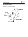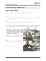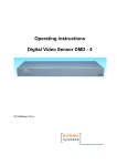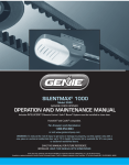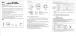
1
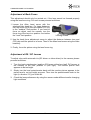
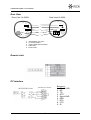
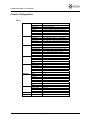
Vicon Industries Inc. Does not warrant that the functions contained in this equipment will meet your requirments or
that the operation will be entirely error free or perform precisely as discribed in the documentation. This system has
not been designed to be used in life critical situations and must not be used for this purpose.
Copyright © 2006 Vicon Industries Inc. All rights reserved.
Product specifications subject to change without notice.
Vicon and ist logo are registered trademarks of Vicon Industries Inc.
VICON INDUSTRIES INC., 89 ARKAY DRIVE, HAUPPAGE, NEW YORK 11788
TEL: 631-952-CCTV (2288) FAX: 631-951-CCTV (2288) TOLL FREE: 800-645-9116
24- Hour Technical Support: 800-34-VICON (800-348-4266)
UK: 44/(0) 1489-566300 WEB: vicon-cctv.com
Installation&
Operation Manual
IX 4000 L, IX 4000 H
Colour Camera
Dear Customer!
By selecting this VICON product you have chosen a professional device which
guarantees highest possible quality and reliability. We like to thank you very much for
your confidence in our products and kindly ask you to read the following instructions
carefully before commissioning the product in order to be able to take full advantage
of all quality features regarding this product line.
Contents
Page
General Information
¨ Safety Precautions
¨ Accessories and Additional Devices
3
3
Mounting the Camera
¨ Mounting the Camera to a Wall Mount
4
Commissioning the Camera
¨
¨
¨
¨
¨
¨
¨
Tips for Camera Location
Adjustment of Back Focus
Calibration of ES/DC- Lenses
Focusing the Camera Lens
Circuit points and operation
Remote Jack
Camera Configuration
5
6
6
7
8
9
10
Exhibit
¨
¨
¨
¨
¨
Troubleshooting
Technical Specifications
Cleaning and Care
Technical Support
Shipping Instructions
16
17
18
18
19
-2-
GENERAL INFORMATION
General Information
Safety Precautions
* Read these instructions carefully before commissioning the camera in order to
avoid damages caused by improper installation or use.
* Installation may only be carried out by authorised personnel according to the local
safety regulations.
* Operate the camera with the designated voltage only.
* Follow the safety instructions attached to the camera.
* Never use the camera for other purposes than designated.
* Repairs and adjustments at the camera may only be carried out by authorised
personnel.
* In case of ourdoor use you have to install the camera in a suitable weather
protection case incl. heating element.
* If any liquid or solid matter should get into the housing, disconnect the camera
from power supply and have it checked by your authorised dealer before re-using
(danger of electronic shock!).
* Do not disassemble the camera. To avoid electric shocks, never remove screws or
covers. There are no user-serviceable parts inside it. All maintenance may only be
carried out by authorised personnel according to the local safety regulations.
Install the camera by a least height of 2.30 m.
Composition
1.
Auto Iris Lens Plug
2.
Remote Plug
3.
L-Wrench
4.
C-Mount Adapter
5.
Instruction Manual
-3-
MOUNTING THE CAMERA
Mounting the Camera
Mounting the Camera to a Wall Mount
-4-
COMMISSIONING THE CAMERA
Commissioning the Camera
Tips for Camera Location
1.0 To avoid internal overheating:
- never expose the camera to direct sunlight without additional camera housing
- keep sufficient distance to direct heat sources.
2.0 Never install the camera at humid, oily or dusty locations without using an
additional housing. (without additional housing the camera is not suitable for
outdoor use!)
3.0 The camera should be installed out of reach (min. height: 2.30 m)
4.0 Do not aim the camera towards indoor lighting, the windows, the sunlight or the
sky (to get good pictures, camera and light should be aimed towards the object)
5.0 Reduce the picture detail to the
essential parts of the picture and place
the camera as close as possible to the
object (a smaller picture detail
guarantees sharper details).
6.0 Do not aim the camera towards a
window but instead towards the room.
7.0 Outdoors the camera should be
placed as high as possible so that the
horizon does not appear in the picture.
8.0 Avoid peak light as background (also
caused by reflections, e.g. window
panes).
-5-
wrong
right
COMMISSIONING THE CAMERA
Adjustment of Back Focus
This adjustment should only be carried out, if the lens cannot be focused properly
using the lens focus ring. For such a case proceed as follows:
1 Loosen the Allan head screw with the
attached Allan head key. For large distances,
turn the focus ring of the lens almost (0.5 cm)
to the "endless" limit position. If you need to
focus an object near the camera, turn the
focus ring of the lens to a position 1cm before
the "near" limit position.
Locking screws
2 Use the back focus adjustment screw to adjust the distance between lens and
CCD chip until the picture is in focus. Then fix the Allan head screw using the Allan
head key.
3 Finally, focus the picture using the lens focus ring.
Adjustment of ES / DC Lenses
To adjust a lens with automatic iris (DC driven or video driven) to the camera, please
proceed as follows:
1. Turn the level potentiometer (position: ES lenses at the lens itself, DC lenses: at
the camera) to the max. position H (turn right). The monitor picture then
appears to be too bright.
2. Slowly turn the level potentiometer back until the monitor picture appears to be
perfect and is not too bright anymore. Then turn the potentiometer back to the
right (in direction "H") just a little bit.
3. Check the lens performance by using the camera under different and/or changing
light conditions.
-6-
COMMISSIONING THE CAMERA
Focusing the Camera Lens
After you have selected the correct picture detail you have to adjust the lens focus.
The focus adjustment needs to be done with the iris fully open, since the camera has
the smallest depth of focus in this position. If the focus adjustment was not done with
the iris completely open, the picture would be sharp during the day but slowly getting
out of focus the more the light disappears. To fully open the lens, use a grey filter in
front of the lens, provided you are using a lens with automatic iris. Adjust the focus
while the iris is fully open using the lens focus ring. Make sure the most important
picture details are in optimum focus (use a service monitor). If it is not possible to
bring the picture into focus, please adjust the back focus of the camera as described
above.
If you intend to use I.R. illumination at a later stage, you must use an I.R. pass filter
together with the grey filter during focus adjustment to ensure that only I.R. light will
get through to the camera chip and the focus adjustment is done according to this
spectrum, only. Attention: I.R. light can only be used in combination with mono
cameras, not colour cameras!
-7-
COMMISSIONING THE CAMERA
Circuit points and operation
1
2
1. Lens connector
2. Menu buttons
DC - Lens
1. Controll 2. Controll +
3. Drive+
4. Masse
Attention:
This camera comes with a four times electronic zoom. With the buttons Ý(Tele) and
ß(Wide) you can operate the zoom function. With activated WDR function the
electronic zoom is not possible!
-8-
COMMISSIONING THE CAMERA
Rear View
Rear View IX 4000H
ELC
DC
V-Phase
Rear View IX 4000L
ELC
1
DC
V-Phase
2
Control
Control
3
4
AC 24V/ DC12V
5
1.
2.
3.
4.
5.
FG
Auto Shutter / DC Lens
LL Phasen adjust
Control (Remote) Connector
Video Out
Power input
Remote Jack
PC Interface
RS 232C PC Connector
RS 232/ RS 485 Converter
-9-
Belegung:
1. Frame GND
2. RD
3. TD
4. DTR
5. Signal GND
6. DSR
7. RTS
8. CTS
9. RI
COMMISSIONING THE CAMERA
Camera Configuration
Menu:
GENERAL
AWB
AE
D&N
WDR
PRIVACY
DISPLAY
INITIAL
EXIT
CAMERA ID
ZONE LABEL
NEGA/POSI
SHARPNESS
MIRROR
FREEZE
INITIAL
EXIT
WB MODE
RED CONT
BLUE CONT
PUSH AUTO
INITIAL
EXIT
BRIGHTNESS
FLICKERLESS
SHUTTER SPD
AGC MAX SET
MAX FLD SET
INITIAL
EXIT
D/N MODE
LEVEL
FILTER DLY
INITIAL
EXIT
WDR MODE
WDR LEVEL
BACK LIGHT
BLC LEVEL
INITIAL
EXIT
AREA
MASK
START X
END X
START Y
END Y
INITIAL
EXIT
CAMERA ID
ZONE LABEL
VERSION
INITIAL
OFF STATE
000 ~ 255
SET
POSITIV / NEGATIV
0 ~ 15
NORMAL, MIRROR, VERTIKAL, ROTATE
ON, OFF
ON, OFF
AUTO, HOLD, USER
NOT USE (AUTO, HOLD), 1 ~ 255 USER
NOT USE (AUTO, HOLD), 1 ~ 255 USER
NOT USE (AUTO, USER), OFF PUSH (HOLD)
ON, OFF
0 ~ 60
ON (PAL 1/100, NTSC 1/120)
1/250,1/500,1/1000,/1/2000,1/4000,1/10000
AGC OFF, LOW, MID, HIGH
OFF,2~20FLD,40FLD,80FLD,160FLD
ON, OFF
AUTO, DAY, NIGHT, EXT
0 ~ 200
0 ~ 15 SEC
ON, OFF
ON, OFF
0 ~ 15
ON, OFF
0 ~15
ON, OFF
1~4
ON, OFF
ON, OFF
ON, OFF
ON, OFF
ON, OFF
-10-
COMMISSIONING THE CAMERA
Setting Up The Menu
Press the MENU button to access the
GENERAL mode. Chage menu Point using the
UP and Down buttons. Change the status using the the LEFT / RIGHT buttons.
CAMERA ID
ZONE LABEL
NEGA/POSI
SHARPNESS
MIRROR
FREEZE
INITIAL
EXIT
General
000
SET
POSI
7
NORMAL
OFF
OFF
Camera ID:
In this Menu a number can be assigned to the camera (000 bis 255) wich will be
displayed on the monitor. Therefor the function CAMERA ID must be switched on in
the DISPLAY MENU.
Zone Label:
A title can be assigned to the picture. You can enter up to 10 characters. Move the
curser to character-enter location by using the LEFT / Right buttons. Select the
desired character by using the UP / DOWN buttons.
The factory default characters are:
A~Z, a~z, 0~9, ~, !, #, *, -, +, /, :, ;, ?, ., “, _, (, ),&, %, Ý, ß, Þ, Ü,
EXIT: Return to GENERAL MENU
If the DISPLAY MENU feature iss et to ZONE LABEL – ON, the name will be
displayed on the monitor.
NEGA/POSI:
Select Nega / Posi for a negativ or positiv screen display.
SHARPNESS:
Adjust the sharpness of the screen.
MIRROR:
Normal:
Mirror:
Vertikal:
Rotate:
Freeze:
Initial:
Exit:
Deactivation
Reverse turn Left or Right
Reverse turn Up or Down
Rotate the screen to 180°
Used when paused video is needed
INITIAL GENERAL MODE
RETURN to MAIN MENU
-11-
COMMISSIONING THE CAMERA
WB MODE
RED CONT
BLUE CONT
PUSH AUTO
INITIAL
EXIT
AWB
AUTO
NOT USE
NOT USE
NOT USE
OFF
WB MODE:
The following „White Balance“ functions can be selected:
AUTO:
White Balance is automatically set between 2500°K~9500°K
HOLD:
If PUSH AUTO is selected as ON, it fixes up the value setting the current WB
USER:
Manual WB. WB gains can set by using RED CONT, BLUE CONT
INITIAL:
INITIAL AWB MODE
EXIT:
RETURN to MAIN MENU
BRIGHTNESS
FLICKERLESS
SHUTTER SPD
AGC MAX SET
MAX FLD SET
INITIAL
EXIT
AE
25
OFF
NORMAL
MID
2 FLD
OFF
BRIGHTNESS:
Set up the desired brightness value. 0 ~ 60 BRIGHTNESS Level can be adjusted.
FLICKERLESS:
ON (PAL 1/100Sec., NTSC 1/120Sec.), OFF
SHUTTER SPD:
You can set a steady Shutter. NORMAL: 1/50 Sec. PAL / 1/60 Sec. NTSC.
Furthermore, the following values are possible: 1/250Sec., 1/500Sec., 1/1000Sec.,
1/2000Sec., 1/4000Sec., 1/10000Sec..
-12-
COMMISSIONING THE CAMERA
AGC MAX SET:
OFF: AGC deactivated
LOW: Gain is increased or decreased from 0 to 10dB automatically according to the
illumination.
MID: Gain is increased or decreased from 0 to 20dB automatically according to the
illumination.
High: Gain is increased or decreased from 0 to 30dB automatically according to the
illumination.
INITIAL:
INITIAL AE MODE
EXIT:
RETURN to MAIN MENU
D/N MODE
LEVEL
FILTER DLY
INITIAL
EXIT
D&N
AUTO
48
10
OFF
D/N MODE:
AUTO:
Depending on the illumination, the filter moves automatically in or out.
DAY:
The IR filter is always activated, colour image replication.
NIGHT:
The IR filter is always deactivated, b/w image replication
EXT:
The IR filter will be controlled by an external contact
LEVEL:
This level is setting up the turning point of the filter.
The following values are reference values:
15: ~40Lux, 28: ~30Lux, 48: ~20Lux, 88: ~10Lux, 128: ~5Lux, 200: ~1Lux
Please set up the value higher when you install this camera into the housing
(example: Level 128)
FILTER DLY:
According to user´s need, the turning delay time of 0 ~ 15 sec. can be given. This
value prevents the constant turning of the filter, eg. if cars with switched on lighting
are driving past.
INITIAL:
INITIAL D & N MODE
EXIT:
RETURN to MAIN MENU
-13-
COMMISSIONING THE CAMERA
WDR MODE
WDR LEVEL
BACK LIGHT
BLC LEVEL
INITIAL
EXIT
WDR
OFF
9
OFF
10
OFF
WDR MODE:
ON / OFF
WDR LEVEL:
This value sets the level of the WDR regulation. 0 ~ 15 Ranged and adjust the
brightness in WDR Mode.
BACK LIGHT:
ON / OFF
BLC LEVEL:
With this value the BLC Gain will be set. 0 ~ 15 Ranged and adjust the BLC Gain.
Attention:
A combination of both functions is not possible!
INITIAL:
INITIAL D & N MODE
EXIT:
RETURN to MAIN MENU
AREA
MASK
START X
END X
START Y
END Y
INITIAL
EXIT
PRIVACY
1
OFF
AREA:
Total 4 categories can be designated.
MASK:
Marks the area on the screen in state of ON.
START X:
Indicates the starting point on X axis.
-14-
COMMISSIONING THE CAMERA
END X:
Indicates the ending point on X axis.
START Y:
Indicates the starting point on Y axis.
END Y:
Indicates the ending point on Y axis.
INITIAL:
INITIAL PRIVACY MODE
EXIT:
RETURN to MAIN MENU
CAMERA ID
ZONE LABEL
VERSION
INITIAL
EXIT
Display
OFF
OFF
1.0
OFF
CAMERA ID:
To activate the CAMERA ID, so that this becomes visible on the screen.
ZONE LABEL:
To activate the 10-figure name of the camera, so that this becomes visible on the
screen.
VERSION:
Camera Version
INITIAL:
INITIAL DISPLAY MODE
EXIT:
RETURN to MAIN MENU
-15-
EXHIBIT
Exhibit
Troubleshooting
Error
Cause
No picture
-
No operating voltage (check red LED)
Coaxial connection interrupted (check video cable)
The picture is noisy
-
Insufficient light
The lens drive of the used lens (DC / AI) is not
properly adjusted to the camera (level too low)
The picture is too bright
-
The lens drive of the used lens (DC / AI) is not
properly adjusted to the camera (level too high)
Too much peak light; change camera location or
activate backlight function of the camera
-
The picture is not sharp
-
Focus not adjusted properly
Back focus not adjusted properly
When used outdoors: heater defective; front pane of
camera housing gets steamy
The picture is distorted
-
Different GND potentials between camera and
monitor; use opto coupler (e.g. VPT from videotronic)
Bad connections
-
Wrong 75 W termination
Shield of video cable interrupted
Ghost image
Synchronisation of cameras does not work properly
-
No or bad linelock connection between camera (12
V/DC version) and power adapter
Mains plug twisted; turn the mains plug by 180° to
change the linelock phase
Please contact your authorised dealer with an exact failure description if none of the
above remedy measures fixes your problem.
-16-
TECHNICAL SPECIFICATIONS
Technical Specifications
Model
IXION 4000L / H (PAL)
CCD SENSOR
2:1 Interlace transfer 1/3“ Double Scan CCD
Effective Pixels
752 (H) x 582 (V)
Reolution
Onscreen Display
480 TV-Lines
0,1Lux (Normal Mode)
0.001Lux (2x DSS, b/w Mode)
yes
Signal to Noise Ratio (SNR)
> 50dB (AGC Off/ B/W Mode)
AGC
adjustable, off 10 dB, 20 dB, 30 dB
Synchronisation
Linelock at 24 VAC/ Intern at 12VDC and 230VAC
Backlight / WDR
WDR and BLC adjustable
Day Night
Colour/ B/W / Auto (Filter Auto Change) / Ext via contact
Flickerless
yes 1/ 100 Sek.
Auto Shutter
1/50 Sec. ~ 1/10000Sec.
White Balance
AWB 2500°K~9500°K / MWB / Push Auto
Sens up / DSS
2~20FLD,40FLD,80FLD,160FLD
RS 485
yes
Video output signal
Composite 1VSS,, 75 Ohm
Private zones
yes 4 independently adjustable
Picture Flip
up / down, left / right, 180°
Elektr. Zoom
yes
Lens Mount
Operating Temperature
DC CS Mount, C Mount (incl. adaptor ring)
IXION 4000L: 12V DC / 24VAC, max 0,5A (6W)
IXION 4000H: 100 VAC ~ 240 VAC, 6W
-10°C ~ +50°C (recommended -5°C ~ +40°C)
Dimensions
65 x 65 x 125 mm
Weight
~ 430g
Sensitivity
Power
-17-
CLEANING AND CARE & TECHNICAL SUPPORT
Cleaning and Care
Before you start to clean the camera body, disconnect the unit from power supply.
For reasons of electrical safety never clean the camera with water or other liquid
matters and never put the camera under water. To clean use a soft dry cloth.
Cleaning the camera inside is strictly forbidden and may only be done by your
authorised dealer.
Since all camera functions are self adjusting and the camera does not contain any
parts or components that are subject to wear we advise you not to open the camera
(except for the flap for settings), unless the camera appears to be defective.
Make sure to include these instructions when handing the camera over to third
parties.
Technical Support
Should you have any problems during installation you can reach our Technical
Hotline under the following telephone number: +44 (0) 1489 - 566 300.
-18-
SHIPPING INSTRUCTIONS
Shipping Instructions:
Use the following procedure when returning a unit to the factory:
1. Call or write Vicon for a Return Authorization (R.A.) at one of the locations listed
below. Record the name of the Vicon employee who issued the R.A.
Vicon Industries Inc.
89 Arkay Drive
Hauppage, NY 11788
Phone: 631-952-CCTV (2288); Toll Free: 1-800-645-9116
Fax:
631-951-CCTV (2288)
For service or returns from countries in Europe, contact:
Vicon Europe Ltd:
Brunel Way
Fareham, PO 15 5TX
United Kingdom
Phone: +44 (0) 1489 566 300
Fax:
+44 (0) 1489 566 322
2. Attach a sheet of paper to the unit with the following information:
a. Name and address of th ecompany returning the unit
b. Name of the Vicon employee who issued the R.A.
c. R.A. number
d. Brief description of the installation
e. Complete description of the problem and circumstances under which it
occurs
f. Unit’s original date of purchase, if still under warranty
3. Pack the unit carefully. Use the original shipping carton or ist equivalent for
maximum protection.
4. Mark the R.A. number on the outside of the carton on the shipping label.
-19-
Vicon Industries Inc.
Corporate Headquarters
89 Arkay Drive
Hauppage, New York 11788
631-952-CCTV (2288) 800-645-9116
Fax: 631-951-CCTV (2288)
Vicon Europe
Headquarters
Brunel Way
Fareham, PO 15 5TX
United Kingdom
+44 (0) 1489 566300
Fax: +44 (0) 1489 566322
Brussels Office
Planet II - Unit E
Leuvensesteenweg 542
B - 1930 Zaventem
Belgium
+32 (2) 7128780
Fax: +32 (2) 7128781
Far East Office
Unit 5, 17/F, Metropole Square
2 On Yiu Street, Shatin
New Territories,
Hong Kong
(852) 2145-7118
Fax: (852) 2145-7117
Internet Address: www.vicon-cctv.com