1
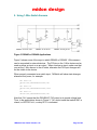
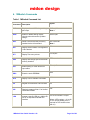
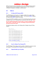
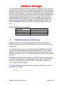
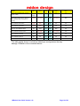
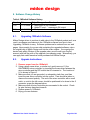
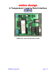
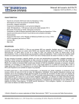
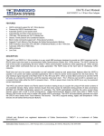
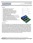
midon design A 1-Wire Serial Interface 1WSwitch Figure 1 1WSwitch 1WSwitch User Guide Version 1.02 November 18, 2008 1WSwitch User Guide Version 1.02 Page 1 of 28 midon design 1. Table of Contents 1. Table of Contents ..........................................................................................2 1.1. List of Tables ..........................................................................................3 1.2. List of Figures .........................................................................................3 2. Introduction ....................................................................................................4 3. Installation......................................................................................................6 4. Using 1WSwitch.............................................................................................7 5. Using 1-Wire Switch Sensors ........................................................................9 6. 1WSwitch Commands .................................................................................10 6.1. Using the SET Command .....................................................................12 6.2. The DIS Display Output ........................................................................13 6.2.1. DIS output explanations ................................................................13 6.3. Using the EEP and MEM Commands...................................................14 6.4. TMP Output Display .............................................................................14 6.5. Missing Sensor Display ........................................................................15 6.6. Options .................................................................................................16 6.6.1. On Board ADC Display (DAD) .......................................................16 6.6.2. Once Per Minute Time Display (DTI).............................................16 6.6.3. Enable DS2408 Input Poll (EIN) ....................................................16 6.7. DS2408 Based Relay and LED Usage .................................................17 7. J5 Usage .....................................................................................................18 8. Software Change History .............................................................................20 8.1. Upgrading 1WSwitch Software .............................................................20 8.2. Upgrade Instructions ............................................................................20 9. Trouble-Shooting Problems with 1WSwitch .................................................22 10. Error Messages........................................................................................23 11. 1WSwitch Schematic ...............................................................................24 12. 1-Wire Sensors ........................................................................................25 13. Legal Disclaimer.......................................................................................28 1WSwitch User Guide Version 1.02 Page 2 of 28 midon design 1.1. List of Tables Table 1 1WSwitch Command List .......................................................................10 Table 2 EIN Settings Recommended..................................................................17 Table 3 RJ-12 Pin-outs in use.............................................................................18 Table 4 1WSwitch Software History....................................................................20 Table 5 Common 1WSwitch Problems and Resolutions.....................................22 Table 6 1WSwitch Error Messages.....................................................................23 Table 7 Reset Type Messages ...........................................................................23 Table 8 Midon Design – Available/Compatible Sensors .....................................26 1.2. List of Figures Figure 1 1WSwitch................................................................................................1 Figure 2 Location of Connectors ...........................................................................6 Figure 3 DS2405 or DS2406 Applications ............................................................9 Figure 4 Connector J5 RJ-12 Pin-out..................................................................18 Figure 5 1WSwitch Top View ..............................................................................21 Figure 6 1WSwitch Schematic ............................................................................24 Figure 7 DS2405 Pinout......................................................................................25 Figure 8 DS2406 & DS2407 Pinout ....................................................................25 Figure 9 DS2408 Pinout......................................................................................26 Figure 10 DS2438 Pinout....................................................................................26 1WSwitch User Guide Version 1.02 Page 3 of 28 midon design 2. Introduction Thank you for your purchase of the 1WSwitch 1-Wire Serial Interface. The following instructions will assist you in configuring and operating the product. 1WSwitch is a stand-alone 1-Wire interface providing standard serial commands to control the Dallas/Maxim 1-Wire bus and some specific devices used on it. Sensors can be polled on a regular basis (from 1 to 99 minutes), or manually interrogated. In a typical application, 1WSwitch is connected to a serial port on a PC. Serial interface software is then used to gather the data received from 1WSwitch and process it. Users have interfaced 1WSwitch into the HomeSeer product, which can be used to automate lights, HVAC, sprinklers, and other devices, based on the sensor readings from 1WSwitch. The 1WSwitch provides a serial interface for the following 1-Wire devices: • Multiple DS2438-based Voltage Sensors • Multiple DS2405 input/output sensors • Multiple DS2406 (or DS2407) input/output sensors • Up to 20 1WIO relay interface modules (or equivalent DS2408 based relay module) available from Midon Design • Up to 10 1WIO LED modules (available from Midon Design) • One 1WIO Input module (available from Midon Design) 1WSwitch has the following features: • Real-time display of state changes for DS2405, DS2406 or DS2407 sensors • On-board voltage sensor. • Jumper-less provisioning - all configuration settings are stored in non-volatile memory • Up to 60 1-Wire are sensors supported • Simple instruction set with a Help prompt for recalling command names • Easy to delete sensors, if they are no longer required, using the DEL command • 1-Wire bus errors are flagged when they occur • Continuous poll for ALL sensors - 1WSwitch will notify you when any switch sensor has changed state or is connected or disconnected, providing that they have been previously registered by 1WSwitch via the INI command. Very useful for locating intermittent 1-Wire bus problems or for real-time polling of contact sensors. 1WSwitch User Guide Version 1.02 Page 4 of 28 • midon design Manual Poll of sensor readings. While 1WSwitch is normally used for continuous (from 1 to 99 minute intervals) polling of sensor readings, it can also be used manually to take sensor readings on command from the serial interface. 1WSwitch User Guide Version 1.02 Page 5 of 28 midon design 3. Installation To complete this project, you will need to connect a 12 to 16 Volt (AC or DC) transformer to the terminal J1 (see Figure 2 for the location of J1). If you intend to power 1WIO relay units from the 12V output of 1WSwitch, the transformer needs to supply at least 350mA (250mA for 1WIO and 100mA for 1WSwitch) per 1WIO relay unit, up to a maximum of 800mA, or 2 1WIO relay units. Beyond that, supplemental powering will need to be provided for the off-board units. Otherwise, any 12 to 16 Volt adapter capable of at least 100mA will do. If you are using a sensor network of 1-Wire devices, connect them now to either connector J3 or J5. Figure 2 Location of Connectors 1WSwitch User Guide Version 1.02 Page 6 of 28 midon design 4. Using 1WSwitch Connect up a straight-through serial cable between 1WSwitch's J4 connector and your PC. Open up HyperTerminal (or equivalent terminal emulator program) on your PC. Configure it to 9600 BPS, No parity, 8 bits, 1 start bit and NO hardware handshaking (very important!). Power up the 1WSwitch and configure the unit for the devices that you have connected. The start-up sequence will look like this: 1WSwitch v1.01 2008-10-12 MidonDesign.com 2245 Reset type: C2 Poll interval = 255 minutes Serial # Display = On Time Display = On OnBoard ADC Display = On Enable INP = On Debug = On SUN 00:00:00 > We recommend that you next use the ERA command for first time use, to erase the EEPROM. This will remove any previous information that may have been stored in the EEPROM. Next use the INI command to register any 1-Wire devices connected to the 1-Wire bus. If you get any error messages, it is most likely a result of a bad connection to the devices. Verify them. Typically, a "OW bus error" message indicates that a sensor has been installed in reverse, or that there is a short on the bus. Note: an ERA command is not required every time that an INI command is issued. It should only be required for first time use. If you believe that 1WSwitch has not found all 1-Wire devices, re-issue the INI command. Now program the configuration by using the SET command. Just type SET and the program will prompt you for the required settings; polling interval, display settings, and finally the real time clock setting. >set Poll interval = 01 Serial # Display = on Time Display = off OnBoard ADC Display = on 1WSwitch User Guide Version 1.02 Page 7 of 28 midon design Enable INP = off Debug = off Set Clock (d,h,m,s): 01,14,30,00 The options are further defined later in this manual. All are independently adjustable without using the SET command. To verify that your setup is working properly, you could next use the TMP command to perform an immediate sensor reading. The output of the TMP command should look like the sample below (the exact output will depend on what type of sensors and how many you have installed). SUN 14:30:44 Reading Sensors... Switch #01[C90000005F31C412]=On Switch #02[4A0000005F3A1512]=On Switch #05[170000002A345005]=On Switch #06[4F0000002A15C405]=On Switch #07[A60000002A30A405]=On Switch #08[620000002A1B9C05]=Off Switch #09[410000002A1A3A05]=On Switch #10[CC0000001FBD2605]=Off Switch #11[8F0000001FB60105]=Off Switch #12[E60000001FB82D05]=Off Switch #13[A20000001FB6C705]=Off Switch #14[290000005F365412]=Off J2 Pin 3 Voltage = 00.40V > It is highly recommended that you next turn off (or on) all the connected switches. This will reset the saved state in the EEPROM, which may not match the physical configuration – the state of all switch sensors is normally preserved through a power cycle. Use the ONA or OFA command for all DS2406’s (or DS2407) and the TOG command for DS2405’s. If there are no apparent errors, you are ready to use 1WSwitch. Enjoy! 1WSwitch User Guide Version 1.02 Page 8 of 28 midon design 5. Using 1-Wire Switch Sensors Figure 3 DS2405 or DS2406 Applications Figure 3 shows some of the ways in which DS2405 or DS2406 1-Wire sensors can be connected to external devices. The PIO pin on the 1-Wire device can be used as either an input or as an output. When used as an input, make sure that you set the 1-Wire sensor to the off state, otherwise the PIO input changes will not be visible to the device. When properly connected as a switch input, 1WSwitch will show state changes whenever they occur, for example: FRI 08:11:10 Switch #01[C90000005F31C412]=On > FRI 08:11:12 Switch #01[C90000005F31C412]=Off > FRI 08:11:17 Switch #01[C90000005F31C412]=On Note that “On” means that the DS2405/6/7 PIO output is at ground voltage level. Thus, in the applications shown in Figure 3, “On” would mean that switch SW1 is closed, or LED DS1 is lit, or relay RLY1 is activated. 1WSwitch User Guide Version 1.02 Page 9 of 28 midon design 6. 1WSwitch Commands Table 1 1WSwitch Command List Syntax Command Description DAD Display on-board ADC voltage during poll output DAD<on|off> Note 3 DEB Enable or disable debug outputs Use only when directed to by Midon Design DEB<on|off> DEL Delete a sensor that was previously installed via the INI command DEL<sensorid> Note 1 DIS Display serial numbers of all registered 1-Wire devices DIS DTI Display Time every minute EEP Display and change specific EEPROM memory locations EEP <start location><cr> EIN Enable polling of 1WIO sensors for input status EIN<on|off> ERA Erase the entire EEPROM HLP Display a list of available commands INI Register all connected 1-Wire sensors INP Display the status of bits 4-7 of the first connected DS2408 INP LED Actuate a specific LED on a 1WIO LED unit or an equivalent DS2408 LED interface LED <LED number> <on|off> 1WSwitch User Guide Version 1.02 DTI<on|off> ERA HLP INI Where <LED number> = 01 to 80 or A for All (the leading zero is required for LED numbers less than 10) Page 10 of 28 midon design Syntax Command Description MEM Display and change specific memory locations MEM <start location><cr> ONA Turn ON a DS2406 or DS2407 (channel A only) ONA <sensorid> Where xx is a decimal number corresponding to the DS2406/7 sensor number as shown in the DIS display OFA Turn OFF a DS2406 or DS2407 (channel A only) OFA <sensorid> Where <sensorid> is a decimal number corresponding to the DS2406/7 sensor number as shown in the DIS display RLY Actuate a specific 1WIO relay RLY <relay number> <on|off> Where <relay number> = 01 to 80 or A for All (the leading zero is required for relay numbers less than 10) SCK Set Clock SET Configure all system parameters SID Show the Serial Number ID for the 1Wire Devices SID <on|off> SPT Set the polling interval in minutes SPT <xx> Where <xx> is a decimal number from 00 to 99. 00 will disable polling. TIM Display Time from the Real Time Clock TIM TMP Display sensor readings of all connected 1-Wire Devices in either verbose (includes serial numbers) or non-verbose mode TMP TOG TOGgle a DS2405 sensor output from TOG <sensorid> Where <sensorid> is a decimal 1WSwitch User Guide Version 1.02 SCK dd, hh, mm, ss<cr> dd = 01 to 07 (Sunday = 01) hh = 00 to 23 mm = 00 to 59 ss = 00 to 59 Note 2 SET Page 11 of 28 midon design Command Description Syntax on to off or from off to on number corresponding to the DS2405 sensor number as shown in the DIS display VER Displays the current version of the software loaded VER ZZZ Performs a soft reset of 1WSwitch ZZZ Notes 1. The <sensorid> parameter in the commands above refers to the sensor number as shown via the DIS command. Leading zeros are required. See the DIS command explanation below. 2. Most commands do not require a Carriage Return (enter) following the parameter or command input. One exception is the SCK command. Commands requiring a sensor number input will require a CR if the sensor number is only a single digit. 3. Command parameters are shown in angled brackets “< >”. Where only certain options are permitted, they are indicated with a vertical pipe character “|”. 6.1. Using the SET Command The SET command has multiple parameters. All option parameters are also adjustable via discrete commands. >set Poll interval = 01 Serial # Display = on Time Display = off OnBoard ADC Display = on Enable INP = off Debug = off Set Clock (d,h,m,s): 01,14,30,00 Poll Interval This parameter determines the time between sensor readings. Set to 00 to stop polling. Enter the time in decimal minutes. Use the SPT command to adjust only this parameter. Serial # Display Set this to On if you want 1WSwitch to display the 1-wire ID of all sensors. Use the SID command to adjust only this parameter. Time Display Set this to On if you want 1WSwitch to display the voltage as measured at connector J2 pin 3. Use the DAD command to adjust only this parameter. 1WSwitch User Guide Version 1.02 Page 12 of 28 midon design OnBoard ADC Display Set this to On if you want 1WSwitch to display the output from the onboard Analog to Digital Converter connected to pin 3 of J2 and referenced to ground on pin 4 of J2. Use the DAD command to adjust only this parameter. Debug Set this to On only if requested to by Midon Design in case troubleshooting details are required. Otherwise, your display will be corrupted with outputs that are meaningless. Use the DEB command to adjust only this parameter. Set Clock Enter the current time here as Day of week (01 = Sunday) followed by Hour, Minutes, and lastly, Seconds. Use the SCK command to adjust the clock at any time. Time is entered and displayed in 24 hour (military) format. 6.2. The DIS Display Output Sample DIS Output >dis 01 C90000005F31C412 02 4A0000005F3A1512 03 A400000001042829 04 7400000001044629 05 170000002A345005 06 4F0000002A15C405 07 A60000002A30A405 08 620000002A1B9C05 09 410000002A1A3A05 10 CC0000001FBD2605 11 8F0000001FB60105 12 E60000001FB82D05 13 A20000001FB6C705 14 290000005F365412 15 A0000800E93A8F10 16 3D0000004CC69826 DS2406 DS2406 DS2408 DS2408 DS2405 DS2405 DS2405 DS2405 DS2405 DS2405 DS2405 DS2405 DS2405 DS2406 DS1820 DS2438 OK OK OK OK OK OK OK OK OK OK OK OK OK OK OK OK P P P P P P P P P P P P P P P P Poll interval = 01 minutes Serial # Display = On Time Display = Off OnBoard ADC Display = On Enable INP = Off Debug = Off FRI 20:11:12 6.2.1. DIS output explanations The DIS commands shows all sensors registered by 1WSwitch. The output shows the memory locator for the sensor, known as the sensor ID, the sensor 1WSwitch User Guide Version 1.02 Page 13 of 28 midon design serial number, which is programmed into the sensor at the factory, followed by the CRC check status and presence status. An OK will be displayed following the Sensor ID to indicate that the Cyclic Redundancy Counter (CRC) checksum of the sensor's serial number is good. If the serial number has a bad CRC, an NG will be displayed. The checksum is validated during the output of the sensor display. Following the CRC status, a P or M will be displayed to show the connectivity of the sensor. A P is displayed is the sensor is present, and an M when it is missing from the 1-Wire bus. Following a display of the sensors installed, the output of the DIS display then shows the 1WSwitch settings that you entered via the SET command. 6.3. Using the EEP and MEM Commands These two commands provide direct access to the memory of 1WSwitch and, as such, should be used with extreme caution. After entering the command, 1WSwitch will display the contents of memory. Use the “;” key to advance to the next memory location, and use the “/” key to go to the previous memory location. Both commands will wrap around at the appropriate memory boundaries. To change a memory location using the MEM command, enter a hexadecimal value after the memory contents are displayed. Valid inputs are from “00” to “FF”. If the memory location is read-only, an “? Entry Error” error message will be displayed. To change a memory location using the EEP command, enter a double hexadecimal value after the memory contents are displayed. Valid inputs are from “0000” to “FFFF”. In both commands, a carriage return (enter) following display of the memory contents will terminate the command. Obviously, these commands can be potentially harmful to the operation of 1Wswitch if not used properly. Midon Design recommends that the EEP and MEM commands only be used under guidance from our support staff. 6.4. TMP Output Display The TMP output and polled output displays are identical. An example is shown below. 1WSwitch User Guide Version 1.02 Page 14 of 28 midon design FRI 08:10:41 Reading Sensors... Switch #01[C90000005F31C412]=Off Switch #02[4A0000005F3A1512]=On Switch #05[170000002A345005]=Off Switch #06[4F0000002A15C405]=On Switch #07[A60000002A30A405]=Off Switch #08[620000002A1B9C05]=Off Switch #09[410000002A1A3A05]=On Switch #10[CC0000001FBD2605]=Off Switch #11[8F0000001FB60105]=Off Switch #12[E60000001FB82D05]=Off Switch #13[A20000001FB6C705]=On Switch #14[290000005F365412]=On J2 Pin 3 Voltage = 00.42V Voltage #16[3D0000004CC69826]=01.89V 05.22V 01mV > The output starts with a time reading, followed by switch status, 1WIO input status (if enabled by the EIN command), DS2438 voltage sensor status and onboard ADC voltage (if enabled by the DAD command). The first voltage reading displayed for a DS2438 voltage sensor is always the external voltage from the DS2438 input. This is followed by the VDD voltage and lastly by the DS2438 “current” sensor voltage, which corresponds to current depending on what value of resistor is connected across the current terminals of a DS2438. Note: the time is always displayed once per minute, on the minute, except during a polling interval or TMP display, or if disabled by the DTI Off command. See the explanation of the DTI command. 6.5. Missing Sensor Display 1WSwitch continuously polls for the presence of all sensors that have been registered via the INI command, in other words, for sensors that are known to 1WSwitch. If any of the sensors are detected as missing, the following display will result: >MON 09:52:34 Missing Sensor #06 [4F0000002A15C405] When the sensor is re-connected, the display will look like this: >MON 09:57:01 Restored Sensor #06 [4F0000002A15C405] 1WSwitch User Guide Version 1.02 Page 15 of 28 midon design Polling of sensors is done sequentially and very fast (milliseconds per sensor). The more sensors that are equipped, however, the more time it will take for 1WSwitch to recognize a missing or re-added sensor. 6.6. 6.6.1. Options On Board ADC Display (DAD) The DAD (Display A to D) option is to enable or disable the on-chip voltage sensor (Analog to Digital Converter, or ADC). The command DAD on enables the display and DAD off disables the display. The on-board ADC is available on pin 3 of J2 and referenced to the ground pin available as pin 4 of J2. Be careful with connections to this ADC input. Note: you are connecting directly to the processor, and input voltages greater than 5 volts, or less than –0.6 volts, will damage the processor pin and possibly the processor itself. Activating the display results in the following kind of display during a Polling interval: > FRI 08:10:41 Reading Sensors... Switch #01[C90000005F31C412]=Off Switch #02[4A0000005F3A1512]=On Switch #05[170000002A345005]=Off Switch #06[4F0000002A15C405]=On Switch #07[A60000002A30A405]=Off Switch #08[620000002A1B9C05]=Off Switch #09[410000002A1A3A05]=On Switch #10[CC0000001FBD2605]=Off Switch #11[8F0000001FB60105]=Off Switch #12[E60000001FB82D05]=Off Switch #13[A20000001FB6C705]=On Switch #14[290000005F365412]=On J2 Pin 3 Voltage = 00.42V Voltage #16[3D0000004CC69826]=01.89V 05.22V 01mV > 6.6.2. Once Per Minute Time Display (DTI) The DTI (Display TIme) option is used to enable or disable the once-per-minute time display. The command DTI on enables the regular time display. 6.6.3. Enable DS2408 Input Poll (EIN) 1WSwitch User Guide Version 1.02 Page 16 of 28 midon design The EIN (Enable INput) option enables or disables a regular poll of one DS2408 connected on the 1-Wire bus, the one with the lowest sensorid. Setting EIN off is generally only required for users of MD2088 LED displays, which uses a DS2408 to drive the LED’s, since the normal poll of a DS2408 will set the high order bits (4 to 7) of the DS2408 and corrupt the LED display for those bits. Setting EIN Off is done to permit reading of the input ports (4 to 7) of the 1WIO sensor since clearing those bits would normally result in false readings. This option has no affect on the INP command and as a result, user’s with MD2088 displays will experience corruption of their LED displays if the INP command is used. The command EIN on will enable regular polling of the 1WIO inputs during a poll cycle. Table 2 EIN Settings Recommended 1WIO Used MD2083 4 Relay Output MD2084 4 Input MD2088 8 LED Ouput 6.7. Recommended EIN Setting Not important On Off DS2408 Based Relay and LED Usage 1WSwitch software has the ability to actuate relay modules based on the DS2408 port expander chip from Dallas/Maxim. One such module is the Midon Design 1WIO. The 1WSwitch supports up to 40 1WIO relay modules (MD2083) and the RLY command input then actuates those relays (numbered from 01 to 80). Relay numbers 01 to 04 are for the first connected 1WIO module, relay numbers 05 to 08 are for the second, and so on. Note that the leading zero for the relay number is required. The LED command works the same way as the RLY command except that there are 8 LED’s per 1WIO acted on instead of 4 relays per 1WIO. Up to 10 1WIO LED units are supported for a total of 80 LED’s. Remember to set EIN OFF when using a 1WIO LED Module. The RLYA<on|off> command will affect all connected 1WIO relays, and/or all connected LED modules. >rly01on Relay Group #01=On,Off,Off,Off 1WSwitch User Guide Version 1.02 Page 17 of 28 midon design 7. J5 Usage J5 is an RJ-12 connector, which is equivalent to a phone connector, except that it has 6 pins instead of just 4 (or 2). J5 is connected to the One Wire bus and can be used for adding connectivity to One Wire busses configured for RJ-11/12 connection. The pin-out of the J5 connector is shown in Figure 4. Figure 4 Connector J5 RJ-12 Pin-out Pin 1 is derived from the power supply feeding 1WSwitch. It is DC rectified, so it will not matter if your power supply is AC only. Please note that this pin-out may be different than that of your 1-Wire sensors. At one time, there was no established standard pin-out for the RJ-12 wiring and, as a result, different manufacturers have chosen to use the pins in various ways. The common pins (DQ and Ground) have remained the same for all manufacturers, however, as of the time of writing this manual. These pins are shown in color in the table below. Some of the published pin-outs available today are shown in the table below. Please take caution in connecting up your 1Wire sensor to 1WSwitch to avoid damaging the sensor. Table 3 RJ-12 Pin-outs in use Device Pin 1 Pin 2 Pin 3 Pin 4 Pin 5 Pin 6 +5VDC GND DQ GND N/C DC Supply Midon Design MD2004 TEMP05 N/C +5VDC DQ GND N/C N/C Midon Design MD2104 1WSwitch DC Supply +5VDC DQ GND N/C N/C Midon Design MD2204 LOG08 DC Supply +5VDC DQ GND N/C N/C N/C +5VDC DQ GND N/C N/C DC Supply +5VDC DQ GND N/C N/C Dallas/Maxim wiring standard (published Oct 2001) Midon Design MD3009 Temp Sensor Midon Design MD3020x Temp and Humidity Sensor 1WSwitch User Guide Version 1.02 Page 18 of 28 midon design Device Pin 1 Pin 2 Pin 3 Pin 4 Pin 5 Pin 6 DC Supply +5VDC DQ GND N/C N/C Simon Atkins’ Hub (shown for reference only. 1WSwitch does not support this device) +5VDC DC Supply DQ GND DC Supply GND AAG TAI8550 Combo Switch +5VDC GND DQ GND N/C N/C AAG TAI8520 Temp Sensor +5VDC GND DQ GND N/C N/C AAG V3 1-Wire Weather Station N/C +5VDC DQ GND GND N/C AAG TAI8540A Humidity Sensor N/C N/C (GND?) DQ GND N/C (+5VDC?) N/C AAG TAI8555 Latch Relay N/C GND DQ GND N/C N/C AAG TAI8585 Counter Kit N/C N/C DQ GND N/C N/C AAG DS9097U-S09-X N/C GND DQ GND +5V N/C Midon Design MD208x Relay and LED Sensor (1WIO) The table entries shown in red above indicate pin configurations that may damage 1WSwitch or the connected sensor. 1WSwitch User Guide Version 1.02 Page 19 of 28 midon design 8. Software Change History Table 4 1WSwitch Software History Version Date Major Changes from Previous Loads 1.02 11/17/2008 • Minor glitch in INI command • Added “Found…” message to INI output 1.01 10/12/2008 • Final production version of software 8.1. Upgrading 1WSwitch Software Midon Design strives to continue to add value to the 1WSwitch product and, as a result, we release new features to the 1WSwitch software from time to time. Upgrading 1WSwitch is easy. Software updates can be ordered from our web pages. Upon receipt of your new chip containing the upgraded software, return the original chip to Midon Design and cite the order number. If we receive the device back within 30 days of the upgrade order, we will credit your PayPal account with half the price of the upgrade, less shipping costs. Alternatively, you can apply that credit towards a future purchase from Midon Design. 8.2. Upgrade Instructions 1. Remove power from the 1WSwitch! 2. Using a small screw-driver, or similar tool, gently remove U1, the 68HC908KX8 micro-controller, by inserting the screw-driver between the micro-controller and the DIP socket that it is inserted to. The location of U1 is shown in Figure 5. 3. Make sure that you are grounded, or adequately static free, and then insert the new micro-controller into the socket. Care should be taken to observe the correct polarity. The end of the micro-controller with a small notch, or a dot in the left corner, should be positioned to be close to the J1 connector as per the diagram below. 4. Make sure that all micro-controller pins are seated in the socket. Check for pins that may have bent inwards. 5. Restore power to 1WSwitch. 6. Enjoy your new features. 1WSwitch User Guide Version 1.02 Page 20 of 28 midon design The following figure shows the location for installing the new processor, U1. Figure 5 1WSwitch Top View 1WSwitch User Guide Version 1.02 Page 21 of 28 midon design 9. Trouble-Shooting Problems with 1WSwitch The most common problems associated with using 1WSwitch are listed in the following table. If these instructions do not result in better results with your 1WSwitch, please feel free to contact Midon Design at [email protected]. We would be more than happy to assist you. Table 5 Common 1WSwitch Problems and Resolutions Problem I cannot display 1WSwitch output on my PC I cannot see what I type on Hyperterm I added a new sensor and now all I get is “OW Bus Error” messages I was able to add a new sensor but all I get is “???” readings from it. I removed a sensor from my wiring and now all I get is “???” readings from it. I have a MD2088 LED display and LED’s 5 to 8 turn on by themselves and will not turn off 1WSwitch User Guide Version 1.02 Possible Causes Ensure that you are connected with the proper settings (9600 bps, no parity) and that you are using a straightthrough, not a null-modem, serial cable This is normal for Hyperterm versions that come pre-packaged with some versions of Windows. Upgrade to a commercial version of Hyperterm or use different terminal emulator software. Your sensor is probable reversed on the 1-Wire bus, OR, there is a short on the bus. Check your wiring. Check your 1-Wire bus wiring. You may need to add a 100 ohm resistor in series with a new leg of bus that you added. Delete the sensor (use the DEL command) to eliminate the ??? readings. Disable DS2408 input polling via the EIN OFF command Page 22 of 28 midon design 10. Error Messages Table 6 1WSwitch Error Messages Message Description ? Entry error You have made a syntax error in entering a command or a parameter You tried to add more than 60 1-wire devices via the INI command. 1WSwitch has sufficient memory for only 60 unique 1-Wire device ID’s. 1WSwitch could not communicate to the device that you were trying to access. Check your 1-Wire bus wiring, or make sure that you are specifying the correct sensor number. Common to any 1-wire bus read operation. This error indicates that something is preventing the bus from changing state. Typical causes include shorts on the bus, or a reversed sensor. A parameter was not received in response to a command within 1 minute. Only issued when communication with a DS2408 fails. Try the command again. If it persists, you may have a 1-Wire bus wiring problem. ! Memory is full Not installed OW bus error ? Input Timeout ? Device Write Error Table 7 Reset Type Messages Reset Type (hex) 02 04 08 10 20 40 80 Cause of Reset Low voltage – the power supply fell below spec Monitor Mode reset entry – should never be seen Illegal Address – something in the software caused access to an illegal address. Contact Midon Design Illegal Op Code reset – something in the code happened. If this was not the result of a ZZZ command, contact Midon Design Watchdog timeout. The software was busied out with something. If this occurs too frequently, contact Midon Design User reset – you issued a ZZZ command Power on reset – a normal entry Binary combinations of the types above are possible and normal. For example, a power up reset will usually result in a type 82 message (Power on reset plus low voltage reset) and a ZZZ reset will result in a type 50 message. 1WSwitch User Guide Version 1.02 Page 23 of 28 midon design 11. 1WSwitch Schematic Figure 6 1WSwitch Schematic Figure 6 shows all components as equipped on a 1WSwitch. The PCB also has mounting connections for an optional DS2438 that can be used as a voltage sensor for external voltages (from zero to 5Volts) through the AIN connection on J3. 1WSwitch User Guide Version 1.02 Page 24 of 28 midon design 12. 1-Wire Sensors Figure 7 DS2405 Pinout Figure 8 DS2406 & DS2407 Pinout 1WSwitch User Guide Version 1.02 Page 25 of 28 midon design Figure 9 DS2408 Pinout Figure 10 DS2438 Pinout Table 8 Midon Design – Available/Compatible Sensors Midon Part Number MD3014 MD3023 MD2083 MD2084 MD2088 MD3020E Description DS2405 Switch Sensor DS2406 Switch Sensor 1WIO 4 Relay Output 1WIO 4 Input 1WIO 8 LED Output Humidity Sensor (humidity will display as voltages only) 1WSwitch User Guide Version 1.02 Page 26 of 28 midon design MD3020G MD3020H 1 Relay Output 1 LED output 1WSwitch User Guide Version 1.02 Page 27 of 28 midon design 13. Legal Disclaimer YOUR USE OF THIS PRODUCT IS AT YOUR OWN RISK. YOU ASSUME FULL RESPONSIBILITY AND RISK OF LOSS RESULTING FROM THE USE OF THIS PRODUCT. MIDON DESIGN WILL NOT BE LIABLE FOR ANY DIRECT, SPECIAL, INDIRECT, INCIDENTAL, CONSEQUENTIAL OR PUNITIVE DAMAGES OR ANY OTHER DAMAGES WHATSOEVER, WHETHER IN AN ACTION BASED UPON A STATUTE, CONTRACT, TORT (INCLUDING, WITHOUT LIMITATION NEGLIGENCE) OR OTHERWISE, RELATING TO THE USE OF THIS PRODUCT. 1-Wire is a trademark of Dallas Semiconductor/Maxim. Thank you! Your comments are appreciated. If you would like to submit feature requests or product recommendations, please e-mail us. [email protected] © Copyright 2008 Midon Design. All rights reserved. No part of this document may be reproduced, recorded, transmitted or distributed in any form or by any means without the written consent of Midon Design. End of Document 1WSwitch User Guide Version 1.02 Page 28 of 28