1
SECTION 1
OVERALL MACHINE
INFORMATION
1 December 1990
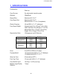
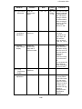
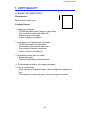
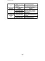
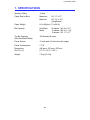
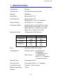
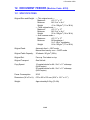
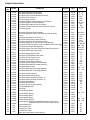
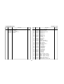
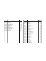
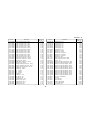
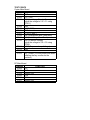
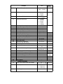
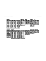
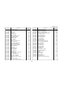
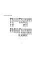
1. SPECIFICATIONS
Configuration:
Desk top
Copy Process:
Dry electrostatic transfer system
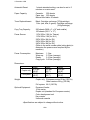
Originals:
Sheet/Book
Original Size:
Maximum A3/11"x17"
Copy Paper Size:
Maximum A3/11"x17"
Minimum A6/5 1/2" x 8 1/2" (lengthwise)
(Duplex Copying)
A4 and B5/8 1/2" x 11" (sideways)
Copy Paper Weight:
Cassette feed: 52 to 157 g/m2 (14 to 42 lb)
Paper tray feed: 64 to 90 g/m2 (17 to 22 Ib)
Manual feed: 52 to 157 g/m2 (14 to 42 lb)
Duplex: 59 to 104 g/m2 (16 to 27 lb)
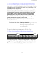
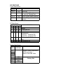
Reproduction Ratio:
2 Enlargement and 3 Reduction
Enlargement
Full size
Reduction
A4/A3 Version
141%
122%
100%
93%
82%
71%
LT/LDG Version
155%
129%
100%
93%
74%
65%
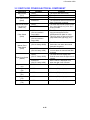
Zoom:
From 50% to 200% in 1% steps
Copying Speed:
18 copies/minute (A4/8 1/2" x 11" sideways)
10 copies/minute (A3/11" x 17")
Warm-Up Time:
60 seconds (at 20oC)
First Copy Time:
5.9 seconds (A4/8 1/2" x 11" sideways)
Copy Number Input:
Ten keys, 1 to 99 (count up)
Manual Image Density
Selection:
7 steps
1-1
1 December 1990
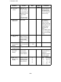
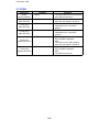
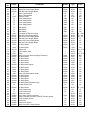
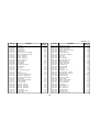
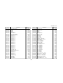
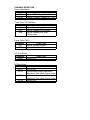
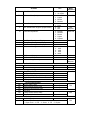
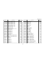
Automatic Reset:
1 minute standard setting; can also be set to 3
minutes or no auto reset.
Paper Capacity:
Cassettes: 500 sheets
Paper tray: 250 sheets
Manual feed table: 50 sheets
Toner Replenishment:
Black: Cartridge exchange (370g/cartridge)
Color (red, blue, & green): Cartridge exchange
(310g/cartridge)
Copy Tray Capacity:
250 sheets (B4/8 1/2" x 14" and smaller)
100 sheets (A3/11" x 17")
Power Source:
110V/ 60Hz/ 15A (for Taiwan)
115V/ 60Hz/ 15A (for N.A.)
220V/ 50Hz/ 8A (for EU.)
220V/ 60Hz/ 8A (for EU.)
240V/ 50Hz/ 8A (for EU.)
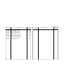
Power Consumption:
(Refer to the serial number plate (rating plate) to
determine the power source required by the
machine.)
Maximum:
1.2 kw
Warm-up:
0.72 kw (average)
Ready:
0.16 kw (average)
Copy cycle:
0.81 kw (average)
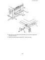
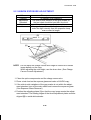
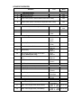
Dimensions:
Copier only
Full system
Width
672 mm
(26.5")
1149 mm
(45.3")
Depth
600 mm
(23.7")
600 mm
(23.7")
Weight:
Copier only: 52 kg (114.7 Ib)
Full system: 71 kg (156.6 Ib)
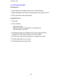
Optional Equipment:
Document feeder
10 bin sorter
Duplex unit
Color development unit
Key counter
Universal Cassette
Height
410 mm
(16.2")
513 mm
(20.2")
•Specifications are Subject to change without notice.
1-2
1 December 1990
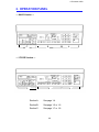
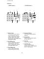
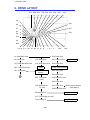
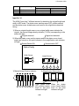
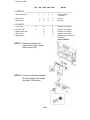
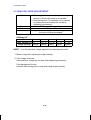
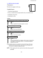
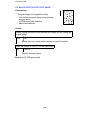
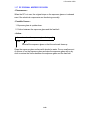
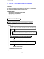
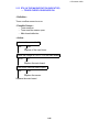
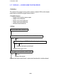
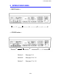
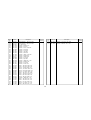
2. OPERATION PANEL
— A4/A3 Version —
C
B
A
— LT/LDG Version —
C
B
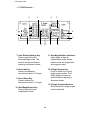
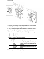
Section A:
See page 1-4.
Section B:
See page 1-5 or 1-6.
Section C:
See page 1-7 or 1-8.
1-3
A
1 December 1990
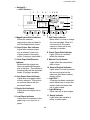
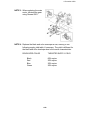
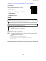
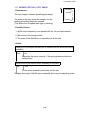
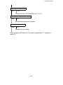
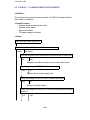
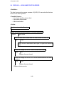
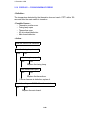
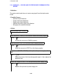
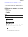
Section A —
— LT/LDG Version —
— A4/A3 Version —
1
2
7
3
1
2
3
4
4
5
5
7
6
6
1. Number Keys
The number keys are used to
enter the desired number of
copies. They are also used to
input the sizes of the original
and the copy image when in size
magnification mode.
4. Interrupt Indicator
Lights when interrupt mode is
selected.
2. Recall/Enter Key
Press to display the number of
copies entered. Also use to
enter or change data when in
size magnification mode.
6. Start Key
Press to start copying.
5. Interrupt Key
Press to make interrupt copies
during a copy run.
7. Clear/Stop Key
Press to cancel the copy
number entered. While copying,
press to stop copying.
3. Clear Modes Key
Press to clear all previously
entered settings and modes.
1-4
1 December 1990
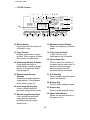
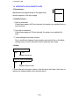
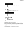
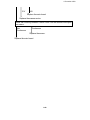
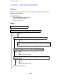
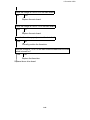
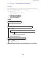
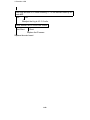
— Section B —
— A4/A3 Version —
1 2
3
4
5 6 7 8 9 10
11
12
13
1
23
22
21
1. Magnification Ratio Indicator
Shows the selected
reproduction ratio and data for
the Size Magnification mode.
2. Check Paper Size Indicator
Lights when improper paper
size is selected in the book
original mode or the duplex
mode. (Copying is impossible.)
14
15
20 19 18
17
16
7. Add Toner Indicator
Blinks when it is time to change
the toner cartridge. When it is
continuously lit, the copier
cannot be used until a new
cartridge is installed.
8. Check Paper Path Indicator
Lights if there is a misfeed
within the machine.
3. Check Paper Size/Direction
Indicator
Blinks when the original size
does not match with the paper
size or direction. This indicator is
functional only with the document
feeder. (Copying is possible.)
9. Manual Feed Indicator
Lights when the manual feed
table is open.
10. Second Original Indicator
Lights when it is time to position
the second original on the
exposure glass when making
duplex copies.
— Light ON —
If copying has been completed,
press duplex key to cancel the
duplex mode and press start
key to eject copies.
— Light Blinking —
Press start key to eject copies.
4. Auto Paper Select Indicator
Lights when auto paper select
mode is selected. This mode is
an optional feature with the
document feeder.
5. Duplex Unit Indicator
Lights when the duplex unit is
installed.
11. Ready Indicator
Lights when the machine is
ready to make copies.
6. Load Paper Indicator
Lights when the cassette or the
paper tray in use runs out of
paper.
1-5
1 December 1990
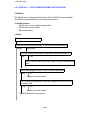
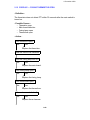
— LT/LDG Version —
1
2
3
4
5 6 7 8 9 10
11
12
13
24
14
15
23
22
21
20 19 18
17
16
12. Wait Indicator
Lights when that the machine is
not ready to copy.
18. Misfeed Location Display
Shows the location(s) of misfed
paper.
13. Copy Counter
Displays the number of copies
entered. While copying, it shows
the number of copies made.
19. Color Copy Indicator
Lights if a color toner
development unit is installed.
20. Select Paper Key
Press to select the cassette or
the paper tray for paper feed, or
press to cancel auto paper
selection mode when the
document feeder is installed.
14. Auto Image Density Indicator
Lights when the copier is
automatically controlling image
density. If this indicator blinks,
refer to page 55.
21. Full Size Key
Press to make copies the same
size as the originals.
15. Manual Image Density
Indicator
Shows the manually selected
image density. If this indicator
blinks, refer to page 55.
22. Enlarge Key
Press to make enlarged copies.
16. Auto Image Density Key
Press to select/cancel the
automatic image density mode.
23. Reduce Key
Press to make reduced copies.
24. Paper Size Indicator
Shows the size and direction of
the paper in use.
17. Manual Image Density Keys
Use to cancel the automatic
image density mode and
manually select the image
density level.
1-6
1 December 1990
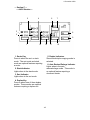
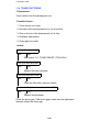
— Section C —
— A4/A3 Version —
5
4
6
7
3
8
2
9
1
13
12
11
10
5. Duplex Indicators
Show which duplex copying mode is
selected.
1. Sorter Key
Press to select the sort or stack
mode. The sort mode and stack
mode are optional features requiring
a sorter.
6. Auto Reduce/Enlarge Indicator
Lights when in the auto
reduce/enlarge mode. This mode is
an optional feature requiring a
document feeder.
2. Stack Indicator
Lights when in the stack mode.
3. Sort Indicator
Lights when in the sort mode.
4. Duplex Key
Press to select one of three duplex
modes. These modes are optional
features requiring a duplex unit.
1-7
1 December 1990
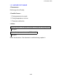
— LT/LDG Version —
5
4
6
7
3
8
2
9
1
13
12
11
10
7. Auto Reduce/Enlarge Key
Press to select the auto
reduce/enlarge mode. This
mode is an optional feature
requiring a document feeder.
11. Size Magnification Indicators
Lights when in the size
magnification mode; shows
when to enter the original size
and copy size data.
8. Zoom Up Key
Press to increase the
reproduction ratio in 1% steps.
12. 2 Single Copies Key
Press to select one of two 2
single copies modes. The 2
Sided Original mode is an
optional feature requiring a
document feeder.
9. Zoom Down Key
Press to reduce the
reproduction ratio in 1% steps.
13. 2 Single Copies Indicators
Show which the 2 single copies
mode is selected.
10. Size Magnification Key
Press to select the size
magnification mode.
1-8
1 December 1990
1-9
1 December 1990
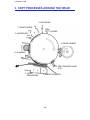
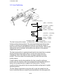
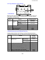
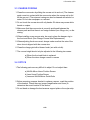
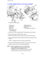
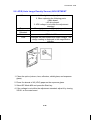
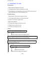
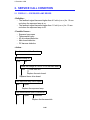
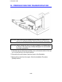
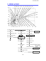
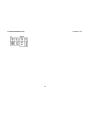
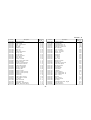
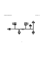
3. COPY PROCESSES AROUND THE DRUM
2. EXPOSURE
1. DRUM CHARGE
3. ERASE
9. QUENCHING
4. DEVELOPMENT
8. CLEANING
5. PRE-TRANSFER LAMP
(PTL)
7. PAPER
SEPARATION
6. IMAGE TRANSFER
1-10
1 December 1990
1. DRUM CHARGE
In the dark, the charge corona unit gives a uniform negative charge to the organic
photoconductive (OPC) drum. The charge remains on the surface of the drum because the
OPC drum has a high electrical resistance in the dark.
2. EXPOSURE
An image of the original is reflected to the OPC drum surface via the optics assembly. The
charge on the drum surface is dissipated in direct proportion to the intensity of the reflected
light, thus producing an electrical latent image on the drum surface.
3. ERASE
The erase lamp illuminates the areas of the charged drum surface that will not be used for
the copy image. The resistance of the drum in the illuminated areas drops and the charge on
those areas dissipates.
4. DEVELOPMENT
Positively charged toner is attracted to the negatively charged areas of the drum, thus
developing the latent image. (The positive triboelectric charge is caused by friction between
the carrier and toner particles.)
5. PRE-TRANSFER LAMP (PTL)
The PTL illuminates the drum to remove all negative charge from the exposed areas of the
drum. This prevents the toner particles from being reattracted to the drum surface during
paper separation and makes paper separation easier.
6. IMAGE TRANSFER
Paper is fed to the drum surface at the proper time so as to align the copy paper and the
developed image on the drum surface. Then, a strong negative charge is applied to the back
side of the copy paper, producing an electrical force which pulls the toner particles from the
drum surface to the copy paper. At the same time, the copy paper is electrically attracted to
the drum surface.
7. PAPER SEPARATION
A strong ac corona discharge is applied to the back side of the copy paper, reducing the
negative charge on the copy paper and breaking the electrical attraction between the paper
and the drum. Then, the stiffness of the copy paper causes it to separate from the drum
surface. The pick-off pawls help to separate paper.
8. CLEANING
The cleaning brush removes most of the toner on the drum and loosens the remainder. Then
the cleaning blade scrapes off the loosened toner.
9. QUENCHING
Light from the quenching lamp electrically neutralizes the surface of the drum.
1-11
1 December 1990
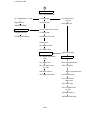
4. FUNCTIONAL OPERATION
1-12
1 December 1990
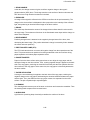
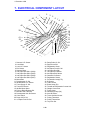
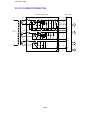
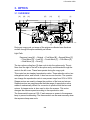
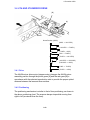
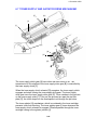
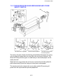
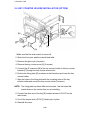
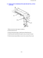
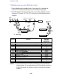
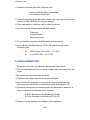
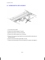
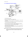
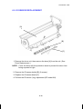
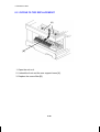
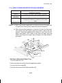
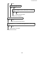
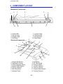
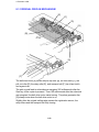
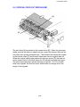
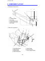
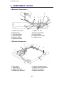
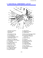
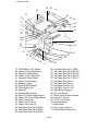
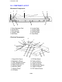
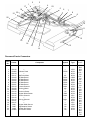
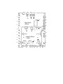
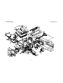
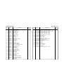
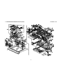
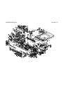
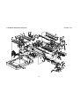
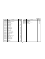
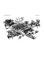
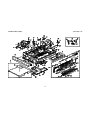
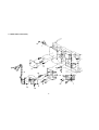
5. MECHANICAL COMPONENT LAYOUT
1
2
3
4
5
6
7
8
9
10
11
12
13 14
15
16
33
17
32
18
31
30
19
29
28
27
26
25
24
23 22
21
20
19. Separation Roller
20. Relay Rollers
21. Semi-circular Feed Rollers
22. Registration Rollers
23. Pre-transfer Lamp (PTL)
24. Transfer and Separation Corona
Unit
25. Pick-off Pawls
26. Cleaning Brush
27. Cleaning Blade
28. Pressure Roller
29. Hot Roller
30. Duplex Turn Guide (Option)
31. Exit Rollers
32. Hot Roller Strippers
33. Exhaust Blower
1. Third Mirror
2. Second Mirror
3. First Mirror
4. Exposure Lamp
5. Ozone Filter
6. Cleaning Unit
7. Lens
8. Quenching Lamp (QL)
9. Charge Corona Unit
10. Sixth Mirror
11. Erase lamp (EL)
12. OPC Drum
13. Development Unit
14. Toner Supply Unit
15. Optics Cooling Fans
16. Feed Roller
17. Manual Feed Table
18. Pick-up Roller
1-13
1 December 1990
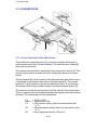
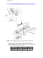
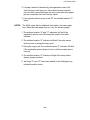
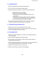
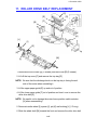
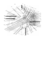
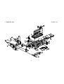
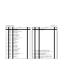
6. DRIVE LAYOUT
G17 BP2 G16
TB1 G19 G18
G22
G23
G24
G5
G6
G26
G7
G27
G9
G28
G8
G10
G4
BP3
G13 G12 G11 G14 G15 BP1G3 G2
G1
G20 G21
G1: Main Motor Gear
G25
G29
G20: Relay Gear
G2: Relay Gear
G18: Relay Gear
G21: Cleaning Drive
G3: Timing Belt Drive Gear
G19: Drum Drive Gear
G22: Relay Gear
BP1: Timing Belt Pulley
TB1: Timing Belt
Drum
Cleaning Unit
Fusing and Exit Section
Development
Section
G23: Relay Gear
G24: Relay Gear
A
BP2: Timing Belt
Pulley
G25: Hot Roller Gear
G26: Relay Gear
G16: Development
CL Gear
G27: Relay Gear
G29: Duplex Transport
Gear (Option)
G28: Exit Roller Gear
Development CL
Development Unit
G17: Toner Supply CL Gear
Toner Supply CL
1-14
Toner Supply Unit
1 December 1990
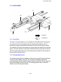
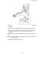
A
Paper Feed Section
BP3: Timing Belt Pulley
G11: Registration CL Gear
G4: Relay Gear
2nd Feed Station
Registration CL
G5: Relay Gear
G12: Relay Roller
CL Gear
1st Paper Feed CL
G6: 1st Paper Feed CL Gear
Relay Roller CL
1st Paper Feed CL
G7: Relay Gear
1st Paper Feed Rollers
G8: Paper Lift CL Gear
Relay Roller
G13: Relay Roller Gear
G14: Relay Gear
Registration Roller
Paper Lift CL
G9: Paper Lift Gear
G10: Sector Gear
1-15
G15: 2nd Paper Feed
CL Gear
2nd Paper Feed CL
2nd Paper Feed Roller
1 December 1990
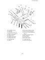
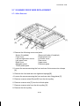
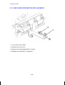
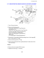
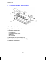
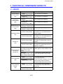
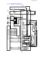
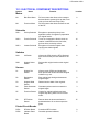
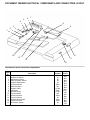
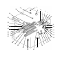
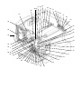
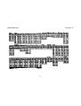
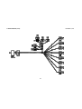
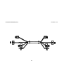
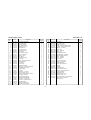
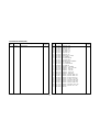
7. ELECTRICAL COMPONENT LAYOUT
43
4
1
2
3
5
6
42
8
10
9
13
11
12
15
16
14
17
18
40
39
41
32
38
36
37
7
34
35 31
30
29 26
33
19
20
22 21
25
24
23
27
28
1. Scanner H.P. Sensor
2. Lens Motor
3. Lens H.P. Sensor
4. Exit Sensor
5. Scanner Motor
6. 2nd Paper Size SW-1 (SW4)
7. 2nd Paper Size SW-2 (SW5)
8. 2nd Paper Size SW-3 (SW6)
9. 2nd Paper Size SW-4 (SW7)
10. Main Motor
11. Development CL Sol.
12. 4th/5th Mirror H.P. Sensor
13. Toner Supply CL Sol.
14. Toner End Sensor
15. 4th/5th Mirror Motor
16. Pick-up Roller Release Sol.
17. Manual Feed Table SW
18. Development Unit Set Sensor
19. Color Switch
20. Paper Lift CL Sol.
21. 1st Paper Feed CL Sol.
22. Relay Roller CL Sol.
23. Right Cover SW
24. Registration Clutch
25. 2nd Paper Feed CL Sol.
26. 1st Paper Size SW
27. 1st Paper End Sensor
28. 2nd Paper End Sensor
29. Cassette Lift Sensor
30. Registration Sensor
31. Pre-transfer Lamp (PTL)
32. ID Sensor
33. Total Counter
34. Erase Lamp (EL)
35. Transfer and Separation Corona Unit
36. Charge Corona Unit
37. Fusing Lamp
38. Quenching Lamp (QL)
39. Auto ID Sensor
40. Toner Overflow Sensor
41. Fusing Thermistor
42. Fusing Thermofuse
43. Tray Lock Sol.
1-16
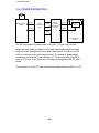
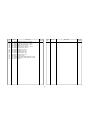
1 December 1990
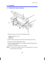
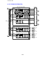
49
50
48
51
47
52
46
53
45
44
62
54
61
55
60
56
59
57
58
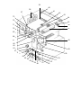
44. Key Counter (Option)
45. Main Board
46. CC/Grid/Bias Power Pack
47. Optics Cooling Fan Motors
48. Optics Thermoswitch
49. Exposure Lamp
50. Operation Panel Board
51. Exhaust Blower Motor
52. Cover Safety SW
53. Main SW
54. Drum Anti-condensation Heater
55. Main DC Power Supply Board
56. Optional DC Power Supply Board
(Option)
57. Optional Transformer (Option)
58. Main Transformer
59. AC Drive Board
60. Main Motor Capacitor
61. TC/SC Power Pack
62. Interface Board (Option)
1-17
1 December 1990
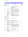
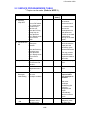
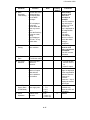
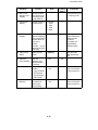
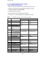
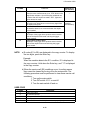
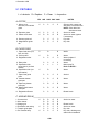
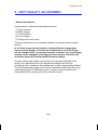
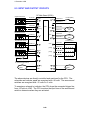
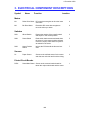
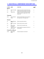
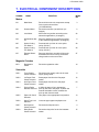
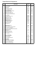
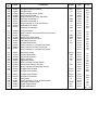
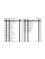
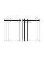
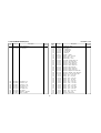
8. ELECTRICAL COMPONENT DESCRIPTIONS
SYMBOL
NAME
FUNCTION
INDEX
NO.
Motors
10
M1
Main Motor
Drives all the main unit components except
for the optics unit and fans.
(115/220/240Vac)
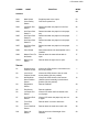
M2
Scanner Motor
Drives the scanners (1st and 2nd). (dc
stepper)
5
M3
Lens Motor
Moves the lens position according to the
selected magnification. (dc stepper)
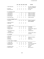
2
M4
4th/5th Mirror Motor
Move the 4th/5th mirror position according
to the selected magnification. (dc stepper)
15
M5
Optics Cooling
Fan Motor-1
Prevents built up of hot air in the optics
cavity. (24 Vdc)
47
M6
Optics Cooling
Fan Motor-2
Prevents built up of hot air in the optics
cavity. (24 Vdc)
47
M7
Exhaust Blower
Motor
Removes heat from around the fusing unit
and blower the ozone built up around the
charge section to the ozone filter.
51
Registration
Clutch
Drives the registration roller.
24
SOL1
Toner Supply
Clutch Solenoid
Drives the toner supply roller via the toner
supply spring clutch.
13
SOL2
1st Paper Feed
Clutch Solenoid
Starts paper feed from the first paper
station.
21
SOL3
2nd Paper Feed
Clutch Solenoid
Starts paper feed from the 2nd paper
station.
25
SOL4
Pick-up Roller
Release Solenoid
a) After the paper is fed, releases the
pick-up roller from next paper. b) When the
manual feed table is used, releases the
pick-up roller from the table.
16
SOL5
Paper Lift Clutch
Solenoid
Lifts paper to the appropriate feed position.
20
SOL6
Tray Lock Solenoid
Locks the paper tray/duplex unit.
43
SOL7
Development
Clutch Solenoid
Drives the development unit.
11
SOL8
Relay Roller
Clutch Solenoid
Drives the relay roller for the 2nd cassette
station.
22
Magnetic Clutch
MC1
Solenoid
1-18
1 December 1990
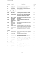
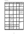
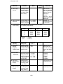
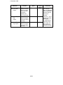
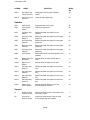
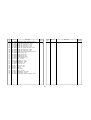
SYMBOL
NAME
FUNCTION
INDEX
NO.
Switches
SW1
Main Switch
Supplies power to the copier.
53
SW2
Cover Safety
Switch
Cuts the ac power line.
52
SW3
1st Paper Size
Switch
Determines what size paper is in the first
cassette.
26
SW4
2nd Paper Size
Switch-1
Determines what size paper is in the paper
tray.
6
SW5
2nd Paper Size
Switch-2
Determines what size paper is in the paper
tray.
7
SW6
2nd Paper Size
Switch-3
Determines what size paper is in the paper
tray.
8
SW7
2nd Paper Size
Switch-4
Determines what size paper is in the paper
tray.
9
SW8
Color Switch
Determines which color development unit is
installed.
19
SW9
Manual Feed Table Switch
Detects when the manual feed table is
open.
17
SW10
Right Cover
Switch
Detects when the right cover is open.
23
S1
Scanner Home
Position Sensor
Informs the CPU when the 1st scanner is at
the home position.
1
S2
Lens Home
Position Sensor
Informs the CPU when the lens is at the
home position (full size position).
3
S3
4th/5th Mirror
Home Position
Sensor
Informs the CPU when the 3rd scanner
(4th/5th mirrors assembly) is at the home
position (full size position).
12
S4
Registration
Sensor
Detects misfeeds.
30
S5
Exit Sensor
Detects misfeeds.
4
S6
1st Paper End
Sensor
Informs CPU when the first cassette runs
out of paper.
27
S7
2nd Paper End
Sensor
Informs CPU when the paper tray runs out
of paper.
28
S8
Toner End
Sensor
Detects when it is time to add toner.
18
S9
Toner Overflow
Sensor
Detects when the used toner tank is full.
40
S10
Paper Lift
Sensor
Detects the correct feed height of the
cassette.
29
Sensor
1-19
1 December 1990
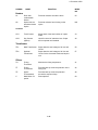
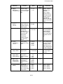
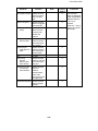
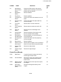
SYMBOL
NAME
FUNCTION
INDEX
NO.
S11
Image Density
(ID) Sensor
Detects the density of the image on the
drum to control the toner density.
32
S12
Development
Unit Set Sensor
Sensors whether or not the development
unit is properly set.
18
Printed Circuit Board
PCB1
Main Board
Controls all copier functions both directly
and through the other PCBs.
45
PCB2
AC Drive Board
Drives all ac motors, the exposure lamp,
fusing lamp, quenching lamp, exhaust
blower motor.
59
PCB3
Main DC Power
Supply Board
Rectifies 26 and 10 Vac input and outputs
dc voltages.
55
PCB4
Auto Image
Density Sensor
(ADS)
Senses the background density of the
original.
39
PCB5
Optional DC
Power Supply
Board
Rectifies 26 and 10 Vac input and outputs
dc voltasges.
56
PCB6
Interface Board
Interfaces between the copier main board
and all the optional equipment’s main board.
62
PCB7
Operation Panel
Board
Informs the CPU of the selected modes
and displays the situations on the panel.
50
L1
Exposure Lamp
Applies high intensity light to the original for
exposure.
49
L2
Fusing Lamp
Provides heat to the hot roller.
37
L3
Quenching Lamp
Neutralizes any charge remaining on the
drum surface after cleaning.
38
L4
Erase Lamp
Discharge the drum outside of the image
area. Provides leading/trailing edge erase.
34
L5
Pre-transfer
Lamp
Reduces charge on the drum surface
before transfer.
31
Lamps
Power Packs
P1
CC/Grid/Bias
Power Pack
Provides high voltage for the charge
corona, grid, and the development roller
bias.
46
P2
TC/SC Power
Pack
Provides high voltage for the transfer and
separation corona.
61
1-20
1 December 1990
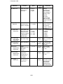
SYMBOL
NAME
FUNCTION
INDEX
NO.
Heaters
H1
Drum Anticondensation
Heater
Prevents moisture around the drum.
54
H2
Optics Anti-condensation Heater
Option
Prevents moisture from forming on the
optics.
N/A
CO1
Total Counter
Keeps track of the total number of copies
made.
33
CO2
Key Counter
(Option)
Used for control of authorized use. Copier
will not operate until installed.
44
Counters
Transformer
TR1
Main Transformer
Steps down the wall voltage to 26 Vac and
10 Vac.
58
TR2
Optional
Transformer
Steps down the wall voltage to 26 Vac and
10 Vac for the document feeder and duplex
unit.
57
TH
Fusing
Thermistor
Monitors the fusing temperature.
41
TF
Fusing
Thermofuse
Provides back-up overheat protection in the
fusing unit.
42
TS
Optics
Thermoswitch
Provides back-up overheat protection
around the exposure lamp.
48
C
Main Motor Capacitor
Start capacitor
60
Others
1-21
1 December 1990
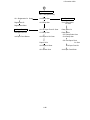
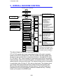
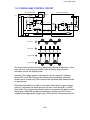
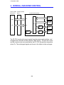
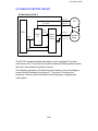
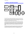
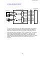
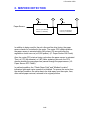
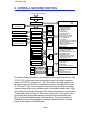
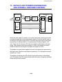
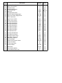
9. OVERALL MACHINE CONTROL
AC Power (115V or 220/240V)
Cover Safety Switch
Anti-condensation Heater
-Drum
-Optics
Main Switch
Operation
Panel Board
IC 123
CPU
AC Drive Board
Exhaust Blower Motor (L)
Power Relay
Fusing Lamp
Fusing Lamp
Drive Circuit
Exposure Lamp
Exposure Lamp
Drive Circuit
IC 124
I/O
Main Motor
Quenching Lamp
Exhaust Blower Motor (H)
Main Motor Relay
IC 111
ROM
IC 105
I/O
Power Packs
CC/Grid/Bias P.P.
Charge Corona
Grid Voltage
Dev. Bias
Main Board
RAM
Board
TC/SC P.P.
Total Counter
Key Counter
Duplex
Solenoids/Clutches
Pick-up Roller Release Sol.
Cassette Lift CL Sol.
1st/2nd Paper Feed CL Sol.
Relay Roller CL Sol.
Registration Clutch
Tray Lock Sol.
Development Drive CL Sol.
Toner Supply CL Sol.
Motors
Scanner Motor
Lens Motor
4th/5th Mirror
Optics Cooling Fan Motor
Counters
ARDF
Sensors/Switches/Thermistor
Image Density Sensor
Registration Sensor
Cassette Lift Sensor
Exit Sensor
Auto ID Sensor
Scanner HP Sensor
Lens HP Sensor
4th/5th Mirror HP Sensor
Toner Overflow Sensor
Toner End Sensor
Color Switch
1st/2nd Paper Size Switches
1st/2nd Paper End Sensors
Right Cover Switch
Manual Feed Table Switch
Fusing Thermistor
Serial
Serial
Sorter
Interface
Board
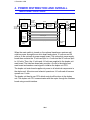
NOTE: The interface board is
connected to the copier main
board when the ARDF, duplex
unit and/or sorter is installed.
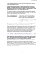
The above diagram shows the control system of this copier in block form. The
CPU (IC123) on the main board controls the timing of all copier’s operation
based on the CPU’s internal clock. The CPU monitors the input signals from
all sensors and controls the dc components directly or through two I/O chips
(IC 105 and IC 124). It also controls ac components such as the fusing lamp,
exposure lamp, main motor quenching lamp, and exhaust blower motor (High
speed) directly via the ac drive board. The exhaust blower motor (Low speed)
is controlled via the I/O chip (IC 124) and ac drive board. The charge corona,
grid voltage and development bias are powered by the same power pack
(P1) but are controlled separately as shown above. The main board has a
RAM board for the service program mode and misfeed recovery. A battery
backs up the power to the RAM board.
1-22
1 December 1990
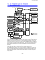
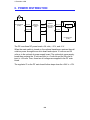
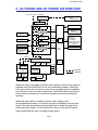
10. AC POWER AND DC POWER
DISTRIBUTION
AC Power (115V or 220/240V)
Anti-condensation Heater
-Drum
-Optics (Option)
Main SW
Cover Safety SW
Scan Operation Panel Board
Signal
Fuse
24V (VA)
5V (VC)
Fusing Lamp
Drive Circuit
24V (VA)
Exposure Lamp
Drive Circuit
24V (VA)
Solenoids
Clutches
Packs
24V (VA) Power
Lens Motor
4th/5th Mirror Motor
Optics Cooling Fan
Motors
Main Motor
Relay (RA402)
24V (VA)
Exhaust Blower
Motor (L)
Fusing Lamp
RAM
PCB
Exposure Lamp
Main Motor
Quenching Lamp
Exhaust Blower
Motor (H)
Sensors
Switches
Interface Board
Power Relay
(RA401)
30V (VM)
Main
Board
Scanner Motor
AC Drive Board
Optional Transformer
26V AC 10V AC
FU100 (5V)
FU101 (24V)
Optional
DC Power Supply
Board
10V AC
26V AC
30V (VM)
Main DC Power Supply Board 24V (VA)
24V 5V 24V 5V
(VA) (VC) (VA) (VC)
ARDF
Interface
Board
Main Transformer
26V AC
5V (VC)
FU100 (5V)
FU101 (24V)
FU102 (30V)
Zero
Cross
Duplex
Sorter
ac power
dc power
24V (VA)
5V (VC)
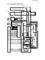
When this copier is plugged in and the main switch is turned off, ac power is
supplied via the ac drive board to the anti-condensation heater. When the
front cover and/or the exit cover is open, the cover safety switch completely
cuts off power to all ac and dc components. The RAM board has a back up
power supply (dc battery) for the service program mode and misfeed job
recovery.
When the main switch is turned on, the ac power supply to the
anti-condensation heater is cut off and ac power is supplied to the ac drive
board. The main transformer receives wall outlet ac power through the ac
drive board and outputs 10 volts ac and 26 volts ac to the main dc power
supply board.
1-23
1 December 1990
The main dc power supply board converts the 10 volts ac input to +5 volts
and a zero cross signal. There are two 26 volts ac inputs. The dc power
supply board converts them to +24 volts and +30 volts.
The +5 volts and +24 volts are supplied to both the copier main board and
the sorter main board. The zero cross signal and +30 volts are supplied to
the copier main board.
The copier main board supplies dc powers to all copier dc components. All
sensors, and switches plus the interface board operate on +5 volts. The
scanner motor operates on +30 volts. All other dc components including the
power relay (RA401) and the main motor relay (RA402) operate on +24 volts.
The ARDF and the duplex unit have a separate dc power supply.
When the main board receives power, it activates the power relay (RA401)
which then supplies ac power to the fusing lamp drive circuit, and the
exposure lamp drive circuit on the ac drive board. The exhaust blower motor
begins rotating at low speed. The fusing lamp drive circuit receives a trigger
signal from the main board and the fusing lamp lights. The exposure lamp
does not turn on until the main board send a trigger pulse to the exposure
lamp drive circuit.
When the Start key is pressed, the main board energizes the main motor
relay (RA402). Then, the main motor and the quenching lamp turn on and the
exhaust blower starts rotating at high speed.
When the main switch is turned off, power is cut off to the main board and to
RA401, and the drum and optional anticondensation heaters are turned on.
The exposure lamp and the fusing lamp power lines are completely
disconnected from the line voltage.
1-24
1 December 1990
10.1 AC POWER DISTRIBUTION
Main SW
(SW1)
T403
115V
220/240V
T402
T401
T404
Cover
Safety
SW (SW2)
CN411-1
RA402-1
Fuse
T407
CN411-2
Drum
Anti-condensation
Heater (H1)
To DF and Duplex
Optional
DC Power
Supply
Board
(PCB5)
[24] VA
[5] VC
[0] GND
10V AC TR2 CN418-1
CN418-3
26V AC
To Sorter
[24] VA
[5] VC
[0] GND
CN103-1
CN103-2
CN103-3
TR1
ZERO
CROSS
[0] GND
[0] GND
[30] GND
[0] GND
[24] VA
[0] GND
[5] VC
Main
RA402-2
CN417-3
CN417-1
CN108-1
CN108-2
CN107-1
CN107-2
CN107-3
CN107-4
CN107-5
CN107-6
CN100-1
CN100-2
CN100-3
CN100-4
CN100-5
CN100-6
CN102-2
CN102-1
CN101-1
CN101-2
CN101-3
CN101-4
CN101-5
CN101-6
RA401
10V AC
DC
Power
Supply
Board
(PCB3)
Board
(PCB1)
CN122-10
CN401-5
CN122-14
CN122-9
CN401-1
CN401-6
CN122-13
CN122-12
CN122-11
AC
Drive
Board
(PCB2)
26V AC
CN401-8
CN401-9
CN420-2
Exhaust Blower Motor
CN419-1
Exposure Lamp
T405
Fusing
Lamp
26V AC
CN122-7
CN122-6
CN420-3
Noise Filter
Circuit
(220/240V
Only)
Exposure
Lamp Drive
Circuit CN421
(220/240V
Only)
Fusing
Lamp Drive
Circuit
CN401-2
CN401-3
Power Relay
RA401
RA402
Main Motor Relay
CN401-4
1-25
Thermofuse
169o C
(TF)
H
Thermoswitch
(TS)
L
M
(L2) (L1)
CN413-1
Main
Motor (M1)
CN415-1
M
Quenching
Lamp
(L3)
CN415-2
CN413-2
T406
CN419-2
CN420-1
(M7)
1 December 1990
10.2 DC POWER DISTRIBUTION
DC Power Supply Board
CN417
-1
CN100
-5
FU100
ST100
Main Board
R100 Q100
D102
D100
R103
10VAC
IC100
ON
CN100
-6
D101
+
+
C100
C101
D103
+
C103 C104
C112
R101
R102
R104
R105
C105
R106
115V
220/240V
CN100
-3
Q101
FU101
ST101
R107
Q102
D104
26VAC
IC101
CN100
-1
+
+
C110
C107
C108 C109 D105
FU102
ST102
CN107
-6
CN101
-5
CN107
-5
CN102
-1
CN108
-2
CN101
-4
CN107
-4
[5]Vc
To
CN103
( Sorter
)
-2
CN108
CN102
-2
-1
Zero
Cross
To
CN103
( Sorter
)
-1
CN103
To
( Sorter
-3
+
CN100
-4
CN101
-6
[0]GND
[0]GND
[24]VA
-3
CN100
-2
[5]VC
)
C113
CN101
-3
CN107
-3
CN101
-2
CN107
-2
[0]GND
[30]VM
26VAC
CN417
[24]VA
[30]VM
+
C110
R108 C111 C114
CN101
-1
CN107
-1
[0]GND
[0]GND
1-26
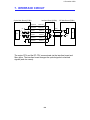
SECTION 2
SECTIONAL DESCRIPTION
1 December 1990
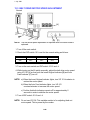
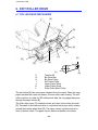
1. DRUM
1.1 OPC DRUM CHARACTERISTICS
An OPC has the characteristics of:
1. Being able to accept a high negative electrical charge in the dark. (The
electrical resistance of a photoconductor is high in the absence of light.)
2. Dissipating the electrical charge when exposed to light. (Exposure to light
greatly increases the conductivity of a photoconductor.)
3. Dissipating an amount of charge in direct proportion to the intensity of the
light. That is, where stronger light is directed to the photoconductor
surface, a smaller voltage remains on the OPC.
4. Being less sensitive to changes in temperature (when compared to
selenium F type drums). This makes it unnecessary to monitor and
control the drum temperature.
2-1
1 December 1990
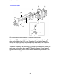
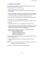
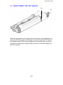
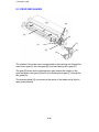
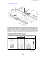
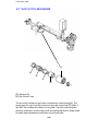
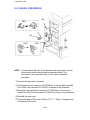
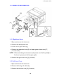
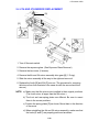
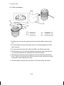
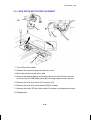
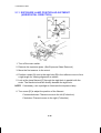
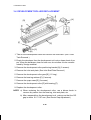
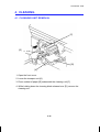
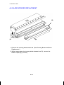
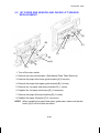
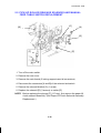
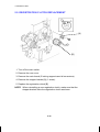
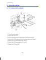
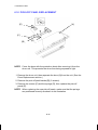
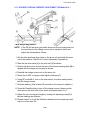
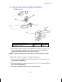
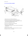
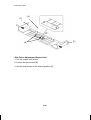
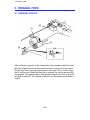
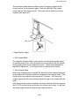
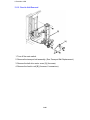
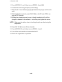
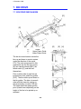
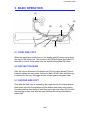
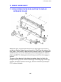
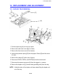
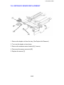
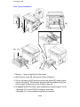
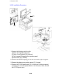
1.2 DRUM UNIT
[F]
[H]
[G]
[B]
[E]
[C]
[A]
[C]
[D]
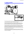
An organic photoconductor drum [A] is used on this model.
A drum unit [B] is used to hold the drum to prevent stress on the drum. The
drum unit consists of an OPC drum, ID sensor [C] and pick-off pawls [D].
When the drum is replaced, and/or the pick-off pawls and/or the ID sensor
are cleaned, the drum unit must be removed from the copier as a unit.
The drum is driven by the main motor [H] through the main motor gear [E], a
relay gear and the drum drive gear [F]. The pick-off pawls [D] are always in
contact with the drum surface. The ID sensor is electrically connected to the
ID sensor connector [G].
2-2
1 December 1990
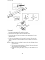
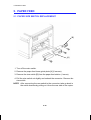
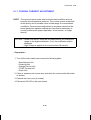
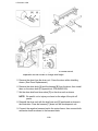
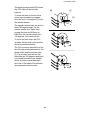
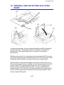
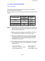
1.3 HANDLING THE DRUM
The organic photoconductor drum is comparatively more sensitive to light
and ammonia gas than a selenium drum.
1. Never expose the drum to direct sunlight.
2. Never expose the drum to direct light of more than 1,000 Lux for more
than a minute.
3. Never touch the drum surface with bare hands. When the drum surface is
touched with a finger or becomes dirty, wipe with a dry cloth or clean with
wet cotton. Wipe with a dry cloth after cleaning with wet cotton.
4. Never use alcohol to clean the drum; alcohol dissolves the drum surface.
5. Store the drum in a cool, dry place away from heat.
6. Take care not to scratch the drum as the drum layer is thin and is easily
damaged.
7. Never expose the drum to corrosive gases such as ammonia gas.
8. Always keep the drum in the protective sheet when inserting or pulling the
drum unit out of the copier to avoid exposing it to bright light or direct
sunlight. This will protect the drum from light fatigue.
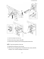
9. Before inserting or pulling out the drum unit, the following should be
performed to avoid damaging the drum:
a) Remove the cleaning unit.
b) Remove the development unit.
c) Remove the charge corona unit.
d) Release the transport unit.
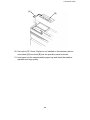
10. Before pulling out the drum unit, place a sheet of paper under the drum to
catch any dropped toner.
11. Drum initial setting (SP #66) must be performed when a new drum is
installed.
NOTE: This is not necessary at installation of a new machine as the drum
initial setting is performed at the factory.
12. Dispose of the used drum according to local regulations.
2-3
1 December 1990
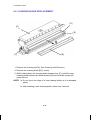
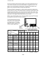
2. DRUM CHARGE
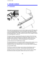
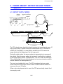
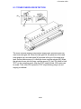
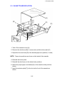
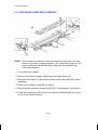
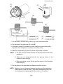
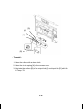
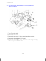
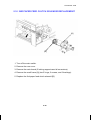
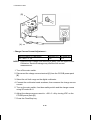
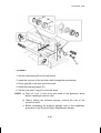
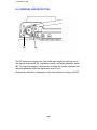
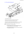
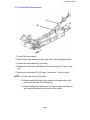
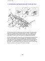
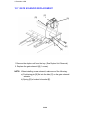
2.1 OVERVIEW
[C]
[A]
[C]
[B]
[A]
This copier uses a single wire scorotron and a highly sensitive OPC drum [A].
The corona wire [B] generates a corona of negative ions when the CC/B/G
power pack applies a high voltage. A stainless steel grid plate [C] makes the
corona charge uniform. The drum coating receives a uniform negative charge
as it rotates past the corona unit.
The exhaust blower, located above the copy exit, causes a flow of air from
the upper area of the development unit through the charge corona unit. This
prevents uneven build-up of negative ions that can cause uneven image
density. The exhaust blower runs at half speed when in the stand-by
condition and runs at full speed while copying.
The exhaust blower has an ozone filter (active carbons) which adsorbs ozone
(O3) generated by the corona discharge. The ozone filter decreases in
efficiency over time as it adsorbs ozone. The ozone filter should be replaced
at every 60,000 copies.
The flow of air around the charge corona wire may deposit paper dust or
toner particles on the corona wire. These particles may interfere with
charging and cause low density bands on copies. The wire cleaner cleans
the corona wire when the operator slides the corona unit in and out.
2-4
1 December 1990
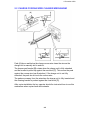
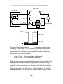
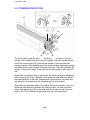
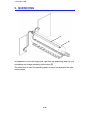
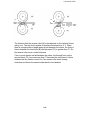
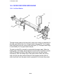
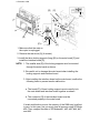
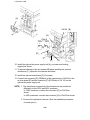
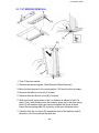
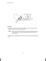
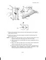
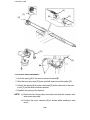
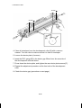
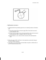
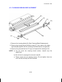
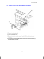
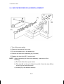
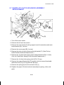
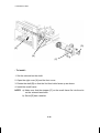
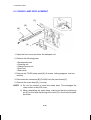
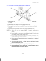
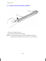
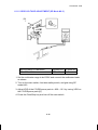
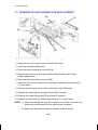
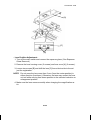
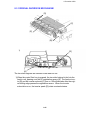
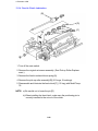
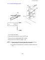
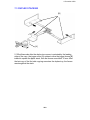
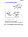
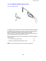
2.2 CHARGE CORONA WIRE CLEANER MECHANISM
[B]
[A]
[D]
[C]
Pads [A] above and below the charge corona wire clean the wire as the
charge unit is manually slid in and out.
The cleaner pad bracket [B] rotates when the charge unit is fully extended
and the bracket is pulled up against the rear block [C]. This moves the pads
against the corona wire (see illustration). If the charge unit is not fully
extended, the pads do not touch the corona wire.
The pads move away from the wire when the charge unit is fully inserted and
the cleaning bracket is pushed against the front block [D].
After copier installation the key operator should be instructed how to use this
mechanism when copies have white streaks.
2-5
1 December 1990
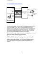
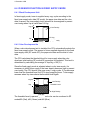
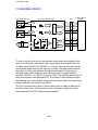
2.3 CHARGE CORONA CIRCUIT
CN112-8
CN1-1
CN112-7
CN1-2
CN112-6
CN1-3
CN112-5
CN1-4
CN112-4
CN1-5
CN112-3
CN1-6
VA [24]
VC [5]
CC Trig [ 24]
Grid Trig (PWM) [
0
0/5]
Grid FB
CN112-2
CN1-7
CN112-1
CN1-8
CC/Grid/Bias
Power Pack
(P1)
TC
Charge
Corona Wire
TG
Grid
TB
Development
Roller
GND [0]
Main Board (PCB 1)
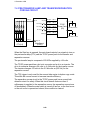
The main board supplies +24 volts to the CC/Grid/Bias power pack at CN1-1
as the power supply source. About 0.44 seconds after the Start key is
pressed, the CPU drops CN1-3 from +24 volts to 0 volts. This energizes the
charge corona circuit within the CC/Grid/Bias power pack, which applies a
high negative voltage of approximately –5.6 kv to the charge corona wire.
The corona wire then generates a negative corona charge.
The grid limits the charge voltage to ensure that the charge does not fluctuate
and an even charge is applied to the drum surface.
The grid trigger pulse applied to CN1-5 is a pulse width modulated signal
(PWM signal). This signal is not only a trigger signal; it also changes the
voltage level of the grid. As the width of the pulse applied increases, the
voltage of the grid also increases. The CPU monitors the grid voltage at
CN1-7 and controls the width of the grid trigger pulses based on this
feedback.
2-6
1 December 1990
2.4 GRID VOLTAGE CORRECTION
There are two grid voltage correction factors. These correct for increases in
the drum residual voltage (Vr). The first such factor, Vr correction, is done
every 1,000 copies. Vr correction is based on the data of the drum counter
(SP #69) and the Vr correction ratio (L) (SP #67). The second factor, Vp
correction, corrects for changes in the photoconductor’s chargeability. (The
chargeability of a new OPC drum may change after installation, but this
stabilizes at around 2,000 copies.) Vp correction is based on the drum
counter. The counter resets to "0" when drum initial setting (SP mode #66) is
performed.
Both correction factors are applied to the copy process as follows:
1. Image area
Grid Voltage = –920 volts
+
Vr Correction Factor.
Vr Correction Factor
L
100 to 89 (%)
88 to 76 (%)
75 to 62 (%)
61 to 45 (%)
44 to 0 (%)
Change of Grid Voltage
±0 (volts)
–40 (volts)
–80 (volts)
–120 (volts)
–160 (volts)
L = Vrp/Vsg x 100 (Vr correction ratio)
Vrp: ID sensor output for Vr correction pattern
Vsg: ID sensor output for bare drum
2. Non-image area
Grid Voltage = 0 volts (Fixed)
2-7
1 December 1990
3. ID sensor pattern area
Grid Voltage = –620 volts
+
Vp Correction Factor
Drum Counter
0 to 999 (copies)
1,000 to 1,999 (copies)
Over 2,000 (copies)
Vp Correction Factor
Black
Color
±0 (volts)
±0 (volts)
–20 (volts)
±0 (volts)
–40 (volts)
–20 (volts)
4. Vr correction pattern area
Grid Voltage = –500 volts (Fixed)
2-8
1 December 1990
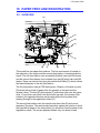
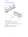
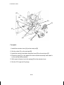
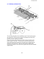
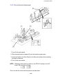
3. OPTICS
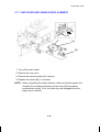
3.1 OVERVIEW
[C]
[B]
[A]
[E]
[D]
[H]
[I]
[F]
[J]
[G]
During the copy cycle, an image of the original is reflected onto the drum
surface through the optics assembly as follows.
Light Path:
Exposure Lamp [A] → Original → First Mirror [B] → Second Mirror [C]
→ Third Mirror [D] → Lens [E] → Fourth Mirror [F] → Fifth Mirror [G]
→ Sixth Mirror [H] → Drum [I]
The two optics cooling fans [J] draw cool air into the optics cavity. The air
flows from the right to the left in the optics cavity and exhausts through the
vents in the left cover. These fans operate during the copy cycle.
This copier has six standard reproduction ratios: Three reduction ratios, two
enlargement ratios, and full size. It also has a zoom function. The operator
can change the reproduction ratio in one percent steps from 50% to 200%.
Stepper motors are used to change the positions of the lens and mirrors.
Separate motors are used because the wide range of reproduction ratios
makes it mechanically difficult for one motor to position both the lens and
mirrors. A stepper motor is also used to drive the scanner. This motor
changes the scanner speed according to the reproduction ratio.
The thermoswitch opens at 130 oC and removes ac power to the exposure
lamp to prevent overheating. The thermoswitch can be reset manually when
the exposure lamp area cools.
2-9
1 December 1990
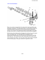
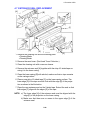
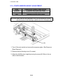
3.2 SCANNER DRIVE
[B]
[D]
[E]
[F]
[C]
[A]
[G]
3.2.1 1st and 2nd Scanner Drive Mechanism
This model uses a stepping motor [A] to drive the scanners. Both ends of
each scanner are driven to prevent skewing. The scanners have sliders [B],
which ride on guide rails.
The scanner home position is detected by the home position sensor [C]. The
scanner return position is determined by counting the scanner motor drive
pulses.
The first scanner [D], which consists of the exposure lamp and the first mirror,
is connected to the scanner drive wire by the wire clamps [E]. The second
scanner [F], which consists of the second and third mirrors, is connected to
the scanner drive wire by movable pulleys (the second scanner pulley [G]).
The pulley moves the second scanner at half the velocity of the first scanner.
This is to maintain the focal distance between the original and the lens during
scanning. This relationship can be expressed as:
V1r
= 2 (V2r) = VD/r
where r = Reproduction ratio
V1r
= First scanner velocity (when the reproduction ratio
is "r")
V2r
= Second scanner velocity (when the reproduction ratio
is "r")
VD
= Drum peripheral velocity (120 mm/s)
2-10
1 December 1990
3.3 LENS DRIVE
[C]
[D]
[E]
[F]
[B]
[G]
[A]
: Reduction
: Enlargement
3.3.1 Lens Drive
The lens motor [A] (stepper motor) changes the lens [B] position through the
lens drive wire [C] in accordance with the selected reproduction ratio to
provide the proper optical distance between the lens and the drum surface.
The rotation of the lens drive pulley moves the lens back and forth in discrete
steps. The home position of the lens is detected by the home position sensor
[D]. The main board keeps track of the lens position based on the number of
pulses sent to the lens motor.
3.3.2 Shading Mechanism
The shading plates [E] are installed on the lens housing [F] and are slid open
and shut by the shading cam [G]. This shading mechanism adjusts the
horizontal light intensity, which becomes uneven in reduction mode, when the
light at both edges is more intense. The shading plates close in reduction
mode to even out the light intensity.
2-11
1 December 1990
3.3.3 Lens Positioning
[A]
[C]
Home Position (100%)
(100% → 141/155%)
[D]
(141/155% → 71/65%)
(71/65% → 93%)
(93% → 71/65%)
(71/65% → 141/155%)
[B]
(141/155% → 122/129%)
(122/129% → 100%)
(100% → 71/65%)
(71/65% → 100%)
Enlargement Side
Reduction Side
The lens home position sensor [A] informs the main board when the lens is at
full size position (home position). The main board determines the lens stop
position in reduction and enlargement modes by counting the number of
steps the motor makes with reference to the lens home position. When a new
reproduction ratio is selected, the lens [B] moves directly to the selected
magnification position.
The lens home position is registered each time the lens starts from or passes
through the lens home position sensor. As the lens moves from the
enlargement side to the reduction side, the sensor registers the home
position. This occurs when the actuator plate [C] enters the lens home
position sensor.
A small vibration can be observed when the lens moves through home
position from the reduction side to the enlargement side because the lens is
going in the wrong direction to register the home position. The lens
overshoots the home position by only one pulse before going back to register
the home position.
The lens always stops while moving from left to right (as viewed from the
front) to minimize the error caused by mechanical play in the drive gears [D].
2-12
1 December 1990
3.4 4TH AND 5TH MIRROR DRIVE
[B]
[A]
Home Position (100%)
(100% → 141/155%)
(141/155% → 71/65%)
(71/65% → 93%)
(93% → 71/65%)
(71/65% → 141/155%)
(141/155% → 122/129%)
(122/129% → 100%)
(100% → 71/65%)
(71/65% → 100%)
3.4.1 Drive
The 4th/5th mirror drive motor (stepper motor) changes the 4th/5th mirror
assembly position through the pinion gears [A] and the rack gear [B] in
accordance with the selected reproduction ratio to provide the proper optical
distance between the lens and drum surface.
3.4.2 Positioning
The positioning mechanism is similar to that of lens positioning, as shown in
the above positioning chart. The scanner always stops while moving from
right to left (as viewed from the front).
2-13
1 December 1990
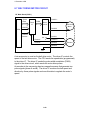
3.5 STEPPER MOTOR CONTROL CIRCUIT
Scanner
H.P. Sensor
(S1)
Lens
H.P. Sensor
(S2)
CN122-3
CN806-3
CN122-4
CN806-2
CN122-5
CN802-1
CN102-7
CN824-3
CN102-8
CN824-2
CN105-1
[0] GND
VM [30]
[ 5]
CN105-2
Scanner H.P. A [ 30 0/30]
CN105-3
[5] VC
A [ 30 0/30]
CN105-4
B [ 30 0/30]
CN105-5
[0] GND
B [ 30 0/30]
CN105-6
[ 5] Lens H.P.
VM [30]
CN102-9
CN824-1
[5] VC
VA[24]
4th/5th
Mirror
H.P. Sensor
(S3)
A [ 24 0/24]
CN102-10
CN826-3
[0] GND
CN102-11
CN826-2
CN102-12
CN826-1
A [ 24 0/24]
[ 5] 4th/5th
Mirror H.P. B [ 24 0/24]
[5] VC
B [ 24 0/24]
VA[24]
CN102-1
Scanner
Motor
(M2)
CN825
6
1
CN102-2
5
2
CN102-3
4
3
CN102-4
3
4
CN102-5
2
5
CN102-6
1
6
Lens
Motor
(M3)
CN106-1
VA[24]
A [ 24 0/24]
CN106-2
CN106-3
A [ 24 0/24]
4th/5th
Mirror
Motor
(M4)
CN106-4
B [ 24 0/24]
CN106-5
B [ 24 0/24]
CN106-6
VA[24]
Main Board (PCB1)
Step
1
2
3
4
5
6
7
Com.
Com.
1
6
8
ON
A
OFF
ON
B
OFF
ON
A
OFF
ON
B
OFF
2
3
4
5
A
A
B
B
The scanner motor, the lens motor, and the 4th/5th mirror motor are all
stepper motors. The scanner motor operates on +30 volts. Both the lens
motor and the 4th/5th mirror motor operate on +24 volts. The stators of these
stepper motors have four coils (labeled A, B, A, B above), and the rotor is
made of permanent magnets. Pulse signals energize the four coils as shown
in the above illustration. The rotors of these motors turn in discrete steps, and
48 steps are required for one revolution.
2-14
1 December 1990
The lens motor and the 4th/5th mirror motor move at a constant speed, but
the scanner motor speed varies according to the reproduction ratio. The CPU
changes the pulse rate (pulse per second) to adjust the speed for the
selected reproduction ratio.
HP sensors inform the main board when the first scanner, lens, and 4th/5th
mirror assembly reach their respective home positions. The main board
determines the stop position by counting the number of steps the motor
makes with reference to the home position.
2-15
1 December 1990
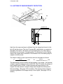
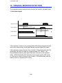
3.6 AUTOMATIC IMAGE DENSITY DETECTION
[A]
[C]
[B]
Sampled area
70 mm
A
B
Light from the exposure lamp is reflected from the original and travels to the
lens [A] via the mirrors. The auto ID sensor [B], a photodiode, is mounted on
the upper front frame. The sensor cover [C] has a hole in it to allow light to
fall directly onto the sensor. Sampling starts 10 millimeters from the leading
edge of the original and continued to 40 millimeters from the leading edge of
original in full size mode.
The length A and B in each reproduction ratio are calculated as follows:
A=
10 mm
Reproduction Ratio (%)
x100
B=
40 mm
Reproduction Ratio (%)
x100
The photosensor circuit converts the light intensity to a voltage. The detected
voltage is amplified and sent to the main PCB. The CPU stores the voltage of
each sampled point in RAM. It then computes the image density of the
original from the maximum sample voltage and changes the development
bias accordingly. (See page 2-30 for details.) The exposure lamp voltage is
constant regardless of the image density of the original. (See page 2-18 for
details.)
2-16
1 December 1990
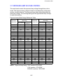
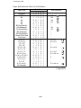
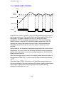
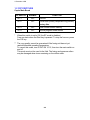
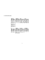
3.7 EXPOSURE LAMP VOLTAGE CONTROL
The main board controls the exposure lamp voltage through the ac drive
board. The exposure lamp voltage is based on the base lamp voltage and
various correction factors. The exposure lamp data setting determines the
base lamp voltage. The following table gives the approximate lamp voltage
for each data setting.
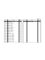
Exposure Lamp Data/Voltage Reference Table
Exposure
Lamp Data
100
101
102
103
104
105
106
107
108
109
110
111
112
113
114
115
116
117
118
119
120
121
122
123
124
125
Exposure Lamp Voltage
(Standard)
220/240V
115V machine
machine
57.1
105.9
57.6
106.9
58.2
108.0
58.8
109.1
59.3
110.1
59.9
111.2
60.5
112.2
61.1
113.3
61.6
114.4
62.2
115.4
62.8
116.5
63.3
117.5
63.9
118.6
64.5
119.6
65.0
120.7
65.6
121.8
66.2
122.8
66.8
123.9
67.3
124.9
67.9
126.0
68.5
127.1
69.0
128.1
69.6
129.2
70.2
130.2
70.8
131.3
71.3
132.4
Exposure
Lamp Data
126
127
128
129
130
131
132
133
134
135
136
137
138
139
140
141
142
143
144
145
146
147
148
149
150
Exposure Lamp Voltage
(Standard)
220/240V
115V machine
machine
71.9
133.4
72.5
134.5
73.0
135.5
73.6
136.6
74.2
137.6
74.7
138.7
75.3
139.8
75.9
140.8
76.5
141.9
77.0
142.9
77.6
144.0
78.2
145.1
78.7
146.1
79.3
147.2
79.9
148.2
80.5
149.3
81.0
150.4
81.6
151.4
82.2
152.5
82.7
153.5
83.3
154.6
83.9
155.6
84.4
156.7
85.0
157.8
85.6
158.8
NOTE: Exposure lamp rating: 100V machine: 85V/300W
115V machine: 97V/300W
220/240V machine: 180V/330W
2-17
1 December 1990
The exposure lamp voltage consists of the following 3 factors:
Exposure lamp voltage = Base lamp voltage factor
+
Reproduction ratio correction factor
+
Drum wear correction factor
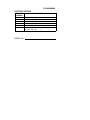
3.7.1 Base Lamp Voltage Factor In Manual Image Density Control
Darker
Manual ID Level
Exposure Lamp Data
Lighter
1
Vo –4
2
Vo ±0
3
Vo ±0
4
Vo ±0
5
Vo +4
6
Vo +8
7
Vo +12
The above table shows changes in the exposure lamp data in manual image
density mode.
SP mode #48 sets the exposure lamp data for level 4 (Vo) of manual image
density mode. A value from 100 to 150 can be selected.
3.7.2 Base Lamp Voltage Factor In Auto Image Density Control
In auto ID mode, the CPU selects the level 4 (Vo) exposure lamp data
regardless of the input from the auto image density sensor. When the auto
image density level is set to lighter in SP mode #34, the exposure lamp data
changes to that of manual ID level 5 as shown below. When the auto image
density level is set to darker, the development bias shifts +40 volts. Only the
development bias varies according to the input from the auto image density
sensor. (See page 2-30).
Auto Image Density Level (SP mode #34)
Auto Image Density
Level
SP Data
(SP mode #34)
Normal
0
Darker
1
Lighter
2
Exposure Lamp Data
Same as level 4
(Vo ±0)
Same as level 4
(Vo ±0)
Same as level 5
(Vo +4)
2-18
Development Bias
Shift
±0 volts
+40 volts
±0 volts
1 December 1990
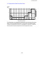
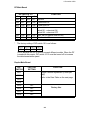
3.7.3 Reproduction Ratio Correction Factor
Exposure
Lamp
Data
+10
Lighter
+5
+0
-
50
62
100
140
150
160
180
200 (%)
Reproduction Ratio
For the reduction and enlargement reproduction ratios the light path is longer
than for the full size reproduction ratio. For this reason, the exposure lamp
voltage is increased when reduction or enlargement is selected. The above
chart shows the exposure lamp data at various reproduction ratios.
2-19
1 December 1990
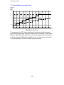
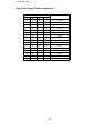
3.7.4 Drum Wear Correction Factor
Exposure
Lamp
Data
+10
(Max)
SP #61 = 0
+5
SP #61 = 1
+0
0
10
20
30
40
50
60
70
80
90
100
110 (Hours)
Main Motor On Time
To compensate for OPC drum wear caused by contact with the cleaning
brush, the exposure lamp voltage is increased at set intervals of main motor
ON time. When SP mode #61 is set to 0, exposure lamp data is increased 1
at 10-hour intervals. When SP mode #61 is set to 1, the data is increased 1
at 20-hour intervals. The total increase cannot exceed 8.
2-20
1 December 1990
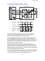
3.8 EXPOSURE LAMP CONTROL CIRCUIT
Main Board (PCB1)
B
AC Drive Board (PCB2)
TP111
Zero
Cross
R404
(EXPO)
E
CN108-1
CN122-7
ZD
401
CN421
240V
D401
R404
CN401-8
T402
ZD
402
CN419-1
DB401
Feed back signal
0V
CN122-6
CN401-7
CPU
+24V
ZD
403
VR401
C401
R403
220V
R406
220V Only
TR401
ThermoSW (TS)
Exposure
Lamp
(L1)
R411
R401
CN122-13
ZD
404
D
CN401-2
CN419-2
PC401
C
TRC401
24V
CR401
A
AC115V
AC220V
AC240V
C411
L401
L402
CN122-10
CN401-5
0V Trigger Pulse
R413
AC power
A
Zero cross
B
Trigger pulse
C
Lamp power
D
Feedback
signal
E
T407
Feedback
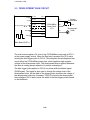
The main board sends lamp trigger pulses to the ac drive board from
CN122-10. PC401 activates TRC401, which provides ac power to the
exposure lamp, at the trailing edge of each trigger pulse.
The voltage applied to the exposure lamp is also provided to the feedback
circuit. The feedback circuit steps down (TR401), rectifies (DB401), and
smoothes (zener diodes and capacitors) the lamp voltage. The CPU monitors
the lowest point of the smoothed wave (feedback signal), which is directly
proportional to the actual lamp voltage.
The CPU changes the timing of the trigger pulses in response to the
feedback voltage. If the lamp voltage is too low, the CPU sends the trigger
pulses earlier so that more ac power is applied to the exposure lamp. This
feedback control is performed instantly; so, the lamp voltage is always stable
even under fluctuating ac power conditions.
The voltage applied to the exposure lamp can be changed with SP mode #48
(Light Intensity Adjustment). The ADS voltage adjustment (SP mode #56)
must be done whenever the light intensity adjustment is done.
2-21
1 December 1990
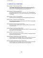
3.9 SERVICE CALL CONDITIONS
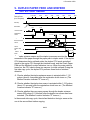
Service Code 11: Exposure Lamp Error
The feedback signal becomes higher than 4.2 volts (r.m.s.) for 1.0
second when the exposure lamp is on, or it becomes higher than 1.0
volt (r.m.s) for 1.0 second when the exposure lamp is off.
Service Code 12: Exposure Lamp Error
The feedback signal falls below 0.5 volt (r.m.s.) for 1.0 second when
the exposure lamp is on, or the exposure lamp stays on for longer than
10 seconds.
Service Code 13: Zero Cross Signal Error
The CPU does not receive the zero cross signal within 0.56 second.
Service Code 21: Scanner Home Position Error
The scanner home position sensor remains off (LOW) 8 seconds after
the main switch is turned on.
Service Code 22: Scanner Home Position Error
The scanner home position sensor is still on (HIGH) 1.0 second after
the scanner starts.
Service Code 28: Lens Home Position Error
The lens home position sensor remains off (LOW) 3.5 seconds after the
lens moves to the home position.
Service Code 29: Lens Home Position Error
The lens home position sensor is still on (HIGH) 3.5 seconds after the
lens leaves the home position.
Service Code 2A: 4th/5th Mirror Home Position Error
The 4th/5th mirror home position sensor is still on (HIGH) 2.5 seconds
after the 4th/5th mirror assembly moves to the home position.
Service Code 2B: 4th/5th Mirror Home Position Error
The 4th/5th mirror home position sensor is still off (LOW) 2.5 seconds
after the 4th/5th mirror assembly leaves the home position.
2-22
1 December 1990
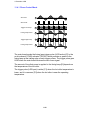
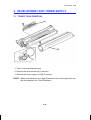
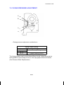
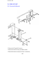
4. ERASE
4.1 OVERVIEW
LE
EL
SE
ES
Lo
Lc
LE: Lead edge erase margin
SE: Side erase margin
2.5 ±1.5 mm
2.0 ±2.0 mm on each side;
total of both sides 4 mm or less
LO: Original width
LC: Charged width of drum
EL: Lead edge erase
ES: Side erase
The erase lamp [A] consists of a line of LEDs extending across the full width
of the drum [B].
The erase lamp has three functions: leading edge erase, side erase, and trail
edge erase. Trail edge erase begins after the trailing edge of the copy paper;
therefore, the trailing edge of the copy will not be erased.
2-23
1 December 1990
a
b c
d
e
f
g
h
f
e
d
c b a
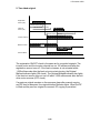
4.1.1 Lead Edge Erase
The entire line of LEDs turns on when the main motor turns on. They stay on
until the erase margin slightly overlaps the lead edge of the original image
area on the drum (Lead Edge Erase Margin). This prevents the toner density
sensor pattern from being developed every copy cycle and the shadow of the
original edge from being developed on the paper. At this point, side erase
starts. The width of the lead edge erase margin can be adjusted using SP
mode #41.
During the image density detection cycle (once every ten copy cycles), a
block of erase lamps (labeled "h" above) turns off long enough for the sensor
pattern to be developed.
The entire line of LEDs turns on when the residual voltage on the OPC drum
is being detected (Vr correction).
4.1.2 Side Erase
Based on the combination of copy paper size and the reproduction ratio data,
the LEDs turn on in blocks (labeled "a" – "h" above). This reduces toner
consumption and drum cleaning load.
2-24
1 December 1990
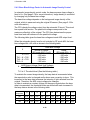
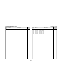
The following table shows which erase lamp LEDs turn on.
Blocks On
None
a
a–b
a–c
a–d
a–e
a–f
a – f, g
All
Paper Size
A3, A4 sideways
11" x 17", 11" x 8 1/2
B4
8 1/2" x 11", 8 1/2" x 5 1/2"
A4 lengthwise
B5 lengthwise
A5 lengthwise, 5 1/2" x 8 1/2"
Reproduction Ratio (%)
98 – 200
92 – 97
86 – 91
80 – 91
71 – 79
61 – 70
50 – 60
For ID sensor pattern
For Vr correction
4.1.3 Trailing Edge Erase
The entire line of LEDs turns on again to erase the trailing edge after the
latent image has passed. This prevents the trailing edge from appearing on
the copy. The LEDs stay on to erase the leading edge of the latent image in
the next copy cycle. After the final copy, the erase lamps turn off at the same
time as the main motor.
2-25
1 December 1990
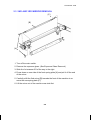
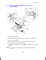
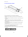
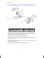
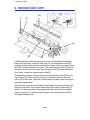
5. DEVELOPMENT
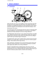
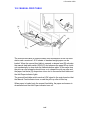
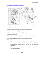
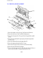
5.1 OVERVIEW
[B]
[E]
[C]
[F]
[A]
[D]
When the main motor turns on, the paddle roller [A] development roller [B]
the auger [C], and the agitator [D] start turning. The paddle roller picks up
developer in its paddles and transports it to the development roller. Internal
permanent magnets in the development roller attract the developer to the
development roller sleeve.
The turning sleeve of the development roller then carries the developer past
the doctor blade [E]. The doctor blade trims the developer to the desired
thickness and creates backspill to the cross-mixing mechanism.
The development roller continues to turn, carrying the developer to the OPC
drum. When the developer brush contacts the drum surface, the negatively
charged areas of the drum surface attract and hold the positively charged
toner. In this way, the latent image is developed.
The development roller is given a negative bias to prevent toner from being
attracted to non-image areas on the drum that may have residual negative
charge. The bias also controls image density.
After turning about 100 degrees more, the development roller releases the
developer to the developer tank. The developer is agitated by the paddle
roller, agitator [D], and the cross-mixing mechanism.
Rotation of the paddle roller and development roller tend to cause air
pressure inside the unit to become higher than the air pressure around the
development unit. A hole, fitted with a filter [F], has been added to the top of
the unit to relieve air pressure and to minimize toner scattering.
2-26
1 December 1990
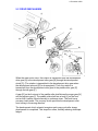
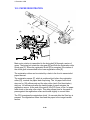
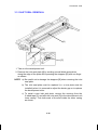
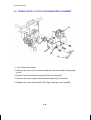
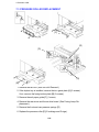
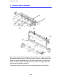
5.2 DRIVE MECHANISM
[I]
[G]
[E]
[H]
[J]
[B]
[F]
[A]
[D]
[C]
When the main motor turns, the rotation is transmitted from the development
drive gear [A] to the development roller gear [B] through the development
clutch [C]. (The rotation is transmitted to the development drive gear when
the development solenoid [D] is de-energized.) Then, the rotation is
transmitted from the development roller gear to the paddle roller gear [E]
through the idle gear [F].
A gear [G] on the front end of the paddle roller shaft drives the auger gear [H]
and the agitator gear [I]. The paddle roller shaft has a knob [J] on the front
end so that it can be turned manually to exchange toner. The knob has a
one-way clutch inside. The one-way clutch prevents the development roller
from turning in the wrong direction.
The development clutch solenoid energizes each copy cycle after image
development is completed. This stops the rollers, thereby reducing developer
fatigue.
2-27
1 December 1990
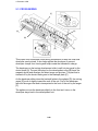
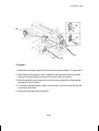
5.3 CROSS-MIXING
[F]
[D]
[A]
[B]
[E]
[C]
This copier uses a standard cross-mixing mechanism to keep the toner and
developer evenly mixed. It also helps agitate the developer to prevent
developer clumps from forming and helps create the triboelectric charge.
The developer on the turning development roller is split into two parts by the
doctor blade [A]. The part that stays on the development roller [B] forms the
magnetic brush and develops the latent image on the drum. The part that is
trimmed off by the doctor blade goes to the backspill plate [C].
As the developer slides down the backspill plate to the agitator [D], the mixing
vanes [E] move it slightly toward the rear of the unit. Part of the developer
falls into the auger inlet and is transported to the front of the unit by the auger
[F].
The agitator moves the developer slightly to the front as it turns, so the
developer stays level in the development unit.
2-28
1 December 1990
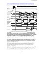
5.4 DEVELOPMENT BIAS FOR IMAGE DENSITY CONTROL
Image density is controlled by changing two items: (1) the strength of the bias
voltage applied to the development roller sleeve, and (2) the strength of the
voltage applied to the exposure lamp.
Applying a bias voltage to the development sleeve reduces the potential
between the development roller and the drum, thereby reducing the amount
of toner transferred. As the bias voltage becomes greater, the copy image
becomes lighter. Similarly, increasing the voltage to the exposure lamp
causes an increase in light intensity which also results in lighter copies.
The method of control is different depending on whether the image density is
manually selected or the automatic ID mode is used.
The development bias applied to the development roller sleeve has the
following three factors:
Development bias voltage = Base bias voltage factor
(Manual or automatic image density control)
+
Base bias voltage adjustment factor
+
Vr correction factor
The base bias voltage for non-image areas is –200 volts (Fixed).
5.4.1 Base Bias Voltage Factor In Manual Image Density Control
Darker
Manual ID Level
1
Base Bias Voltage
–120
Exposure Lamp Data Vo –4
Lighter
2
–120
Vo
3
–160
Vo
4
–200
Vo
5
6
–200 –240
Vo +4 Vo+8
7
–280
Vo+12
In manual ID control mode, the base bias voltage depends on the manually
selected ID level. The voltage applied at each ID level is shown in the above
table. The base exposure lamp voltage also varies depending on the manual
ID level as shown in the table. (See page 2-18 for more information.)
2-29
1 December 1990
5.4.2 Base Bias Voltage Factor In Automatic Image Density Control
In automatic image density control mode, the base exposure lamp voltage is
fixed to Vo. (See page 2-18 for more information.) Image density is controlled
by changing only the base bias voltage.
The base bias voltage depends on the background image density of the
original, which is measured using the original ID sensor. (See page 2-18 for
more information.)
The CPU checks the voltage output from the automatic ID circuit. This circuit
has a peak hold function. The peak hold voltage corresponds to the
maximum reflectivity of the original. The CPU then determines the proper
base bias level with reference to the peak hold voltage.
The following table gives the base bias voltages at each ADS output level.
When the automatic density level is set to darker by SP mode #34, the base
bias voltage shifts +40 volts as shown in the following table.
Base Bias Voltage
Normal or Lighter
Darker
(SP mode #34 = 0 or 2)
(SP mode #34 = 1)
K
K ≥ TH1
TH1 > K ≥ TH2
TH2 > K ≥ TH3
TH3 > K
K=
–200 volts
–260 volts
–320 volts
–380 volts
–160 volts
–220 volts
–280 volts
–340 volts
ADS Output Voltage (Peak Hold Voltage)
ADS Adjusted Voltage (SP #56)
TH1 to 3: Threshold level (See the following table.)
To maintain the correct image density, the lamp data is incremented when
the reproduction ratio is changed and/or drum wear correction is done. This
increment in the lamp data increases the intensity of light reflected from the
original. Therefore, the ADS output voltage also changes.
In order to maintain a constant voltage for the same original when the lamp
data is incremented, the threshold levels are shifted with each increment in
the lamp data as shown in the following table.
Increase of
lamp data
+0
+1
+2
+3
+4
+5
+6
+7
+8
+9
TH1
0.70
0.75
0.80
0.85
0.89
0.94
0.98
1.03
1.08
1.12
TH2
0.66
0.70
0.74
0.78
0.83
0.87
0.91
0.96
1.00
1.04
TH3
0.29
0.31
0.33
0.35
0.37
0.39
0.41
0.43
0.45
0.48
2-30
1 December 1990
5.4.3 Base Bias Voltage Adjustment Factor
Base Bias Adjustment
(Black toner: SP mode #37, Color Toner: SP mode #79)
Image Density
Normal
Darkest
Darker
Lighter
Lightest
SP Data
(SP mode #37 or #79)
0
1
2
3
4
Change of
Base Bias Voltage
±0 volts
+40 volts
+20 volts
–20 volts
–40 volts
The base bias voltage can be changed in SP mode #37 for black toner or
#79 for color toner to adjust the image density level. The above table gives
the base bias voltage for each SP mode setting. This adjustment should be
done only when the exposure lamp voltage adjustment (SP mode #48) fails
to achieve the desired image density.
5.4.4 Vr Correction Factor
As the OPC drum is used, drum residual voltage (Vr) gradually increases. Vr
correction compensates for residual voltage on the drum. Vr correction is
done every 1,000 copies based on the data of the drum counter (SP mode
#69) and the Vr correction ratio (L) (SP mode #67). The following chart
shows how the bias voltage changes depending on the Vr correction ratio (L).
Vr Correction Factor
L
100 to 89 (%)
88 to 76 (%)
75 to 62 (%)
61 to 45 (%)
44 to 0 (%)
Change of Bias Voltage
±0 (volts)
–40 (volts)
–80 (volts)
–120 (volts)
–160 (volts)
NOTE: L = Vrp/Vsg x100 (Vr Correction Ratio)
Vrp: ID sensor output for Vr correction pattern
Vsg: ID sensor output for bare drum
When the Vr correction is made every 1,000 copies, all blocks of erase lamps
turn on and the development bias becomes 0 volts to develop the Vr
correction pattern.
2-31
1 December 1990
5.5 DEVELOPMENT BIAS CIRCUIT
CN112-8
CN1-1
CN112-7
CN1-2
CN112-6
CN1-3
CN112-5
CN1-4
CN112-4
CN1-5
CN112-3
CN1-6
VA [24]
VC [5]
Bias Trig (PWM) [
0
0/5]
Bias FB
GND [0]
CN112-2
CN1-7
CN112-1
CN1-8
CC/Grid/Bias
Power Pack
(P1)
TC
Charge
Corona Wire
TG
Grid
TB
Development
Roller
Main Board (PCB 1)
The main board supplies +24 volts to the CC/Grid/Bias power pack at CN1-1
as the power supply source. When the Start key is pressed, the CPU starts
sending the bias trigger pulse to CN1-4. This energizes the development bias
circuit within the CC/Grid/Bias power pack, which applies a high negative
voltage to the development roller. The development bias is applied whenever
the drum is rotating except when the Vr pattern is developed.
The bias trigger pulse applied to CN1-4 is a pulse width modulated signal
(PWM signal). This signal is also used to change the voltage level of the
development roller. As the width of the trigger pulses increase, the voltage of
the development roller also increases. The CPU monitors the development
bias voltage at CN1-6 and controls the width of the bias trigger pulses based
on this feedback.
2-32
1 December 1990
5.6 DEVELOPMENT UNIT SET SENSOR
[B]
[A]
When the development unit is removed from the copier, the development unit
set sensor (S12) [A] sends a LOW signal to the main board and "U3" lights in
the operation panel. When the development unit is properly set in the copier,
the sensor is actuated by a projection [B] on the rear of the toner supply unit
and "U3" turns off.
2-33
1 December 1990
5.7 COLOR DEVELOPMENT UNIT DETECTION
[A]
[D]
[A]
[B]
[C]
[C]
[D]
Color Development Unit Detection Table
SW 8-1
OFF
ON
OFF
ON
SW 8-2
OFF
OFF
ON
ON
Color
Black
Red
Green
Blue
ON: LOW
OFF: PULSE
When a color development unit is installed in the copier, the color switch [A]
is activated by screw [B] at the rear side of the development unit. The color
switch has two microswitches (SW8-1 [C] and 8-2 [D]) inside. The CPU
receives a LOW signal from the microswitch activated by the screw and
determines which color unit has been installed.
2-34
1 December 1990
6. TONER DENSITY DETECTION AND TONER
SUPPLY
6.1 DETECT SUPPLY MODE
Sensor
Pattern
Original Lead Edge
Original
ON
OFF
A
B
ON
C
OFF
D
E
Leading Edge Erase
Development
Bias
ID Sensor
Pattern
RAM Clear
1
2
3
4
5
6
7
8
Toner Density Detection
9
10
11
12
13
14
20
21
Toner Density Detection
Toner Density
Detection
2nd
1st
22
3rd
Low Toner Density
Toner Supply Timing
Detection
Toner Add
Toner Supply Clutch ON
(10 times)
Detection
The CPU checks toner density by directly sensing the image density every 10
copy cycles (every 5 copies for the color development unit). If the RAM is
cleared (SP mode #99), or a new RAM is installed, the CPU checks the
image density at the beginning of the first copy cycle.
During the check cycles, the sensor pattern is exposed prior to exposure of
the original. After the sensor pattern is developed, its reflectivity is checked
by the image density sensor (a photosensor). The CPU notes the reflectivity.
If the reflected light is too strong, indicating a too low toner density condition,
toner is added to the development unit.
The toner is not added all at once. The CPU energizes the toner supply
clutch solenoid for the proper amount of time to add a selected amount of
toner over the next 10 cycles.
When a color development unit is used, the CPU automatically selects fixed
toner supply mode.
2-35
1 December 1990
6.2 ID SENSOR FUNCTION IN DETECT SUPPLY MODE
Main Board
I/D Sensor
+5V
B
A
C
K
E
+24V
CN118-2
CN110-2
TP 110
(PSE)
SOL 1
CN110-3
C
ID Sensor Output
R
IC111
ROM
VR102
A
CN110-1
ID Sensor LED
CPU
IC 105
I/O
IC190
RAM
CN118-1
Toner Supply
CL Solenoid
Vsg 4V
Low Density
(1/8 Vsg)
High Density
Vsp
[BLACK]
The image density sensor checks the density of the sensor pattern image
once every 10 copy cycles. The CPU receives two voltage values directly
from the sensor: the value for the bare drum (Vsg) and the value for the
sensor pattern (Vsp). These two values are then compared to determine
whether more toner should be added.
1. Vsp ≤1/8 Vsg .....No toner is added. (High density)
2. Vsp >1/8 Vsg .....Toner is added.(Low density)
When the image density is too low, the CPU activates the toner supply clutch
solenoid to add toner over the next 10 copy cycles. The amount of toner
added depends on the value of Vsp, the selected toner supply ratio (SP
mode #31) and the paper size in use. (See page 2-42 for more information.)
When the data of SP mode #35 is set to "1" (factory setting = "0"), the CPU
changes the interval of the ID check from every 10 copies to every 5 copies
for the black development unit.
2-36
1 December 1990
6.3 FIXED SUPPLY MODE
When the data of SP mode #30 is "1" (factory setting = "0") or a color
development unit is installed, the fixed supply mode is selected. In this case,
a fixed amount of toner is added every copy cycle depending on the selected
toner supply ratio (SP mode #32 (black toner), SP mode #70 (color toner),
the paper size in use, and the supply mode data. (See page 2-44 for more
information.)
2-37
1 December 1990
6.4 ID SENSOR FUNCTION IN FIXED SUPPLY MODE
6.4.1 Black Development Unit
In fixed supply mode, toner is supplied every copy cycle according to the
fixed toner supply ratio data (SP mode), the paper size data and the color
data. However, the toner supply clutch solenoid is de-energized to prevent
over-toning when Vsp is lower than 1/8 Vsg.
Vsg 4V
Low Density
1/8 Vsg
Vsp
High Density
[BLACK]
6.4.2 Color Development Unit
When a color development unit is installed, the CPU automatically selects the
fixed toner supply mode. The amount of toner supplied depends on the fixed
toner supply ratio (SP mode #70), the paper size data and the kind of color
data.
The CPU calculates the threshold level for toner supply when the color
developer initial setting (SP mode #10) procedure is completed. This level is
determined by calculating the average of Vsp/Vsg x 100 (%).
Since the fixed supply mode is selected when in color toner mode, it is
necessary to inhibit toner supply if the toner density becomes high to prevent
over-toning. The CPU checks Vsp once every 5 copy cycles. If Vsp becomes
lower than the threshold level, the CPU stops supplying toner. Toner supply
resumes when Vsp rises above the threshold level again.
Vsg 4V
Low Density
Threshold Level
Vsp
High Density
[COLOR]
The threshold level (a percentage) for each color can be monitored in SP
mode #80 (Red), #81 (Green) and #82 (Blue).
2-38
1 December 1990
6.5 ABNORMAL CONDITION IN TONER DENSITY
DETECTION
If the Vsg goes below 2.5 volts (Vsg abnormal) or Vsp goes above 2.5 volts
(Vsp abnormal) 5 times in a row, the CPU determines that toner density
detection is abnormal. The CPU changes from the detect supply mode to the
fixed supply mode. At the same time either the Auto ID indicator or the
selected manual ID level starts blinking, and the machine can be operated.
Abnormal Condition In Toner Density Detection
SP mode #55 Display
Vsp
Vsg
Conditions
varies
0.00
Vsg ≤ 2.5 (Vsg Abnormal)
varies
5.00
Vsp ≥ 2.5 (Vsp Abnormal)
6.6 DEVELOPMENT BIAS FOR ID SENSOR
The development bias for the ID sensor consists of the following 2 factors:
Development bias voltage = Toner density adjustment factor
+
Vd correction factor
The development voltage for the Vr correction is 0 volts.
6.6.1 Toner Density Adjustment Factor
Toner Density Adjustment
(Black Toner: SP Mode #33, Color Toner: SP Mode #75)
Toner Density
SP Data
(SP mode
#33 or #75)
Normal
0
Low
1
High
2
Higher
3
Developer Initial Setting
Development Bias Voltage
Black Toner
Red Toner
Blue Toner
Green Toner
–260 volts
–220 volts
–280 volts
–300 volts
–340 volts
–240 volts
–200 volts
–260 volts
–280 volts
–280 volts
–300 volts
–260 volts
–320 volts
–340 volts
–240 volts
–320 volts
–280 volts
–340 volts
–360 volts
–240 volts
The development bias can be adjusted by SP mode #33 for black toner or
#75 for color toner to adjust the toner density level. The above chart shows
the development bias voltage corresponding to setting of SP #33 or #75. This
adjustment should be used only when the exposure lamp voltage adjustment
(SP mode #48) can not achieve the desired image density.
2-39
1 December 1990
6.6.2 Vd Correction Factor (Only For Black Toner)
After developer is replaced, the triboelectric charge sometimes changes as
the new developer mixture is not stabilized in during the first 500 copies. The
development bias for the ID sensor is adjusted automatically to compensate
for these changes.
The CPU calculates the threshold level for the Vd correction when the black
developer initial setting procedure (SP mode #65) is completed. This
threshold level is the average of Vsp/Vsg x 100 (%). The result of the
calculation can be monitored by SP mode #64. The CPU has a software
counter to count number of copies made with the developer. The counter
resets to "0" when SP mode #65 is performed. The Vd correction is made
based on the data of the counter and of SP mode #64. The following table
gives the threshold levels for each data value of SP#64.
SP Data
(SP mode #64)
Vsp/Vsg x100 (%)
0
1
2
3
4
12 to 15
0 to 7
8 to 11
16 to 21
More than 22
Change of Development Bias Voltage
0 to 499 copies
More than 500 copies
±0 volts
–40 volts
–20 volts
±0 volts
±0 volts
2-40
±0 volts
±0 volts
±0 volts
+20 volts
+40 volts
1 December 1990
6.7 TONER SUPPLY AND AGITATOR DRIVE MECHANISM
[H]
[F]
[J]
[I]
[E]
[F]
[G]
[B]
[A]
[C]
[D]
The toner supply clutch gear [A] turns when the main motor is on. The
transmission of this rotation to the toner supply drive gear [B] is controlled by
the toner supply clutch [C].
When the toner supply clutch solenoid [D] energizes, the toner supply clutch
engages and starts turning the toner supply drive gear. The toner supply
drive gear turns the toner supply roller gear [E]. Toner catches in the grooves
on the toner supply roller [F]. Then, as the grooves turn past the pin hole
plate [G], the toner drops into the development unit through the pin holes.
The toner agitator [H] mechanism, which is contained in the toner cartridge,
prevents toner from blocking. The toner agitator gear [I] turns whenever the
toner supply clutch solenoid is engaged. Rotation passes through the toner
cartridge casing to the agitator junction [J].
2-41
1 December 1990
6.8 TONER SUPPLY AMOUNT
This copier has two different ways of controlling the amount of toner supplied.
Normally, the detect supply mode controls toner supply for the black
development unit; however, a fixed supply mode also can be selected by SP
mode #30. When the color development unit is installed, the fixed supply
mode controls toner supply regardless of the setting of SP mode #30.
6.8.1 Detect Supply Mode (SP mode #30 = 0)
The amount of toner supplied depends on the ID sensor data, the detect
toner supply ratio data, and the paper size. The toner supply clutch solenoid
on time in each copy cycle is calculated as follows:
Toner Supply Clutch Solenoid ON Time = I x T x P (pulses)
Where : I = ID Sensor Data
T = Detect Toner Supply Ratio Data
P = Paper Size Data
For example: Vsp = 0.65 volts, which means the toner
supply level is "2" and the ID sensor = 29.
The data of SP mode #31 is set to "0".
The toner supply ratio is 15 % and the toner
supply data = 2.
Paper size is A4 or LT.
The paper size data = 1.
Toner Supply Clutch ON Time = I x T x P
= 29 x 2 x 1
= 58 (pulses)
= 232 (m sec.) (1 pulse = 4.0 m sec.)
2-42
1 December 1990
ID Sensor Data
Vsp/Vsg x100
(Vsp, if Vsg = 4.0 volts)
(Toner Supply Ratio, if SP #31 = 0)
Toner Supply Level
0 to 12.5 %
(0 to 0.5 volts)
No toner supply
(0 %)
0
12.5 to 15.0 %
(0.5 to 0.6 volts)
1
(3.75 %)
15
15.0 to 17.5 %
(0.6 to 0.7 volts)
2
(7.5 %)
29
17.5 to 25.0 %
(0.7 to 1.0 volts)
3
(15 %)
59
25.0 to 62.5 %
(1.0 to 2.5 volts)
(See note below.)
4
(30 %)
118
62.5 to more than 100 %
(2.5 to 5.0 volts)
Fixed supply mode
N/A
ID Sensor Data
NOTE: If this condition is detected two times consecutively, the toner supply
ratio rises to 60% (ID Sensor Data = 236), which is double that at
toner supply level 4.
Detect Toner Supply Ratio Data (SP mode #31)
SP Data
(SP mode #31)
0
1
2
3
Toner Supply Ratio
Toner Supply Ratio Data
15 %
7%
30 %
60 %
2
1
4
8
Paper Size Data
Paper Size
Paper Size ≤ A4 or LT
Paper Size > A4 or LT
Paper Size Data
1
2
2-43
1 December 1990
6.8.2 Fixed Supply Mode (SP mode #30 = 1)
The amount of toner supplied depends on the fixed toner supply ratio data,
the paper size data and the color data. The toner supply clutch solenoid on
time in each copy cycle is calculated as follows:
Toner Supply Clutch Solenoid ON Time = T x P x 2 x C (pulses)
Where: T = Fixed Toner Supply Ratio Data
P = Paper Size Data
C = Color Data
For example: The data of SP mode #32 is set to "0".
The toner supply ratio is 7.0% and the toner
supply data = 2.
Paper size is A4. The paper size data = 29.
Black toner is used. The color data = 1.
Toner Supply Clutch ON Time = T x P x 2 x C
= 2 x 29 x 2 x 1
=116 (pulses)
= 464 (m sec.) (1 pulse = 4.0 m sec.)
2-44
1 December 1990
Fixed Toner Supply Ratio Data (Black Toner: SP mode #32)
SP Data
(SP mode #32)
0
1
2
3
Toner Supply Ratio
Toner Supply Ratio Data
7.0 %
3.5 %
10.5 %
14.0 %
2
1
3
4
Fixed Toner Supply Ratio Data (Color Toner : SP mode #70)
SP Data
(SP mode #70)
0
1
2
3
Toner Supply Ratio
Toner Supply Ratio Data
14.0 %
7 .0%
21.0 %
28.0 %
2
1
3
4
Paper Size Data
Paper Size
A3
B4
A4
B5
A5
B6
11" X 17"
8 1/2" X 14"
8 1/2" X 11"
5 1/2" X 8 1/2"
Paper Size Data
58
43
29
23
15
11
55
37
27
14
Universal (*)
Paper size not detected
29
0
Color Data
Color
Black
Red
Blue or Green
Color Data
1
2
1.2
2-45
1 December 1990
6.9 TONER END DETECTION
[E]
[C] [D]
[G]
[F]
[B]
[A]
The toner agitator gear [A] has a cam [B] (the toner end cam) on its inner
surface, and it rotates only when toner is supplied. The cam follower on the
end of the toner end lever [C] rides on the surface of the toner end cam
(spring pressure). The opposite end of the toner end lever alternately presses
and releases the toner end arm [D] as the cam turns. The toner end plate [E],
which is in the toner hopper, is mounted on the same shaft as the toner end
arm.
When there is sufficient toner in the hopper, the toner end plate is prevented
from moving by the toner. Therefore, even when the toner end lever drops to
the lowest position on the cam (releasing the toner end arm), the toner end
arm does not move and the toner end sensor [F] is not activated.
When there is insufficient toner in the hopper, the toner end plate can move.
When the toner end lever releases the toner end arm, the toner end plate
lowers and the actuator [G] on the toner end arm moves into the toner end
sensor. The CPU receives a single pulse from the toner end sensor.
2-46
1 December 1990
If this condition is detected by the CPU two times consecutively, the Add
Toner indicator starts blinking.
After the indicator starts blinking, 50 copies can be made. If a new toner
cartridge is not added within that 50 copy interval, the Add Toner indicator
stops blinking (stays on) and copying is inhibited. If the main switch is turned
off and on after this, only 1 copy can be made each time.
The toner end condition is normally detected by the mechanism described
here. However, it can also be detected using the ID sensor. The Add Toner
indicator will start blinking in the following cases:
Black Development Unit:
If Vsp exceeds 1/4 Vsg 10 times in a row.
Color Development Unit:
If Vsp/Vsg exceeds 1.1 x threshold level 10
times in a row. The threshold level is the
average of Vsp x Vsg, which is calculated and
stored in RAM when the color developer initial
setting (SP mode #10) procedure is
completed.
When Vsp exceeds 1/4 Vsg in the black development unit, the CPU checks
toner density every 5 copy cycles instead of every 10 copy cycles.
When the toner cartridge is replaced and the front cover is closed, the CPU
turns on the main motor, the development clutch solenoid, and the toner
supply clutch solenoid for approximately 3 seconds to supply toner to the
empty toner supply unit from the toner cartridge. A toner end check is also
done during this 3 second period. The CPU performs this operation a
maximum of 3 times (9 seconds) to clear the toner end condition.
6.10 TONER SUPPLY UNIT INITIAL SETTING (SP mode #63)
When a brand-new machine is installed or the toner supply unit is replaced
with a new one, the toner supply unit initial setting (SP mode #63) must be
performed to prevent the CPU from falsely detecting toner end.
When SP mode #63 is performed, the CPU turns on the main motor, the
development clutch solenoid, and the toner supply clutch solenoid for
approximately 3 seconds to supply toner to the empty toner supply unit from
the toner cartridge. A toner end check is also done during this 3 second
period. The CPU performs this operation a maximum of 3 times (9 seconds)
to clear the toner end condition.
2-47
1 December 1990
7. IMAGE TRANSFER AND PAPER
SEPARATION
[B]
[F]
[E]
[D]
[C]
[A]
7.1 PRE-TRANSFER LAMP (PTL)
After the latent image is developed but before the image is transferred to the
copy paper, the drum surface is illuminated by the pre-transfer lamp [A]. This
illumination reduces the negative potential on the drum surface [B]. This
prevents the toner particles from being re-attracted to the negatively charged
drum during the paper separation process. It also makes image transfer and
paper separation easier.
7.2 IMAGE TRANSFER
A high negative voltage (–4.8 kilovolts) is applied to the transfer corona wire
[C], and the corona wire generates negative ions. These negative ions are
applied to the copy paper, and the negative charge attracts the positively
charged toner away from the drum and onto the paper. In addition, the paper
is held against the drum by the positive counter charge on the drum.
2-48
1 December 1990
7.3 PAPER SEPARATION
After image transfer the copy must be separated from the drum. To break the
attraction between the paper and the drum, the separation corona wire [D]
applies an ac corona to the reverse side of the paper. The stiffness and
weight of the paper causes it to separate from the drum.
The negative charge on the paper (from the transfer corona) is not
completely discharged until the paper is far enough from the drum that the
toner will not be reattracted to the drum. The two pick-off pawls [E] ensure
that thin, low stiffness paper and upward curled paper separate completely.
The spurs [F] prevents the unfused toner on the paper from being smeared
by the pick-off pawls.
2-49
1 December 1990
7.4 PRE-TRANSFER LAMP AND TRANSFER/SEPARATION
CORONA CIRCUIT
CN121-2
[24] VA
VA [24]
TC2 Trig [ 24]
TC1 Trig [ 24]
SC Trig [ 24]
GND [0]
CN126-5
CN1-1
CN126-4
CN1-2
CN126-3
CN1-3
CN126-2
CN1-4
CN126-1
CN1-5
TC/SC
Power Pack
(P2)
Transfer Corona
Separation Corona
CN121-1
PTL (L5)
[ 24] PTL
Main Board
(PCB1)
When the Start key is pressed, the main board outputs Low signals to turn on
the pre-transfer lamp (PTL) and the TC/SC power pack for the transfer and
separation coronas.
The pre-transfer lamp is composed of 50 LEDs supplied by +24 volts.
The TC/SC power pack has a dc to dc converter and a dc to ac inverter. The
dc to dc converter changes +24 volts to -4.8 kilovolts for the transfer corona.
The inverter changes +24 volts to the 5.0 kilovolts ac (500 Hz) for the
separation corona.
The TC2 trigger is only used for the second side copies in duplex copy mode.
This shifts the corona current to increase transfer efficiency.
The separation corona circuit in the TC/SC power pack has a current leak
detection circuit for safety. When this circuit detects that more than 2
milliampere is supplied to the separation corona, the separation corona turns
off immediately. When the main switch is turned off and on, or the front cover
or the exit cover is opened and closed, this condition is cleared.
2-50
1 December 1990
8. DRUM CLEANING
8.1 OVERVIEW
[E]
[B]
[C]
[D]
[A]
[F]
The cleaning brush [A] and cleaning blade [B] remove any toner remaining
on the drum [C] after the image is transferred to the paper.
The cleaning brush and drum move in opposite directions at their point of
contact. The cleaning brush removes paper dust and nearly half of the toner
from the drum surface to reduce the cleaning load placed on the blade.
The cleaning blade removes the remaining toner. The falling toner catches in
the fibers of the cleaning brush and is carried inside the cleaning unit. The
toner collection roller [D] carries the used toner to the used toner tank. The
light of the quenching lamp [E] neutralizes any charge remaining on the drum
in preparation for the next copy cycle.
The cleaning blade releases when the release knob is pressed. This cleans
the edge of the cleaning blade using the blade scraper [F], which is mounted
under the cleaning blade.
2-51
1 December 1990
8.2 DRIVE MECHANISM
[G]
[H]
[D]
[C]
[F]
[E]
[B]
[A]
The rotation of the main motor is transmitted to the cleaning unit through the
main motor gear [A], the relay gear [B], and the cleaning drive gear [C].
The gear [D] driven by the cleaning drive gear passes the rotation to the
toner collection roller gear [E] and to the cleaning brush gear [F] through the
idle gears [G].
The cleaning blade [H] is mounted in the center of the blade and is tilted to
apply even pressure.
2-52
1 December 1990
8.3 TONER OVERFLOW DETECTION
[C]
[B]
[A]
The toner overflow detection mechanism stops copier operation when the
used toner tank gets full. When the tank gets full, the pressure of the used
toner pushes up a movable plate [A] mounted in the top of the used toner
tank. As this plate moves up, it raises the toner overflow actuator [B]. When
the actuator moves into the toner overflow sensor [C], the CPU starts to blink
"E70" on the operation panel. After the "E70" starts to blink, 250 copies can
be made. Then, after 250 copies the "E70" stops blinking (stays on) and
copying is inhibited.
2-53
1 December 1990
9. QUENCHING
[A]
[B]
In preparation for the next copy cycle, light from the quenching lamp (QL) [A]
neutralizes any charge remaining on the drum [B].
The neon lamp is used for quenching and it is turned on whenever the main
motor rotates.
2-54
1 December 1990
10. PAPER FEED AND REGISTRATION
10.1 OVERVIEW
[G]
[C]
[D]
[A]
[B]
[E]
[H]
[I]
[J]
[F]
This model has two paper feed stations. The first feed station is located on
the right side of the copier and the second feed station is located inside the
copier. The first feed station uses a cassette [A] which can load 500 sheets,
and the second feed station uses a drawer type tray [B] which can load 250
sheets. Paper can also be fed using the manual feed table [C], which utilizes
the feed mechanism of the first feed station.
The first feed station uses a FRR feed system. Rotation of the pick-up roller
[D] drives the top sheet of paper from the cassette to the feed and the
reverse rollers. The feed [E] and reverse [F] rollers then take over the paper
drive. If more than one sheet is fed by the pick-up roller, the reverse roller
rotates in the opposite direction and prevents all but the top sheet from
passing through to the registration rollers [G].
The second feed station uses the semicircular feed roller [H] and corner
separator [I] system. The semicircular feed roller makes one rotation to drive
the top sheet of paper to the relay rollers [J], which then feed the sheet to the
registration rollers. The corner separator allows only one sheet to feed.
2-55
1 December 1990
10.2 FRR FEED SYSTEM
[B]
[A]
[C]
This copier uses an FRR (Feed + Reverse Roller) paper feed system which
utilizes three rollers.
10.2.1 Pick-up Roller
The pick-up roller [A] is not in contact with the paper stack before it starts
feeding paper. Shortly after the Start key is pressed, the pick-up roller drops
down and feeds the top sheet between the feed [B] and the reverse rollers
[C]. At almost the same time that the paper’s leading edge arrives at the feed
roller, the pick-up roller lifts off the paper stack so that it does not interfere
with the operation of the feed and reverse rollers. The feed and reverse
rollers then take over the paper feed process.
10.2.2 Feed and Reverse Rollers
There is a one-way bearing inside the feed roller so it can turn only in one
direction. The reverse roller is driven in the opposite direction to the feed
roller. The reverse roller, however, is driven through a slip clutch (torque
limiter clutch) which allows it to turn in either direction depending on the
friction between the rollers. A spring keeps the reverse roller in contact with
the feed roller.
2-56
1 December 1990
[B]
[B]
F2
F2
F3
F2
F1
F1
F3
[A]
F1
F1
[A]
The direction that the reverse roller [A] turns depends on the frictional forces
acting on it. The slip clutch applies a constant clockwise force (F1). When
there is a single sheet of paper being driven between the rollers, the force of
friction between the feed roller [B] and the paper (F2) is greater then F1. So,
the reverse roller turns counterclockwise.
If two or more sheets are fed between the rollers, the forward force on the
second sheet (F3), becomes less than F1 because the coefficient of friction
between the two sheets is small. So, the reverse roller starts turning
clockwise and drives the second sheet back to the cassette.
2-57
1 December 1990
10.3 1ST FEED STATION PAPER LIFT MECHANISM AND
PAPER END DETECTION
[H]
[K]
[J]
[I]
[G]
[A]
[F]
[E]
[B]
[C]
[D]
10.3.1 Paper Lift Mechanism
When the cassette [A] is inserted into the copier, the cassette actuator pin [B]
is pushed down by the cassette. The paper lift clutch unit [C] moves down
and then the paper lift gear [D] engages with the sector gear [E].
Simultaneously, the paper size actuator [F] actuates the paper size switch [G].
Under the following conditions, the CPU checks the paper lift sensor [H] to
see if the paper is at the feed position:
1. When the Start key is pressed.
2. When the warm-up condition changes to the ready condition.
3. When the manual feed table is closed.
2-58
1 December 1990
If the paper has not been raised to the feed position, the CPU turns on the
main motor and the paper lift clutch. The paper lift gear turns the sector gear
and the bottom plate raises until the top sheet pushes up the paper lift sensor
feeler [I]. When the paper lift sensor is de-actuated, the paper lift sensor
sends a Low signal to the main board, and then the main motor and the
paper lift clutch are turned off.
If the tray lift sensor stays HIGH for 7 seconds after the paper lift clutch is
turned on, "U5" lights in the operation panel.
As paper is fed into the copier, the level of paper stack gets lower. If the level
becomes too low, the paper lift sensor is actuated and the CPU energizes the
paper lift clutch until the top sheet raises the feeler to de-actuate the paper lift
sensor again. This ensures that the paper is always at the correct feed height.
10.3.2 Paper End Detection
When the cassette runs out of paper, the paper end feeler [J] drops through a
slot in the cassette bottom plate. As it drops, the paper end sensor [K] is
actuated by the feeler. The paper end sensor then sends a HIGH signal to
the main board. The Add Paper indicator then turns on. The Wait indicator
keeps turning on and the machine stops after the copy cycle is finished.
2-59
1 December 1990
10.4 2ND FEED STATION PAPER LIFT MECHANISM AND
PAPER END DETECTION
[I]
[H]
[J]
[G]
[K]
[F]
[A]
[D]
[E]
[B]
[C]
10.4.1 Paper Lift Mechanism
When the paper tray [A] is closed after the paper is loaded, the release shaft
[B] is pushed by the rear frame [C] and releases the lock arm [D], which is
mounted on the paper tray bottom plate.
Once the lock arm is released, the bottom plate is raised by the pressure
spring [E] and the top sheet pushes up the corner separator [F] and stops at
the correct feed height.
10.4.2 Paper End Detection
When the paper tray runs out paper, the paper end feeler [G] drops through a
slot in the tray bottom plate. The paper end actuator [H], which is on the
same shaft as the paper end feeler, pivots into the paper end sensor [I]. The
paper end sensor sends a HIGH signal to the main board and then the Add
Paper indicator turns on. The Wait indicator keeps turning on and the
machine stops after the copy cycle is finished.
When the paper tray is pulled out, the release arm [J], which is spring loaded,
rotates clockwise and lifts the paper end actuator and the paper end feeler.
This prevents the paper end feeler from being damaged by the paper tray.
When the paper tray is closed, the projection [K] on the paper tray pushes the
release arm to release the paper end actuator and the paper end feeler.
2-60
1 December 1990
10.5 PAPER SIZE DETECTION
10.5.1 1st Feed Station
[A]
SW3–
12345
[B]
The paper size switch (SW3) [A] in the cassette entrance detects the paper
size. The paper size switch has five microswitches (SW3-1 through 3-5)
inside. The paper size switch is actuated by an actuator plate [B] on the rear
of the cassette. Each paper size has its own unique combination of notches
in the plate. The CPU receives a LOW signal from the microswitches
activated by the actuator and determines which cassette was inserted.
2-61
1 December 1990
Paper Size Detection Table (1st Feed Station)
Paper Size
Universal
A3
B4
A4
A4
B5
B5 (lengthwise)
A5 (sideways)
A5 (lengthwise)
B6 (sideways)
B6 (lengthwise)
Return Post Card
Post Card
11" x 17"
11" x 8 1/2"
11" x 15"
10" x 14"
8 1/2" x 14"
8 1/2" x 13"
8 1/2" x 11"
8 1/2" x 5 1/2"
8 1/4" x 13" (14")
F (8" x 13")
8" x 10 1/2"
8" x 10"
5 1/2" x 8 1/2"
No Cassette
1
0
1
1
0
1
0
1
0
1
0
1
0
1
0
1
0
1
0
1
0
1
0
1
0
1
0
1
Switch 3 –
2 3 4
0 0 0
0 0 0
1 0 0
0 1 0
0 1 0
1 1 0
1 1 0
0 0 1
0 0 1
1 0 1
1 0 1
0 1 1
0 1 1
0 0 0
0 0 0
1 0 0
1 0 0
0 1 0
0 1 0
1 1 0
1 1 0
0 0 1
0 0 1
1 0 1
1 0 1
0 1 1
1 1 1
5
0
0
0
0
0
0
0
0
0
0
0
0
0
1
1
1
1
1
1
1
1
1
1
1
1
1
1
Size Indication
*
A3
B4
A4
A4
*
*
A5
A5
*
*
*
*
11 x 17
8 1/2 x 11
*
*
8 1/2 x 14
*
8 1/2 x 11
5 1/2 x 8 1/2
*
F
*
*
5 1/2 x 8 1/2
0: Low (ON)
1: High (OFF)
2-62
1 December 1990
10.5.2 2nd Feed Station
[E]
[F]
[A]
[B]
[C]
[D]
Four paper size switches (SW4 [A], SW5 [B], SW6 [C], and SW7 [D]) on the
rear frame detect the paper size. The paper size switches are actuated by an
actuator plate [E] on the rear of the paper tray. The paper end guide [F] is
connected to the actuator plate. When the paper end guide is pushed against
the paper stack loaded in the cassette, the actuator plate slides into position
and actuates the appropriate paper size switch.
Paper Size Detection Table (2nd Feed Station)
Paper Size
A3
F (8" x 13")
A4 lengthwise
A4 sideways
B4
11" x 17"
11" x 8 1/2"
8 1/2" x 11"
8 1/2" x 14"
4
0
1
1
1
0
0
1
1
1
0
Switch
5 6
1 1
0 1
0 0
1 0
0 1
1 1
1 1
1 0
0 1
0 0
7
1
1
1
1
1
1
0
1
1
0
2-63
Size Indication
A3
F
A4
A4
B4
11" x 17"
8 1/2" x 11"
8 1/2" x 11"
8 1/2" x 14"
Duplex Unit
0: Low (ON)
1: High (OFF)
1 December 1990
10.6 PAPER FEED DRIVE MECHANISM
10.6.1 1st Feed Station
[H]
[F]
[A]
[E]
[G]
[B]
[C]
[D]
Through several gears and a timing belt, main motor rotation is transmitted to
the relay gear [A] and then the 1st paper feed clutch gear [B]. The 1st paper
feed clutch gear turns the reverse roller drive gear [C]. The paper feed timing
is controlled by the 1st paper feed clutch [D].
The pick-up roller [E] is normally in contact with the paper stack. When the
leading edge of the paper passes between the feed roller [F] and the reverse
roller [G], the pick-up roller is then lifted up by the pick-up roller release
solenoid [H]. After the trailing edge of the paper passes under the pick-up
roller, the pick-up roller release solenoid is de-energized and the pick-up
roller drops back onto the paper stack in preparation for the next copy cycle.
2-64
1 December 1990
10.6.2 2nd Feed Station
[H]
[D]
[E]
[C]
[A]
[F]
[B]
[G]
Main motor rotation is transmitted to the relay roller clutch gear [A] through
gears and a timing belt. The paper feed timing is controlled by the relay roller
clutch [B] and the 2nd feed clutch [C]. The relay roller gear [D] transmits
rotation to the 2nd feed clutch gear [E] through the relay gear [F] only when
the relay roller clutch is on (when the relay clutch solenoid [G] is energized).
Both the relay roller clutch and the 2nd paper feed clutch turn on at the same
time to start paper feed. The 2nd feed clutch is energized for 500
milliseconds to transfer drive to the 2nd feed roller shaft and turns the 2nd
feed rollers [H]. The 2nd feed rollers stop turning when the 2nd feed clutch
gear completes one rotation. The relay roller clutch solenoid stays energized
until the leading edge of the paper reaches the registration rollers.
2-65
1 December 1990
10.7 SLIP CLUTCH MECHANISM
[D]
[B]
[A]
[C]
[E]
[D]: Reverse Roller
[E]: Slip Clutch Cover
The slip clutch consists of two hubs connected by a drive spring [A]. The
spring grips the input hub [B] loosely and grips the output hub [C] tightly. It
will slip if the resistance to rotation is too great. The hubs and spring are
precisely machined, and the output hub and spring slip when a single sheet
of paper feeds between the feed roller and reverse roller.
2-66
1 December 1990
10.8 MANUAL FEED TABLE
[A]
[C]
[B]
[D]
The manual feed table [A] uses the same feed mechanism as the first feed
station and a maximum of 50 sheets of standard weight paper can be
loaded. When the manual feed table is opened, a release lever [B] activates
the manual feed table switch (SW9) [C] and releases the paper lift-up clutch
unit mechanically to drop down the cassette bottom plate. At the same time
the pick-up roller release solenoid turns on to release the pick-up roller and
the paper end feeler [D] drops down into a slot in the manual feed table and
the Add Paper indicator lights.
The manual feed table switch sends a LOW signal to the main board so that
the Manual Feed indicator turns on and the pick-up roller is lifted up.
When paper is loaded onto the manual feed table, the paper end sensor is
de-actuated and the Add Paper indicator turns off.
2-67
1 December 1990
10.9 PAPER REGISTRATION
[A]
[E]
[F]
[G]
[C]
[D]
[T]
[B]
Main motor rotation is transmitted to the timing belt [A] through a series of
gears. The timing belt rotate the relay gear [B] and then the registration roller
clutch gear [C]. When the registration clutch [D] is energized, the rotation of
the clutch gear is transmitted to the lower registration roller [E].
The registration rollers can be rotated by a knob in the front to ease misfed
paper removal.
The registration sensor [F], which is positioned just before the registration
rollers [G], controls the paper feed stop timing. The 1st paper feed clutch
stays on for 120 milliseconds and the relay roller clutch (2nd feed station)
stays on 144 milliseconds after the leading edge of paper actuates the
registration sensor. At the end of the period, the CPU turns off the 1st paper
feed clutch or the relay roller clutch. This delay allows time for the paper to
press against the registration rollers and buckle slightly to correct skew.
The CPU energizes the registration clutch 1.4 seconds after the Start key is
pressed. The registration rollers then feed the paper to the image transfer
section.
2-68
1 December 1990
10.10 PAPER FEED AND MISFEED DETECTION TIMING
Timing Pulse
(4 m sec/pulse)
0
100
1500
2000
2500
3000
3500
4000
400 m sec
Start Key
Main Motor
<1st Feed Station>
1750
100
1st Feed Clutch
1750
2273 (A4 S) 1877
2285 (LT S)
1877
Pick-up Roller
Release Sol.
1750
J1
2010
120 m sec
Registration
Sensor
120 m sec
2000
2273 (A4 S)
2273 (A4 S) 1877
2285
(LT
S)
2285 (LT S)
J1
J1
2010
2010
120 m sec
2000
2000
Registration
Clutch
<2nd Feed Station>
Relay Roller
Clutch
100
1433
1433
500 m sec
500 m sec
1433
1433
500 m sec
500 m sec
2nd Feed Clutch
J1
Registration
Sensor
144 m sec
2010
J1
144 m sec
2010
J1
2010
144 m sec
2000
2000
2000
Registration
Clutch
Tray Lock Sol.
J2
J3
2700
J2
2700
Exit Sensor
2.75 sec (A4 sidewise)
2.80 sec (LT sidewise)
PAPER FEED AND MISFEED DETECTION TIMING
The registration sensor and the exit sensor monitor the movement of the
paper through the paper path. If the CPU determines that a misfeed exists,
the Check Paper Path and the Misfeed Location indicators turn on. When the
main switch is turned on, the CPU checks these two sensors for initial
misfeed. During the copy cycle, the CPU performs three kinds of misfeed
detection:
J1: Checks whether the registration sensor is actuated within 10 pulses (40
milliseconds) after the registration clutch turns on. (The Misfeed Location
indicator "A" or "B" turns on.)
J2: Checks whether the exit sensor is actuated within 700 pulses (2.8
seconds) after the registration clutch turns on. (The Misfeed Location
indicator "C" turns on.)
J3: Checks whether the copy paper has passed through the exit sensor 2.75
(A4 sideways) or 2.80 (Letter sideways) seconds after the exit sensor has
been actuated. (The Misfeed Location indicator "D" turns on.)
2-69
1 December 1990
11. IMAGE FUSING
11.1 OVERVIEW
[F]
[E]
[D]
[H]
[G]
[A]
[C]
[B]
After the image is transferred, the copy paper enters the fusing unit. There
the image is fused to the copy paper by the process of heat and pressure
through the use of a hot roller [A] and pressure roller [B].
The fusing lamp [C] located inside the hot roller is turned on and off to
maintain the operating temperature of 185 oC. The CPU monitors the hot
roller surface temperature through a thermistor [D] which is in contact with
the hot roller’s surface. A thermofuse [E] protects the fusing unit from
overheating.
The hot roller strippers [F] separate the copy paper from the hot roller and
direct it to the exit rollers [G]. The exit sensor [H] monitors the progress of the
copy paper through the fusing unit and acts as a misfeed detector while the
exit rollers drive the copy paper to the copy tray. When the sorter is installed,
the paper sensor on the sorter also functions as a misfeed detector.
2-70
1 December 1990
11.2 FUSING DRIVE RELEASE MECHANISM AND COVER
SAFETY SWITCH
[B]
[A]
[A]
[D]
[C]
The front cover is opened.
[E]
[E]
[E]
[D]
[C]
The exit cover is opened.
[D]
[C]
The front cover and exit
cover are opened.
The fusing unit drive release mechanism automatically disengages the fusing
unit drive gear [A] when the front cover [B] or the exit cover is opened. This
allows the fusing unit drive gear to rotate freely so that misfed paper can be
easily removed.
When the front cover and/or the exit cover is opened, the actuator plate [C]
pulls release wire [D] and the fusing unit drive gear is disengaged.
The actuator plate also releases the cover safety switch [E] removing all
power from the copier and the optional peripherals.
2-71
1 December 1990
11.3 FUSING LAMP CONTROL
Temp
186 oC
185 oC
Ready 172 oC
Room Temp
On –
Fusing Lamp
Off –
Time
When the main switch is turned on, the CPU starts sending a trigger pulse to
the fusing control circuit. The fusing control circuit then applies power to the
fusing lamp. The power is applied until the CPU detects the ready
temperature (172 oC) through the fusing thermistor. This should take less
than 60 seconds. Once the CPU detects the ready temperature, the CPU
changes the timing of the fusing lamp on/off check (checks whether the
fusing lamp should be turned on or off) from every 1 second to every 5
seconds.
During warm-up, the thermistor’s temperature lags behind the real hot roller’s
temperature. As a result, when the thermistor senses the ready temperature,
the hot roller is already at or near the operating temperature. At this time the
Ready indicator turns on.
After that, the trigger pulse is turned on constantly when thermistor detects a
temperature less than 185 oC, and is turned off when the thermistor detects
186 oC.
If the fusing lamp (700W) is turned on or off when the exposure lamp is on,
the power supplied to the exposure lamp will fluctuate, possibly degrading the
copy image. To prevent this, the fusing lamp does not switch during
scanning; it stays either on or off.
2-72
1 December 1990
11.4 FUSING LAMP CONTROL CIRCUIT
Main Board (PCB1)
AC Drive Board (PCB2)
CN122-1
Fusing
Thermistor
+5V
B
TP107
(HT)
CN108-1
Zero
Cross
T402
T405
R127
CN122-2
+24V
+5V
R116
IC121
5 8
7
6
CPU
R118
R125
R124
4
R412
CN122-14
C162
D
CN401-1
Q110
T406
PC402
R117
CR402
TRC402
24V
0V
CN401-6
CN122-12
CN401-3
CN122-13
CN401-2
Trigger Pulse
C
I/O
IC124
CN122-10
+24V
Thermofuse
Fusing
Lamp
RA401
R414
A
AC115V
AC220V
AC240V
T407
RA401
Power Relay
AC Power
A
Zero Cross
B
Trigger Pulse C
Lamp Power
D
The main board monitors the fusing temperature through a thermistor. It also
uses the zero cross signal generated by the dc power supply board to
accurately control the applied power.
Normally, the voltage applied to the lamp is a full ac waveform. However,
through SP mode #29, fusing power can be phase controlled. (Normally,
phase control is used only if the customer has a problem with electrical noise
or interference.)
When the main switch is turned on, the main board starts to output a trigger
pulse [C], which has the same timing as the zero cross signal [B], to the ac
drive board. This trigger pulse allows maximum ac power to be applied to the
fusing lamp. When the operating temperature is reached, the CPU stops
outputting the trigger pulse (trigger goes HIGH) and the fusing lamp turns off.
2-73
1 December 1990
11.4.1 Phase Control Mode
AC Power
A
Zero Cross
B
Trigger Low Temp
C1
Fusing Lamp Power
D1
Trigger High Temp
C2
Fusing Lamp Power
D2
The main board sends the fusing lamp trigger pulse (LOW active) [C] to the
ac drive board. PC402 activates TRC402, which provides ac power to the
fusing lamp at the trailing edge of each trigger pulses. The trigger pulse goes
HIGH when the main board receives the zero cross signal.
The amount of time that power is applied to the fusing lamp [D] depends on
the temperature of the hot roller.
The trigger pulse (LOW part) is wider [C1] when the hot roller temperature is
lower, and it is narrower [C2] when the hot roller is near the operating
temperature.
2-74
1 December 1990
11.4.2 Overheat Protection
IC121 and Q110 form an overheat protection circuit. When the fusing lamp is
controlled within the normal range, pin 7 of IC121 stays LOW; therefore,
Q110 stays on, allowing PC402 to operate. If the hot roller temperature
reaches 240 oC, the resistance of the thermistor becomes too low. At that
time, pin 7 of IC121 becomes HIGH, turning off Q110 and stopping PC402.
At the same time "E53" lights on the operation panel and the power relay
(RA401) turns off.
Even if the thermistor overheat protection fails, a thermofuse is installed in
series with the fusing lamp. If the thermofuse temperature reaches 169 oC,
the thermofuse opens, removing power from the fusing lamp.
2-75
1 December 1990
11.5 SERVICE CALL CONDITIONS
Service Code 52: Fusing Warm-up Error
The temperature detected by the thermistor does not reach
175 oC within 100 seconds after the main switch
is turned on.
Service Code 53: Fusing Overheat
The temperature detected by the thermistor becomes higher
than 240 oC.
Service Code 55: Fusing Thermistor Open
The temperature detected by the thermistor does not reach
2 oC within 30 seconds after the main switch is turned on.
When these service call conditions occure, for safety reason can not be
cleared by turning off/on the main switch. The following procedure must be
performed to clear these service call conditions:
1. Turn on the main switch.
2. Turn DIP switch 101-1 on and off.
3. Turn the main switch off and on.
NOTE: If the cause of the service call condition is not removed, the service
code will be displayed again after this procedure.
2-76
SECTION 3
INSTALLATION
1 December 1990
1. INSTALLATION REQUIREMENTS
1.1 ENVIRONMENT
1. Temperature Range: 10oC to 30oC (50oF to 86oF)
2. Humidity Range: 15% to 90% RH
3. Ambient Illumination: Less than 1,500 lux (do not exposure to direct
sunlight)
4. Ventilation: Room of more than 30 m3. Room air should turn over at least
3 times/hour.
5. Ambient Dust: Less than 0.15 mg/m3 (4 x 10⁻³ oz/yd3)
6. If the installation place is air-conditioned or heated, place the machine as
follows:
a) Where it will not be subjected to sudden
temperature changes.
b)
Where it will not be directly exposed to cool
air from an air-conditioner in the summer.
c)
Where it will not be directly exposed to
reflected heat from a space heater in winter.
7. Avoid placing the machine in an area filled with corrosive gas.
8. Avoid any places higher than 2,000 meters (6,500 feet) above sea level.
9. Place the machine on a strong and level base.
10. Avoid any area where the machine may be subjected to frequent strong
vibration.
3-1
1 December 1990
1.2 MACHINE LEVEL
1. Front to back: Within 5 mm (0.2") of level
2. Right to left: Within 5 mm (0.2") of level
Place the machine on a table and screw the leveling feet up or down in
order to level the machine. Use a leveling gauge if necessary.
1.3 MINIMUM SPACE REQUIREMENTS
10 cm
30 cm
15 cm
60 cm
70 cm
30 cm
1. Front: 70 cm (27.6")
70 cm
60 cm
30 cm
2. Back: 10 cm (3.9")
: 15 cm (6.0")
(when the sorter is installed.)
3. Right: 80 cm (31.5")
4. Left: 30 cm (11.8")
NOTE: Make sure there is at least 15 cm (6.0") clearance on the back side,
in order to avoid damaging the sorter when it is opened.
3-2
1 December 1990
1.4 POWER REQUIREMENTS
1. Input voltage level:
110V/60Hz : More than 15A (for Taiwan)
115V/60Hz : More than 15A (for N.A.)
220V/50Hz : More than 8A (for EU.)
220V/60Hz : More than 8A (for EU.)
240V/50Hz : More than 8A (for EU.)
2. Permissible voltage fluctuation: ±10%
3. Do not set anything on the power cord.
NOTE: a) Be sure to ground the machine. (Do not connect the grounding
wire to a gas pipe.)
b) Make sure the plug is firmly inserted in the outlet.
c) Avoid multi-wiring.
3-3
1 December 1990
2. INSTALLATION PROCEDURE
2.1 COPIER INSTALLATION
[A]
[A]
[A]
[C]
[B]
[D]
1. Remove the strips of tape [A] from the copier at the locations shown.
2. Open the front cover [B], and remove the strips of tape [C].
3. Remove the transport unit lock plate [D] (2 screws).
3-4
1 December 1990
[G]
[E]
[F]
[I]
[J]
[H]
4. Pull out the paper tray [E] and remove the foam block [F], tape, and silica
gel [G].
5. Open the platen cover and remove the optics lock pins [H].
6. Remove the left scale [I] (2 screws) and the scanner lock plates [J].
NOTE: Save the lock pins [H] and lock plates [D and J] for future use.
3-5
1 December 1990
[A]
[A]
[B]
[C]
[F]
[E]
[D]
[G]
7. Raise the development unit lock lever [A], pull out the development unit
[B], and place it on a clean sheet of paper.
8. Remove the filter bracket [C] (2 screws). (The development unit handle is
attached.)
9. Remove the toner tank [D] from the development unit (3 screws).
10. Pour one pack of developer [E] into the development unit while turning
the development roller knob [F] counterclockwise to distribute the
developer.
11. Reinstall the toner tank and the filter bracket on the development unit.
NOTE: Make sure that there is no gap [G] between the toner tank and the
development unit.
3-6
1 December 1990
[B]
[C]
[A]
[D]
12. Lower the transport unit lever [A].
13. Remove the drum protective sleeve [B].
14. Remove the lock plate [C] from the cleaning blade release lever.
NOTE: Save the lock plate for future use.
15. Reinstall the development unit as shown.
16. Shake the toner cartridge [D] well to distribute the toner evenly inside the
cartridge. Then, install the cartridge as shown above.
3-7
1 December 1990
[A]
[A]
[B]
17. Plug in the machine and turn on the main switch, then place a few sheets
of white paper (A3 or 11"x17") on the exposure glass and lower the
platen cover.
18. Perform 220/240 Conversion (240V machine only), Black Developer
Initial Setting, and the Toner End Check.
To access the SP modes, press the following keys in the order given.
(1)
Clear Mode key
(2)
Clear/Stop key
(3)
Enter key
Access SP modes in the following sequence:
Step SP MODE
PROCEDURE
NUMBER
1 12 220/240
This SP mode is only for 240 volt areas.
Conversion
Enter "12" using the numeral keys. Then,
press the Enter key while holding down the
Point key.
Finally, change the data from "0" to "1".
2 65 Developer
Enter "65" using the numeral keys and
press the Enter key. "20" will be displayed
Initial
Setting
in the copy counter. Press the Start key for
initial setting.
Enter "63" using the numeral keys and
3 63 Toner Supply
Unit Initial
press the Enter key while holding down the
Setting
Point key.
19. Place the outer decal (symbol explanation) [A] on the upper cover and
install the receiving tray.
NOTE: If the DF is installed on the machine, place the outer decal [A] on the
DF [B] as shown.
3-8
1 December 1990
[A]
[B]
20. If an option (DF, Sorter, Duplex) is not installed on the machine, place a
cover sheet [A] from sheet [B] over the operation panel as shown.
21. Load paper into the cassette and/or paper tray and check the machine
operation and copy quality.
3-9
1 December 1990
2.2 220/240V CONVERSION
[B]
240V
220V
[A]
220V
240V
[C]
NOTE: In areas where 240 volts is the standard, the connectors on the ac
drive board must be repositioned as explained below. This
procedure is also done after step 1 of the copier installation
procedure.
1) Remove the rear cover (4 screws).
2) Disconnect the short connector [A] (2P/White) on the ac drive board [B]
from CN421 and reconnect it to CN 421 as shown in the illustration.
3) Disconnect the transformer connector [C] (3P/White) on the ac drive
board from CN417 and reconnect it to CN417 as shown in the illustration.
4) Reinstall the rear cover.
5) Change the data of SP mode #12 from "0" to "1". (Step 17 explains how
to access the SP mode.)
3-10
1 December 1990
2.3 CASSETTE MODIFICATION
[A]
[B]
[F]
[D]
[E]
[C]
1. Take off the cassette cover [A].
2. Remove the side fences [B] (1 screw each) and the bottom plate [C].
3. Reposition the rear fence [D] in the desired paper size position (1 screw).
NOTE: Paper size positions are shown on the inside of the cassette.
4. Reinstall the bottom plate.
5. Reinstall the side fences in the desired size positions.
6. Attach the proper paper size decals [E] on the cassette at the positions
shown.
7. Insert the actuator plate [F] in the slot on the front of the cassette as
shown.
3-11
1 December 1990
2.4 KEY COUNTER HOLDER INSTALLATION (OPTION)
[F]
[B]
[C]
[E]
[A]
1.Make sure that the main switch is turned off.
2. Open the front cover and the manual feed table.
3. Remove the right cover (4 screws).
4. Remove the key counter cover [A] (2 screws).
5. Connect the 4P connector [B] of the key counter holder to the key counter
harness [C] through the key counter access hole.
6. Position the fixing plate [D] as shown in the illustration and insert the key
counter holder.
7. Align the holes in the fixing plate with the mounting holes of the key
counter holder and secure the key counter holder (2 screws).
NOTE: The fixing plate has three different hole sizes. Use the holes that
match those on the counter that you are installing.
8. Connect the other end of the key [E] counter harness to CN127 on the
main board.
9. Cut off the jumper wire (JP103) [F] with a pair of pliers.
10. Reinstall all covers.
3-12
1 December 1990
2.5 OPTICS ANTI-CONDENSATION HEATER INSTALLATION
(OPTION)
[A]
[B]
[C]
1. Make sure that the main switch is turned off.
2. Remove the rear cover.
3. Remove the exposure glass. (See Exposure Glass Removal.)
4. Install the optics heater [A] in the optics cavity as shown (2 screws).
5. Wire the heater harness [B] and connect the connector [C] as shown.
3-13
1 December 1990
2.6 COLOR DEVELOPMENT UNIT INSTALLATION (OPTION)
[A]
[C] [B]
[D]
[F]
[E]
[G]
[H]
NOTE: The two tapping screws (M4 x6) are enclosed as accessories.
1. Screw the tapping screws [A] into the holes at the rear side of the
development unit as shown. Refer to the following table to determine the
correct combination of screws for each color.
Screw Hole [B]
Screw Hole [C]
Red
Set
Not Set
3-14
Green
Not Set
Set
Blue
Set
Set
1 December 1990
2. Remove the filter bracket [D] (2 screws). (The development unit handle is
attached.)
3. Remove the toner supply unit [E] from the development unit (3 screws).
4. Pour one pack of developer [F] into the development unit while turning
the development roller knob [G] counterclockwise to distribute the
developer.
5. Reinstall the toner supply unit and the filter bracket on the development
unit.
NOTE: Make sure that there is no gap [H] between the toner supply unit and
the development unit.
6. Install the development unit as shown.
3-15
1 December 1990
[A]
[A]
7. Shake the toner cartridge [A] well to distribute the toner evenly inside the
cartridge. Then, install the cartridge as shown.
8. Turn on the main switch and place a few sheets of white paper (A3 or 11"
x 17") on the exposure glass. Then, lower the platen cover.
9. Perform Color Developer Initial Setting and Toner Supply Unit Initial
Setting. To access the SP modes, press the following keys in order given.
(1)
(2)
(3)
Clear Mode key
Clear/Stop key
Enter key
Access SP modes in the following sequence:
Step SP MODE
NUMBER
1
10 Color
Developer
Initial
Setting
2
63 Toner Supply
Unit Initial
Setting
PROCEDURE
Enter "10" using the numeral keys and
press the Enter key. "20" will be displayed
in the copy counter. Press the Start key for
initial setting.
Enter "63" using the numeral keys and
press the Enter key while holding down the
Point key.
10. Make a copy and check the copy quality.
3-16
1 December 1990
2.7 DC POWER SUPPLY UNIT INSTALLATION
Accessory Check
Check the quantity and condition of the accessories in the box according to
the following list:
1. Interface Board . . . . . . . . . . . . . . . . . . . . . . . . . . . . . . . . . . .
2. DC Power Supply Unit . . . . . . . . . . . . . . . . . . . . . . . . . . . . .
3. Transformer . . . . . . . . . . . . . . . . . . . . . . . . . . . . . . . . . . . . .
4. Locking Support - Short . . . . . . . . . . . . . . . . . . . . . . . . . . . .
5. Locking Support - Long . . . . . . . . . . . . . . . . . . . . . . . . . . . .
6. Locking Support Bracket . . . . . . . . . . . . . . . . . . . . . . . . . . .
7. DC Power Supply Unit Bracket . . . . . . . . . . . . . . . . . . . . . .
8. Harness Support Bracket . . . . . . . . . . . . . . . . . . . . . . . . . . .
9. DC Harness . . . . . . . . . . . . . . . . . . . . . . . . . . . . . . . . . . . . .
10. Hexagon Head Tapping Screw - M3 x 6 . . . . . . . . . . . . . . .
11. Philips Pan Head Screw - M3 x 6 . . . . . . . . . . . . . . . . . . . . .
1
1
1
1
3
1
1
1
1
6
1
NOTE: Accessory Nos. 2 to 4 and 6 to 8 are not necessary to install the
Sorter. However, all accessories should be installed for future use.
3-17
1 December 1990
[E]
[C]
[G]
[B]
[F]
[A]
[D]
[C]
[E]
[D]
1. Make sure that the main switch is turned off and the power supply cord of
the copier is unplugged.
2. Remove the rear cover [A] (4 screws).
3. Install the three locking supports (long) [B] on the main board [C] and
install the interface board [D].
NOTE: 1. The smaller side [E] of the locking supports must be inserted
through the main board as shown.
2. Be careful not to damage the main board when installing the
locking supports and interface board.
3. After installing the interface board on the main board, confirm the
following items to prevent erratic malfunction.
a. The heads [F] of three locking supports must correctly lock
the main board and interface board together as shown.
b. The connector [G] of the interface board must be
connected properly to the main board.
If erratic malfunction occurs, the memory of the RAM may be all set
to zero. In this case, first you must clear all memory using SP Mode
#99. Then, readjust the data of SP Modes #41, #42, #43, #44, #47,
and #48.
3-18
1 December 1990
[B]
[A]
[A]
[E]
[D]
[C]
4. Disconnect the connectors [A] from the main dc power supply unit [B] on
the copier.
5. Remove the main dc power supply unit (2 screws and 2 locking supports).
6. Install the locking support bracket [C] on the rear frame (1 screw) and
install the locking support (short) [D] on it.
7. Install the dc power supply unit bracket [E] on the main dc power supply
unit as shown.
8. Reinstall the main dc power supply unit.
9. Re-connect the connectors [A] on the main dc power supply unit.
3-19
1 December 1990
[A]
CN100 [B]
[E]
CN418
220V 240V
[G]
[H]
[D]
[C]
[F]
10. Install the optional dc power supply unit [A] (2 screws and locking
support) as shown.
11. To prevent damage to the ac harness [B] when installing the optional
transformer [C], reposition the harness as shown.
12. Install the optional transformer [C] (2 screws).
13. Connect the connector [D] (3P/Black) of the transformer to CN418 on the
ac drive board [E] and the connector [F] (4P/White) to CN 100 on the
optional dc power supply unit.
NOTE: 1. The transformer connectors of the transformer are positioned
differently for the 220V and 240V machines.
In 220V machines, connect the connector [G] to CN418 as
shown.
In 240V machines, connect the connector [H] to CN418 as shown.
2. Connect the optional dc harness. (See the installation procedure
for each option.)
3-20
1 December 1990
[A]
[B]
14. Open the front cover and manual feed table; then, remove the right side
cover [A] (4 screws).
15. Install the harness support bracket [B] (1 screw) as shown.
3-21
SECTION 4
SERVICE TABLES
1 December 1990
1. SERVICE TABLES
1.1 TEST POINTS
Copier Main Board
NUMBER
FUNCTION
TP101 GND
TP102 VCC (+5V)
TP103 ADS (Auto Image Density Sensor)
Adjust the voltage to 2.5 ± 0.1 using
VR101.)
TP104 GND
TP105 AVSS (GND)
TP106 GND
TP107 HT (23oC 96kΩ)
TP108 BIN (Development Bias Feed Back)
TP109 GIN (Grid Voltage Feed Back)
TP110 PSE (ID sensor voltage)
Adjust the voltage to 4.0 ± 0.2 using
VR102.
TP111 EXPO (Exposure Lamp Voltage)
TP112 GND
JP103
Key Counter (Cut this jumper wire when
installing the key counter on the
machine.)
DF Main Board
NUMBER
TP102
TP103
TP104
TP105
TP106
TP107
FUNCTION
+5V
GND
Factory Use
+12V
+24V
Factory Use
4-1
1 December 1990
1.2 DIP SWITCHES
Copier Main Board
DIP SWITCH
NORMAL
FUNCTION
* 101-1
OFF
Free run
** 101-2
OFF
Forced start (Ready temperature by-passed)
Factory Use
101-3
OFF
Clear counter and/or memory
101-4
OFF
Service program mode access
*
When this switch is set to ON, the SP mode is disabled.
Free run starts when the Start key is pressed. To stop the free run, press
the C/S key.
** The copy quality cannot be guaranteed if the fusing unit has not yet
reached standard operating temperature.
To cancel this mode, turn off DIP SW 101-2, then turn the main switch on
and off.
This mode must not be used in the field. The fusing and pressure rollers
may be damaged when toner remaining on the rollers melts.
4-2
1 December 1990
DF Main Board
DIP SWITCH 101
*
FUNCTION
1
2
3
4
ON
OFF
OFF
OFF * Normal
ON
OFF
OFF
ON 1 sided free run
OFF
ON
OFF
ON 2 sided free run
OFF
OFF
ON
ON Solenoid test:
Switch101 - solenoids ON
Switch102 - solenoids OFF
ON
ON
OFF
ON Motor test (lift switch must be ON)
ON
ON
ON
ON All indicators ON
The factory setting of DIP switch 101 is as follows:
101-1 101-2 101-3 101-4
ON
ON
OFF OFF
This is because the DF is used on several different models. When the DF
is used with this copier, DIP switch 101-2 must be turned off to increase
the data transmission speed.
Duplex Main Board
DIP
SWITCH
FACTORY
SETTING
700-1
FUNCTION
Jogger Position Adjustment (0.5mm per
step)
Refer to the Data Table on the next page.
700-2
700-3
700-4
700-5
OFF
700-6
OFF
700-7
OFF
700-8
OFF
Factory Use
4-3
1 December 1990
Data Table (Jogger Position Adjustment)
DIP SWITCH 700 (0:OFF, 1:ON)
ADJUSTMENT VALUE
1
2
3
4
0
0
0
0
-3.5mm
1
0
0
0
-3.0mm
0
1
0
0
-2.5mm
1
1
0
0
-2.0mm
0
0
1
0
-1.5mm
1
0
1
0
-1.0mm
0
1
1
0
-0.5mm
1
1
1
0
±0
0
0
0
1
0.5mm
1
0
0
1
1.0mm
0
1
0
1
1.5mm
1
1
0
1
2.0mm
0
0
1
1
2.5mm
1
0
1
1
3.0mm
0
1
1
1
3.5mm
1
1
1
1
4.0mm
4-4
1 December 1990
1.3 VARIABLE RESISTORS
Copier Main Board
NUMBER
FUNCTION
VR101
Adjusts ADS Voltage (2.5 ± 0.1)
VR102
Adjusts ID Sensor Voltage (4.0 ± 0.2)
Power Pack (CC/Grid/Bias)
NUMBER
FUNCTION
VRC
Adjusts Main Charge Current
VRG
Adjusts Standard Grid Voltage
VRB
Adjusts Standard Dev. Bias
(Factory Use)
Power Pack (T&S)
NUMBER
FUNCTION
VRT
Adjusts Transfer Current
VRD
Adjusts Separation Current
AC Drive Board
NUMBER
VR401
FUNCTION
Factory Use
4-5
1 December 1990
DF Main Board
NUMBER
FUNCTION
VR101
Factory Use
VR102
Original leading edge registration
adjustment (One sided original mode)
VR103
Original leading edge registration
adjustment (Two sided original mode)
VR106
Factory Use
4-6
1 December 1990
2. SERVICE PROGRAM MODE
2.1 SERVICE PROGRAM MODE OPERATION
The service program (SP) mode is used to check electrical data and change
modes or adjustment values.
2.1.1 Service Program Access Procedure
There are two ways to access an SP mode.
(1) By key operation
(2) By turning on DIP switch 101-4 (on the main board)
All SP modes except for #27, #98, and #99 can be accessed by key
operation. When accessing SP modes 27, 98, and 99, DIP switch 101-4 must
be on. All SP modes can be accessed by turning on DIP switch 101-4.
Access Procedure 1 - Key Operation
1. Turn on the main switch.
2. Press the Clear Modes key
3. Press the Clear/Stop key.
4. Press the Enter key. "5" will blink in the copy counter and the ADS
indicator or one of the Manual Image Density indicator LEDs will blink.
5. Enter the desired SP mode number using the numeral keys. The SP
mode numbers are given in the Service Program table. The SP mode
number can also be selected with the zoom key (+, –).
NOTE:
To cancel an SP mode number after entering it, press the
Clear/Stop key.
6. Press the Enter key while holding down the Point (".") key.
NOTE: a) If an invalid SP mode number is entered and the Enter key is
pressed while pressing the Point key, the display on theoperation
panel does not change.
b) With the following SP modes, press only the Enter key.
SP Mode numbers: #10, #11, #15, #17, #21, #34, #65, #66
7. To leave SP mode, press the Clear Modes key.
4-7
1 December 1990
Access Procedure 2 - DIP switch 101-4
1. Turn the main switch off.
2. Remove the rear cover and turn on DIP SW 101-4, then turn on the main
switch. "5" will blink in the copy counter and the ADS indicator or a
Manual Image Density indicator LED will blink.
3. Using the numeric key board, enter the desired SP mode number. (SP
mode numbers are given in the Service Program Mode table.) The SP
program can also be selected with the zoom keys (+, –).
NOTE:
To cancel an already entered program, press the Clear key.
4. Press the Enter key to view data.
NOTE:
If an invalid SP number has been entered and the Enter key (#) is
pressed, the display on theoperation panel does not change.
5. To leave SP mode, turn the main switch OFF, turn off DIP SW101-4, and
turn the main switch on.
2.1.2 Change Adjustment Values or Modes
1. Follow steps 1-5 in access procedure 1 and steps 1-3 in access
procedure 2.
2. The factory-set value or mode will be displayed in the Magnification
indicator.
3. Enter the desired value or mode using the numeral keys. (SP mode
numbers are given in the Service Program Mode table.)
4. To leave SP mode, press the Clear Modes key (access procedure 1) or
turn off the main switch and DIP SW101-4 (access procedure 2).
4-8
1 December 1990
2.1.3 Memory Clear Procedure
<SP-98 "Clears all counters">
Service Program SP-98 is used to clear all counters (copy counters, PM
counter, self-diagnostic counters, misfeed counters). The procedure is as
follows:
1. Turn off the main switch.
2. Turn on DIP SW101-3 & 4 on the main board and turn on the main switch.
3. Select Service program SP-98 and press the "1" key on the key pad, then
press the Enter key.
At this point all counters will be cleared to "0".
4. Turn off the main switch.
5. Turn off DIP SW101-3 and 4.
6. Turn on the main switch to resume normal copier operation.
NOTE:
When the counters are cleared, the Magnification indicator will
blink 4 times.
<SP-99 "Clear all memory">
This Service Program clears all counters as well as all adjustments and
modes. All modes return to factory settings, and all adjustments returns to
factory settings or defaults.
1. Turn off the main switch.
2. Turn on DIP SW 101-3 and 4 on the main board.
3. Turn on the main switch.
4. Select SP-99 and press the "1" key on the key pad, then press the Enter
key to clear the memory.
NOTE:
When the memory is cleared, the Magnification indicator will blink
5 times.
5. Turn off both the main switch and DIP SW101-3 and 4, then turn on the
main switch to resume copier operation.
4-9
1 December 1990
2.1.4 Others
In the following 13 SP modes, copies can be made by pressing the Start key:
SP Modes #5, #6, #8, #37, #41, #42, #43, #44, #47, #48,
#52, #55, and #59
4-10
1 December 1990
2.2 SERVICE PROGRAM MODE TABLE
* Copies can be made. (Refer to NOTE 1.)
Mode No.
*5: Exposure
Lamp OFF
*6: Jam Detection
Off
Function
Data
Exposure lamp OFF
Factory
Setting
Comments
Use this mode for
the scanner
movement check.
Turn on DIP switch
101-1, then press
the Start key to
start free run.
Press the C/S key
to stop free run.
Press the Enter
key in Ready mode
to turn off this
mode.
To conserve toner,
remove the
development unit
and disconnect
CN123 on the main
board before
turning on the main
switch.
Copies are made
without jam
detection.
Use this mode to
check whether the
paper jam was
caused by a jam
sensor malfunction.
Press the Start key
to make a copy.
Press the Enter
key in Ready mode
to turn off this
mode.
The copy counter
increments when
copies are made in
this mode.
8: Input Check
Displays the input
from sensors and
switches.
See comments
For data, see page
4-22.
9: Output Check
Electrical
components turns
on.
See comments
For data, see page
4-23.
10: Color
Developer
Initial Setting
Initial setting is
required when
new developer is
installed.
Used to set the
new color
developer condition.
After color
developer
conditioning (20
cycles) is
completed, the
copier
automatically
returns to normal
mode.
*11: All Indicators
ON
Turns on all the
indicators on the
operation panel
To turn off the
indicators, press
the Enter key.
4-11
1 December 1990
Mode No.
Function
Data
Factory
Setting
0
Comments
12: 220V/240V
Conversion
Selects 220 or 240
volts.
0: 220V
1: 240V
15: Auto Reset
Time
Selects auto reset
of 1 or 3 minutes,
or cancels this
mode.
0: 1 min.
1: 3 min.
2: None
16: Count
Up/Down
Selects count up or
count down.
0: Up
1: Down
0
17: Auto Feed
Station Shift
Selects auto feed
station shift mode.
0: Auto Shift
1: Manual
0
19: ADS Priority
Specifies whether
the copier defaults
to ADS or manual
mode when the
main switch is
turned on.
0: ADS
1: Manual
0
20: APS Priority
(Copier)
Specifies whether
the copier defaults
to APS or manual
mode when the
main switch is
turned on.
0: APS
1: Manual
0
This mode is used
only on the A054
copier.
21: APS Priority
(ADF)
Specifies whether
the copier defaults
to APS or manual
mode when the
original is set on
the DF.
0: APS
1: Manual
1
DF must be
installed on the
machine.
22: SADF Shut-off Selects shut-off
Time
time for SADF
mode.
0: 5 sec.
1: 60 sec.
0
23: ADF Free Size Enables originals
of various sizes to
be fed from the
same size stack.
0: No
1: Yes
0
24: Factory Use
4-12
If the rated voltage
is 240V, this data
must be changed
to "1". Refer to
NOTE 2.
Copier
automatically shifts
to the cassette or
paper tray holding
same size paper
when paper runs
out.
1 December 1990
Mode No.
Function
Data
Factory
Setting
Comments
0: Yes
1: No
0
Duplex must be
installed on the
machine.
When 1 sided
original mode is
selected, the back
margin (5 mm) is
automatically
added on the right
side of the reverse
page.
0: Normal
1: Double
0
25: Margin
Sets the margin
Adjustment
(5 mm) on the right
in Duplex Mode side of the reverse
page.
27: A3 (DLT)
Double
Counter
Selects single or
double counter of
the total counter in
A3/DLT copies.
28: Sort Priority
Sort Mode is
0: Manual
automatically
1: Auto Sort
selected when
more than1 original
is set on the DF
table and the
entered copy
quantity is greater
than 1 and less
than 21.
0
Sorter and DF
must be installed
on the machine.
When in duplex
mode, more than 2
originals must be
set.
29: Fusing
Temperature
Control
Selects fusing
0: ON/OFF
temperature control
control
mode.
1: Phase
control
0
After selecting the
control mode and
turning the main
switch off/on, the
fusing temperature
control is changed.
30: Black Toner
Supply Mode
Selects black toner 0: Detect Mode
supply system.
1: Fixed Mode
0
See SP 31/SP32
for toner supply
amount.
31: Black Toner
Supply Ratio
(Detect Mode)
Determines how
much toner is
supplied in detect
mode.
0:
1:
2:
3:
15%
7%
30%
60%
0
32: Black Toner
Supply Ratio
(Fixed Mode)
Determines how
much toner is
supplied in fixed
mode.
0: 7.0%
1: 3.5%
2: 10.5%
3: 14.0%
0
0:
1:
2:
3:
0
33: ID Sensor Bias Sets the bias
(Black)
voltage applied to
the development
roller for the image
density check.
-260V
-220V
-280V
-300V
4-13
-260V = normal
-220V = lighter
-280V = darker
-300V = darkest
1 December 1990
Mode No.
34: ADS Level
Function
Selects the image
density level in
ADS mode.
Data
0: Normal
1: Darker
2: Lighter
35: Black Toner ID ID sensor check is 0: 10 copies
Detection
performed every 5 1: 5 copies
copies or 10 copies.
*37: Black Bias
Adjustment
Adjusts black bias
output if the image
density at level 4
cannot be adjusted
in Light Intensity
mode (SP 48).
0:
1:
2:
3:
4:
V0
V0+40V
V0+20V
V0 - 20V
V0 - 40V
Factory
Setting
Comments
0
Data #1:
Increases bias
output (+40V).
Lamp voltage is
standard value.
Data #2:
Increases
exposure lamp
data (+4). Bias
voltage is standard
value.
0
If low image
density occurs in
the near end
condition, change
the data to "1".
0
V0 = Standard Bias
0: Normal
1: Darkest
2: Darker
3: Lighter
4: Lightest
Adjusts the lead
Erase Margin edge erase margin.
Adjustment
0 – 15
0 –15
0.5 mm per step.
Default = 8 (max. - 4.0 mm to
+3.5mm)
Adjusts registration.
0 – 15
0 –15
0.5 mm per step.
Default = 8 (max. -4.0 mm to
+3.5mm)
Adjusts
Magnification magnification in the
paper travel
Adjustment
direction.
0 – 15
0 –15
0.2% per step.
Default = 8 (max. -1.6% to
+1.4%)
Adjusts
Magnification magnification
perpendicular to
Adjustment
the direction of
paper travel.
0 – 15
0 –15
0.2% per step.
Default = 8 (max. -1.6% to
+1.4%)
0 – 15
0 –15
This mode must be
Default = 8 done after vertical
and horizontal
magnification
adjustment (SP
Mode #43 and 44).
*41: Lead Edge
*42: Registration
Adjustment
*43:Vertical
*44: Horizontal
*47: Focus
Adjustment
Adjusts the 4th/5th
mirror position to
correct focus.
4-14
1 December 1990
Mode No.
Function
Data
Adjusts the
exposure lamp
voltage.
100 – 150
49: Fusing
Temperature
Adjustment
Adjusts fusing
temperature.
175 – 190°C
51: Exposure
Lamp Voltage
Display
Displays the
exposure lamp
voltage with a
reference number.
*52: Fusing
Displays the fusing
temperature.
*48: Light Intensity
Adjustment
Temperature
Display
54: Vsg
Adjustment
Factory
Setting
Comments
100 –150 The exposure lamp
Default
voltage is adjusted
= 126
on the production
line. (The factory
setting is different
for each machine.
When clearing all
memory, the data
of this mode
returns to "126".
185°C
175 to 190°C in
1°C steps.
If a number over
190 is input, the
CPU sets the
temp. at 190°. If
under 175, 175° is
set.
The exposure
lamp, main motor,
and optics cooling
fans turn on for 10
seconds when the
Enter key is
pressed.
Press the C/S key
to turn this mode
off.
Do not repeat more
than 5 times to
avoid overheating
the optics cavity.
Adjust Vsg to 4.0 ±
0.2 using VR102
on the main board.
The main motor
and the ID sensor
LED turn on when
the Enter key is
pressed. The Vsg
voltage is
displayed on the
magnification
indicator.
Adjusts Vsg.
4-15
1 December 1990
Mode No.
*55: Vsg & Vsp
Check
Function
Data
Factory
Setting
Display the Vsg
and Vsp readings.
The Vsp and Vsg
voltage readings
are updated every
10 or 5 copies (ID
sensor timing).
The Vsg reading is
displayed while the
"0" key is held
down.
To stop this mode,
press the C/S key.
56: ADS Voltage
Adjustment
Adjusts ADS.
*59: Bias Voltage
Displays bias
voltage. Press the
Start key to display
the bias voltage.
Press the C/S key
to stop.
Check
61: Drum Wear
Selects the drum
Compensation wear compensation
Setting
value.
Comments
After adjusting the
light intensity,
place 6 or more
sheets of A3 (LDG)
white paper on the
exposure glass
and select this
mode.
Adjust ADS voltage
to 2.5 ± 0.1 using
VR101 on the main
board.
0: 1/10h
1: 1/20h
0
3
62: ID Sensor Grid Factory Use (The data must be "7".)
Voltage Setting
63: Toner Supply
Unit Initial
Setting
Used to supply
toner from the
toner cartridge to
the toner hopper.
64: Black Toner
Density Level
Display
Displays the black
toner density level
detected by initial
setting (SP #65)
Initial setting must
be done when the
machine is
installed and when
the toner supply
unit is replaced.
0
1
2
3
4
4-16
Data
0
1
2
3
4
Vsp/Vsg(%)
12 – 15
0– 7
8 – 11
16 – 21
22 –
1 December 1990
Mode No.
65: Black
Developer
Initial Setting
Function
Data
Factory
Setting
Sets the data value
corresponding to
the Vsp/Vsg ratio
for new black
developer.
Comments
Initial setting
must be done
when new
developer is
installed.
The CPU monitors
Vsg and Vsp for
copies 11 to 18 of
the free run.
Vsp is displayed on
the magnification
indicator.
The copier
automatically
returns to normal
mode after initial
setting is
completed.
"20" is displayed
on the copy
counter when the
Enter key is held
down.
Press the Start key
to start the initial
setting.
Vsg is displayed
when the "0" key
is held down.
66: Drum Initial
Setting
Used to set new
drum condition.
Initial setting
must be done
when a new drum
is installed.
The OPC counter
is cleared.
67: Vr Correction
Ratio
Displays L values
(Vr correction ratio).
L = Vrp/Vsg x 100
68: Vr Forced
Detection
Detects Vrp and
perform Vr
correction.
1. Turn off the DIP
SW 101-4 if it is
on.
2. Make 5 copies.
69: OPC Counter
Shows the total
number of copies
made with the
drum installed on
the machine.
The first three
digits are displayed
in the magnification
indicator when the
Enter key is
pressed.
Press the "." key to
display the second
three digits.
70: Color Toner
Supply Ratio
(Fixed Mode)
Selects the color
toner supply ratio.
0: 14%
1: 7%
2: 21%
3: 28%
0
This mode is
available only
when the color unit
is installed.
71: Sorter
Operation
Enables sorter
operation.
0: No
1: Sorter (1)
2: Sorter (2)
0
NOTE 3
4-17
1 December 1990
Mode No.
73: Color Copy
Counter
Function
Data
Factory
Setting
The Magnification
indicator displays
the total number of
color copies (Red +
Green + Blue).
Comments
The first three
digits are displayed
in the magnification
indicator when the
Enter key is
pressed.
Press the "." key to
display the second
three digits.
74: Color Toner ID ID sensor check is 0: 5 copies
Detection
performed every 5 1: 10 copies
copies or 10 copies.
0
Normally, "0"
should be selected
for color toner.
75: ID Sensor Bias Selects the bias voltage applied to the bias roller
(Color Toner) when sensing image density.
Data
Red
Blue
Green
0
1
2
3
–240 V
–200 V
–260 V
–280 V
–300 V
–260 V
–320 V
–340 V
–320 V
–280 V
–340 V
–360 V
0: Normal
2: Darker
1: Lighter
3: Darkest
76: Sorter Bin
Capacity
Sets the stack
quantity limit.
77: ADF Odd
Number
Originals
(Duplex Mode)
Sets the copier to
0: On
eject the final copy 1: Off
if an odd number of
originals are set.
*79: Color Bias
Adjusts color bias
output if the image
density at level 4
cannot be adjusted
in Light Intensity
mode (SP 48).
Adjustment
0: No Limit
1: Limit
0:
1:
2:
3:
4:
V0
V0+40V
V0+20V
V0 – 20V
V0 – 40V
1
0
When on, the final
sheet is fed out;
when off, the sheet
stays in the duplex
tray.
V0 = Standard Bias
0: Normal
1: Darkest
2: Darker
3: Lighter
4: Lightest
80: Red Toner
Density Level
Display
Displays the red
toner density level
detected by initial
setting (SP #10).
Toner Density Level
= Vsp/Vsg x 100
81: Green Toner
Density Level
Display
Displays the green
toner density level
detected by initial
setting (SP #10).
Toner Density Level
= Vsp/Vsg x 100
4-18
1 December 1990
Mode No.
Function
Data
82: Blue Toner
Density Level
Display
Displays the blue
toner density level
detected by initial
setting (SP #10).
87: PM Interval
Setting
Sets the interval of
the PM counter.
88: PM Counter
Display
The first three
digits are displayed
in the magnification
indicator when the
Enter key is
pressed.
Press the "." key to
display the second
three digits.
89: PM Counter
Reset
Resets the PM
counter.
1 (NOTE 4)
93: Maximum
Copy Quantity
Limits the
maximum copy
quantity that can
be entered.
1 – 99
Factory
Setting
Comments
Toner Density Level
= Vsp/Vsg x 100
0: No PM
1: 40K
2: 60K
3: 80K
4: 100K
0
Displays contents
of the PM counter.
When the PM
counter is
exceeded, the
Magnification
indicator blinks.
Use this mode
after performing
PM.
99
98: Clear Counters Clear the following
counters:
• Copy Counters
• SC Counters
• Jam Counters
• PM Counter
0: No
1: Yes
DIP switches 101-3
and 4 on the main
board must be on.
99: Clear All
Memory
0: No
1: Yes
DIP switches 101-3
and 4 on the main
board must be on.
Clear all counters
and returns all
modes to the
factory setting.
4-19
1 December 1990
Mode No.
Function
Data
Factory
Setting
Comments
The first three
digits are displayed
in the magnification
indicator when the
Enter key is
pressed.
Press the "." key to
display the second
three digits.
SP mode #102 is
used only on the
A054 copier. SP
mode #103 and
#104 are not used.
100:First Station
Copies
Displays the total
number of copies
fed from the first
feed station
(cassette and
manual feed table).
0
101: Upper Paper
Tray
Copies
Displays the total
number of copies
fed from the upper
paper tray.
0
102: Lower Paper
Tray Copies
Displays the total
number of copies
fed from the lower
paper tray.
0
4-20
1 December 1990
Mode No.
Function
Data
Factory
Setting
Comments
105:Duplex Copies Displays the total
number of copies
made in duplex
mode.
0
106:DF Originals
Displays the total
number of originals
fed from the DF.
0
120:Service Calls
(total)
Displays the total
number of times
the service call
indicator has
turned on.
0
The first three
digits are displayed
in the magnification
indicator when the
Enter key is
pressed.
Press the "." key to
display the second
three digits.
121:Optics Section Displays the total
Service Calls
number of service
calls involving the
optics section.
0
122:Exposure
Lamp Service
Calls
Displays the total
number of service
calls involving the
exposure lamp.
0
123:
Not used
124:Fusing
Section
Service Calls
(E53 and 54)
Displays the total
number of service
calls involving the
fusing unit.
0
125:Service Calls
for Interface
Comunication
Displays the total
number of
"Interface
Communication"
service calls
between the copier
and duplex tray.
0
130:Misfeeds(total) Displays the total
number of paper
misfeeds.
0
4-21
1 December 1990
Mode No.
Function
131:Number of
Misfeeds by
Location
Data
Display the total
number of paper
misfeeds for each
area.
Factory
Setting
Comments
0
"1" will be indicated
in the copy counter
when the Enter key
is pressed.
Press the Zoom
keys ("+" or "–") to
select the following
numbers:
1:
2:
3:
4:
5:
Paper Feed
Exit
Sorter
DF
Duplex
NOTE 1: After an SP mode is selected, the copier goes automatically into
copy mode when data is changed (SP modes 37, 41-44, 47-48) or
when the Enter key is pressed (SP modes 5, 6, 11, 52, 59, 79). To
make a copy after changing data in SP mode, press the Start key.
If you do not wish to make a copy after changing data, press the
Enter key. "5" will blink in the copy counter and you can select
another SP mode.
NOTE 2: Connectors CN418 and CN421 must be repositioned and the data
in SP Mode #12 must be changed when the copier is installed in a
240V area.
NOTE 3: The following functions can be selected in SP Mode #71:
Data
0
1
2
Function
1. Sort/stack mode can only be selected when the
sorter is closed.
2. In Sort/stack mode, user code #4 is displayed
when the sorter is opened.
User code #4 is displayed whenever the sorter is
opened.
1. In Sort/stack mode, user code #4 is displayed
when the sorter is opened.
2. Sort/stack mode can be selected even if the
sorter is open. User code #4 is displayed when
Sort/stack mode is selected.
4-22
1 December 1990
NOTE 4: How to clear the PM counter
1) Enter "89", then press the Enter key.
2) Enter "1" to clear the PM counter, then press the Enter key.
4-23
1 December 1990
2.3 SP-8 SENSOR/SWITCH DATA CHECK
- How to check sensor/switch data 1. Press "8", then press the Enter (#) key while pressing the Point key.
2. With the numeral keys, enter the desired input number. The input
numbers are given in the following table.
3. Press the Enter (#) key again.
4. Enter the number of copies and press the Start key.
5. The data (0 or 1) will be displayed in the magnification indicator.
NOTE:
Input No.
The ON/OFF status can also be checked manually.
Sensor/Switch/Signal
1
2
3
Registration Sensor
Exit Sensor
Cassette Lift Sensor
4
5
6
1st Paper End Sensor
2nd Paper End Sensor
3rd paper End Sensor
(used only on the A054
copier)
Manual Feed Table
Switch
Right Cover Switch (used
only on the A048 copier)
Right Cover Switch (used
only on the A054 copier)
Relay Sensor (used only
on the A054 copier)
Scanner HP Sensor
Lens HP Sensor
4th/5th Mirror HP Sensor
Toner End Sensor
Toner Overflow Sensor
9
10
11
14
17
18
19
20
21
22
23
24
25
26
27
28
29
30
31
Data
0
Paper not detected
(HIGH)
Casssette lift arm down
(HIGH)
Paper end detected
(HIGH)
1
Paper detected
(LOW)
Cassette lift arm up
(LOW)
Paper detected (LOW)
Table closed (HIGH)
Table open (LOW)
Cover closed (HIGH)
Cover open (LOW)
Paper not detected
(HIGH)
OFF (LOW)
Paper detected
(LOW)
ON (HIGH)
ON (HIGH)
Used toner holder full
(HIGH)
Color development unit
installed.
Paper not detected
(HIGH)
OFF (LOW)
Used toner holder not full
(LOW)
Black development unit
installed.
Paper detected (LOW)
Color 1 Switch
Color 2 Switch
Duplex Entrance Sensor
Duplex Turn Sensor
Duplex Paper End Sensor
Duplex Jogger HP Sensor OFF (LOW)
Sorter Paper Sensor
Paper not detected
(HIGH)
Sorter Wheel switch
Switch is off.
Sorter HP Switch
Switch is on.
Sorter Switch
Sorter opened
4-24
ON (HIGH)
Paper detected (LOW)
Switch is on.
Switch is off.
Sorter closed
1 December 1990
Input No.
32
33
34
Sensor/Switch/Signal
ADF ON Line
ADF Lift Sensor
APS Sensors
Data
0
1
ADF not installed
ADF installed
ADF closed
ADF opened
Refer to the following explanation
Input No. 34
The A054 Copier has 7 different sensors for detecting the original length and
width in APS mode. The platen cover position sensor (DF position sensor)
and the platen cover closed sensor are used for the original size detection
timing.
1) When an original length sensor or an original width sensor detects the
original, the manual image density indicator (7 LEDs) corresponding to the
sensor will light.
Original detected
Original not detected
2) When the platen cover position sensor and/or the platen cover closed
switch are turned on, the point indicator in the magnification ratio indicator
will light.
Sensor/Switch ON
Sensor/switch OFF
Optics Cavity
Width Sensor
Length Sensor
2
1
3
1) Manual Image Density Indicator
7
6
5
4
3
2
1
4
5
6
7
2) Magnification Ratio Indicator
When platen cover
(DF) position sensor
turns on, this point
indicator will light.
4-25
When the platen
cover closed switch
turns on, the point
indicator will light.
1 December 1990
2.4 SP-9 ELECTRICAL COMPONENT CHECK
- How to turn electrical components on/off 1. Enter "9", then press the Enter (#) key while pressing the Point key.
2. Enter the desired output number. (See the following table.)
3. Press the Start key to turn on the electrical component.
4. Press the Clear/Stop key to turn off the electrical component.
CAUTION: To prevent the paper lift gear and sector gear from being damaged, remove the first cassette before turning on the lift clutch solenoid (No. #27).
Output No.
1
2
3
4
5
6
8
9
10
11
14
15
16
17
18
19
23
24
27
28
29
30
31
32
33
34
35
Electrical Component
Main Motor (PTL and Quenching Lamp)
Charge Corona + Standard Grid
(Grid Voltage = –920 volts)
Charge Corona + ID Sensor Grid
(Grid Voltage = –660 volts + Vp Correction Factor)
Charge Corona + Vrp Grid
(Grid Voltage = –500 volts)
Transfer Corona (One sided copy)
Transfer Corona (Two sided copy)
Separation Corona
ID Sensor LED
Development Drive Clutch
Toner Supply Clutch Solenoid
Sorter DC Motor
Sorter Wheel Motor (Bin up)
Sorter Wheel Motor (Bin down)
Registration Clutch
1st Paper Feed Clutch Solenoid
Relay Roller Clutch Solenoid
2nd Paper Feed Clutch Solenoid
3rd Paper Feed Clutch Solenoid (used only on the A054 copier)
Cassette Lift Clutch Solenoid
Duplex Gate Solenoid (Paper tray must be inserted.)
Pick-up Roller Release Solenoid
Duplex Feed Motor (Stack) (Paper tray must be inserted.)
Duplex Feed Motor (Feed) (Paper tray must be inserted.)
Duplex Jogger Motor (Home Position) (Paper tray must be inserted.)
Duplex Jogger Motor (A4 size) (Paper tray must be inserted.)
Duplex Jogger Motor (B5 size) (Paper tray must be inserted.)
Duplex Jogger Motor (LT size) (Paper tray must be inserted.)
4-26
1 December 1990
Output No.
37
39
40
42
43
44
50 - 57
60 - 67
NOTE:
Electrical Component
Erase Lamp
Optics Cooling Fans
Exposure Lamp + Optics Cooling Fans
Charge Corona + Standard Grid + Transfer Corona + Separation Corona
Charge Corona + ID Sensor Grid + Transfer Corona + Separation Corona
Charge Corona + VR Grid + Transfer Corona + Separation Corona
Applies bias voltage in 40V steps starting at 120V
Applies grid voltage in 60V steps starting at 560V
Disconnect the duplex entrance sensor connector before using SP
Mode #9-30 to check the duplex tray paper path. Otherwise,
RA401 on the ac drive board will turn on and off (the misfeed
indicator blinks) whenever the entrance sensor is actuated by a
paper sheet.
4-27
1 December 1990
2.5 MISFEED TABLE
2.5.1 Number of PaperJams (SP Mode #131)
The following explains how to access a record that gives the number of paper
jams by copier location.
1. Enter "131" with the numeric keys.
2. Press the Enter (#) key while pressing the Point key.
3. Select the desired FC code (Function Code).
The FC code can also be selected with the "+" and "–" (zoom "up" and
"down") keys.
4. Hold down the "." key to display the jam counter in the second three digits
of the Magnification indicator.
Release the "." key to display the first three digits.
FC Code
1
2
3
4
5
Jam Area/Detection
Paper Misfeed Jam (Registration Sensor Not ON)
Exit Jam (Exit Sensor Not ON or OFF)
Sorter Jam (Sorter Paper Sensor Not ON or OFF)
DF Jam (DF Sensors Not ON or OFF)
Duplex Jam (Entrance Sensor Not ON, Turn Sensor not ON or
OFF in Stack Mode, Registration Sensor Not ON in Feed
Mode)
4-28
1 December 1990
2.5.2 Paper Misfeed Location Indicator
F
C
B
Upper Paper Tray E
A
D
G
1. Initial Misfeed
Lower Paper Tray (A054 Copier)
Misfeed location indicators turn on if paper is detected by sensors when the
main switch is turned or when the front cover/exit cover is closed. Sensors
and indicators are listed below.
ITEM NO.
1
2
3
4
5
SENSOR
Registration
Sensor
Using cassette or manual
feed table
Using upper or lower paper
tray (NOTE 2)
Using duplex tray
MISFEED LOCATION
INDICATOR
B and C light
Exit Sensor
Sorter Paper Sensor
Duplex Entrance Sensor
Duplex Turn Sensor
A and C light
A and C light
D lights
G lights
E lights
A lights
2. Misfeed during copy cycle (Misfeed Detection)
A paper misfeed indicator starts blinking to indicate that a paper jam has
been detected during the copy cycle. Sensors and indicators are listed below.
ITEM NO.
1
2
3
4
5
6
7
8
9
SENSOR
Registration Sensor Not ON
(ON check jam)
Using cassette or
manual feed table
Using upper or lower
paper tray (NOTE 2)
Using duplex tray
Exit Sensor Not ON (ON check jam)
Sorter Paper Sensor Not ON (ON check jam)
Duplex Entrance Sensor Not ON (ON check jam)
Duplex Turn Sensor Not ON (ON check Jam)
Exit Sensor Not OFF (OFF check jam)
Sorter Entrance Sensor Not OFF (OFF check jam)
Duplex Turn Sensor Not OFF (OFF check jam)
Registration Sensor Not ON (ON check jam) (NOTE 2)
4-29
MISFEED
LOCATION
INDICATOR
B blinks
A blinks
A blinks and E lights
D blinks
G blinks
D blinks
E blinks
D blinks
G blinks
E blinks
C blinks
1 December 1990
3. Misfeed during copy cycle (Misfeed Location)
1. The misfeed location indicator turns on (and stays lit) to indicate the
location of a misfeed detected by a sensor during the copy cycle.
2. The CPU determines the position of the copy leading edge by checking
jam flags "0" through "15". The CPU then turns on the misfeed location
indicator.
Sorter
Paper JF Exit
JF
Sensor
Sensor
7
6
Registraction Registraction JF
Roller
Sensor
0
Cassette
JF 5
JF 8
Duplex
Turn
Sensor
JF
10
JF
Duplex
Entrance
Sensor
1
2
3
4
5
6
7
8
9
10
11
12
JF 2
JF
15
Upper Paper Tray
11
Relay
Sensor
Duplex Tray
JF 3
JF: Jam Flag
ITEM NO.
Registraction
Sensor
1
Duplex
Turn Guide
JF
9
JF
Lower Paper Tray
SENSOR
Misfeed location detected by sensor
Registration Sensor ON
Exit Sensor ON
Sorter Paper Sensor ON
Duplex Entrance Sensor ON
Duplex Turn Sensor ON
Relay Sensor ON (NOTE 2)
Misfeed location detected using jam flags
Jam Flag "0" ON
Jam Flag "5", "6", or "8" ON
Jam Flag "7" or "9" ON
Jam Flag "10" or "11" ON
Jam Flag "2", "3", or "15" ON (NOTE 2)
Jam Flag "1" ON
MISFEED
LOCATION
INDICATOR
C lights
D lights
G lights
E lights
E lights
A lights
B lights
C lights
D lights
E lights
A lights
E and A light
NOTE1: 1. If the misfeed location indicator is blinking and a misfed sheet is
detected under the corresponding sensor, the indicator continues
to blink. (Normally, the indicator stays lit to indicate the misfeed
location.)
4-30
1 December 1990
2. If a paper misfeed is detected by the registration sensor ON
check during a multi-copy run, the misfeed location indicator
turns on after copies that began the copy cycle before the paper
jam are completely feed out from the copier.
3. If an original misfeed occurs in the DF, the misfeed indicator "F"
blinks.
NOTE2: The A054 copier has an additional feed station: the lower paper
tray. When the lower paper tray is in use, the following apply:
1. The misfeed location "A" and "C" indicators will light if the
registration sensor turns ON during the check for an initial
misfeed.
2. The misfeed location "A" indicator will blink if the relay sensor
does not turn on during the copy cycle.
3. During the copy cycle, the misfeed location "C" indicator will blink
if the registration sensor does not turn on after the relay sensor
turns on.
4. The misfeed location "A" indicator will light if the relay sensor
detects a paper misfeed.
5. Jam flags "3" and "15" have been added for the 2nd paper tray
misfeed condition check.
4-31
1 December 1990
2.6 SERVICE CALL AND USER CODE TABLE
SERVICE CALL CODE
E-CODE
11
12
13
21
22
28
29
2A
2B
52
53
55
CONTENTS
SP Mode No.
(SC Counter)
Exposure Lamp Error
SP Mode #122
The feed back signal beomes higher than 4.2 volts (r.m.s) (Exposure
for 1.0 second when the exposure lamp is on, or it
Lamp)
becomes higher than 1.0 volt (r.m.s) for 1.0 second when
the exposure lamp is off.
Exposure Lamp Error
The feed back signal falls below 0.5 volt (r.m.s) for 1.0
second when the exposure lamp is on, or the exposure
lamp stays on for longer than 10 seconds.
Zero Cross Signal Error
The CPU does not receive the zero cross signal within
–
0.56 second.
Scanner Home Position Error
SP Mode #121
The scanner home position sensor remains off (LOW) 8
(Optics)
seconds after the main switch is turned on.
Scanner Home Position Error
The scanner home position sensor still on (HIGH) 1.0
second after the scanner starts.
Lens Home Position Error
The lens home position sensor remains off (LOW) 3.5
seconds after the lens move to the home position.
Lens Home Position Error
The lens home position sensor is still on (HIGH) 3.5
seconds after the lens leaves the home position.
4th/5th Mirror Home Position Error
The 4th/5th mirror home position sensor is still on (HIGH)
2.5 seconds after the 4th/5th mirror assembly moves to
the home position.
4th/5th Mirror Home Position Error
The 4th/5th mirror home position sensor is still off (LOW)
2.5 seconds after the 4th/5th mirror assembly leaves the
home position.
SP Mode #124
Fusing Warm-up Error
(Fusing
The temperature detected by the thermistor does not
reach 175 oC within 100 seconds after the main switch is Section)
turned on.
Refer to
NOTE b)
Fusing Overheat
The temperature detected by the thermistor becomes
higher than 240 oC.
Fusing Thermistor Open
The temperature detected by the thermistor does not
reach 2 oC within 30 seconds after the main switch is
turned on.
4-32
1 December 1990
E-CODE
CONTENT
70
Toner Overflow Sensor ON
When the toner overflow sensor is on, "E70" blinks in the
magnification indicator. Up to 250 copies additional can
be made. After 250 copies are made, "E70" lights and
copies cannot be made.
Duplex and Copier Main Board Communication Error
The copier main board does not receive any signal from
the duplex main board.
Interface Board Error
The interface board is not connected when the duplex
unit is installed.
Jogger Home Position Error
The output of the jogger home position sensor remains
LOW as the duplex main board is driving the jogger
fences outward.
Jogger Home Position Error
The output of the jogger home position sensor remains
HIGH as the duplex main board is driving the jogger
fences inward.
80
81
82
83
NOTE:
SP Mode No.
(SC Counter)
—
SP Mode #125
(Interface
Comunication)
^
a) E-codes (E1 to E8) are displayed in the copy counter. To display
the two digits, press the Enter key.
Example:
When the machine detects the E11 condition, E1 is displayed in
the copy countrer. Hold down the Enter key, and "11" is displayed
in the copy counter.
b) When the service call (E5) conditions occur, for safety reason
they cannot be cleared by turning off/on the main switch. The
following procedure must be performed to clear these service call
conditions:
1. Turn on the main switch.
2. Turn DIP switch 101-1 on and off.
3. Turn the main switch off and on.
USER CODE
U-CODE
1
2
3
4
5
CONTENTS
Right Cover Open
Key Counter Not Set
Development Unit Not Set
Sorter Open
Cassette Lift Sensor Not ON (Cassette is not properly set.)
4-33
1 December 1990
3. SERVICE REMARKS
3.1 GENERAL CAUTION
To prevent physical injury, keep hands away from the mechanical drive
components in the following two cases:
a. If the Start key is pressed before the copier finishes the warm-up cycle,
(Ready indicator starts blinking) the copier starts making copies as
soon as the warm-up cycle is completed.
b. If the main switch is turned on while the first cassette is in the down
position, the main motor starts rotating as soon as the warm-up period
is completed.
3.2 DRUM
1. Never touch the drum surface with bare hands.
2. Store the drum in a cool dry place.
3. Always wear gloves when cleaning the drum.
4. Do not leave the drum exposed to light for long periods of time.
5. Drum Initial Setting (SP No. 66) must be done after installation of a new
drum.
NOTE:
Drum initial setting does not need to be done when a new machine
is installed; this is done at the factory.
6. Always keep the drum in the protective sheet when inserting or pulling the
drum out of the copier. This protects the drum from light, thus preventing
drum fatigue.
7. Before inserting or pulling out the drum, do the following to prevent drum
damage:
a) Remove the cleaning unit.
b) Remove the development unit.
c) Remove the charge corona unit.
d) Lower the transport unit.
8. Before pulling out the drum, place a sheet of paper under the drum to
catch any dropped toner.
9. Dispose of used drums according to local regulations.
4-32
1 December 1990
3.3 CHARGE CORONA
1. Clean the corona wire by sliding the corona unit in and out. (The cleaner
pads come into contact with the corona wire when the corona unit is slid
all the way out.) The wire and casing can also be cleaned with alcohol or
water. Do not use sandpaper or a solvent.
2. Do not touch the corona wire with oily hands. Oil stains may cause white
bands on copies.
3. Make sure that the corona wire is correctly positioned between the
cleaner pads and that there is no foreign material (iron filings, etc.) on the
casing.
4. When installing a new corona wire, be sure to place the damper ring in
the front end block. (See Charge Corona Wire Replacement.)
5. When adjusting the drum current, always make sure that the axis of the
drum shoe is aligned with the corona wire.
6. Clean the charge grid with a blower brush (not with a cloth).
7. The corona height should only be adjusted in the following two cases:
a) When the front end block is replaced
b) When the drum charge current is uneven
3.4 OPTICS
1.The following parts are very difficult to adjust. Do not adjust them.
a) 4th/5th Mirror Home Position Sensor
b) Lens Home Position Sensor
c) Lens and 4th/5th Mirror Guide Rails
2. Before removing a sensor bracket to replace a sensor, mark the position
of the bracket. Check the copy image (magnification and focus) to
determine the exact location of the sensor.
3. Do not bend or damage the lens/scanner support plate or the mylar strip.
4-33
1 December 1990
4. Clean the following parts with a silicone cloth:
Lens and 4th/5th Mirror Guide Rails
1st Scanner Guide Plate
5. Clean the exposure glass with glass cleaner and a dry cloth to reduce the
amount of static electricity on the glass surface.
6. Only used water or a silicone cloth to clean the mirrors.
7. Do not touch the following parts with bare hands:
Reflectors
Exposure Lamp
Mirrors and Lens
8. Do not bend the exposure lamp flat cables at sharp angles.
9. After adjusting the light intensity (SP No.48), check and adjust the
following items:
a)
b)
ADS Voltage (SP No.56)....2.5 ± 0.1V
Vsg (SP No.54).... 4.0 ± 0.2V
3.5 DEVELOPMENT UNIT
1. Be careful not to nick or scratch the development roller sleeve.
2. Place the development unit on a sheet of paper after removing it from the
copier.
3. Be careful not to bend the bias terminals.
4. Clean the drive gears after removing used developer.
5. Never load black developer or toner into the color development unit;
never load color developer or toner into the black development unit.
6. Developer initial setting is necessary when the developer is replaced, or
when a new color development unit is installed.
a) Black Developer Initial Setting (SP No.65)
b) Color Developer Initial Setting (SP No.10)
8. Dispose of used developer according to local regulations.
4-34
1 December 1990
3.6 TONER SUPPLY
1. Clean the image density sensor with a blower brush.
2. Do not touch the sensor pattern with bare hands.
3. Image density sensor adjustment is required in the following cases:
a) When the ID sensor is replaced
b) When the main board is replaced
c) When the drum has been replaced and Vsg is out of
specification
d) When there have been problems with toner supply and
the ID sensor check shows Vsg to be out of specification
e) When the exposure lamp voltage is changed
4. Toner supply unit initial setting (SP No.63) must be done when the
machine is installed or the toner supply unit is replaced.
3.7 TRANSFER AND SEPARATION
1. Clean the corona wires and casing with alcohol or water.
2. When adjusting the drum current, always make sure that the axis of the
drum shoe is aligned with the corona wire.
3.8 CLEANING UNIT
1. When servicing the cleaning unit, be careful not to damage the edge of
the cleaning blade.
2. Do not touch the cleaning brush with bare hands.
3. Before pulling out the cleaning unit, place a sheet of paper under it to
catch any toner that spills out.
4. When inserting the cleaning unit into the copier, be sure the cleaning unit
rail is properly engaged with the unit guide rail on the copier.
5. Empty the used toner holder every service call.
6. Dispose of used toner according to local regulations.
4-35
1 December 1990
3.9 FUSING UNIT
1. Be careful not to damage the edges of the hot roller strippers or their
tension springs.
2. Do not touch the fusing lamp with bare hands.
3. Make sure that the fusing lamp does not touch the hot roller.
3.10 PAPER FEED
1. Do not touch the pick-up, feed, and reverse rollers with oily hands.
2. Non-standard size copy paper may bind against the cassette side and/or
back fences and misfeed. Reposition the fences.
Example:
With an A4/LT (sideways) cassette, the proper paper width is
296mm. 297.5mm width paper binds against the cassette fences
and does not feed correctly.
3. A worn out registration roller causes paper to crease. It should be
replaced.
3.11 DOCUMENT FEEDER
1. Do not bend the DF interface harness at a sharp angle. This damages the
fiber optics cables.
2. When installing or reinstalling the document feeder, make sure that the
document feeder is in the open position.
3. A buildup of static electricity on the exposure glass can cause originals to
jam. Apply silicon oil to the glass to reduce the amount of friction.
3.12 SORTER
1. The sorter has two types of bins, odd numbered and even numbered,
which are installed in alternating sequence. Be sure to install them in the
correct order.
2. If the bins do not operate smoothly, lubricate the slot liners and transfer
wheels using grease 501 or an equivalent type.
4-36
1 December 1990
3.13 DUPLEX
When lifting the duplex unit out of the duplex tray, hold both sides of the
duplex unit frame.
3.14 OTHERS
1. If the toner density in solid image areas decreases, shift the ID sensor
bias level to ’2’ or ’3’ using SP#33.
2. If the RAM on the old main board is still usable, remove and place it on
the new main board. Then, install the new main board to the copier.
3. After installing the new main board with the new RAM, clear the RAM
memory using SP mode #99. (Do not clear RAM memory if you have
placed the old RAM on the new main board.) Then, check and adjust the
data of the following SP modes:
Customer Requests
SP Mode
Numbers
15, 16, 17, 19, 20, 21, 22,
23, 25, 27, 28, 29, 76, 77
Copy Quality/Type of
Machine
12, 30-35, 41-44, 47, 48, 54,
56, 70, 71, 74
4. When replacing a sensor, do not overtighten the screws. This may
damage the sensor.
5. If a customer reports that red image areas on the original do not appear
on the copy, increase the image density. (Press the Manual Image
Density key.)
4-37
1 December 1990
4. SPECIAL TOOLS AND LUBRICANTS
Part Number
Description
Q’ty
A0069105
Drum Shoe Shaft
1
A0489500
Doctor Gap Gauge (1 pc)
1
A0069103
Scanner Wire Clamper (Omega Clamp)
1
A0069104
Scanner Positioning Pin (4 pcs)
A0089502
Grease G-40M
1
52059101
Gap Gauge - 0.1mm
1
52069600
Sensor Checker
1
52039501
Grease (Shinetsu Silicone G-501)
1
54429106
Drum Shoe
1
54479104
Shoe Adapter
1
54209504
Digital Thermometer
1
54209505
Digital Thermometer Probe
1
54209507
Digital Multimeter
1
54479078
Heat Resistance Grease (MT-78)
1
54209516
Test Chart OS-A3 (10 pcs/set)
54209502
Test Chart OS-A3 (100 pcs/set)
4-38
1 set
1 December 1990
5. PREVENTIVE MAINTENANCE SCHEDULE
After performing preventive maintenance, do the following:
1. Set the lamp voltage with SP Mode No. 48. Make a copy of the O-S-A3
test chart at manual image density level 4 to confirm that the lamp voltage
is set correctly. (See Exposure Lamp Voltage Adjustment.)
2. Select SP Mode No.56 and set the ADS to 2.5 ± 0.1V by turning VR101.
3. Select SP Mode No.54 and set Vsg to 4.0 ± 0.2V by turning VR102.
4. Make a sample copy.
NOTE: 1) Drum Initial Setting (SP#66) must be done after the drum is
replaced.
2) Black Developer Initial Setting (SP#65) must be done after black
developer is replaced.
3) Color Developer Initial Setting (SP#10) must be done after color
developer is replaced.
4-39
1 December 1990
5.1 PM TABLE
L = Lubricate
R = Replace
EM
C = Clean
I = Inspection
60K 120K 180K 240K
NOTES
A. OPTICS __________________________________________________
1. Mirrors, lens,
reflectors, toner shield
glass
C
C
C
C
C
2. Exposure glass
3. Platen cover sheet
C
C
C
R
C
R
C
R
C
R
C
C
C
C
C
C
C
C
4. Scanner guide rail
5. Magnification guide
rail
Silicone cloth, cotton pad
with water, or blower brush
NOTE: Clean 6th mirror
with blower brush.
Alcohol or water
Alcohol or water (replace
if necessary)
Dry cloth
Dry cloth
B. PAPER FEED _____________________________________________
1. Paper feed roller (1st,
2nd, and 3rd)
2. Pick-up roller
3. Registration roller
4. Relay roller
5. Separation roller
spring clutch (1st feed
station)
6. Separation roller (1st
feed station)
7. Paper feed guide
plate
8. Cassette bottom
plate pad
9. Paper tray bottom
plate pad
10. Manual feed bottom
plate pad
11. Registration Sensor
C
R
R
Water
C
C
R
C
C
R
C
C
L
C
L
C
L
C
L
Water
Water (replace if
necessary)
Water
Mobil temp 78
Refer To NOTE 1
C
R
R
Water
C
C
C
C
Alcohol
C
R
C
R
Water
C
R
C
R
Water
C
R
C
R
Water
C
C
C
C
Blower brush
C. AROUND DRUM ___________________________________________
1. Corona wires
2. Wire cleaner
3. Charge grid
4. End blocks and casing
5. Transfer guide plate
6. Pre-Transfer lamp
C
C
C
R
R
C
C
C
C
R
R
R
C
C
C
4-40
R
R
C
C
C
C
R
R
R
C
C
C
Alcohol or water
Blower brush
Alcohol or water
Dry cloth
Dry cloth, discharge any
static before installation
1 December 1990
EM
60K 120K 180K 240K
7. Quenching lamp
C
C
C
C
C
8. ID sensor
9. Erase lamp unit
C
C
C
C
C
C
C
C
C
C
NOTES
Dry cloth, discharge any
static before installation
Blower brush
Dry cloth
D. CLEANING UNIT___________________________________________
1. Cleaning blade
2. Cleaning seal
3. Cleaning brush
4. Pick-off pawls
5. Used toner bottle
C
C
C
C
C
R
C
R
C
C
C
C
C
R
C
R
C
C
Replace if necessary
Replace if necessary
Replace if necessary
Replace if necessary
Empty used toner
E. DEVELOPMENT UNIT ______________________________________
1. Developer
R
R
R
R
2. Upper brush seal
3. Side seals
C
C
C
C
C
C
C
C
Replace if necessary
Refer to NOTE 4
F. FUSING UNIT _____________________________________________
1. Hot roller
2. Pressure roller
3. Stripper pawls
C
C
C
C
C
C
R
R
C
C
C
C
4. Fusing entrance and
exit guides
5. Fusing thermistor
C
C
C
C
I
I
I
I
If necessary
If necessary
Suitable solvent, replace if
necessary
Suitable solvent
Suitable solvent, clean if
necessary
G. OTHERS _________________________________________________
1. Ozone filter
2. Drive belt
3. Bushings
4. Exit Sensor
R
I
C
R
I
L
C
R
I
C
R
I
L
C
Replace if necessary
Spindle oil
Blower brush
H. DOCUMENT FEEDER ______________________________________
1. Transport Belt
2. Separation Belt
3. Pick-up Roller
4. Separation Roller
5. Feed-in Clutch
C
C
C
R
C
R
R
C
C
R
C
R
R
C
C
C
C
C
L
4-41
Belt Cleaner
Do not touch friction face
Alcohol, replace if
necessary
Alcohol
Mobil Temp. 78
1 December 1990
EM
60K 120K 180K 240K
NOTES
J. SORTER _________________________________________________
1. Bin guide/wheel
L
L
L
L
2. Round Belt
3. Guide plate
C
C
C
C
C
C
C
C
Grease G501(if
necessary)
Alcohol
Dry cloth
K. DUPLEX _________________________________________________
1. Feed roller
2. Friction roller
3. Bottom plate pad
4. Round belt
5. Spring clutch
C
C
I
R
R
R
R
L
NOTE 1: Clean and lubricate the
spring clutch of the reverse
roller at every PM.
NOTE 2: Clean and lubricate the paper
lift spring clutch of the duplex
tray every 120K copies.
4-42
R
R
R
R
L
Replace if necessary
Replace if necessary
Replace if necessary
Replace if necessary
Mobil temp 78, lubricate if
necessary
Refer to NOTE 2
1 December 1990
NOTE 3: When replacing the main
motor, lubricate the gear
using Grease G501.
NOTE 4: Replace the black and color developer at PM, refering to the
following supply yield table, if necessary. The yield is different for
the black and color developer due to the carrier characteristics.
DEVELOPER COLOR
TARGETED SUPPLY YIELD
Black
Red
Blue
Green
60K copies
30K copies
30K copies
30K copies
4-43
1 December 1990
5.2 EXPLANATION OF REGULAR PM
Item
Mirrors, Lens,
Reflector, Exposure
Glass, Platen Cover
Explanation
Optics Unit
Stains on any part of the optics unit result in a dirty
background, black lines, or areas of decreased
sharpness on the copy image. Periodic cleaning is
required. The exposure glass and the platen cover
must also be cleaned. If stains on the platen cover
cannot be removed, it must be replaced.
Exposure Lamp
Deterioration of the exposure lamp affects the copy
image. Check the lamp at regular intervals and
replace if discolored.
Optical Fiber
A dirty optical fiber receptor can result in insufficient
image density. Clean at regular intervals.
Paper Feed, Paper Feed Roller,
This machine uses cassettes for paper feeding. If
Registration Pick-up Roller,
paper powder or dust adheres to the paper feed roller
Separation Roller
and rollers are worn out, paper may not feed correctly
and/or skewing may result. Cleaning or replacement
is required at regular intervals.
Registration Roller
A dirty registration roller can cause paper to register
incorrectly, skew, or jam. Cleaning is required at
regular intervals.
Transport
Transfer Guide Plate If the transfer guide plate is dirty, the back sides of the
copy may become dirty. Clean the plate at regular
intervals.
Around Drum Charge Wires
Dirty charge wires may cause uneven image density.
They should be cleaned or replaced at regular
intervals.
End Blocks
Toner tends to accumulate on the corona end blocks,
and this can result in poor copy quality or even a high
voltage leak. Clean end blocks at regular intervals.
QL
If toner accumulates on the QL, a dirty background or
a repeating negative image may result.
Clean the QL at regular intervals.
PTL
If paper dust or toner accumulates on the PTL, its
efficiency may be reduced. This can cause toner to
be reattracted to the drum during transfer, reducing
image density. Clean the PTL at regular intervals.
ID Sensor
If paper dust or toner accumulates on the ID sensor,
the toner density cannot be controlled correctly. This
results in light copy or overtoning. Clean this sensor
at regular intervals.
Erase Lamp
If toner accumulates on the erase lamp, a dirty
background may occur that becomes progressively
worse in long copy runs. Clean this lamp at regular
intervals.
4-44
1 December 1990
Item
Cleaning Unit Cleaning Blade
Fusing Unit
Duplex Unit
ARDF
Sorter
Explanation
A dirty or worn out cleaning blade will cause black
lines on copies and/or scratches on the drum. The
blade must be replaced or cleaned at regular intervals.
Cleaning Brush
A worn out cleaning brush will not clean effectively,
resulting in a dirty background and damage to the
cleaning blade. Replace at regular intervals.
Thermistor
If toner accumulates on the thermistor, fusing
temperature control may not be accurate. Inspect the
thermistor at regular intervals.
Stripper Pawls
Toner or dust adhering to the stripper pawls can
cause a paper jam. Clean or replace the pawls at
regular intervals.
Fusing Entrance and Toner piling up on the guide plate will cause a dirty
Exit Guides
background on the copy. Clean the guide plate at
regular intervals.
Paper Feed and
The duplex unit uses the feed and friction roller (FFR)
Friction Rollers
system. If paper dust or dust adheres to the paper
feed and friction rollers and if the rollers are worn out,
paper may not feed correctly and/or skewing may
result. Cleaning or replacement is required at regular
intervals.
Transport Roller
A transport roller that is dirty or slips may cause a
dirty copy image or a paper jam. Clean the rollers at
regular intervals.
Round Belt
The round belt transmits driving power to the turn
guide roller. When the belt wears out (breaks or
stretches), a paper jam may occur. Replace the belt
at regular intervals.
Transport Belt
A dirty transport belt can leave stains on copies.
Clean or replace the belt at regular intervals.
Pick-up Roller,
When dirty, these rollers and this belt can leave stains
Separation Roller,
on the copy paper. Clean or replace these parts at
Separation Belt
regular intervals.
Bin Drive Wheel, Bin Dust adhering to the bin drive wheel or bin guide may
Guide
interfere with bin movement and result in uneven bin
positioning. Clean and lubricate if necessary.
4-45
SECTION 5
REPLACEMENT AND ADJUSTMENT
1 December 1990
1. EXTERIOR AND INNER COVERS
1.1 EXTERIOR COVER REMOVAL
[D]
[C]
[A]
[B]
[E]
[C]
1.1.1 Front Cover
1. Open the front cover [A].
2. Unhook the chain [B] from the front cover.
3. Slide the front cover off the holding pins [C] (1 snap ring) and remove it.
1.1.2 Right Cover
1. Open the front cover and the manual feed table [D].
2. Remove the right cover [E] (4 screws).
5-1
1 December 1990
[C]
[B]
[A]
1.1.3 Left Lower Cover
1. Pull out the paper tray or the duplex tray [A].
2. Remove the left lower cover [B] (3 screws).
1.1.4 Left Upper Cover.
1. Remove the left lower cover.
2. Open the exit unit.
3. Remove the left upper cover [C] (4 screws).
NOTE: Remove the sorter if it is installed.
5-2
1 December 1990
[B]
[C]
[A]
1.1.5 Rear Cover
Remove the rear cover [A] (4 screws).
1.1.6 Upper Cover
1. Remove the platen cover.
2. Remove the platen cover pedestal [B] (4 screws).
3. Remove the upper cover [C] (6 screws).
NOTE: Remove the DF if it is installed.
5-3
1 December 1990
1.2 INNER COVER REMOVAL
[G]
[F]
[E]
[B]
[C]
[A]
[D]
1.2.1 Right Inner Cover
1. Open and remove the front cover.
2. Remove the development unit.
3. Lower the turn guide lever [A].
4. Remove the registration knob [B] and paper guide release lever [C]
(1 screw each).
NOTE: When reinstalling the release lever [C], make sure that the pin [D] on
the lever is properly set in the paper guide.
5. Remove the right inner cover [E] (3 screws).
1.2.2 Left Inner Cover
1. Open and remove the front cover.
2. Remove the fusing roller knob [F].
3. Remove the left inner cover [G] (3 screws).
5-4
1 December 1990
2. OPTICS
2.1 EXPOSURE GLASS REMOVAL
[A]
[B]
[C]
1. Take off the left scale [A] (2 short screws).
2. Grasp the left edge of the exposure glass [B] and lift up slightly. Slide the
other edge out from under the right glass holder [C]. Remove the exposure glass.
NOTE: When reinstalling the exposure glass, make sure of the following:
a) The left edge of the glass is flush with the tab to the left of the
scale plate, and the right glass holder firmly secures the exposure
glass.
b) The red mark on the edge of the glass faces up. This side is
smoother and it generates less static electricity when the DF is
used.
5-5
1 December 1990
2.2 1ST MIRROR REMOVAL
[A]
[B]
[C]
[D]
[E]
1. Turn off the main switch.
2. Remove the exposure glass. (See Exposure Glass Removal.)
3. Move the first scanner to the cutout position (150 mm from the left scale).
4. Remove the reflector cover [A] (2 screws).
5. Remove the sub-reflector cover [B] (2 screws).
6. With your thumb, press down on the 1st scanner as shown to hold it in
place. Then, while holding down the scanner, press up on the front spring
plate [C] with another finger and remove the plate with a pair of pliers.
Leave the rear spring plate [D] in position in the rear side plate cutout.
7. Carefully slide the 1st mirror [E] towards the front of the machine and lift
the mirror out of the machine rear side first.
5-6
1 December 1990
[A]
- To install 1. Insert the 1st mirror into the front side plate cutout. Then insert the rear
side of the mirror into the rear spring plate.
NOTE: Make sure when installing the mirror that the reflecting surface is
on the upper side and the beveled edge [A] of the mirror is on
the lower side.
2. Insert the front spring plate between the mirror and the front side plate cutout.
5-7
1 December 1990
2.3 2ND AND 3RD MIRROR REMOVAL
[C]
[B]
[A]
1. Turn off the main switch.
2. Remove the exposure glass. (See Exposure Glass Removal.)
3. Slide the 1st scanner 2/3 of the way to the right.
4. Press down on one side of the front spring plate [A] and pull it off the end
of the mirror.
5. Carefully shift the 2nd mirror [B] towards the front of the machine to remove the rear spring plate [C].
6. Lift the mirror out of the machine rear side first.
5-8
1 December 1990
[A]
[B]
[C]
OK
NG
[D]
- To reinstall 1. Hold the rear spring plate [A] in position as shown.
2. Insert the 2nd mirror [B] into the front side plate cutout.
3. Position the rear end of the mirror under the rear spring plate in the rear
side plate cutout.
4. Fit the front spring plate over the front end of the mirror. Make sure that
the slot on each arm of the spring plate fits over the edge of the cutout as
shown.
NOTE: a) Make sure when installing the mirrors that the reflecting surfaces
[C] face the lens.
b) The front and rear spring plates are different. Make sure that each
plate is placed in the correct position.
c) Position the spring plate [D] by moving it in the direction of the
arrow.
5-9
1 December 1990
2.4 4TH AND 5TH MIRROR REPLACEMENT
[A]
[E]
[F]
[B]
[D]
[C]
1. Turn off the main switch.
2. Remove the exposure glass. (See Exposure Glass Removal.)
3. Remove the lens cover (2 screws).
4. Remove the 4th and 5th mirror assembly drive gear [A] (1 E-ring).
5. Slide the mirror assembly all the way to the right and remove it.
6. Replace the fourth [B] and fifth [C] mirrors. (The procedure for removing
the mirrors from their brackets is the same as with the second and third
mirrors.)
NOTE: a) Make sure that the mirrors are installed in their original positions.
(The fourth mirror is larger than the fifth mirror.)
b) The front and rear spring plates are different. Be sure to mount
them in the correct positions.
c) Position the spring plates [D] as shown. Move them in the direction
of the arrow.
d) When reinstalling the 4th and 5th mirror assembly, make sure that
the hooks [E and F] are properly positioned as shown.
5-10
1 December 1990
2.5 EXPOSURE LAMP REPLACEMENT
[F]
[B]
[A]
[C]
[D]
[E]
NOTE: Do not touch the reflector or the new exposure lamp with your bare
hands. Use a strip of paper as shown. (Oil marks from fingers on the
lamp or reflectors will be affected by heat from the lamp and will
cause discoloration.)
1. Turn off the main switch.
2. Remove the exposure glass. (See Exposure Glass Removal.)
3. Move the first scanner to the cutout position at the rear frame [A]. (See illustration.)
4. Remove the reflector cover [B] (2 screws).
5. Disconnect the exposure lamp wires [C] [D] (1 terminal and 1 connector).
6. Press the release lever [E] on the front terminal while pressing the insulator [F] of the lamp as shown.
5-11
1 December 1990
[B]
[A]
[C]
[D]
7. Remove the exposure lamp [A] from the rear spring plate by moving the
lamp toward the front.
8. Install a new lamp. Use a strip of paper as shown to hold the lamp. Set
the rear terminal first.
NOTE: a) Make sure that the lamp is set so that the terminal side of the
exposure lamp routes through the rear side of the copier.
b) Make sure that the insulators [B] are properly supported with the
terminals [C].
c) Make sure that the blister [D] on the lamp points towards the
reflector opening (left side of the copier) as shown.
d) Check the exposure lamp position, light intensity and ADS sensor
adjustment. (See Exposure Lamp Position Adjustment, Light
Intensity Adjustment and ADS sensor Adjustment.)
5-12
1 December 1990
2.6 THERMOSWITCH REPLACEMENT
[C]
[B]
[A]
1. Turn off the main switch.
2. Remove the exposure glass (2 screws).
3. Slide the first scanner 150 mm to the right.
4. Remove the reflection plate cover (2 screws).
5. Remove the exposure lamp leads from the terminals [A] on both sides of
the thermoswitch.
6. Remove the thermoswitch bracket [B] (1 screw).
7. Remove the thermoswitch [C] from the bracket (2 screws), and replace it.
5-13
1 December 1990
2.7 SCANNER DRIVE WIRE REPLACEMENT
2.7.1 Wire Removal
[C]
[D]
[F]
[E]
[B]
[G]
[A]
1. Remove the following covers and parts.
Sorter (if installed)
Front cover
Left and right inner covers
Left upper cover
Right cover
Operation panel
TC/SC power pack
Document feeder (if installed)
Development unit
Left lower cover
Rear cover
Upper cover
Exposure glass
2. Loosen the screws securing the front and rear first scanner wire clamps
[A].
3. Remove the front and rear wire tightened springs [B].
4. Loosen the screws securing the front and rear wire fixing plates [C].
5. Remove scanner wires [D] and [E] from the drive pulley.
6. Remove scanner wire [F] from the left side plate.
7. Remove scanner wire from the drive pulley [G].
8. Remove the drive pulley.
5-14
1 December 1990
2.7.2 Wire Installation
[2]
[1]
[C]
[A]
[B]
[1]
[3]
[2]
[4]
1. Position the scanner drive pulley as shown with the Allen screws facing
you.
2. Put the bead at the end of the blue wire [1] in slot [A] (opposite from the
Allen screws).
3. Put the bead of the silver wire [2] in slot [B] on the Allen screw side.
4. Wind the blue wire [1] clockwise halfway around the pulley. Wind the silver wire [2] clockwise one complete turn around the pulley.
5. Wind the blue and silver wires together five and a half times around the
pulley. Make sure that the blue wire is wound six times and the silver wire
is wound six and a half times in total.
6. Set the omega clamp [C] over the wires on the drive pulley as shown.
5-15
1 December 1990
[3]
[A]
[C]
[E]
[B]
[4]
[D]
[D]
[1]
[3]
[2]
[4]
7. Put the bead of the blue wire [3] in slot [A] on the Allen screw side.
8. Put the bead of the silver wire [4] in slot [B].
9. Wind the blue wire [3] clockwise one and a half times around the pulley.
Wind the silver wire [4] once clockwise around the pulley.
10. Slide the omega clamp [C] down to secure all the wires as shown.
NOTE: a) The blue and silver wires alternate on the pulley with the blue wire
uppermost.
b) Wires are not wound around the two grooves shown in the
illustration (rear view [D]).
c) Wires are wound around all the grooves shown in the illustration
(front view [E]).
11. Set the pulley on the drive shaft and tighten both Allen screws.
NOTE: Maintain 1 mm of clearance between the pulley and the bushing as
shown above. Place the scale (1 mm thick) between the pulley and
the bushing before tightening the Allen screws on the pulley.
5-16
1 December 1990
[A]
[C]
[4]
[B]
4
5
[E]
[2]
[D] 3/7
6
[4]
[2]
2
1
12. Manually move the first and second scanners to home position.
13. Insert the four positioning pins [A] in the holes on the scanner guide rails
to secure the first and second scanners.
14. Loosen the wire tension bracket fixing screw [B] and the wire tension adjusting screws [C].
15. Loosen the screw securing the front fixing plate [D]. Place wires [2] and
[4] on the pulleys as shown.
16. Hook the silver wire [4] onto the fixing plate and hook the wire tension
spring [E] onto the fixing plate and the frame projection.
5-17
1 December 1990
6-2
4
[C]
[3]
[B]
[A]
3
[1]
[1]
[C]
6-1
1
[3]
2/5
17. Attach blue wires [1 and 3] around the pulleys as shown.
18. Attach wire [3] to the wire fixing plate [A], then hook one end of tension
spring [B] to the fixing plate and the other end to the frame projection.
19. Tighten the first scanner clamps [C] and remove the four positioning pins
and the omega clamp.
20. Perform free run (turn DIP switch 101-1 ON) for 10 minutes and make
sure that the scanners operate smoothly.
5-18
1 December 1990
[A]
[B]
[C]
[D]
[E]
21. Adjust the tension in the second scanner wire.
(1) Insert positioning pin [A] in the hole at the front end of the second
scanner.
(2) Loosely insert positioning pin [B] in the hole at the rear end of the
second scanner.
(3) Loosen the two screws securing the wire tension bracket [C], then
turn the 2nd scanner positioning screw [D] clockwise until the rear
positioning pin drops and locks in position.
(4) Tighten the two screws securing the wire tension bracket [C].
(5) Make sure the positioning pin [B] slides in and out smoothly. If not,
repeat step (3).
(6) Tighten the screws securing the front and rear wire fixing plates [E].
5-19
1 December 1990
[A]
22. Adjust the first scanner wire clamps.
(1) Loosen the front and rear first scanner wire clamps [A]
(2) Insert the front and rear positioning pins (2).
(3) Tighten the wire clamps.
23. Reassemble.
NOTE: Always adjust the first scanner wire clamps after adjusting the
tension in the second scanner wire.
5-20
1 December 1990
2.8 SCANNER MOTOR REPLACEMENT
[C]
[D]
[E]
[B]
1mm
[F]
[A]
[G]
1. Turn off the main switch.
2. Remove the rear cover and the upper cover.
3. Remove the CC/G/B power pack [A] (2 locking supports, 1 screw, and 4
connectors).
4. Remove the 6P connector [B] from the main board and remove the scanner motor harness from the harness clamps.
5. Secure the scanner wire with the omega clamp [C] so that it does not
come off the pulley. (Use tape if no clamp is available.)
6. Remove the two Allen screws [D] securing the scanner motor pulley and
place it temporarily on bracket [E].
7. Remove the scanner motor bracket [F] (3 screws) and replace the scanner motor [G] (2 screws).
NOTE: Maintain 1mm of clearance between the pulley and the motor. Place
the scale (1 mm thick) between the drive pulley and the motor
bushing as shown in the above illustration and tighten the Allen
screws.
5-21
1 December 1990
2.9 LENS DRIVE MOTOR REPLACEMENT
[D]
[E]
[B]
[C]
[A]
1. Turn off the main switch.
2. Remove the exposure glass and the lens cover.
3. Move the scanner to the return side.
4. Remove the tension spring and the lens drive wire [A]. Remove the rear
cover and the CC/G/B power pack [B] (2 locking supports and 1 screw).
5. Remove the lens drive motor 6P connector [C].
6. Remove the lens drive motor bracket [D] (2 screws).
7. Remove the motor [E] from the bracket (2 screws), and replace the motor.
8. Reassemble.
5-22
1 December 1990
[A]
[C]
[B]
[D]
[E]
[F]
[G]
[G]
- Lens Drive Wire Installation 1. Hook the spring [A] to the sensor actuator bracket [B].
2. Wind the lens drive wire [C] three and half times around the pulley [D].
3. Unhook the spring [A] and place the bead [E] at the other end of the wire
in slot [F] on the sensor actuator bracket.
4. Reattach the spring to the bracket.
NOTE: a) Rotate the lens drive pulley and make sure that the scanner drive
wire moves smoothly.
b) Position the motor harness [G] as shown when installing a new
motor.
5-23
1 December 1990
2.10 4TH/5TH MIRROR ASSEMBLY DRIVE MOTOR
REPLACEMENT
[A]
[C]
[B]
1. Turn off the main switch.
2. Remove the exposure glass, upper cover, lens cover, and rear cover.
3. Remove the main board.
4. Move the 4th/5th mirror assembly to the left (viewed from the front).
5. Remove the motor bracket [A] (2 screws).
6. Separate the 3rd scanner drive motor [B] from the bracket (2 screws) and
replace it.
NOTE: Position the motor harness [C] as shown when installing a new
motor.
5-24
1 December 1990
2.11 EXPOSURE LAMP POSITION ADJUSTMENT
(HORIZONTAL DIRECTION)
[A]
[B]
[D]
[C]
[E]
[B]
[F]
[D]
1. Turn off the main switch.
2. Remove the exposure glass. (See Exposure Glass Removal.)
3. Move the first scanner to the cutout.
4. Position a scale [A] next to the sight hole [B] in the reflector cover to form
a right angle for viewing alignment as shown.
5. Look at the lamp filament [C] through the sight hole in parallel with the
scale. The filament should be directly beneath the sight hole.
NOTE: If necessary, use a penlight to illuminate the exposure lamp.
6. Turn screw [D] to adjust the position of the filament.
Counterclockwise: Filament moves to the left (E direction).
Clockwise: Filament moves to the right (F direction).
5-25
1 December 1990
3. DEVELOPMENT AND TONER SUPPLY
3.1 TONER TANK REMOVAL
[A]
[B]
[C]
1. Take out the development unit.
2. Remove the filter bracket [A] (2 screws).
3. Remove the toner supply unit [B] (3 screws).
NOTE: Make sure that there is no gap [C] between the toner supply unit and
the development unit. (See illustration.)
5-26
1 December 1990
3.2 DEVELOPER REPLACEMENT
[A]
[B]
1. Take out the development unit.
2. Set the development unit on a large sheet of paper [A].
3. Remove the toner supply unit (3 screws). (See Toner Supply Unit Removal.)
4. Turn the paddle roller knob [B] counterclockwise to empty developer onto
the paper.
NOTE: Dispose of the used toner according to local regulations.
5. Make sure that no developer remains on the development roller or in the
development unit.
6. Pour one pack of developer into the development unit while turning the
paddle roller knob.
7. Reinstall the toner tank and set the development unit in the machine.
8. Confirm using SP mode #54 that Vsg is 4 ± 0.2 volts .
If not, adjust Vsg. (See ID Sensor Adjustment.)
9. Perform initial setting for new black or color developer using the following
SP modes:
Black
SP Mode #65
Color
SP Mode #10
5-27
1 December 1990
3.3 INLET SEAL REMOVAL
[A]
[B]
[C]
1. Take out the development unit.
2. Remove the inlet seal plate [A] by working a small blade screwdriver
along the edge of the plate while pressing the stoppers [B] with one finger
as shown.
NOTE: a) Be careful not to damage the stoppers [B] when removing the inlet
seal plate.
b) The inlet seal plate must be replaced (i.e. a new plate must be
installed) when it is removed to adjust the doctor gap or to replace
the development roller.
c) To install a new inlet seal plate, remove the covering from the
2-sided tape [C] and affix the inlet seal [D] to the development unit
lower casing. Tuck both ends of the seal inside the lower casing
as shown.
5-28
1 December 1990
3.4 DEVELOPMENT ROLLER REPLACEMENT
[A]
[D]
[F]
[E]
[C]
[B]
1. Take out the development roller and remove the toner tank. (See Toner
Tank Removal.)
2. Empty the developer from the development unit onto a clean sheet of paper. Keep the developer clean for later use; do not allow it to be contaminated by foreign material.
3. Remove the development roller positioning bracket [A] (2 screws).
4. Remove the inlet seal plate. (See Inlet Seal Plate Removal.)
5. Remove the development roller gear [B] (1 C-ring).
6. Remove the bearing retainer [C] (2 screws).
7. Remove the upper case [D] (3 screws).
8. Remove the development roller [E] with bearing [F].
9. Replace the development roller.
NOTE: a) When replacing the development roller, use a blower brush to
remove any carrier from the bearing, inlet seal plate, etc.
b) After reassembling the development unit, make sure that the DG
gap is within 0.6 ± 0.07 mm. (See Doctor Gap Adjustment.)
5-29
1 December 1990
3.5 DOCTOR GAP ADJUSTMENT
[A]
[B]
NOTE: a) Use a doctor gap gauge (P/N #A0489500) to measure the doctor
gap. This gauge has a "GO" [A] and a "NO GO" section [B].
b) Doctor gap adjustment is required whenever the development unit
is disassembled or the doctor plate is replaced.
CAUTION: Clean the development roller before starting the adjustment procedure. This prevents surface damage to the roller and ensures
an accurate adjustment.
ADJUSTMENT STANDARD: 0.6 ± 0.07 mm (0.024" ± 0.003")
- Adjustment Procedure 1. Take out the development unit and remove the toner supply unit. (See
Toner Supply Unit Removal.)
2. Remove the developer.
3. Remove the development roller positioning bracket and the inlet seal
plate (See Inlet Seal Plate Removal.)
5-30
1 December 1990
20 mm
20 mm
[A]
[B]
[C]
4. Clean all developer from the development roller [A] with a vacuum
cleaner. Turn the roller to make sure that it is free of developer.
5. Loosen the doctor plate (4 screws).
6. Insert the"GO" gauge [B] in the doctor gap 20mm from the rear side of
the development roller as shown.
7. Press down the doctor plate, and tighten the rear doctor plate screws [C].
8. Repeat the adjustment procedure at the front side of the development
roller.
9. Check the doctor gap (procedure on next page).
5-31
1 December 1990
[A]
- Confirmation Procedure 1. Carefully follow the procedure given here to correctly measure the doctor
gap.
(1) Insert the gauge [A] into the doctor gap 20mm from the front end of
the development roller.
(2) Check the doctor gap at three other points 20mm from the front end of
the development roller, turning the roller 90° each time.
(3) Repeat steps (1), (2), and (3) for the rear side of the development
roller.
2. When the gap is 0.53 - 0.67 mm at three points on each side, the gap
has been adjusted properly.
3. If the gap is out of specification at more than one point on either side, repeat the adjustment procedure.
5-32
1 December 1990
3.6 TONER SUPPLY CLUTCH SOLENOID REPLACEMENT
[D]
[E]
[C]
[B]
[A]
1. Turn off the main switch.
2. Remove the rear cover and main board (all connectors and 5 locking supports).
3. Remove the color switch harness [A] from the clamp [B].
4. Remove the toner supply clutch solenoid bracket [C] (4 screws).
5. Replace the clutch solenoid [D] (2 E-rings, bushings, and 1 gear[E]).
5-33
1 December 1990
3.7 DEVELOPMENT DRIVE CLUTCH SOLENOID
REPLACEMENT
[A]
[B]
1. Turn off the main switch.
2. Remove the rear cover and main board (all connectors and 5 locking supports).
3. Remove the clutch solenoid bracket [A] (1 screw).
4. Replace the solenoid [B] (2 screws).
NOTE: Reinstall the solenoid on the bracket [A] so that the harness is
positioned on the upper side as shown.
5-34
1 December 1990
3.8 DEVELOPMENT DRIVE CLUTCH REPLACEMENT
[A]
[G]
[I]
[B]
[H]
[E]
[C]
[F]
[J]
[D]
1. Remove the following parts:
•
•
•
•
•
•
•
•
•
Front cover
Cleaning unit
Drum unit
Main board
Development drive
clutch solenoid
Development unit
Charge corona unit
Rear cover
Toner supply clutch solenoid
2. Remove the TC&SC power pack [A] (2 locking supports and screws).
3. Remove the timing belt tightener [B] (1 screw).
4. Remove the harnesses from the clamps [C] on the frames as shown.
5. Remove the big and small frames [D and E] (3 E-rings, bushings, and 6
screws).
Screws : 4 tapping screws and 2 screws with washer [F].
6. Remove the development drive gear [G] (1 E-ring) from the front side.
7. Replace the drive clutch [H] (1 E-ing and parallel pin).
NOTE: When reassembling, make sure of the following:
a) The timing belt fits correctly onto the sprockets.
b) Stopper [I] locks the registration clutch.
c) Stopper [J] locks the 2nd feed roller clutch solenoid.
d) The harnesses do not pass between the frames.
5-35
1 December 1990
4. CLEANING
4.1 CLEANING UNIT REMOVAL
[C]
[D]
[B]
[A]
1. Open the front cover.
2. Lower the transport unit [A].
3. Place a sheet of paper [B] underneath the cleaning unit [C].
4. While holding down the cleaning blade release lever [D], remove the
cleaning unit.
5-36
1 December 1990
4.2 CLEANING BLADE REPLACEMENT
[D]
[A]
[E]
[C]
[B]
1. Remove the cleaning unit [A]. (See Cleaning Unit Removal.)
2. Remove the cleaning blade [B] (1 screw).
3. While holding down the cleaning blade release lever [C], install the new
cleaning blade between the blade bracket [D] and the blade scraper [E]
(collar screw).
NOTE: a) Do not touch the edge of a new cleaning blade, as it is damaged
easily.
b) After installing a new cleaning blade, make sure it swivels.
5-37
1 December 1990
4.3 CLEANING BRUSH REPLACEMENT
[E]
[A]
[C]
[D]
[⊗]
[B]
[⊗]
[C]
1. Remove the cleaning blade [A]. (See Cleaning Blade Replacement.)
2. Remove the cleaning brush bracket screws (4); then, remove the cleaning brush [B] together with the cleaning side brackets [C] and gear [D].
3. Remove the gear and the two E-rings, and replace the cleaning brush.
NOTE: a) Do not touch the cleaning brush surface. Handle only the
shaft-ends.
b) Do not bend or damage the entrance seal [E].
c) These screws [⊗] are tapping screws. Do not tighten them too
much as this will strip the resin threads.
5-38
1 December 1990
4.4 BLADE SCRAPER REPLACEMENT
[B]
[A]
1. Remove the cleaning blade and brush. (See Cleaning Blade and Brush
Replacement.)
2. While holding down the cleaning blade release lever [A], remove the
blade scraper [B] (2 screws).
5-39
1 December 1990
4.5 TONER OVERFLOW SENSOR REPLACEMENT
[B]
[A]
[C]
1. Remove the cleaning unit.
2. Lower the transport unit.
3. Remove the toner overflow sensor bracket [A] from the duct bracket
(1 screw).
4. Disconnect the connector [B] and remove the toner overflow sensor [C]
from the bracket (1 screw).
5-40
1 December 1990
4.6 USED TONER COLLECTION
[B]
[A]
1. Remove the cleaning unit.
2. Set the cleaning unit on a large sheet of paper [A].
3. Remove the toner collection cover [B] (4 screws).
4. Pour the used toner slowly onto the paper sheet so that the toner does
not scatter.
5. Place the paper sheet with the toner into a vinyl bag.
NOTE: Dispose according to local regulations.
5-41
1 December 1990
4.7 ENTRANCE SEAL REPLACEMENT
[A]
[B]
[C]
[I]
[H]
[D]
[F]
2.5mm
[E]
1. Remove the cleaning unit and the following parts:
• Cleaning Blade
• Cleaning Brush
2. Remove the used toner. (See Used Toner Collection.)
[G]
3. Clean the cleaning unit with a vaccum cleaner.
4. Remove the entrance seal [A] together with the strip of 2-sided tape securing it to the lower casing.
5. Clean the lower casing [B] with alcohol; make sure that no tape remains
on the casing surface.
6. Place a new strip of 2-sided tape [C] on the lower casing surface. The
lower edge [D] of the tape must be flush with the edge [E] of the projection as shown in the illustration.
7. Place the new entrance seal on the 2-sided tape. Extend the seal so that
both edges [F] align with the edges [G] of the tape.
NOTE: a) The lower edge [H] of the entrance seal must be aligned with the
edge [E] of the projection on the lower casing.
b) Make sure that there are no waves in the upper edge [I] of the
entrance seal.
5-42
1 December 1990
5. PAPER FEED
5.1 PAPER SIZE SWITCH REPLACEMENT
[B]
[A]
1. Turn off the main switch.
2. Remove the paper feed lower guide plate [A] (2 screws).
3. Remove the size switch [B] from the paper feed station (1 screw).
4. Pull the size switch out slightly and unhook the connector. Remove the
size switch.
NOTE: After connecting the new switch to the connector, take up slack in
the switch harness by pulling on it from the rear side of the copier.
5-43
1 December 1990
5.2 1ST PAPER END SENSOR AND PAPER LIFT SENSOR
REPLACEMENT
[D]
[B]
[C]
[E]
[F]
[A]
[G]
1. Turn off the main switch.
2. Remove the manual feed table. (See Manual Feed Table Removal.)
3. Remove the paper feed lower guide bracket [A] (2 screws).
4. Remove the paper feed upper guide bracket [B] (1 screw).
5. Remove the 1st paper end sensor bracket [C] (1 screw).
6. Replace the 1st paper end sensor [D] (1 connector).
7. Remove the paper lift sensor bracket [E] (1 screw).
8. Replace the paper lift sensor [F] (1 connector).
NOTE: When installing the paper feed upper guide plate, make sure that the
hooks [G] fit into the holes as shown.
5-44
1 December 1990
5.3 1ST FEED ROLLER, PICK-UP ROLLER, AND REVERSE
ROLLER REPLACEMENT
[B]
[A]
[H]
[G]
[D]
[C]
[E]
[F]
1. Turn off the main switch.
2. Open the manual feed table.
3. Remove the screw [A] securing the paper lift sensor bracket [B].
4. Close the manual feed table.
5. Slide the sensor bracket in the direction of the arrow.
6. Replace the pick-up roller [C] (1 small snap-ring).
7. Replace the feed roller [D] (1 snap-ring).
8. Remove the paper feed lower guide bracket [E] (2 screws).
9. Replace the reverse roller [F] (1 small snap-ring).
NOTE: a) Snap-rings come in two sizes; the larger of the two is used on the
feed roller.
b) Flat faces [G] and [H] of the feed roller and shaft must be aligned.
5-45
1 December 1990
[D]
[A]
[C]
[B]
- To install 1. Clean the rollers with a damp cloth.
2. Clean the clutch spring [A] of the reverse roller.
3. Lubricate the surface [B] of the output hub [C] and input hub [D] with Mobil Temp. 78.
5-46
1 December 1990
5.4 2ND PAPER FEED ROLLER REPLACEMENT
[C]
[A]
[B]
[D]
[E]
1. Turn off the main switch.
2. Open and remove the front cover.
3. Pull out the paper tray or the duplex tray.
4. Remove the feed roller assembly [A] (2 screws).
5. Replace the feed roller [B] (1 screw each).
NOTE: When reinstalling the feed roller assembly, make sure of the
following:
a) The feed rollers face up as shown.
b) The pins [C] on the end of the drive shaft fit into the slots [D] on
the end of the feed roller shaft.
c) Surface [E] of the bracket faces up.
5-47
1 December 1990
5.5 PICK-UP ROLLER RELEASE SOLENOID AND MANUAL
FEED TABLE SWITCH REPLACEMENT
[C]
[B]
[A]
[D]
[E]
[F]
1. Turn off the main switch.
2. Remove the rear cover.
3. Remove the main board (5 locking supports and all connectors).
4. Disconnect the connectors [A and B] of the solenoid and switch.
5. Remove the solenoid bracket [C] (1 screw).
6. Replace the solenoid [D] (3 screws) or switch [E].
NOTE: Before replacing the plunger [F] (1 E-ring), first remove the paper lift
clutch solenoid assembly. (See Paper Lift Clutch Solenoid Assembly
Replacement.)
5-48
1 December 1990
5.6 1ST FEED ROLLER SPRING CLUTCH SOLENOID
REPLACEMENT
[C]
[B]
[A]
1. Turn off the main switch.
2. Remove the rear cover.
3. Remove the main board (5 locking supports and all connectors).
4. Remove the solenoid bracket [A] (1 screw).
5. Replace the solenoid [B] (1 screw). Press down on the stopper lever [C]
while securing the solenoid bracket.
5-49
1 December 1990
5.7 PAPER LIFT CLUTCH SOLENOID ASSEMBLY
REPLACEMENT
[C]
[E]
[J]
[G]
[H]
[A]
[I]
[B]
[F]
[D]
1. Turn off the main switch.
2. Remove the left and rear covers.
3. Remove the main board (5 locking support and all connectors) and main
board bracket [A] (1 screw).
4. Remove the sector gear [B] (1 screw).
5. Remove the pick-up roller release solenoid bracket [C]. (See Pick-up
Roller Release Solenoid Replacement.)
6. Remove the 1st feed roller spring clutch solenoid bracket [D] (1 screw).
(See 1st Feed Roller Spring Clutch Solenoid Replacement.)
7. Remove the 1st feed roller spring clutch [E] (1 E-ring).
8. Remove the paper lift assembly [F] together with the manual feed table
detection lever [G] (3 E-rings and two springs).
9. Remove the spring [H] from the actuator lever [I].
10. Replace the paper lift clutch solenoid assembly [J] (spring, collar, and
gear).
5-50
1 December 1990
[E]
[B]
[D]
[F]
[A]
[C]
[G]
- To install 1. Install the actuator lever [A] on the stud pin [B].
2. Set the collar [C] on the stud pin [B].
3. Install the manual feed table detection lever [D] on the stud pin [E].
4. Place the gear [F] on the paper lift clutch solenoid assembly and install it
on the stud pin [B] as shown.
5. With a pair of plyers, hook the spring [G] to the actuator lever.
6. Set the 2 E-rings and 2 springs.
5-51
1 December 1990
5.8 RELAY ROLLER SPRING CLUTCH SOLENOID AND
RIGHT COVER SWITCH REPLACEMENT
[A]
[C]
[B]
[E]
[D]
[F]
1. Turn off the main switch.
2. Remove the rear cover.
3. Remove the solenoid bracket [A] (2 screws).
4. Disconnect the connectors [B and C] of the solenoid and switch.
5. Replace the solenoid [D] (2 screws) or switch [E].
NOTE: When attaching the solenoid to its bracket, be sure to insert the two
screws into the correct holes [F].
5-52
1 December 1990
5.9 REGISTRATION CLUTCH REPLACEMENT
[A]
[B]
1. Turn off the main switch.
2. Remove the rear cover.
3. Remove the main board (5 locking supports and all connectors).
4. Remove the stopper bracket [A] (1 screw).
5. Replace the registration clutch [B].
NOTE: When reinstalling a new registration clutch, make sure that the
stopper bracket locks the registration clutch as shown.
5-53
1 December 1990
5.10 2ND PAPER FEED CLUTCH SOLENOID REPLACEMENT
[A]
[B]
1. Turn off the main switch.
2. Remove the rear cover.
3. Remove the main board (5 locking supports and all connectors).
4. Remove the small frame [A] (two E-rings, 3 screws, and 2 bushings).
5. Replace the 2nd paper feed clutch solenoid [B].
5-54
1 December 1990
[D]
[A]
[B]
[C]
- To install 1. Set the solenoid on the shaft.
2. Open the right cover [A] and the front cover.
3. Rotate the shaft [B] so that the 2nd feed roller faces up as shown.
4. Install the small frame.
NOTE: a) Make sure that the stopper [C] on the small frame fits into the slot
on the solenoid as shown.
b) Screw [D] has a washer.
5-55
1 December 1990
5.11 2ND PAPER END SENSOR REPLACEMENT
[C]
[D]
[A]
[B]
1. Turn off the main switch.
2. Remove the rear cover.
3. Remove the sensor bracket [A] (1 screw).
4. Replace the sensor [B] (1 connector).
NOTE: When reinstalling the sensor bracket, make sure that the paper end
actuator [C] and paper end feeler release lever [D] are properly
positioned as shown. If not, the feeler may be damaged when the
paper tray is inserted.
5-56
1 December 1990
5.12 2ND PAPER SIZE SWITCH REPLACEMENT
[B]
[A]
1. Turn off the main switch.
2. Remove the rear cover.
3. Remove the switch bracket [A] (1 screw).
4. Replace the switch [B] (1 connector).
5-57
1 December 1990
5.13 REGISTRATION SENSOR AND ROLLER REPLACEMENT
[B]
[E]
[C]
[F]
[A]
[D]
1. Turn off the main switch.
2. Remove the following parts:
• Front cover (See Exterior Cover Removal.)
• Development unit
• Right inner cover (See Interior Cover Removal.)
• Cleaning unit (See Cleaning Unit Removal.)
• Drum unit (See Drum Unit Removal.)
• Rear cover (See Exterior Cover Removal.)
• Main board
• PTL board (See PTL Board Replacement)
3. Remove the 1st feed clutch [A] while pressing down on the stopper [B]
lever of the solenoid (1 E-ring).
4. Remove the idle gear [C] (1 E-ring).
5. Remove the development lower guide plate [D] (2 screws each at front
and rear frames).
- Sensor 6. Remove the sensor bracket [E] (2 screws).
7. Replace the sensor [F] (1 connector).
5-58
1 December 1990
- Registration Rollers -
[B]
[A]
[A]
[D]
[C]
[E]
[F]
[C]
8. Remove the front and rear bushings [A] (1 screw, pressure spring, and Ering each) of the upper registration roller.
9. Replace the upper registration roller [B].
10. Remove the 2 bushings [C] (1 E-ring each).
11. Remove the screw [D] securing the upper and lower guide plates [E].
12. Remove the lower registration roller [F] together with the upper and lower
guide plates; then, replace the lower registration roller.
5-59
1 December 1990
- To install (Lower Registration Roller) -
[E]
[D]
[F]
[E]
[C]
[A]
[B]
[C]
[A]
1. Set the ends of the lower registration roller shaft into the front and rear
bushing holes [A].
2. Install the lower guide plate [B] with the front and rear hooks [C] in the
holes.
3. Insert the bushings, set the E-rings and tighten the screw [D] securing the
lower guide plate.
4. Install the spring [E] on the upper guide plate and set the upper guide
plate [F].
5. Hook the spring [E] to the lower guide plate using a paper clip as shown.
NOTE: Make sure of the following when installing the upper registration
roller:
a) The front and rear bushings are different. Make sure that they are
in the correct position.
b) The pressure springs are positioned correctly in the bushings.
5-60
1 December 1990
6. AROUND DRUM
6.1 PTL BOARD REPLACEMENT
[A]
[B]
[C]
[D]
1. Turn off the main switch.
2. Remove the rear cover.
3. Remove the main board (5 locking supports and all connectors).
4. Remove the TC/SC power pack [A] (2 locking supports and screws).
5. Remove the timing belt tightener [B] (1 screw).
6. Remove the PTL board stopper [C] (1 screw).
7. Replace the PTL board [D].
5-61
1 December 1990
6.2 QUENCHING LAMP REPLACEMENT/CLEANING
[F]
[E]
[D]
[C]
[A]
[B]
1. Open the front cover and lower the transport unit.
2. Remove the following parts:
•
•
•
•
•
Development unit
Cleaning unit
Charge corona unit
Drum unit
Rear cover
3. Remove the TC/SC power pack [A] (2 screws, locking supports, and connectors).
4. Disconnect the connector [B] (CN415) from the ac drive board [C].
5. Remove the quenching lamp [D] (1 screw).
NOTE: a) Do not use alcohol to clean the QL. This damages the resin in the
LED cover.
b) When reinstalling the quenching lamp, make sure that the
positioning pin [E] on the lamp fits through the cutout [F] in the
front side plate as shown.
5-62
1 December 1990
6.3 ERASE LAMP REPLACEMENT
[C]
[D]
[F]
[B]
[E]
[A]
1. Open the front cover and lower the transport unit.
2. Remove the following parts:
•
•
•
•
•
Development unit
Cleaning unit
Charge corona unit
Drum unit
Rear cover
3. Remove the TC/SC power pack [A] (2 screws, locking supports, and connectors).
4. Disconnect the connector [B] (CN109) from the main board [C].
5. Remove the erase lamp [D] (1 screw).
NOTE: a) Do not use alcohol to clean the erase lamp. This damages the
resin surface of he LED cover.
b) When reinstalling the erase lamp, make sure that the positioning
pin [E] on the lamp fits through the cutout [F] in the front side plate
as shown.
5-63
1 December 1990
6.4 CHARGE CORONA WIRE REPLACEMENT
[F]
[D]
[G]
[B]
[C]
[E]
[A]
1. Remove the charge corona unit [A] together with the wire cleaner [B]
(1 screw).
2. Remove the wire cleaner from the charge corona unit.
3. Remove the front end block cover [C] (1 screw) and the rear end block
cover [D].
4. Unhook the spring from the corona wire [E] and replace the wire.
NOTE: a) Make sure that the damper ring [F] is properly positioned as
shown.
b) Do not handle a new corona wire with bare hands. Oil on the wire
may cause uneven charge on the drum.
c) Do not rub the corona wires with rough material (sandpaper, etc.)
as this will damage the corona wires.
d) When removing the end block covers, be careful not to break off
the side hooks.
e) Do not use any solvents to clean the wires as this will cause
uneven charge on the drum.
f) Do not damage the grid when replacing the charge wire.
g) When installing the charge corona unit, make sure that the wire is
positioned between the cleaner pads [G].
5-64
1 December 1990
6.5 CHARGE CORONA GRID REPLACEMENT
[B]
[A]
1. Remove the charge corona unit.
2. Remove the grid plate [A] (2 springs [B]).
NOTE: a) Oils and chemicals from your hands will deteriorate the grid.
b) Do not bend the grid plate. This can result in an uneven charge.
5-65
1 December 1990
6.6 TRANSFER/SEPARATION CORONA WIRE
REPLACEMENT
[C]
[G]
[B]
[D]
[A]
[F]
[E]
[H]
1. Remove the transfer/separation (TC/SC) corona unit.
2. Remove the following parts:
• TC/SC unit front end block cover [A]
• TC/SC unit rear end block cover [B]
• TC/SC unit paper guide [C].
NOTE: When reinstalling the TC/SC unit paper guide, verify that all three
tabs [D] are properly latched in place.
3. Unhook the springs [E] from the wires.
4. Replace the transfer corona wire [F] and the separation corona wire [G].
NOTE: a) When installing the separation corona wire, make sure that the
wire junction [H] is positioned inside the front endblock.
b) The transfer and separation corona wires must be in the grooves
of the front and rear endblocks as shown.
c) Do not handle new corona wire with bare hands. Oil on the wire
may cause an uneven charge on the drum.
d) Rubbing the corona wires with a rough material (sandpaper, etc.)
will damage the corona wires.
e) When removing the end block covers, be careful not to break off
the side hooks.
f) Do not use any solvents to clean the wires as this will cause
uneven charge on the drum.
g) The transfer entrance guide is positioned with a special tool at the
factory.
5-66
1 December 1990
6.7 ENTRANCE GUIDE PLATE HEIGHT ADJUSTMENT
[A]
Gap "X"
[B]
[A]
NOTE: Do not loosen or remove the entrance guide plate [A] except to
replace it. The entrance guide plate height (gap between the leading
edge of the entrance guide plate mylar and drum) is adjusted at the
factory with special equipment.
Before removing the entrance guide plate, mark its original position
as shown. Position the new entrance guide plate so that the edge of
the plate is aligned with the mark.
If the original position of the entrance guide plate was not marked
before the plate was loosened or removed, adjust its position as
follows:
ADJUSTMENT STANDARD:
GAP "X" Front 2.65 ± 0.1 mm
Rear 3.25 ± 0.1 mm
1. Set the gap "X" between the edge of the bracket [B] and the entrance
guide plate adjustment standard using the thickness gauge as shown in
the illustration. Then, tighten both the front and rear screws.
2. Make sure that the leading edge of the entrance guide plate mylar does
not contact the drum after the TC/SC corona unit is installed.
5-67
1 December 1990
6.8 DRUM REPLACEMENT
[A]
[C]
[B]
1. Lower the transport unit.
[E]
[D]
2. Remove the following units:
• Development unit
• Cleaning unit
• Charge corona unit [A] and wire cleaner
3. Remove the fixing screw [B] securing the drum stay and pull out the drum
unit [C] gently along the rail.
4. Place the drum unit on a sheet of paper. Loosen the two screws [D] securing the bearing holder and rotate the holder as shown.
5. Remove the drum by holding the drum unit rail and pulling out and up on
the drum knob.
NOTE: a) When removing the drum, take care not to strike it against any
objects.
b) Be careful not to bend the bearing holder [E].
5-68
1 December 1990
[B]
[A]
[C]
[D]
6. Remove the drum knob [A] and the bearing [B] and install them with the
screw [C] on the new OPC drum. Do not remove the protective sheet
from the new drum.
7. Set the OPC drum in the unit and put the bearing holder [D] back in
place. Tighten the screws.
NOTE: a) When setting the drum in the unit, be careful not to strike it against
the rail.
b) Do not bend the bearing holder. Make sure the bearing holder is in
contact with the bearing [B], as they are both used to ground the
unit. If they are not in contact, solid black copies may occur.
c) Do not touch the drum surface.
8. Set the drum unit in the machine and remove the drum protective sheet.
9. Reinstall the other units around the drum unit.
10. To access the SP mode, press in sequence the Mode Clear key,
Clear/Stop key and the Enter key.
11. Reset the drum counter using SP mode #66.
NOTE: The drum counter must be reset by SP Mode #66 whenever an OPC
drum is replaced.
12. Perform the ID sensor (Vsg) adjustment (SP mode #54).
5-69
1 December 1990
6.9 ID SENSOR REPLACEMENT
[A]
[B]
[C]
1. Remove the drum unit, then remove the drum [A] from the unit. (See
Drum Replacement.)
NOTE: Cover the drum with the protective sheet to prevent the drum from
being exposed to light.
2. Remove the ID sensor holder [B] (2 screws).
3. Replace the ID sensor board [C].
4. Perform the ID sensor (Vsg) adjustment (SP mode #54).
5-70
1 December 1990
6.10 PICK-OFF PAWL REPLACEMENT
[E]
[A]
[C]
[B]
[D]
NOTE: Cover the drum with the protective sheet after removing it from the
drum unit. This prevents the drum from being exposed to light.
1. Remove the drum unit, then separate the drum [A] from the unit. (See the
Drum Replacement section.)
2. Remove the pick-off pawl bracket [B] (2 screws).
3. Remove the screws [C] and the springs [D], then replace the pick-off
pawls [E].
NOTE: When replacing the new pick-off pawls, make sure that the springs
are positioned correctly as shown in the illustration.
5-71
1 December 1990
6.11 CORONA CURRENT ADJUSTMENT
NOTE: The corona current varies with environmental conditions such as
humidity and atmospheric pressure. The corona current is adjusted
at the factory and is suitable under a wide range of environmental
conditions. Corona current adjustment is necessary whenever the
power packs are replaced; adjustment may also be necessary to
correct problems with paper separation, toner transfer, or image
density.
CAUTION: – Make sure that SP mode #9 is cleared before you change the
range on the digital multimeter. If not, the multimeter may be
damaged.
– High voltage is applied to the corona wires. Be careful.
- Preparation 1. Turn off the main switch and remove the following parts:
•
•
•
•
•
Development Unit
Cleaning Unit
Charge Corona Unit
TC/SC Corona Unit
Drum Unit
2. Clean or replace each corona wire and clean the corona units with water
or alcohol.
3. Remove the rear cover (4 screws).
4. Disconnect CN123 on the main board.
5-72
1 December 1990
[B]
[A]
[D]
[C]
[F]
[E]
[E]
NOTE: Do steps 4 – 8 before adjusting the transfer corona current,
separation corona current or charge wire height:
5. Remove the drum from the drum unit. Cover the drum with a shielding
sleeve. (See Drum Replacement.)
6. Remove the drum knob [A] and the bearing [B] from the drum, then install
them on the drum shaft [C] (special tool: P/N #A0069105).
7. Set the drum shaft and drum shoe [D] on the drum unit as shown.
NOTE: Be careful not to injure your hand on the edge of the pick-off
pawls.
8. Reinstall the drum unit with the shaft rear end [E] positioned as shown in
the illustration. Pass the harness [F] down into the development unit.
9. Connect the negative harness lead to the copier frame, then connect both
multimeter leads as shown to the harness leads.
5-73
1 December 1990
6.11.1CHARGE CORONA CURRENT ADJUSTMENT (SP Mode #9-2 )
[B]
[A]
[C]
[Y]
[X]
[D]
- Wire Height Adjustment NOTE: If the OS-A3 test chart gray scale shows an uneven image after the
front end block of the charge corona unit is replaced, check and
adjust the wire height as follows:
1. Set the drum shaft and drum shoe on the drum unit and install the drum
unit in the machine. (See Drum Current Adjustment Preparation.)
2. Slide the the drum shoe [A] to the rear limit [X] as shown.
3. Position the drum shoe so that the axis of the current sensing plate [B] is
aligned with the charge corona wire as shown.
4. Reinstall the charge corona unit on the drum unit.
5. Select the dc 200 µA range on the digital multimeter [C].
6. Using SP mode #9–2, turn on the main switch, front door safety switch
and the charge corona .
7. Note the reading. (Wait at least 30 seconds for the current to stabilize.)
8. Press the Clear/Stop key to turn off the charge corona, then move the
drum shoe to the front limit [Y] as shown and repeat steps 3 to 7.
9. Adjust the front corona wire height by turning the adjusting screw [D] if
the two readings are different.
10. Repeat steps 2 to 9 until the difference between the front and rear readings is no more than 4%.
5-74
1 December 1990
[B]
VRC
[A]
- Charge Corona Current Adjustment ADJUSTMENT STANDARD
DC –400 ± 2 µA
Adjusting VR SP Mode No.
VRC
#9–2
NOTE: Keep the high voltage wire terminal [A] away from the copier frame.
Otherwise, electrical leakage may interfere with current
measurement.
1. Turn off the main switch.
2. Disconnect the charge corona terminal [A] from the CC/G/B power pack
[B].
3. Select the dc 2mA range on the digital multimeter.
4. Connect the multimeter leads as shown, then measure the charge corona
current.
5. Turn on the main switch, front door safety switch and the charge corona
using SP mode #9–2.
6. Adjust the charge corona current to –400 ± 2 µA by turning VRC on the
CC/G/B power pack [B].
7. Press the Clear/Stop key.
5-75
1 December 1990
6.11.2 GRID VOLTAGE ADJUSTMENT (SP Mode #9-2 )
[A]
VRG
ADJUSTMENT STANDARD
DC –920 ± 16 V
Adjusting VR SP Mode No.
VRG
#9–2
1. Set the multimeter range to dc 1500V and connect the multimeter leads
as shown.
2. Turn on the main switch, front door safety switch, and grid using SP
mode #9-2.
3. Adjust VRG of the CC/G/B power pack to –920 ± 16 V by turning VRG on
the CC/G/B power pack [A].
4. Press the Clear/Stop key and turn off the main switch.
5-76
1 December 1990
6.11.3 TRANSFER CORONA CURRENT ADJUSTMENT (SP Mode #9-5 )
[A]
[B]
VRT
[C]
ADJUSTMENT STANDARD
DC –19.3 ± 0.5 µA
Adjusting VR SP Mode No.
VRT
#9–5
1. Reinstall the TC/SC corona unit and position the drum shoe [A] on the
center of the shaft so that the axis of the current sensing plate [B] is
aligned with the transfer corona wire as shown.
2. Select the dc 200 µA range on the digital multimeter.
3. Turn on the main switch, front door safety switch, and transfer corona using SP mode #9–5.
4. Adjust the transfer corona current to dc –19.3 ± 0.5 µA using VRT on the
TC/SC power pack [C].
5. Press the Clear/Stop key and turn off the main switch.
5-77
1 December 1990
6.11.4 SEPARATION CORONA CURRENT ADJUSTMENT
(SP Mode #9-8)
[A]
[B]
VRD
[C]
ADJUSTMENT STANDARD
AC 41.6 ± 1.3 µA
Adjusting VR SP Mode No.
VRD
#9–8
1. Reinstall the TC/SC corona unit and position the drum shoe [A] on the
center of the shaft so that the axis of the current sensing plate [B] is
aligned with the separation corona wire as shown.
NOTE: Make sure that the drum shoe does not touch the pick-off pawls.
2 Select the ac 200 µA range on the digital multimeter.
3. Turn on the main switch, the front safety switch, and the separation corona using SP mode #9–8.
4. Adjust the separation corona current to ac 41.6 ± 1.3 µA using VRD on
the TC/SC power pack [C].
5. Press the Clear/Stop key and turn off the main switch.
5-78
1 December 1990
7. FUSING
7.1 EXIT UNIT REMOVAL
[C]
[D]
[F]
[E]
[B]
[H]
[G]
[A]
1. Remove the copy receiving tray or slide the sorter in the left side if it is installed.
2. Open the exit unit [A].
3. Remove the exit unit (2 screws and the rear holder [B]).
NOTE: When reinstalling the exit unit, make sure of the following:
a) The slot [C] in the rear holder fits over the projection [D] on the
fusing unit rear frame and the holder pin [E] fits through the hole
[F] as shown.
b) The projection [G] on the front holder fits through the hole [H] in
the fusing unit front frame.
5-79
1 December 1990
7.2 FUSING LAMP REPLACEMENT
[F]
[F]
[E]
[D]
[B]
[C]
[A]
1. Make sure that the main switch is turned off and the power supply cord is
unplugged.
2. Open and remove the front cover.
3. Remove the left inner cover. (See Interior Covers Removal.)
4. Disconnect the connector [A] at the front side.
5. Remove the front support bracket [B] (1 screw).
6. Remove the rear cover.
7. Remove the ac drive board [C] (all connectors, 4 locking supports, and 1
screw).
8. Pull the fusing lamp [D] out the front end of the fusing roller.
NOTE: a) Do not touch the fusing lamp with bare hands.
b) Slide the new fusing lamp [E] into the fusing roller through the
opening at the rear of the roller. (See the arrow in the illustration.)
c) The connector housings used at the front and rear sides are
different.
d) Make sure that the fusing lamp insulators [F] are properly set in
the holders as shown.
5-80
1 December 1990
7.3 PRESSURE ROLLER REPLACEMENT
[C]
[A]
[E]
[D]
[D]
[B]
1. Remove the exit unit. (See Exit Unit Removal.)
2. If the duplex tray is installed, remove the turn guide plate [A] (2 screws).
If not, remove the fusing bottom plate [B] (2 screws).
3. Remove the exit paper guide [C] (1 screw).
4. Remove the rear cover and the ac drive board. (See Fusing Lamp Replacement.)
5. Remove the front and rear pressure springs [D].
6. Replace the pressure roller [E] (2 bushings and E-rings).
5-81
1 December 1990
[B]
[A]
[D]
[C]
[E]
- To install 1. Install the bushings on both the front and rear roller shafts (1 E-ring each).
2. After setting the pressure roller, install the rear pressure spring [A] while
sliding the bushing [B] up along with the rear frame as shown.
3. Slide the bushing up along with the front frame and pull the lower spring
bracket [C] up as shown.
4. To hold the spring bracket, insert a screw driver into the cutout [D] on the
front frame as shown.
5. Install the front pressure spring [E].
5-82
1 December 1990
7.4 HOT ROLLER REPLACEMENT
[A]
[E]
[D]
[F]
[B]
[G]
[H]
[C]
[A]
1. Remove the exit unit. (See Exit Unit Removal.)
2. Remove the fusing lamp. (See Fusing Lamp Replacement.)
3. If the duplex tray is installed, remove the turn guide plate (2 screws).
If not, remove the fusing bottom plate (2 screws).
4. Remove the exit paper guide (1 screw).
5. Remove the front and rear pressure springs [A].
6. Remove the C-ring [B] (front side).
7. Remove the bearing stopper [C] (1 screw), and remove the bearing [D]
and spacer [E].
8. Remove the rear C-ring [F].
9. Slide the hot roller out. The gear [G] will drop off the hot roller shaft.
10. Replace the hot roller (1 bearing [H]).
5-83
1 December 1990
[D]
[B]
[A]
[C]
- To install 1. Set the rear bearing [A] on the rear frame.
2. Insert the rear end of the hot roller shaft through the rear bearing.
3. Place gear [B] on the rear end of the shaft.
4. Install the bearing stopper [C].
5. Set the rear side C-ring [D] on the rear shaft.
NOTE: a) Peel off 3 cm (1 inch) from both ends of the protective sheet
before installing a new hot roller.
b) Before setting the pressure springs, remove the rest of the
protective sheet.
c) Before reinstalling the pressure springs, refer to the installation
procedure in the Pressure Roller Replacement Section.
5-84
1 December 1990
7.5 THERMISTOR AND THERMOFUSE REPLACEMENT
[D]
[C]
[B]
[G]
[F]
[A]
[E]
1. Turn off the main switch and unplug the power supply cord.
2. Open the front cover and remove the left inner cover.
3. Lower the transport guide plate.
4. Disconnect the fusing lamp connector [A].
5. Remove the rear cover and remove the ac drive board. (See Fusing
Lamp Replacement.)
6. Disconnect the thermistor connector [B].
7. Open the exit unit and remove the cleaning unit and fusing unit cover [C]
(1 screw each).
8. Remove the left upper cover. (See Left Upper Cover Removal.)
9. Remove the safety switch actuator bracket [D] (1 screw).
10. Remove the upper fusing stay [E] as shown (2 screws).
11. Replace the thermistor [F] and/or thermofuse [G] (1 screw each).
NOTE: a) When reinstalling the stay [E], make sure that the front and rear
hooks stay are inserted into the side frames as shown.
b) Make sure that each harness is properly wired as shown.
5-85
1 December 1990
7.6 FUSING PRESSURE ADJUSTMENT
A
B
b
a
<Fusing pressure adjustment combinations>
A–a
A–b
B–a
B–b
Spring Position Setting
If poor fusing occurs
Factory Setting
If paper creasing occurs
The fusing pressure can be set at three different levels. Adjust the pressure
spring position if poor fusing occurs or if the copy paper becomes creased.
(See Pressure Roller Replacement.)
5-86
1 December 1990
7.7 FUSING EXIT SENSOR REPLACEMENT
[A]
[B]
[C]
1. Turn off the main switch.
2. Open the front cover and exit unit.
3. Remove the following parts:
•
•
•
•
Left inner cover
Left lower and upper covers
Rear cover
AC drive board
4. Disconnect the exit sensor connector [A].
5 Remove the exhaust blower motor bracket [B] (4 screws).
6. Replace the exit sensor [C].
5-87
1 December 1990
8. OTHERS
8.1 OPERATION PANEL REMOVAL
[A]
[⊗]
[⊗]
[B]
1. Open the front cover and remove the following covers:
•
•
•
Right and left inner covers
Right Cover
Rear Cover
2. Disconnect the connectors from the main board (CN130 and CN131).
3. Remove the operation panel [A] (4 screws).
4. Remove the brackets [B] from the old operation panel and install them on
the new operation panel.
5. Install the new operation panel on the machine.
NOTE: The screws [⊗] are tapping screws. Do not tighten them too much as
this will strip the resin threads.
5-88
1 December 1990
8.2 OZONE FILTER REPLACEMENT
[A]
[B]
1. Open the exit unit.
2. Unhook the front and the rear support levers [A].
3. Replace the ozone filter [B].
5-89
1 December 1990
9. COPY QUALITY ADJUSTMENT
- General Information Image density is affected by the following factors:
(1) Light Intensity
(2) Bias Voltage
(3) Toner Density
(4) Grid Voltage
(5) Charge Corona Current
The items listed above must be kept in balance to maintain correct image
density.
In the field, image density should be adjusted first by changing the
exposure lamp voltage. If results are unsatisfactory, the bias voltage
can be changed. Also, if requested from the customer, the overall image
density can be changed by changing the toner density. Normally, this
should be kept at the normal position (factory setting).
The grid voltage and charge corona current are carefully adjusted at the
factory. Any adjustment out of the adjustment standard will result in
overtoning, toner scattering, dirty background, or light image density problem.
The grid voltage and charge corona current adjustment should be done only
when replacing the CC/G/B power pack or correct certain problems with
image density after checking the other possible causes.
5-90
1 December 1990
9.1 LIGHT INTENSITY ADJUSTMENT
When:
Purpose:
Adjustment
Standard:
Measure:
How:
Every Call
To maintain the correct light intensity
Level 2 of the gray scale on the OS-A3 chart
should be just visible on the copy when the 4th
manual image density level is selected.
SP Mode #48
Changes the ac drive board output voltage.
1. Turn off the main switch.
2. Clean the following parts:
Item No. Section
(1)
Optics (mirrors, lens, reflectors,
shield glass, exposure glass)
(2)
(3)
(4)
Method
Damp cotton, silicine
cloth, and blower
brush
ID sensor
Blower brush
Corona wires (charge, transfer,
Alcohol or water
and separation) and casing.
QL, PTL, Erase Lamp
Dry Cloth
3. Set the OS-A3 chart and make a full size copy at manual image density
level #4 (center).
NOTE: Make sure that the data in SP mode #37 is set to "0" (standard
value).
4. Confirm that level 2 of the gray scale is just visible on the copy. If the image density is not correct, proceed to the following steps.
5. Enter the lamp voltage setting mode using the numeral keys (SP mode
#48).
6. Change the data with the numeral keys as follows:
If the image density is too dark: Increase the data number
If the image density is too light: Decrease the data number
7. Confirm that the image density is within the adjustment standard.
8. Perform the ADS adjustment. (See page 5-96.)
5-91
1 December 1990
9.2 UNEVEN EXPOSURE ADJUSTMENT
When:
Purpose:
Adjustment
Standard:
Measure:
How:
The exposure is uneven.
To maintain even exposure.
The side-to-side variation of the gray scales on
the test chart should be less than one level.
Move the exposure adjustment plates.
Changes the position of the adjustment plates to
make the light intensity from the exposure lamp
even across its length.
[B]
[A]
NOTE: Do not adjust the charge corona wire height to correct the uneven
image density on the copy.
When adjusting the wire height, use the drum shoe. (See Charge
Corona Current Adjustment.)
1. Clean the optics components and the charge corona wire.
2. Place a test chart on the expsure glass and make a A3/LDG copy.
3. If the side-to-side variations of the gray scales is not within the adjustment standard, turn off the main switch and remove the exposure glass.
(See Exposure Glass Removal.)
4. Position the adjusting plates [A] so that the copy image meets the adjustment standard. The leading edges of the three adjustment plates must be
aligned [B] to avoid white streaks.
5-92
1 December 1990
9.3 BIAS VOLTAGE ADJUSTMENT
When:
Purpose:
Measure:
How:
1. The image is blurred even though the image
density in black solid areas is acceptable.
2. Dirty background. The problem is not caused
by excess toner and cannot be solved by
adjusting light intensity.
To improve the copy image
SP Mode #37
Changes the bias voltage while the image area on
the drum is being developed.
SP Mode #37
Data
0
Bias Voltage [V] V0
Image Density Normal
1
2
3
V0 + 40 V0 + 20 V0 - 20
Darkest Darker Lighter
4
V0 - 40
Lightest
NOTE: V0 is the standard voltage applied to the development roller.
1. Make a copy after adjusting the light intensity.
2. If the image is blurred:
Decrease bias voltage by one step and readjust light intensity.
If the background is dirty:
Increase bias voltage by one step and readjust light intensity.
5-93
1 December 1990
9.4 TONER DENSITY ADJUSTMENT
When:
Purpose:
Measure:
How:
Customer wants to change the overall image
density of the copies.
To change toner concentration inside
development unit.
SP Mode #33
Changes the ID pattern bias voltage and either
raises/lowers the toner supply threshold.
9.5 FIXED TONER SUPPLY MODE SELECTION
When:
Purpose:
Measure:
How:
A problem with the ID sensing system cannot be
corrected during a service call. (Detect supply
mode does not function.)
To leave Detect mode and manually turn on the
toner supply system
SP Mode #30
Turns on the toner supply clutch every copy cycle.
9.6 TONER SUPPLY RATIO SELECTION
When:
Purpose:
Adjustment
Standard:
Measure:
How:
The factory setting for toner supply amount is not
appropriate for the type of original in use.
To adjust the toner supply amount
Detect Mode
: 15% (Factory Setting)
Fixed Mode
: 7% (Factory Setting)
Detect Mode
: SP Mode #31
Fixed Mode
: SP Mode #32
Changes the toner supply clutch on period.
5-94
1 December 1990
9.7 ID SENSOR (Vsg) ADJUSTMENT (SP MODE #54)
When:
Purpose:
Adjustment
Standard:
Measure:
How:
1. Check Vsg at every call, and adjust Vsg if it is
out of adjustment standard.
2. At replacement of the following parts:
• ID sensor
• Main board
• Drum
3. A toner supply problem occurs.
To makes sure that ID sensor mode works
correctly.
Vsg = 4.0 ± 0.2 volts
SP Mode #54
Changes the light intensity of the ID sensor LED.
The Vsg voltage is displayed in the magnification
indicator.
VR102
1. Turn off the main switch and clean the following parts:
Item No. Section
Method
(1)
Optics (mirrors, lens, reflectors, Damp cotton, silicine
shield glass, exposure glass)
cloth, and blower brush
(2)
ID sensor
Blower brush
(3)
Corona wires (charge, transfer,
Alcohol or water
and separation) and casing
(4)
QL, PTL, Erase Lamp
Dry Cloth
2. Reinstall all the parts.
3. Place five sheets of A3 (LDG) paper on the exposure glass.
4. Check Vsg using SP mode #54. Adjust Vsg by turning VR102 (main
board) if Vsg is out of adjustment standard.
5-95
1 December 1990
9.8 ADS (Auto Image Density Sensor) ADJUSTMENT
When:
Purpose:
Adjustment
Standard:
Measure:
How:
1. After light intensity adjustment
2. When replacing the following parts:
• Main board
• AC drive board.
3. ADS voltage is not within the adjustment
standard.
To maintain correct ADS mode operation
ADS Voltage = 2.5 ± 0.1 volts
SP Mode #56
Changes the main board ADS output voltage. The
voltage reading is displayed in the magnification
indicator.
VR101
1. Clean the optics (mirrors, lens, reflectors, shield glass, and exposure
glass).
2. Place five sheets of A3 (LDG) paper on the exposure glass.
3. Select SP Mode #56 and press the Start key.
4. If the voltage is not within the adjustment standard, adjust it by turning
VR101 on the main board.
5-96
1 December 1990
9.9 VERTICAL MAGNIFICATION ADJUSTMENT
When:
Purpose:
Adjustment
Standard:
Measure:
How:
The vertical magnification is not within the
adjustment standard.
To maintain proper vertical magnification
Less than ± 0.5% difference between original and
copy
SP Mode #43 (0.2%/step, 16 steps)
Changes the scanner speed compensation.
1. Place a 150 mm scale perpendicular to the left scale on the exposure
glass.
2. Adjust the vertical magnification using SP Mode #43. Make three copies
to check the magnification.
9.10 HORIZONTAL MAGNIFICATION ADJUSTMENT
When:
Purpose:
Adjustment
Standard:
Measure:
How:
The horizontal magnification is not within the
adjustment standard.
After loosening the first scanner wire clamps.
To maintain proper horizontal magnification.
Less than ± 0.5% difference between original and
copy
1. Adjust the position of the first scanner wire
clamps (rough adjustment).
2. SP Mode #44 (0.2%/step, 16 steps)
(fine adjustment)
1. Changes the distance between the original and
the drum.
2. Changes the lens home position.
- Rough Adjustment 1. Change the data of SP mode #44 to 8 (default value).
2. Position the scanner wire clamps using the scanner positioning pins.
(See Scanner Wire Installation.)
- Fine Adjustment 3. Place a 150mm scale parallel to the left scale on the exposure glass.
4. Adjust the horizontal magnification using SP mode #44. Make three copies to check the magnification.
5-97
1 December 1990
9.11 FOCUS ADJUSTMENT
When:
Purpose:
Adjustment
Standard:
Measure:
How:
The copy image is out of focus.
After adjusting the horizontal magnification
To maintain proper focus
Copy image in focus
SP Mode #47 (16 steps)
Adjusts the 4th/5th mirror assembly home
position, changing the the distance between the
original and the drum surface.
1. Make three A3/LDG copies with the test chart.
2. Adjust the focus using SP mode #47. Check the text on the copies.
5-98
1 December 1990
9.12 ERASE MARGIN ADJUSTMENT
When:
Purpose:
Adjustment
Standard:
Measure:
How:
The leading edge erase margin is not within the
adjustment standard.
To maintain the correct leading erase margin
2.5 ± 1.5 mm (0.1 ± 0.06")
SP Mode #41 (0.5mm/step, 16 steps)
Changes the erase lamp on period.
1. Place a 150 mm scale perpendicular to the left scale on the exposure
glass.
2. Adjust the leading edge erase margin using SP mode #41. Make three
copies and check the erase margin.
9.13 REGISTRATION ADJUSTMENT
When:
Purpose:
Adjustment
Standard:
Measure:
How:
Registration is not within the adjustment standard.
To maintain proper registration
0 ± 2 mm (0 ± 0.08")
SP Mode #42 (0.5mm/step, 16 steps)
Changes the registration roller start timing.
1. Place a 150 mm scale perpendicular to the left scale on the exposure
glass.
2. Adjust the registration using SP mode #42. Make three copies and check
the registration.
5-99
1 December 1990
9.14 SIDE-TO-SIDE REGISTRATION ADJUSTMENT
When:
Purpose:
Adjustment
Standard:
Measure:
How:
Side-to-side registration is not within the
adjustment standard.
To maintain the proper side-to-side registration
0 ± 2 mm (0 ± 0.08")
1. Change the lens position.
2. Change the sIde fence position in the paper
tray.
Shifts the copy image.
NOTE: a) When side-to-side registration is incorrect and only the paper tray
or duplex unit is being used, adjust the side fence position.
b) When side-to-side registration is incorrect for both the first paper
feed station and the second paper feed station, adjust the lens
position. Check the adjustment by making a copy from the first
paper feed station. Then, make a copy from the paper tray feed
station and adjust the paper tray or duplex unit side fences if
necessary.
[B]
[A]
[C]
- Side Fence Adjustment (Paper Tray) 1. Pull the paper tray out.
2. Move the side fences [A] to the A4 lengthwise position.
3. Loosen the five screws [B].
4. Set the side fences to the desired position [C].
5-100
1 December 1990
[A]
[C]
[C]
[B]
- Side Fence Adjustment (Duplex Unit) 1. Pull the duplex unit [A] out.
2. Loosen the two screws [B].
3. Set the side fences to the desired position [C].
5-101
1 December 1990
[A]
[C]
[B]
- Lens Position Adjustment 1. Turn off the main switch and remove the exposure glass. (See Exposure
Glass Removal.)
2. Remove the lens housing cover (2 screws) and lens cover [A] (2 screws).
3. Loosen two screws [B] and shift the lens [C] from side-to-side to the adjust the registration.
NOTE: Do not move the lens more than 2 mm (from the center position) in
either direction (front/rear). Otherwise, the lens may contact the lens
unit rail while moving from home position to the selected reduction or
enlargement position.
4. Make sure the lens moves smoothly when charging the magnification ratio.
5-102
1 December 1990
9.15 4TH/5TH MIRROR HEIGHT ADJUSTMENT
When:
Purpose:
Measure:
How:
Parallelogram (skewed) image appears.
To maintain the proper copy image
Turn 4th/5th mirror height adjustment screw.
Changes the 4th/5th mirror height
CAUTION: Never perform this adjustment until you have positively verified
that the source of the skewing is optical and not in the paper path.
[A]
1. Turn off the main switch and remove the exposure glass. (See Exposure
Glass Removal.)
2. Remove the lens housing cover (2 screws).
3. Adjust the 4th/5th mirror height by turning the screw [A]. Refer to the arrows in the illustration.
5-103
SECTION 6
TROUBLESHOOTING
1 December 1990
1. COPY QUALITY
1.1 BLANK COPY (WHITE COPY)
- Phenomenon White or almost white copy
- Possible Causes 1. Charge is not applied.
• CC/G/B bias power pack (charge or grid) failure
• Poor contact of power pack lead wires
• Broken charge corona wire
• Leak in insulator or endblock
2. Copy image is not transferred to the paper.
• TC/SC power pack (transfer) failure
• Poor contact of power pack lead wires
• Poor contact of transfer corona wire
• Leak in insulator or endblocks
3. Development roller does not rotate.
• Broken drive gear
• Defective development clutch solenoid
4. The development roller is not properly grounded.
5. Poor drum sensitivity
• Drum exposed to fluorescent light or direct sunlight for long period of
time.
• Drum exposed to ammonia gas or fumes for long period of time.
6-1
1 December 1990
- Action Is the charge and/or TC/SC corona unit correctly installed?
Yes
No
Install the charge and/or TC/SC corona unit correctly.
Do the charge corona unit terminal and the springs of the TC/SC corona
unit properly contact the receptacle terminals?
Yes
No
Replace the defective parts.
Are the charge and transfer corona wires broken?
No
Yes
Replace the corona wires.
Does leakage occur in the endblocks and/or receptacles?
No
Yes
Replace the detective parts.
Are the development drive gears worn or broken?
No
Yes
Replace the drive gears.
Does the development clutch solenoid turn on properly?
Yes
No
Does the voltage at CN116-1 stay HIGH on the main board after the
Start key is pressed?
24V
0V
Replace the development clutch solenoid.
Replace the main board.
6-2
1 December 1990
Does the development roller bias terminal contact the development roller
shaft?
Yes
No
Repair or replace the terminal.
Check the following points:
•
CN112-6 (charge trigger line) and CN112-4 (Grid trigger line)
(1) If the signal stays HIGH after the Start key is pressed, replace the
main board.
(2) If the charge corona does not turn on even if the signal changes to
LOW, replace the CC/G/B power pack.
•
CN126-3 (Transfer trigger line)
(1) If the signal stays HIGH after the Start key is pressed, replace the
main board.
(2) If the transfer corona does not turn on even if the signal changes to
LOW, replace the TC/SC power pack.
If there is no problem with the signal lines, replace the drum if the sensitivity
does not recover even when the drum is not exposed to light.
6-3
1 December 1990
1.2 DIRTY BACKGROUND
- Phenomenon 1. Dirty background at image density level 4 (manual setting)
2. When newspapers are copied, the background is dirty even at level 7.
3. ADS copies have a dirty background.
- Possible Causes 1. Dirty optics
2. Toner scattering
•
•
•
High toner density
The inlet seal of the development unit is stripped off.
The doctor gap is too wide.
3. The exposure lamp is not bright enough. This may be caused by
deterioration of the exposure lamp or low lamp voltage.
4. In ADS mode, Vde (reflected light from the original) is too high.
5. The ADS optical fiber is cut or bent.
6. The development bias is grounded.
6-4
1 December 1990
- Action Make a copy in reduction mode at manual image density level 4.
Is the non-image area dirty?
Yes
No
Is the optics section dirty?
No
Yes
Clean the optics and adjust the light intensity.
Is the exposure lamp light intensity too weak due to deterioration?
No
Yes
Replace the exposure lamp.
Is the signal at CN112-5 LOW 1.4 seconds after the Start key is
pressed? (No bias voltage is applied to the development roller.)
No
Yes
Replace CC/G/B power pack.
Replace the main board.
Is the cleaning blade and/or cleaning brush worn?
No
Yes
Replace the cleaning blade and/or cleaning brush.
Are the erase quenching lamps and/or toner shield glass dirty?
No
Yes
Clean the eraselamp, quenching lamp, and/or the toner shield glass.
If toner scattering occurs, see the toner scattering section of the manual.
6-5
1 December 1990
If the dirty background occurs only in ADS mode, do the following:
•
•
•
If the ADS voltage is not within 2.5 ±0.1 volts standard voltage, readjust
the ADS voltage.
If the signal at CN101-6 stays HIGH, check the harness and/or sensor,
and replace defective parts.
If the signal at CN101-5 stays LOW, replace the main board.
NOTE: After the light intensity is adjusted, check and/or adjust the ADS
voltage using SP mode #56.
6-6
1 December 1990
1.3 UNEVEN IMAGE DENSITY
- Phenomenon Uneven image density appears on the copies.
- Possible Cause 1. Dirty optics
2. Uneven exposure lamp horizontal position.
3. Dirty corona wires or grid
4. Uneven height of charge corona wire.
- Action Does the uneven image area shift when a reduction copy is made?
No
Yes
Is the optics section dirty?
No
Yes
Clean the optics.
If the filaments at both the front and rear ends of exposure lamp are not
aligned with the holes on the reflector cover, adjust the exposure lamp
position (horizontal direction) or adjust the wings (adjusting plates) on
the 1st scanner.
Is the erase lamp, quenching lamp, and/or toner shield glass dirty?
No
Yes
Clean the erase lamp, quenching lamp, and/or toner shield glass.
Are the corona wires and/or grid plate dirty?
No
Yes
Clean the corona wires, grid plate, and casings.
Adjust the charge corona wire height using a drum shoe.
6-7
1 December 1990
1.4 VERTICAL BLACK BANDS
- Phenomenon Vertical black bands appear on the copy paper.
- Possible Causes 1. Dirty optics
2. Dust between the cleaning blade and drum
3. Edge of the cleaning blade deformed
4. Deformed cleaning brush
5. Deformed inlet seal on the development unit
- Action Do the black bands shift when a reduction copy is made?
No
Yes
Check and clean the optics section (including the toner shield glass).
Press the blade release lever down two or three times to clean the edge of
the the cleaning blade. If the black bands still appear, go to the next step.
Is the edge of the cleaning blade deformed?
No
Yes
Replace the cleaning blade.
Is the cleaning brush deformed?
No
Yes
Replace the cleaning brush.
If the inlet seal on the development unit is deformed, replace the inlet seal
plate and the seal as a set.
6-8
1 December 1990
1.5 VERTICAL BLACK LINES
- Phenomenon Thin black lines appear on the copy.
- Possible Causes 1. Scratched cleaning blade
2. Dirty or scratched exposure glass and/or dirty or scratched mirrors
3. Scratched or dirty drum
4. Scratched hot roller
- Action Do the black lines shift when a reduction copy is made?
No
Yes
Clean or replace the exposure glass or mirrors.
Is the toner shield glass scratched?
No
Yes
Replace the toner shield glass.
Is the edge of the cleaning blade scratched?
No
Yes
Replace the cleaning blade.
Is the hot roller scratched?
No
Yes
Check whether black lines appear on the copy by stopping the
copy paper in the transport section. If no black lines appear,
replace the hot roller.
Check whether the drum is scratched or toner is built-up on the drum.
• If toner is built-up on the drum, clean the drum with damp cloth.
• If the drum is scratched, replace the drum.
NOTE: When replacing the drum, perform drum initial setting using SP
mode #66.
6-9
1 December 1990
1.6 VERTICAL WHITE LINES OR BANDS—1 (DULL OR BLURRED)
- Phenomenon Dull or blurred white lines appear on the copy.
- Possible Causes 1. Dirty or deteriorated charge corona wire.
2. Dirty or deformed grid plate.
3. The inlet seal on the development unit is damp or is contaminated with oil.
- Action Is the charge corona wire and/or grid plate dirty?
No
Yes
Clean the charge corona wire and/or grid plate.
Is the inlet seal damp or contaminated with oil?
No
Yes
Clean the inlet seal with a dry cloth. If the problem is not corrected,
replace the inlet seal plate and the seal as a set.
Is the grid plate deformed?
No
Yes
Replace the grid plate.
Replace the charge corona wire.
6-10
1 December 1990
1.7 VERTICAL WHITE LINES OR BANDS—2 (THIN, DISTINET)
- Phenomenon Vertical white lines appear on the copy.
- Possible Causes 1. Paper dust on the edge of cleaning blade
2. Scratched drum
3. Scratched hot roller
- Action Press the cleaning blade release lever down several times. Make a copy
and if the white lines still occur, go to the next step.
Make a copy and stop the machine when the paper reaches the transport
section. Do white lines appear on the copy?
No
Yes
Replace the drum if it is scratched.
Replace the hot roller if it is scratched.
NOTE: If the drum is scratched, find out what caused the scratches on the
drum and correct the problem.
• Paper Jam
• Incorrect positioning of the pick-off pawls
• Foreign substances on the cleaning brush and/or blade
• Carrier leakage
When replacing the drum, perform the drum initial setting using SP mode #66.
6-11
1 December 1990
1.8 HORIZONTAL BLACK/WHITE LINES
- Phenomenon Black/white lines perpendicular to the paper feed
direction appear on the copy image.
- Possible Causes 1. Drum is scratched.
If black lines appear at 251mm intervals, the cause is a scratched drum or
toner build up.
2. Hot roller is scratched.
If black lines appear at 125mm intervals, the cause is a scratched hot
roller.
3. Toner adhered to the drum surface.
Due to insufficient cleaning, foreign matter may be build up on the blade,
causing toner to stick to the drum surface when the drum stops.
- Action Is the drum scratched?
No
Yes
Replace the drum.
Is the hot roller scratched?
No
Yes
Replace the hot roller.
If toner adheres to the drum surface, clean the drum with water. Also clean or
replace the cleaning blade and/or cleaning brush.
6-12
1 December 1990
1.9 JITTER
- Phenomenon Jitter appears on the copy.
- Possible Causes 1. Vibration in drive mechanism.
2. Scanner not moving smoothly.
- Action Does the jitter interval change when a reduction copy is made?
Yes
No
Check the drive belt, tension pulley, and drive gears.
Replace the defective parts.
Is the scanner wire tension correct?
Yes
No
Readjust the scanner wire tension.
Clean the scanner guide rails and check the scanner drive.
6-13
1 December 1990
1.10 BLACK SPOTS ON THE COPY IMAGE
- Phenomenon 1. The grid voltage is not applied correctly.
• Poor contact between charge corona casing
and grid spring
• CC/G/B power pack defective
• Main board defective
- Action Is there a good electrical contact between the charge corona casing and
the grid spring?
Yes
No
Repair the poor contact and/or replace any parts if needed.
Check the voltage at CN112-1 on the main board.
0V
Not 0V
Replace the main board.
Replace the CC/G/B power pack.
6-14
1 December 1990
1.11 SKEWED (OPTICAL) COPY IMAGE
- Phenomenon -
IMAGE
The copy image is skewed (parallelogram shape).
The sides of the copy image are straight, but the
leading and trailing edges are skewed.
(This differs from the paper path type of skewing.)
- Possible Causes 1. 4th/5th mirror assembly is not parallel with the 1st and 2nd scanners.
2. Mirrors are in the wrong position
3. The stubs of the 4th/5th mirror assembly are off the rails.
- Action Is each mirror positioned correctly on its scanner and on the 4th/5th mirror
assembly?
Yes
No
Reposition the mirror correctly. If the spring plates are defective,
replace them.
Are the stubs of the 4th/5th mirror assembly off the rails?
No
Yes
Put the mirror assembly stubs back on the rails.
Readjust the height of 4th/5th mirror assembly by turning the adjusting screw.
6-15
1 December 1990
1.12 TONER DENSITY TOO HIGH
- Phenomenon 1. Dirty background appears on the copy.
2. The image density of black solid areas is too high.
3. Toner has built up on the endblock cover of the TC/SC corona unit and
also on the upper cover of the development unit.
- Possible Causes 1. Light intensity of the exposure lamp is too high.
2. Toner supply clutch keeps on turning continuously.
3. Copier is in fixed toner supply mode.
4. Main board defective
5. ID sensor bias voltage (modules) is too low.
6. Charge corona current is too low.
7. ID sensor grid voltage is too low.
- Action Has an ID sensor abnormal condition occurred?
No
Yes
See the ID Sensor Abnormal Condition section.
Clean the optics section and around the drum. Make a few sky shot copies
and then readjust the light intensity and the ADS voltage.
Does the toner supply clutch solenoid turn even though there is sufficient
toner in the development unit?
No
Yes
Check the voltage at CN118-1 on the main board.
24V
0V
Replace the main board.
Replace the toner supply clutch solenoid.
6-16
1 December 1990
Is the copier in fixed mode?
No
Yes
Change the data in SP Mode #30 from "1" to "0".
Is the charge corona current correct?
Yes
No
Readjust the charge corona current.
Is the grid voltage correct?
Yes
No
Readjust the grid voltage.
Check the data of SP Mode #33. If the data is greater than "2", readjust the
data to "0".
6-17
1 December 1990
1.13 TONER DENSITY TOO LOW
- Phenomenon 1. Light copy
2. Carrier is on the copy.
3. Light spots appear in black solid areas.
- Possible Causes 1. Light intensity of the exposure lamp is too low.
2. Toner supply clutch does not rotate.
3. Copier is in the fixed toner supply mode.
4. Main board is defective.
5. ID sensor voltage is too high.
6. Charge corona current is too high.
7. ID sensor grid voltage is too high.
- Action Does an ID sensor abnormal condition occur?
No
Yes
See the ID Sensor Abnormal Condition section.
Does the toner supply clutch rotate?
Yes
No
Check the voltage at CN118-1 on the main board
24V
0V
Replace the toner supply clutch solenoid.
Replace the main board.
Go to A
6-18
1 December 1990
Is the data of SP Mode #30 "1"?
No
Yes
Change the data in SP Mode #30 from "1" to "0".
Go to A
Is the data of SP Mode #33 "1"?
No
Yes
Change the data in SP Mode #33 from "1" to "0".
Go to A
Is the charge corona current correct?
No
Yes
Readjust the charge corona current.
Go to A
Is the grid voltage correct?
Yes
No
Readjust the grid voltage.
A
Clean the optics section and around the drum.
Turn on DIP switch 101-1 on the main board. Place a few sheets of white
paper on the exposure glass. Enter "99" using the numeral key and press the
Start key to start free run. Repeat free run until Vsp becomes lower than 1/8
Vsg using SP mode #55.
Adjust the light intensity, ADS voltage, and/or Vsg voltage.
6-19
1 December 1990
1.14 TONER SCATTERING
- Phenomenon Toner scatters from the development unit.
- Possible Causes 1. Toner density is too high.
2. Inlet seal on the development unit is out of position.
3. Filter on the top of the development unit is dirty.
4. Developer deterioration
5. Doctor gap is too wide.
- Action Is toner density too high?
No
Yes
See section 1-11 (TONER DENSITY TOO HIGH).
Is the inlet seal deformed?
No
Yes
Replace the inlet seal plate.
Is the filter dirty with toner?
No
Yes
Clean the filter with a vacuum cleaner.
Has the developer been used more than 60K?
No
Yes
Replace the developer.
Check the doctor gap. If the doctor gap is wider than the adjustment
standard, adjust the doctor gap.
6-20
1 December 1990
1.15 UNFUSED COPY IMAGE
- Phenomenon Solid image rubs off easily.
- Possible Causes 1. Fusing pressure is too weak.
2. Fusing temperature is too low.
3. Thermistor malfunction
- Action Adjust the position of the pressure springs to increase the fusing pressure.
No good
Increase fusing temperature using SP Mode #49.
No good
Check the thermistor. If the thermistor is malfunctioning, replace it.
6-21
1 December 1990
1.16 PAPER MISFEED
- Phenomenon 1. Misfeed location indicator turns on when the main switch is turned on
even if there is no paper in the copier.
2. Misfeed location indicator always turns on at the same location when
copies are made.
- Possible Causes 1. Sensor is defective.
2. Mechanical and/or electrical malfunction
- Action 1 (Initial Misfeed) Check which sensor is defective using the Initial Misfeed Table. (See page
4-33.) Replace the defective sensor. If no sensors are defective, replace
the main board.
- Action 2 (Misfeed during copy cycle) Set jam Detection OFF mode (SP mode #6) to on and make a copy to see
whether a misfeed occurs.
Misfeed
No misfeed
Check which sensor is defective using the Misfeed During Copy
Cycle table. (See page 4-33.) If no sensors are not defective,
replace the main board.
Check whether a mechanical or electrical malfunction occurs. Replace the
defective parts.
6-22
1 December 1990
1.17 DF ORIGINAL MISFEED OR SKEW
- Phenomenon When the DF is in use, the original stops on the exposure glass or is skewed
even if the electrical components are functioning normally.
- Possible Causes 1. Exposure glass is upside-down.
2. Friction between the exposure glass and the feed belt
- Action Is the red mark on the exposure glass facing up?
Yes
No
Reinstall the exposure glass so that the red mark faces up.
Clean the exposure glass surface with alcohol or water. Pour a small amount
of silicone oil on the exposure glass and wipe the exposure glass with a dry
cloth to reduce the friction between the exposure glass and the feed belt.
6-23
1 December 1990
2. SERVICE CALL CONDITION
2.1 CODE #11 — EXPOSURE LAMP ERROR
- Definition • The feedback signal becomes higher than 4.2 volts (r.m.s.) for 1.0 second when the exposure lamp is on.
• The feedback signal becomes higher than 1.0 volt (r.m.s.) for 1.0 second when the exposure lamp is off.
- Possible Causes • Exposure lamp open
• Thermoswitch open
• AC drive board defective
• Main board defective
• DC harness defective
- Action Turn the main switch off and on.
Exposure lamp off?
Yes
No
Check the voltage at CN122-10 on the main board.
24V
Less than 20V
Replace the main board.
Replace the ac drive board.
Is the exposure lamp circuit open?
No
Open
Replace the exposure lamp.
Is the thermoswitch open or defective?
No
Open
Defective
Replace the thermoswitch.
6-24
1 December 1990
No
Open
Do the cooling fans turn on?
Yes
No
Check the voltage at CN103-1 and CN104-1 on the main
board.
0V
24V
Replace the main board.
Replace the cooling fans.
Is the exposure lamp harness defective?
No
Yes
Replace the exposure lamp harness
Is the voltage at TP111 on the main board higher than 4.2 volts in copy
mode?
No
Yes
Replace the ac drive board.
Replace the main board.
6-25
1 December 1990
2.2 CODE #12 — EXPOSURE LAMP ERROR
- Definition • The feedback signal falls below 0.5 volt (r.m.s.) for 1.0 second when the
exposure lamp is on.
• The exposure stays on for longer than 10 seconds.
- Possible Causes • AC drive board defective
• Main board defective
• DC harness defective
- Action Turn the main switch off and on.
Check the voltage at CN122-10 on the main board after the Start key is
pressed.
Less
than 20V
24V
Replace the main board.
Check the voltage at CN122-7 on the main board.
More than
0.5V
Less than
0.5V
Replace the ac drive board.
Replace the main board.
6-26
1 December 1990
2.3 CODE #13 — ZERO CROSS SIGNAL ERROR
- Definition The CPU does not receive the zero cross signal within 0.56 second.
- Possible Causes • Main board defective
• DC power supply board
• Zero cross line open
- Action Turn the main switch off and on.
Check the voltage at CN102-2 on the dc power supply unit.
0.6V
0V
Replace the dc power supply board.
Check the voltage at CN108-1 on the main board.
0.6V
0V
Replace the dc harness.
Replace the main board.
6-27
1 December 1990
2.4 CODE #21 — SCANNER HOME POSITION ERROR
- Definition The scanner home position sensor remains off (LOW) 8 seconds after the
main switch is turned on.
- Possible Causes • Scanner home position sensor short
• Scanner motor defect
• Main board defect
• DC power supply unit defect
- Action Turn the main switch off and on.
Check the position of the 1st scanner sensor actuator.
Home
Not Home
Does the scanner motor rotate when the main switch is turned on?
No
Yes
Retighten the Allen screws on the scanner drive pulley.
Check the voltage at CN107-2 on the main board.
34V
0V
Replace the dc power supply unit.
Check the voltage at CN105-1 and 6 on the main board.
34V
0V
Replace the main board.
Check the voltage at CN105-2 to 5 on the main board with the main
switch on.
31V
34V
6-28
1 December 1990
31V
34V
Replace the main board
Replace the scanner motor.
Check the continuity between CN806-2 and 3 on the scanner home position sensor.
Not
Continuous
Continuous
Replace the sensor.
Replace the main board.
6-29
1 December 1990
2.5 CODE #22 — SCANNER HOME POSITION ERROR
- Definition The scanner home position sensor remains on (HIGH) 1.0 second after the
scanner starts.
- Possible Causes • Scanner home position sensor circuit open
• Scanner motor defective
• Main Motor defective
• DC power supply unit defective
- Action Turn the main switch off and on actuator position.
Check the position of the 1st scanner sensor actuator.
Not
Home
Home
Does the scanner motor rotate when turning on the main switch is
turned on?
No
Yes
Tighten the Allen screws on the scanner drive pulley.
Check the voltage at CN107-2 on the main board.
34V
0V
Replace the dc power supply unit.
Check the voltage at CN105-1 and 6 on the main board.
34V
0V
Replace the main board.
Check the voltage at CN105-2 to 5 on the main board with the main
switch on.
29V
34V
6-30
1 December 1990
29V
34V
Replace the main board.
Replace the scanner motor.
Check whether the scanner home position sensor circuit is open.
Not
open
Open
Replace the sensor.
Check whether the dc harness (signal line) is defective.
No
Defective
Replace the dc harness.
Replace the main board.
6-31
1 December 1990
2.6 CODE #28 — LENS HOME POSITION ERROR
- Definition The lens home position sensor remains off (LOW) 3.5 seconds after the lens
moves to the home position.
- Possible Causes • Lens home position sensor short
• Lens drive motor defect
• Main board defect
- Action Turn the main switch off and on.
Check the sensor actuator position on the lens assembly.
Home
Not Home
Does the lens motor rotate when the main switch is turned on?
No
Yes
Check the drive mechanism and repair or replace the defective
parts.
Check the voltage at CN102-1 and 6 on the main board.
24V
0V
Replace the main board.
Check the voltage at CN102-2 to 5 on the main board with the main
switch on.
17V
24V
Replace the main board.
Replace the lens motor.
6-32
1 December 1990
Check the continuity between CN824-2 and 3 on the lens home position
sensor.
No t
Continuous
Continuous
Replace the sensor.
Replace the main board.
6-33
1 December 1990
2.7 CODE #29 — LENS HOME POSITION ERROR
- Definition The lens home position sensor is still on (HIGH) 3.5 seconds after the lens
leaves the home position.
- Possible Causes • Lens home position sensor open
• Lens drive motor defective
• Main board defective
- Action Turn the main switch off and on.
Check the position of the lens assembly sensor actuator.
Not
Home
Home
Does the lens motor rotate when the main switch is turned on?
No
Yes
Check the drive mechanism and repair or replace the defective
parts.
Check the voltage at CN102-1 and 6 on the main board.
24V
0V
Replace the main board.
Turn on the main switch and check the voltage at CN102-2 to 5 on
the main board.
17V
24V
Replace the main board.
Replace the lens motor.
6-34
1 December 1990
Check whether the lens home position sensor is open.
Not
Open
Open
Replace the sensor.
Replace the main board.
6-35
1 December 1990
2.8 CODE #2A — 4TH/5TH MIRROR HOME POSITION ERROR
- Definition The 4th/5th mirror home position sensor is still off (LOW) 2.5 seconds after
the 4th/5th mirror assembly moves to the home position.
- Possible Causes • 4th/5th mirror home position sensor short
• 4th/5th mirror motor defect
• Main board defect
- Action Turn the main switch off and on.
Check the sensor actuator position on the 4th/5th mirror assembly.
Home
Not Home
Does the 4th/5th mirror motor rotate when the main is turned on?
No
Yes
Check the drive mechanism and repair or replace the defective
parts.
Check the voltage at CN106-1 and 6 on the main board.
24V
0V
Replace the main board.
Turn on the main switch and check the voltage at CN106-2 to 5 on
the main board.
17V
24V
Replace the main board.
Replace the 4th/5th mirror motor.
6-36
1 December 1990
Check the continuity between CN826-2 and 3 on the 4th/5th mirror home
position sensor.
Not
Countinuous
Continuous
Replace the sensor.
Replace the main board.
6-37
1 December 1990
2.9 CODE #2B — 4TH/5TH MIRROR HOME POSITION ERROR
- Definition The 4th/5th mirror home position sensor is still on (HIGH) 2.5 seconds after
the 4th/5th mirror assembly leaves the home position.
- Possible Causes • 4th/5th mirror home position sensor open
• 4th/5th mirror motor defective
• Main board defective
- Action Turn the main switch off and on.
Check the sensor actuator position on the 4th/5th mirror assembly.
Not
Home
Home
Does the 4th/5th mirror motor rotate when the main switch is turned
on?
No
Yes
Check the drive mechanism and repair or replace the defective
parts.
Check the voltage at CN106-1 and 6 on the main board.
24V
0V
Replace the main board.
Turn on the main switch and check the voltage at CN106-2 to 5 on
the main board.
17V
24V
Replace the main board.
Replace the 4th/5th mirror motor.
6-38
1 December 1990
Check whether the 4th/5th mirror home position sensor is open.
No
Open
Replace the sensor.
Replace the main board.
6-39
1 December 1990
2.10 CODE #52 — FUSING WARM-UP ERROR
- Definition The temperature detected by the thermistor does not reach 175oC within 100
seconds after the main switch is turned on.
- Possible Causes • Thermistor position error
• Fusing lamp open
• Thermofuse open
• AC drive board defective
• Main board defective
- Action Clear the service call condition.
Does the fusing lamp turn on?
Yes
No
Is the fusing lamp open?
No
Yes
Replace the fusing lamp.
Is the thermofuse open?
No
Yes
Replace the thermofuse.
If the ac harness is defective, replace it.
Check the voltage at CN122-12 on the main board.
0V
24V
Replace the main board.
6-40
1 December 1990
Check the voltage at CN122-9 on the main board.
0V
24V
Replace the main board.
Check the voltage at CN122-14 on the main board.
24V
0V
Replace the main board.
Does the thermistor properly contact the hot roller?
Yes
No
Correctly position the thermistor.
Does the voltage at TP107 on the main board increase after the main
switch is turned on?
Yes
No
Replace the thermistor.
Replace the ac drive board.
6-41
1 December 1990
2.11 CODE #53 — FUSING OVERHEAT
- Definition The thermistor detects a temperature higher than 240oC.
- Possible Causes • Thermistor short
• AC drive board defect
• Main board defect
- Action Clear the service call condition.
Check the voltage at TP107 on the main board.
More than
3.45V
Less than
3.45V
Replace the main board.
Has the thermistor shorted?
No
Yes
Replace the thermistor.
Check the voltage at CN122-9 on the main board.
24V
0V
Replace the main board.
Replace the ac drive board.
6-42
1 December 1990
2.12 CODE #55 — FUSING THERMISTOR OPEN
- Definition The thermistor does not detect 2oC within 30 seconds after the main switch is
turned on.
- Possible Causes • Thermistor open
• Main board defective
• Fusing lamp open
• Thermofuse open
- Action Is the thermistor open?
No
Yes
Replace the thermistor.
Clear the service call condition.
Does the fusing lamp turn on?
No
Yes
Replace the main board.
Is the fusing lamp open?
No
Yes
Replace the fusing lamp.
Is the thermofuse open?
No
Yes
Replace the thermofuse.
Is the ac harness defective?
No
Yes
Replace the ac harness.
6-43
1 December 1990
Check the voltage at CN122-12 on the main board.
0V
24V
Replace the main board.
Check the voltage at CN122-9 on the main board.
0V
24V
Replace the main board.
Check the voltage at CN122-14 on the main board.
24V
0V
Replace the main board.
Replace the ac drive board.
6-44
1 December 1990
2.13 E70 (IN THE MAGNIFICATION INDICATOR)
— TONER OVERFLOW SENSOR ON
- Definition Toner overflow sensor turns on
- Possible Causes • Toner overflow
• Toner overflow sensor open
• Main board defective
- Action Is the used toner tank full?
No
Yes
Dispose of the used toner.
Check the voltage at CN101-2 on the main board.
0.9V
0V
Replace the main board.
Is the toner overflow sensor open?
No
Yes
Replace the sensor.
Replace the main board.
6-45
1 December 1990
2.14 CODE #80 — DUPLEX AND COPIER BOARD COMMUNICATION
ERROR
- Definition The copier main board does not receive any signal from the duplex main
board.
- Possible Causes • Interface board defective
• Copier main board defective
• Duplex main board defective
• Optional dc power supply unit defective
• 2nd paper size switches shorted
- Action Turn the main switch off and on
Is the connector (CN205) on the interface board connected properly?
Yes
No
Connect the connector (CN205) properly.
Is the connector (CN710) on the rear frame installed properly?
Yes
No
Install the connector (CN710) on the frame properly.
Are the fuses (FU100 or FU101) on the optional dc power supply unit broken?
No
Yes
Check the cause of the fuse damage and repair it, then replace the
defective fuse.
Check the voltage at CN101-2 on the optional dc power supply unit.
5V
0V
Replace the optional dc power suppy unit.
6-46
1 December 1990
Check the voltage at CN101-4 on the optional dc power supply unit.
24V
0V
Replace the optional dc power supply unit.
Check the voltage at CN205-4 on the interface board.
6V
0V
Replace the duplex main board.
Check the voltage at CN205-3 on the interface board.
0V
Replace the interface board and/or copier main board.
Check whether the 2nd paper size switches have a short.
No
Short
Replace the defective paper size switches.
Replace the main board.
6-47
1 December 1990
2.15 CODE #81 — INTERFACE BOARD ERROR
- Definition The interface board is not connected when the duplex unit is installed.
- Possible Causes • Interface board installed incorrectly
• Interface board defective
• Main board defective
• 2nd paper size switch shorted
- Action Turn the main switch off and on.
Is the interface board installed properly?
Yes
No
Install the interface board properly.
Check the voltage at pin No.42 on IC203.
Low
High
Replace the interface board.
Is this SC code (E81) displayed even if the duplex tray is not installed?
Yes
No
Replace the main board.
Check whether the 2nd paper size switches have a short.
No
Short
Replace the shorted 2nd paper size switches shorten.
Replace the main board.
6-48
1 December 1990
2.16 CODE #82 — JOGGER HOME POSITION ERROR
- Definition The output of the jogger home position sensor stays LOW while the duplex
main board is driving the jogger fences outward.
- Possible Causes • Jogger home position sensor shorted
• Jogger motor defective
• Duplex main board defective
• Copier main board defective
• Interface board defective
- Action Turn the main switch off and on.
Do the side fences move when the main switch is turned on?
Yes
No
Check the voltage at CN705-2 to 5 on the duplex main board.
14V
24V
Replace the duplex main board.
Replace the jogger motor.
Is the jogger home position sensor shorted?
No
Short
Replace the sensor.
Replace the duplex main board, copier main board and/or interface board.
6-49
1 December 1990
2.17 CODE #83 — JOGGER HOME POSITION ERROR
- Definition The output of the jogger home position sensor remains HIGH as the duplex
main board is driving the jogger fences inward.
- Possible Causes • Jogger home position sensor open
• Jogger motor defective
• Duplex main board defective
• Copier main board defective
• Interface board defective
- Action Turn the main switch off and on.
Do the side fences move when the main switch is turned on?
Yes
No
Check the voltage at CN705-2 to 5 on the duplex main board.
14V
24V
Replace the duplex main board.
Replace the jogger motor.
Is the jogger home position sensor open?
No
Open
Replace the sensor.
Replace the duplex main board, copier main board and/or interface board.
6-50
1 December 1990
2.18 ABNORMAL CONDITION IN TONER DENSITY DETECTION
- Phenomenon The Auto ID indicator or the selected manual ID level blinks. (No SC Code is
indicated.)
- Definition If the Vsg goes below 2.5 volts or Vsp goes above 7.5 volts 5 times in a row.
- Possible Causes • Incorrect Vsg voltage
• Dirty ID sensor
• Low toner density
• ID sensor defect
• Main board defect
- Action Check the Vsg voltage displayed in the magnification indicator by SP Mode
#55.
0.00 (Vsg ≤ 2.5 volts)
5.00
Is the copy image too light?
No
Yes
Refer to Light Copy section.
Is the ID sensor circuit open?
No
Yes
Replace the ID sensor and adjust the Vsg to 4.02 ± 0.2 volts.
Replace the main board and adjust the Vsg to 4.02 ± 0.2 volts.
Is the ID sensor surface dirty with toner?
No
Yes
Clean the ID sensor with blower brush and/or damp cloth, then
check and/or adjust the Vsg to 4.0 ± 0.2 volts. If toner scattering
occur, correct it. (Refer to Toner Scattering section.)
6-51
1 December 1990
Is the Vsg less than 2.5V when checking TP110 on the main board by SP
mode #54.
No
Yes
Readjust the Vsg to 4.0 0.2 volts.
Check whether the ID sensor has a short.
Not Short
Short
Replace the ID sensor.
Replace the main board.
6-52
1 December 1990
3. ELECTRICAL COMPONENT DEFECTS
3.1 SENSOR
Component
Scanner Home
Position Sensor
(S1)
Lens Home
Position Sensor
(S2)
4th/5th Mirror Home
Position Sensor
(S3)
Registration Sensor
(S4)
Exit Sensor
(S5)
Paper End Sensor
1st and 2nd
(S6 and S7)
Toner End Sensor
(S8)
Toner Overflow
Sensor
(S9)
Condition
Symptom
OPEN
(CN122-4 stays HIGH)
SC code (E22) is displayed.
SHORTED
(CN122-4 stays LOW)
SC code (E21) is displayed.
OPEN
(CN102-8 stays HIGH)
SC code (E29) is displayed.
SHORTED
(CN102-8 stays LOW)
SC code (E28) is displayed.
OPEN
(CN102-11 stays HIGH)
SC code (E2A) is displayed.
SHORTED
(CN102-11 stays LOW)
SC code (E2B) is displayed.
OPEN
(CN101-9 stays HIGH)
"Check Paper Path" indicator
(location "A" or "B") blinks when a
copy is made.
SHORTED
(CN101-9 stays LOW)
"Check Paper Path" indicator
(location "A" or "B") lights when the
main switch is turned on.
OPEN
(CN141-2 stays HIGH)
"Check Paper Path" indicator
(location "D") blinks when a copy is
made.
SHORTED
(CN141-2 stays LOW)
"Check Paper Path" indicator
(location "D") lights when the main
switch is turned on.
OPEN
(1st: CN125-5 stays HIGH)
(2nd: CN139-4 stays
HIGH)
"Load Paper" indicator lights even
when paper is in the cassette or tray.
SHORTED
(1st: CN125-5 stays LOW)
(2nd: CN139-4 stays LOW)
"Load Paper" indicator lights even
when the cassette or tray is empty.
OPEN
(CN114-2 stays HIGH)
SHORTED
(CN114-2 stays LOW)
The CPU detects toner end condition
using Vsp/Vsg value.
If the ID sensor is defective, the CPU
fails to detect toner end and the
image density may become too low.
OPEN
(CN101-2 stays HIGH)
"E70" blinks in the magnification
indicator even when used toner tank
is not full.
SHORTED
(CN101-2 stays LOW)
"E70" does not blink.
6-53
1 December 1990
Paper Lift Sensor
(S10)
Component
Image Density
(ID Sensor)
(S11)
Development Unit
Set Sensor
(S12)
OPEN
(CN125-2 stays HIGH)
User Code #5 is displayed.
SHORTED
(CN125-2 stays LOW)
The cassette bottom plate does not
rise to the paper feed position.
Condition
Symptom
OPEN
(CN110-3 stays HIGH)
SHORTED
(CN110-3 stays LOW)
The CPU detects an ID sensor
abnormal condition. The ADS or
Manual Image Density indicator
starts blinking.
OPEN
(CN123-2 stays HIGH)
The CPU fails to detect User Code
#3 even when the development unit
is not set.
SHORTED
(CN123-2 stays LOW)
User code #3 is displayed even when
the development unit is set.
6-54
1 December 1990
3.2 SWITCH OR OTHER ELECTRICAL COMPONENT
Component
Main Switch
(SW1)
Cover Safety Switch
(SW2)
Paper Size Switch
(1st and 2nd)
(SW3 to 9)
Color Switch
(SW8)
Condition
Symptom
OPEN
The copier does not turns on.
SHORTED
The copier does not turns off.
OPEN
The copier does not tunrs on.
SHORTED
The copier does not turn off when the
front or exit cover is opened.
OPEN
The CPU cannot detect proper paper
size, and misfeeds may occur when
a copy is made.
SHORTED
OPEN
(CN114-4 and/or 6
stays HIGH)
SHORTED
(CN114-4 and/or 6
stays LOW)
The CPU cannot properly control the
copy process system for the
development unit (black or color).
This may cause an abnormal image
(dirty backfround, light copy, etc.)
OPEN
(CN114-8 stays HIGH)
The CPU does not detect manual
feed mode even when the manual
feed table is opened.
SHORTED
(CN114-8 stays LOW)
The "Manual Feed" indicator stays
on even when the manual feed table
is closed.
OPEN
(CN117-2 stays HIGH)
The CPU does not display User
Code #1 even when the right cover is
opened.
SHORTED
(CN117-2 stays LOW)
User Code #1 is displayed even
when the right cover is closed.
Exposure Lamp
(L1)
OPEN
SC Code (E11) is displayed.
Fusing Lamp
(L2)
OPEN
SC Code (E52) is displayed.
Fusing Thermistor
(TH)
OPEN
SC Code (E55) is displayed.
Fusing Thermofuse
(TF)
OPEN
SC Code (E52) is displayed.
Optics Thermoswitch
(TS)
OPEN
SC Code (E11) is displayed.
Manual Feed
Table Switch
(SW9)
Right Cover Switch
(SW10)
6-55
1 December 1990
3.3 FUSE
Component
Condition
Symptom
FU401
(AC Drive Board)
OPEN
The copier does not turn on when the
main switch is turned on.
FU100 (5V)
(Main DC PSU)
OPEN
The copier does not turn on even
when the main switch is turned on.
OPEN
SC Code #21 or #22 is displayed
depending on the 1st scanner
position.
OPEN
SC Code #21 or #22 is displayed
depending on the 1st scanner
position.
OPEN
Duplex Tray:
SC Code #80 is displayed.
ADF:
The feed-out motor starts rotating
when the main switch is turned on.
OPEN
Duplex Tray:
SC Code #80 is displayed.
ADF:
The ADF does not work.
FU101 (24V)
(Main DC PSU)
FU102 (30V)
(Main DC PSU)
FU100 (5V)
(Optional DC PSU)
FU101 (24V)
(Optional DC PSU)
6-56
SECTION 8
DOCUMENT FEEDER
1 December 1990
1. SPECIFICATIONS
Original Size and Weight:
— Thin original mode —
Maximum A3 / 11" x 17"
Minimum
B6 / 51/2" x 81/2"
Weight
41 to 128 g/m2 (11 to 34 lb)
— Thick original mode —
Maximum A3 / 11" x 17"
Minimum
B6 / 51/2" x 81/2"
Weight
52 to 128 g/m2 (14 to 34 lb)
— Auto reverse mode —
Maximum A3 / 11" x 17"
Minimum
B6 lengthwise /
51/2" x 81/2" lengthwise
Weight
64 to 105 g/m2 (17 to 28 lb)
Original Feed:
Automatic feed — ADF mode
Manual feed one by one — SADF mode
Original Table Capacity:
30 sheets / 80 g/m2 (20 lb)
Original Set:
Face up. First sheet on top
Original Transport:
One flat belt
Copy Speed:
16 copies/minute for A4 / 81/2" x 11" sideways
Power Consumption:
20 W
Dimensions (W x D x H):
670 x 460 x 103 mm (26.4" x 18.1" x 4.1")
Weight:
Approximately 8.8 kg (19.4 lb)
8-1
1 December 1990
2. COMPONENT LAYOUT
- Mechanical Components 2
3
4
5
6
1
9
10
7
8
1. Pulse Generator Disk
2. Friction Belt
3. Pick-up Lever
4. Original Table
5. Exit Roller
- Electrical Components -
6. Inverter Pawl
7. Inverter Roller
8. Transport Belt
9. Pick-up Roller
10. Feed Roller
6
7
5
8
4
3
9
2
1
10
14
11
13
12
1. Original Set Sensor
2. Registration Sensor
3. Pulse Generator Sensor
4. Original Width Sensor
5. Pick-up Solenoid
6. Belt Drive Motor
7. Indicator Panel
8. Lift Switch
9. DF Main Board
10. Feed-out Motor
11. Inverter Solenoid
12. Feed-out Sensor
13. Original Select Switch
14. Feed-in Solenoid
8-2
1 December 1990
3. ELECTRICAL COMPONENT DESCRIPTIONS
Symbol
Name
Function
Location
Motors
M1
Belt Drive Motor
DC servomotor that drives to the transport
belt and feed-in system (pick-up roller, feed
roller, pull-out roller and relay roller).
M2
Feed-out Motor
DC servomotor that drives the feed-out unit of
the DF.
6
10
Solenoids
5
SOL1
Pick-up Solenoid
Energizes to press the pick-up lever against
the stack of originals in preparation for original feed-in.
SOL2
Feed-in Solenoid
Turns on to engage the feed-in clutch so rotation is transmitted to the feed roller, pull-out
rollers, and relay rollers.
14
SOL3
Inverter Solenoid
Energizes to invert the original when copying
two sided originals.
11
SW1
Lift Switch
Informs the CPU when the DF is lifted and
also serves as the jam reset switch for the DF.
SW2
Original Select
Switch
Selects thick original mode or thin original
mode.
S1
Original Set Sensor
Informs copier CPU that originals have been
placed and causes the Insert Original indicator to go out.
1
S2
Registration Sensor
Sets original stop timing and measures original length.
2
S3
Original Width
Sensor
Determines the width of the originals.
4
S4
Pulse Generator
Sensor
Generates pulses used to measure the original length.
3
S5
Feed-out Sensor
Checks for original misfeeds and sets original
stop timing when in auto reverse mode.
12
Switches
8
13
Sensors
Printed Circuit Boards
PCB1
DF Main Board
Controls all DF functions.
9
PCB2
Indicator Panel
Board
Contains operator indicators.
7
8-3
1 December 1990
4. OVERALL MACHINE CONTROL
Copier (PCB1) Interface (PCB6)
Board
Main Board
DF Main Board (PCB1)
Sensors
Switches
RXD
TXD
Solenoids
Indicators
CPU
TXD
RXD
ROM
Driver
IC
Belt Drive
Motor
Driver
IC
Feed-out
Motor
The DF CPU monitors the input signals from the sensors and switches, and
energizes the solenoids and the indicator LEDs directly. The belt drive motor
and the inverter motor are controlled by the DF CPU through their respective
driver ICs. The exchanged signals are shown in the tables on the next page.
8-4
1 December 1990
1. DF → Copier
No.
Signal Name
Definition
1
Original Set
Originals are set on the original table
2
Copy Start
Allows the copier to start copy sequence
3
Lift Up
The DF is lifted
4
DF Misfeed
Misfeed occurs in the DF
2. Copier → DF
No.
Signal Name
Definition
1
Feed-in
Requests the DF to feed-in the original
2
Feed-out
Requests the DF to feed-out the original
3
Invert Original Requests the DF to invert the original
4
Auto Feed
Shifts the DF to the auto feed mode
5
Original Stay
Attempt to use DF but the original from the
previous copy run remains on the exposure glass
8-5
1 December 1990
5. BASIC OPERATION
1. One-sided Original Feed
When an original is inserted face up into the DF, the Insert Original indicator
light goes out and the DF informs the copier CPU that originals have been set.
When the Start key is pressed, the copier CPU sends the feed-in signal to
the DF. On receipt of this signal, the DF energizes the pick-up solenoid, the
feed-in solenoid, and the belt drive motor in order to feed-in the bottom sheet
of the original stack onto the exposure glass. The pick-up solenoid and the
feed-in solenoid remain energized until the original leading edge reaches the
DF registration sensor. The belt drive motor turns off shortly after the
original’s trailing edge passes the DF registration sensor.
While feeding the original, the DF registration sensor and the paper width
sensor check the original size.
Just when the original trailing edge has passed the DF registration sensor,
the DF CPU sends the copy start signal to the copier. On receipt of the
signal, the copier CPU carries out the original ID measurement while
returning the scanner to the home position and starts the copy cycle.
When the scanner reaches the return position, the copier CPU sends the
feed-out and the feed-in signals to the DF CPU in order to exchange the
original with the next original. At this time, the scanner begins returning to the
home position, but stays 100 mm away from the left scale until the next
original is on the exposure glass. At this time the original ID measurement is
taken.
When the scanner comes to the return position after scanning the last
original, the copier CPU only sends the feed-out signal in order to feed-out
the last original.
8-6
1 December 1990
2. Two-sided Original Feed
Unlike one-sided original feed, the back side of the original must be copied
first to keep the originals and copies in the correct order.
During original feed-in, the sequence is the same as for one-sided feed;
however, the DF CPU also energizes the inverter motor and the inverter
solenoid a short time after the original trailing edge has passed the DF
registration sensor. The belt drive motor continues to feed the original until
the original leading edge passes the feed-out sensor. At this point the
inverter mechanism inverts the original, in preparation for copying the back
side. Then the belt drive motor reverses and the original is fed towards the
left scale and is aligned against the scale. The DF CPU sends the copy start
signal a short time after the original trailing edge has passed the feed-out
sensor.
When the scanner reaches the return position, the copier CPU sends the
invert original signal to the DF CPU in order to make a copy of the front side.
The original is inverted in the same way as for back side copying.
3. Semi-automatic Document Feed
If a single original is inserted into the original table and copied, the DF shifts
to the semi-automatic feed mode and lights the Auto Feed indicator. The
Auto Feed indicator remains on for five seconds after the copier main motor
stops. If another original is inserted within that five-second period, it is
automatically fed and copied.
8-7
1 December 1990
6. POWER DISTRIBUTION
+24V
AC Drive Board
(PCB2)
115Vac
Optional
Transformer
(TR2)
26Vac
Optional
DC Power
Supply Board
(PCB5)
+24V (VA)
Regulator
IC
5V
+5V (VC)
220/240Vac
+12V
10Vac
DF Main Board
(PCB1)
The DF uses three DC power levels: +24 volts, +12 V, and +5 V.
When the main switch is turned on, the optional transformer receives the wall
outlet ac power through the ac drive board and outputs 10 volts ac and 26
volts ac to the optional dc power supply board. The optional dc power supply
board then converts the 10 volts ac input to +5 volts dc and the 26 volts ac
input to +24 volts. Then, thoes two dc voltsges are supplied to the DF main
board.
The regulator IC on the DF main board further steps down the +24V to +12V.
8-8
1 December 1990
7. INTERFACE CIRCUIT
Copier Main Board (PCB1)
+5V
+5V
Interface Board (PCB6)
CN133-A14
CN201-A14
CN133-B14
CN201-B14
DF Main Board (PCB1)
CN206
CN106-4
CN201-A3
CN106-3
CN201-B3
CN133-A1
CN201-A1
CN133-B1
CN201-B1
RXD
Fiber Optics
TXD
CPU
CPU
+5V
RXD
Fiber Optics
CN106
TXD
The copier CPU and the DF CPU communicate via the interface board and
fiber optics. The interface board changes the optical signals to electrical
signals (and vice versa).
8-9
1 December 1990
8. ORIGINAL FEED
8.1 ORIGINAL PICK-UP
[B]
[C]
[D]
[A]
[A]
After setting the originals on the original table, the originals contact the feeler
[A] of the original set sensor and cause the feeler to move out of the sensor.
The DF then sends the original set signal to the copier CPU to inform it that
the DF will be used. When the Start key is pressed, the pick-up solenoid [B]
is energized. The original stack is then pressed between the pick-up lever [C]
and pick-up roller [D]. The rotation of the pick-up roller advances the bottom
original.
8-10
1 December 1990
8.2 ORIGINAL SEPARATION
[B]
[A]
[B]
[C]
[A]
The feed roller [A] and the friction belt [B] are used to feed-in and separate
the originals [C]. Only the bottom original is fed because the friction belt
prevents any other originals from feeding.
Original feed starts when the feed roller starts turning and advances the
bottom original of the stack. The feed roller moves the original past the
friction belt because the driving force of the feed roller is greater than the
resistance of the friction belt. The friction belt prevents multiple feeds
because the resistance of the friction belt is greater than the friction between
original sheets.
8-11
1 December 1990
8.3 ORIGINAL FEED-IN MECHANISM
[E]
[C]
[D]
[G]
[B]
[A]
[F]
The belt drive motor [A] drives the pick-up roller [B], the feed roller [C], the
pull out roller [D], the relay roller [E], and transport belt [F] via a feed clutch
and a gear train.
The pick-up and feed-in solenoids are energized 100 milliseconds after the
Start key of the copier is pressed. Then 100 milliseconds after the solenoids
are energized, the belt drive motor starts turning. The pulse generator disc
[G] always turns when the belt drive motor is on.
Slightly after the original trailing edge passes the registration sensor, the
relay rollers and the transport belt stop turning.
8-12
1 December 1990
This document feeder has two different ways of stopping originals at the
correct position on the exposure glass. They are called the "thin original
mode" and the "thick original mode". The mode used is determined by the
original select switch [A].
[A]
- Original Select Switch 1. Thin Original Mode
The original is stopped at the correct position on the exposure glass based
on encoder pulse count. The belt drive motor stops shortly after the original
trailing edge passes the DF registration sensor. (Exact timing depends on
registration adjustment.) Thin original mode is selected at the factory.
2. Thick Original Mode
When thick original mode is selected, the belt drive motor remains energized
for an additional 30 encoder pulses as compared to thin original mode. Then,
the belt drive motor pauses and reverses for 21 pulses. This forces the
original against the left scale and thus aligns the edge of the original with the
scale.
After the exposure cycle is completed, the copier sends the feed-out signal to
the DF CPU and the belt drive and feed out motors start turning. At this time,
the copied original feeds out and the next original feeds in.
8-13
1 December 1990
8.4 ORIGINAL SIZE DETECTION
[B]
[A]
The DF determines original size (both width and length) through the use of
the original width sensor [A], registration sensor, and pulse generator sensor
[B]. The original’s length is calculated by counting the number of pulses from
the pulse generator while the registration sensor is on.
Original size detection is necessary for the feed-in/feed-out timing of the DF.
8-14
1 December 1990
8.5 ORIGINAL INVERSION MECHANISM
[D]
[C]
[E]
[B]
1)
[D]
[A]
The two sided originals are inverted in the feed-out unit.
1) When the copier Start key is pressed, the two sided original is fed into the
feed-in unit, passing over the DF registration sensor [A]. The feed-out motor [B] and the inverter solenoid [C] turn on 100 milliseconds after the original trailing edge passes the registration sensor. When the inverter
solenoid turns on, the inverter pawls [D] rotate counterclockwise.
8-15
1 December 1990
2) 4)
3) 5)
6)
2) The original passes over the exposure glass and feeds into the feed-out
unit.
3) The original is directed onto the exposure glass again by the inverter
pawls. The belt drive motor now reverses 140 milliseconds after the feed
out sensor [E] turns on. The transport belt then moves the original toward
the left scale. Slightly before the original reaches the left scale, the belt
drive motor drops to half speed. This is to prevent damaging the edge of
the original against the left scale.
When the original leading edge reaches the left scale, the belt drive motor
stops. At the same time, the feed-out motor and the inverter solenoid turn
off.
4) After the reverse side of the original is exposed, the belt drive motor, the
feed-out motor, and the inverter solenoid turn on, and the original is fed
into the inverter section. (This is the same as step 2 above.)
5) The original is fed onto the exposure glass again as in step 3 above. The
front side of the original is then copied.
6) After the front side of the original has been exposed, the original is fed out
from the DF.
8-16
1 December 1990
8.6 ORIGINAL FEED-OUT MECHANISM
[A]
[D]
[C]
[B]
The exit rollers [A] are driven by the inverter motor [B]. When the document
feeder receives the feed out signal from the copier, the transport belt and the
exit rollers start turning simultaneously. The transport belt carries the original
to the inverter rollers [C] and the exit rollers take over the original feed-out.
When the original trailing edge passes the feed-out sensor [D], the feed-out
motor drops to half of its normal speed for 220 milliseconds and then stops.
The lower speed prevents uneven stacking of originals. For A3 or double
letter size originals, the feed-out motor speed does not change due to the
length of the originals.
8-17
1 December 1990
8.7 BELT DRIVE MOTOR CIRCUIT
DF Main Board (PCB 1)
Speed
Data
PWM
Driver
IC
CN102-1
Driver
Circuit
Belt Drive
Motor
ON/OFF
CN102-2
CPU
Forward/
Reverse
+5V
CN103-1
Phase A
CN103-2
Phase B
CN103-3
Encoder
CN103-4
A dc servomotor is used as the belt drive motor. The driver IC controls the
speed of the belt drive motor. The CPU sends the speed data (programmed)
to the driver IC. The driver IC sends the pulse-width-modulation (PWM)
signal to the driver circuit, which sends the motor drive pulses.
An encoder in the servomotor has two magnetic sensors that generate two
pulse signals (phase A and B). The driver IC monitors the belt speed and
direction by these pulse signals and uses this data to regulate the motor’s
speed.
8-18
1 December 1990
8.8 FEED-OUT MOTOR CIRCUIT
DF Main Board (PCB 1)
CN104-A2
FG
AC Feedback
CN104-A15
Voltage
Regulation
CPU
High/Low
Driver
IC
Motor
Drive
Circuit
CN104-B8
CN104-A12
Feed-out
Motor
ON/OFF
The DF CPU sends the speed data (high or low) to the driver IC and the
motor drive circuit. The motor drive circuit creates the PWM signal and sends
the motor drive pulses to the feed-out motor.
The frequency generator of the feed-out motor makes a very low voltage ac
current which is fed back to the driver IC. The driver IC monitors the
frequency of this ac current and based on the frequency it regulates the
motor speed.
8-19
1 December 1990
8.9 INPUT AND OUTPUT CIRCUITS
DF Main Board (PCB1)
Original Set Sensor
P
Lift SW (SW1)
CN104-B1
CN104-B9
S
CN104-A10
+5V
[ 12]
[ 12]
CN104-A17
CN104-B15
Pulse Generator Sensor
P
S
CN104-B2
CN104-A9
CN104-B17
+5V
[0-12]
CPU
+24V
[ 24]
CN104-B6
CN104-A3
Pick-up
SOL
Registration Sensor
CN104-B11
P
S
CN104-B16
+24V
[ 5]
[ 24]
CN104-A6
CN104-B14
Original Width Sensor
P
S
Feed-out Sensor
P
S
Indicator Panel
CN104-A11
+24V
[ 5]
[0-24]
CN104-A1
CN104-B10
CN104-A16
+5V
[0-24]
[ 5]
[0-24]
Original Select SW
P: Photoreceiver
S: Schmitt Trigger Circuit
Feed Out
Motor
Inverter
SOL
CN104-B5
CN104-A13
Insert Original
CN104-B12
Auto Feed
CN104-A4
Misfeed
[ 5]
[ 24]
[ 24]
[ 24]
GND
Belt Drive
Motor
The above devices are directly controlled and monitored by the CPU. The
solenoids and indicator panel are energized with +24 volts. The sensors and
switches are energized with +12 volts or +5 volts.
To energize a solenoid or indicator, the CPU drops the connected trigger line
from +24 volts to LOW. The CPU monitors the input lines of the sensors and
switch to determine when they are activated.
8-20
1 December 1990
9. LIFT MECHANISM
[A]
[C]
[D]
[B]
[G]
[C]
[A]
[B]
[F]
[E]
When the document feeder is opened, the lift springs [D] provide enough
force to ensure that the document feeder does not fall onto the exposure
glass. When the document feeder is closed, points "A", "B", and "C" are
aligned and no such force is provided to the document feeder.
The lift switch [E] is actuated when the document feeder is closed. The
copier then shifts to the document feeder mode. The lift switch also serves
as the reset switch for document feeder misfeeds.
When a book or thick (maximum thickness 60 mm) original is copied, the DF
acts as a cover for the original as shown in the figure [F]. The lift switch is
turned off during this condition, so the DF does not function. The tension of
spring [G] returns the DF to the normal condition after copying a thick original.
8-21
1 December 1990
10. ORIGINAL MISFEED DETECTION
The registration sensor and the feed-out sensor are used for misfeed checks.
1. One sided original
Registration Sensor
ON check (685 ms)
OFF check (1250 ms)
Feed-out Sensor
ON check (1250 ms)
OFF check (1250 ms)
Belt Drive Motor
Feed-out Motor
If the registration sensor is not actuated within 685 milliseconds after the belt
drive motor starts turning, the Original Misfeed indicator lights (ON check).
If the registration sensor does not turn off within 1,250 milliseconds, the CPU
determines that there has been an original misfeed (OFF check). The
Original Misfeed indicator also lights if the feed-out sensor is not actuated
within 1,250 milliseconds after the feed-out motor starts turning (ON check)
or if the feed-out sensor does not turn off within 1,250 milliseconds after the
feed-out sensor is actuated (OFF check).
8-22
1 December 1990
2. Two sided original
Registration
Sensor (RS)
RS ON check (685 ms)
Feed-out
Sensor (FS)
RS OFF check (1250 ms)
FS OFF check (1250 ms)
100 ms
FS ON check (1250 ms)
Inverter Solenoid
Belt Drive Motor
Forward
Reverse
Feed-out Motor
The registration ON/OFF check is the same as for one-sided originals. The
inverter motor and the inverter solenoid turn on 100 milliseconds after the
registration sensor turns off. If the feed-out sensor is not actuated within
1,250 milliseconds after the feed-out motor starts turning, the Original
Misfeed indicator lights (ON check). The Original Misfeed indicator also lights
if the feed-out sensor does not turn off within 1,250 milliseconds after the belt
drive motor reverses (OFF check).
If a previous original remains on the exposure glass after manual copying
and DF feed is attempted, the original misfeed indicator lights. When the DF
is lifted and the previous original is removed, DF copying is permitted.
8-23
1 December 1990
11. INSTALLATION PROCEDURE (for Machine
Code: A048)
11.1 ACCESSORY CHECK
Check the quantity and condition of the accessories in the box according to
the following list:
1. Original Table ........................................................................ 1
2. DF Mounting Bracket ............................................................. 1
3. Angle Stopper ........................................................................ 1
4. Lift Switch Actuator ................................................................ 1
5. E Plate ................................................................................... 1
6. Spacer - 0.5 mm .................................................................... 6
7. Spacer - 0.2 mm .................................................................... 4
8. DF Harness Bracket .............................................................. 1
9. Bushing .................................................................................. 1
10. Toothed Washer .................................................................... 1
11. Grounding Screw - M4 x 6 ..................................................... 1
12. Hexagon Head Screw - M4 x 10 ........................................... 4
13. Philips Screw with Flat Washer - M4 x 5 ............................... 4
14. Philips Pan Head Screw - M4 x 5 (round head) .................... 3
15. Philips Pan Head Screw - M4 x 5 (flat head) ......................... 2
16. Philips Pan Head Screw - M3 x 5 .......................................... 1
17. Stud Screw ............................................................................ 2
18. DF Test Chart ........................................................................ 1
NOTE
1. When the document feeder is installed on the copier, the DC
power supply unit (option) is required.
2. When installing the DC power supply unit, please refer to the
installation procedure enclosed with it.
8-24
1 December 1990
11.2 INSTALLATION PROCEDURE
[A]
[D]
[B]
1. Install the dc power supply unit.
2. Remove the following parts from the copier:
1) Platen cover [A] (2 push-locks)
2) Platen cover pedestal [B] (4 screws)
3) 2 screws [C] for fixing the operation panel.
3. Remove the harness cap [D] on the rear cover with nippers.
8-25
[C]
1 December 1990
[C]
[A]
[C]
a
[B]
[D]
4. Secure the DF mounting bracket [A] (4 screws).
5. Adjust the height of the DF mounting bracket as explained below:
1) Set the E plate [B] on the exposure glass as shown and measure the
clearance "a" between the DF mounting bracket and the E plate with a
scale.
2) Remove the DF mounting bracket and insert spacers [C] until the
clearance "a" is between 0 mm and 0.3 mm.
6. Remove the strip of tape [D].
8-26
1 December 1990
[B]
[A]
[C]
[D]
[E]
[D]
7. Mount the DF on the DF mounting bracket so that the holes in the DF are
aligned with the pins on the mounting bracket, then slide the DF to the left
as shown.
8. Secure the DF to the DF mounting bracket (4 screws).
9. Secure the 2 stud screws [A] as shown.
10. Install the lift switch actuator [B] (1 screw).
11. Place the bushing [C] on the DF harness as shown in the figure.
12. Place the bushing on the harness bracket [D] and secure the bracket to
the harness support bracket [E] (2 screws).
8-27
1 December 1990
[A]
[E]
[B]
[C]
[D]
[G]
[F]
13. Connect the optic cable connector (2P/Black) [A] to CN206 on the interface board.
14. Connect the dc harness (4P/White) [B] to the optional harness connector
[C]; then, connect the optional harness connector [D] to CN102 on the dc
power supply unit.
15. Secure the grounding wire [E] to the right side plate.
16. Install the angle stopper [F] (2 screws).
17. Install the original table [G].
8-28
1 December 1990
DIP SW101
[A]
[B]
[D]
[C]
18. Adjust the height of the magnet catches as follows:
1) Remove the grip cover [A] (3 screws).
2) Loosen the screws of the magnet catches [B] (2 screws for each
catch).
3) Close the document feeder and tighten the screws of the magnet
catches when the rubber stopper [C] contacts the exposure glass.
19. Remove the DF main PCB cover [D] and turn off DIP switch 101-2.
NOTE: Make sure that DIP switch 101-1 is on and the other switches
(101-2, 3, and 4) are off.
20. Reinstall the grip cover (3 screws).
NOTE: Open and close the document feeder to confirm that the magnet
catches are making good contact.
21. Plug in the copier and turn on the main switch.
22. Confirm the original registration as follows:
1) Make a copy of the test sheet in platen mode (A4 width).
2) Confirm that the original select switch is set to thin paper mode and
make a copy in DF mode (A4 width).
3) Compare the registration of the copy in platen mode with that of DF
mode, and confirm that the difference is within 2.5 mm.
4) If the difference is more than 2.5 mm, remove the DF main PCB cover
and adjust VR102 to change the original-stop timing.
NOTE:
Turning VR102 clockwise results in the original stopping later.
8-29
1 December 1990
5) Make a copy of the test sheet in DF two-sided original mode.
NOTE: 1. The test sheet must be set facedown.
2. The original select switch can be set at any position.
6) Compare the registration of the copy in platen mode with that of DF
two-sided original mode, and confirm that the difference is within 2.0
mm.
7) If the difference is more than 2.0 mm, remove the DF main PCB cover
and adjust VR103 to change the original-stop timing.
NOTE: 1. The test sheet should stop pressed against the left scale in DF
two-sided original mode.
2. Turning VR103 clockwise results in the original stopping later.
23. Reassemble the copier. (The DF harness fits in the cut-out on the rear
cover as shown.)
24. Check the operation of the DF.
25. Position the original select switch to thin original mode (normal position)
and explain the function of this switch to the customer.
8-30
1 December 1990
12. PREPARATION FOR TRANSPORTATION
CAUTION: Before moving the document feeder, be sure to prepare it for
transportation as follows. The document feeder may be badly
damaged if it is moved without proper preparation.
[A]
[B]
[B]
1. Remove the original table [A].
2. Secure the document feeder with strips of tape [B] as shown in the illustration.
8-31
1 December 1990
13. REPLACEMENT AND ADJUSTMENT
13.1 FEED-IN UNIT
13.1.1 Transport Belt Replacement
[A]
[D]
[C]
[B]
1. Turn off the main switch and remove the grip [A] (3 screws).
2. Remove the DF main PCB cover [B] (1 screw, 1 connector).
3. Open the entrance guide [C] and remove the transport belt assembly [D]
(5 screws).
8-32
1 December 1990
[C]
[B]
[A]
4. Remove the 2 tension springs [A] and pull off the transport belt [B].
NOTE: a) When installing the transport belt, make sure the belt lies between
the belt guide spacers [C].
b) When installing the transport belt assembly, make sure the
positioning pin correctly fits in the DF frame, and hold open the
exit guide to prevent the mylar strip from becoming damaged.
8-33
1 December 1990
13.1.2 Feed-in Unit Removal
[B]
[A]
1. Turn off the main switch.
2. Remove the transport belt assembly. (See Transport Belt Replacement.)
3. Remove the belt drive motor cover [A] (4 screws).
4. Remove the feed-in unit [B] (4 screws, 8 connectors).
8-34
1 December 1990
13.1.3 Pick-up Roller Replacement*
[A]
[B]
[C]
[D]
1. Turn off the main switch.
2. Remove the feed-in unit. (See Feed-in Unit Removal.)
3. Remove the lower entrance guide [A] (2 screws).
4. Remove the original set sensor assembly [B] (1 screw, 1 connector).
5. Remove the pick-up roller [C] (3 E-rings, 1 bushing, 1 gear).
NOTE: a) Be careful not to loose the pin [D].
b) When installing the roller, make sure the positioning pin is
correctly inserted in the cut-out of the roller.
c) When installing the gear, make sure the flat side of the gear is
facing away from the roller.
8-35
1 December 1990
13.1.4 Feed-in Clutch Lubrication
[B]
[D]
[C]
[A]
1. Turn off the main switch.
2. Remove the original set sensor assembly. (See Pick-up Roller Replacement.)
3. Remove the feed-in solenoid lever spring [A].
4. Remove the pick-up roller assembly [B] (2 E-rings, 2 bushings).
5. Disassemble and lubricate the feed clutch [C] (1 E-ring) with Mobil Temp.
78.
NOTE: a) Be careful not to loose the pin [D].
b) When installing the feed clutch, make sure the positioning pin is
correctly inserted in the cut-out of the clutch.
8-36
1 December 1990
13.1.5 Pick-up Solenoid Adjustment
[B]
[F] [E]
[C]
[D]
[A]
1. Turn off the main switch.
2. Place several sheets of paper [A] over the exposure glass area.
3. Lower the feed-in unit (See Feed-in Unit Removal) without disconnecting
the eight connectors.
4. Turn on the main switch.
NOTE: When the main switch is turned on, the DPS101 setting on the DF
main PCB must be as follows:
1 = ON 3 = OFF
2 = ON 4 = OFF
This is so that the initial check sequence can take place.
8-37
1 December 1990
5. Turn off DPS101-1 and 2, then turn on DPS101-3 and 4 [B].
6. Loosen the screw fixing the pick-up solenoid [C].
7. Place the 0.15 mm thickness gauge [D] between the plunger and the solenoid.
8 While holding the solenoid, press SW101 [E] on the DF main PCB to engage all DF solenoids.
9. Holding the solenoid securely, move it slowly towards the left, until the
plunger is attracted to the solenoid. Just at this point, tighten the screw.
NOTE: Make sure the pick-up lever is touching the pick-up roller during this
adjustment.
10. Press SW 102 [F] to turn off the solenoids.
11. Turn off DPS101-3 and 4, then turn on DPS101-1 and 2.
12. Turn off the main switch and reassemble the DF.
13. Check the original feed-in operation.
8-38
1 December 1990
13.1.6 Feed Roller Replacement -
[C]
[A]
[B]
1. Turn off the main switch.
2. Remove the lower entrance guide. (See Pick-up Roller Replacement.)
3. Loosen the front bracket [A] (2 screws).
4. Release the feed roller shaft [B] from the front bracket (1 E-ring, 1 bearing).
5. Remove the feed roller [C] (3 E-rings, 1 side roller, 1 pull-out roller).
NOTE: a) Take care not to lose the pins.
b) When installing the feed roller, make sure the gear side of the
roller faces the front (See illustration).
c) When installing the side and pull-out rollers, make sure the pins
are correctly inserted in the cut-outs of the rollers.
8-39
1 December 1990
13.1.7 Feed-in Solenoid Adjustment
[B]
[C]
[A]
[D]
1. Turn off the main switch.
2. Place several sheets of paper [A] over the exposure glass area.
3. Lower the feed-in unit (See Feed-in Unit Removal) without disconnecting
the eight connectors.
4. Check that DPS101 is set for the normal mode (1 = ON, 2 = ON,
3 = OFF, 4 = OFF).
5. Turn on the main switch.
6. Turn off DPS101-1 and 2, then turn on DPS101-3 and 4 [B].
7. Loosen the 2 screws securing the feed-in solenoid [C].
8. Press SW101 on the DF main PCB (to engage all DF solenoids) and adjust the position of the solenoid until the gap [D] (See illustration) is within
1.0 – 2.0 mm.
9. Press SW102 on the DF main PCB to turn off all DF solenoids.
10. Turn off DPS101-3 and 4, then turn on DPS101-1 and 2.
8-40
1 December 1990
13.1.8 Friction Belt Replacement
[A]
[B]
[D]
[C]
1. Turn off the main switch.
2. Remove the seal cover [A] on top of the DF cover.
3. Remove the friction belt assembly [B] (1 screw).
4. Remove the friction belt [C] (2 springs, 1 pin).
NOTE: a) When installing the friction belt assembly, make sure the friction
roller [D] is set in the correct position (See illustration).
b) If the seal cover becomes dirty or deformed, replace it with a new
one.
8-41
1 December 1990
13.2 FEED-OUT UNIT
13.2.1 Feed-out Unit Removal
[A]
[C]
[B]
1. Turn off the main switch.
2. Remove the DF grip [A] (3 screws).
3. Remove the feed-out motor cover [B] (4 screws).
4. Remove the feed-out unit [C] (4 screws, 3 connectors).
8-42
1 December 1990
13.2.2 Inverter Solenoid Adjustment
[A]
[B]
[C]
[D]
1. Turn off the main switch.
2. Place several sheets of paper [A] over the exposure glass area.
3. Lower the feed-out unit (See Feed-out Unit Removal) without disconnecting the three connectors.
4. Check that the DPS101 is set for the normal mode (1 = ON, 2 = ON,
3 = OFF, 4 = OFF).
5. Turn on the main switch.
6. Turn off DPS101-1 and 2, then turn on DPS101-3 and 4 [B].
7. Loosen the screw securing the inverter solenoid [C].
8. Press SW101 on the DF main PCB (to engage all DF solenoids), and adjust the position of the solenoid until the gap [D] (See illustration) is within
1.5 ±0.5 mm.
9. Press SW102 on the DF main PCB to turn off all DF solenoids.
10. Turn off DPS101-3 and 4, then turn on DPS101-1 and 2.
8-43
1 December 1990
13.2.3 DF Leading Edge Registration Adjustment
[A]
1. Using the DF test chart, make a copy in the platen cover mode (A4 width).
2. Confirm that the original select switch [A] is in the thin mode and again using the test chart, make a copy in the DF mode (A4 width).
3. Compare the leading edge registration of both copies, and check that the
difference between the two copies is within 2.5 mm.
8-44
1 December 1990
4. If the difference is more than 2.5 mm, remove the DF main PCB cover (1
screw) and adjust VR102 on the DF main PCB until the leading edge registration is within specification.
NOTE: Turning VR102 clockwise results in stopping the original later.
5. Using the DF test chart, make a copy in the DF two sided-original mode.
(Insert the original face down.)
6. Compare the leading edge registration with that of the platen cover mode
copy, and check that the difference between the two copies is within 2.00
mm.
7. If out of specification, adjust VR103 on the DF main PCB until the leading
edge registration is correct.
NOTE: a) The test sheet stops pressed against the left scale in DF
two-sided original mode.
b) Turning VR103 clockwise results in the original stopping later.
8-45
1 July 1991
13.3 BELT DRIVE MOTOR SPEED ADJUSTMENT
Normal
Setting
[A]
[B] [C]
NOTE: The belt drive speed adjustment is required when the main board is
replaced.
1. Turn off the main switch.
2. Check that DIP switch 101 is set for the normal setting as follows:
101-1
101-2
101-3
101-4
ON
OFF
OFF
OFF
3. Turn on the main switch and DIP switch 101-2 and -4.
4. While turning on the lift switch manually, adjust the belt drive motor speed
using VR 101 [A] so that both the Insert Original indicator [B] and Auto
Feed indicator [C] turn off.
NOTE: a) When the Insert Original indicator lights, turn VR 101 clockwise to
reduce the motor speed.
b) When the Auto Feed indicator lights, turn VR 101
counterclockwise to increase the motor speed.
c) Confirm that both indicators remain off for approximately 5
seconds in order to stabilize the motor speed.
5. Turn off DIP switch 101-2 and -4.
NOTE: Do not use VR 106. This variable resistor is for adjusting feed-out
motor speed. This is preset by the vendor.
8-46
SECTION 9
SORTER
1 December 1990
1. SPECIFICATIONS
Number of Bins:
10 bins
Paper Size for Bins:
Maximum
Minimum
Paper Weight:
64 to 90 g/m2 (17 to 24 lb)
Bin Capacity:
Sort/Stack
Mode
Top Bin Capacity:
(Non-Sort/Stack Mode)
100 sheets (all sizes)
Power Source:
+5 volts and +24 volts from the copier
Power Consumption:
7.7 W
Dimensions:
(W x D x H)
440 mm x 391 mm x 367 mm
(17.3" x 15.4" x 14.4")
Weight:
7.5 kg (16.5 lb).
9-1
A3, 11" x 17"
A6, 51/2" x 81/2"
(Lengthwise)
20 sheets / A4, 81/2" x11"
15 sheets / B4, 81/2" x 14"
10 sheets / A3, 11" x 17"
1 December 1990
2. COMPONENT LAYOUT
— Mechanical Components —
1
3
4
2
1. Bin
2. Transfer Wheel
3. Exit Roller
4. Upper Paper Guide
5. Lower Paper Guide
6. Bin Guide
6
5
— Electrical Components —
1
2
3
4
6
7
5
1. Sorter Main Board
2. Paper Sensor
3. Wheel Switch
4. Roller Drive Motor
5. Sorter Switch
6. Bin Drive Motor
7. Home Position Switch
9-2
1 December 1990
3. ELECTRICAL COMPONENT DESCRIPTIONS
Symbol
Name
Function
Location
Motors
M1
Roller Drive Motor
DC motor that energizes to drive the lower
exit rollers.
4
M2
Bin Drive Motor
Reversible DC motor that energizes to
move the bins up or down.
6
SW1
Wheel Switch
Detects the rotation of the transfer wheel
and stops it in the correct position.
3
SW2
Sorter Switch
Reed switch that becomes activated when
the sorter is in the proper position (aligned
next to the copier). Also works as a jam reset switch for the sorter.
5
SW3
Home Position
Switch
Informs the CPU that all the bins are lowered.
7
Paper Sensor
Serves as the misfeed sensor for the sorter
and also sets exit roller and bin drive timing.
2
Sorter Main Board Serves as the communication board between the copier main board and the sorter.
1
Switches
Sensors
S1
Printed Circuit Boards
PCB1
9-3
1 December 1990
4. OVERALL MACHINE CONTROL
Copier Main Board (PCB1)
Sorter Main Board (PCB1)
Scan Signal
Paper Sensor
Sorter Switch
Home Position Switch
Wheel Switch
Data Select
IC
Interface
Board
(PCB6)
Scan Output Signal
Sorter Drive Signal
Roller Drive Motor
Bin Drive Motor
+24V(VA)
+5V(VC)
Drive IC
+12V
+24V(VA)
26Vac
Regulator
IC
+5V(VC)
10Vac
Main DC
Power
Supply
Board
115Vac
220/240Vac
Main
Transformer
AC Drive
Board
The main DC power supply board provides +24 volts (VA) and +5 volts (VC)
to the sorter main board. +24 volts powers the roller drive motor, and +5 volts
powers all sensors and switches. Also, +24 volts is changed to +12 volts by
the regulator IC, which powers the bin drive motor.
The copier main board controls the drive and checks the status of the sorter
via the sorter main board and the interface board. The interface board sends
the scan signals to the data selected IC on the main board according to the
signal from the copier main board. After receiving the scan signals, the data
select IC outputs the status of the sensor and switches as the scan output
signal.
The interface board also sends the sorter drive signal to the drive IC on the
sorter main board according to the signal from the copier main board. After
receiving the drive signal, the drive IC turns on the appropriate motors.
9-4
1 December 1990
5. BASIC OPERATION
- Clear Mode When the main switch of the copier is turned on, the sorter automatically
assumes the clear mode. In this mode, all copies are stacked on the first bin.
The sorter also assumes the clear mode when either the interrupt mode or
the manual feed mode is selected.
Sorter operation begins when a copy actuates the copier exit sensor. At this
time, the roller drive motor energizes. When the paper exits onto the sorter
bin, the paper sensor is de-activated and the roller drive motor is then
de-energized. The copier main board monitors the paper sensor through the
sorter main board to check for paper misfeeds.
- Sort Mode Pressing the Sorter key once shifts the copier to the sort mode. In this mode,
all copies of the first original are delivered to separate bins starting from the
top. The copies of the second original are delivered to the same bins, but
starting from the bottom. The copies of the third original start from the top and
so on. The bin drive motor turns on to advance the bin one step, 250
milliseconds after the copy has gone through the paper sensor. If the Copy
Quantity, Clear/Stop, Book Copy, or Sorter key is pressed during the sort
mode, all bins shift to the home position.
- Stack Mode Pressing the Sorter key twice shifts the copier to the stack mode. In this
mode, all copies of the first original are delivered to the first bin, all copies of
the second original are delivered to the second bin, and so on. The bin drive
motor turns on to advance the bin one step, 250 milliseconds after the last
copy of the original has gone through the paper sensor. If the Sorter key is
pressed during stack mode, all bins shift to home position.
9-5
1 December 1990
6. EXIT ROLLER DRIVE
6.1 ROLLER DRIVE MECHANISM
[A]
[I]
[D]
[J]
[F]
[K]
[L]
[C]
[G]
[H]
[B]
[L]
F:
G:
H:
I:
J:
K:
L:
[H]
[E]
Transfer Wheel
Bin Drive Belt
Bin Drive Pulley
Exit Roller Pulley
Upper Paper Guide
Lower Paper Guide
Roller Drive Motor Pulley
The exit rollers [A] take over paper transport from the copier. When the copy
paper actuates the copier exit sensor, the exit rollers start rotating. The exit
rollers continue to rotate for 250 milliseconds after the copy paper has gone
through the paper sensor [B].
The roller drive motor [C] rotates the lower exit roller via the roller drive belt
[D]. The shaft of the lower exit roller is a cylindrical cavity type which rotates
around the transfer wheel shaft [E]. The paper sensor is positioned just in
front of the exit rollers. The paper sensor detects misfeeds in the sorter.
9-6
1 December 1990
6.2 ROLLER DRIVE CIRCUIT
Sorter Main Board (PCB1)
Paper Sensor
CN102-5
+5V
Scan Signal
Data
Select
IC
+5V
CN102-13
Interface Board
(PCB6)
CN2
CN101-3
CN203-1
CN101-4
CN203-2
CN101-5
CN203-3
CN101-6
CN203-10
CN101-7
CN203-4
CN101-8
CN203-5
CN101-9
CN203-6
0V
CN102-4
Scan Output
CN53-1
Roller
Drive
M
CN102-6
+24V
Drive
IC
+24V
CN53-2
Drive Signal
CN102-7
0V
Clock Pulse
To turn on the roller drive motor, the interface board sends a drive signal to
the drive IC on the sorter main board. After receiving the drive signal, the
drive IC drops CN102-7 from +24 to 0 volt to turn on the roller drive motor.
When the paper sensor is actuated, CN102-13 drops to LOW. The interface
board outputs three scan signals to the data select IC. The status of the
sensor changes the resulting scan output signal. Using the scan output
signal, the copier main board determines the status of the sensor. For safety
reasons, the CPU limits the operation time of the roller drive motor to 5
seconds.
9-7
1 December 1990
7. BIN DRIVE
7.1 BIN DRIVE MECHANISM
[D’]
[B’]
[E]
[G]
[D]
[B]
[F]
G:
H:
I:
[A]
[C]
[E]
[G]
[H]
Exit Roller
Upper Paper Guide
Lower Paper Guide
The bin drive mechanism moves the
bins up and down to receive copies
under the direction of the copier
CPU. The main components in this
mechanism are the bin drive motor
[A], two transfer wheels [B,B’], the
wheel switch [C], and the bins
themselves.
[I]
[B]
Pins on either side of each bin are
inserted into slots called bin guides
[D,D’]. The bins slide up and down in
the bin guides. The bins sit on each
other with the lower bin resting on
the permanently-mounted 10th bin.
The upper and lower paper guides
pivot up and down depending on the
height of the bin to be picked up or
released.
9-8
1 December 1990
The home position switch [E] informs
the CPU when all the bins are
lowered.
[B]
To move the bins up, the bin drive
motor turns clockwise (as viewed
from the front). A timing belt [F] turns
the transfer wheels.
[J]
[C]
OFF
The transfer wheels have two slots in
them 180 degrees apart. As the
transfer wheels turn, these slots
engage the bins and lift them up.
Each time the transfer wheels turn
180 degrees, they raise one bin.
To move the bins down, the CPU
reverses the bin drive motor and the
above processes reverses.
ON
The CPU monitors the position of the
bins through pulses generated by the
wheel switch and the actuator cam
[J]. The actuator cam has two flat
sides that are 180 degrees apart and
is mounted behind the rear transfer
wheel. A pulse is generated each
time one of the lobes of the actuator
cam passes the wheel switch.
OFF
9-9
1 December 1990
7.2 BIN DRIVE CIRCUIT
Home Position Switch
T51
Sorter Main Board (PCB1)
CN102-11
0V
Scan Signal
Data
Select
IC
Wheel Switch
CN102-12
Scan Output
0V
Down
Up
+12V
Bin
Drive
M
CN51-2
CN101-3
CN203-1
CN101-4
CN203-2
CN101-5
CN203-3
CN101-6
CN203-10
CN101-7
CN203-4
CN101-8
CN203-5
CN101-9
CN203-6
+5V
T54 CN102-2
CN51-1
Interface Board
(PCB6)
+5V
T52 CN102-1
T53
CN2
CN102-8
CN102-9
0V
Drive Signal
0V
Drive
IC
+12V
0V
Clock Pulse
0V
To turn on the bin drive motor, the interface board sends drive signals to the
drive IC on the sorter main board. After receiving the drive signals, the drive
IC either raises CN102-8 or CN102-9 to +12 volts. This turns on the bin drive
motor which respectively moves a bin up or down. The main board monitors
the output of both sorter switches through the data select IC through the
interface board. When either the home position switch or wheel switch is
actuated, CN102-11 or CN102-12 drops to LOW. The interface board outputs
three scan signals to the data select IC. The status of the switches changes
the resulting scan output signal. Using the scan output signal, the copier main
board determines the status of the switch.
The CPU monitors the on-time of the bin drive motor to detect a malfunction
of the bin drive motor. If the bin drive motor continues to rotate more than
twelve seconds, the CPU stops machine operation.
9-10
1 December 1990
8. MISFEED DETECTION
J1
J2
2942
J1
J2
2942
Paper Sensor
2.75 sec ((A4 sidewise)
2.80 sec (LT sidewise)
2.75 sec (A4 sidewise)
2.80 sec (LT sidewise)
In addition to being used for the exit roller and bin drive timing, the paper
sensor checks for a misfeed in the sorter. The copier CPU checks whether
the paper sensor is actuated within 942 pulses (3.8 seconds) after the
registration clutch turns on (at 2,000 pulses). (J1: Paper Sensor ON Check)
Also, the copier CPU starts a timing cycle when the paper sensor is actuated.
Then, at 2.75 (A4 sidewise) or 2.80 (Letter sidewise) seconds, the CPU
checks whether the copy paper has passed through the paper sensor. (J2:
Paper Sensor OFF Check)
In misfeed condition, the "Check Paper Path" and "Misfeed Location"
indicators lights and copier operation is inhibited. To recover the sorter from
the misfeed condition, the sorter has to be slide away from the copier, then,
after misfed paper removal, returned to its original position.
9-11
1 December 1990
9. INSTALLATION PROCEDURE
9.1 ACCESSORY CHECK
Check the quantity and condition of the accessories in the box according to
the following list:
1. Magnet Catch ......................................................... 1
2. Sorter Holder Bracket ............................................. 1
3. Sorter Holder Bracket Cover .................................. 1
4. Philips Pan Head Screw - M4 x 8 ........................... 8
5. Philips Pan Head Screw - M4 x 8 ........................... 1
6. Screw M4 x 8 .......................................................... 1
7. Snap Ring ............................................................... 1
NOTE: 1. If the sorter is installed on the copier, the DC Power Supply Unit
(option) is required.
2. When installing the optional DC Power Supply Unit, please refer
to the installation procedure enclosed with it.
9-12
1 December 1990
9.2 INSTALLATION PROCEDURE
[B]
[A]
[C]
[F]
[D]
[H]
[G]
[E]
NOTE: Do not grasp the sorter by the top cover and stay as shown by [A].
Hold both sides of the sorter as shown by [B]. This is to prevent
anti-static brush [C] damage.
1. Turn off the main switch and unplug the power supply cord of the copier.
2. Remove the strips and styrofoam blocks [D].
3. Remove the receiving tray [E].
4. Remove the caps [F] on the upper left side cover with the pliers.
5. Install the magnet catch [G] on the exit unit [H] (2 screws).
9-13
1 December 1990
[B]
[C]
[D]
[A]
[E]
[F]
6. Install the sorter holder bracket [A] (3 screws) so that the two holes [B] on
the bracket align with the holes [C] on the copier frame as shown.
7. Install the optional DC Power Supply Unit. (See the installation procedure
enclosed with the unit.)
8. Install the sorter [D] on the sorter holder bracket (1 snap ring) as shown.
9. Install the sorter harness bracket [E] with the harness (1 screw).
10. Secure the sorter holder bracket and sorter harness bracket (2 screws).
11. Install the sorter holder bracket cover [F] (1 screw).
9-14
1 December 1990
[E]
[D]
[C]
[F]
[B]
[A]
12. Connect the sorter dc harness [A] (10P/Brown) to the optional harness
connector [B]; then, connect the optional harness connector [C] to CN203
on the interface board [D].
13. Connect the dc harness [E] (3P/White) to CN103 on the main dc power
supply unit.
14. Secure the grounding wire [F] (1 screw and toothed washer) on the bottom plate as shown.
15. Plug in the copier power supply cord.
16. Turn on DIP switch 101-4 on the main board and turn on the main switch.
Then, change the SP Mode #71 data to "1" (sorter instruction).
17. Turn off the main switch and DIP switch 101-4.
18. Replace all covers and turn on the main switch.
19. Check the operation of the sorter.
9-15
1 December 1990
10. PREPARATION FOR TRANSPORTATION
CAUTION: When removing and transporting the sorter, be careful not to
carry it in a vertical position as the bins will become dislocated.
CAUTION: Before moving the sorter, be sure to prepare it for transportation
as follows. The sorter may be badly damaged if it is moved without proper preparation.
1. If the bins are not at the home position, turn on the main switch of the copier to move the bins to the home position.
2. Secure the bins with strips of tape as shown in the illustration.
3. Remove the sorter from the copier. (See the Installation Procedure
[Sorter] section.)
9-16
1 December 1990
11. ROLLER DRIVE BELT REPLACEMENT
[C]
[D]
[E]
[B]
[F]
[H]
[A]
[J]
[I]
[G]
[K]
[M]
[L]
1. Remove the front covers [A] (5 screws) and rear cover [B] (2 screws).
2. Lift off the top cover [C] and remove the top stay [D].
NOTE: Be sure that the discharge brush on the top stay is facing the exit
side of the sorter when reinstalling it.
3. Lift the upper paper guide [E] up and out of position.
4. Lift the lower paper guide [F] out of position and turn it over to remove the
roller drive belt [G].
NOTE: Be careful not to damage the sorter home position switch actuator
[H] when reassembling.
5. Remove transfer wheel [I], spacer [J], pin [K] and bushing [L] (1 C-ring).
6. Slide the wheel shaft [M] towards the front and remove the roller drive belt.
9-17
1 December 1990
12. BIN GUIDE LUBRICATION
A
B
A
B
C
B
C
B
C
B
C
[A]
Grease 501
C
Grease 501
[B]
[B]
1. Remove the lower paper guide. (See Roller Drive Belt Replacement section.)
2. Remove all bins [A] from the bin guides [B].
3. Apply Grease 501 to the grooves of the bin guides.
NOTE: There are three kinds of bins. Therefore, when installing the bins, be
sure that they are installed in the correct order.
9-18
SECTION 10
DUPLEX
1 December 1990
1. SPECIFICATIONS
Copy Paper Size:
A4 and B5/8 1/2" x 11" (sideways)
Paper Weight:
59 to 104 g/m2 (16 to 27 lb)
Paper Stack:
50 sheets
Dimension
(W x D x H):
516 x 529 x 90 mm
(20.4" x 20.9" x 3.6")
Weight:
Approximately 5 kg (11 lb)
•
Specifications are subject to change without notice.
10-1
1 December 1990
2. COMPONENT LAYOUT
— Mechanical Components —
1
2
8
3
5
7
6
4
9
11
1. Duplex Gate Roller
2. Duplex Gate
3. Turn Guide Plate
4. Transport Roller
5. Entrance Roller
6. Paper End Feeler
10
7. Paper Flattener
8. Duplex Feed Roller
9. Friction Roller
10. Duplex Bottom Plate
11. Jogger Fences
— Electrical Components —
4
3
5
2
6
1
7
8
1. Main Board
2. Jogger Motor
3. Jogger HP Sensor
4. Duplex Gate Solenoid
5. Duplex Entrance Sensor
6. Duplex Paper End Sensor
7. Duplex Turn Sensor
8. Duplex Feed Motor
10-2
1 December 1990
3. ELECTRICAL COMPONENT DESCRIPTION
SYMBOL NAME
FUNCTION
INDEX
NO.
Motors
M1
Duplex Feed Motor
Stepper motor (24 Vdc) drives feed roller
and moves the bottom plate up and down.
8
M2
Jogger Motor
Stepper motor (24 Vdc) drives the jogger
fences to square the paper stack on the
duplex tray.
2
Duplex Gate Solenoid
Moves the duplex gate to direct copies to
the duplex tray or to the paper exit.
4
S1
Duplex Entrance
Sensor
Detects copy at the entrance.
5
S2
Duplex Turn Sensor
Detects copy in the turn section.
7
S3
Duplex Paper
End Sensor
Detects copy in the duplex tray.
6
S4
Jogger Home Position Sensor
Detects whether the jogger fences are at
home position.
3
Controls all duplex unit functions.
1
Solenoids
SOL 1
Sensors
Printed Circuit Board
PCB1
Duplex Main
Board
10-3
1 December 1990
4. POWER DISTRIBUTION AND OVERALL
MACHINE CONTROL
Main Frame
AC Power
115 Vac
220/240 Vac
AC Drive
Board
(PCB2)
AC Power
115 Vac
220/240 Vac
Optional
DC Power
Supply Board
(PCB5)
Optional
Transformer
(TR2)
10 Vac
TxD
Duplex Unit
+24V
(VA)
26Vac
+24V
(VA)
CPU
IC702
Motors
Solenoids
Sensors
+5V
(VC)
+5V
(VC)
RxD
RxD
TxD
Reset Signal
Interface
Board
(PCB6)
+5V (VC)
Main Board
(PCB1)
Main Board
(PCB1)
When the main switch is turned on, the optional transformer receives wall
outlet ac power through the ac drive board and outputs 10 volts ac and 26
volts ac to the optional dc power supply board. The optional dc power supply
board then converts the 10 volts ac input to +5 volts and the 26 volts ac input
to +24 volts. Then, the +5 volts and +24 volts are supplied to the duplex unit
main board. The interface board also provides +5 volts to the duplex unit
main board and sends a reset signal to initialize the duplex unit CPU.
The duplex unit main board supplies dc power to all electrical components in
the duplex unit. All motors and solenoid operate on +24 volts and all sensors
operate on +5 volts.
The duplex unit has its own CPU which controls all functions in the duplex
unit. The duplex unit CPU communicates with the copier through the interface
board using a serial interface.
10-4
1 December 1990
5. BASIC OPERATION
[A]
[G]
[B]
[F]
[E]
[C]
[D]
5.1 FIRST SIDE COPY
When the registration clutch turns on, the duplex gate [A] rotates up to direct
the copy to the duplex unit. The entrance roller [B] and duplex feed roller [C]
then start to rotate. At the same time, the duplex bottom plate [D] lowers.
5.2 DUPLEX STACKING
After the copy is delivered to the duplex tray [E], the jogger fences [F] move
inward to square the copy stack, then move back 10 mm. After the final copy
is delivered to the tray, the jogger fences remain against the paper stack.
5.3 SECOND SIDE COPY
Soon after the final copy is squared by the jogger fences, the duplex bottom
plate raises up to the final position and the duplex feed rollers start rotating
counterclockwise (front view) to feed the copy to the relay rollers [G]. Second
side copying is then done with the copy following the second feed station
paper path.
10-5
1 December 1990
6. DRIVE MECHANISM
[B]
[A]
[C]
[D]
[E]
[F]
Drive is transmitted from the duplex feed motor [A] to the duplex feed rollers
[B] and the entrance rollers [C] through a series of gears. A relay gear in the
copier exit section transmits drive to the duplex gate rollers [D] through the
duplex transport gear [E]. A rubber belt on the end of the duplex gate roller
shaft drives the transport rollers [F].
The duplex feed motor also drives the duplex bottom plate up and down.
10-6
1 December 1990
7. FIRST SIDE COPY
7.1 FROM COPIER PAPER FEED SECTION TO DUPLEX
ENTRANCE ROLLER
[B]
[C]
[D]
[A]
[E]
When the copier 1st paper feed clutch turns on, the jogger motor turns on
and drives the three jogger fences into position 10 mm from the edges of the
copy paper. (This position is determined by cassette coding.) The registration
clutch then turns on and the duplex gate solenoid [A] energizes to raise the
duplex gate [B]. The duplex gate solenoid stays on until first side copying is
finished.
The copy is then directed to the duplex turn guide, where it is fed by the
transport rollers [C] to the entrance rollers [D]. The leading edge of the copy
activates the duplex entrance sensor [E], which is monitored by the duplex
CPU to detect misfeeds.
10-7
1 December 1990
7.2 FROM DUPLEX ENTRANCE ROLLER TO DUPLEX TRAY
[B]
[H]
[G]
[F]
[E]
[B]
[A]
[D]
[C]
300 milliseconds after the duplex gate solenoid energizes, the duplex paper
feed motor [A] starts turning counterclockwise (front view). Gears drive the
duplex feed rollers [B] clockwise and the cam clutch [C] counterclockwise
(front view). The cam clutch rotation lowers the duplex bottom plate [D].
The tip of the flip mylar [E] moves to the left (front view) when the duplex feed
rollers rotate to feed the copy into the duplex tray. The mylar presses the
copy against the rollers, ensuring that the trailing edge of the copy clears the
guide plate [F]. The paper flatteners [G] correct curl on the leading edge of
the copies. The leading edge of the copy actuates the duplex turn sensor [H],
which is monitored by the duplex CPU to detect misfeeds.
10-8
1 December 1990
7.3 DUPLEX STACKING
[B]
[A]
2,150 milliseconds after the duplex turn sensor is actuated by the leading
edge of the copy, the jogger motor [A] rotates to drive the jogger fences [B]
inward to square the paper stack, then the fences move back 10 mm. After
the last copy of the first side copying run enters the duplex tray, the fences
remain against the stack.
10-9
1 December 1990
8. SECOND SIDE COPY
[B]
[G]
[I]
[J]
[C]
[F]
[A]
[H]
[E]
[D]
2,350 milliseconds after the duplex turn sensor is actuated by the leading
edge of the final copy in the first side copy run, the duplex feed motor [A]
reverses direction and rotates clockwise (front view), rotating the duplex feed
roller [B] counterclockwise (front view). This moves the flip mylar [C] back to
the right (front view). At the same time the cam clutch [D] rotates clockwise
(front view), raising the duplex bottom plate [E].
The paper feed system, which consists of the duplex feed roller [B] and the
friction roller [F], feeds only the top sheet of the stack copies to the relay
rollers [G] in the copier. After that, the second side copies follow the second
feed station paper path.
After the final copy leaves the duplex bottom plate, the paper end feeler [H]
drops through a slot in the duplex bottom plate.The paper end actuator [I],
which is on the same shaft as the paper end feeler, pivots into the duplex
paper end sensor [J], sending a High signal to the main board to stop the
next paper feeding cycle.
10-10
1 December 1990
9. DUPLEX PAPER FEED AND MISFEED
DETECTION TIMING
Timing Pulse
(4 m sec/pulse)
0
1750 2000
2500
3000
3500
4000
4500
5000
Start Key
Main Motor
1750
1st Feed Clutch
Registration
Clutch
1750
2000
2000
50 m sec
1750
Jogger Motor
3110
3110
J1
Duplex Entrance
Sensor
Duplex Turn
Sensor
J1
3425
J2
J3
3425
J3
J2
2000
2100 m sec
Duplex Gate
Sol.
50 m sec
2075
2100 m sec
200 m sec
450 m sec
Duplex Feed
Motor
The duplex entrance sensor and the duplex turn sensor monitor the
movement of the paper through the paper path in duplex mode. If the duplex
CPU determines that a misfeed exists, the duplex CPU sends a misfeed
signal to the copier CPU through the interface board, and the Check Paper
Path and the Misfeed Location indicators turn on. When the main switch is
turned on, the CPU checks these two sensors for initial misfeed. During the
first side copy cycle, the duplex CPU performs three kinds of misfeed
detection:
J1: Checks whether the duplex entrance sensor is actuated within 1,110
pulses (about 4.4 seconds) after the registration clutch turns on. (The
Misfeed Location indicator "D" turns on.)
J2: Checks whether the duplex turn sensor is actuated within 1,315 pulses
(about 5.3 seconds) after the registration clutch turns on. (The Misfeed
Location indicator "E" turns on.)
J3: Checks whether the copy paper passes through the duplex entrance
sensor 525 pulses (2.1 seconds) after the duplex turn sensor has been
actuated. (The Misfeed Location indicator "E" turns on.)
In the second side copy cycle, the misfeed detection timing is same as the
one in the second feed station copying.
10-11
5500
1 December 1990
10. SERVICE CALL CONDITIONS
Service Code 80: Duplex and Copier Main Board Communication Error
The copier main board does not receive any signal from the
duplex main board.
Service Code 81: Interface Board Error
The interface board is not connected when the duplex unit is installed.
Service Code 82: Jogger Home Position Error
The output of the jogger home position sensor remains LOW as the
duplex main board is driving the jogger fences outward.
Service Code 83: Jogger Home Position Error
The output of the jogger home position sensor remains HIGH as the
duplex main board is driving the jogger fences inward.
10-12
1 December 1990
11. DUPLEX UNIT INSTALLATION
11.1 ACCESSORY CHECK
Check the quantity and condition of the accessories in the box according to
the following list:
1. Turn Guide Plate ..................................................................... 1
2. Roller ....................................................................................... 3
3. Connector Bracket ................................................................... 1
4. Shoulder Screw ....................................................................... 2
5. Philips Pan Head Screw - M3 x 6 ............................................ 4
6. Tray Cover ............................................................................... 1
NOTE: 1. When the duplex unit is installed on the copier, the DC Power
Supply Unit (option) is required.
2. When installing the DC Power Supply Unit, please refer to the
installation procedure enclosed with it.
10-13
1 December 1990
11.2 INSTALLATION PROCEDURE
[A]
[B]
[C]
1. Turn off the main switch and unplug the copier power supply cord.
2. Install the dc power supply unit.
3. Remove the strips and styrofoam blocks [A].
4. Open the exit unit [B] and remove it (2 screws).
5. Remove the fusing bottom plate [C].
10-14
1 December 1990
[A]
[A]
[B]
[B]
[C]
[C]
[D]
[D]
[E]
6. Remove the exit paper guide [A] (1 screw), and remove the stubs [B] with
nippers and reinstall the exit paper guide.
7. Remove the upper paper guide [C] on the exit unit (2 screws) and remove
the stubs [D] with nippers.
8. Install the three rollers [E] on the exit unit as shown.
9. Reinstall the upper paper guide plate [C] on the exit unit.
10-15
1 December 1990
[A]
[B]
[C]
[D]
10. While pushing up the duplex gate lever [A], install the turn guide plate [B]
(2 screws).
11. Reinstall the exit unit (2 screws).
12. Remove the paper tray from the copier if it is installed.
13. Remove the power supply cord bracket [C] (2 screws).
14. Remove the tray lock solenoid bracket [D] (1 screw).
10-16
1 December 1990
[A]
[D]
[C]
[B]
[E]
15. Remove the duplex connector cover plate [A] (2 screws).
NOTE: The cover plate can be thrown away.
16. Secure the optional harness duplex connector (8P/Black) [B] to the connector bracket [C] (2 screws).
NOTE: When installing the bracket, make sure that the cut-out [D] on the
bracket faces up as shown.
17. Secure the connector bracket to the rear frame (2 shoulder screws).
NOTE: Make sure that the duplex harness [E] does not interfere with
lock solenoid movement.
18. Reinstall all the brackets.
10-17
1 December 1990
[B]
[A]
[C]
[D]
[E]
19. Connect the optional harness connector (4P/Black) [A] to CN205 on the interface board [B].
20. Connect the dc harness (4P/White) [C] to CN101 on the optional dc power
supply unit.
21. Reinstall the rear cover (2 screws).
22. Insert the duplex unit into the copier.
23. Plug in the copier power supply cord and turn on the main switch.
24. Check the operation of the duplex unit.
25. Attach the tray cover [D] on the paper tray [E] as shown.
NOTE: Explain to the customer how to install the tray cover.
10-18
1 December 1990
12. REPLACEMENT AND ADJUSTMENT
12.1 DUPLEX TRAY REMOVAL
[C]
[B]
[A]
[I]
[F]
[D]
[E]
[F]
[H]
[G]
1. Pull the duplex tray [A] out from the copier.
2. Remove the side inner cover [B] (3 screws).
3. Remove the front inner cover [C] (2 screws).
4. Unhook the pressure spring [D] from the paper lift arm [E] and the eccentric cam.
5. Remove the clamps [F] with a pair of plyers.
6. Disconnect CN702, CN704, and CN706 [G] from the main board.
7. Disconnect the sensor connector [H] from the jogger h. p. sensor.
8. Remove the duplex unit [I] (4 screws and grounding wire) from the tray.
NOTE: Hold both sides of the duplex unit frame when lifting the duplex unit
out of the tray.
10-19
1 December 1990
[C]
[E]
[D]
[H]
[B]
[G]
[A]
[F]
- Installation 1. When placing the duplex unit back into the tray, hold up the bottom plate
[A] so that the mylar brackets [B] fit under it as shown.
2. Hook the pressure spring [C] to the eccentric cam [D] and the paper lift
arm [E] as shown.
NOTE: When installing the duplex unit, make sure of the following:
a) Positioning pin [F] fits through hole [G] in the side plate.
b) The sensor harness [H] is clamped correctly and is not caught
under the unit frame.
10-20
1 December 1990
12.2 JOGGER MOTOR AND JOGGER HOME POSITION
SENSOR REPLACEMENT
[D]
[E]
[B]
[C]
[A]
1. Remove the duplex tray.
2. Remove the front and side inner covers.
- Jogger Motor Replacement 3. Disconnect CN705 [A] from the duplex main board.
4. Replace the jogger motor [B] (2 screws).
- Jogger Home Position Sensor Replacement 3. Disconnect the sensor connector [C].
4. Remove the sensor bracket [D] (1 screw).
5. Remove the sensor [E] from the bracket and replace it (1 screw).
10-21
1 December 1990
12.3 TURN SENSOR REPLACEMENT
[A]
[C]
[B]
[D]
1. Remove the duplex tray.
2. Raise the upper and lower paper guides [A] all the way up.
3. Disconnect the turn sensor connector [B].
4. While lifting the sensor actuator [C], remove the sensor [D] (1 screw).
10-22
1 December 1990
12.4 FEED MOTOR REPLACEMENT
[B]
[C]
[A]
1. Remove the duplex unit from the tray. (See Duplex Unit Removal.)
2. Remove the paper feed motor bracket [A] (2 screws).
3. Replace the feed motor [B] (2 screws).
NOTE: When installing the paper feed motor, make sure that the bushing
[C] is properly positioned between the bracket and the motor as
shown.
10-23
1 December 1990
12.5 PAPER END SENSOR REPLACEMENT
[B]
[C]
[A]
1. Remove the duplex unit from the tray. (See Duplex Unit Removal.)
2. Remove the paper end sensor bracket [A] (1 screw).
3. Disconnect the sensor connector [B].
4. Replace the sensor [C] (1 screw).
10-24
1 December 1990
12.6 ENTRANCE SENSOR REPLACEMENT
[C]
[[A]
[B]
1. Remove the duplex unit from the tray. (See Duplex Unit Removal.)
2. Turn over the duplex unit as shown.
3. Remove the entrance sensor bracket [A] (1 screw).
4. Disconnect the sensor connector [B].
5. Replace the sensor [C].
10-25
1 December 1990
12.7 GATE SOLENOID REPLACEMENT
[D]
[C]
[A]
[B]
[E]
1.Remove the duplex unit from the tray. (See Duplex Unit Removal.)
2. Replace the gate solenoid [A] (1 screw).
NOTE: When installing a new solenoid, make sure of the following:
a) Positioning pin [B] fits into the hole [C] on the gate solenoid
actuator.
b) Spring [D] is hooked to bracket [E].
10-26
1 December 1990
12.8 FRICTION ROLLER REPLACEMENT
[A]
[B]
[C]
[D]
1. Remove the duplex unit from the tray. (See Duplex Unit Removal.)
2. Turn over the duplex unit as shown.
3. Unhook the springs [A] from the roller bracket [B].
4. Remove the lock pin [C] and the roller assembly.
5. Remove the roller [D] (1 snap-ring and shaft) from the bracket and replace
it.
NOTE: This friction roller has a one-way clutch. Be sure to install the roller
so that it rotates in the direction of the arrow. (See illustration.)
10-27
1 December 1990
12.9 FEED ROLLER REPLACEMENT
[F]
[G]
[G]
[M]
[C]
[G]
[A]
[L]
[B]
[K]
[J]
[I]
[H]
1. Remove the duplex unit from the tray. (See Duplex Unit Removal.)
2. Remove the feed motor. (See Feed Motor Replacement.)
3. Remove the drive gear [A] (1 E-ring) and three idle gears [B] (1 parallel
pin [C]).
4. Remove the E-ring [D] and the upper paper guide plate stopper [E] (1
shoulder screw).
5. Remove the upper and lower guide paper plates [F].
6. Remove the paper end feeler shaft [G] (1 E-ring).
7. Remove the E-ring [H] on the front side of the feed roller shaft [I].
8. Remove the feed roller shaft (2 bushings).
9. Remove the feed support roller [J], flatter [K], paper retainer [L]; then, replace the feed roller [M] (1 E-ring and parallel pin per roller).
10-28
POINTS OF MODEL E TYPE 1 SERVICEABILITY
1. Access to service program mode operation
•
There are two ways to access an SP mode.
(1) By key operation
(2) By turning on DIP SW101-4 on the main board
•
All the SP modes except for the following SP modes can be accessed
simply by key operation.
a. SP #27 A3 (DLT) Double Count
b. SP #98 Clear Counters
c. SP #99 Clear All Memory
2. Electrical adjustment and electrical component failure check
•
All adjustment, sensor/switch check, and electrical component check
except for the following adjustments can be performed by SP mode
(key operation).
a. ADS voltage (Variable resistor on the main board)
b. ID sensor voltage (Variable resistor on the main board)
c. Corona currents (Variable resistor on the power pack)
d. Grid voltage (Variable resistor on the power pack)
3. Less mechanical adjustments
•
There are only fem mechanical adjustments.
a. Doctor gap adjustment
b. Scanner home position adjustment
c. 4th/5th mirror home position adjustment
d. Scanner drive pulley clearance adjustment
e. Exposure lamp position adjustment
f. Entrance guide plate height adjustment
g. Side-to-side registration adjustment
4. Less PM parts (consumable parts) in the fusing section
•
The cleaning pad, oil supply pad and oil blade for the oil supply
system are not necessary.
5. Replacement of feed rollers
•
The replacement procedure for 1st feed rollers will be improved from
production units. (See attached copy.)
6. Replacement of ozone filter
•
The ozone filter can be replaced very easily. (See attached copy.)
7. Replacement of parts on the duplex unit
•
The duplex unit can be removed from the copier as a module.
Therefore, access to the parts are easier.
SECTION 11
FT4421
SERVICE MANUAL
In this section, the FT4418 is referred to as the A048 copier, and the
FT4421 is referred to as the A054 Copier.
1 December 1990
1. SPECIFICATIONS
Configuration:
Desk top
Copy Process:
Dry electrostatic transfer system
Originals:
Sheet/Book
Original Size:
Maximum A3/11"x17"
Copy Paper Size:
Maximum A3/11"x17"
Minimum A6/5 1/2" x 8 1/2" (lengthwise)
(Duplex Copying)
A4 and B5/8 1/2" x 11" (sideways)
Copy Paper Weight:
Cassette feed: 52 to 157 g/m2 (14 to 42 lb)
Paper tray feed: 64 to 90 g/m2 (17 to 22 Ib)
Manual feed: 52 to 157 g/m2 (14 to 42 lb)
Duplex: 59 to 104 g/m2 (16 to 27 lb)
Reproduction Ratio:
2 Enlargement and 3 Reduction
Enlargement
Full size
Reduction
A4/A3 Version
141%
122%
100%
93%
82%
71%
LT/LDG Version
155%
129%
100%
93%
74%
65%
Zoom:
From 50% to 200% in 1% steps
Copying Speed:
European version: 20 copies/minute
(A4 sideways)
11 copies/minute (A3)
Other versions:
21 copies/minute
(A4/8 1/2" x 11" sideways)
11 copies/minute (A3)
Warm-Up Time:
60 seconds (at 20oC)
First Copy Time:
5.9 seconds (A4/8 1/2" x 11" sideways)
Copy Number Input:
Ten keys, 1 to 99 (count up)
Manual Image Density
Selection:
7 steps
11-1
1 December 1990
Automatic Reset:
1 minute standard setting; can also be set to 3
minutes or no auto reset.
Paper Capacity:
Cassette:
500 sheets
Paper tray: 250 sheets
Manual feed table: 50 sheets
Toner Replenishment:
Black: Cartridge exchange (370g/cartridge)
Color (red, blue, & green): Cartridge exchange
(310g/cartridge)
Copy Tray Capacity:
250 sheets (B4/8 1/2" x 14" and smaller)
100 sheets (A3/11" x 17")
Power Source:
110V/ 60Hz/ 15A (for Taiwan)
115V/ 60Hz/ 15A (for N.A.)
220V/ 50Hz/ 8A (for EU.)
220V/ 60Hz/ 8A (for EU.)
240V/ 50Hz/ 8A (for EU.)
(Refer to the serial number plate (rating plate) to
determine the power source required by the
machine.)
Power Consumption:
Maximum:
Warm-up:
Ready:
Copy cycle:
1.3 kw
0.72 kw (average)
0.16 kw (average)
0.83 kw (average)
Dimensions:
Copier only
Full system
Width
672 mm
(26.5")
1149 mm
(45.3")
Depth
600 mm
(23.7")
600 mm
(23.7")
Height
530 mm
(20.9")
633 mm
(25.0")
Weight:
Copier only: European version 69 kg (152.1lb)
Other versions 66 kg (145.5lb)
Full system: 86.5 (190.7lb)
Optional Equipment:
Document feeder
10 bin sorter
Duplex unit (standard for European version)
Color development unit
Key counter
Universal cassette
•Specifications are subject to change without notice.
11-2
1 December 1990
2. OPERATION PANEL
— A4/A3 Version —
C
B
A
— LT/LDG Version —
C
B
Section A:
See page 11-4.
Section B:
See page 1-5 or 1-6.
Section C:
See page 1-7 or 1-8.
11-3
A
1 December 1990
Section A —
— A4/A3 Version —
1
2
8
— LT/LDG Version —
3
4
1
2
4
3
5
5
6
6
8
7
7
1. Number Keys
The number keys are used to
enter the desired number of
copies. They are also used to
input the sizes of the original
and the copy image when in size
magnification mode.
5. Interrupt Indicator
Lights when interrupt mode is
selected.
2. Recall/Enter Key
Press to display the number of
copies entered. Also use to
enter or change data when in
size magnification mode.
7. Start Key
Press to start copying.
6. Interrupt Key
Press to make interrupt copies
during a copy run.
8. Clear/Stop Key
Press to cancel the copy
number entered. While copying,
press to stop copying.
3. Program Key
Press to input or recall user
programs.
4. Clear Modes Key
Press to clear all previously
entered settings and modes.
11-4
1 December 1990
3. FUNCTIONAL OPERATION
11-5
1 December 1990
4. MECHANICAL COMPONENT LAYOUT
1
2
3
4
5
6
7
8
9
10 11 12
13 14
15
16
33
32
17
18
31
30
19
29 28 27 26 25
1. Third Mirror
2. Second Mirror
3. First Mirror
4. Exposure Lamp
5. Ozone Filter
6. Cleaning Unit
7. Lens
8. Quenching Lamp (QL)
9. Charge Corona Unit
10. Sixth Mirror
11. Erase lamp (EL)
12. OPC Drum
13. Development Unit
14. Toner Supply Unit
15. Optics Cooling Fans
16. Feed Roller
17. Manual Feed Table
18. Pick-up Roller
24
23
11-6
21 20
22
19. Separation Roller
20. Relay Rollers
21. Semi-circular Feed Rollers
22. Registration Rollers
23. Pre-transfer Lamp (PTL)
24. Transfer and Separation Corona
Unit
25. Pick-off Pawls
26. Cleaning Brush
27. Cleaning Blade
28. Pressure Roller
29. Hot Roller
30. Duplex Turn Guide (Standard
only for European version)
31. Exit Rollers
32. Hot Roller Strippers
33. Exhaust Blower
1 December 1990
5. DRIVE LAYOUT
G17 BP2 G16
TB1
G19
G18 G22
G23
G24
G11
G5
G6
G7
G26
G9
G27
G8
G28
G10
G4
BP3
G12
BP4
G13
G14
TB2 G31 BP5 G32 G33 G15 BP1 G3 G2
G1
G1: Main Motor Gear
G20
G21
G25
G20: Relay Gear
G2: Relay Gear
G18: Relay Gear
G21: Cleaning Drive
G3: Timing Belt Drive Gear
G19: Drum Drive Gear
G22: Relay Gear
BP1: Timing Belt Pulley
TB1: Timing Belt
G29
Drum
Cleaing Unit
Fusing and Exit Section
Development
Section
G23: Relay Gear
G24: Relay Gear
A
BP2: Timing Belt
Pulley
G25: Hot Roller Gear
G26: Relay Gear
G16: Development
CL Gear
Development CL
G27: Relay Gear
G29: Duplex Tranport
Gear (Standard
G28: Exit Roller Gear
only for
European version)
Development Unit
G17: Toner Supply CL Gear
Toner Supply CL
11-7
Toner Supply Unit
1 December 1990
A
Paper Feed Section
BP3: Timing Belt Pulley
G11: Registration CL Gear
G4: Relay Gear
Registration CL
G5: Relay Gear
G12: Relay Roller
CL Gear
Relay Roller CL
Registration Roller
1st Paper Feed CL
G6: 1st Paper Feed CL Gear
1st Paper Feed CL
G7: Relay Gear
1st Paper Feed Rollers
G8: Paper Lift CL Gear
Paper Lift CL
G9: Paper Lift Gear
G10: Sector Gear
2nd Feed Station
Upper Relay Roller
G13: Upper Relay Roller
Gear
3rd Feed Station
G14: Relay Gear
BP4: Timing Belt Pulley
G15: 2nd Paper Feed
CL Gear
TB2: Timing Belt
2nd Paper Feed CL
2nd Paper Feed Roller
BP5: Timing Blet Pulley
Lower Relay Roller
G31: Lower Relay
Roller Gear
G32: Relay Gear
G33: 3rd Paper Feed
CL Gear
3rd Paper Feed CL
3rd Paper Feed Roller
11-8
1 December 1990
6. ELECTRICAL COMPONENT LAYOUT
1
2
36
3
35
4
5
34
6
7
8
33
32
9
31
10
11
12
13
14
30
29
28
27
26
17
25
24
20
23
22
19
15
16
18
21
20. Relay Sensor
21. Registration Sensor
22. Total Counter
23. Drum Anti-condensation Heater
24. Pre-transfer Lamp (PTL)
25. Transfer and Separation
Corona Unit
26. Erase Lamp (EL)
27. ID Sensor
28. Charge Corona Unit
29. Quenching Lamp (QL)
30. Fusing Lamp
31. Fusing Thermister
32. Fusing Thermofuse
33. Auto ID Sensor
34. Toner Overflow Sensor
35. Exit Sensor
36. Lens Motor
1. Scanner H.P. Sensor
2. Scanner Motor
3. Main Motor
4. Development CL Sol.
5. Toner Supply CL Sol.
6. Toner End Sensor
7. Pick-up Roller Release Sol.
8. 4th/5th Mirror Motor
9. Manual Feed Table SW
10. Development Unit Set Sensor
11. Color Switch
12. 1st Paper Feed CL Sol.
13. Paper Lift CL Sol.
14. Registration Clutch
15. Relay Roller CL Sol.
16. Right Cover SW
17. 1st Paper End Sensor
18. 1st Paper Size SW
19. Paper Lift Sensor
11-9
1 December 1990
39
40
38
41
37
42
73
43
44
72
45
71
46
70
69
47
68
67
66
65
63
48
49
61
50
64
56
53
62
55 60
59
54
51
57
52
58
37. 4th/5th Mirror H.P. Sensor
38. Optics Cooling Fan Motors
39. Original Length Sensor
40. Platen Cover Closed SW
41. Operation Panel Board
42. Optics Thermoswitch
43. Exposure Lamp
44. Original Width Sensor
45. Cover Safety SW
46. Main SW
47. Exhaust Blower Motor
48. Main DC Power Supply Board
49. Option DC Power Supply Board
50. Main Transformer
51. Upper Tray Lock Sol.
52. Lower Tray Lock Sol.
53. 2nd Paper Size SW-4 (SW7)
54. 2nd Paper Size SW-3 (SW6)
55. 2nd Paper Size SW-2 (SW5)
56. 2nd Paper Size SW-1 (SW4)
57. 3rd Paper Size SW-4 (SW14)
58. 3rd Paper Size SW-3 (SW13)
59. 3rd Paper Size SW-2 (SW12)
60. 3rd Paper Size SW-1 (SW11)
61. 2nd Paper End Sensor
62. 3rd Paper End Sensor
63. 2nd Paper Feed CL Sol.
64. 3rd Paper Feed CL Sol.
65. Main Motor Capacitor
66. AC Drive Board
67. Platen Cover Position Sensor
68. Lens H.P. Sensor
69. TC/SC Power Pack
70. Interface Board
71. Main Board
72. Key Counter (Option)
73. CC/Grid/Bias Power Pack
11-10
1 December 1990
7. ELECTRICAL COMPONENT DESCRIPTIONS
SYMBOL
NAME
FUNCTION
INDEX
NO.
Motors
M1
Main Motor
Drives all the main unit components except
for the optics unit and fans.
(115/220/240Vac)
3
M2
Scanner Motor
Drives the scanners (1st and 2nd). (dc
stepper)
2
M3
Lens Motor
Moves the lens position according to the
selected magnification. (dc stepper)
M4
4th/5th Mirror Motor
Move the 4th/5th mirror position according
to the selected magnification. (dc stepper)
M5
Optics Cooling
Fan Motor-1
Prevents built up of hot air in the optics
cavity. (24 Vdc)
38
M6
Optics Cooling
Fan Motor-2
Prevents built up of hot air in the optics
cavity. (24 Vdc)
38
M7
Exhaust Blower
Motor
Removes heat from around the fusing unit
and blower the ozone built up around the
charge section to the ozone filter.
47
Drives the registration roller.
14
36
8
Magnetic Clutches
MC1
Registration
Clutch
Solenoids
SOL1
Toner Supply
Clutch Solenoid
Drives the toner supply roller via the toner
supply spring clutch.
SOL2
1st Paper Feed
Clutch Solenoid
Starts paper feed from the first paper
station.
12
SOL3
2nd Paper Feed
Clutch Solenoid
Starts paper feed from the 2nd paper
station.
63
SOL4
Pick-up Roller
Release Solenoid
a) After the paper is fed, releases the
pick-up roller from next paper. b) When the
manual feed table is used, releases the
pick-up roller from the table.
7
SOL5
Paper Lift Clutch
Solenoid
Lifts paper to the appropriate feed position.
13
SOL6
Upper Tray Lock
Solenoid
Locks the upper paper tray/duplex unit.
51
SOL7
Development
Clutch Solenoid
Drives the development unit.
SOL8
Relay Roller
Clutch Solenoid
Drives the relay roller for the 2nd cassette
station.
11-11
5
4
15
1 December 1990
SYMBOL
NAME
FUNCTION
INDEX
NO.
SOL9
3rd Paper Feed
Clutch Solenoid
Starts paper feed from the 3rd paper
station.
64
SOL10
Lower Tray Lock
Solenoid
Locks the lower paper tray.
52
Switches
SW1
Main Switch
Supplies power to the copier.
46
SW2
Cover Safety
Switch
Cuts the ac power line.
45
SW3
1st Paper Size
Switch
Determines what size paper is in the
cassette.
18
SW4
2nd Paper Size
Switch-1
Determines what size paper is in the upper
paper tray.
56
SW5
2nd Paper Size
Switch-2
Determines what size paper is in the upper
paper tray.
55
SW6
2nd Paper Size
Switch-3
Determines what size paper is in the upper
paper tray.
54
SW7
2nd Paper Size
Switch-4
Determines what size paper is in the upper
paper tray.
53
SW8
Color Switch
Determines which color development unit is
installed.
11
SW9
Manual Feed Table Switch
Detects when the manual feed table is
open.
9
SW10
Right Cover
Switch
Detects when the right cover is open.
16
SW11
3rd Paper Size
Switch-1
Determines what size paper is in the lower
tray.
60
SW12
3rd Paper Size
Switch-2
Determines what size paper is in the lower
tray.
59
SW13
3rd Paper Size
Switch-3
Determines what size paper is in the lower
tray.
58
SW14
3rd Paper Size
Switch-4
Determines what size paper is in the lower
tray.
57
SW15
Platen Cover
Closed Switch
Detects when the platen cover or the
document feeder is closed.
40
S1
Scanner Home
Position Sensor
Informs the CPU when the 1st scanner is at
the home position.
S2
Lens Home
Position Sensor
Informs the CPU when the lens is at the
home position (full size position).
Sensors
11-12
1
68
1 December 1990
SYMBOL
NAME
FUNCTION
INDEX
NO.
S3
4th/5th Mirror
Home Position
Sensor
Informs the CPU when the 3rd scanner
(4th/5th mirrors assembly) is at the home
position (full size position).
37
S4
Registration
Sensor
Detects misfeeds.
21
S5
Exit Sensor
Detects misfeeds.
35
S6
1st Paper End
Sensor
Informs CPU when the cassette runs out of
paper.
17
S7
2nd Paper End
Sensor
Informs CPU when the upper paper tray
runs out of paper.
61
S8
Toner End
Sensor
Detects when it is time to add toner.
S9
Toner Overflow
Sensor
Detects when the used toner tank is full.
34
S10
Paper Lift
Sensor
Detects the correct feed height of the
cassette.
19
S11
Image Density
(ID) Sensor
Detects the density of the image on the
drum to control the toner density.
27
S12
Development
Unit Set Sensor
Sensors whether or not the development
unit is properly set.
10
S13
3rd Paper End
Sensor
Informs CPU when the lower paper tray
runs out of paper.
62
S14
Relay Sensor
Detects imsfeeds.
20
S15
Platen Cover Position Sensor
Detects when the platen cover is positioned
about 10 cm (4") above the exposure glass.
67
S16
Original Width
Sensor
Detects the original width.
44
S17
Original Length
Sensor
Detects the original length.
39
6
Printed Circuit Boards
PCB1
Main Board
Controls all copier functions both directly
and through the other PCBs.
71
PCB2
AC Drive Board
Drives all ac motors, the exposure lamp,
fusing lamp, quenching lamp, exhaust
blower motor.
65
PCB3
Main DC Power
Supply Board
Rectifies 26 and 10 Vac input and outputs
dc voltages.
48
PCB4
Auto Image
Density Sensor
(ADS)
Senses the background density of the
original.
33
11-13
1 December 1990
SYMBOL
NAME
FUNCTION
INDEX
NO.
PCB5
Option DC
Power Supply
Board
Rectifies 26 and 10 Vac input and outputs
dc voltasges.
49
PCB6
Interface Board
Interfaces between the copier main board
and all the optional equipment’s main board.
70
PCB7
Operation Panel
Board
Informs the CPU of the selected modes
and displays the situations on the panel.
41
L1
Exposure Lamp
Applies high intensity light to the original for
exposure.
43
L2
Fusing Lamp
Provides heat to the hot roller.
30
L3
Quenching Lamp
Neutralizes any charge remaining on the
drum surface after cleaning.
29
L4
Erase Lamp
Discharge the drum outside of the image
area. Provides leading/trailing edge erase.
26
L5
Pre-transfer
Lamp
Reduces charge on the drum surface
before transfer.
24
Lamps
Power Packs
P1
CC/Grid/Bias
Power Pack
Provides high voltage for the charge
corona, grid, and the development roller
bias.
73
P2
TC/SC Power
Pack
Provides high voltage for the transfer and
separation corona.
69
H1
Drum Anticondensation
Heater
Prevents moisture around the drum.
23
H2
Optics Anti-condensation Heater
Option
Prevents moisture from forming on the
optics.
N/A
Heaters
Counters
CO1
Total Counter
Keeps track of the total number of copies
made.
22
CO2
Key Counter
(Option)
Used for control of authorized use. Copier
will not operate until installed.
72
Steps down the wall voltage to 26 Vac and
10 Vac.
50
Transformer
TR1
Main Transformer
11-14
1 December 1990
SYMBOL
NAME
FUNCTION
INDEX
NO.
Others
TH
Fusing
Thermistor
Monitors the fusing temperature.
31
TF
Fusing
Thermofuse
Provides back-up overheat protection in the
fusing unit.
32
TS
Optics
Thermoswitch
Provides back-up overheat protection
around the exposure lamp.
42
C
Main Motor Capacitor
Start capacitor
66
11-15
1 December 1990
8. OVERALL MACHINE CONTROL
AC Power (115V or 220/240V)
Cover Safety Switch
Anti-condensation Heater
-Drum
-Optics
Main Switch
Operation
Panel Board
IC 123
CPU
AC Drive Board
Exhaust Blower Motor (L)
Power Relay
Fusing Lamp
Fusing Lamp
Drive Circuit
Exposure Lamp
Exposure Lamp
Drive Circuit
IC 124
I/O
Main Motor
Quenching Lamp
Exhaust Blower Motor (H)
Main Motor Relay
IC 111
ROM
IC 105
I/O
Power Packs
CC/Grid/Bias P.P.
Charge Corona
Grid Voltage
Dev. Bias
Main Board
RAM
Board
TC/SC P.P.
Counters
Key Counter
Duplex
Solenoids/Clutches
Pick-up Roller Release Sol.
Cassette Lift CL Sol.
1st/2nd/3rd Paper Feed CL Sol.
Relay Roller CL Sol.
Registration Clutch
Upper/Lower Tray Lock Sol.
Development Drive CL Sol.
Toner Supply CL Sol.
Motors
Scanner Motor
Lens Motor
4th/5th Mirror
Optics Cooling Fan Motor
Total Counter
ARDF
Sensors/Switches/Thermistor
Image Density Sensor
Registration Sensor
Cassette Lift Sensor
Exit Sensor
Auto ID Sensor
Scanner HP Sensor
Lens HP Sensor
4th/5th Mirror HP Sensor
Toner Overflow Sensor
Toner End Sensor
Color Switch
1st/2nd/3rd Paper Size Switches
1st/2nd/3rd Paper End Sensors
Right Cover Switch
Manual Feed Table Switch
Fusing Thermistor
Relay Sensor
Serial
Interface
Board
Serial
Sorter
Platen Cover Closed Switch
Platen Cover/DF Position
Sensors
Original Width Sensor
Original Length Sensor
The above diagram shows the control system of this copier in block form. The
CPU (IC123) on the main board controls the timing of all copier’s operation
based on the CPU’s internal clock. The CPU monitors the input signals from
all sensors and controls the dc components directly or through two I/O chips
(IC 105 and IC 124). It also controls ac components such as the fusing lamp,
exposure lamp, main motor quenching lamp, and exhaust blower motor (High
speed) directly via the ac drive board. The exhaust blower motor (Low speed)
is controlled via the I/O chip (IC 124) and ac drive board. The charge corona,
grid voltage and development bias are powered by the same power pack
(P1) but are controlled separately as shown above. The main board has a
RAM board for the service program mode and misfeed recovery. A battery
backs up the power to the RAM board.
11-16
1 December 1990
9. AC POWER AND DC POWER DISTRIBUTION
AC Power (115V or 220/240V)
Anti-condensation Heater
-Drum
-Optics (Option)
Main SW
Cover Safety SW
Scan Operation Panel Board
Signal
Fuse
24V (VA)
5V (VC)
Fusing Lamp
Drive Circuit
24V (VA)
Solenoids
Clutches
Packs
24V (VA) Power
Lens Motor
4th/5th Mirror Motor
Optics Cooling Fan
Motors
Exhaust Blower
Motor (L)
Fusing Lamp
Exposure Lamp
Drive Circuit
24V (VA)
Main Motor
Relay (RA402)
24V (VA)
RAM
PCB
Exposure Lamp
Main Motor
Quenching Lamp
Exhaust Blower
Motor (H)
Sensors
Switches
Interface Board
Power Relay
(RA401)
30V (VM)
Main
Board
Scanner Motor
AC Drive Board
26V AC
10V AC
Main Transformer
Interface
Board
10V AC
FU100 (5V)
FU101 (24V)
Option
DC Power Supply
Board
26V AC
26V AC
30V (VM)
Main DC Power Supply Board 24V (VA)
FU100 (5V)
FU101 (24V)
FU102 (30V)
24V 5V 24V 5V
(VA) (VC) (VA) (VC)
5V (VC)
Zero
Cross
ac power
dc power
24V (VA)
ARDF
Duplex
Sorter
5V (VC)
When this copier is plugged in and the main switch is turned off, ac power is
supplied via the ac drive board to the anti-condensation heater. When the
front cover and/or the exit cover is open, the cover safety switch completely
cuts off power to all ac and dc components. The RAM board has a back up
power supply (dc battery) for the service program mode and misfeed job
recovery.
When the main switch is turned on, the ac power supply to the
anti-condensation heater is cut off and ac power is supplied to the ac drive
board. The main transformer receives wall outlet ac power through the ac
drive board and outputs 10 volts ac and 26 volts ac to the main dc power
supply board and the option dc power supply board.
11-17
1 December 1990
The main dc power supply board converts the 10 volts ac input to +5 volts
and a zero cross signal. There are two 26 volts ac inputs. The dc power
supply board converts them to +24 volts and +30 volts.
The +5 volts and +24 volts are supplied to both the copier main board and
the sorter main board. The zero cross signal and +30 volts are supplied to
the copier main board.
The copier main board supplies dc powers to all copier dc components. All
sensors, and switches plus the interface board operate on +5 volts. The
scanner motor operates on +30 volts. All other dc components including the
power relay (RA401) and the main motor relay (RA402) operate on +24 volts.
The ARDF and the duplex unit have a separate dc power supply.
When the main board receives power, it activates the power relay (RA401)
which then supplies ac power to the fusing lamp drive circuit, and the
exposure lamp drive circuit on the ac drive board. The exhaust blower motor
begins rotating at low speed. The fusing lamp drive circuit receives a trigger
signal from the main board and the fusing lamp lights. The exposure lamp
does not turn on until the main board send a trigger pulse to the exposure
lamp drive circuit.
When the Start key is pressed, the main board energizes the main motor
relay (RA402). Then, the main motor and the quenching lamp turn on and the
exhaust blower starts rotating at high speed.
When the main switch is turned off, power is cut off to the main board and to
RA401, and the drum and optional anticondensation heaters are turned on.
The exposure lamp and the fusing lamp power lines are completely
disconnected from the line voltage.
11-18
1 December 1990
9.1 AC POWER DISTRIBUTION
Main SW
(SW1)
T403
115V
220/240V
T402
T401
T404
Cover
Safety
SW (SW2)
CN411-1
RA402-1
Fuse
T407
CN411-2
Drum
Anti-condensation
Heater (H1)
To DF and Duplex
[24] VA
[5] VC
[0] GND
Option
DC Power
Supply
Board
(PCB5)
10V AC TR2 CN417-3
CN417-1
RA402-2
26V AC
To Sorter
[24] VA
[5] VC
[0] GND
CN420-2
Exhaust Blower Motor
CN419-1
Exposure Lamp
10V AC
26V AC
RA401
26V AC
T405
Fusing
Lamp
Main Transformer
(TR1)
AC
Drive
Board
(PCB2)
DC Power Supply Board
(PCB3)
ZERO
CROSS
[0] GND
[0] GND
[30] GND
[0] GND
[24] VA
[0] GND
[5] VC
Main
Board
(PCB1)
CN108-1
CN108-2
CN107-1
CN107-2
CN107-3
CN107-4
CN107-5
CN107-6
CN102-2
CN102-1
CN101-1
CN101-2
CN101-3
CN101-4
CN101-5
CN101-6
CN401-8
CN401-9
CN122-10
CN401-5
CN122-14
CN122-9
CN401-1
CN401-6
CN122-13
CN122-12
CN122-11
Thermofuse
169oC
(TF)
Noise Filter
Circuit
(220/240V
Only)
CN122-7
CN122-6
CN420-3
H
Thermoswitch
(TS)
CN413-1
Main
Motor (M1)
CN415-1
M
(220/240V
Only)
Fusing
Lamp Drive
Circuit
Power Relay
RA401
RA402
Main Motor Relay
CN401-4
11-19
M
(L2) (L1)
Exposure
Lamp Drive
Circuit CN421
CN401-2
CN401-3
L
Quenching
Lamp
(L3)
CN415-2
CN413-2
T406
CN419-2
CN420-1
(M7)
1 December 1990
9.2 DC POWER DISTRIBUTION
DC Power Supply Board
CN417-1
CN100-5
FU100
26VAC
CN101-6 CN107-6
ST100 R100 Q100
D102
D100
ON
+
CN100-6
+
R103
+
IC100
C100 C101 R101
R104
R102
R105 R106
CN100-3
FU101
26VAC
+
115V
220/240V
C112
+
[5] VC
CN103-2 (To Sorter)
CN102-2 CN108-1
Zero
CN103-1 (To Sorter) Cross
CN101-5 CN107-5
[0] GND
CN102-1 CN108-2
CN101-4 CN107-4
[0] GND
[24] VA
CN103-3 (To Sorter)
+
IC101
[24] VA
[5] VC
D105
C108 C109
C110 C1017
FU102
D103
C103 C104
ST101 R107 Q102
D104
CN100-4
CN100-1
Main Board
C113
CN101-3 CN107-3
CN101-2 CN107-2
ST102
[0] GND
[30] VM
10VAC
[30] VM
R108
+
CN100-2
C111 C114
C110
CN101-1 CN107-1
[0] GND
[0] GND
Option DC Power Supply Board
CN100-1
FU100
10VAC
ON
CN100-2
D104
ST100 R100 Q100
D100
D100
+
+
D105
+
IC100
C100 C101 R101
R102
CN100-3
26VAC
FU101
CN100-4
+
IC101
C102 C103
C104 C105
+
C106 C107
11-20
[5] VC
To Duplex
CN102-2
[5] VC
To DF
C108
ST101 R103 Q101
D102
+
CN417-3
D101
CN101-2
D103
C109
CN102-1 [0] GND
To DF
CN101-1 [0] GND
To Duplex
CN101-4 [24] VA
To Duplex
CN102-4 [24] VA
To DF
CN102-3 [0] GND
To DF
CN101-3 [0] GND
To Duplex
1 December 1990
10. ORIGINAL SIZE DETECTION IN PLATEN
MODE
[C]
[B]
[D]
[G]
[F]
[A]
An original width sensor [A] and an original length sensor [B] are under the
exposure glass [C]. The original width sensor consists of two reflective
photosensors. The original length sensor consists of four reflective
photosensors.
While the main switch is on, these sensors are active and the CPU receives
their output signals through the interface board. The CPU checks the output
signals twice as the platen cover (document feeder) is being closed.
The first check is done when the platen cover position sensor [D] turns on.
(When the document feeder is installed, the first check is done when the DF
position sensor [G] on the document feeder turns on.) The platen cover
position sensor is actuated when the platen cover (document feeder) is
lowered to about 10 cm (4") above the exposure glass. At this time only the
sensors located underneath the original receive the reflected light. These
sensors output LOW signals.
11-21
[E]
1 December 1990
The second check is done when the platen cover closed switch [E] turns on.
This is when the platen cover (document feeder) is completely closed. The
platen cover closed switch is a lead switch. A magnet [F] mounted on the
platen cover (document feeder) actuates the lead switch.
The second check is necessary to confirm that the original size detected at
the first check is correct. At the second check, all sensors should output LOW
signals because the platen cover sheet (document feeder belt) is white. This
double check prevents original size detection errors that may occur if a black
solid area on the original is positioned directly over a sensor.
When a copy with the platen cover (document feeder) open, the CPU checks
the original size when the Print key is pressed.
The following illustration shows
the location of the original width
and length sensors. The table
shows the sensor output (HIGH,
LOW) for each original size.
S16-2
S16-1
Original
Width
Sensors
S17-1
S17-2
S17-4
S17-3
S17-5
Original Length Sensors
Sensors
Original
Size
Original Width
Sensor
Original Length Sensor
S16-1
S16-2
S17-1
S17-2
S17-3
S17-4
S17-5
0
0
0
0
0
0
0
0
0
0
0
0
0
1
8 1/2" x 11"
1
1
0
0
0
0
0
0
0
1
0
1
1
1
8" x 10"
1
0
0
1
1
1
1
A5 lengthwise
5 1/2" x 8
1/2" or smaller
1
1
1
1
1
1
1
A4
lengthwise or
smaller
11" x 8 1/2"
0
0
0
1
1
1
1
0
0
1
1
1
1
1
1
0
1
1
1
1
1
A3
B4
—
A4 lengthwise
B5
lengthwise or
smaller
B5 sideways
A5 sideways
or smaller
11" x 17"
11" x 15"
10" x 14"
8 1/2" x 14"
8 1/2" x 5
1/2"
8 1/2" x 5 1/2"
or smaller
0: LOW
11-22
1: HIGH
1 December 1990
11. PAPER FEED AND MISFEED DETECTION
TIMING
Timing Pulse 0
(4m sec/pulse)
Start Key
100
1500
2000
2500
3000
3500
4000
400ms
Main Motor
<1st Feed Station>
1st Feed Clutch
1750
100
1750
1877
Pick-up Roller
Release Sol.
J1
1433
2273 (A4S)
1877
2285 (LTS)
J1
2010
120ms
120ms
100
1877
2285 (LTS)
2010
Registration
Sensor
Registration
Clutch
<2nd Feed Station>
Relay Roller
Clutch
2273 (A4S)
1750
2273 (A4S)
2285 (LTS)
J1
2010
120ms
2000
2000
2000
2010
2010
2010
500ms
500ms
500ms
J1
J1
J1
500ms
2nd Feed Clutch
Registration
Sensor
2010
114ms
2010
114ms
2000
2010
114ms
2000
2000
Registration
Clutch
Upper
Tray Lock Sol.
<3rd Feed Station>
Relay Roller
Clutch
3rd Feed Clutch
Relay Sensor
Registration
Sensor
100
1302
2010
2010
500ms
2010
500ms
500ms
500ms
JR
JR
1587
JR
1587
J1
JR
1587
J1
2010
114ms
1587
J1
2010
114ms
2000
2010
114ms
2000
2000
Registration
Clutch
Upper
Tray Lock Sol.
J2
2700
J3
J2
2700
Exit Sensor
2.75 sec (A4 sidewise)
2.80 sec (LT sidewise)
11-23
1 December 1990
The registration sensor, the exit sensor and the relay sensor monitor the
movement of the paper through the paper path. If the CPU determines that a
misfeed exists, the Check Paper Path and the Misfeed Location indicators
turn on. When the main switch is turned on, the CPU checks these three
sensors for initial misfeed. During the copy cycle, the CPU performs three
kinds of misfeed detection:
J1:
Checks whether the registration sensor is actuated within 10 pulses
(40 milliseconds) after the registration clutch turns on. (The Misfeed
Location indicator "A" or "B" turns on.)
J2:
Checks whether the exit sensor is actuated within 700 pulses (2.8
seconds) after the registration clutch turns on. (The Misfeed Location
indicator "C" turns on.)
J3:
Checks whether the copy paper has passed through the exit sensor
2.75 (A4 sideways) or 2.80 (Letter sideways) seconds after the exit
sensor has been actuated. (The Misfeed Location indicator "D" turns
on.)
JR:
Checks whether the relay sensor is actuated within 285 pulses (1.14
seconds) after the 3rd feed clutch turns on. (The Misfeed Location
indicator "A" turns on.)
11-24
1 December 1990
12. DOCUMENT FEEDER (Machine Code: A318)
12.1 SPECIFICATIONS
Original Size and Weight: — Thin original mode —
Maximum
A3 / 11" x 17"
Minimum
B6 / 51/2" x 81/2"
Weight
41 to 128 g/m2 (11 to 34 lb)
— Thick original mode —
Maximum
A3 / 11" x 17"
Minimum
B6 / 51/2" x 81/2"
Weight
52 to 128 g/m2 (14 to 34 lb)
— Auto reverse mode —
Maximum
A3 / 11" x 17"
Minimum
B6 lengthwise /
51/2" x 81/2" lengthwise
Weight
64 to 105 g/m2 (17 to 28 lb)
Original Feed:
Automatic feed — ADF mode
Manual feed one by one — SADF mode
Original Table Capacity:
30 sheets / 80 g/m2 (20 lb)
Original Set:
Face up. First sheet on top
Original Transport:
One flat belt
Copy Speed:
16 copies/minute for A4 / 81/2" x 11" sideways
(A048 copier)
20 copies/minute for A4 / 81/2" x 11" sideways
(A054 copier)
Power Consumption:
20 W
Dimensions (W x D x H):
670 x 460 x 103 mm (26.4" x 18.1" x 4.1")
Weight:
Approximately 8.8 kg (19.4 lb)
11-25
1 December 1990
12.2 COMPONENT LAYOUT
- Mechanical Components 2
3
4
5
6
1
10
9
7
8
1. Pulse Generator Disk
2. Friction Belt
3. Pick-up Lever
4. Original Table
5. Exit Roller
6. Inverter Pawl
7. Inverter Roller
8. Transport Belt
9. Pick-up Roller
10. Feed Roller
- Electrical Components 4
6
5
7
3
8
9
2
1
10
14
1. Original Set Sensor
2. Registration Sensor
3. Pulse Generator Sensor
4. Original Width Sensor
5. Pick-up Solenoid
6. Belt Drive Motor
7. Indicator Panel
8. Lift Switch
15
12
13
11
9. DF Main Board
10. Feed-out Motor
11. Inverter Solenoid
12. Feed-out Sensor
13. Original Select Switch
14. Feed-in Solenoid
15. DF Position Sensor
11-26
1 December 1990
12.3 ELECTRICAL COMPONENT DESCRIPTIONS
Symbol
Name
Function
Location
Motors
M1
Belt Drive Motor
DC servomotor that drives to the transport
belt and feed-in system (pick-up roller, feed
roller, pull-out roller and relay roller).
6
M2
Feed-out Motor
DC servomotor that drives the feed-out unit
of the DF.
10
5
Solenoids
SOL1
Pick-up Solenoid
Energizes to press the pick-up lever
against the stack of originals in preparation
for original feed-in.
SOL2
Feed-in Solenoid
Turns on to engage the feed-in clutch so
rotation is transmitted to the feed roller,
pull-out rollers, and relay rollers.
14
SOL3
Inverter Solenoid
Energizes to invert the original when
copying two sided originals.
11
Switches
SW1
Lift Switch
Informs the CPU when the DF is lifted and
also serves as the jam reset switch for the
DF.
8
SW2
Original Select
Switch
Selects thick original mode or thin original
mode.
13
S1
Original Set
Sensor
Informs copier CPU that originals have
been placed and causes the Insert Original
indicator to go out.
1
S2
Registration
Sensor
Sets original stop timing and measures
original length.
2
S3
Original Width
Sensor
Determines the width of the originals.
4
S4
Pulse Generator
Sensor
Generates pulses used to measure the
original length.
3
S5
Feed-out Sensor
Checks for original misfeeds and sets
original stop timing when in auto reverse
mode.
12
S6
DF Position
Sensor
Detects when the document feeder is
positioned about 10 cm above exposure
glass.
15
Sensors
Printed Circuit Boards
PCB1
DF Main Board
Controls all DF functions.
9
PCB2
Indicator Panel
Board
Contains operator indicators.
7
11-27
1 December 1990
12.4 POWER DISTRIBUTION
+24V
AC Drive Board
(PCB2)
115Vac
Main
Transformer
(TR1)
26Vac
220/240Vac
Option
DC Power
Supply Board
(PCB5)
+24V (VA)
+5V (VC)
+12V
Regulator
IC
5V
10Vac
DF Main Board
(PCB1)
The DF uses three DC power levels: +24 volts, +12 volts, and +5 volts.
When the main switch is turned on, the main transformer receives the wall
outlet ac power through the ac drive board and outputs 10 volts ac and 26
volts ac to the option dc power supply board. The option dc power supply
board then converts the 10 volts ac input to +5 volts dc and the 26 volts ac
input to +24 volts. Then, thoes two dc voltsges are supplied to the DF main
board.
The regulator IC on the DF main board further steps down the +24V to +12V.
11-28
1 December 1990
13. DUPLEX UNIT POWER DISTRIBUTION
AND OVERALL MACHINE CONTROL
Main Frame
AC Power
115 Vac
220/240 Vac
AC Drive
Board
(PCB2)
AC Power
115 Vac
220/240 Vac
Option
DC Power
Supply Board
(PCB5)
Main
Transformer
(TR1)
10 Vac
TxD
Duplex Unit
+24V
(VA)
26Vac
+24V
(VA)
CPU
IC702
Motors
Solenoids
Sensors
+5V
(VC)
+5V
(VC)
RxD
RxD
TxD
Reset Signal
Interface
Board
(PCB6)
+5V (VC)
Main Board
(PCB1)
Main Board
(PCB1)
When the main switch is turned on, the main transformer receives wall outlet
ac power through the ac drive board and outputs 10 volts ac and 26 volts ac
to the option dc power supply board. The option dc power supply board then
converts the 10 volts ac input to +5 volts and the 26 volts ac input to +24
volts. Then, the +5 volts and +24 volts are supplied to the duplex unit main
board. The interface board also provides +5 volts to the duplex unit main
board and sends a reset signal to initialize the duplex unit CPU.
The duplex unit main board supplies dc power to all electrical components in
the duplex unit. All motors and solenoid operate on +24 volts and all sensors
operate on +5 volts.
The duplex unit has its own CPU which controls all functions in the duplex
unit. The duplex unit CPU communicates with the copier through the interface
board using a serial interface.
11-29
1 December 1990
14. INSTALLATION
14.1 INSTALLATION REQUIREMENTS
14.1.1 Environment
1. Temperature Range: 10oC to 30oC (50oF to 86oF)
2. Humidity Range: 15% to 90% RH
3. Ambient Illumination: Less than 1,500 lux. (Do not expose to direct
sunlight.)
4. Ventilation: Room of more than 30 m3. Room air should turn over at least
3 times/hour.
5. Ambient Dust: Less than 0.15 mg/m3 (4 x 10⁻³ oz/yd3)
6. The machine must not be subjected to sudden temperature changes. Do
not install the machine where it will be directly exposed to cool air from an
air conditioner or hot air from a heater.
7. Avoid placing the machine in an area filled with corrosive gas.
8. Do not install at any location over 2,000 meters (6,500 feet) above sea
level.
9. Place the machine on a strong and level base.
10. Avoid any area where the machine may be subjected to frequent, strong
vibrations.
11-30
1 December 1990
14.1.2 Machine Level
1. Front to back: Within 5 mm (0.2") of level
2. Right to left: Within 5 mm (0.2") of level
Place the machine on a table and screw the leveling feet up or down in
order to level the machine. Use a leveling gauge if necessary.
14.1.3 Minimum Space Requirements
15 cm
10 cm
30 cm
60 cm
70 cm
30 cm
60 cm
70 cm
30 cm
1. Front: 70 cm (27.6")
2. Back: 10 cm (3.9")
: 15 cm (6.0")
(when the sorter is installed.)
3. Right: 60 cm (31.5")
4. Left: 30 cm (11.8")
NOTE: Make sure there is at least 15 cm (6.0") clearance behind the copier
so that the sorter will not be damaged when it is opened.
11-31
1 December 1990
14.1.4 Power Requirements
1. Input voltage level:
110V/60Hz : More than 15A (for Taiwan)
115V/60Hz : More than 15A (for N.A.)
220V/50Hz : More than 8A (for EU.)
220V/60Hz : More than 8A (for EU.)
240V/50Hz : More than 8A (for EU.)
2. Permissible voltage fluctuation: ±10%
3. Do not set anything on the power cord.
NOTE: a) Be sure to ground the machine. (Do not connect the grounding
wire to a gas pipe.)
b) Make sure the plug is firmly inserted in the outlet.
c) Avoid multiwiring.
11-32
1 December 1990
14.2 INSTALLATION PROCEDURE
14.2.1 Introduction:
This section covers only those parts of the copier and option installation
procedures that differ from the A048.
The following table shows which options can be used on the A048 and A054
copiers:
Sorter
Duplex Unit
A048 Copier
(A465)
(A318)
(A490)
(A491)
Color Development Unit
DC Power Supply Unit
(A313)
(A494)
Document Feeder
(
A054 Copier
(A318)
NOTE (1)
(A490)
(A491)
NOTE (2)
(A313)
NOTE (3)
) : Product Code
NOTE: (1) The A465 DF can be installed on the A054 copier; however, the
A465 DF does not have a DF positioning sensor, so APS mode
will not function in platen mode.
(2) A054 copiers with the destination codes A054-26, -27 -46, and
-47 are equipped with a duplex unit as a standard feature.
(3) The dc power supply unit for the document feeder and duplex
unit and the interface board are already installed on the A054
copier at the factory. The optional dc power supply unit (Unit
code #A494) is not required.
(4) The installation procedures of the following options are the same
as those of the A048 copier. Refer to each section of the A048
copier as follows:
1. Key Counter Holder
2. Optics Anti-condensation Heater
3. Color Development Unit
11-33
Refer to page 3-12.
Refer to page 3-13.
Refer to page 3-14 to16.
1 December 1990
14.2.2 Copier Installation
[A]
[B]
[A]
[C]
[A]
[H]
[D]
[F]
[F]
[E]
[D] [G]
[E]
1. Remove 11 strips of tape [A] from the copier.
2. Open the front cover [B], and remove 2 strips of tape [C].
3. Pull out the paper tray [D] and remove the foam blocks [E] (strips of tape)
and the silica gel [F]. On machines equipped with the duplex unit [G], pull
out the duplex unit and remove the 2 strips of tape [H].
4. Do steps 5 to 21 of the A048 copier installation procedure (page 3-5 to 9).
• See page 3-10 for the 220/240 conversion procedure.
• See page 3-11 for the cassette modification procedure.
11-34
1 December 1990
14.3 DOCUMENT FEEDER INSTALLATION
14.3.1 Accessory Check
[B]
[A]
A DF position sensor actuator and a screw have been added as accessories
for the APS function in platen mode, Also, a dc harness (connector [B]) for
the APS function has been added to the DF harness assembly.
(When the A318 DF is installed on the A048 copier, the above accessories
are not necessary and the connector [B] is not used.)
Check the quantity and condition of the accessories in the box according to
the following list:
1. DF Position Sensor Actuator [A] . . . . . . . . . . . . . . . . . . . . . . 1 pc
2. Philips Pan Head Screw With Washer - M3 x 5 . . . . . . . . . . 1 pc
NOTE: For the other accessories, refer to the list on page 8-24.
11-35
1 December 1990
14.3.2 Installation Procedure
[E]
[A]
[B]
[C]
[D]
[H]
[G]
[F]
1. Remove the following parts from the copier:
1) Platen Cover [A] (2 push-locks)
2) Platen Cover Pedestal [B] (4 screws)
3) The 2 screws [C] securing the operation panel
4) Rear Cover [D] (7 screws).
2. Remove the harness caps [E] on the rear cover with a pair of nippers.
3. Remove the platen cover position sensor [F] (1 screw).
4. Remove the CC/G/B power pack [G] (1 screw and 2 locking supports)
and clamp the connector [H] as shown in the illustration; then, reinstall
the CC/G/B power pack.
11-36
1 December 1990
[A]
[F] [E]
[G]
[B]
[H]
[C]
[D]
5. Do steps 4 to 10 of the installation procedure for the A048 copier (page
8-26 to 27).
6. Install the DF position sensor actuator [A] (1 screw).
7. Do steps 11 and 12 of the installation procedure for the A048 copier
(page 8-27).
8. Connect the optics cable connector (2P/Black) [B] to CN206 on the
interface board.
9. Connect the DC harness (4P/White) [C] to the harness connector [D].
10. Disconnect the platen cover position sensor connectors [E] [F], then
connect connector [F] to the DF position sensor connector [G].
NOTE: If this procedure is not done, the APS mode will not function in
platen mode.
11. Secure the grounding wire [H] to the right side plate.
12 Do steps 16 to 25 of the installation procedure for the A048 copier (page
8-28 to 30).
11-37
1 December 1990
14.4 SORTER INSTALLATION
[D]
[E]
[C]
[B]
[A]
NOTE: Refer to the list on page 9-12 to check the accessories.
1. Do steps 1 to 11 of the installation procedure for the A048 copier (page
9-13 to 14).
2. Connect the sorter dc harness [A] (10P/Brown) to the harness connector
[B].
3, Secure the grounding wire [C] (1 screw, toothed washer [D], and spring
washer [E]) to the rear frame as shown.
4. Do steps 15 to 19 of the installation procedure for the A048 copier (page
9-15).
14.5 DUPLEX UNIT INSTALLATION
NOTE: Refer to the list on page 10-13 to check the accessories.
1. Follow the A048 duplex unit installation procedure (pages 10-13 to 10-18).
NOTE: Steps 2, 13, 19, and 20 in the duplex unit installation procedure are
not necessary with the A054 copier.
11-38
1 December 1990
15. 3RD PAPER FEED CLUTCH SOLENOID
REPLACEMENT
1. Turn off the main switch.
2. Remove the rear cover (7 screws).
3. Unhook the spring [A] from the tension pulley bracket [B].
4. Remove the drive belt [C] from the drive pulley [D]; then remove the
pulley (1 E-ring).
5. Re move the 3rd paper feed clutch solenoid bracket [E] (2 E-rings and
bushings and 3 screws).
6. Replace the 3rd paper feed clutch solenoid [F] (1 connector).
NOTE:
1. When the clutch solenoid is installed, make sure that the stopper
[G] on the bracket fits into the slot on the clutch solenoid as
shown.
2. When the drive belt is installed, make sure that the belt stoppers
[H] of the drive pulleys are positioned correctly as shown. This is
to prevent the drive belt from coming off the pulleys.
11-39
DOCUMENT FEEDER ELECTRICAL COMPONENTS AND CONNECTORS LAYOUT
6
5
7
4
8
3
1
9
2
10
14
15
11
13
12
Document Feeder Electrical Components
Index
No.
1
2
3
4
5
6
7
8
9
10
11
12
13
14
15
Description
Original Set Sensor
Registration Sensor
Pulse Generator Sensor
Original Width Sensor
Pick-up Solenoid
Belt Drive Motor
Indicator Panel
Lift Switch
DF Main Board
Feed-out Motor
Inverter Solenoid
Feed-out Sensor
Original Select Switch
Feed-in Solenoid
DF Position Sensor
Symbol
P to P
S1
S2
S4
S3
SOL1
M1
PCB2
SW1
PCB1
M2
SOL3
S5
SW2
SOL2
S6
B15
B16
B16
B17
B19
B14
B18
B19
C14 –
C20
B15
B20
B17
B18
B20
F20
1
2
3
4
17
5
18
21
23
6
20
7
8
9
22
10
11
12
19
16
13
15
14
Document Feeder Connectors
Index
No.
1
2
3
4
5
6
7
8
9
10
11
12
13
14
15
16
17
18
19
20
21
22
23
CN No.
CN118
CN200
CN119
CN111
CN104
CN103
CN102
CN106
CN101
CN110
CN108
CN109
CN119
CN120
CN115
CN116
CN114
CN121
CN117
CN31
CN27
CN26
CN906
Component
—
Indicator Panel
—
Belt Drive Motor
DF Main Board
DF Main Board
DF Main Board
DF Main Board
DF Main Board
Inverter Solenoid
Feed-out Motor
—
Feed-out Sensor
Original Select Switch
Feed-in Solenoid
—
Pick-up Solenoid
—
—
Original Width Sensor
Regiastration Sensor
Original Set Sensor
DF Position Sensor
Symbol
—
PCB2
—
M1
PCB1
PCB1
PCB1
PCB1
PCB1
SOL3
M2
—
S5
SW2
SOL2
—
SOL1
—
—
S3
S2
S1
S6
Type
P to P
3P/R
4P/W
6P/W
6P/W
34P/B
4P/W
2P/W
2P/B
5P/W
2P/R
4P/W
3P/W
3P/W
2P/W
2P/Y
3P/W
2P/R
3P/W
3P/Y
3P/B
3P/B
3P/W
3P/W
B17
B19
B19
B15
C15 –
C21
C15 –
C21
C15 –
C21
C15 –
C21
C15 –
C21
B21
B16
B18
B18
B19
B21
B17
B20
B17
B18
B17
B18
B17
F20
1
36
2
35
3
4
5
6
34
7
8
33
32
9
10
31
30
11
29
12
28
13
27
14
17
26
18
25
19
24
23
20
22
21
16
15
39
40
38
41
37
42
43
73
44
72
45
71
46
70
47
69
68
67
48
66
65
63
61
49
64
50
56
62
55
53
60 59
51
54 58
57
52
Copier Electrical Components
Index
No.
Description
Symbol
P to P
1
2
3
4
5
6
7
8
9
10
Scanner H.P. Sensor
Scanner Motor
Main Motor
Development CL Sol.
Toner Supply CL Sol.
Toner End Sensor
Pick-up Roller Release Sol.
4th/5th Mirror Motor
Manual Feed Table SW
Development Unit Set Sensor
S1
M2
M1
SOL7
SOL1
S8
SOL4
M4
SW9
S12
O9
O11
A7
O17
O18
O7
O15
O12
O4
O8
11
12
13
14
15
16
17
18
19
20
Color Switch
1st Paper Feed CL Sol.
Paper Lift CL Sol.
Registration Clutch
Relay Roller CL Sol.
Right Cover SW
1st Paper End Sensor
1st Paper Size SW
Paper Lift Sensor
Relay Sensor
SW8
SOL2
SOL5
MC1
SOL8
SW10
S6
SW3
S10
S14
O8
O14
O15
O17
O16
O1
O3
O2
O5
O22
21
22
23
24
25
26
27
28
29
30
Registration Sensor
Total Counter
Drum Anti-condensation Heater
Pre-transfer Lamp (PTL)
Transfer and Separation Corona Unit
Erase Lamp (EL)
ID Sensor
Charge Corona Unit
Quenching Lamp (QL)
Fusing Lamp
S4
CO1
H1
L5
—
L4
S11
—
L3
L2
O5
O18
F4
G5
G7
H8
H4
G6
A8
A7
31
32
33
34
35
36
37
38
39
40
Fusing Thermister
Fusing Thermofuse
Auto ID Sensor
Toner Overflow Sensor
Exit Sensor
Lens Motor
4th/5th Mirror H.P. Sensor
Optics Cooling Fan Motors
Original Length Sensor
Platen Cover Closed SW
TH1
TF
PCB4
S9
S5
M3
S3
M5
S17
SW15
G5
B7
O9
O7
O7
O12
O10
O13
F21
H20
Index
No.
Description
Symbol
P to P
41
42
43
44
45
46
47
48
49
50
Operation Panel Board
Optics Thermoswitch
Exposure Lamp
Original Width Sensor
Cover Safety SW
Main SW
Exhaust Blower Motor
Main DC Power Supply Board
Option DC Power Supply Board
Main Transformer
PCB7
TS
L1
S16
SW2
SW1
M7
PCB3
PCB5
TR1
G1 – G4
A9
A10
H21
B3, B4
C3
A6
F8
E8
E5
51
52
53
54
55
56
57
58
59
60
Upper Tray Lock Sol.
Lower Tray Lock Sol.
2nd Paper Size SW-4
2nd Paper Size SW-3
2nd Paper Size SW-2
2nd Paper Size SW-1
3rd Paper Size SW-4
3rd Paper Size SW-3
3rd Paper Size SW-2
3rd Pape Size SW-1
SOL6
SOL10
SW7
SW6
SW5
SW4
SW14
SW13
SW12
SW11
O16
O23
O3
O3
O3
O2
O21
O20
O20
O20
61
62
63
64
65
66
67
68
69
70
2nd Paper End Sensor
3rd Paper End Sensor
2nd Paper Feed CL Sol.
3rd Paper Feed CL Sol.
Main Motor Capacitor
AC Drive Board
Platen Cover Position Sensor
Lens H.P. Sensor
TC/SC Power Pack
Interface Board
S7
S13
SOL3
SOL9
C
PCB2
S15/S6
S2
P2
PCB6
O4
O21
O14
O22
—
C10
E20
O10
H7
J16
71
72
73
Main Board
Key Counter (Option)
CC/Grid/Bias POwer Pack
PCB1
CO2
P1
K1
O18
H6
37
35
33
31
36
34
32
1
30
38
29
2
Main Board
(PCB1)
3
28
27
26
24
39
4
45
5
25
46
44
23
40
6
7
43
Interface Board
(PCB6)
22
41
8
42
9
10
11
13
12
21
19
14 15
16
17
18
20
49 50
51
52 53 54
48
55
56
57
58
59
60
47
61
62
63
96
64
65
95
66
94
67
68
93
69
92
91
70
90
89
71
88
72
87
86
85
73
84 83
82
81 80
79
74
78 77
76
75
99
98
100
101
102
103
97
104
105
106
107
108
109
137
110
111
112
113
136
114
115
135
116
134
117
118
119
133
120
121
132
131
122
130
129
123
124
128
127
125
126
Copier Connectors
Index
No.
CN No.
1
2
3
4
5
6
7
8
9
10
CN131
CN130
CN128
CN129
CN127
CN125
CN124
CN123
CN122
CN136
11
12
13
14
15
16
17
18
19
20
CN135
CN137
CN138
CN113
CN119
CN117
CN114
CN115
CN139
CN120
21
22
23
24
25
26
27
28
29
30
CN111
CN112
CN126
CN121
CN110
CN118
CN116
CN109
CN108
CN107
31
32
33
34
35
36
37
38
39
40
CN105
CN106
CN103
CN104
CN102
CN141
CN101
CN132
CN133
CN202
41
42
43
44
45
CN203
CN207
CN208
CN205
CN209
46
47
48
49
50
CN206
CN1
CN1
TG
CN3
Component
Main Board (Operation Panel Board)
Main Board (Operation Panel Board)
Main Board (Pick-up Roller Release Solenoid)
Main Board (Total Counter)
Main Board (Key Counter)
Main Board (Paper Lift and 1st Paper End Sensors)
Main Board (Paper Lift Clutch Solenoid)
Main Board (Development Unit Set Sensor)
Main Board (Fusing Thermistor and Scanner HP Sensor)
Main Board (Open)
Main Board (3rd Paper Size Switches)
Main Board (Right Cover SW, 3rd Paper End Sensor, Relay
Sensor)
Main Board (3rd Paper Feed CL Sol.)
Main Board (Relay Roller Clutch Solenoid)
Main Board (1st Paper Feed Clutch Solenoid)
Main Board (Right Cover and 1st Paper Size Switches)
Main Board (Toner End Sensor, Color and Manual Feed Table SW)
Main Board (2nd Paper Size Switches)
Main Board (Upper Tray Lock Sol and 2nd Paper End Sensor)
Main Board (2nd Paper Feed Clutch)
Main Board (Registration Clutch)
Main Board (CC/Grid/Bias Power Pack)
Main Board (TC/SC Power Pack)
Main Board (Pre-transfer Lamp)
Main Board (Image Density Sensor)
Main Board (Toner Supply Clutch Solenoid)
Main Board (Development Clutcfh Solenoid)
Main Board (Erase Lamp)
Main Board (Main DC Power Supply Board)
Main Board (Main DC Power Supply Board)
Main Board (Scanner Motor)
Main Board (4th/5th Mirror Motor)
Main Board (Optics Cooling Fan Motor –1)
Main Board (Optics Cooling Fan Motor –2)
Main Board (Lens Motor)
Main Board (Exit Sensor)
Main Board (Toner Overflow Sensor)
Main Board/RAM Board
Main Board
Interface Board (Open)
Interface Board (Sorter)
Interface Board (Open)
Interface Board (Open)
Interface Board (Duplex)
Interface Board (Original Length/Width Sensors, Platen Cover
Closed SW, Platen Cover/DF Position Sensor)
Interface Board (DF)
TC/SC Power Pack
CC/G/B Power Pack
CC/G/B Power Pack
Optics Anti-condensation Heater (Option)
Symbol
Type
P to P
PCB1
PCB1
PCB1
PCB1
PCB1
PCB1
PCB1
PCB1
PCB1
PCB1
15P/W
13P/W
2P/W
4P/B
4P/T
6P/W
2P/Y
4P/W
14P/W
5P/T
J3 – J4
J1 – J2
M15
M18
M19
M5 , M3
M15
M8
J5, M9
—
PCB1
PCB1
PCB1
PCB1
PCB1
PCB1
PCB1
PCB1
PCB1
PCB1
9P/C
11P/C
2P/C
2P/W
2P/B
8P/W
8P/C
9P/W
5P/W
2P/W
M22
M16
M14
M1, M2
M7, M8, M4
M2 – M3
M16, M4
M14–M15
PCB1
PCB1
PCB1
PCB1
PCB1
PCB1
PCB1
PCB1
PCB1
PCB1
2P/B
8P/W
5P/W
2P/C
3P/W
2P/Y
2P/W
9P/W
2P/B
6P/W
M17
J6
J7
J5
J4
M18
M17
J8
J10 – J11
J11 – J12
PCB1
PCB1
PCB1
PCB1
PCB1
PCB1
PCB1
PCB1
PCB1
PCB6
6P/T
6P/W
2P/W
2P/W
12P/W
3P/W
10P/W
24P/B
30P/B
20P/B
M11
M12
M13
M13
M12
M6
M7
—
J17
—
PCB6
PCB6
PCB6
PCB6
PCB6
10P/C
12P/R
12P/B
4P/C
12P/B
J12 – J13
—
—
J14 – J15
J20 – J22
PCB6
P2
P1
P1
H2
2P/B
5P/W
8P/W
1P/–
2P/R
J19
H7
H6
G6
E5
M19–M21
M1, M21,M22
Index
No.
CN No.
51
52
53
54
55
56
57
58
59
60
TB
CN102
CN102
T
T
CN4
T7
T6
T5
T4
61
62
63
64
65
66
67
68
69
70
Component
Symbol
Type
P to P
CC/G/B Power Pack
Option DC Power Supply Board
Main DC Power Supply Board
Optics Thermoswitch
Optics Thermoswitch
Exposure Lamp
Cover Safety Switch
Cover Safety Switch
Cover Safety Switch
Cover Safety Switch
P1
PCB5
PCB3
TS
TS
L1
SW2
SW2
SW2
SW2
1P/–
4P/W
2P/W
1P/–
1P/–
1P/W
1P/–
1P/–
1P/–
1P/–
G6
E8
G8
A9
A9
B10
B3
B4
B4
B3
T3
T1
T2
CN3
CN101
CN101
CN100
CN100
CN103
T403
Main Switch
Main Switch
Main Switch
Flat Cable for Exposure Lamp
Main DC Power Supply Board
Option DC Power Supply Board
Main DC Power Supply Board
Option DC Power Supply Board
Main DC Power Supply Board
AC Drive Board
SW1
SW1
SW1
—
PCB3
PCB5
PCB3
PCB5
PCB3
PCB2
1P/–
1P/–
1P/–
2P/W
6P/W
4P/W
6P/W
4P/W
3P/W
1P/R
D3
C2
D2
B9 – B10
F8 – G8
E8 – F8
F7
E7
F8
C3
71
72
73
74
75
76
77
78
79
80
T404
CN710
CN1
CN2
CN828
CN411
T401
T407
T402
CN418
AC Drive Board
Duplex Unit
Power Supply Cord
Sorter
Upper Tray Lock Solenoid (Relay Connector)
AC Drive Board
AC Drive Board
AC Drive Board
AC Drive Board
AC Drive Board (Open)
PCB2
—
—
—
SOL6
PCB2
PCB2
PCB2
PCB2
PCB2
1P/R
8P/B
2P/W
10P/T
2P/W
2P/P
1P/W
1P/W
1P/B
3P/B
B3
E15 – F15
A3
E12 – E13
N16
E4
D3
B4
D3
E6
81
82
83
84
85
86
87
88
89
90
CN417
T405
T406
CN2
CN415
CN413
CN420
CN419
CN421
TC
AC Drive Board
AC Drive Board
AC Drive Board
Drum Anti-condensation Heater
AC Drive Board
AC Drive Board
AC Drive Board
AC Drive Board
AC Drive Board (220/240V only)
CC/G/B Power Pack
PCB2
PCB2
PCB2
H1
PCB2
PCB2
PCB2
PCB2
PCB2
P1
3P/W
1P/Y
1P/Y
2P/R
2P/B
2P/B
3P/W
2P/Y
2P/W
1P/–
E5
B7
B9
E4
B8
B8
B6
B9
C9
G6
91
92
93
94
95
96
97
98
99
100
CN401
TS
TT
CN1
CN804
CN901
CN836
CN844
CN806
CN906
AC Drive Board
TC/SC Power Pack
TC/SC Power Pack
Document Feeder
Key Counter (Relay Connector)
Relay Connector for Platen Cover/DF Position Sensor
Toner Overflow Sensor
Exit Sensor
Scanner HP Sensor
Platen Cover/DF Position Sensor
PCB2
P2
P2
—
CO2
—
S9
S5
S1
S6
9P/W
1P/–
1P/–
4P/W
4P/W
3P/B
3P/W
3P/W
3P/W
3P/W
E9 – E10
G7
G7
E14
N19
G20
O7
O6
O9
F20
Index
No.
CN No.
Component
101
102
103
104
105
106
107
108
109
110
CN825
CN824
CN839
CN809
CN808
CN810
CN811
CN822
CN826
CN812
111
112
113
114
115
116
117
118
119
120
Symbol
Type
P to P
Lens Motor (Relay Connector)
Lens HP Sensor
Relay Connector for Exit Sensor
2nd Paper Size Switch-1
Relay Connector for Fusing Thermistor
2nd Paper Size Switch-2
2nd Paper Size Switch-3
Relay Connector for Toner End Sensor
4th/5th Mirror HP Sensor
2nd Paper Size Switch-4
M3
S2
—
SW4
—
SW5
SW6
—
S3
SW7
6P/W
3P/W
3P/W
2P/B
2P/W
2P/B
2P/B
3P/W
3P/W
2P/B
N11 –
N12
O10
N6
O2
I5
O2
O3
N7
O10
O3
CN840
CN823
CN821
CN818
CN842
CN815
CN801
CN305
CN803
CN817
Toner End Sensor
Relay Connector for Development Unit Set Sensor
Color Switch
Manual Feed Table Switch
Development Unit Set Sensor
2nd Paper End Sensor
3rd Paper End Sensor
Relay Connector for 1st Paper End Sensor
Relay Connector for Paper LIft Sensor
Relay Connector for 1st Paper Size Switch
S8
—
SW8
SW9
S12
S7
S13
—
—
—
3P/W
3P/S
3P/W
2P/W
3P/S
3P/W
3P/W
3P/W
3P/W
6P/W
121
122
123
124
125
126
127
128
129
130
CN307
CN843
CN845
CN846
CN832
CN306
CN802
CN816
CN303
CN302
Right Cover Switch
1st Paper Size Switch
1st Paper End Sensor
Paper Lift Sensor
Registration Sensor
Relay Connector for Relay Sensor
Total Counter (Relay Connector)
Relay Connector for Registration Sensor
3rd Paper Size Switch-4
3rd Paper Size Switch-3
SW10
SW3
S6
S10
S4
—
CO1
—
SW14
SW13
2P/W
6P/W
3P/W
3P/W
3P/W
3P/W
3P/B
3P/W
2P/B
2P/Y
131
132
133
134
135
136
137
CN301
CN300
CN5
CN827
CN301
CN902
CN903
3rd Paper Size Switch-2
3rd Paper Size Switch-1
Fusing Lamp
Relay Connector for Toner Overflow Sensor
Auto Image Density Sensor
Original Length Sensor
Original Width Sensor
SW12
SW11
L2
—
PCB4
S17
S16
2P/S
2P/W
1P/W
3P/W
4P/W
7P/W
4P/W
O8
N8
O8
O4
O8
O4
O21
N3
N5
N2
O1
O2
O3
O5
O5
N22
N18
N5
O21
O20
O20
O20
A7
N7
O9
F21
H21 – I21
CS110 (A490)
PARTS CATALOG
INTRODUCTION
This chapter instructs you the numbers and names of these parts on this machine.
INDEX to PARTS CATALOG
1. EXTERIOR (A490) ................................................................................... 2
2. TRANSPORT (A490) .................................................................................. 4
3. SORTER MAIN BOARD (A490) ................................................................ 6
4. SORTER MAIN HARNESS (A490) ............................................................ 8
5. DECAL AND DOCUMENT (A490) ........................................................... 10
Parts Index .................................................................................................. 12
1
1. EXTERIOR (A490)
December 1, '90
2
1. EXTERIOR (A490)
Index
No.
1
2
3
4
5
6
7
8
9
10
11
12
13
14
15
16
17
18
19
20
21
22
23
24
25
26
27
28
29
30
31
32
33
34
Part No.
A490 5610
6801 5510
A467 6161
6802 5961
A490 3005
6801 3145
A414 3151
A414 3111
6801 6211
6769 2272
A490 6001
A490 7802
A490 6141
A490 5960
A490 6131
5447 2681
A490 1020
A490 1021
6802 7125
A490 7511
A490 5951
6802 5640
6802 5839
6801 5600
6802 5838
6802 3161
AA14 0279
A490 1011
A490 6121
A490 6011
A490 7803
A490 3146
A490 3147
6802 5971
December 1, '90
Description
Interface Harness
Sorter Main Board
Lower Cover
Strain Relief Plate
Sorter Bin - Top
Paper Stopper
Sorter Bin - Even
Sorter Bin - Odd
Top Stay
Antistatic Brush
Upper Cover
Misfeed Removal Decal
Hinge Cover
Sorter Bracket
Rear Cover
Snap Ring
Upper Hinge Bracket
Lower Hinge Bracket
Magnet - Sorter Mounting Base
Magnet Catch Bracket
Sensor Bracket
Reed Switch
Cord Clamp Rivet
Sorter Main Harness
Cord Clamp - M16
Antistatic Brush - Bin
Frame Shaft
Sorter Frame
Front Support Cover
Front Cover
Arrow Decal
Front Mylar Seal - Top Bin
Rear Mylar Seal - Top Bin
Home Position Switch Cover
MB1 (Added)
Q'ty per
Assembly
1
1
1
1
1
2
4
4
2
2
1
1
1
1
1
1
1
1
1
1
1
1
1
1
1
1
1
1
1
1
1
1
1
1
Index
No.
Part No.
101
102
0313 0060W
0313 0160W
0313 0140W
0314 0060W
0314 0080M
0314 0080W
0315 0080M
0324 0080Z
0354 0080F
0354 0100F
434 0060W
0700 0040B
0704 0040C
0960 3006W
1005 0335
1105 0087
1106 0366
1107 0406
1107 0409
1204 1376
0314 0050W
103
104
105
106
107
108
109
110
111
112
113
114
115
116
117
118
119
120
3
Description
Philips Pan Head Screw - M3x6
Philips Pan Head Screw - M3x16
Philips Pan Head Screw - M3x14 x/o MB1
Philips Pan Head Screw - M4x6
Philips Pan Head Screw - M4x8
Philips Pan Head Screw - M4x8
Philips Pan Head Screw - M5x8
Sunk Screw - 4x8
Screw - M4x8
Screw - M4x10
Tapping Screw - M4x6
Flat Washer - M4 100 Pcs/Set
Toothed Washer - M4
Philips Flange Screw - M3x6
Earth Mark
Clamp
Cord Clamp
Fuse - 250V,0.5A
Fuse - 250V,1A
Microswitch
Philips Pan Head Screw - M4x5
Q'ty per
Assembly
2. TRANSPORT (A490)
December 1, '90
4
2. TRANSPORT (A490)
Index
No.
1
2
3
4
5
6
7
8
9
10
11
12
13
14
15
16
17
18
19
20
21
22
23
24
25
26
27
28
29
30
31
32
33
34
Part No.
6802 5720
6802 5703
6802 2032
A490 2014
6801 2021
A490 2013
6802 2357
6802 2355
6801 5921
6801 5520
6801 5911
A490 1011
6802 1025
6802 1021
6802 2239
6802 2233
6802 2317
6802 2217
6802 2215
6801 2123
6802 2213
6802 2237
6802 1023
6802 2117
6801 5600
6802 2313
6802 2315
6802 5406
A423 5410
6801 2331
6801 2335
6801 2322
A467 2510
6801 2115
December 1, '90
Description
Grounding Wire
Grounding Wire
Antistatic Brush Angle
Antistatic Brush - Upper Guide
Upper Exit Roller
Upper Guide Plate
Exit Sensor Feeler
Exit Sensor Bracket
Harness Guidebracket
Exit Sensor Board
Insulating Sheet - Exit Sensor
Sorter Frame
Up-down Plate Guide
Front Slot Liner
Slot Roller
Transfer Wheel - A
Timing Belt - 80XL
Parallel Key
Bushing
Lower Exit Roller
Bin Drive Shaft
Transfer Wheel - B
Rear Slot Liner
Shaft - Lower Guide Plate
Sorter Main Harness
Timing Pulley - 12T
Drive Pulley Shaft
Bin Drive Motor
DC Motor - 24V 2.9W
Bracket - Roller Drive Motor
Roller Drive Pulley
Belt - M3 x 175
Guide Plate
Lower Guide Plate
Q'ty per
Assembly
Index
No.
2
1
1
1
1
1
1
1
1
1
1
1
2
1
2
1
1
2
2
1
1
1
1
2
1
1
1
1
1
1
1
1
1
1
35
101
102
103
104
105
106
107
108
109
5
Part No.
Description
6802 5972
Wheel Switch Cover
MB1 (Added)
0313
0313
0313
0314
0434
0720
0965
0965
0965
1204
Philips Pan Head Screw - M3x5
Philips Pan Head Screw - M3x16
Philips Pan Head Screw - M3x14 x/o MB1
Philips Pan Head Screw - M4x6
Tapping Screw - M4x6
Retaining Ring - M4
Tapping Screw With Flat Washer - M3x8
Tapping Screw With Flat Washer - M3x10
Tapping Screw With Flat Washer - M4x8
Microswitch
0050W
0160W
0140W
0060W
0060W
0040E
3008W
3010W
4008W
1376
Q'ty per
Assembly
1
December 1, '90
3. SORTER MAIN BOARD (A490)
6
December 1, '90
3. SORTER MAIN BOARD (A490)
Index
No.
*
Part No.
6801 5510
Description
Sorter Mian Board
Q'ty per
Assembly
Index
No.
101
102
103
104
105
106
107
108
109
110
111
112
113
114
115
116
117
118
119
120
121
122
123
124
125
126
127
128
129
130
1
7
Part No.
1005
1103
1103
1103
1104
1107
1107
1400
1400
1400
1401
1401
1407
1407
1407
1408
1408
1601
1602
1604
1604
1606
1606
1611
1611
1611
1611
1611
1611
1611
0799
1690
1732
1735
0307
0406
0409
0072
0135
0212
0325
0832
1607
1698
1807
0306
0408
7531
0934
1382
1488
1109
1336
4102
4121
4153
4222
4472
4473
6222
Description
Heat Sink - H0-220
Connector - 10P
Connector - 10P
Connector - 13P
Fuse Clip
Fuse - 250V,0.5A
Fuse - 250V,1A
Transistor - 2SC372Y
Transistor - 2SA1015-Y
Transistor - 2SB605
Transistor Array - PU4320
Diode - DSA1A1
IC - TD62603P
IC - TD62801P
IC - TC40H151P
IC - 78012AP
IC - PST518A
Fuse Resistor - 15 Ohm +-5%3W
RC Array - CR01-R
Capacitor - 10uF 50V
Capacitor - 35V,47MF
Capacitor - 50V,0.1MF
Capacitor - 10000pF -20% +80% 50V
Resistor - 1K Ohm 1/4T +-5%
Resistor - 120 Ohm 1/4T +-5%
Resistor - 15K Ohm 1/4T +-5%
Resistor - 2.2K Ohm 1/4T +-5%
Resistor - 4.7K Ohm +-5% 1/4W
Resistor - 47K Ohm 1/4T +-5%
Resistor - 2.2K Ohm 1/2T +-5%
Q'ty per
Assembly
4. SORTER MAIN HARNESS (A490)
December 1, '90
8
December 1, '90
4. SORTER MAIN HARNESS (A490)
Index
No.
*
Part No.
6801 5600
Description
Sorter Main Harness
Q'ty per
Assembly
Index
No.
101
102
103
104
105
106
107
108
109
110
111
1
9
Part No.
1100
1100
1100
1100
1100
1100
1102
1102
1102
6802
6802
0298
0505
0861
1264
1327
1328
0415
1921
1964
5817
5823
Description
Solid Strand
Ground Terminal
Socket Terminal - Large
Wire Terminal
Contact
Contact
Connector Housing
Connector - 13P
Connector - 2P
Connector - 5P
Key - PK100C
Q'ty per
Assembly
December 1, '90
5. DECAL AND DOCUMENT (A490)
10
5. DECAL AND DOCUMENT (A490)
Index
No.
1
2
Part No.
A490 7802
A490 7803
Description
Misfeed Removal Decal
Arrow Decal
December 1, '90
Q'ty per
Assembly
Index
No.
1
1
11
Part No.
Description
Q'ty per
Assembly
PARTS INDEX
December 1, '90
Part No.
A490
A490
A490
A490
A490
A490
A490
A490
A490
A490
A490
A490
A490
A490
A490
A490
A490
A490
A490
A490
A490
A490
1011
1011
1020
1021
2013
2014
3005
3146
3147
5610
5951
5960
6001
6011
6121
6131
6141
7511
7802
7802
7803
7803
Description
Sorter Frame
Sorter Frame
Upper Hinge Bracket
Lower Hinge Bracket
Upper Guide Plate
Antistatic Brush - Upper Guide
Sorter Bin - Top
Front Mylar Seal - Top Bin
Rear Mylar Seal - Top Bin
Interface Harness
Sensor Bracket
Sorter Bracket
Upper Cover
Front Cover
Front Support Cover
Rear Cover
Hinge Cover
Magnet Catch Bracket
Misfeed Removal Decal
Misfeed Removal Decal
Arrow Decal
Arrow Decal
Paper and
Index No.
Part No.
AA14 0279
A414 3111
A414 3151
A423 5410
A467 2510
A467 6161
5447 2681
6769 2272
6801 2021
6801 2115
6801 2123
6801 2322
6801 2331
6801 2335
6801 3145
6801 5510
6801 5510
6801 5520
6801 5600
6801 5600
6801 5600
6801 5911
6801 5921
6801 6211
6802 1021
6802 1023
6802 1025
6802 2032
6802 2117
6802 2213
6802 2215
6802 2217
6802 2233
6802 2237
6802 2239
3- 28
5- 12
3- 17
3- 18
5- 6
5- 4
3- 5
3- 32
3- 33
3- 1
3- 21
3- 14
3- 11
3- 30
3- 29
3- 15
3- 13
3- 20
3- 12
11- 1
3- 31
11- 2
13
Description
Frame Shaft
Sorter Bin - Odd
Sorter Bin - Even
DC Motor - 24V 2.9W
Guide Plate
Lower Cover
Snap Ring
Antistatic Brush
Upper Exit Roller
Lower Guide Plate
Lower Exit Roller
Belt - M3 x 175
Bracket - Roller Drive Motor
Roller Drive Pulley
Paper Stopper
Sorter Main Board
Sorter Mian Board
Exit Sensor Board
Sorter Main Harness
Sorter Main Harness
Sorter Main Harness
Insulating Sheet - Exit Sensor
Harness Guidebracket
Top Stay
Front Slot Liner
Rear Slot Liner
Up-down Plate Guide
Antistatic Brush Angle
Shaft - Lower Guide Plate
Bin Drive Shaft
Bushing
Parallel Key
Transfer Wheel - A
Transfer Wheel - B
Slot Roller
Paper and
Index No.
3- 27
3- 8
3- 7
5- 29
5- 33
3- 3
3- 16
3- 10
5- 5
5- 34
5- 20
5- 32
5- 30
5- 31
3- 6
3- 2
7- *
5- 10
3- 24
5- 25
9- *
5- 11
5- 9
3- 9
5- 14
5- 23
5- 13
5- 3
5- 24
5- 21
5- 19
5- 18
5- 16
5- 22
5- 15
December 1, '90
Part No.
6802
6802
6802
6802
6802
6802
6802
6802
6802
6802
6802
6802
6802
6802
6802
6802
6802
6802
2313
2315
2317
2355
2357
3161
5406
5640
5703
5720
5817
5823
5838
5839
5961
5971
5972
7125
Description
Timing Pulley - 12T
Drive Pulley Shaft
Timing Belt - 80XL
Exit Sensor Bracket
Exit Sensor Feeler
Antistatic Brush - Bin
Bin Drive Motor
Reed Switch
Grounding Wire
Grounding Wire
Connector - 5P
Key - PK100C
Cord Clamp - M16
Cord Clamp Rivet
Strain Relief Plate
Home Position Switch Cover MB1 (Added)
Wheel Switch Cover MB1 (Added)
Magnet - Sorter Mounting Base
Paper and
Index No.
Part No.
5- 26
5- 27
5- 17
5- 8
5- 7
3- 26
5- 28
3- 22
5- 2
5- 1
9-110
9-111
3- 25
3- 23
3- 4
3- 34
5- 35
3- 19
0313 0050W
0313 0060W
0313 0140W
0313 0140W
0313 0160W
0313 0160W
0314 0050W
0314 0060W
0314 0060W
0314 0080M
0314 0080W
0315 0080M
0324 0080Z
0354 0080F
0354 0100F
0434 0060W
0434 0060W
0700 0040B
0704 0040C
0720 0040E
0960 3006W
0965 3008W
0965 3010W
0965 4008W
1005 0335
1005 0799
1100 0298
1100 0505
1100 0861
1100 1264
1100 1327
1100 1328
1102 0415
1102 1921
1102 1964
14
Description
Philips Pan Head Screw - M3x5
Philips Pan Head Screw - M3x6
Philips Pan Head Screw - M3x14 x/o MB1
Philips Pan Head Screw - M3x14 x/o MB1
Philips Pan Head Screw - M3x16
Philips Pan Head Screw - M3x16
Philips Pan Head Screw - M4x5
Philips Pan Head Screw - M4x6
Philips Pan Head Screw - M4x6
Philips Pan Head Screw - M4x8
Philips Pan Head Screw - M4x8
Philips Pan Head Screw - M5x8
Sunk Screw - 4x8
Screw - M4x8
Screw - M4x10
Tapping Screw - M4x6
Tapping Screw - M4x6
Flat Washer - M4 100 Pcs/Set
Toothed Washer - M4
Retaining Ring - M4
Philips Flange Screw - M3x6
Tapping Screw With Flat Washer - M3x8
Tapping Screw With Flat Washer - M3x10
Tapping Screw With Flat Washer - M4x8
Earth Mark
Heat Sink - H0-220
Solid Strand
Ground Terminal
Socket Terminal - Large
Wire Terminal
Contact
Contact
Connector Housing
Connector - 13P
Connector - 2P
Paper and
Index No.
5-101
3-101
3-102
5-102
3-102
5-102
3-120
3-103
5-103
3-104
3-105
3-106
3-107
3-108
3-109
3-110
5-104
3-111
3-112
5-105
3-113
5-106
5-107
5-108
3-114
7-101
9-101
9-102
9-103
9-104
9-105
9-106
9-107
9-108
9-109
December 1, '90
Part No.
1103
1103
1103
1104
1105
1106
1107
1107
1107
1107
1204
1204
1400
1400
1400
1401
1401
1407
1407
1407
1408
1408
1601
1602
1604
1604
1606
1606
1611
1611
1611
1611
1611
1611
1611
1690
1732
1735
0307
0087
0366
0406
0406
0409
0409
1376
1376
0072
0135
0212
0325
0832
1607
1698
1807
0306
0408
7531
0934
1382
1488
1109
1336
4102
4121
4153
4222
4472
4473
6222
Description
Connector - 10P
Connector - 10P
Connector - 13P
Fuse Clip
Clamp
Cord Clamp
Fuse - 250V,0.5A
Fuse - 250V,0.5A
Fuse - 250V,1A
Fuse - 250V,1A
Microswitch
Microswitch
Transistor - 2SC372Y
Transistor - 2SA1015-Y
Transistor - 2SB605
Transistor Array - PU4320
Diode - DSA1A1
IC - TD62603P
IC - TD62801P
IC - TC40H151P
IC - 78012AP
IC - PST518A
Fuse Resistor - 15 Ω ±5%3W
RC Array - CR01-R
Capacitor - 10uF 50V
Capacitor - 35V,47MF
Capacitor - 50V,0.1MF
Capacitor - 10000pF -20% +80% 50V
Resistor - 1K Ω 1/4T ±5%
Resistor - 120 Ω 1/4T ±5%
Resistor - 15K Ω 1/4T ±5%
Resistor - 2.2K Ω 1/4T ±5%
Resistor - 4.7K Ω ±5% 1/4W
Resistor - 47K Ω 1/4T ±5%
Resistor - 2.2K Ω 1/2T ±5%
Paper and
Index No.
Part No.
7-102
7-103
7-104
7-105
3-115
3-116
3-117
7-106
3-118
7-107
3-119
5-109
7-108
7-109
7-110
7-111
7-112
7-113
7-114
7-115
7-116
7-117
7-118
7-119
7-120
7-121
7-122
7-123
7-124
7-125
7-126
7-127
7-128
7-129
7-130
15
Description
Paper and
Index No.
DF57 (A318)
PARTS CATALOG
INTRODUCTION
This chapter instructs you the numbers and names of these parts on this machine.
INDEX to PARTS CATALOG
1. EXTERIOR AND TRANSPORT SECTION (A318) .................................... 2
2. FEED IN SECTION (A318) ........................................................................ 5
3. INVERTOR AND EXIT SECTION (A318) .................................................. 8
4. MAIN BOARD (A318) .............................................................................. 11
5. INDICATION BOARD (A318) ................................................................... 14
6. MAIN HARNESS (A318) .......................................................................... 16
7. INTERFACE HARNESS (A318) ............................................................... 18
Parts Index .................................................................................................. 20
1
December 1, '90
1. EXTERIOR AND TRANSPORT SECTION (A318)
2
1. EXTERIOR AND TRANSPORT SECTION (A318)
Index
No.
1
1
2
3
4
5
6
7
8
9
10
11
12
13
13
14
15
16
17
18
18
19
20
21
22
23
24
25
26
27
28
29
30
31
32
Part No.
A465 1337
A465 1338
A422 1335
A465 2025
A422 1376
5894 2747
A422 1366
A422 1361
A422 1323
5443 2712
5443 2657
5443 2713
5443 2660
A465 2010
A465 2050
A422 1385
A465 1125
A465 1398
A437 1178
A318 1191
A465 1195
A422 1381
5936 2480
A318 1135
5875 2088
AA14 3005
A422 1108
A422 1078
A318 1300
A318 1100
A422 1185
A422 1187
5447 3655
A465 2017
A437 1120
Description
Decal - Original Table - LT
Decal - Original Table - A4
Magnet - Original Table
Original Limit Decal
Rear Side Guide
Mylar - Original Guides
Front Side Guide
Rack - Side Guide
Original Table
Cork Pad
Gear - 28Z
Wave Washer
Spacer - 6x22x0.5mm
Misfeed Removal Decal - English
Misfeed Removal Decal - Multi
Original Exit Guide
Angle Stopper
Lift Switch Actuator
DF Harness Bracket
Mounting Bracket
Mounting Bracket
Shoulder Screw - M4
Magnet Catch Ass’y
Magnet Catch Bracket
Shoulder Screw - M4
Stepped Screw - M4x2.5
Stopper
Bushing - 6x12x4mm
DF Upper Cover
Front Frame
Belt Guide - Front Left
Belt Guide - Front Right
Bushing - 4mm
Decal - DIP Switch
Bracket - Belt Tension Spring
December 1, '90
Q'ty per
Assembly
Index
No.
1
1
1
1
1
6
1
2
1
1
1
1
1
1
1
1
1
1
1
1
1
2
2
1
6
2
2
2
1
1
1
1
8
1
1
33
34
35
36
37
38
39
40
41
42
43
44
45
46
47
49
50
51
52
53
54
55
56
57
58
59
59
60
61
62
63
64
65
3
Part No.
A422 1112
A465 1127
A422 1114
A422 1106
A465 1118
5936 5348
A422 1107
A497 1101
A437 1115
A422 1188
A422 1186
A422 1103
A422 1056
A318 1184
A437 1190
A318 1331
A318 1498
A422 1183
5936 7901
A465 1397
A465 1389
A465 1110
A422 1130
A422 1603
A422 1604
A465 0656
A465 0657
A465 1179
A497 1152
A318 1530
A497 2025
A465 2031
A422 1066
Description
Belt Tension Spring
Transport Belt
Driven Roller - Transport Belt
Stay
Belt Support Roller
Thin Original Feed Switch
Stay - Belt Support Roller
Belt Pressure Roller
Drive Roller - Transport Belt
Belt Guide - Rear Right
Belt Guide - Rear Left
Rear Frame
Gear - 19T
Feed-out Motor Cover
Grounding Plate
Grip Cover
Belt Drive Motor Cover
Main Board Cover
Decal - English
Spacer - 0.5mm
Spacer - 0.2mm
Magnet Catch Spacer
Reflector Plate
Seal - 2x8x14
Cushion - 8x15x25
Original Table Ass’y - LT
Original Table Ass’y - A4
DF Bracket
Magnet - APS
DF Halfway Sensor Actuator
Cushion - 5x5x3
Decal - Set
Stopper
Q'ty per
Assembly
2
1
1
1
4
1
3
1
1
1
1
1
1
1
1
1
1
1
1
4
4
1
1
1
1
1
1
1
1
1
2
1
1
Index
No.
Part No.
100
101
102
103
104
105
106
107
108
109
110
111
112
114
115
116
117
118
119
120
121
122
0314 0060W
0353 0050W
0413 0082W
0951 4005W
0584 0103W
0951 4006W
0951 3006B
0344 0060W
0801 1185
0720 0040E
0720 0050E
0720 0030E
0701 0060B
0632 0100G
0344 0600D
0313 0050W
0742 3906
0741 3806
1106 0222
1100 0340
0314 0050W
0315 0100W
Description
Q'ty per
Assembly
Index
No.
Philips Pan Head Screw - M4x6
Tapping Screw - M3x5
Tapping Screw - M3x8
Philips Screw With Flat Washer - M4x5
Hexgon With Flange Screw - M4x10
Philips Screw With Flat Washer - M4x6
Philips Screw with Flat Washer - M3x6
Philips Truss Head Screw - M4x6
Philips Truss Head Screw - M4x8
Retaining Ring - M4
Retaining Ring - M5
Retaining Ring - M3
Flat Washer - M6
Pin - 2x10mm
Philips Truss Head Screw - M4x6
Philips Pan Head Screw - M3x5
Ball Bearing - 6mm
Ball Bearing - 6x13x5mm
Cord Clamp
Closed Terminal
Philips Pan Head Screw - M4x5
Philips Pan Head Screw - M5x10
4
Part No.
Description
Q'ty per
Assembly
2. FEED IN SECTION (A318)
December 1, '90
5
December 1, '90
2. FEED IN SECTION (A318)
Index
No.
1
3
4
5
6
7
8
9
10
11
12
13
14
15
16
17
18
19
20
21
22
23
24
25
26
27
28
29
30
31
32
33
34
35
36
Part No.
A497 1077
A465 1057
5413 3903
A422 1086
A422 1063
A422 1064
5205 5250
A422 1087
A422 5202
A437 1065
A422 1071
A422 1068
A422 1067
A422 1080
A422 5201
A437 1026
A422 1040
AA14 3005
5446 4577
A422 1074
A422 1075
5219 1957
A422 1073
A422 1072
A422 5252
A422 1047
A422 5270
A422 5207
A422 5208
A422 1093
5875 2088
A422 1078
A422 1051
A422 1044
A422 1503
Description
Mylar - 18x306
Pull-out Bracket
Pin - Transfer Guide Plate
Pull-out Spring
Seal - 0.7x13x20
Hinge - Pull-out
LED Sensor Type - S
Shoulder Screw - M3x3
Harness - Pulse Generator
Lower Guide Plate
Pull-out Lever
Relay Roller
Relay Roller Shaft
Pulse Generator
Interface Harness
Upper Guide Plate
Feed-in Solenoid Lever
Stepped Screw - M4x2.5 MB5
Spring - Turn Plate MB5
Shoulder Screw - M4x2.5 MB5
Feed-in Unit Relese Lever MB5
Stepped Screw - M4 MB5
Release Spring
Front Side Plate
Solenoid - DC24V
Set Sensor Bracket
Photosensor
Harness - Registration
Harness - Paper Size
Sensor Bracket
Shoulder Screw - M4
Bushing - 6x12x4mm
Gear - 23T
Idle Shaft
Idle Shaft
Q'ty per
Assembly
Index
No.
1
1
1
2
2
1
2
2
1
1
2
2
1
1
1
1
1
1
1
1
1
1
1
1
1
1
2
1
1
1
2
4
1
1
1
37
38
39
40
41
42
43
44
45
46
47
48
49
50
51
52
53
54
55
56
57
58
59
60
61
62
63
64
65
66
67
68
69
70
71
6
Part No.
A422 1042
A422 1046
A422 1048
A422 1002
5918 2163
5918 2164
A422 1001
A422 1023
A422 1045
A318 1090
A422 1003
A422 1041
A422 1025
A422 1602
A422 1600
A422 1601
A422 1032
A422 1031
A422 1082
A422 1033
5894 2229
A422 5255
A422 1505
A422 1005
A422 1049
A422 1050
A318 1021
5894 2176
A422 1291
A422 1290
A422 1351
A422 1352
A422 1354
A422 1356
A422 1355
Description
Idle Gear - 22Z
Pick-up Roller
Pick-up Shaft
Clutch Boss
Clutch Spring
Clutch Sleeve
Gear - 24T
Feed Roller Shaft
Pull-out Roller
Side Roller
Feed Roller
Gear - 27T
Original Guide
Pick-up Lever Plate
Pick-up Lever
Pick-up Shaft
Lever - Pick-up Solenoid
Lever - Pick-up Spring
Pick-up Spring
Pick-up Solenoid Bracket
Solenoid Pin
Solenoid - DC24V (Invertor)
Gear - 57T
Clutch Pawl - Pick-up Roller
Gear - 27T
Gear - 29T
Side Plate
Spring - Detent Arm
Rear Guide Plate
Front Guide Plate
Seal - 0.5x37x71mm
Friction Belt Holder
Friction Belt
Pin - 3x26mm
Friction Belt Spring
Q'ty per
Assembly
1
1
1
1
1
1
1
1
2
2
1
1
1
1
1
1
1
1
1
1
2
1
1
1
1
1
1
1
1
1
1
1
1
1
2
Index
No.
72
73
74
75
76
77
78
79
80
81
82
83
84
85
86
87
88
89
90
91
92
93
94
95
96
97
98
99
200
201
202
Part No.
A422
A422
A422
A422
A465
A422
A422
A422
A318
A422
A422
A422
A422
A497
A422
A422
A422
A465
A465
A465
A465
A465
A465
A465
A465
A465
A465
A465
1069
1295
1176
1390
5260
1177
1504
1506
1510
1507
1501
5300
5204
1015
1396
1603
5212
1075
1074
1073
1072
1068
1077
1076
1069
1080
1066
1067
A465 1027
A465 1070
A422 1022
Description
Q'ty per
Assembly
Friction Roller
Set Sensor Actuator
Set Sensor Actuator Bracket
Entrance Seal
Indication Board
Indication Bracket
Shaft/Gear - 16T
Gear - 25T
Rear Side Plate
Feed-in Motor Bracket
Gear - 20T
Feed-in Motor - DC10W
Feed-in Motor Harness
Gear - 45Z
Mylar - 0.125x14x45.5
Seal - 2x8x14
Grounding Wire
Shaft - 3x25
Pin - 4x77.5
Pin - 4x76.5
Lock Spring
Cushion - 2.5x14x43
Release Lever
Release Lever Knob
Harness Cover
Fixing Plate - Feed-in Unit
Mylar - 0.1x21x58
Mylar - 0.1x14.5x44
1
1
1
1
1
1
1
1
1
1
1
1
1
1
1
1
1
1
1
1
2
1
1
1
1
1
1
1
Guide Plate - Paper Feed
Lever Spring
Support Plate
2
1
1
Index
No.
100
101
102
103
104
105
106
107
108
109
110
111
112
113
114
115
116
117
118
119
120
121
122
123
124
7
Part No.
0314
0313
0951
0951
0313
0313
0951
0720
0720
0720
0632
0632
0632
0573
0573
0354
1105
1105
1105
0741
0741
0805
0950
0720
0951
0060W
0060W
3010W
4006W
0120W
0040W
3004W
0040E
0060E
0025E
0100G
0140G
0080G
0030E
0060E
0060W
0199
0008
0009
3505
3506
3383
4006W
0030E
4005W
Description
Philips Pan Head Screw - M4x6
Philips Pan Head Screw - M3x6
Philips Screw With Flat Washer - M3x10
Philips Screw With Flat Washer - M4x6
Philips Pan Head Screw - M3x12
Philips Pan Head Screw - M3x4
Philips Screw with Flat Washer - M3x4
Retaining Ring - M4
Retaining Ring - M6
Retaining Ring - M2.5
Pin - 2x10mm
Parallel Pin
Parallel Key - 2x8mm
Hexagon Headless Set Screw - M3x3
Hexagon Headless Set Screw - M3x6
Philips Truss Head Screw - M4x6
Clamp
Nylon Clip - 2N
Nylon Clip - 5N
Ball Bearing - 5x10x4
Ball Bearing - 6x12x4 mm
Bushing - M5
Philips Screw With Lock Washer - M4x6
Retaining Ring - M3
Philips Screw With Flat Washer - M4x5
Q'ty per
Assembly
3. INVERTOR AND EXIT SECTION (A318)
December 1, '90
8
3. INVERTOR AND EXIT SECTION (A318)
Index
No.
1
2
3
4
5
6
7
8
9
10
11
12
13
14
15
16
17
18
19
20
21
22
23
24
25
26
27
28
29
30
31
32
33
34
35
Part No.
A465 1499
A422 1121
A422 1120
A465 1393
A318 1119
A422 2030
A318 5205
5875 2088
A465 5190
A318 5220
A497 1500
A497 2024
A422 1225
A422 1260
A409 1192
A422 5270
A409 1195
A422 1265
A422 1251
A409 1197
A422 1261
A422 1232
5894 2229
A422 5255
A422 1235
A422 5310
A409 1161
5053 0447
A422 1226
A409 1150
A422 1240
A422 1231
A422 1234
A422 1078
5446 2824
Description
Right Hinge
Right Bracket - Right Hinge
Left Bracket - Right Hinge
Left Hinge
Left Hinge Bracket
Decal - Inverter Guide Plate
Interface Harness
Shoulder Screw - M4
DF Main Board
Main Harness
I/F Harness Bracket
Paper Guide Mylar
Inverter Guide Plate
Front Side Plate
Pulley - 15T
Photosensor
Exit Drive Shaft
Gear - 46T
Bracket - Exit Sensor
Spacer - 10x16x1.6mm
Rear Side Plate
Inverter Solenoid Bracket
Solenoid Pin
Solenoid - DC24V (Invertor)
Rear Lever
Feed-out Motor - DC10W
Pulley - 21T
Bushing - 6mm
Spring - Inverter Guide Plate
Spring Anchor
Upper Exit Roller
Inverter Gate Spring
Front Lever
Bushing - 6x12x4mm
Screw - Duplex Guide Plate
December 1, '90
Q'ty per
Assembly
Index
No.
1
1
1
1
1
1
1
4
1
1
1
1
1
1
1
1
1
1
1
1
1
1
1
1
1
1
1
2
2
2
1
1
1
1
1
36
37
38
39
40
41
42
43
44
45
46
47
48
49
50
51
52
53
54
55
9
Part No.
A422 1275
A422 1230
A422 1210
A422 1216
A422 1276
A422 1079
A422 1270
A409 1143
A422 5203
A422 1245
A422 1218
A422 1217
A422 1219
A422 1257
A422 1255
A422 1249
A465 1126
A465 5213
AW01 0010
5219 1957
Description
Front Side Plate - Feed-out
Inverter Pawls
Inverter Roller
Inverter Support Roller
Rear Side Plate - Feed-out
Bushing - 8x16x5mm
Timing Belt - 81xl
Pulley - 50T
Feed-out Sensor Harness
Upper Exit Roller Ass’y
Pressure Lever Shaft
Pressure Lever
Pressure Lever Spring
Antistatic Brush
Invertor Guide Plate
Upper Exit Roller
Grounding Plate
Grounding Wire
Photosensor
Stepped Screw - M4
Q'ty per
Assembly
1
1
1
1
1
1
1
1
1
1
1
2
2
1
1
4
1
1
1
1
Index
No.
Part No.
100
101
102
103
104
105
106
107
108
109
110
111
112
113
114
115
116
117
118
119
120
121
122
123
124
125
126
0951 4006W
0801 1185
0314 0060M
0313 0140W
0314 0060W
0951 3006W
0313 0060W
0313 0040W
0951 3010W
0720 0040E
0720 0030E
0720 0060E
0720 0025E
0704 0040C
0632 0100G
0633 0120G
0632 0080G
0701 0040B
1105 0009
1105 0011
1106 0430
1105 0199
1204 1319
1107 0413
0742 3905
0741 3505
0950 4006W
Description
Q'ty per
Assembly
Index
No.
Philips Screw With Flat Washer - M4x6
Philips Truss Head Screw - M4x8
Philips Pan Head Screw - M4x6
Philips Pan Head Screw - M3x14
Philips Pan Head Screw - M4x6
Philips Screw With Flat Washer - M3x6
Philips Pan Head Screw - M3x6
Philips Pan Head Screw - M3x4
Philips Screw With Flat Washer - M3x10
Retaining Ring - M4
Retaining Ring - M3
Retaining Ring - M6
Retaining Ring - M2.5
Toothed Washer - M4
Pin - 2x10mm
Parallel Pin - 3x12
Parallel Key - 2x8mm
Flat Washer - M4
Nylon Clip - 5N
Nylon Clip - 8N
Bushing - 13mm
Clamp
Microswitch
Fuse - 3A 125V
Ball Bearing - 5x13x4mm
Ball Bearing - 5x10x4
Philips Screw With Lock Washer - M4x6
10
Part No.
Description
Q'ty per
Assembly
4. MAIN BOARD (A318)
December 1, '90
11
December 1, '90
4. MAIN BOARD (A318)
Index
No.
*
1
2
3
4
Part No.
A465 5190
A422 5350
A465 5180
A465 5210
5936 5221
Description
DF Main Board
IC - HCTL-3
IC - D27128A-2
Fiber Connector - 2P
Heat Sink
Q'ty per
Assembly
Index
No.
1
1
1
1
1
101
102
103
104
105
106
107
108
110
111
112
113
114
115
116
117
118
119
120
121
122
123
124
125
126
127
128
129
130
131
132
133
134
135
136
12
Part No.
1005
1101
1102
1102
1103
1103
1103
1103
1104
1104
1107
1204
1204
1401
1401
1401
1403
1403
1407
1407
1407
1407
1407
1407
1408
1408
1408
1408
1503
1600
1600
1600
1601
1601
1601
0843
0328
0958
2966
0881
1726
1729
1878
0271
0333
0413
0883
1385
0282
0329
0832
0308
0388
0602
0604
1026
1334
1348
1535
0076
0408
0521
0578
0070
0239
0544
0576
1732
7326
8145
Description
Heat Sink - OSH2425SP
Connector Pin Contact
Connector - 2P
Connector - HIF3BA-34PA
Connector - 4P
Connector - 4P
Connector - 7P
Connector - 2P
LSI Socket - 28P
Fuse Holder
Fuse - 3A 125V
DIP Switch
Push Switch
Transistor - 2SB1020
Transistor Array - MP4503
Diode - DSA1A1
LED - TLR-102A
Photocoupler - ON3111
IC - TC4040BP
IC - TC4049BP
IC - SN74LS373N
IC - UPD7810G
IC - TD62304AP
IC - TD62308AP
IC - UPC14312H
IC - PST518A
IC - M51971L
IC - HA17339
Ceramic Oscillator - 10MHz
Resistor - 0.47 Ohm +-5% 1W
Resistor - 1k Ohm +-10% 1W
Resistor - 33 Ohm +-10% 5W
Resistor - 390 Ohm +-5% 1W
Resistor Array - 10k Ohm
Variable Resistor - 5k Ohm 0.5W
Q'ty per
Assembly
Index
No.
137
138
139
140
141
142
143
144
145
146
147
148
150
151
152
153
154
155
156
157
158
159
160
161
162
163
164
165
166
167
168
169
170
171
172
Part No.
1601
1601
1602
1604
1604
1604
1604
1604
1604
1604
1604
1604
1605
1606
1606
1606
1606
1606
1606
1610
1610
1610
1610
1610
1610
1610
1610
1610
1610
1610
1611
1611
1611
1611
1611
8147
8148
0953
1358
1378
1379
1380
1381
1382
1383
1386
1390
0141
0658
1308
1326
1348
1451
1452
0035
0047
0053
0057
0065
0067
0071
0073
0079
0107
0286
4103
4121
4229
4272
4393
Description
Q'ty per
Assembly
Index
No.
Variable Resistor - 10k Ohm 0.5W
Variable Resistor - 20k Ohm 0.5W
Coil - 800uH 2.5A
Capacitor - 1000mF 10V
Capacitor - 1mF 50V
Capacitor - 2.2uF +-20% 50V
Capacitor - 3.3uF 50V
Capacitor - 4.7uF 50V
Capacitor - 10uF 50V
Capacitor - 22mF 50V
Capacitor - 100uF +-20% 50V
Capacitor - 1000mF 50V
Capacitor - 4700PF 50V
Capacitor - 0.1uF 50V
Capacitor - 27pF 50V
Capacitor - 100pF 50v +-10%
Capacitor - 0.022uF 50V
Capacitor - 0.1uF 50V
Capacitor - 0.01uF 50V
Resistor - 100 Ohm 1/8W +-5%
Resistor - 330 Ohm 1/8W +-5%
Resistor - 1k Ohm 1/8W +-5%
Resistor - 1.5k Ohm 1/8W +-5%
Resistor - 3.3K Ohm 1/8W +-5%
Resistor - 4.7k Ohm 1/8W +-5%
Resistor - 10k Ohm +-5% 1/8W
Resistor - 12K Ohm 1/8W +-5%
Resistor - 22k Ohm 1/8W +-5%
Resistor - 1M Ohm 1/8W +-5%
Capacitor - 100pF 50V +-10%
Resistor - 10k Ohm 1/4T +-5%
Resistor - 120 Ohm 1/4T +-5%
Resistor - 2.2 Ohm 1/4W +-5%
Resistor - 2.7k Ohm 1/4T +-5%
Resistor - 39k Ohm 1/4T +-5%
173
174
13
Part No.
1611 4472
1611 4563
Description
Resistor - 4.7k Ohm +-5% 1/4W
Resistor - 56k Ohm 1/4T +-5%
Q'ty per
Assembly
December 1, '90
5. INDICATION BOARD (A318)
14
December 1, '90
5. INDICATION BOARD (A318)
Index
No.
*
Part No.
A465 5260
Description
Indication Board
Q'ty per
Assembly
Index
No.
1
101
102
103
104
105
106
15
Part No.
1100
1100
1102
1102
1403
1403
1306
1328
1805
1967
0236
0237
Description
Terminal
Contact
Connector - 4P
Connector - 6P
L.E.D. - MU02-520
L.E.D. - MU20-220
Q'ty per
Assembly
6. MAIN HARNESS (A318)
December 1, '90
16
6. MAIN HARNESS (A318)
Index
No.
*
Part No.
A318 5220
December 1, '90
Description
Main Harness
Q'ty per
Assembly
Index
No.
101
102
103
104
105
106
107
108
109
110
111
112
113
114
115
116
119
1
17
Part No.
1100
1100
1100
1100
1100
1102
1102
1102
1102
1102
1102
1102
1102
1102
1102
1103
1607
0340
1169
1253
1327
1348
1408
1756
1910
1911
1912
1914
1924
1925
1938
1939
0659
0116
Description
Closed Terminal
Fastening Receptacle
Pin - Mate-N-Lock
Contact
Pin Contact
Connector - 1P
Connector - 2P
Connector - 2P
Connector - 3P
Connector - 4P
Connector - 6P
Connector - 2P
Connector - 3P
Connector - 2P
Connector - 3P
Connector - 34P
Ferrite Core
Q'ty per
Assembly
December 1, '90
7. INTERFACE HARNESS (A318)
18
7. INTERFACE HARNESS (A318)
Index
No.
*
Part No.
A318 5205
Description
Interface Harness
December 1, '90
Q'ty per
Assembly
Index
No.
101
102
103
104
105
106
107
108
109
1
19
Part No.
1100
1100
1100
1102
1102
1102
1100
1102
1100
0051
1190
1447
1374
1517
1089
1259
2025
1330
Description
Connector
Socket - Mate-N-Lock
Socket - Mate-N-Lock
Connector - 4P
Connector - 4P
Connector - 3P
Socket - Mate-N-Lock
Pin Housing - 3P
Socket Contact
Q'ty per
Assembly
PARTS INDEX
December 1, '90
Part No.
A318
A318
A318
A318
A318
A318
A318
A318
A318
A318
A318
A318
A318
A318
A318
A318
1021
1090
1100
1119
1135
1184
1191
1300
1331
1498
1510
1530
5205
5205
5220
5220
Description
Side Plate
Side Roller
Front Frame
Left Hinge Bracket
Magnet Catch Bracket
Feed-out Motor Cover
Mounting Bracket
DF Upper Cover
Grip Cover
Belt Drive Motor Cover
Rear Side Plate
DF Halfway Sensor Actuator
Interface Harness
Interface Harness
Main Harness
Main Harness
Paper and
Index No.
Part No.
AA14 3005
AA14 3005
AW01 0010
A409 1143
A409 1150
A409 1161
A409 1192
A409 1195
A409 1197
A422 1001
A422 1002
A422 1003
A422 1005
A422 1022
A422 1023
A422 1025
A422 1031
A422 1032
A422 1033
A422 1040
A422 1041
A422 1042
A422 1044
A422 1045
A422 1046
A422 1047
A422 1048
A422 1049
A422 1050
A422 1051
A422 1056
A422 1063
A422 1064
A422 1066
A422 1067
5- 63
5- 46
3- 27
7- 5
3- 21
3- 46
3- 18
3- 26
3- 49
3- 50
5- 80
3- 62
7- 7
15- *
7- 10
13- *
21
Description
Stepped Screw - M4x2.5
Stepped Screw - M4x2.5 MB5
Photosensor
Pulley - 50T
Spring Anchor
Pulley - 21T
Pulley - 15T
Exit Drive Shaft
Spacer - 10x16x1.6mm
Gear - 24T
Clutch Boss
Feed Roller
Clutch Pawl - Pick-up Roller
Support Plate
Feed Roller Shaft
Original Guide
Lever - Pick-up Spring
Lever - Pick-up Solenoid
Pick-up Solenoid Bracket
Feed-in Solenoid Lever
Gear - 27T
Idle Gear - 22Z
Idle Shaft
Pull-out Roller
Pick-up Roller
Set Sensor Bracket
Pick-up Shaft
Gear - 27T
Gear - 29T
Gear - 23T
Gear - 19T
Seal - 0.7x13x20
Hinge - Pull-out
Stopper
Relay Roller Shaft
Paper and
Index No.
3- 23
5- 19
7- 54
7- 43
7- 30
7- 27
7- 15
7- 17
7- 20
5- 43
5- 40
5- 47
5- 60
5-202
5- 44
5- 49
5- 54
5- 53
5- 56
5- 18
5- 48
5- 37
5- 35
5- 45
5- 38
5- 27
5- 39
5- 61
5- 62
5- 34
3- 45
5- 6
5- 7
3- 65
5- 14
December 1, '90
Part No.
A422
A422
A422
A422
A422
A422
A422
A422
A422
A422
A422
A422
A422
A422
A422
A422
A422
A422
A422
A422
A422
A422
A422
A422
A422
A422
A422
A422
A422
A422
A422
A422
A422
A422
A422
1068
1069
1071
1072
1073
1074
1075
1078
1078
1078
1079
1080
1082
1086
1087
1093
1103
1106
1107
1108
1112
1114
1120
1121
1130
1176
1177
1183
1185
1186
1187
1188
1210
1216
1217
Description
Relay Roller
Friction Roller
Pull-out Lever
Front Side Plate
Release Spring
Shoulder Screw - M4x2.5 MB5
Feed-in Unit Relese Lever MB5
Bushing - 6x12x4mm
Bushing - 6x12x4mm
Bushing - 6x12x4mm
Bushing - 8x16x5mm
Pulse Generator
Pick-up Spring
Pull-out Spring
Shoulder Screw - M3x3
Sensor Bracket
Rear Frame
Stay
Stay - Belt Support Roller
Stopper
Belt Tension Spring
Driven Roller - Transport Belt
Left Bracket - Right Hinge
Right Bracket - Right Hinge
Reflector Plate
Set Sensor Actuator Bracket
Indication Bracket
Main Board Cover
Belt Guide - Front Left
Belt Guide - Rear Left
Belt Guide - Front Right
Belt Guide - Rear Right
Inverter Roller
Inverter Support Roller
Pressure Lever
Paper and
Index No.
Part No.
5- 13
5- 72
5- 12
5- 25
5- 24
5- 21
5- 22
3- 25
5- 33
7- 34
7- 41
5- 15
5- 55
5- 5
5- 9
5- 31
3- 44
3- 36
3- 39
3- 24
3- 33
3- 35
7- 3
7- 2
3- 56
5- 74
5- 77
3- 51
3- 28
3- 43
3- 29
3- 42
7- 38
7- 39
7- 47
A422
A422
A422
A422
A422
A422
A422
A422
A422
A422
A422
A422
A422
A422
A422
A422
A422
A422
A422
A422
A422
A422
A422
A422
A422
A422
A422
A422
A422
A422
A422
A422
A422
A422
A422
22
1218
1219
1225
1226
1230
1231
1232
1234
1235
1240
1245
1249
1251
1255
1257
1260
1261
1265
1270
1275
1276
1290
1291
1295
1323
1335
1351
1352
1354
1355
1356
1361
1366
1376
1381
Description
Paper and
Index No.
Pressure Lever Shaft
Pressure Lever Spring
Inverter Guide Plate
Spring - Inverter Guide Plate
Inverter Pawls
Inverter Gate Spring
Inverter Solenoid Bracket
Front Lever
Rear Lever
Upper Exit Roller
Upper Exit Roller Ass'y
Upper Exit Roller
Bracket - Exit Sensor
Invertor Guide Plate
Antistatic Brush
Front Side Plate
Rear Side Plate
Gear - 46T
Timing Belt - 81xl
Front Side Plate - Feed-out
Rear Side Plate - Feed-out
Front Guide Plate
Rear Guide Plate
Set Sensor Actuator
Original Table
Magnet - Original Table
Seal - 0.5x37x71mm
Friction Belt Holder
Friction Belt
Friction Belt Spring
Pin - 3x26mm
Rack - Side Guide
Front Side Guide
Rear Side Guide
Shoulder Screw - M4
7- 46
7- 48
7- 13
7- 29
7- 37
7- 32
7- 22
7- 33
7- 25
7- 31
7- 45
7- 51
7- 19
7- 50
7- 49
7- 14
7- 21
7- 18
7- 42
7- 36
7- 40
5- 66
5- 65
5- 73
3- 8
3- 2
5- 67
5- 68
5- 69
5- 71
5- 70
3- 7
3- 6
3- 4
3- 19
December 1, '90
Part No.
A422
A422
A422
A422
A422
A422
A422
A422
A422
A422
A422
A422
A422
A422
A422
A422
A422
A422
A422
A422
A422
A422
A422
A422
A422
A422
A422
A422
A422
A422
A422
A437
A437
A437
A437
1385
1390
1396
1501
1503
1504
1505
1506
1507
1600
1601
1602
1603
1603
1604
2030
5201
5202
5203
5204
5207
5208
5212
5252
5255
5255
5270
5270
5300
5310
5350
1026
1065
1115
1120
Description
Paper and
Index No.
Original Exit Guide
Entrance Seal
Mylar - 0.125x14x45.5
Gear - 20T
Idle Shaft
Shaft/Gear - 16T
Gear - 57T
Gear - 25T
Feed-in Motor Bracket
Pick-up Lever
Pick-up Shaft
Pick-up Lever Plate
Seal - 2x8x14
Seal - 2x8x14
Cushion - 8x15x25
Decal - Inverter Guide Plate
Interface Harness
Harness - Pulse Generator
Feed-out Sensor Harness
Feed-in Motor Harness
Harness - Registration
Harness - Paper Size
Grounding Wire
Solenoid - DC24V
Solenoid - DC24V (Invertor)
Solenoid - DC24V (Invertor)
Photosensor
Photosensor
Feed-in Motor - DC10W
Feed-out Motor - DC10W
IC - HCTL-3
Upper Guide Plate
Lower Guide Plate
Drive Roller - Transport Belt
Bracket - Belt Tension Spring
3- 14
5- 75
5- 86
5- 82
5- 36
5- 78
5- 59
5- 79
5- 81
5- 51
5- 52
5- 50
3- 57
5- 87
3- 58
7- 6
5- 16
5- 10
7- 44
5- 84
5- 29
5- 30
5- 88
5- 26
5- 58
7- 24
5- 28
7- 16
5- 83
7- 26
9- 1
5- 17
5- 11
3- 41
3- 32
Part No.
A437
A437
A465
A465
A465
A465
A465
A465
A465
A465
A465
A465
A465
A465
A465
A465
A465
A465
A465
A465
A465
A465
A465
A465
A465
A465
A465
A465
A465
A465
A465
A465
A465
A465
A465
23
1178
1190
0656
0657
1027
1057
1066
1067
1068
1069
1070
1072
1073
1074
1075
1076
1077
1080
1110
1118
1125
1126
1127
1179
1195
1337
1338
1389
1393
1397
1398
1499
2010
2017
2025
Description
DF Harness Bracket
Grounding Plate
Original Table Ass'y - LT
Original Table Ass'y - A4
Guide Plate - Paper Feed
Pull-out Bracket
Mylar - 0.1x21x58
Mylar - 0.1x14.5x44
Cushion - 2.5x14x43
Harness Cover
Lever Spring
Lock Spring
Pin - 4x76.5
Pin - 4x77.5
Shaft - 3x25
Release Lever Knob
Release Lever
Fixing Plate - Feed-in Unit
Magnet Catch Spacer
Belt Support Roller
Angle Stopper
Grounding Plate
Transport Belt
DF Bracket
Mounting Bracket
Decal - Original Table - LT
Decal - Original Table - A4
Spacer - 0.2mm
Left Hinge
Spacer - 0.5mm
Lift Switch Actuator
Right Hinge
Misfeed Removal Decal - English
Decal - DIP Switch
Original Limit Decal
Paper and
Index No.
3- 17
3- 47
3- 59
3- 59
5-200
5- 3
5- 98
5- 99
5- 93
5- 96
5-201
5- 92
5- 91
5- 90
5- 89
5- 95
5- 94
5- 97
3- 55
3- 37
3- 15
7- 52
3- 34
3- 60
3- 18
3- 1
3- 1
3- 54
7- 4
3- 53
3- 16
7- 1
3- 13
3- 31
3- 3
December 1, '90
Part No.
A465 2031
A465 2050
A465 5180
A465 5190
A465 5190
A465 5210
A465 5213
A465 5260
A465 5260
A497 1015
A497 1077
A497 1101
A497 1152
A497 1500
A497 2024
A497 2025
5053 0447
5205 5250
5219 1957
5219 1957
5413 3903
5443 2657
5443 2660
5443 2712
5443 2713
5446 2824
5446 4577
5447 3655
5875 2088
5875 2088
5875 2088
5894 2176
5894 2229
5894 2229
5894 2747
Description
Decal - Set
Misfeed Removal Decal - Multi
IC - D27128A-2
DF Main Board
DF Main Board
Fiber Connector - 2P
Grounding Wire
Indication Board
Indication Board
Gear - 45Z
Mylar - 18x306
Belt Pressure Roller
Magnet - APS
I/F Harness Bracket
Paper Guide Mylar
Cushion - 5x5x3
Bushing - 6mm
LED Sensor Type - S
Stepped Screw - M4 MB5
Stepped Screw - M4
Pin - Transfer Guide Plate
Gear - 28Z
Spacer - 6x22x0.5mm
Cork Pad
Wave Washer
Screw - Duplex Guide Plate
Spring - Turn Plate MB5
Bushing - 4mm
Shoulder Screw - M4
Shoulder Screw - M4
Shoulder Screw - M4
Spring - Detent Arm
Solenoid Pin
Solenoid Pin
Mylar - Original Guides
Paper and
Index No.
Part No.
3- 64
3- 13
9- 2
7- 9
9- *
9- 3
7- 53
5- 76
11- *
5- 85
5- 1
3- 40
3- 61
7- 11
7- 12
3- 63
7- 28
5- 8
5- 23
7- 55
5- 4
3- 10
3- 12
3- 9
3- 11
7- 35
5- 20
3- 30
3- 22
5- 32
7- 8
5- 64
5- 57
7- 23
3- 5
5918
5918
5936
5936
5936
5936
24
2163
2164
2480
5221
5348
7901
Description
Clutch Spring
Clutch Sleeve
Magnet Catch Ass'y
Heat Sink
Thin Original Feed Switch
Decal - English
Paper and
Index No.
5- 41
5- 42
3- 20
9- 4
3- 38
3- 52
December 1, '90
Part No.
0313 0040W
0313 0040W
0313 0050W
0313 0060W
0313 0060W
0313 0120W
0313 0140W
0314 0050W
0314 0060M
0314 0060W
0314 0060W
0314 0060W
0315 0100W
0344 0060W
0344 0600D
0353 0050W
0354 0060W
0413 0082W
0573 0030E
0573 0060E
0584 0103W
0632 0080G
0632 0080G
0632 0100G
0632 0100G
0632 0100G
0632 0140G
0633 0120G
0701 0040B
0701 0060B
0704 0040C
0720 0025E
0720 0025E
0720 0030E
0720 0030E
Description
Philips Pan Head Screw - M3x4
Philips Pan Head Screw - M3x4
Philips Pan Head Screw - M3x5
Philips Pan Head Screw - M3x6
Philips Pan Head Screw - M3x6
Philips Pan Head Screw - M3x12
Philips Pan Head Screw - M3x14
Philips Pan Head Screw - M4x5
Philips Pan Head Screw - M4x6
Philips Pan Head Screw - M4x6
Philips Pan Head Screw - M4x6
Philips Pan Head Screw - M4x6
Philips Pan Head Screw - M5x10
Philips Truss Head Screw - M4x6
Philips Truss Head Screw - M4x6
Tapping Screw - M3x5
Philips Truss Head Screw - M4x6
Tapping Screw - M3x8
Hexagon Headless Set Screw - M3x3
Hexagon Headless Set Screw - M3x6
Hexgon With Flange Screw - M4x10
Parallel Key - 2x8mm
Parallel Key - 2x8mm
Pin - 2x10mm
Pin - 2x10mm
Pin - 2x10mm
Parallel Pin
Parallel Pin - 3x12
Flat Washer - M4
Flat Washer - M6
Toothed Washer - M4
Retaining Ring - M2.5
Retaining Ring - M2.5
Retaining Ring - M3
Retaining Ring - M3
Paper and
Index No.
Part No.
5-105
7-107
3-116
5-101
7-106
5-104
7-103
3-121
7-102
3-100
5-100
7-104
3-122
3-107
3-115
3-101
5-115
3-102
5-113
5-114
3-104
5-112
7-116
3-114
5-110
7-114
5-111
7-115
7-117
3-112
7-113
5-109
7-112
3-111
5-123
0720
0720
0720
0720
0720
0720
0720
0741
0741
0741
0741
0742
0742
0801
0801
0805
0950
0950
0951
0951
0951
0951
0951
0951
0951
0951
0951
0951
1005
1100
1100
1100
1100
1100
1100
25
0030E
0040E
0040E
0040E
0050E
0060E
0060E
3505
3505
3506
3806
3905
3906
1185
1185
3383
4006W
4006W
3004W
3006B
3006W
3010W
3010W
4005W
4005W
4006W
4006W
4006W
0843
0051
0340
0340
1169
1190
1253
Description
Retaining Ring - M3
Retaining Ring - M4
Retaining Ring - M4
Retaining Ring - M4
Retaining Ring - M5
Retaining Ring - M6
Retaining Ring - M6
Ball Bearing - 5x10x4
Ball Bearing - 5x10x4
Ball Bearing - 6x12x4 mm
Ball Bearing - 6x13x5mm
Ball Bearing - 5x13x4mm
Ball Bearing - 6mm
Philips Truss Head Screw - M4x8
Philips Truss Head Screw - M4x8
Bushing - M5
Philips Screw With Lock Washer - M4x6
Philips Screw With Lock Washer - M4x6
Philips Screw with Flat Washer - M3x4
Philips Screw with Flat Washer - M3x6
Philips Screw With Flat Washer - M3x6
Philips Screw With Flat Washer - M3x10
Philips Screw With Flat Washer - M3x10
Philips Screw With Flat Washer - M4x5
Philips Screw With Flat Washer - M4x5
Philips Screw With Flat Washer - M4x6
Philips Screw With Flat Washer - M4x6
Philips Screw With Flat Washer - M4x6
Heat Sink - OSH2425SP
Connector
Closed Terminal
Closed Terminal
Fastening Receptacle
Socket - Mate-N-Lock
Pin - Mate-N-Lock
Paper and
Index No.
7-110
3-109
5-107
7-109
3-110
5-108
7-111
5-119
7-125
5-120
3-118
7-124
3-117
3-108
7-101
5-121
5-122
7-126
5-106
3-106
7-105
5-102
7-108
3-103
5-124
3-105
5-103
7-100
9-101
15-101
3-120
13-101
13-102
15-102
13-103
December 1, '90
Part No.
1100
1100
1100
1100
1100
1100
1100
1101
1102
1102
1102
1102
1102
1102
1102
1102
1102
1102
1102
1102
1102
1102
1102
1102
1102
1102
1103
1103
1103
1103
1103
1104
1104
1105
1105
1259
1306
1327
1328
1330
1348
1447
0328
0958
1089
1374
1408
1517
1756
1805
1910
1911
1912
1914
1924
1925
1938
1939
1967
2025
2966
0659
0881
1726
1729
1878
0271
0333
0008
0009
Description
Socket - Mate-N-Lock
Terminal
Contact
Contact
Socket Contact
Pin Contact
Socket - Mate-N-Lock
Connector Pin Contact
Connector - 2P
Connector - 3P
Connector - 4P
Connector - 1P
Connector - 4P
Connector - 2P
Connector - 4P
Connector - 2P
Connector - 3P
Connector - 4P
Connector - 6P
Connector - 2P
Connector - 3P
Connector - 2P
Connector - 3P
Connector - 6P
Pin Housing - 3P
Connector - HIF3BA-34PA
Connector - 34P
Connector - 4P
Connector - 4P
Connector - 7P
Connector - 2P
LSI Socket - 28P
Fuse Holder
Nylon Clip - 2N
Nylon Clip - 5N
Paper and
Index No.
Part No.
15-107
11-101
13-104
11-102
15-109
13-105
15-103
9-102
9-103
15-106
15-104
13-106
15-105
13-107
11-103
13-108
13-109
13-110
13-111
13-112
13-113
13-114
13-115
11-104
15-108
9-104
13-116
9-105
9-106
9-107
9-108
9-110
9-111
5-117
5-118
1105
1105
1105
1105
1106
1106
1107
1107
1204
1204
1204
1401
1401
1401
1403
1403
1403
1403
1407
1407
1407
1407
1407
1407
1408
1408
1408
1408
1503
1600
1600
1600
1601
1601
1601
26
0009
0011
0199
0199
0222
0430
0413
0413
0883
1319
1385
0282
0329
0832
0236
0237
0308
0388
0602
0604
1026
1334
1348
1535
0076
0408
0521
0578
0070
0239
0544
0576
1732
7326
8145
Description
Nylon Clip - 5N
Nylon Clip - 8N
Clamp
Clamp
Cord Clamp
Bushing - 13mm
Fuse - 3A 125V
Fuse - 3A 125V
DIP Switch
Microswitch
Push Switch
Transistor - 2SB1020
Transistor Array - MP4503
Diode - DSA1A1
L.E.D. - MU02-520
L.E.D. - MU20-220
LED - TLR-102A
Photocoupler - ON3111
IC - TC4040BP
IC - TC4049BP
IC - SN74LS373N
IC - UPD7810G
IC - TD62304AP
IC - TD62308AP
IC - UPC14312H
IC - PST518A
IC - M51971L
IC - HA17339
Ceramic Oscillator - 10MHz
Resistor - 0.47 Ω ±5% 1W
Resistor - 1k Ω ±10% 1W
Resistor - 33 Ω ±10% 5W
Resistor - 390 Ω ±5% 1W
Resistor Array - 10k Ω
Variable Resistor - 5k Ω 0.5W
Paper and
Index No.
7-118
7-119
5-116
7-121
3-119
7-120
7-123
9-112
9-113
7-122
9-114
9-115
9-116
9-117
11-105
11-106
9-118
9-119
9-120
9-121
9-122
9-123
9-124
9-125
9-126
9-127
9-128
9-129
9-130
9-131
9-132
9-133
9-134
9-135
9-136
December 1, '90
Part No.
1601
1601
1602
1604
1604
1604
1604
1604
1604
1604
1604
1604
1605
1606
1606
1606
1606
1606
1606
1607
1610
1610
1610
1610
1610
1610
1610
1610
1610
1610
1610
1611
1611
1611
1611
8147
8148
0953
1358
1378
1379
1380
1381
1382
1383
1386
1390
0141
0658
1308
1326
1348
1451
1452
0116
0035
0047
0053
0057
0065
0067
0071
0073
0079
0107
0286
4103
4121
4229
4272
Description
Variable Resistor - 10k Ω 0.5W
Variable Resistor - 20k Ω 0.5W
Coil - 800uH 2.5A
Capacitor - 1000mF 10V
Capacitor - 1mF 50V
Capacitor - 2.2uF ±20% 50V
Capacitor - 3.3uF 50V
Capacitor - 4.7uF 50V
Capacitor - 10uF 50V
Capacitor - 22mF 50V
Capacitor - 100uF ±20% 50V
Capacitor - 1000mF 50V
Capacitor - 4700PF 50V
Capacitor - 0.1uF 50V
Capacitor - 27pF 50V
Capacitor - 100pF 50v ±10%
Capacitor - 0.022uF 50V
Capacitor - 0.1uF 50V
Capacitor - 0.01uF 50V
Ferrite Core
Resistor - 100 Ω 1/8W ±5%
Resistor - 330 Ω 1/8W ±5%
Resistor - 1k Ω 1/8W ±5%
Resistor - 1.5k Ω 1/8W ±5%
Resistor - 3.3K Ω 1/8W ±5%
Resistor - 4.7k Ω 1/8W ±5%
Resistor - 10k Ω ±5% 1/8W
Resistor - 12K Ω 1/8W ±5%
Resistor - 22k Ω 1/8W ±5%
Resistor - 1M Ω 1/8W ±5%
Capacitor - 100pF 50V ±10%
Resistor - 10k Ω 1/4T ±5%
Resistor - 120 Ω 1/4T ±5%
Resistor - 2.2 Ω 1/4W ±5%
Resistor - 2.7k Ω 1/4T ±5%
Paper and
Index No.
9-137
9-138
9-139
9-140
9-141
9-142
9-143
9-144
9-145
9-146
9-147
9-148
9-150
9-151
9-152
9-153
9-154
9-155
9-156
13-119
9-157
9-158
9-159
9-160
9-161
9-162
9-163
9-164
9-165
9-166
9-167
9-168
9-169
9-170
9-171
27
Part No.
Description
Paper and
Index No.
1611 4393
1611 4472
1611 4563
Resistor - 39k Ω 1/4T ±5%
Resistor - 4.7k Ω ±5% 1/4W
Resistor - 56k Ω 1/4T ±5%
9-172
9-173
9-174
P/N A0486684
FACTORY SETTING
SP MODE
NUMBER
41
42
43
44
47
48
SERIAL No.
FACTORY SETTING DATA
0 1
0 1
0 1
0 1
0 1
128
137
2 3
2 3
2 3
2 3
2 3
129
138
4 5
4 5
4 5
4 5
4 5
130
139
6 7
6 7
6 7
6 7
6 7
131
140
8 9
8 9
8 9
8 9
8 9
132
10 11 12 13
10 11 12 13
10 11 12 13
10 11 12 13
10 11 12 13
133 134 135
[
]
14 15
14 15
14 15
14 15
14
136
TEST POINTS
Copier Main Board
NUMBER
FUNCTION
TP101 GND
TP102 VCC (+5V)
TP103 ADS (Auto Image Density Sensor)
Adjust the voltage to 2.5 ± 0.1 using
VR101.)
TP104 GND
TP105 AVSS (GND)
TP106 GND
TP107 HT (23oC 96kΩ)
TP108 BIN (Development Bias Feed Back)
TP109 GIN (Grid Voltage Feed Back)
TP110 PSE (ID sensor voltage)
Adjust the voltage to 4.0 ± 0.2 using
VR102.
TP111 EXPO (Exposure Lamp Voltage)
TP112 GND
JP103
Key Counter (Cut this jumper wire when
installing the key counter on the
machine.)
DF Main Board
NUMBER
FUNCTION
TP102 +5V
TP103 GND
TP104 Factory Use
TP105 +12V
TP106 +24V
TP107 Factory Use
DIP SWITCHES
Copier Main Board
DIP
SWITCH
NORMAL
101-1
101-2
OFF
OFF
101-3
101-4
OFF
OFF
FUNCTION
Free Run
Forced Start (Ready temp.
by-passed) Factory Use
Clear Counter and/or memory
Service Program modes
access
DF Main Board
DIP SWITCH 101
1
2
3
4
ON OFF OFF OFF
ON OFF OFF ON
OFF ON OFF ON
OFF OFF ON
ON
ON
ON OFF ON
ON
ON
ON
ON
FUNCTION
Normal
1 sided free run
2 sided free run
Solenoid test:
Switch101 - solenoids ON
Switch102 - solenoids OFF
Motor test (lift switch must be
ON.)
All indicators ON
Duplex Main Board
DIP
SWITCH
700-1
700-2
700-3
700-4
700-5
700-6
700-7
700-8
FACTORY
SETTING
FUNCTION
Jogger Position Adjustment
(0.5mm per step)
Refer to the Data Table.
OFF
OFF
OFF
OFF
Factory Use
Data Table
DIP SWITCH 700 (0:OFF, 1:ON)
1
2
3
4
0
0
0
0
1
0
0
0
0
1
0
0
1
1
0
0
0
0
1
0
1
0
1
0
0
1
1
0
1
1
1
0
0
0
0
1
1
0
0
1
0
1
0
1
1
1
0
1
0
0
1
1
1
0
1
1
0
1
1
1
1
1
1
1
ADJUSTMENT VALUE
-3.5mm
-3.0mm
-2.5mm
-2.0mm
-1.5mm
-1.0mm
-0.5mm
±0
0.5mm
1.0mm
1.5mm
2.0mm
2.5mm
3.0mm
3.5mm
4.0mm
VARIABLE RESISTORS
Copier Main Board
NUMBER
FUNCTION
VR101
Adjusts ADS Voltage (2.5 ± 0.1)
VR102
Adjusts ID Sensor Voltage (4.0 ± 0.2)
Power Pack (CC/Grid/Bias)
NUMBER
FUNCTION
VRC
Adjusts Main Charge Current
VRG
Adjusts Standard Grid Voltage
VRB
Adjusts Standard Dev. Bias
(Factory Use)
Power Pack (T&S)
NUMBER
FUNCTION
VRT
Adjusts Transfer Current
VRD
Adjusts Separation Current
AC Drive Board
NUMBER
FUNCTION
VR401
Factory Use
DF Main Board
NUMBER
FUNCTION
VR101
Factory Use
VR102
Original leading edge registration
adjustment (One sided original mode)
VR103
Original leading edge registration
adjustment (Two sided original mode)
VR106
Factory Use
SP MODE OVERVIEW
SP Mode
Data
When
Performed
5
6
8
Movement Check
Exposure Lamp OFF
Jam Detection OFF
Input Check (Refer to Sensor/Switch Data Check Table)
EM
EM
EM
9
Output Check (Refer to Electrical Component Check Table)
EM
10
Installation and/or Sales Demonstration
Color Developer Initial Setting
11
12
All Indicators ON
220V/240V Conversion
15
User Requests
Auto Reset Time
16
Count Up/Down
17
Auto Feed Station Shift
19
ADS Priority
20
22
APS Priority (When turning on the main
switch) (A054 copier only)
APS Priority (When the original is set on the
DF)
SADF Shut-off Time
23
24
25
27
ADF Free Size
Factory Used
Margin Adjustment in Duplex Mode
A3 (DLT) Double Counter
28
Sort Priority
29
Fusing Temperature Control
21
30
31
32
0: 220V
1: 240V
0:
1:
2:
0:
1:
0:
1:
0:
1:
0:
1:
0:
1:
0:
1:
0:
1 min.
3 min.
None
Up
Down
Auto Shift
Manual
ADS
Manual
APS
Manual
APS
Manual
5 sec.
60 sec.
No
1: Yes
0:
0:
1:
0:
1:
0:
1:
Yes 1: No
Normal
Double
Manual
Auto Sort
ON/OFF
Phase
Replacement
Installation
-
-
-
Copy Quality Check and/or Adjustment
Black Toner Supply Mode
0: Detect Mode
EM or PM
1: Fixed Mode
Black Toner Supply Ratio (Detect Mode)
0: 15% 1: 7%
EM or PM
2: 30% 3: 60%
Black Toner Supply Ratio (Fixed Mode)
0: 7.0% 1 3.5% EM or PM
2:10.5% 3: 14.0%
SP Mode
33
ID Sensor Bias (Black)
34
ADS Level
35
Black Toner ID Detection
37
Black Bias Adjustment
41
42
43
44
47
48
49
51
52
54
55
56
59
61
Lead Edge Erase Margin Adjustment
Registration Adjustment
Vertical Magnification Adjustment
Horizontal Magnification Adjustment
Focus Adjustment
Light Intensity Adjustment
Fusing Temperature Adjustment
Exposure Lamp Voltage Display
Fusing Temperature Display
Vsg Adjustment (VR102 on the main board)
Vsg & Vsp Check
ADS Voltage Adjustment
(VR101 on the main board)
Bias Voltage Check
Drum Wear Compensation Setting
62
ID Sensor Grid Voltage Setting
63
64
65
66
67
68
69
70
Toner Supply Unit Initial Setting
Black Toner Density Level Display
Black Developer Initial Setting
Drum Initial Setting
Vr Correction Ratio
Vr Forced Detection
OPC Counter
Options and Others
Color Toner Supply Ratio (Fixed Mode)
71
Sorter Operation
73
Color Copy Counter
Data
0:-260V 1:-220V
2:-280V 3:-300V
0:
1:
2:
0:
1:
0:
1:
2:
3:
4:
Normal
Darker
Lighter
10 copies
5 copies
Normal
Darkest
Darker
Lighter
Lightest
0 – 15
0 – 15
0 – 15
0 – 15
0 – 15
100 – 150
175°C – 190°C
4.0 ± 0.2 V
2.5 ± 0.1 V
When
Performed
EM or PM
EM or PM
EM
EM and PM
EM
EM and PM
EM and PM
0: 1/10h
1: 1/20h
Factory Use (The
data must be "7")
Installation
0–4
Replacement
0:
2:
0:
1:
2:
14% 1: 7% EM or PM
21% 3: 28%
No
Installation
Sorter (1)
Sorter (2)
EM or PM
SP Mode
74
Color Toner ID Detection
75
ID Sensor Bias (Color)
76
Sorter Bin Capacity
77
ADF Odd Number Originals (Duplex Mode)
79
Color Bias Adjustment
80
81
82
87
Red Toner Density Level Display
Green Toner Density Level Display
Blue Toner Density Level Display
PM Interval Setting
88
89
93
PM Counter Display
PM Counter Reset
Maximum Copy Quantity
98
99
100
101
102
105
106
120
121
122
123
124
125
130
131
Data
0:
1:
0:
1:
2:
3:
0:
1:
0:
1:
0:
1:
2:
3:
4:
0:
1:
2:
3:
4:
5 copies
10 copies
Normal
Lighter
Darker
Darkest
No Limit
Limit
ON
OFF
Normal
Darkest
Darker
Lighter
Lightest
No PM
40K
60K
80K
100K
1 – 99
Clear Mode
Clear Counters
0: No
1: Yes
Clear All Memory
0: No
1: Yes
Copy and Original Counters
First Station Copies
1st Paper Tray Copies
2nd Paper Tray Copies (A054 copier only)
Duplex Copies
DF Originals
Service Call Counters
Service Calls (Total)
Optics Section Service Calls
Exposure Lamp Service Calls
Not Used
Fusing Section Service Calls
Service Calls for Interface Communication
Misfeed Counters
Misfeeds (Total)
Number of Misfeeds by Location
1: Paper Feed 2: Exit 3: Sorter 4: DF 5: Duplex
When
Performed
EM
EM or PM
EM
User
Request
EM or PM
EM
-
User
Request
EM or PM
EM
EM
EM
SERVICE CALL AND USER CODE TABLE
SERVICE CALL CODE
E-CODE
11
12
13
21
22
28
29
2A
2B
52
53
55
CONTENTS
SP Mode No.
(SC Counter)
Exposure Lamp Error
SP Mode #122
The feed back signal beomes higher than 4.2 volts (r.m.s) (Exposure
for 1.0 second when the exposure lamp is on, or it
Lamp)
becomes higher than 1.0 volt (r.m.s) for 1.0 second when
the exposure lamp is off.
Exposure Lamp Error
The feed back signal falls below 0.5 volt (r.m.s) for 1.0
second when the exposure lamp is on, or the exposure
lamp stays on for longer than 10 seconds.
Zero Cross Signal Error
The CPU does not receive the zero cross signal within
–
0.56 second.
Scanner Home Position Error
SP Mode #121
The scanner home position sensor remains off (LOW) 8
(Optics)
seconds after the main switch is turned on.
Scanner Home Position Error
The scanner home position sensor still on (HIGH) 1.0
second after the scanner starts.
Lens Home Position Error
The lens home position sensor remains off (LOW) 3.5
seconds after the lens move to the home position.
Lens Home Position Error
The lens home position sensor is still on (HIGH) 3.5
seconds after the lens leaves the home position.
4th/5th Mirror Home Position Error
The 4th/5th mirror home position sensor is still on (HIGH)
2.5 seconds after the 4th/5th mirror assembly moves to
the home position.
4th/5th Mirror Home Position Error
The 4th/5th mirror home position sensor is still off (LOW)
2.5 seconds after the 4th/5th mirror assembly leaves the
home position.
SP Mode #124
Fusing Warm-up Error
(Fusing
The temperature detected by the thermistor does not
reach 175 oC within 100 seconds after the main switch is Section)
turned on.
Refer to
NOTE b)
Fusing Overheat
The temperature detected by the thermistor becomes
higher than 240 oC.
Fusing Thermistor Open
The temperature detected by the thermistor does not
reach 2 oC within 30 seconds after the main switch is
turned on.
E-CODE
CONTENTS
70
Toner Overflow Sensor ON
When the toner overflow sensor is on, "E70" blinks in the
magnification indicator. Up to 250 copies additional can
be made. After 250 copies are made, "E70" lights and
copies cannot be made.
Duplex and Copier Main Board Communication Error
The copier main board does not receive any signal from
the duplex main board.
Interface Board Error
The interface board is not connected when the duplex
unit is installed.
Jogger Home Position Error
The output of the jogger home position sensor remains
LOW as the duplex main board is driving the jogger
fences outward.
Jogger Home Position Error
The output of the jogger home position sensor remains
HIGH as the duplex main board is driving the jogger
fences inward.
80
81
82
83
NOTE:
SP Mode No.
(SC Counter)
–
SP Mode #125
(Interface
Comunication)
a) E-codes (E1 to E8) are displayed in the copy counter. To display the two digits,
press the Enter key.
Example:
When the machine detects the E11 condition, E1 is displayed in the copy
countrer. Hold down the Enter key, and "11" is displayed in the copy counter.
b) When the service call (E5) conditions occur, for safety reason they cannot be
cleared by turning off/on the main switch. The following procedure must be
performed to clear these service call conditions:
1. Turn on the main switch.
2. Turn DIP switch 101-1 on and off.
3. Turn the main switch off and on.
USER CODE
U-CODE
1
2
3
4
5
CONTENTS
Right Cover Open
Key Counter Not Set
Development Unit Not Set
Sorter Open
Cassette Lift Sensor Not ON (Cassette is not properly set.)
AD120 (A491)
PARTS CATALOG
INTRODUCTION
This chapter instructs you the numbers and names of these parts on this machine.
INDEX to PARTS CATALOG
1. DUPLEX UNIT I (A491) ............................................................................. 2
2. DUPLEX UNIT II (A491) ............................................................................ 5
3. DUPLEX MAIN BOARD (A491) ................................................................. 7
4. DUPLEX HARNESS (A491) ...................................................................... 9
5. SENSOR HARNESS (A491) .................................................................... 11
6. DECAL AND DOCUMENT (A491) ........................................................... 13
Parts Index .................................................................................................. 15
1
1. DUPLEX UNIT I (A491)
December 1, '90
2
1. DUPLEX UNIT I (A491)
Index
No.
1
2
3
4
5
6
7
8
9
10
11
12
13
14
15
16
17
18
19
20
21
22
23
24
25
26
27
28
29
30
31
32
33
34
35
Part No.
AG05 1067
AF02 2032
A491 4730
AF02 2044
AA14 3076
A491 4740
A491 4750
A491 4765
A491 4720
AF02 0153
A491 4715
5304 1639
AF02 0156
AF02 2045
AF03 1008
A491 4825
AA14 0292
A491 4759
AF02 5013
A491 4789
A491 4790
A491 4770
AA14 5119
A491 4786
A491 4783
AW02 0023
A491 4785
A491 5302
AA06 0245
A491 4815
A491 4780
A491 4817
AF03 2003
AA14 5117
A491 4810
December 1, '90
Description
Paper Removal Handle
Turn Driven Roller
Upper Guide Plate
Large Driven Roller
Stepped Screw - M4
Guide Plate Link
Lower Guide Plate
Paper Holding Bar
Duplex Stay
Paper Transport Roller
Paper End Actuator
Bushing - 8mm
Stack Roller
Stack Roller Holder
Feed Roller
Holder - Large Driven Roller
Feed Roller Shaft
Guide Plate
Junction Gate
Inverter Guide Plate
Mylar Seal - Inverter Guide Plate
Guide Plate Paper Feed
Jog Plate Shaft
Jog Plate
Mylar Seal - 0.1x18x23
Paper Entrance Sensor
Bracket - Paper Entrance Sensor
Intermediate Harness
Separation Roller Spring
Separation Roller Bracket
Mylar Seal - 0.1x23.5x24
Guide Pin - Separation Roller
Separation Roller
Separation Roller Shaft
Separation Roller Holder
Q'ty per
Assembly
Index
No.
1
3
1
5
1
1
1
2
1
1
1
2
2
2
1
4
1
1
1
1
1
1
2
2
2
1
1
1
2
1
1
1
1
1
1
36
37
38
39
40
41
42
43
44
45
46
47
48
49
50
51
52
53
54
55
56
57
58
59
60
61
62
63
64
3
Part No.
5447 2681
A491 4625
A491 4903
A491 4910
A491 4705
AA08 0022
AB01 3425
AB01 7162
AB01 3426
AB04 0008
A491 5205
A491 4700
AB01 7163
AB01 7161
AB01 3424
A491 4725
5442 3233
A491 4670
A491 4832
A491 5220
5443 2668
AW02 0022
AA11 1010
A491 4710
AA11 1011
A491 4680
AA14 3076
AA14 3287
A491 4761
A491 4831
Description
Snap Ring
Upper Left Cover
Upper Front Cover
Decal - Removing Misfed Paper
Stopper - Bottom Plate Clutch
Bushing - 4x7x5mm
Gear - 28Z
Gear - 14Z/36Z
Gear - 22Z
Bottom Plate Clutch
Transport Motor - DC30V
Transport Motor Bracket
Gear - 14Z/28Z
Gear - 14Z/45Z
Gear - 28Z
Junction Gate Hook
Spring - Drive Wheel
Front Side Plate
Fusing Gate Solenoid
x/o MB1
Bushing
Photointerruptor
Paper Entrance Feeler
Bracket - Paper End Sensor
Paper End Feeler
Rear Side Plate
Stepped Screw - M4
Stepped Screw - M3
Guide Plate Mylar - 0.188x12x25
Mylar Seal - 0.188x9x33
MB1 (Added)
Q'ty per
Assembly
1
1
1
1
1
4
1
1
2
1
1
1
1
1
1
1
2
1
1
1
2
2
1
1
1
1
1
2
1
1
Index
No.
101
102
103
104
105
106
107
108
109
110
111
112
113
114
115
Part No.
0313
0313
0314
0353
0353
0413
0632
0720
0720
0720
0720
0805
0951
0951
1105
0040B
0050W
0100W
0050W
0060F
0062W
0140E
0030E
0040E
0060E
0080E
3366
3005W
4006W
0199
Description
Q'ty per
Assembly
Index
No.
Philips Pan Head Screw - M3x4
Philips Pan Head Screw - M3x5
Philips Pan Head Screw - M4x10
Tapping Screw - M3x5
Philips Truss Head Screw - M3x6
Tapping Screw - M3x6
Parallel Pin - M2x14
Retaining Ring - M3
Retaining Ring - M4
Retaining Ring - M6
Retaining Ring - M8
Bushing - 6mm
Philips Screw With Flat Washer - M3x5
Philips Screw With Flat Washer - M4x6
Clamp
4
Part No.
Description
Q'ty per
Assembly
December 1, '90
2. DUPLEX UNIT II (A491)
5
December 1, '90
2. DUPLEX UNIT II (A491)
Index
No.
1
2
3
4
5
6
7
8
9
10
11
12
13
14
15
16
17
18
19
20
21
22
23
24
25
26
27
27
28
29
30
31
32
33
34
Part No.
A491 5300
A491 5205
A491 5101
A491 5301
A491 5210
A491 4660
AW02 0022
A491 4890
AF01 7005
A491 4650
AF01 6026
AF01 6027
AA14 3269
A491 4690
AA06 0257
AA14 0291
A491 4695
AG07 0004
A491 4685
AF01 3002
A491 4611
AB01 7165
A491 4640
A491 4630
AB01 7164
A491 4645
A491 4950
A491 4951
AF02 0155
AA08 0022
AB01 3427
AA14 3076
A491 4880
A491 4860
A491 4885
Description
Duplex Harness
Transport Motor - DC30V
Duplex Main Board
Sensor Harness
Jog Motor - DC24V
Jog Sensor Bracket
Photointerruptor
Harness Clamp Plate
End Jog Fence
Jog Registration Plate
Front Jog Fence
Rear Jog Fence
Guide Pin - M6
Bottom Plate Hook
Spring - Bottom Plate Clutch
Bottom Plate Shaft
Pressure Plate - Bottom Plate
Magnet Catch Ass’y
Bottom Plate
Bottom Plate Pad
Duplex Tray
Gear - 16Z/22Z
Side Fence Rack
Bottom Cover
Gear - 21Z/64Z
End Fence Rack
Front Cover (USA)
Front Cover (EU)
Lower Turn Roller
Bushing - 4x7x5mm
Gear - 14Z
Stepped Screw - M4
Fusing Gate Lever
Upper Turn Guide Plate
Turn Roller Pulley
Q'ty per
Assembly
Index
No.
1
1
1
1
1
1
1
6
1
1
1
1
2
1
1
1
1
1
1
1
1
1
2
1
1
1
1
1
1
4
1
2
1
1
2
Description
35
36
37
38
39
40
41
42
43
44
AA04 2004
AF02 0154
A491 4870
AF02 2032
AA14 3070
A491 4835
A491 4634
A491 4915
A491 4647
AA16 2035
45
46
A491 4550
A491 4686
Turn Roller Drive Belt
Upper Turn Roller
Lower Turn Guide Plate
Turn Driven Roller
Shoulder Screw - M2x2
Connector Bracket
Dust Cover
Dust Cover Decal
Cushion - Side Fence Rack
Cushion - Paper Tray
MB2 (Added)
Turn Guide Plate A’ssy
Cushion - Tray Bottom Plate
0313
0313
0314
0343
0344
0413
0434
0720
0720
0805
0951
Philips Pan Head Screw - M3x5
Philips Pan Head Screw - M3x6
Philips Pan Head Screw - M4x10
Philips Pan Head Screw - M3x6
Philips Truss Head Screw - M4x8
Tapping Screw - M3x6
Pan Head Self-tapping Screw - M4x12
Retaining Ring - M3
Retaining Ring - M4
Retaining Ring - M5
Philips Screw With Flat Washer - M3x5
101
102
103
104
105
106
107
108
109
110
111
6
Part No.
0050W
0060W
0100W
0060W
0080F
0062W
0122W
0030E
0040E
0073
3005W
Q'ty per
Assembly
1
1
1
6
2
1
1
1
1
1
1
1
December 1, '90
3. DUPLEX MAIN BOARD (A491)
7
3. DUPLEX MAIN BOARD (A491)
Index
No.
*
1
101
102
103
104
105
106
107
108
109
Part No.
Description
A491 5101
A491 5105
Duplex Main Board
IC - uPD7811H
1102
1102
1102
1103
1103
1103
1204
1400
1401
CT Header - 4P
Connector - 6P
Connector - 13P
Pin Terminal - 4P
Connector - 4P
Pin Header - 6P
DIP Switch
Transistor - 2SC945
Diode - 1S1588
4203
4205
4497
0441
1770
1772
1482
0208
0815
December 1, '90
Q'ty per
Assembly
Index
No.
1
1
110
111
112
113
114
115
116
117
118
119
120
121
122
123
124
125
126
127
128
129
130
131
132
133
134
135
136
137
138
139
140
141
142
143
144
8
Part No.
1402
1402
1407
1407
1407
1408
1503
1600
1601
1601
1602
1604
1604
1604
1604
1606
1606
1606
1606
1606
1606
1611
1611
1611
1611
1611
1611
1611
1611
1611
1611
1611
1611
1611
1604
0277
0841
1348
1535
3478
0258
0071
1295
7354
7374
7032
1363
1367
1379
1386
1129
1329
1330
1333
1336
1458
4101
4102
4103
4105
4181
4223
4242
4332
4391
4472
4473
4511
4513
1371
Description
Zener Diode - 1Z12
Diode - RK34
IC - TD62304AP
IC - TD62308AP
IC - SLA7024M
IC - AN6914
Oscillator - 12MHz
Resistor - 0.82 Ω 2W ±5%
Resistor Array - 10K Ω
Resistor Array - 4.7K Ω
Noise Filter - 2200pF 250V 7A
Capacitor - 10uF ±20% 25V
Capacitor - 100uF ±20% 25V
Capacitor - 2.2uF ±20% 50V
Capacitor - 100uF ±20% 50V
Capacitor - 30pF ±5% 50V
Capacitor - 330pF ±10% 50V
Capacitor - 470pF ±10% 50V
Capacitor - 2200pF -20% +80% 50V
Capacitor - 10000pF -20% +80% 50V
Capacitor - 0.1uF -20% +80% 50V
Resistor - 100 Ω 1/4T ±5%
Resistor - 1K Ω 1/4T ±5%
Resistor - 10K Ω 1/4T ±5%
Resistor - 1M Ω 1/4T ±5%
Resistor - 180 Ω 1/4T ±5%
Resistor - 22K Ω 1/4T ±5%
Resistor - 2.4K Ω 1/4T ±5%
Resistor - 3.3K Ω 1/4T ±5%
Resistor - 390 Ω 1/4T ±5%
Resistor - 4.7K Ω ±5% 1/4W
Resistor - 47K Ω 1/4T ±5%
Resistor - 510 Ω 1/4T ±5%
Resistor - 51K Ω 1/4T
Capacitor - 1000uF 25V
Q'ty per
Assembly
4. DUPLEX HARNESS (A491)
December 1, '90
9
4. DUPLEX HARNESS (A491)
Index
No.
*
Part No.
A491 5300
December 1, '90
Description
Duplex Harness
Q'ty per
Assembly
Index
No.
101
102
103
104
105
106
1
10
Part No.
1100
1100
1100
1102
1102
1102
1247
1329
1534
1831
1984
4800
Description
Terminal
Socket Contact
Pin Contact
Connector - 4P
Connector - 4P
Connector - 8P
Q'ty per
Assembly
5. SENSOR HARNESS (A491)
December 1, '90
11
December 1, '90
5. SENSOR HARNESS (A491)
Index
No.
*
Part No.
A491 5301
Description
Sensor Harness
Q'ty per
Assembly
Index
No.
101
102
103
104
105
106
1
12
Part No.
1102
1102
1102
1102
1102
1102
4213
4214
4215
4473
4484
4559
Description
Connector - 2P
CT Receptacle - 3P
Connector - 4P
CT Connector - 2P
Connector - 13P
Connector - 3P
Q'ty per
Assembly
6. DECAL AND DOCUMENT (A491)
December 1, '90
13
6. DECAL AND DOCUMENT (A491)
Index
No.
1
1
2
Part No.
A491 4910
A491 6060
A491 4915
Description
Decal - Removing Misfed Paper
Multi Decal - Removing Mifed Paper
Dust Cover Decal
December 1, '90
Q'ty per
Assembly
Index
No.
1
1
1
14
Part No.
Description
Q'ty per
Assembly
PARTS INDEX
December 1, '90
Part No.
A491
A491
A491
A491
A491
A491
A491
A491
A491
A491
A491
A491
A491
A491
A491
A491
A491
A491
A491
A491
A491
A491
A491
A491
A491
A491
A491
A491
A491
A491
A491
A491
A491
A491
A491
4550
4611
4625
4630
4634
4640
4645
4647
4650
4660
4670
4680
4685
4686
4690
4695
4700
4705
4710
4715
4720
4725
4730
4740
4750
4759
4761
4765
4770
4780
4783
4785
4786
4789
4790
Description
Turn Guide Plate A'ssy
Duplex Tray
Upper Left Cover
Bottom Cover
Dust Cover
Side Fence Rack
End Fence Rack
Cushion - Side Fence Rack
Jog Registration Plate
Jog Sensor Bracket
Front Side Plate
Rear Side Plate
Bottom Plate
Cushion - Tray Bottom Plate
Bottom Plate Hook
Pressure Plate - Bottom Plate
Transport Motor Bracket
Stopper - Bottom Plate Clutch
Bracket - Paper End Sensor
Paper End Actuator
Duplex Stay
Junction Gate Hook
Upper Guide Plate
Guide Plate Link
Lower Guide Plate
Guide Plate
Guide Plate Mylar - 0.188x12x25
Paper Holding Bar
Guide Plate Paper Feed
Mylar Seal - 0.1x23.5x24
Mylar Seal - 0.1x18x23
Bracket - Paper Entrance Sensor
Jog Plate
Inverter Guide Plate
Mylar Seal - Inverter Guide Plate
Paper and
Index No.
5- 45
5- 21
3- 37
5- 24
5- 41
5- 23
5- 26
5- 43
5- 10
5- 6
3- 53
3- 60
5- 19
5- 46
5- 14
5- 17
3- 47
3- 40
3- 58
3- 11
3- 9
3- 51
3- 3
3- 6
3- 7
3- 18
3- 63
3- 8
3- 22
3- 31
3- 25
3- 27
3- 24
3- 20
3- 21
Part No.
A491
A491
A491
A491
A491
A491
A491
A491
A491
A491
A491
A491
A491
A491
A491
A491
A491
A491
A491
A491
A491
A491
A491
A491
A491
A491
A491
A491
A491
A491
A491
A491
16
4810
4815
4817
4825
4831
4832
4835
4860
4870
4880
4885
4890
4903
4910
4910
4915
4915
4950
4951
5101
5101
5105
5205
5205
5210
5220
5300
5300
5301
5301
5302
6060
Description
Separation Roller Holder
Separation Roller Bracket
Guide Pin - Separation Roller
Holder - Large Driven Roller
Mylar Seal - 0.188x9x33 MB1 (Added)
Fusing Gate Solenoid
Connector Bracket
Upper Turn Guide Plate
Lower Turn Guide Plate
Fusing Gate Lever
Turn Roller Pulley
Harness Clamp Plate
Upper Front Cover
Decal - Removing Misfed Paper
Decal - Removing Misfed Paper
Dust Cover Decal
Dust Cover Decal
Front Cover (USA)
Front Cover (EU)
Duplex Main Board
Duplex Main Board
IC - uPD7811H
Transport Motor - DC30V
Transport Motor - DC30V
Jog Motor - DC24V
x/o MB1
Duplex Harness
Duplex Harness
Sensor Harness
Sensor Harness
Intermediate Harness
Multi Decal - Removing Mifed Paper
Paper and
Index No.
3- 35
3- 30
3- 32
3- 16
3- 64
3- 54
5- 40
5- 33
5- 37
5-32•
5- 34
5- 8
3- 38
3- 39
13- 1
5- 42
13- 2
5- 27
5- 27
5- 3
7- *
7- 1
3- 46
5- 2
5- 5
3- 54
5- 1
9- *
5- 4
11- *
3- 28
13- 1
December 1, '90
Part No.
AA04 2004
AA06 0245
AA06 0257
AA08 0022
AA08 0022
AA11 1010
AA11 1011
AA14 0291
AA14 0292
AA14 3070
AA14 3076
AA14 3076
AA14 3076
AA14 3269
AA14 3287
AA14 5117
AA14 5119
AA16 2035
AB01 3424
AB01 3425
AB01 3426
AB01 3427
AB01 7161
AB01 7162
AB01 7163
AB01 7164
AB01 7165
AB04 0008
AF01 3002
AF01 6026
AF01 6027
AF01 7005
AF02 0153
AF02 0154
AF02 0155
Description
Turn Roller Drive Belt
Separation Roller Spring
Spring - Bottom Plate Clutch
Bushing - 4x7x5mm
Bushing - 4x7x5mm
Paper Entrance Feeler
Paper End Feeler
Bottom Plate Shaft
Feed Roller Shaft
Shoulder Screw - M2x2
Stepped Screw - M4
Stepped Screw - M4
Stepped Screw - M4
Guide Pin - M6
Stepped Screw - M3
Separation Roller Shaft
Jog Plate Shaft
Cushion - Paper Tray MB2 (Added)
Gear - 28Z
Gear - 28Z
Gear - 22Z
Gear - 14Z
Gear - 14Z/45Z
Gear - 14Z/36Z
Gear - 14Z/28Z
Gear - 21Z/64Z
Gear - 16Z/22Z
Bottom Plate Clutch
Bottom Plate Pad
Front Jog Fence
Rear Jog Fence
End Jog Fence
Paper Transport Roller
Upper Turn Roller
Lower Turn Roller
Paper and
Index No.
Part No.
5- 35
3- 29
5- 15
3- 41
5- 29
3- 57
3- 59
5- 16
3- 17
5- 39
3- 5
3- 61
5- 31
5- 13
3- 62
3- 34
3- 23
5- 44
3- 50
3- 42
3- 44
5- 30
3- 49
3- 43
3- 48
5- 25
5- 22
3- 45
5- 20
5- 11
5- 12
5- 9
3- 10
5- 36
5- 28
AF02 0156
AF02 2032
AF02 2032
AF02 2044
AF02 2045
AF02 5013
AF03 1008
AF03 2003
AG05 1067
AG07 0004
AW02 0022
AW02 0022
AW02 0023
5304 1639
5442 3233
5443 2668
5447 2681
17
Description
Stack Roller
Turn Driven Roller
Turn Driven Roller
Large Driven Roller
Stack Roller Holder
Junction Gate
Feed Roller
Separation Roller
Paper Removal Handle
Magnet Catch Ass'y
Photointerruptor
Photointerruptor
Paper Entrance Sensor
Bushing - 8mm
Spring - Drive Wheel
Bushing
Snap Ring
Paper and
Index No.
3- 13
3- 2
5- 38
3- 4
3- 14
3- 19
3- 15
3- 33
3- 1
5- 18
3- 56
5- 7
3- 26
3- 12
3- 52
3- 55
3- 36
December 1, '90
Part No.
0313
0313
0313
0313
0314
0314
0343
0344
0353
0353
0413
0413
0434
0632
0720
0720
0720
0720
0720
0720
0805
0805
0951
0951
0951
1100
1100
1100
1102
1102
1102
1102
1102
1102
1102
0040B
0050W
0050W
0060W
0100W
0100W
0060W
0080F
0050W
0060F
0062W
0062W
0122W
0140E
0030E
0030E
0040E
0040E
0060E
0080E
0073
3366
3005W
3005W
4006W
1247
1329
1534
1831
1984
4203
4205
4213
4214
4215
Description
Philips Pan Head Screw - M3x4
Philips Pan Head Screw - M3x5
Philips Pan Head Screw - M3x5
Philips Pan Head Screw - M3x6
Philips Pan Head Screw - M4x10
Philips Pan Head Screw - M4x10
Philips Pan Head Screw - M3x6
Philips Truss Head Screw - M4x8
Tapping Screw - M3x5
Philips Truss Head Screw - M3x6
Tapping Screw - M3x6
Tapping Screw - M3x6
Pan Head Self-tapping Screw - M4x12
Parallel Pin - M2x14
Retaining Ring - M3
Retaining Ring - M3
Retaining Ring - M4
Retaining Ring - M4
Retaining Ring - M6
Retaining Ring - M8
Retaining Ring - M5
Bushing - 6mm
Philips Screw With Flat Washer - M3x5
Philips Screw With Flat Washer - M3x5
Philips Screw With Flat Washer - M4x6
Terminal
Socket Contact
Pin Contact
Connector - 4P
Connector - 4P
CT Header - 4P
Connector - 6P
Connector - 2P
CT Receptacle - 3P
Connector - 4P
Paper and
Index No.
Part No.
3-101
3-102
5-101
5-102
3-103
5-103
5-104
5-105
3-104
3-105
3-106
5-106
5-107
3-107
3-108
5-108
3-109
5-109
3-110
3-111
5-110
3-112
3-113
5-111
3-114
9-101
9-102
9-103
9-104
9-105
7-101
7-102
11-101
11-102
11-103
1102
1102
1102
1102
1102
1103
1103
1103
1105
1204
1400
1401
1402
1402
1407
1407
1407
1408
1503
1600
1601
1601
1602
1604
1604
1604
1604
1604
1606
1606
1606
1606
1606
1606
1611
18
4473
4484
4497
4559
4800
0441
1770
1772
0199
1482
0208
0815
0277
0841
1348
1535
3478
0258
0071
1295
7354
7374
7032
1363
1367
1371
1379
1386
1129
1329
1330
1333
1336
1458
4101
Description
CT Connector - 2P
Connector - 13P
Connector - 13P
Connector - 3P
Connector - 8P
Pin Terminal - 4P
Connector - 4P
Pin Header - 6P
Clamp
DIP Switch
Transistor - 2SC945
Diode - 1S1588
Zener Diode - 1Z12
Diode - RK34
IC - TD62304AP
IC - TD62308AP
IC - SLA7024M
IC - AN6914
Oscillator - 12MHz
Resistor - 0.82 W 2W ±5%
Resistor Array - 10K W
Resistor Array - 4.7K W
Noise Filter - 2200pF 250V 7A
Capacitor - 10uF ±20% 25V
Capacitor - 100uF ±20% 25V
Capacitor - 1000uF 25V
Capacitor - 2.2uF ±20% 50V
Capacitor - 100uF ±20% 50V
Capacitor - 30pF ±5% 50V
Capacitor - 330pF ±10% 50V
Capacitor - 470pF ±10% 50V
Capacitor - 2200pF -20% +80% 50V
Capacitor - 10000pF -20% +80% 50V
Capacitor - 0.1uF -20% +80% 50V
Resistor - 100 W 1/4T ±5%
Paper and
Index No.
11-104
11-105
7-103
11-106
9-106
7-104
7-105
7-106
3-115
7-107
7-108
7-109
7-110
7-111
7-112
7-113
7-114
7-115
7-116
7-117
7-118
7-119
7-120
7-121
7-122
7-144
7-123
7-124
7-125
7-126
7-127
7-128
7-129
7-130
7-131
December 1, '90
Part No.
1611
1611
1611
1611
1611
1611
1611
1611
1611
1611
1611
1611
4102
4103
4105
4181
4223
4242
4332
4391
4472
4473
4511
4513
Description
Resistor
Resistor
Resistor
Resistor
Resistor
Resistor
Resistor
Resistor
Resistor
Resistor
Resistor
Resistor
-
1K W 1/4T ±5%
10K W 1/4T ±5%
1M W 1/4T ±5%
180 W 1/4T ±5%
22K W 1/4T ±5%
2.4K W 1/4T ±5%
3.3K W 1/4T ±5%
390 W 1/4T ±5%
4.7K W ±5% 1/4W
47K W 1/4T ±5%
510 W 1/4T ±5%
51K W 1/4T
Paper and
Index No.
Part No.
7-132
7-133
7-134
7-135
7-136
7-137
7-138
7-139
7-140
7-141
7-142
7-143
19
Description
Paper and
Index No.
POWER SUPPLY UNIT (A494)
PARTS CATALOG
INTRODUCTION
This chapter instructs you the numbers and names of these parts on this machine.
INDEX to PARTS CATALOG
1. POWER SUPPLY UNIT (A494) ................................................................. 2
2. INTERFACE BOARD (A494) ..................................................................... 4
3. DC DRIVE BOARD (A494) ........................................................................ 6
4. POWER SUPPLY UNIT HARNESS (A494) ............................................... 8
Parts Index .................................................................................................. 10
1
June 30.'91
1. POWER SUPPLY UNIT (A494)
2
1. POWER SUPPLY UNIT (A494)
Index
No.
Part No.
1
2
3
3
4
4
A494
A494
A494
A494
A494
A494
5803
5101
5301
5310
5415
5416
5
6
7
7
A494 5801
A494 5802
AZ12 0014
AZ12 0015
Description
Bracket - DF Power Supply Cord
Interface Board
Power Supply Unit Harness - 115V
Power Supply Unit Harness - 220/240V
DC Drive Board - 115V
DC Drive Board - 220/240V
MB2 (ADDED)
Small P.S.U. Bracket
Large P.S.U. Bracket
Transformer - 115V
Transformer - 220/240V
Q'ty per
Assembly
Index
No.
1
1
1
1
1
1
101
102
103
1
1
1
1
3
Part No.
Description
0443 0060W Hexagon Head Tapping Screw - M3x6
1106 0389
Locking Support
1105 0159
PCB Stud
MB1 (ADDED)
Q'ty per
Assembly
2. INTERFACE BOARD (A494)
4
2. INTERFACE BOARD (A494)
Index
No.
"
Part No.
A494 5101
Description
Interface Board
Q'ty per
Assembly
Index
No.
1
101
102
103
104
105
106
107
108
109
110
111
112
113
114
115
116
117
118
119
120
121
122
123
124
125
126
127
128
129
130
131
5
Part No.
1102
1102
1102
1103
1103
1103
1103
1403
1407
1407
1407
1407
1407
1407
1408
1503
1604
1604
1606
1606
1606
1610
1610
1610
1610
1610
1610
1610
1611
1611
1607
2307
5001
5003
1812
1815
1879
3029
0556
2055
2187
2341
2344
2746
3532
0456
0339
1363
1382
1451
1454
1455
0037
0041
0053
0062
0065
0071
0073
4104
4151
0352
Description
Connector - 20P
Connector - 30P
Connector - 2P
Pin Header - 4P
Pin Header - 7P
Connector - 3P
Connector - 2P
Photocoupler - TLP634
IC - TD62304F
IC - SN74LS07NS
IC - MPD71051G
Transistor Array - TD62382F
IC - CXD1095Q
IC - TC74HC4024AF
IC - AN6914S
Oscillator - 4.9152MHz
Capacitor - 10uF +-20% 25V
Capacitor - 10uF 50V
Capacitor - 0.1uF 50V
Capacitor - 0.01uF 25V
Capacitor - 470pF 25V
Resistor - 120 Ohm 1/8W +-5%
Resistor - 180 Ohm 1/8W +-5%
Resistor - 1K Ohm 1/8W +-5%
Resistor - 2.4 Ohm +-5% 1/8W
Resistor - 3.3K Ohm 1/8W +-5%
Resistor - 10K Ohm +-5% 1/8W
Resistor - 12K Ohm 1/8W +-5%
Resistor - 100K Ohm 1/4W +-5%
Resistor - 150 Ohm 1/4T +-5%
Inductor
Q'ty per
Assembly
3. DC DRIVE BOARD (A494)
6
3. DC DRIVE BOARD (A494)
Index
No.
*
*
Part No.
A494 5415
A494 5416
Description
DC Drive Board - 115V
DC Drive Board - 220/240V
Q'ty per
Assembly
Index
No.
1
1
7
Part No.
101
102
103
103
1103
1104
1107
1107
0441
0351
0354
0457
104
104
105
105
106
107
108
109
110
111
112
113
114
114
1107 0391
11070459
1402 0277
1402 0951
1402 0388
1402 0601
1405 0176
1408 0569
1408 0753
1604 1378
1604 1382
1604 2238
1604 2239
1604 2289
115
116
117
118
119
1606
1606
1611
1611
1611
0996
1396
4220
4689
6102
Description
Pin Terminal - 4P
Fuse Holder
Fuse - 3.15A/125V
Fuse - 3.15A/250V
MB2 (ADDED)
Fuse - 5A, 125V
Fuse - 5A, 250V
Zener Diode - 1Z12 (115V)
Zener Diode - 1Z12 (220/240V)
Diode - W03C
Rectifier - RBV-401
Rectifier - RBV-601
IC - NJM78M05F-A
IC - NJM78M24FA
Capacitor - 1MF 50V
Capacitor - 10uF 50V
Capacitor - 4700uF 25V
Capacitor - 4700uF 35V (115V)
Capacitor - 4700uF +-20% 50V (220/240V)
MB2 (ADDED)
Capacitor - 470pF 50V
Capacitor - 0.1uF 25V
Resistor - 22 Ohm 1/4T +-5%
Resistor - 6.8 Ohm 1/4T +-5%
Resistor - 1K Ohm 1/2T +-5%
Q'ty per
Assembly
4. POWER SUPPLY UNIT HARNESS (A494)
8
4. POWER SUPPLY UNIT HARNESS (A494)
Index
No.
*
*
Part No.
A494 5301
A494 5310
Description
Power Supply Unit Harness - 115V
Power Supply Unit Harness - 220/240V
Q'ty per
Assembly
Index
No.
1
1
101
102
103
104
105
106
107
108
109
110
111
112
9
Part No.
1100
1100
1100
1100
1100
1102
1102
1102
1102
1102
1102
1102
1239
1247
1329
1330
1375
1509
1831
1878
1984
1990
2029
4801
Description
Pin - Mate-N-Lock
Terminal
Socket Contact
Socket Contact
Pin - Mate-N-Lock
Connector - 4P
Connector - 4P
Connector - 3P
Socket Housing - 4P
Socket Housing - 10P
Pin Housing - 10P
Connector - 8P
Q'ty per
Assembly
PARTS INDEX
10
Part No.
A494 5101
A494 5101
1604 1382
A494 5301
A494 5301
A494 5310
A494 5310
A494 5415
A494 5415
A494 5416
A494 5416
A494 5801
A494 5802
A494 5803
Description
Interface Board
Interface Board
Capacitor - 10uF 50V
Power Supply Unit Harness - 115V
Power Supply Unit Harness - 115V
Power Supply Unit Harness - 220/240V
Power Supply Unit Harness - 220/240V
DC Drive Board - 115V
DC Drive Board - 115V
DC Drive Board - 220/240V MB2 (ADDED)
DC Drive Board - 220/240V MB2 (ADDED)
Small P.S.U. Bracket
Large P.S.U. Bracket
Bracket - DF Power Supply Cord
Paper and
Index No.
Part No.
3- 2
5- *
5-118
3- 3
9- *
3- 3
9- *
3- 4
7- *
3- 4
7- *
3- 5
3- 6
3- 1
AZ12 0014
AZ12 0015
11
Description
Transformer -115V
Transformer -220/240V
Paper and
Index No.
3- 7
3- 7
Part No.
04430060W
1100 1239
1100 1247
1100 1329
1100 1330
1100 1375
1102 1509
1102 1831
1102 1878
1102 1984
1102 1990
1102 2029
1102 2307
1102 4801
1102 5001
1102 5003
1103 0441
1103 1812
1103 1815
1103 1879
1103 3029
1104 0351
1105 0159
1106 0389
1107 0354
1107 0391
1107 0457
1107 0459
1402 0277
1402 0388
1402 0601
1402 0951
1403 0556
1405 0176
1407 2055
Description
Hexagon Head Tapping Screw - M3x6
Pin - Mate-N-Lock
Terminal
Socket Contact
Socket Contact
Pin - Mate-N-Lock
Connector - 4P
Connector - 4P
Connector - 3P
Socket Housing - 4P
Socket Housing -10P
Pin Housing - 10P
Connector - 20P
Connector - 8P
Connector - 30P
Connector - 2P
Pin Terminal - 4P
Pin Header - 4P
Pin Header - 7P
Connector -3P
Connector -2P
Fuse Holder
PCB Stud (ADDED)
Locking Support
Fuse - 3.15A/125V
Fuse - 5A, 125V
Fuse - 3.15A 250V MB2 (ADDED)
Fuse - 5A, 250V MB2 (ADDED)
Zener Diode - 1Z12 (115V)
Diode -W03C
Rectifier - RBV-401
Zener Diode - 1Z12 (220/240V)
Photocoupler - TLP634
Rectifier - RBV-601
IC - TD62304F
Paper and
Index No.
Part No.
3-101
9-101
9-102
9-103
9-104
9-105
9-106
9-107
9-108
9-109
9-110
9-111
5-101
9-112
5-102
5-103
7-101
5-104
5-105
5-106
5-107
7-102
1- *
3-102
7-103
7-104
7-103
7-104
7-105
7-106
7-107
7-105
5-108
7-108
5-109
1407
1407
1407
1407
1407
1408
1408
1408
1503
1604
1604
1604
1604
1604
1604
1604
2187
2341
2344
2746
3532
0456
0569
0753
0339
1363
1378
1382
1382
2238
2239
2289
1606 0996
1606 1396
1606 1451
1606 1454
1606 1455
1607 0352
1610 0037
1610 0041
1610 0053
1610 0062
1610 0065
1610 0071
1610 0073
1611 4104
1611 4151
1611 4680
16114689
16116102
12
Description
IC -SN74LS07NS
IC - MPD71051G
Transistor - TD62382F
IC - CXD1095Q
IC - TC74HC4024AF
IC - AN6914S
NJM78M05F-A
IC - NJM78M24FA
Oscillator - 4.9152MHz
Capacitor - 10uF 25V
Capacitor - 1MF 50V
Capacitor - 10uF 50V
Capacitor - 10uF 50V
Capacitor - 4700uF 25V
Capacitor - 4700uF 35V (115V)
Capacitor - 4700uF +-20% 50V (220/240V)
MB2 (ADDED)
Capacitor -470pF 50V
Capacitor - 0.1uF 25V
Capacitor - 0.1uF 50V
Capacitor - 0.01uF 25V
Capacitor -470pF 25V
Inductor
Resistor - 120 Ohm 1/8W +-5%
Resistor - 180 Ohm 1/8W +-5%
Resistor - 1K Ohm 1/8W +-5%
Resistor - 2.4 Ohm +-5% 1/8W
Resistor - 3.3K Ohm 1/8W +-5%
Resistor - 10K Ohm +-5%
Resistor - 12K Ohm 1/8W +-5%
Resistor - 100K Ohm 1/4V +-5%
Resistor - 150 Ohm 1/4T +-5%
Resistor - 68 Ohm 1/4T +-5%
Resistor - 6.8 Ohm 1/4T +-5%
Resistor - 1K Ohm 1/2T +5%
Paper and
Index No.
5-110
5-111
5-112
5-113
5-114
5-115
7-109
7-110
5-116
5-117
7-111
5-118
7-112
7-113
7-114
7-114
7-115
7-116
5-119
5-120
5-121
5-131
5-122
5-123
5-124
5-125
5-126
5-127
5-128
5-129
5-130
7-117
7-118
7-119
TABLE OF CONTENTS
OVERALL MACHINE INFORMATION
1. SPECIFICATIONS . . . . . . . . . . . . . . . . . . . . . . . . . . . . . . . . . . . . . . . . . . 1-1
2. OPERATION PANEL . . . . . . . . . . . . . . . . . . . . . . . . . . . . . . . . . . . . . . . . 1-3
3. COPY PROCESSES AROUND THE DRUM. . . . . . . . . . . . . . . . . . . . . 1-10
4. FUNCTIONAL OPERATION . . . . . . . . . . . . . . . . . . . . . . . . . . . . . . . . . 1-12
5. MECHANICAL COMPONENT LAYOUT . . . . . . . . . . . . . . . . . . . . . . . . 1-13
6. DRIVE LAYOUT. . . . . . . . . . . . . . . . . . . . . . . . . . . . . . . . . . . . . . . . . . . 1-15
7. ELECTRICAL COMPONENT LAYOUT . . . . . . . . . . . . . . . . . . . . . . . . 1-17
8. ELECTRICAL COMPONENT DESCRIPTIONS . . . . . . . . . . . . . . . . . . 1-19
9. OVERALL MACHINE CONTROL . . . . . . . . . . . . . . . . . . . . . . . . . . . . . 1-23
10. AC POWER AND DC POWER DISTRIBUTION . . . . . . . . . . . . . . . . . . 1-24
10.1 AC POWER DISTRIBUTION . . . . . . . . . . . . . . . . . . . . . . . . . . . . . . . . . . . . . . . . . . . 1-26
10.2 DC POWER DISTRIBUTION . . . . . . . . . . . . . . . . . . . . . . . . . . . . . . . . . . . . . . . . . . . 1-27
SECTIONAL DESCRIPTION
1. DRUM. . . . . . . . . . . . . . . . . . . . . . . . . . . . . . . . . . . . . . . . . . . . . . . . . . . . 2-1
1.1 OPC DRUM CHARACTERISTICS. . . . . . . . . . . . . . . . . . . . . . . . . . . . . . . . . . . . . . . . . 2-1
1.2 DRUM UNIT . . . . . . . . . . . . . . . . . . . . . . . . . . . . . . . . . . . . . . . . . . . . . . . . . . . . . . . . . . 2-2
1.3 HANDLING THE DRUM. . . . . . . . . . . . . . . . . . . . . . . . . . . . . . . . . . . . . . . . . . . . . . . . . 2-3
2. DRUM CHARGE . . . . . . . . . . . . . . . . . . . . . . . . . . . . . . . . . . . . . . . . . . . 2-4
2.1 OVERVIEW . . . . . . . . . . . . . . . . . . . . . . . . . . . . . . . . . . . . . . . . . . . . . . . . . . . . . . . . . . 2-4
2.2 CHARGE CORONA WIRE CLEANER MECHANISM . . . . . . . . . . . . . . . . . . . . . . . . . . 2-5
2.3 CHARGE CORONA CIRCUIT . . . . . . . . . . . . . . . . . . . . . . . . . . . . . . . . . . . . . . . . . . . . 2-6
2.4 GRID VOLTAGE CORRECTION . . . . . . . . . . . . . . . . . . . . . . . . . . . . . . . . . . . . . . . . . . 2-7
3. OPTICS . . . . . . . . . . . . . . . . . . . . . . . . . . . . . . . . . . . . . . . . . . . . . . . . . . 2-9
3.1 OVERVIEW . . . . . . . . . . . . . . . . . . . . . . . . . . . . . . . . . . . . . . . . . . . . . . . . . . . . . . . . . . 2-9
3.2 SCANNER DRIVE . . . . . . . . . . . . . . . . . . . . . . . . . . . . . . . . . . . . . . . . . . . . . . . . . . . . 2-10
3.2.1 1st and 2nd Scanner Drive Mechanism . . . . . . . . . . . . . . . . . . . . . . . . . . . . . . . . 2-10
3.3 LENS DRIVE . . . . . . . . . . . . . . . . . . . . . . . . . . . . . . . . . . . . . . . . . . . . . . . . . . . . . . . . 2-11
3.3.1 Lens Drive . . . . . . . . . . . . . . . . . . . . . . . . . . . . . . . . . . . . . . . . . . . . . . . . . . . . . . 2-11
3.3.2 Shading Mechanism . . . . . . . . . . . . . . . . . . . . . . . . . . . . . . . . . . . . . . . . . . . . . . . 2-11
3.3.3 Lens Positioning . . . . . . . . . . . . . . . . . . . . . . . . . . . . . . . . . . . . . . . . . . . . . . . . . . 2-12
3.4 4TH AND 5TH MIRROR DRIVE . . . . . . . . . . . . . . . . . . . . . . . . . . . . . . . . . . . . . . . . . 2-13
3.4.1 Drive . . . . . . . . . . . . . . . . . . . . . . . . . . . . . . . . . . . . . . . . . . . . . . . . . . . . . . . . . . . 2-13
3.4.2 Positioning . . . . . . . . . . . . . . . . . . . . . . . . . . . . . . . . . . . . . . . . . . . . . . . . . . . . . . 2-13
3.5 STEPPER MOTOR CONTROL CIRCUIT . . . . . . . . . . . . . . . . . . . . . . . . . . . . . . . . . . 2-14
3.6 AUTOMATIC IMAGE DENSITY SENSING . . . . . . . . . . . . . . . . . . . . . . . . . . . . . . . . . 2-16
3.7 EXPOSURE LAMP VOLTAGE CONTROL . . . . . . . . . . . . . . . . . . . . . . . . . . . . . . . . . 2-17
3.7.1 Base Lamp Voltage Factor In Manual Image Density Control . . . . . . . . . . . . . . . 2-18
3.7.2 Base Lamp Voltage Factor In Auto Image Density Control . . . . . . . . . . . . . . . . . 2-18
3.7.3 Reproduction Ratio Correction Factor . . . . . . . . . . . . . . . . . . . . . . . . . . . . . . . . . 2-19
3.7.4 Drum Wear Correction Factor . . . . . . . . . . . . . . . . . . . . . . . . . . . . . . . . . . . . . . . 2-20
3.8 EXPOSURE LAMP CONTROL CIRCUIT . . . . . . . . . . . . . . . . . . . . . . . . . . . . . . . . . . 2-21
3.9 SERVICE CALL CONDITIONS . . . . . . . . . . . . . . . . . . . . . . . . . . . . . . . . . . . . . . . . . . 2-22
4. ERASE . . . . . . . . . . . . . . . . . . . . . . . . . . . . . . . . . . . . . . . . . . . . . . . . . . . 2-23
4.1 OVERVIEW . . . . . . . . . . . . . . . . . . . . . . . . . . . . . . . . . . . . . . . . . . . . . . . . . . . . . . . . . 2-23
4.1.1 Lead Edge Erase . . . . . . . . . . . . . . . . . . . . . . . . . . . . . . . . . . . . . . . . . . . . . . . . . 2-24
4.1.2 Side Erase . . . . . . . . . . . . . . . . . . . . . . . . . . . . . . . . . . . . . . . . . . . . . . . . . . . . . . 2-24
4.1.3 Trailing Edge Erase . . . . . . . . . . . . . . . . . . . . . . . . . . . . . . . . . . . . . . . . . . . . . . . 2-25
5. DEVELOPMENT . . . . . . . . . . . . . . . . . . . . . . . . . . . . . . . . . . . . . . . . . . 2-26
5.1 OVERVIEW . . . . . . . . . . . . . . . . . . . . . . . . . . . . . . . . . . . . . . . . . . . . . . . . . . . . . . . . . 2-26
5.2 DRIVE MECHANISM . . . . . . . . . . . . . . . . . . . . . . . . . . . . . . . . . . . . . . . . . . . . . . . . . . 2-27
5.3 CROSS-MIXING . . . . . . . . . . . . . . . . . . . . . . . . . . . . . . . . . . . . . . . . . . . . . . . . . . . . . 2-28
5.4 DEVELOPMENT BIAS FOR IMAGE DENSITY CONTROL . . . . . . . . . . . . . . . . . . . . 2-29
5.4.1 Base Bias Voltage Factor In Manual Image Density Control . . . . . . . . . . . . . . . . 2-29
5.4.2 Base Bias Voltage Factor In Automatic Image Density Control . . . . . . . . . . . . . . 2-30
5.4.3 Base Bias Voltage Adjustment Factor . . . . . . . . . . . . . . . . . . . . . . . . . . . . . . . . . 2-31
5.4.4 Vr Correction Factor . . . . . . . . . . . . . . . . . . . . . . . . . . . . . . . . . . . . . . . . . . . . . . . 2-31
5.5 DEVELOPMENT BIAS CIRCUIT . . . . . . . . . . . . . . . . . . . . . . . . . . . . . . . . . . . . . . . . . 2-32
5.6 DEVELOPMENT UNIT SET SENSOR . . . . . . . . . . . . . . . . . . . . . . . . . . . . . . . . . . . . 2-33
5.7 COLOR DEVELOPMENT UNIT DETECTION . . . . . . . . . . . . . . . . . . . . . . . . . . . . . . . 2-34
6. TONER DENSITY DETECTION AND TONER SUPPLY . . . . . . . . . . . 2-35
6.1 DETECT SUPPLY MODE . . . . . . . . . . . . . . . . . . . . . . . . . . . . . . . . . . . . . . . . . . . . . . 2-35
6.2 ID SENSOR FUNCTION IN DETECT SUPPLY MODE. . . . . . . . . . . . . . . . . . . . . . . . 2-36
6.3 FIXED SUPPLY MODE . . . . . . . . . . . . . . . . . . . . . . . . . . . . . . . . . . . . . . . . . . . . . . . . 2-37
6.4 ID SENSOR FUNCTION IN FIXED SUPPLY MODE . . . . . . . . . . . . . . . . . . . . . . . . . 2-38
6.4.1 Black Development Unit . . . . . . . . . . . . . . . . . . . . . . . . . . . . . . . . . . . . . . . . . . . . 2-38
6.4.2 Color Development Unit . . . . . . . . . . . . . . . . . . . . . . . . . . . . . . . . . . . . . . . . . . . . 2-38
6.5 ABNORMAL CONDITION IN TONER DENSITY DETECTION . . . . . . . . . . . . . . . . . . 2-39
6.6 DEVELOPMENT BIAS FOR ID SENSOR . . . . . . . . . . . . . . . . . . . . . . . . . . . . . . . . . . 2-39
6.6.1 Toner Density Adjustment Factor . . . . . . . . . . . . . . . . . . . . . . . . . . . . . . . . . . . . . 2-39
6.6.2 Vd Correction Factor (Only For Black Toner) . . . . . . . . . . . . . . . . . . . . . . . . . . . . 2-40
6.7 TONER SUPPLY AND AGITATOR DRIVE MECHANISM . . . . . . . . . . . . . . . . . . . . . 2-41
6.8 TONER SUPPLY AMOUNT. . . . . . . . . . . . . . . . . . . . . . . . . . . . . . . . . . . . . . . . . . . . . 2-42
6.8.1 Detect Supply Mode (SP mode #30 = 0) . . . . . . . . . . . . . . . . . . . . . . . . . . . . . . . 2-42
6.8.2 Fixed Supply Mode (SP mode #30 = 1) . . . . . . . . . . . . . . . . . . . . . . . . . . . . . . . . 2-44
6.9 TONER END DETECTION . . . . . . . . . . . . . . . . . . . . . . . . . . . . . . . . . . . . . . . . . . . . . 2-46
6.10 TONER SUPPLY UNIT INITIAL SETTING (SP mode #63) . . . . . . . . . . . . . . . . . . . 2-47
7. IMAGE TRANSFER AND PAPER SEPARATION . . . . . . . . . . . . . . . . 2-48
7.1 PRE-TRANSFER LAMP (PTL) . . . . . . . . . . . . . . . . . . . . . . . . . . . . . . . . . . . . . . . . . . 2-48
7.2 IMAGE TRANSFER . . . . . . . . . . . . . . . . . . . . . . . . . . . . . . . . . . . . . . . . . . . . . . . . . . . 2-48
7.3 PAPER SEPARATION. . . . . . . . . . . . . . . . . . . . . . . . . . . . . . . . . . . . . . . . . . . . . . . . . 2-49
7.4 PRE-TRANSFER LAMP AND TRANSFER/SEPARATION CORONA CIRCUIT. . . . . 2-50
8. DRUM CLEANING . . . . . . . . . . . . . . . . . . . . . . . . . . . . . . . . . . . . . . . . . 2-51
8.1 OVERVIEW . . . . . . . . . . . . . . . . . . . . . . . . . . . . . . . . . . . . . . . . . . . . . . . . . . . . . . . . . 2-51
8.2 DRIVE MECHANISM . . . . . . . . . . . . . . . . . . . . . . . . . . . . . . . . . . . . . . . . . . . . . . . . . . 2-52
8.3 TONER OVERFLOW DETECTION . . . . . . . . . . . . . . . . . . . . . . . . . . . . . . . . . . . . . . . 2-53
9. QUENCHING . . . . . . . . . . . . . . . . . . . . . . . . . . . . . . . . . . . . . . . . . . . . . 2-54
10. PAPER FEED AND REGISTRATION . . . . . . . . . . . . . . . . . . . . . . . . . . 2-55
10.1 OVERVIEW . . . . . . . . . . . . . . . . . . . . . . . . . . . . . . . . . . . . . . . . . . . . . . . . . . . . . . . . 2-55
10.2 FRR FEED SYSTEM . . . . . . . . . . . . . . . . . . . . . . . . . . . . . . . . . . . . . . . . . . . . . . . . . 2-56
10.2.1 Pick-up Roller . . . . . . . . . . . . . . . . . . . . . . . . . . . . . . . . . . . . . . . . . . . . . . . . . . . 2-56
10.2.2 Feed and Reverse Rollers . . . . . . . . . . . . . . . . . . . . . . . . . . . . . . . . . . . . . . . . . 2-56
10.3 1ST FEED STATION PAPER LIFT MECHANISM AND PAPER END DETECTION 2-58
10.3.1 Paper Lift Mechanism. . . . . . . . . . . . . . . . . . . . . . . . . . . . . . . . . . . . . . . . . . . . . 2-58
10.3.2 Paper End Detection . . . . . . . . . . . . . . . . . . . . . . . . . . . . . . . . . . . . . . . . . . . . . 2-59
10.4 2ND FEED STATION PAPER LIFT MECHANISM AND PAPER END DETECTION 2-60
10.4.1 Paper Lift Mechanism. . . . . . . . . . . . . . . . . . . . . . . . . . . . . . . . . . . . . . . . . . . . . 2-60
10.4.2 Paper End Detection . . . . . . . . . . . . . . . . . . . . . . . . . . . . . . . . . . . . . . . . . . . . . 2-60
10.5 PAPER SIZE DETECTION . . . . . . . . . . . . . . . . . . . . . . . . . . . . . . . . . . . . . . . . . . . . 2-61
10.5.1 1st Feed Station . . . . . . . . . . . . . . . . . . . . . . . . . . . . . . . . . . . . . . . . . . . . . . . . . 2-61
10.5.2 2nd Feed Station . . . . . . . . . . . . . . . . . . . . . . . . . . . . . . . . . . . . . . . . . . . . . . . . 2-63
10.6 PAPER FEED DRIVE MECHANISM . . . . . . . . . . . . . . . . . . . . . . . . . . . . . . . . . . . . . 2-64
10.6.1 1st Feed Station . . . . . . . . . . . . . . . . . . . . . . . . . . . . . . . . . . . . . . . . . . . . . . . . . 2-64
10.6.2 2nd Feed Station . . . . . . . . . . . . . . . . . . . . . . . . . . . . . . . . . . . . . . . . . . . . . . . . 2-65
10.7 SLIP CLUTCH MECHANISM. . . . . . . . . . . . . . . . . . . . . . . . . . . . . . . . . . . . . . . . . . . 2-66
10.8 MANUAL FEED TABLE . . . . . . . . . . . . . . . . . . . . . . . . . . . . . . . . . . . . . . . . . . . . . . . 2-67
10.9 PAPER REGISTRATION . . . . . . . . . . . . . . . . . . . . . . . . . . . . . . . . . . . . . . . . . . . . . . 2-68
10.10 PAPER FEED AND MISFEED DETECTION TIMING . . . . . . . . . . . . . . . . . . . . . . 2-69
11. IMAGE FUSING . . . . . . . . . . . . . . . . . . . . . . . . . . . . . . . . . . . . . . . . . . . 2-70
11.1 OVERVIEW . . . . . . . . . . . . . . . . . . . . . . . . . . . . . . . . . . . . . . . . . . . . . . . . . . . . . . . . 2-70
11.2 FUSING DRIVE RELEASE MECHANISM AND COVER SAFETY SWITCH . . . . . . 2-71
11.3 FUSING LAMP CONTROL . . . . . . . . . . . . . . . . . . . . . . . . . . . . . . . . . . . . . . . . . . . . 2-72
11.4 FUSING LAMP CONTROL CIRCUIT. . . . . . . . . . . . . . . . . . . . . . . . . . . . . . . . . . . . . 2-73
11.4.1 Phase Control Mode. . . . . . . . . . . . . . . . . . . . . . . . . . . . . . . . . . . . . . . . . . . . . . 2-74
11.4.2 Overheat Protection . . . . . . . . . . . . . . . . . . . . . . . . . . . . . . . . . . . . . . . . . . . . . . 2-75
11.5 SERVICE CALL CONDITIONS . . . . . . . . . . . . . . . . . . . . . . . . . . . . . . . . . . . . . . . . . 2-76
INSTALLATION
1. INSTALLATION REQUIREMENTS . . . . . . . . . . . . . . . . . . . . . . . . . . . . . 3-1
1.1 ENVIRONMENT. . . . . . . . . . . . . . . . . . . . . . . . . . . . . . . . . . . . . . . . . . . . . . . . . . . . . . . 3-1
1.2 MACHINE LEVEL . . . . . . . . . . . . . . . . . . . . . . . . . . . . . . . . . . . . . . . . . . . . . . . . . . . . . 3-2
1.3 MINIMUM SPACE REQUIREMENTS . . . . . . . . . . . . . . . . . . . . . . . . . . . . . . . . . . . . . . 3-2
1.4 POWER REQUIREMENTS . . . . . . . . . . . . . . . . . . . . . . . . . . . . . . . . . . . . . . . . . . . . . . 3-3
2. INSTALLATION PROCEDURE . . . . . . . . . . . . . . . . . . . . . . . . . . . . . . . . 3-4
2.1 COPIER INSTALLATION. . . . . . . . . . . . . . . . . . . . . . . . . . . . . . . . . . . . . . . . . . . . . . . . 3-4
2.2 220/240V CONVERSION. . . . . . . . . . . . . . . . . . . . . . . . . . . . . . . . . . . . . . . . . . . . . . . 3-10
2.3 CASSETTE MODIFICATION . . . . . . . . . . . . . . . . . . . . . . . . . . . . . . . . . . . . . . . . . . . . 3-11
2.4 KEY COUNTER HOLDER INSTALLATION (OPTION) . . . . . . . . . . . . . . . . . . . . . . . . 3-12
2.5 OPTICS ANTI-CONDENSATION HEATER INSTALLATION (OPTION). . . . . . . . . . . 3-13
2.6 COLOR DEVELOPMENT UNIT INSTALLATION (OPTION) . . . . . . . . . . . . . . . . . . . . 3-14
2.7 DC POWER SUPPLY UNIT INSTALLATION . . . . . . . . . . . . . . . . . . . . . . . . . . . . . . . 3-17
SERVICE TABLES
1. SERVICE TABLES . . . . . . . . . . . . . . . . . . . . . . . . . . . . . . . . . . . . . . . . . 4-1
1.1 TEST POINTS . . . . . . . . . . . . . . . . . . . . . . . . . . . . . . . . . . . . . . . . . . . . . . . . . . . . . . . . 4-1
1.2 DIP SWITCHES . . . . . . . . . . . . . . . . . . . . . . . . . . . . . . . . . . . . . . . . . . . . . . . . . . . . . . . 4-2
1.3 VARIABLE RESISTORS . . . . . . . . . . . . . . . . . . . . . . . . . . . . . . . . . . . . . . . . . . . . . . . . 4-5
2. SERVICE PROGRAM MODE . . . . . . . . . . . . . . . . . . . . . . . . . . . . . . . . . 4-7
2.1 SERVICE PROGRAM MODE OPERATION . . . . . . . . . . . . . . . . . . . . . . . . . . . . . . . . . 4-7
2.1.1 Service Program Access Procedure . . . . . . . . . . . . . . . . . . . . . . . . . . . . . . . . . . . 4-7
2.1.2 Change Adjustment Values or Modes . . . . . . . . . . . . . . . . . . . . . . . . . . . . . . . . . . 4-8
2.1.3 Memory Clear Procedure . . . . . . . . . . . . . . . . . . . . . . . . . . . . . . . . . . . . . . . . . . . . 4-9
2.1.4 Others. . . . . . . . . . . . . . . . . . . . . . . . . . . . . . . . . . . . . . . . . . . . . . . . . . . . . . . . . . 4-10
2.2 SERVICE PROGRAM MODE TABLE . . . . . . . . . . . . . . . . . . . . . . . . . . . . . . . . . . . . . 4-11
2.3 SP-8 SENSOR/SWITCH DATA CHECK . . . . . . . . . . . . . . . . . . . . . . . . . . . . . . . . . . . 4-22
2.4 SP-9 ELECTRICAL COMPONENT CHECK . . . . . . . . . . . . . . . . . . . . . . . . . . . . . . . . 4-24
2.5 MISFEED TABLE. . . . . . . . . . . . . . . . . . . . . . . . . . . . . . . . . . . . . . . . . . . . . . . . . . . . . 4-26
2.5.1 Number of Paper Jams (SP Mode #131) . . . . . . . . . . . . . . . . . . . . . . . . . . . . . . . 4-26
2.5.2 Paper Misfeed Location Indicator . . . . . . . . . . . . . . . . . . . . . . . . . . . . . . . . . . . . . 4-27
2.6 SERVICE CALL AND USER CODE TABLE . . . . . . . . . . . . . . . . . . . . . . . . . . . . . . . . 4-30
3. SERVICE REMARKS . . . . . . . . . . . . . . . . . . . . . . . . . . . . . . . . . . . . . . 4-32
3.1 GENERAL CAUTION. . . . . . . . . . . . . . . . . . . . . . . . . . . . . . . . . . . . . . . . . . . . . . . . . . 4-32
3.2 DRUM . . . . . . . . . . . . . . . . . . . . . . . . . . . . . . . . . . . . . . . . . . . . . . . . . . . . . . . . . . . . . 4-32
3.3 CHARGE CORONA . . . . . . . . . . . . . . . . . . . . . . . . . . . . . . . . . . . . . . . . . . . . . . . . . . . 4-33
3.4 OPTICS . . . . . . . . . . . . . . . . . . . . . . . . . . . . . . . . . . . . . . . . . . . . . . . . . . . . . . . . . . . . 4-33
3.5 DEVELOPMENT UNIT. . . . . . . . . . . . . . . . . . . . . . . . . . . . . . . . . . . . . . . . . . . . . . . . . 4-34
3.6 TONER SUPPLY . . . . . . . . . . . . . . . . . . . . . . . . . . . . . . . . . . . . . . . . . . . . . . . . . . . . . 4-35
3.7 TRANSFER AND SEPARATION . . . . . . . . . . . . . . . . . . . . . . . . . . . . . . . . . . . . . . . . . 4-35
3.8 CLEANING UNIT . . . . . . . . . . . . . . . . . . . . . . . . . . . . . . . . . . . . . . . . . . . . . . . . . . . . . 4-35
3.9 FUSING UNIT . . . . . . . . . . . . . . . . . . . . . . . . . . . . . . . . . . . . . . . . . . . . . . . . . . . . . . . 4-35
3.10 PAPER FEED . . . . . . . . . . . . . . . . . . . . . . . . . . . . . . . . . . . . . . . . . . . . . . . . . . . . . . 4-36
3-11 DOCUMENT FEEDER. . . . . . . . . . . . . . . . . . . . . . . . . . . . . . . . . . . . . . . . . . . . . . . . 4-36
3-12 SORTER . . . . . . . . . . . . . . . . . . . . . . . . . . . . . . . . . . . . . . . . . . . . . . . . . . . . . . . . . . 4-36
3-13 DUPLEX. . . . . . . . . . . . . . . . . . . . . . . . . . . . . . . . . . . . . . . . . . . . . . . . . . . . . . . . . . . 4-37
3.14 OTHERS . . . . . . . . . . . . . . . . . . . . . . . . . . . . . . . . . . . . . . . . . . . . . . . . . . . . . . . . . . 4-37
4. SPECIAL TOOLS AND LUBRICANTS . . . . . . . . . . . . . . . . . . . . . . . . . 4-38
5. PREVENTIVE MAINTENANCE SCHEDULE . . . . . . . . . . . . . . . . . . . . 4-39
5.1 PM TABLE . . . . . . . . . . . . . . . . . . . . . . . . . . . . . . . . . . . . . . . . . . . . . . . . . . . . . . . . . . 4-40
5.2 EXPLANATION OF REGULAR PM . . . . . . . . . . . . . . . . . . . . . . . . . . . . . . . . . . . . . . . 4-44
REPLACEMENT AND ADJUSTMENT
1. EXTERIOR AND INNER COVERS . . . . . . . . . . . . . . . . . . . . . . . . . . . . . 5-1
1.1 EXTERIOR COVER REMOVAL . . . . . . . . . . . . . . . . . . . . . . . . . . . . . . . . . . . . . . . . . . 5-1
1.1.1 Front Cover . . . . . . . . . . . . . . . . . . . . . . . . . . . . . . . . . . . . . . . . . . . . . . . . . . . . . . 5-1
1.1.2 Right Cover . . . . . . . . . . . . . . . . . . . . . . . . . . . . . . . . . . . . . . . . . . . . . . . . . . . . . . 5-1
1.1.3 Left Lower Cover . . . . . . . . . . . . . . . . . . . . . . . . . . . . . . . . . . . . . . . . . . . . . . . . . . . . . 5-2
1.1.4 Left Upper Cover . . . . . . . . . . . . . . . . . . . . . . . . . . . . . . . . . . . . . . . . . . . . . . . . . . . . . 5-2
1.1.5 Rear Cover . . . . . . . . . . . . . . . . . . . . . . . . . . . . . . . . . . . . . . . . . . . . . . . . . . . . . . . . . 5-2
1.1.6 Upper Cover . . . . . . . . . . . . . . . . . . . . . . . . . . . . . . . . . . . . . . . . . . . . . . . . . . . . . . . . 5-3
1.2 INNER COVER REMOVAL . . . . . . . . . . . . . . . . . . . . . . . . . . . . . . . . . . . . . . . . . . . . . . 5-4
1.2.1 Right Inner Cover . . . . . . . . . . . . . . . . . . . . . . . . . . . . . . . . . . . . . . . . . . . . . . . . . . . . 5-4
1.2.2 Left Inner Cover . . . . . . . . . . . . . . . . . . . . . . . . . . . . . . . . . . . . . . . . . . . . . . . . . . . . . 5-4
2. OPTICS . . . . . . . . . . . . . . . . . . . . . . . . . . . . . . . . . . . . . . . . . . . . . . . . . . 5-5
2.1 EXPOSURE GLASS REMOVAL . . . . . . . . . . . . . . . . . . . . . . . . . . . . . . . . . . . . . . . . . . 5-5
2.2 1ST MIRROR REMOVAL . . . . . . . . . . . . . . . . . . . . . . . . . . . . . . . . . . . . . . . . . . . . . . . 5-6
2.3 2ND AND 3RD MIRROR REMOVAL . . . . . . . . . . . . . . . . . . . . . . . . . . . . . . . . . . . . . . . 5-8
2.4 4TH AND 5TH MIRROR REPLACEMENT . . . . . . . . . . . . . . . . . . . . . . . . . . . . . . . . . 5-10
2.5 EXPOSURE LAMP REPLACEMENT . . . . . . . . . . . . . . . . . . . . . . . . . . . . . . . . . . . . . 5-11
2.6 THERMOSWITCH REPLACEMENT . . . . . . . . . . . . . . . . . . . . . . . . . . . . . . . . . . . . . . 5-13
2.7 SCANNER DRIVE WIRE REPLACEMENT . . . . . . . . . . . . . . . . . . . . . . . . . . . . . . . . . 5-14
2.7.1 Wire Removal . . . . . . . . . . . . . . . . . . . . . . . . . . . . . . . . . . . . . . . . . . . . . . . . . . . . 5-14
2.7.2 Wire Installation . . . . . . . . . . . . . . . . . . . . . . . . . . . . . . . . . . . . . . . . . . . . . . . . . . 5-15
2.8 SCANNER MOTOR REPLACEMENT . . . . . . . . . . . . . . . . . . . . . . . . . . . . . . . . . . . . . 5-21
2.9 LENS DRIVE MOTOR REPLACEMENT . . . . . . . . . . . . . . . . . . . . . . . . . . . . . . . . . . . 5-22
2.10 4TH/5TH MIRROR ASSEMBLY DRIVE MOTOR REPLACEMENT . . . . . . . . . . . . . 5-24
2.11 EXPOSURE LAMP POSITION ADJUSTMENT (HORIZONTAL DIRECTION) . . . . . 5-25
3. DEVELOPMENT AND TONER SUPPLY . . . . . . . . . . . . . . . . . . . . . . . 5-26
3.1 TONER TANK REMOVAL . . . . . . . . . . . . . . . . . . . . . . . . . . . . . . . . . . . . . . . . . . . . . . 5-26
3.2 DEVELOPER REPLACEMENT . . . . . . . . . . . . . . . . . . . . . . . . . . . . . . . . . . . . . . . . . . 5-27
3.3 INLET SEAL REMOVAL . . . . . . . . . . . . . . . . . . . . . . . . . . . . . . . . . . . . . . . . . . . . . . . 5-28
3.4 DEVELOPMENT ROLLER REPLACEMENT . . . . . . . . . . . . . . . . . . . . . . . . . . . . . . . 5-29
3.5 DOCTOR GAP ADJUSTMENT . . . . . . . . . . . . . . . . . . . . . . . . . . . . . . . . . . . . . . . . . . 5-30
3.6 TONER SUPPLY CLUTCH SOLENOID REPLACEMENT . . . . . . . . . . . . . . . . . . . . . 5-33
3.7 DEVELOPMENT DRIVE CLUTCH SOLENOID REPLACEMENT. . . . . . . . . . . . . . . . 5-34
3.8 DEVELOPMENT DRIVE CLUTCH REPLACEMENT . . . . . . . . . . . . . . . . . . . . . . . . . 5-35
4. CLEANING. . . . . . . . . . . . . . . . . . . . . . . . . . . . . . . . . . . . . . . . . . . . . . . 5-36
4.1 CLEANING UNIT REMOVAL. . . . . . . . . . . . . . . . . . . . . . . . . . . . . . . . . . . . . . . . . . . . 5-36
4.2 CLEANING BLADE REPLACEMENT . . . . . . . . . . . . . . . . . . . . . . . . . . . . . . . . . . . . 5-378
4.3 CLEANING BRUSH REPLACEMENT . . . . . . . . . . . . . . . . . . . . . . . . . . . . . . . . . . . . . 5-38
4.4 BLADE SCRAPER REPLACEMENT . . . . . . . . . . . . . . . . . . . . . . . . . . . . . . . . . . . . . . 5-39
4.5 TONER OVERFLOW SENSOR REPLACEMENT. . . . . . . . . . . . . . . . . . . . . . . . . . . . 5-40
4.6 USED TONER COLLECTION . . . . . . . . . . . . . . . . . . . . . . . . . . . . . . . . . . . . . . . . . . . 5-41
4.7 ENTRANCE SEAL REPLACEMENT . . . . . . . . . . . . . . . . . . . . . . . . . . . . . . . . . . . . . . 5-42
5. PAPER FEED. . . . . . . . . . . . . . . . . . . . . . . . . . . . . . . . . . . . . . . . . . . . . 5-43
5.1 PAPER SIZE SWITCH REPLACEMENT. . . . . . . . . . . . . . . . . . . . . . . . . . . . . . . . . . . 5-43
5.2 1ST PAPER END SENSOR AND PAPER LIFT SENSOR REPLACEMENT . . . . . . . 5-44
5.3 1ST FEED ROLLER, PICK-UP ROLLER, AND REVERSE ROLLER
REPLACEMENT. . . . . . . . . . . . . . . . . . . . . . . . . . . . . . . . . . . . . . . . . . . . . . . . . . . . . 5-45
5.4 2ND PAPER FEED ROLLER REPLACEMENT. . . . . . . . . . . . . . . . . . . . . . . . . . . . . . 5-47
5.5 PICK-UP ROLLER RELEASE SOLENOID AND MANUAL FEED TABLE SWITCH
REPLACEMENT. . . . . . . . . . . . . . . . . . . . . . . . . . . . . . . . . . . . . . . . . . . . . . . . . . . . . 5-52
5.6 1ST FEED ROLLER SPRING CLUTCH SOLENOID REPLACEMENT . . . . . . . . . . . 5-49
5.7 PAPER LIFT CLUTCH SOLENOID ASSEMBLY REPLACEMENT. . . . . . . . . . . . . . . 5-50
5.8 RELAY ROLLER SPRING CLUTCH SOLENOID AND RIGHT COVER SWITCH
REPLACEMENT. . . . . . . . . . . . . . . . . . . . . . . . . . . . . . . . . . . . . . . . . . . . . . . . . . . . . 5-48
5.9 REGISTRATION CLUTCH REPLACEMENT. . . . . . . . . . . . . . . . . . . . . . . . . . . . . . . . 5-52
5.10 2ND PAPER FEED CLUTCH SOLENOID REPLACEMENT. . . . . . . . . . . . . . . . . . . 5-54
5-11 2ND PAPER END SENSOR REPLACEMENT . . . . . . . . . . . . . . . . . . . . . . . . . . . . . 5-56
5.12 2ND PAPER SIZE SWITCH REPLACEMENT . . . . . . . . . . . . . . . . . . . . . . . . . . . . . 5-57
5.13 REGISTRATION SENSOR AND ROLLER REPLACEMENT . . . . . . . . . . . . . . . . . . 5-58
6. AROUND DRUM . . . . . . . . . . . . . . . . . . . . . . . . . . . . . . . . . . . . . . . . . . 5-61
6.1 PTL BOARD REPLACEMENT. . . . . . . . . . . . . . . . . . . . . . . . . . . . . . . . . . . . . . . . . . . 5-61
6.2 QUENCHING LAMP REPLACEMENT/CLEANING. . . . . . . . . . . . . . . . . . . . . . . . . . . 5-62
6.3 ERASE LAMP REPLACEMENT . . . . . . . . . . . . . . . . . . . . . . . . . . . . . . . . . . . . . . . . . 5-63
6.4 CHARGE CORONA WIRE REPLACEMENT . . . . . . . . . . . . . . . . . . . . . . . . . . . . . . . 5-64
6.5 CHARGE CORONA GRID REPLACEMENT . . . . . . . . . . . . . . . . . . . . . . . . . . . . . . . . 5-65
6.6 TRANSFER/SEPARATION CORONA WIRE REPLACEMENT . . . . . . . . . . . . . . . . . 5-66
6.7 ENTRANCE GUIDE PLATE HEIGHT ADJUSTMENT. . . . . . . . . . . . . . . . . . . . . . . . . 5-67
6.8 DRUM REPLACEMENT . . . . . . . . . . . . . . . . . . . . . . . . . . . . . . . . . . . . . . . . . . . . . . . 5-68
6.9 ID SENSOR REPLACEMENT . . . . . . . . . . . . . . . . . . . . . . . . . . . . . . . . . . . . . . . . . . . 5-70
6.10 PICK-OFF PAWL REPLACEMENT . . . . . . . . . . . . . . . . . . . . . . . . . . . . . . . . . . . . . . 5-71
6.11 CORONA CURRENT ADJUSTMENT . . . . . . . . . . . . . . . . . . . . . . . . . . . . . . . . . . . . 5-72
6.11.1 Charge Corona Current Adjustment (SP Mode #9-2) . . . . . . . . . . . . . . . . . . . . 5-74
6.11.2 Grid Voltage Adjustment (SP Mode #9-2) . . . . . . . . . . . . . . . . . . . . . . . . . . . . . 5-76
6.11.3 Transfer Corona Current Adjustment (SP Mode #9-5). . . . . . . . . . . . . . . . . . . . 5-77
6.11.4 Separation Corona Current Adjustment (SP Mode #9-8). . . . . . . . . . . . . . . . . . 5-78
7. FUSING . . . . . . . . . . . . . . . . . . . . . . . . . . . . . . . . . . . . . . . . . . . . . . . . . 5-79
7.1 EXIT UNIT REMOVAL . . . . . . . . . . . . . . . . . . . . . . . . . . . . . . . . . . . . . . . . . . . . . . . . . 5-79
7.2 FUSING LAMP REPLACEMENT. . . . . . . . . . . . . . . . . . . . . . . . . . . . . . . . . . . . . . . . . 5-80
7.3 PRESSURE ROLLER REPLACEMENT . . . . . . . . . . . . . . . . . . . . . . . . . . . . . . . . . . . 5-81
7.4 HOT ROLLER REPLACEMENT . . . . . . . . . . . . . . . . . . . . . . . . . . . . . . . . . . . . . . . . . 5-83
7.5 THERMISTOR AND THERMOFUSE REPLACEMENT . . . . . . . . . . . . . . . . . . . . . . . 5-85
7.6 FUSING PRESSURE ADJUSTMENT . . . . . . . . . . . . . . . . . . . . . . . . . . . . . . . . . . . . . 5-86
7.7 FUSING EXIT SENSOR REPLACEMENT . . . . . . . . . . . . . . . . . . . . . . . . . . . . . . . . . 5-87
8. OTHERS. . . . . . . . . . . . . . . . . . . . . . . . . . . . . . . . . . . . . . . . . . . . . . . . . 5-88
8.1 OPERATION PANEL REMOVAL. . . . . . . . . . . . . . . . . . . . . . . . . . . . . . . . . . . . . . . . . 5-88
8.2 OZONE FILTER REPLACEMENT . . . . . . . . . . . . . . . . . . . . . . . . . . . . . . . . . . . . . . . . 6-89
9. COPY QUALITY ADJUSTMENT. . . . . . . . . . . . . . . . . . . . . . . . . . . . . . 5-90
9.1 LIGHT INTENSITY ADJUSTMENT . . . . . . . . . . . . . . . . . . . . . . . . . . . . . . . . . . . . . . . 5-92
9.2 UNEVEN EXPOSURE ADJUSTMENT . . . . . . . . . . . . . . . . . . . . . . . . . . . . . . . . . . . . 5-92
9.3 BIAS VOLTAGE ADJUSTMENT . . . . . . . . . . . . . . . . . . . . . . . . . . . . . . . . . . . . . . . . . 5-93
9.4 TONER DENSITY ADJUSTMENT. . . . . . . . . . . . . . . . . . . . . . . . . . . . . . . . . . . . . . . . 5-94
9.5 FIXED TONER SUPPLY MODE SELECTION . . . . . . . . . . . . . . . . . . . . . . . . . . . . . . 5-94
9.6 TONER SUPPLY RATIO SELECTION . . . . . . . . . . . . . . . . . . . . . . . . . . . . . . . . . . . . 5-94
9.7 ID SENSOR (Vsg) ADJUSTMENT (SP MODE #54) . . . . . . . . . . . . . . . . . . . . . . . . . . 5-95
9.8 ADS (Auto Image Density Sensor) ADJUSTMENT . . . . . . . . . . . . . . . . . . . . . . . . . . . 5-97
9.9 VERTICAL MAGNIFICATION ADJUSTMENT. . . . . . . . . . . . . . . . . . . . . . . . . . . . . . . 5-97
9.10 HORIZONTAL MAGNIFICATION ADJUSTMENT . . . . . . . . . . . . . . . . . . . . . . . . . . . 5-97
9.11 FOCUS ADJUSTMENT . . . . . . . . . . . . . . . . . . . . . . . . . . . . . . . . . . . . . . . . . . . . . . . 5-98
9.12 ERASE MARGIN ADJUSTMENT . . . . . . . . . . . . . . . . . . . . . . . . . . . . . . . . . . . . . . . 5-99
9.13 REGISTRATION ADJUSTMENT . . . . . . . . . . . . . . . . . . . . . . . . . . . . . . . . . . . . . . . . 5-99
9.14 SIDE-TO-SIDE REGISTRATION ADJUSTMENT . . . . . . . . . . . . . . . . . . . . . . . . . . 5-100
9.15 4TH/5TH MIRROR HEIGHT ADJUSTMENT . . . . . . . . . . . . . . . . . . . . . . . . . . . . . . 5-103
TROUBLESHOOTING
1. COPY QUALITY. . . . . . . . . . . . . . . . . . . . . . . . . . . . . . . . . . . . . . . . . . . . 6-1
1.1 BLANK COPY (WHITE COPY) . . . . . . . . . . . . . . . . . . . . . . . . . . . . . . . . . . . . . . . . . . . 6-1
1.2 DIRTY BACKGROUND . . . . . . . . . . . . . . . . . . . . . . . . . . . . . . . . . . . . . . . . . . . . . . . . . 6-4
1.3 UNEVEN IMAGE DENSITY . . . . . . . . . . . . . . . . . . . . . . . . . . . . . . . . . . . . . . . . . . . . . . 6-7
1.4 VERTICAL BLACK BANDS . . . . . . . . . . . . . . . . . . . . . . . . . . . . . . . . . . . . . . . . . . . . . 6-8
1.5 VERTICAL BLACK LINES . . . . . . . . . . . . . . . . . . . . . . . . . . . . . . . . . . . . . . . . . . . . . . 6-9
1.6 VERTICAL WHITE LINES OR BANDS—1 (DULL OR BLURRED). . . . . . . . . . . . . . . 6-10
1.7 VERTICAL WHITE LINES OR BANDS—2 (THIN, DISTINET) . . . . . . . . . . . . . . . . . . 6-11
1.8 HORIZONTAL BLACK/WHITE LINES . . . . . . . . . . . . . . . . . . . . . . . . . . . . . . . . . . . . . 6-12
1.9 JITTER . . . . . . . . . . . . . . . . . . . . . . . . . . . . . . . . . . . . . . . . . . . . . . . . . . . . . . . . . . . . . 6-13
1.10 BLACK SPOTS ON THE COPY IMAGE . . . . . . . . . . . . . . . . . . . . . . . . . . . . . . . . . . 6-14
1.11 SKEWED (OPTICAL) COPY IMAGE . . . . . . . . . . . . . . . . . . . . . . . . . . . . . . . . . . . . . 6-15
1.12 TONER DENSITY TOO HIGH . . . . . . . . . . . . . . . . . . . . . . . . . . . . . . . . . . . . . . . . . . 6-16
1.13 TONER DENSITY TOO LOW . . . . . . . . . . . . . . . . . . . . . . . . . . . . . . . . . . . . . . . . . . 6-18
1.14 TONER SCATTERING . . . . . . . . . . . . . . . . . . . . . . . . . . . . . . . . . . . . . . . . . . . . . . . 6-20
1.15 UNFUSED COPY IMAGE . . . . . . . . . . . . . . . . . . . . . . . . . . . . . . . . . . . . . . . . . . . . . 6-21
1.16 PAPER MISFEED . . . . . . . . . . . . . . . . . . . . . . . . . . . . . . . . . . . . . . . . . . . . . . . . . . . 6-22
1.17 DF ORIGINAL MISFEED OR SKEW . . . . . . . . . . . . . . . . . . . . . . . . . . . . . . . . . . . . . 6-23
2. SERVICE CALL CONDITION . . . . . . . . . . . . . . . . . . . . . . . . . . . . . . . . 6-24
2.1 CODE #11 — EXPOSURE LAMP ERROR . . . . . . . . . . . . . . . . . . . . . . . . . . . . . . . . 6-24
2.2 CODE #12 — EXPOSURE LAMP ERROR . . . . . . . . . . . . . . . . . . . . . . . . . . . . . . . . 6-26
2.3 CODE #13 — ZERO CROSS SIGNAL ERROR . . . . . . . . . . . . . . . . . . . . . . . . . . . . . 6-27
2.4 CODE #21 — SCANNER HOME POSITION ERROR . . . . . . . . . . . . . . . . . . . . . . . . 6-28
2.5 CODE #22 — SCANNER HOME POSITION ERROR . . . . . . . . . . . . . . . . . . . . . . . . 6-30
2.6 CODE #28 — LENS HOME POSITION ERROR . . . . . . . . . . . . . . . . . . . . . . . . . . . . 6-32
2.7 CODE #29 — LENS HOME POSITION ERROR . . . . . . . . . . . . . . . . . . . . . . . . . . . . 6-34
2.8 CODE #2A — 4TH/5TH MIRROR HOME POSITION ERROR . . . . . . . . . . . . . . . . . 6-36
2.9 CODE #2B — 4TH/5TH MIRROR HOME POSITION ERROR . . . . . . . . . . . . . . . . . 6-38
2.10 CODE #52 — FUSING WARM-UP ERROR . . . . . . . . . . . . . . . . . . . . . . . . . . . . . . . 6-40
2.11 CODE #53 — FUSING OVERHEAT . . . . . . . . . . . . . . . . . . . . . . . . . . . . . . . . . . . . . 6-42
2.12 CODE #55 — FUSING THERMISTOR OPEN . . . . . . . . . . . . . . . . . . . . . . . . . . . . . 6-43
2.13 E70 (IN THE MAGNIFICATION INDICATOR)
— TONER OVERFLOW SENSOR ON . . . . . . . . . . . . . . . . . . . . . . . . . . . . . . . . . . . 6-45
2.14 CODE #80 — DUPLEX AND COPIER BOARD COMMUNICATION ERROR . . . . 6-46
2.15 CODE #81 — INTERFACE BOARD ERROR . . . . . . . . . . . . . . . . . . . . . . . . . . . . . . 6-48
2.16 CODE #82 — JOGGER HOME POSITION ERROR . . . . . . . . . . . . . . . . . . . . . . . . 6-49
2.17 CODE #83 — JOGGER HOME POSITION ERROR . . . . . . . . . . . . . . . . . . . . . . . . 6-50
2.18 ABNORMAL CONDITION IN TONER DENSITY DETECTION . . . . . . . . . . . . . . . . 6-51
3. ELECTRICAL COMPONENT DEFECTS . . . . . . . . . . . . . . . . . . . . . . . 6-53
3.1 SENSOR . . . . . . . . . . . . . . . . . . . . . . . . . . . . . . . . . . . . . . . . . . . . . . . . . . . . . . . . . . . 6-53
3.2 SWITCH OR OTHER ELECTRICAL COMPONENT . . . . . . . . . . . . . . . . . . . . . . . . . . 6-55
3.3 FUSE . . . . . . . . . . . . . . . . . . . . . . . . . . . . . . . . . . . . . . . . . . . . . . . . . . . . . . . . . . . . . . 6-56
COPIER ELECTRICAL DATA
1. COPIER MAIN BOARD SCHEMATIC. . . . . . . . . . . . . . . . . . . . . . . . . . . 7-1
2. OPERATION PANEL SCHEMATIC . . . . . . . . . . . . . . . . . . . . . . . . . . . . 7-2
3. AC DRIVE BOARD SCHEMATIC (220/240V). . . . . . . . . . . . . . . . . . . . . 7-3
4. AC DRIVE BOARD SCHEMATIC (115V) . . . . . . . . . . . . . . . . . . . . . . . . 7-4
5. INTERFACE PCB SCHEMATIC . . . . . . . . . . . . . . . . . . . . . . . . . . . . . . . 7-5
6. MAIN DC POWER SUPPLY BOARD SCHEMATIC . . . . . . . . . . . . . . . . 7-6
7. AUTO IMAGE DENSITY SENSOR BOARD SCHEMATIC. . . . . . . . . . . 7-6
8. OPTIONAL DC POWER SUPPLY BOARD SCHEMATIC . . . . . . . . . . . 7-6
9. COPIER TIMING CHART . . . . . . . . . . . . . . . . . . . . . . . . . . . . . . . . . . . . 7-7
DOCUMENT FEEDER (Machine Code: A465)
1. SPECIFICATIONS . . . . . . . . . . . . . . . . . . . . . . . . . . . . . . . . . . . . . . . . . . 8-1
2. COMPONENT LAYOUT . . . . . . . . . . . . . . . . . . . . . . . . . . . . . . . . . . . . . 8-2
3. ELECTRICAL COMPONENT DESCRIPTIONS . . . . . . . . . . . . . . . . . . . 8-3
4. OVERALL MACHINE CONTROL . . . . . . . . . . . . . . . . . . . . . . . . . . . . . . 8-4
5. BASIC OPERATION . . . . . . . . . . . . . . . . . . . . . . . . . . . . . . . . . . . . . . . . 8-6
6. POWER DISTRIBUTION . . . . . . . . . . . . . . . . . . . . . . . . . . . . . . . . . . . . 8-8
7. INTERFACE CIRCUIT . . . . . . . . . . . . . . . . . . . . . . . . . . . . . . . . . . . . . . . 8-9
8. ORIGINAL FEED . . . . . . . . . . . . . . . . . . . . . . . . . . . . . . . . . . . . . . . . . . 8-10
8.1 ORIGINAL PICK-UP . . . . . . . . . . . . . . . . . . . . . . . . . . . . . . . . . . . . . . . . . . . . . . . . . . 8-10
8.2 ORIGINAL SEPARATION . . . . . . . . . . . . . . . . . . . . . . . . . . . . . . . . . . . . . . . . . . . . . . 8-11
8.3 ORIGINAL FEED-IN MECHANISM . . . . . . . . . . . . . . . . . . . . . . . . . . . . . . . . . . . . . . . 8-12
8.4 ORIGINAL SIZE DETECTION . . . . . . . . . . . . . . . . . . . . . . . . . . . . . . . . . . . . . . . . . . . 8-14
8.5 ORIGINAL INVERSION MECHANISM . . . . . . . . . . . . . . . . . . . . . . . . . . . . . . . . . . . . 8-15
8.6 ORIGINAL FEED-OUT MECHANISM . . . . . . . . . . . . . . . . . . . . . . . . . . . . . . . . . . . . . 8-17
8.7 BELT DRIVE MOTOR CIRCUIT . . . . . . . . . . . . . . . . . . . . . . . . . . . . . . . . . . . . . . . . . 8-18
8.8 FEED-OUT MOTOR CIRCUIT . . . . . . . . . . . . . . . . . . . . . . . . . . . . . . . . . . . . . . . . . . 8-19
8.9 INPUT AND OUTPUT CIRCUITS . . . . . . . . . . . . . . . . . . . . . . . . . . . . . . . . . . . . . . . . 8-20
9. LIFT MECHANISM. . . . . . . . . . . . . . . . . . . . . . . . . . . . . . . . . . . . . . . . . 8-21
10. ORIGINAL MISFEED SENSING . . . . . . . . . . . . . . . . . . . . . . . . . . . . . . 8-22
11. INSTALLATION PROCEDURE (for Machine Code: A048) . . . . . . . . 8-24
11.1 ACCESSORY CHECK . . . . . . . . . . . . . . . . . . . . . . . . . . . . . . . . . . . . . . . . . . . . . . . . 8-24
11.2 INSTALLATION PROCEDURE . . . . . . . . . . . . . . . . . . . . . . . . . . . . . . . . . . . . . . . . . 8-25
12. PREPARATION FOR TRANSPORTATION . . . . . . . . . . . . . . . . . . . . . 8-31
13. REPLACEMENT AND ADJUSTMENT . . . . . . . . . . . . . . . . . . . . . . . . . 8-32
13.1 FEED-IN UNIT . . . . . . . . . . . . . . . . . . . . . . . . . . . . . . . . . . . . . . . . . . . . . . . . . . . . . . 8-32
13.1.1 Transport Belt Replacement. . . . . . . . . . . . . . . . . . . . . . . . . . . . . . . . . . . . . . . . 8-32
13.1.2 Feed-in Unit Removal . . . . . . . . . . . . . . . . . . . . . . . . . . . . . . . . . . . . . . . . . . . . 8-34
13.1.3 Pick-up Roller Replacement* . . . . . . . . . . . . . . . . . . . . . . . . . . . . . . . . . . . . . . . 8-35
13.1.4 Feed-in Clutch Lubrication . . . . . . . . . . . . . . . . . . . . . . . . . . . . . . . . . . . . . . . . . 8-36
13.1.5 Pick-up Solenoid Adjustment . . . . . . . . . . . . . . . . . . . . . . . . . . . . . . . . . . . . . . . 8-37
13.1.6 Feed Roller Replacement . . . . . . . . . . . . . . . . . . . . . . . . . . . . . . . . . . . . . . . . . 8-39
13.1.7 Feed-in Solenoid Adjustment . . . . . . . . . . . . . . . . . . . . . . . . . . . . . . . . . . . . . . . 8-40
13.1.8 Friction Belt Replacement . . . . . . . . . . . . . . . . . . . . . . . . . . . . . . . . . . . . . . . . . 8-41
13.2 FEED-OUT UNIT . . . . . . . . . . . . . . . . . . . . . . . . . . . . . . . . . . . . . . . . . . . . . . . . . . . . 8-42
13.2.1 Feed-out Unit Removal . . . . . . . . . . . . . . . . . . . . . . . . . . . . . . . . . . . . . . . . . . . 8-42
13.2.2 Inverter Solenoid Adjustment . . . . . . . . . . . . . . . . . . . . . . . . . . . . . . . . . . . . . . 8-43
13.2.3 DF Leading Edge Registration Adjustment . . . . . . . . . . . . . . . . . . . . . . . . . . . . 8-44
14. DF MAIN BOARD SCHEMATIC . . . . . . . . . . . . . . . . . . . . . . . . . . . . . . . . . . . . . . . . . 8-47
15. DF TIMING CHART . . . . . . . . . . . . . . . . . . . . . . . . . . . . . . . . . . . . . . . . . . . . . . . . . . . 8-48
SORTER
1. SPECIFICATIONS . . . . . . . . . . . . . . . . . . . . . . . . . . . . . . . . . . . . . . . . . . 9-1
2. COMPONENT LAYOUT . . . . . . . . . . . . . . . . . . . . . . . . . . . . . . . . . . . . . 9-2
3. ELECTRICAL COMPONENT DESCRIPTIONS . . . . . . . . . . . . . . . . . . . 9-3
4. OVERALL MACHINE CONTROL . . . . . . . . . . . . . . . . . . . . . . . . . . . . . . 9-4
5. BASIC OPERATION . . . . . . . . . . . . . . . . . . . . . . . . . . . . . . . . . . . . . . . . 9-5
6. EXIT ROLLER DRIVE . . . . . . . . . . . . . . . . . . . . . . . . . . . . . . . . . . . . . . . 9-6
6.1 ROLLER DRIVE MECHANISM . . . . . . . . . . . . . . . . . . . . . . . . . . . . . . . . . . . . . . . . . . . 9-6
6.2 ROLLER DRIVE CIRCUIT . . . . . . . . . . . . . . . . . . . . . . . . . . . . . . . . . . . . . . . . . . . . . . . 9-7
7. BIN DRIVE . . . . . . . . . . . . . . . . . . . . . . . . . . . . . . . . . . . . . . . . . . . . . . . . 9-8
7.1 BIN DRIVE MECHANISM . . . . . . . . . . . . . . . . . . . . . . . . . . . . . . . . . . . . . . . . . . . . . . . 9-8
7.2 BIN DRIVE CIRCUIT . . . . . . . . . . . . . . . . . . . . . . . . . . . . . . . . . . . . . . . . . . . . . . . . . . 9-10
8. MISFEED DETECTION . . . . . . . . . . . . . . . . . . . . . . . . . . . . . . . . . . . . . 9-11
9. INSTALLATION PROCEDURE . . . . . . . . . . . . . . . . . . . . . . . . . . . . . . . 9-12
9.1 ACCESSORY CHECK . . . . . . . . . . . . . . . . . . . . . . . . . . . . . . . . . . . . . . . . . . . . . . . . . 9-12
9.2 INSTALLATION PROCEDURE . . . . . . . . . . . . . . . . . . . . . . . . . . . . . . . . . . . . . . . . . . 9-13
10. PREPARATION FOR TRANSPORTATION . . . . . . . . . . . . . . . . . . . . . 9-16
11. ROLLER DRIVE BELT REPLACEMENT . . . . . . . . . . . . . . . . . . . . . . . 9-17
12. BIN GUIDE LUBRICATION . . . . . . . . . . . . . . . . . . . . . . . . . . . . . . . . . . 9-18
13. SORTER MAIN BOARD SCHEMATIC . . . . . . . . . . . . . . . . . . . . . . . . . 9-19
14. SORTER TIMING CHART . . . . . . . . . . . . . . . . . . . . . . . . . . . . . . . . . . . 9-20
DUPLEX
1. SPECIFICATIONS . . . . . . . . . . . . . . . . . . . . . . . . . . . . . . . . . . . . . . . . . 10-1
2. COMPONENT LAYOUT . . . . . . . . . . . . . . . . . . . . . . . . . . . . . . . . . . . . 10-2
3. ELECTRICAL COMPONENT DESCRIPTION . . . . . . . . . . . . . . . . . . . 10-3
4. POWER DISTRIBUTION AND OVERALL MACHINE CONTROL . . . . 10-4
5. BASIC OPERATION . . . . . . . . . . . . . . . . . . . . . . . . . . . . . . . . . . . . . . . 10-5
5.1 FIRST SIDE COPY . . . . . . . . . . . . . . . . . . . . . . . . . . . . . . . . . . . . . . . . . . . . . . . . . . . 10-5
5.2 DUPLEX STACKING . . . . . . . . . . . . . . . . . . . . . . . . . . . . . . . . . . . . . . . . . . . . . . . . . . 10-5
5.3 SECOND SIDE COPY . . . . . . . . . . . . . . . . . . . . . . . . . . . . . . . . . . . . . . . . . . . . . . . . . 10-5
6. DRIVE MECHANISM . . . . . . . . . . . . . . . . . . . . . . . . . . . . . . . . . . . . . . . 10-6
7. FIRST SIDE COPY. . . . . . . . . . . . . . . . . . . . . . . . . . . . . . . . . . . . . . . . . 10-7
7.1 FROM COPIER PAPER FEED SECTION TO DUPLEX ENTRANCE ROLLER . . . . . 10-7
7.2 FROM DUPLEX ENTRANCE ROLLER TO DUPLEX TRAY . . . . . . . . . . . . . . . . . . . . 10-8
7.3 DUPLEX STACKING . . . . . . . . . . . . . . . . . . . . . . . . . . . . . . . . . . . . . . . . . . . . . . . . . . 10-9
8. SECOND SIDE COPY . . . . . . . . . . . . . . . . . . . . . . . . . . . . . . . . . . . . . 10-10
9. DUPLEX PAPER FEED AND MISFEED DETECTION TIMING . . . . . 10-11
10. SERVICE CALL CONDITION . . . . . . . . . . . . . . . . . . . . . . . . . . . . . . . 10-12
11. DUPLEX UNIT INSTALLATION . . . . . . . . . . . . . . . . . . . . . . . . . . . . . 10-13
11.1 ACCESSORY CHECK . . . . . . . . . . . . . . . . . . . . . . . . . . . . . . . . . . . . . . . . . . . . . . . 10-13
11.2 INSTALLATION PROCEDURE . . . . . . . . . . . . . . . . . . . . . . . . . . . . . . . . . . . . . . . . 10-14
12. REPLACEMENT AND ADJUSTMENT . . . . . . . . . . . . . . . . . . . . . . . . 10-19
12.1 DUPLEX TRAY REMOVAL . . . . . . . . . . . . . . . . . . . . . . . . . . . . . . . . . . . . . . . . . . . 10-19
12.2 JOGGER MOTOR AND JOGGER HOME POSITION SENSOR REPLACEMENT 10-21
12.3 TURN SENSOR REPLACEMENT . . . . . . . . . . . . . . . . . . . . . . . . . . . . . . . . . . . . . . 10-22
12.4 FEED MOTOR REPLACEMENT . . . . . . . . . . . . . . . . . . . . . . . . . . . . . . . . . . . . . . . 10-23
12.5 PAPER END SENSOR REPLACEMENT . . . . . . . . . . . . . . . . . . . . . . . . . . . . . . . . 10-24
12.6 ENTRANCE SENSOR REPLACEMENT . . . . . . . . . . . . . . . . . . . . . . . . . . . . . . . . . 10-25
12.7 GATE SOLENOID REPLACEMENT . . . . . . . . . . . . . . . . . . . . . . . . . . . . . . . . . . . . 10-26
12.8 FRICTION ROLLER REPLACEMENT. . . . . . . . . . . . . . . . . . . . . . . . . . . . . . . . . . . 10-27
12.9 FEED ROLLER REPLACEMENT . . . . . . . . . . . . . . . . . . . . . . . . . . . . . . . . . . . . . . 10-28
13. DUPLEX MAIN BOARD SCHEMATIC . . . . . . . . . . . . . . . . . . . . . . . . 10-29
WATER PROOF SHEETS
POINT-TO-POINT DIAGRAM
TABLE OF ADJUSTMENTS
PM AND EM LOG
SERVICE PROGRAM MODE LOG
COPIER ELECTRICAL COMPONENTS AND CONNECTORS LAYOUT
DOCUMENT FEEDER ELECTRICAL COMPONENTS AND CONNECTORS
LAYOUT
SORTER ELECTRICAL COMPONENTS AND CONNECTORS LAYOUT
DUPLEX ELECTRICAL COMPONENTS AND CONNECTORS LAYOUT
FT4421 SERVICE MANUAL
1. SPECIFICATIONS . . . . . . . . . . . . . . . . . . . . . . . . . . . . . . . . . . . . . . . . . 11-1
2. OPERATION PANEL . . . . . . . . . . . . . . . . . . . . . . . . . . . . . . . . . . . . . . . 11-3
3. FUNCTIONAL OPERATION . . . . . . . . . . . . . . . . . . . . . . . . . . . . . . . . . 11-5
4. MECHANICAL COMPONENT LAYOUT . . . . . . . . . . . . . . . . . . . . . . . . 11-6
5. DRIVE LAYOUT. . . . . . . . . . . . . . . . . . . . . . . . . . . . . . . . . . . . . . . . . . . 11-7
6. ELECTRICAL COMPONENT LAYOUT . . . . . . . . . . . . . . . . . . . . . . . . 11-6
7. ELECTRICAL COMPONENT DESCRIPTIONS . . . . . . . . . . . . . . . . . 11-11
8. OVERALL MACHINE CONTROL . . . . . . . . . . . . . . . . . . . . . . . . . . . . 11-16
9. AC POWER AND DC POWER DISTRIBUTION . . . . . . . . . . . . . . . . . 11-17
9.1 AC POWER DISTRIBUTION . . . . . . . . . . . . . . . . . . . . . . . . . . . . . . . . . . . . . . . . . . . 11-19
9.2 DC POWER DISTRIBUTION . . . . . . . . . . . . . . . . . . . . . . . . . . . . . . . . . . . . . . . . . . . 11-20
10. ORIGINAL SIZE DETECTION IN PLATEN MODE . . . . . . . . . . . . . . . 11-21
11. PAPER FEED AND MISFEED DETECTION TIMING . . . . . . . . . . . . . 11-23
12. DOCUMENT FEEDER (Machine Code: A318) . . . . . . . . . . . . . . . . . 11-25
12.1 SPECIFICATIONS . . . . . . . . . . . . . . . . . . . . . . . . . . . . . . . . . . . . . . . . . . . . . . . . . . 11-25
12.2 COMPONENT LAYOUT . . . . . . . . . . . . . . . . . . . . . . . . . . . . . . . . . . . . . . . . . . . . . 11-26
12.3 ELECTRICAL COMPONENT DESCRIPTIONS . . . . . . . . . . . . . . . . . . . . . . . . . . . 11-27
12.4 POWER DISTRIBUTION . . . . . . . . . . . . . . . . . . . . . . . . . . . . . . . . . . . . . . . . . . . . . 11-28
13. DUPLEX UNIT POWER DISTRIBUTION AND OVERALL
MACHINE CONTROL . . . . . . . . . . . . . . . . . . . . . . . . . . . . . . . . . . . . . 11-29
14. INSTALLATION . . . . . . . . . . . . . . . . . . . . . . . . . . . . . . . . . . . . . . . . . . 11-30
14.1 INSTALLATION REQUIREMENTS. . . . . . . . . . . . . . . . . . . . . . . . . . . . . . . . . . . . . 11-30
14.1.1 Environment . . . . . . . . . . . . . . . . . . . . . . . . . . . . . . . . . . . . . . . . . . . . . . . . . . . 11-30
14.1.2 Machine Level . . . . . . . . . . . . . . . . . . . . . . . . . . . . . . . . . . . . . . . . . . . . . . . . . 11-31
14.1.3 Minimum Space Requirements . . . . . . . . . . . . . . . . . . . . . . . . . . . . . . . . . . . . 11-31
14.1.4 Power Requirements . . . . . . . . . . . . . . . . . . . . . . . . . . . . . . . . . . . . . . . . . . . . 11-32
14.2 INSTALLATION PROCEDURE . . . . . . . . . . . . . . . . . . . . . . . . . . . . . . . . . . . . . . . . 11-33
14.2.1 Introduction: . . . . . . . . . . . . . . . . . . . . . . . . . . . . . . . . . . . . . . . . . . . . . . . . . . . 11-33
14.2.2 Copier Installation. . . . . . . . . . . . . . . . . . . . . . . . . . . . . . . . . . . . . . . . . . . . . . . 11-34
14.3 DOCUMENT FEEDER INSTALLATION . . . . . . . . . . . . . . . . . . . . . . . . . . . . . . . . . 11-35
14.3.1 Accessory Check . . . . . . . . . . . . . . . . . . . . . . . . . . . . . . . . . . . . . . . . . . . . . . . 11-35
14.3.2 Installation Procedure. . . . . . . . . . . . . . . . . . . . . . . . . . . . . . . . . . . . . . . . . . . . 11-36
14.4 SORTER INSTALLATION . . . . . . . . . . . . . . . . . . . . . . . . . . . . . . . . . . . . . . . . . . . . 11-38
14.5 DUPLEX UNIT INSTALLATION. . . . . . . . . . . . . . . . . . . . . . . . . . . . . . . . . . . . . . . . 11-38
15. 3RD PAPER FEED CLUTCH SOLENOID REPLACEMENT . . . . . . . 11-39
16. ELECTRICAL DATA . . . . . . . . . . . . . . . . . . . . . . . . . . . . . . . . . . . . . . 11-40
16.1 COPIER MAIN BOARD SCHEMATIC . . . . . . . . . . . . . . . . . . . . . . . . . . . . . . . . . . . 11-41
16.2 OPERATION PANEL SCHEMATIC . . . . . . . . . . . . . . . . . . . . . . . . . . . . . . . . . . . . . 11-42
16.3 AC DRIVE BOARD SCHEMATIC (220/240V) . . . . . . . . . . . . . . . . . . . . . . . . . . . . . 11-43
16.4 AC DRIVE BOARD SCHEMATIC (115V) . . . . . . . . . . . . . . . . . . . . . . . . . . . . . . . . 11-44
16.5 INTERFACE PCB SCHEMATIC . . . . . . . . . . . . . . . . . . . . . . . . . . . . . . . . . . . . . . . 11-45
16.6 MAIN DC POWER SUPPLY BOARD SCHEMATIC . . . . . . . . . . . . . . . . . . . . . . . . 11-46
16.7 AUTO IMAGE DENSITY SENSOR BOARD SCHEMATIC . . . . . . . . . . . . . . . . . . . 11-46
16.8 OPTION DC POWER SUPPLY . . . . . . . . . . . . . . . . . . . . . . . . . . . . . . . . . . . . . . . . 11-46
16.9 COPIER TIMING CHART (LT). . . . . . . . . . . . . . . . . . . . . . . . . . . . . . . . . . . . . . . . . 11-47
16.10 COPIER TIMING CHART (A4). . . . . . . . . . . . . . . . . . . . . . . . . . . . . . . . . . . . . . . . 11-48
WATER PROOF SHEETS
POINT - TO - POINT DIAGRAM
COPIER ELECTRICAL COMPONENTS AND CONNECTORS LAYOUT
DOCUMENT FEEDER ELECTRICAL COMPONENTS AND CONNECTORS LAYOUT