1
Operator's
Manual
CRRFTSMRN
°
III II II
LAWN TRACTOR
18.5 HR* 42" Mower
,Electric Start
6 Speed Transaxle
Model No.
917.99296
• EspaSol, p. 32
I
This product has a low emission engine which operates
I
differently from previously built engines. Before you start the
engine, read and understand this Operator's Manual,
P
IMPORTANT:
Read and follow all Safety
Rules and Instructions
operating
before
this equipment.
For answers to your questions
about this product, Call:
1-800-659-5917
Sears Craftsman Help Line
5 am- 5 pm, Mon - Sat
Gasoline containing up to 10% ethanol (El0) is acceptable for use in this machine. The
use of any gasoline exceeding t 0% ethanol (El0) will void the product warranty,
Esta m_quina puede utilizar gasolina con un contenido de hasta el 10% de etanol (El0). El
uso de una gasolina que supere el 10% de etanol (El0) anulard la garantia del producto.
Sears Brands Management Corporation, Hoffman Estates, IL 60179 U.S.A.
Visit our Craftsman website:www.sears.com/craftsman
*Asrated
bytheengine
manufacturer
581740849
Warranty .................................................. 2
Safety Rules ............................................ 3
Product Specifications ............................. 6
AssemblyfPre-Operation ......................... 8
Operation ............................................... 11
Maintenance .......................................... 17
Maintenance Schedule .......................... 17
Service and Adjustments ....................... 21
Storage .................................................. 26
Troubleshooting ..................................... 27
Sears Service .......................... Back Cover
Craftsman Riding Equipment Warranty
CRAFTSMAN FULL WARRANTY
FOR TWO YEARS from the date of purchase, all non-expendab]e parts of this riding equipment are
warranted against any defects in material or workmanship. A defective non-expendable part wi[I
receive free in-home repair or replacement if repair is impossible.
FOR FIVE YEARS from the date of purchase, the frame and front axle of this dding equipment are
warranted against any defects in material or workmanship.A defective frame or front axle will receive
free in-home repair or replacement if repair is impossible.
FOR 90 DAYS from the date of purchase, the battery (an expendable part) of this riding equipment
is warranted against any defects in material or workmanship (our testing proves that it will not hold a
charge). A defective battery will receive free in-home replacement.
ADDITIONAL LIFETIME LIMITED WARRANTY on CAST IRON FRONT AXLE (if equipped)
FOR AS LONG AS IT IS USED by the originalowner after the fifth yearfrom the date of purchase, the
cast iron front axle (ifequipped) ofthis ridingequipment is warranted against any defects in material or
workmanship.With proofof purchase, a defective castfront axle wilI receive free in-home replacement.
WARRANT_ "SERVICE
For warranty coverage details to obtain free repair or replacement, call 1-800-659-5917 or visit the
web site: wve,v.craftsman.com
In all cases above, if part repair or replacement is impossible, the riding equipment wilt be replaced
free of charge with the same or an equivalent model.
All of the above warranty coverage is void if this riding equipment is ever used while providing
commercial services or if rented to another person.
This warranty cevers ONLYdefects in materialand workmanship.Warrantycoverage does NOTinclude:
• Expendable parts (except battery) that can wear out from normal use within the warranty period,
including but not limited to blades, spark plugs, air cleaners, belts, and oil filters.
° Standard maintenance servicing, oil changes, or tune-ups.
° Tire replacement or repair caused by punctures from outside objects, such as nails, thorns,
stumps, or glass.
• Tire or wheel replacement or repair resulting from normal wear, accident, or improper operation or
maintenance.
• Repairs necessary because of operator abuse, including but not limited to damage caused by
towing objects beyond the capability of the riding equipment, impacting objects that bend the
frame, axle assembly or crankshaft, or over-speeding the engine.
• Repairs necessary because of operator negligence, including but not limited to, electrical and
mechanical damage caused by improper storage, failure to use the proper grade and amount
of engine oil, failure to keep the deck clear of flammable debris, or failure to maintain the riding
equipment according to the instructions contained in the operator's manual.
• Engine (fuel system) cleaning or repairs caused by fuef determined to be contaminated or oxidized
(stale). In general, fuel should be used within ;30days of its purchase date.
• Normal deterioration and wear of the exterior finishes, or product label replacement.
This warranty gives you specific lega] rights, and you may also have other rights which vary from
state to state.
Sears Brands Management
Corporation,
Hoffman
2
Estates,
IL 60179
_DANGER:
This
cutting machine is capable of amputating hands and feet and
throw!rig objects. Failure to observe the following safety instructions could result
m serious injury or death.
,_WARNING:
In orderto prevent accidental starting when setting up, transporting,
adjusting or making repairs, always disconnect spark plug wire and place wire where
it cannot contact spark plug.
•
_t, WARNING: Do not coast down a hill in
neutral, you may lose control of the tractor,
•
_WARNING:
Tow only the attachments
that are recommended by and comply with
specifications of the manufacturer of your
tractor. Use common sense when towing,
Operate only at the lowest possiblespeed
when on a slope. Too heavy of a load, while
on a slope, is dangerous, Tires can lose
traction with the ground and cause you to
lose control of your tractor,
.
.
Neverdirect discharged materialtoward
anyone. Avoid discharging material
against a wall or obstruction. Material
may ricochet back toward the operator.
Stop the blades when crossing gravel
surfaces,
_WARNING:
Engine exhaust, some of
its constituents, and certain vehicle components contain or emit chemicals known to
the State of California to cause cancer and
birth defects or other reproductive harm.
_WARNING:
Battery posts, terminals and
related accessories contain lead and lead
compounds, chemicals knowntotheStateof
Californiato cause cancer and birth defects
or other reproductive harm. Wash hands
after handling.
I. GENERAL OPERATION
• Read, understand, andfollow aIlinstructions on the machine and in the manual
before starting,
• Do not put hands or feet near rotating
parts or under the machine. Keep clear
of the discharge opening at all times,
• Only allow responsible adults, who are
familiar with the instructions,to operate
the machine,
• Clear the area of objects such as rocks,
toys, wire, etc,, which could be picked
up and thrown by the blades,
• Be sure the area is clear of bystanders
beforeoperating. Stop machine ffanyone
enters the area.
• Never carry passengers.
• Do not mow in reverse unless absolutely
necessary. Always look down and behind
before and while backing.
Do notoperate machine without the entire grass catcher, discharge chute, or
othersafety devices inplace andworking.
Slow down before turning.
Never leave a running machine unat-
tended. Always turn off blades, set
parking brake, stop engine, and remove
keys before dismounting.
" Disengage blades when not mowing.
Shut off engine and wait for all parts to
come to a complete stop before cleaning
the machine, removing the grass catcher,
or unclogging the discharge chute.
" Operate machineonlyin daylightorgood
artificial light.
" Do not operate the machine while under
the influence of alcohol or drugs.
• Watch for traffic when operating near or
crossing roadways.
• Useextracarewhenloadingorunloading
the machine into a trailer or truck.
. AIwaysweareye protectionwhen operating machine.
- Data indicates that operators, age 60
years and above, are involved in a large
percentage of riding mower-related injudes. These operators should evaluate
their ability to operate the riding mower
safely enough to protectthemseives and
others from serious injury.
" Followthe manufacturer's recommendation forwheel weights or counterweights.
° Keep machine free of grass, leaves or
otherdebris build-upwhich cantouch hot
exhaust/engine parts and burn. Do not
allow the mower to plow leaves or other
debris which can cause build-up to occur. Clean any oil or fuel spillage before
operating or storing the machine. Allow
machine to cool before storage.
!1.SLOPE OPERATION
Slopes are a major factor related to loss of
control and tip-over accidents, which can
result in severe injury or death. Operation
on all slopes requires extra caution. If you
cannot back up the slope or ffyou feel uneasy
on it, do not mow it.
• Mow up and down slopes, not across.
, Watch for holes, ruts, bumps, rocks, or
other hidden objects. Uneven terrain
could overturn the machine. Tall grass
can hide obstacles.
° Choose a low ground speed so that you
will not have to stop or shift while on the
slope.
• Do not mowon wet grass. Tires may lose
traction.
Always keep the machine in gear when
going downslopes. Do not shiftto neutral
and coast downhill.
• Avoid starting, stopping, or turning on a
slope. Ifthetires Iosetraction, disengage
the blades and proceed slowly straight
down the slope.
• Keep all movement on the slopes slow
and gradual.
Do not make sudden
changes in speed or direction, which
could cause the machine to roll over.
• Use extra care while operating machine
with grass catchers or other attachments;
they can affect the stability of the machine. Do no use on steep slopes.
• Do not try to stabilize the machine by
putting your foot on the ground,
, Do not mow near drop-offs, ditches,
or embankments. The machine could
suddenly roll over ff a wheel is over the
edge or if the edge caves in.
Iil, CHILDREN
•
•
•
•
•
•
Keep children out of the mowing area
and inthe watchful care of a responsible
adult other than the operator.
Be alert and turn machine off if a child
enters the area.
Before and while backing, look behind
and down for small children.
Never carry children, evenwith the blades
shutoff. They may fall offand be seriously
injured or interfere with safe machine
operation, Children who have been given
rides in the past may suddenly appear in
the mowing area for another ride and be
run over or backed over by the machine.
Never allow children to operate the machine.
Use extra care when approaching blind
corners, shrubs, trees, or other objects
that may block your view of a child.
IV, TOWING
° Tow only with a machine that has a hitch
designed for towing. Do not attach towed
equipment except at the hitch point.
- Fol[owthe manufacturer's recommendation forweight limits for towed equipment
and towing on s_opes.
° Never allow children or others in or on
towed equipment.
• On slopes, theweight ofthe towed equipment may cause loss of traction and loss
of control.
• Travel slowly and allow extra distance to
stop.
V. SERVICE
SAFE HANDLING OF GASOLINE
To avoid personal injury or property damage, use extreme care in handling gasoline.
Gasoline is extremely flammable and the
vapors are explosive.
• Extinguish all cigarettes, cigars, pipes,
and other sources of ignition.
° Use only approved gasoline container.
• Never remove gas cap or add fuel with
the engine running. Allow engine to cool
before refueling.
• Never fuelthe machine indoors.
• Never storethe machine or fuel container
where there is an open flame, spark, or
pilot light such as on a water heater or
other appliances.
• Never fill containers inside a vehicle or
on a truck or trailer bed with plastic liner,
Always place containers on the ground
away from your vehicle when filling.
_[_WARNING: CHILDREN CAN BE INJURED
BY THISEQUIPMENT.The American Academy of Pediatrics recommends that children
be a minimum of 12 year of age before operating a pedestrian controlled lawn mower
and a minimum of 16 years of age before
operating a riding lawn mower.
Tragic accidents can occur if the operator
is not alert to the presence of children,
Children are often attracted to the machine
and the mowing activity, Never assume
that children wilt remain where you last
saw them.
4
•
Remove gas-powered equipment from
the truck or trailer and refuel it on the
ground. Ifthis is not possible, then refuel
such equipment with a portable container,
rather than from a gasoline dispenser
nozzle.
• Keep the nozzle in contact with the rim
of the fuel tank or container opening at
all times until fueling is complete, Do not
use a nozzle lock-open device.
• Iffuetis spilled on clothing, change cfothing immediately.
• Neveroverfillfueltank, Replacegas cap
and tighten securely,
GENERAL SERVICE
•
•
•
•
•
•
•
•
Never operate machine in a closed area.
Keep all nuts and bolts tightto be surethe
equipment is in safe working condition,
Maintain or replace safetyand instruction
labels, as necessary.
Be sure the area is clear of bystanders
before operating. Stop machine ffanyone
enters the area.
Never carry passengers.
Do not mow in reverse unless absolutely
necessary. Always look down and behind
before and while backing.
Never carry children, even with the
blades shut off. They may fall off and
be seriously injured or interfere with safe
machine operation. Children who have
been given rides inthe past may suddenly
appear in the mowing area for another
ride and be run over or backed over by
the machine.
Keep children out of the mowing area
and in the watchful care of a responsible
adult other than the operator.
•
•
•
•
•
•
•
•
Nevertamperwith safetydevices. Check
their proper operation regularly.
Keep machine free of grass, leaves, or
other debris build-up. Clean oil or fuel
spillage and remove any fuel-soaked debris. Allow machinetocool before storing.
If you strike a foreign object, stop and
inspectthe machine. Repair, if necessary,
before restarting.
Never make any adjustments or repairs
with the engine running,
Checkgrasscatchercomponentsandthe
discharge chute frequently and replace
with manufacturer's recommended parts,
when necessary.
Mowerbladesaresharp. Wraptheblade
or wear gloves, and use extra caution
when servicing them.
Checkbrakeoperationfrequently. Adjust
and service as required.
Be alert and turn machine off if a child
enters the area.
- Before and while backing, took behind
and down for small children.
• Mow up and down slopes (15° Max), not
across,
• Choose alow ground speed so that you
will not have to stop or shift while on the
slope.
• Avoid starting, stopping, or turning on a
slope. Ifthetireslosetraction, disengage
the blades and proceed slowly straight
down the slope.
• If machine stops while going uphill,
disengage blades, shift into reverse and
back down slowly.
• Do nottumon slopes unless necessary,
and then, turn slowly and gradually
downhill, if possible.
• When loading or unIoadingthis machine,
do not exceed the maximum recommended operation angle of I5 °.
PRODUCT
SPECIFICATIONS
Gasoline Capacity
and type:
1,50 Gal!ons/5,67 L
Regular Unleaded
Oil Type:
(API: 8G-SL)
8AE 30 (above 32°F/0°C)
SAE 5W30 (below 32°F/0_C
Oil Capacity:
W/FiJter:
W!out Filter:
56 Ozji.65
48 Oz./I.4
Spark Plug:
Champion RC12YC
(Gap: ,030"/0,76 mm)
Charging
System:
3 Amps Battery
5 Amps Headlights
Battery:
Amp/Hr:
Min. CCA:
Case size:
Blade Bolt Torque:
45-55 Ft. Lbs.t62-75
L
L
28
230
U1R
Nm
CONGRATULATIONS onyour purchase of
a new tractor. It has been designed, engineered and manufacturedto giveyouthe best
possible dependability and performance.
Should you experience any problemyou cannot easily remedy, please contact a Sears or
other qualified service center. We have competent,well-trained representatives and the
proper tools to service or repair this tractor.
Please read and retain this manual. The
instructions wilt enable you to assemble
and maintain your tractor properly. Always
observe the "SAFETY RULES".
CUSTOMER RESPONSIBILITIES
• Read and observe the safety rules.
o Follow a regular schedule in maintaining,
caring for and usingyourtractor.
• Follow instructionsunder "Maintenance"
and "Storage" sections of thismanual.
, Wear proper Personal Protective Equipment (PPE) while operatingthismachine,
including (at a minimum) sturdyfootwear,
eye protection, and hearing protection.
Do not mow in shorts andlor open toed
footwear.
° Always let someone know you are outside
mowing.
_ILWARNtNG: This tractor is equipped with
an internalcombustion engine and should not
be used on or near any unimproved forestcovered, brush-covered or grass-covered
land unless the engine's exhaust system is
equipped with a spark arrestor meeting applicable local orstate laws (if any). Ifa spark
arrestor is used, it should be maintained
in effective working order by the operator.
In the state of Californiathe above isrequired
by law (Section 4442 of the California Public
Resources Code). Other states may have
similar laws. Federal laws apply on federal
lands. A spark arrester for the muffler is
availablethrough your nearest Sears service
center (See REPAIR PARTS manual).
REPAIR PROTECTION AGREEMENTS
Congratulations on making a smart purchase. Your new Craftsman® product is
designed and manufactured for years of
dependable operation. But like all products,
it may require repair fromtimetotime. That's
when having a Repair Protection Agreement
can save you money and aggravation,
Purchase a Repair Protection Agreement
now and protect yourself from unexpected
hassle and expense.
Here's what's included in the Agreement:
•
Expert service byour 12,000professional
repair specialists.
•
Unlimited service and nochargefor parts
and labor on afl covered repairs.
•
Product replacement if your covered
product can't be fixed.
•
Discount of 10% from regular price of
service and service-related parts not
covered by the agreement; also, 10% off
regular price of preventivemaintenance
check.
•
Fast help by phone - phone support
from a Sears representative on products
requiring in-home repair,plus convenient
repair scheduling.
Once you purchase the Agreement, asimp_e
phone call isall that it takes for you to schedule service. Youcan call anytime day or night,
or schedule a service appointment online.
Sears has over 12,000 professionalrepair
specialists, who have access to over 4,5
million quality parts and accessories. That's
the kind of professionalism you can count on
to help prolong the life of your new purchase
for years to come. Purchase your Repair
Protection Agreement today!
Some limitations and exclusions apply.
For prices and additional information call
1-800-827-6655.
SEARS INSTALLATION SERVICE
For Sears professional installation of home
appliances, garage door openers, water
heaters, and other major home items, in the
U.S.A. call 1-800-4-MY-HOME®
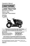
Steering
/
t
k
\
/
(1) 8olt
Steering Wheel Insert
Steering Wheel
(1) Large Flat Washer
JL
Steering
Wheel Adapter
l
t
t
t
L
L
_eedng
Steering Extension
Shaft
(1} Lock Washer
Boot
Seat
©
(1) Lock Washer
(1) Large Fiat Washer
(1) Seat
(1) Bolt
Keys
Key(e)
Oil
Drain
Extension
Slope
Sheet
'(our new tractor has been assembled at the factory with exception of those parts left
unassembled for shipping purposes. To ensure safe and proper operation of your tractor
all parts and hardware you assemble must be tightened securely. Use the correct tools
as necessary to ensure proper tightness,
TOOLS REQUIRED FOR ASSEMBLY
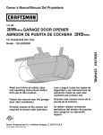
TO INSTALL STEERING WHEEL
A socket wrench set witl make assembly
ASSEMBLE EXTENSION SHAFT AND
easier, Standard wrench sizes are listed.
BOOT
(1) 5/16" wrench
Utility knife
1. Slide extension shaft onto lower steering
(2) 7/16" wrenches Tire pressure gauge
shaft.
(2) 1/2" wrenches
Pliers
2. Place tabs ofsteering boot over tab slots
in dash and push down to secure,
(1) 9/16" wrench
INSTALL STEERING WHEEL
When right or left hand is mentioned in this
3. Position front wheels of the tractor so
manual, itmeanswhenyouare intheoperating
they are pointingstraight forward.
position (seated behind the steering wheel).
4. Remove steering wheel adapter from
TO REMOVE
TRACTOR
FROM
steering wheel and slide adapter onto
CARTON
steering shaft extension,
UNPACK CARTON
5, Position steering wheeiso cross bars are
horizontal (left to right) and slide inside
• Remove all accessible loose partsand
boot and onto adapter.
parts cartons from carton.
6. Assemble large flat washer, lock washer,
o Cut along dotted lines on all four panbolt and tighten securely,
els of carton. Remove end panels and
7. Snap steering wheel insert into center of
lay side panels flat.
steering wheel.
• Check for any additional loose parts or
8. Remove protective materials from tractor
cartons and remove.
hood and grill.
BEFORE
REMOVING
TRACTOR
IMPORTANT: Check for and remove any
FROM SKID
staples inskid that may puncture tires where
tractor is to roll off skid,
TO CHECK BATTERY
1. Liftseat to raised position,
![ _;:_..-----_
Insert
NOTE: if this battery is putinto service after
* ---BOlt I( 11
month and year indicated on label (label is
located between terminals) charge battery
for minimum of one hour at 6-10 amps. (See
Laroe
F .t
"BATTERY" in Maintenance section of this
manual for charging instructions).
r T_-.--J)--__
\_-_{_,_/
---Steering
• For battery and battery cable installation
see "REPLACING BATTERY" in the
"'---_"_"y
Wheel
F,°,
_"Service and Adjustments" section in
:--_L._._.---_Steering
this manual.
' '
Boot
wo=.o,
_Adapter
n
Label
Steering
"<.:.-.
,
Shaft
"_',42
INSTALL SEAT
Adjust seat before tightening adjustment
knob.
1. Remove adjustment knob andflatwasher
securing seat to cardboard packing and
set aside for assembly of seat to tractor.
2, Pivot seat upward and remove from the
cardboard packing, Remove the cardboard packing and discard,
3. Place seat on seat pan so head ofshoulder bolt is positioned over large slotted
hole in pan.
4. Push down seat to engage shoUlder bolt
inslot and pullseattowards rear oftractor.
5. Pivot seat and pan forJvardand assemble
adjustment knob and flat washer loosely.
Do not tighten,
6, Lower seat into operating position and
sit in seat.
7. Slide seat until a comfortable positionis
reached which allows youto press clutch/
brake pedal all the way down.
8, Get off seat without moving its adjusted
position.
9. Raise seatand tighten adjustment knob
securely.
NOTE: You may now roll your tractor off
the skid. Fotlow the instructions below to
remove the tractor from the skid,
WARNING: Before starting, read, understand and follow all instructions in the
Operation section of this manual. Be sure
tractor is in a well-ventilated area. Be sure
the area in front of tractor is clear of other
people and objects.
TO ROLL TRACTOR OFF SKID (See
Operation
section for location
and
function of controls)
1. Raise attachment lift lever to its highest
position.
2. Release parking brake by depressing
clutch/brake pedal.
3. Place gearshift lever in neutral position,
4. Roll tractor forward off skid.
5. Remove banding holding the deflector
shield up against tractor.
Continue with the instructions that follow.
CHECK TIRE PRESSURE
The tires on your tractor were overinflated at
the factory for shipping purposes, Correct
tire pressure is important for best cutting
performance.
° Reduce tire pressure to PSI shown on
tires.
CHECK DECK LEVELNESS
For best cutting results, mower housing
should be properly leveled. See "TO LEVEL
MOWER" in the Service and Adjustments
section of this manual.
Seat Pan_ulder
CHECK FOR PROPER POSITION OF
ALL BELTS
See the figures that are shown for replacing motion and mower blade drive belts in
the Service and Adjustments section of this
manual, Verify that the belts are routed
correctly.
CHECK BRAKE SYSTEM
After you learn how to operate your tractor,
check to see that the brake is operating
properly. See "TO CHECK BRAKE" in the
Service and Adjustments section of this
manual.
FlatWasher
-..
Ad
9
_
CHECKLIST
Before you operate your new tractor, we
wish to assure that you receive the best
performance and satisfaction from this
Quality Product.
Please review the following checklist:
All assembly instructions have been
completed.
J No remaining loose parts in carton.
if Battery is propedy prepared and charged.
Seat is adjusted comfortably and tightened securely.
d" All tires are properly inflated. (For shipping purposes, thetires were overinflated
at the factory).
J Be sure mower deck is properly leveled
side-to-side/front-to-rear for best cutting
results. (Tires must be properly inflated
for leveling),
d" Check mower and drive belts. Be sure
they are routed propedy around pulleys
and inside all belt keepers.
J" Checkwiring. Seethat a_lconnectionsare
stillsecure andwires are propertyclamped.
While learning howto use your tractor, pay extra attention to the following impo rtant items:
_I Engine oil is at proper level.
d" Fueltank isfilled with fresh, clean, regular
unleaded gasoline.
J Become familiar with all controls, their
location and function. Operate them
before you start the engine.
J Besure brake system is insafe operating
condition.
J Be sure Operator Presence System and
Reverse Operation System (ROS) are
working propedy (See the Operation and
Maintenance sections in this manuat).
10
These symbols may appear on your tractor or in literature supplied with the product. Learn
and understand their meaning,
R
N
REVERSE
ENGINE
H
NEUTRAL
OFF
REVERSE
OPERATION
i ,.i
HIGH
ENGINE
LOW
ON
ENGINE
CHOKE
START
PARKING
FAST
CRAKE
SLOW
MOWER
IGNITION
SWITCH
MOWER
HEIGHT
LIFT
SYSTEM(_os_
LIGHTS
ON
FUEL
AI-rACHMENT
CLUTCH DISENGAGE_
BATTERY
REVERSE
ATTACHMENT
CLLrrC_t EHGAGEO
FORWARD
DANGER,
KEEP HANDS
AND FEET AWAV
CRD_E
KEEP
CONTROL
AReA
CLEAR
(SEE
FREE
(Autamatic
WHEEL
Models
only)
&
&
&
SAFetY
CLUTCHfSRAKE
PEDAL
SLOPE
RULES
HAZARDS
SECTION)
DANGER indicates a hazard which, if not avoided,
will result in death or serious injury.
WARNING indicates a hazard which, if not avoided,
could result in death or serious injury.
CAUTION
indicates a hazard which, if not avoided,
might result in minor or moderate injury'.
CAUTION when used without the alert symbol
indicates a situation that could result in damage
to the tractor and/or engine.
Failure to follow instructions
could result in serious injury or
death. The safety alert symbol
is used to identify safety information about hazards which can
result in death, serious injury
HOT SURFACES indicates a hazard which,
if not avoided, could result in death, serious injury
and/or property damage.
/_,
"_
FIRE indicates a hazard which, if not avoided,
could result in death, serious injury and/or
property damage,
and!or property damage.
11
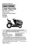
KNOW YOUR TRACTOR
READ THIS MANUAL AND SAFETY RULES BEFORE OPERATING YOUR TRACTOR
Compare the illustrations with your tractor to familiarize yourself with the locations of various controls and adjustments. Save this manual for future reference.
Attachment
Clutch Lever
Ignition
Switch
"ON"
Position
Lever
Plunger
Throttle!Choke
Control
Attachment
Lift Lever
Clutch/Brake
Pedal
'Height
_Adjustment
Indicator
Parking
Brake
r Shift
Lever
Our tractors conform to the applicable safety standards of the
American National Standards Institute.
ATTACHMENT CLUTCH LEVER - Used to
engage the mower blades, or other attachments mounted to your tractor.
ATTACHMENT LIFT LEVER- Used to raise,
lower, and adjust the mower deck or other
attachments mounted to your tractor,
CLUTCH/BRAKE PEDAL - Used for declutching and braking thetractor and starting
the engine.
LIFT LEVER PLUNGER- Used to release attachment liftleverwhen changing its position.
PARKING BRAKE - Locks clutch/brake
pedal into the brake position,
REVERSE OPERATION SYSTEM (ROS)
"ON"
POSITION - Allows operation of
mower deck or other powered attachment
while in reverse.
THROTFLE/CHOKE CONTROL- Used for
starting and controlling engine speed.
GEARSHIFT LEVER - Selects the speed
and direction of the tractor,
IGNITION SWITCH - Used for starting and
stopping the engine.
12
|
The operation of any tractor can result in foreign objects thrown into the eyes,!
which can result in severe eye damage. Always wear safety glasses or eye_
shields while operating your tractor or performing any adjustments or repairs,r
We recommend standard safety glasses or a wide vision safety mask wornI
over spectacles,
n
HOW TO USE YOUR TRACTOR
IMPORTANT: Leaving the ignition switch in
TO SET PARKING BRAKE
any position other than "STOP" will cause
the battery to discharge and go dead.
Your tractor is equipped with an operator
NOTE: Under certain conditions when
presence sensing switch. When engine
tractor is standing idle with the engine runis running, any attempt by the operator to
leavethe seat without first setting the parking ning, hot engine exhaust gases may cause
brake will shut off the engine.
"browning" of grass. To eliminate this possibility, always stop engine when stopping
1. Depress clutch/brake pedal into full
tractor on grass areas.
"BRAKE" position and hold.
2. Place parking brake lever in "ENGAGED"
_kCAUTION:
Always stop tractor composition and release pressure from
pletely, as described above, before Feaving
clutch/brake pedal. Pedal should remain
the operator's position.
in "BRAKE" position. Make sure parking
TO USE THROTTLE CONTROL
brake will hold tractor secure.
AttachmentClutch Always operate engine at full speed (fast).
Throttle!Choke
Lever"Engaged" - Operating engine at less than ful! speed
Control
Position
(fast) reduces engine's operating efficiency.
Ignition Key
• Full speed (fast) offers the best mower
performance.
Position
TO MOVE FORWARD AND BACKWARD
Position
The direction and speed of movement is
controlled by the gearshift lever.
Gear Shift
1. Start tractor with clutch/brake pedal
Lever
depressed and gearshift lever in neutral
Clutch/
position.
Brake
Parking
2. Move gearshift lever to desired position,
Pedal
Brake
3. Slowly release clutch/brake pedalto start
"Disengaged"
"Engaged"
movement.
Position
Position
IMPORTANT: Bring tractor to a complete
STOPPING
stop before shifting or changing gears.
Failure to do so will shorten the useful life
MOWER BLADES of your transaxle.
• To stop mower blades, move attachment
clutch control to the disengaged position.
GROUND DRIVE• Tostop ground drive, depress brake pedaI
all the way down.
• Move gearshift lever to neutral position.
ENGINE • Move throttle control to fast position.
NOTE: Failure to move throttle control to
fast position before stopping may cause
engine to "backfire".
• Turn ignition key to "STOP" position and
remove key, Always remove key when
leaving tractor to prevent unauthorized
use.
• Never use choke to stop engine.
13
TO ADJUST MOWER CUTTING HEIGHT
The position of the attachment lift lever
determines the cutting height.
° Grasp lift lever.
• Press plunger with thumb and move lever
to desired position.
The cutting height range is approximately
1-1/2 to 4". The heights are measured from
the ground to the blade tip with the engine
not running. These heights are approximate
and may vary depending upon soil conditions, height of grass and types of grass
being mowed,
• The average lawn shouId be cut to approximately2-1/2" during the cool season
and to over 3" during hot months. For
healthier and better looking lawns, mow
often and after moderate growth.
• For best cutting performance, grass over
6" in heightshould be mowed twice. Make
the first cut relatively high; the second to
desired height.
REVERSE OPERATION SYSTEM (ROS)
Your tractor is equipped with a Reverse
Operation System (ROS). Any attempt by
the operator to travel in the reverse direction
with the attachment clutch engaged will shut
off the engine unless ignition key is placed
in the ROS "ON" position,
_,WARNING:
Backing up with the attachment clutch engaged while mowing is
stronglydiscouraged, Tumingthe ROS"ON",
to allow reverse operation with the attachment clutch engaged, should only be done
when the operator decides it is necessary to
reposition the machine with the attachment
engaged. Do not mow in reverse unless
absolutely necessary.
USING THE REVERSE OPERATION
SYSTEM Only use if you are certain no children or
otherbystanders wiltenterthe mowing area.
1. Depress clutch!brake pedal all the way
down and hold.
2. With engine running, turn ignition key
counterclockwise to ROS "ON" position.
3. Look down and behind before and while
backing.
4. Move gear shift lever to reverse (R)
position and siowiy release clutch/brake
pedal to start movement.
5. When use of the ROS is no longer
needed, turn the ignitionkey clockwise
to engine "ON" position.
ROS "ON" Position
Engine"ON" Position
(Normal Operating)
TO OPERATE ON HILLS
_WARNING: Do not drive up or downhills
with slopes greater than 15° and do not
drive across any slope, Use the slope guide
provided at the back of this manual.
- Choosetheslowestspeed before starting
up or down hills.
• Avoid stopping or changing speed on hilts.
• If stopping is absolutely necessary, push
dutch/brake pedal quickly to brake position and engage parking brake.
• Move gearshift leverto lstgear. Be sure
you have allowed room for tractor to roll
slightly as you restart movement.
• To restart movement, slowiy release parking brake and clutch/brake pedal.
• Make atl turns slowly,
TO OPERATE MOWER
Your tractor is equipped with an operator
presence sensing switch. Any attempt
by the operator to leave the seat with the
engine running and the attachment clutch
engaged will shut off the engine. You must
remain fully and centrally positioned in the
seatto preventthe engine from hesitating or
cutting off when operating your equipment
on rough, rolling terrain or hills.
1. Select desired height of cut.
2. Start mower blades by engaging attachment clutch control.
14L
TO STOP MOWER BLADES
Disengage attachment clutch control.
_I_cAUTION:
Do not operate the mower
without either the entire grass catcher, on
mowers so equipped, or the deflector shield
in place.
AttachmentClutch
Throttle/Choke
Lever"Engaged"
Control
Position
Ignition Key
Position
Position
Gearshift
Lever
Clutch]
Brake
Pedal
"Disengaged"
Position
Parking
Brake
"Engaged"
Position
BEFORE STARTING THE ENGINE
CHECK ENGINE OIL LEVEL
The en! f_neinyour tractor has been shipped,
from the factory, already filled with summer
weight oil.
1. Check engine oil with tractor on Ievet
ground.
2. Remove oil fill cap/dipstick and wipe
clean, reinsert the dipstick and screw cap
tight, wait for a fewseconds, remove and
read oil level. If necessary, add oil until
"FULE' mark on dipstick is reached. Do
not overfill.
• For cold weather operation you should
change oil for easier starting (See the oil
viscosity chart inthe Maintenance section
of this manual).
• Tochange engine oil, seethe Maintenance
section in this manual.
ADD GASOLINE
• Fill fuel tank to bottom of filler neck. Do
not overfill. Use fresh, clean, regular
unleaded gasoline with a minimum of
87 octane. (Use of leaded gasoline will
increase carbon and lead oxide deposits
and reduce valve life). Do not mix oil with
gasoline. Purchase fuel in quantities that
can be used within 30 days to ensure fuel
freshness,
TO TRANSPORT
• Raise attachment lift lever to its highest.
, When pushing or towing your tractor,ensure gearshift lever is in neutral position.
• Do not push or tow tractor at more than
five (5) MPH.
NOTE: To protect hood from damage when
transporting yourtractoron atruck or atrailer,
ensure hood isclosed and secured to tractor.
Use an appropriate means of tying hood to
tractor (rope, cord, etc.).
TOWING CARTS AND OTHER ATTACHMENTS
Tow only the attachments that are recommended by and comply with specifications
of the manufacturer of your tractor, Use
common sense when towing. Too heavy of
a load, while on a slope, is dangerous. Tires
can lose traction with the ground and cause
you to lose control of your tractor,
_,CAUTION: Wipe offanyspitled oil or fuel.
Do not store, spill or use gasoline near an
open flame.
IMPORTANT: When operating in temperatures below32°F(0°C), use fresh, clean
winter grade gasoline to help ensure good
cold weather starting.
CAUTION: Alcohol blended fuels (called
gasohol or using ethanol or methanol) can
attract moisture which leads to separation
andformation ofacids during storage. Acidic
gas can damagethe fuelsystem of an engine
while in storage, To avoid engine problems,
the fuel system should be emptied before
storage of 30 days or longer. Drain the gas
tank, start the engine and let it run until the
fuel lines and carburetor are empty. Use
fresh fuel next season. See Storage Instructions for additional information. Never use
engine or carburetor cleaner products in the
fuel tank or permanent damage may occur.
15
TO START ENGINE
When starting the engine for the first time or
if the engine has run out of fuel, it wilt take
extra cranking time to move fuel from the
tank to the engine.
1, Siton seat in operating position, depress
clutch/brake pedal andset parking brake.
2. Ptace gear shift lever in neutral position.
3. Move attachment clutch to disengaged
position.
4, Move throttle control to choke position.
NOTE" Before starting, read the warm and
cold starting procedures below.
5, Insert key into ignition and turn key
clockwise to start position and release
key as soon as engine starts. Do not run
starter continuously for more than fifteen
seconds per minute, tf the engine does
not start after several attempts, move
throttle control to fast position, wait a
few minutes and try again. If engine still
does not start, move the throttle control
back to the choke position and retry,
WARM WEATHER STARTING
(50°F (10°O) and above)
6. When engine starts, move the throttle
control to the fast position.
• The attachments and ground drive
can now be used. If the engine does
not accept the load, restart the engine
and allow it to warm up for one minute
using the choke as described above.
COLD WEATHER STARTING
(50°F (10°C) and below)
6. When engine starts, leave throttle control
in choke position until engine warms up
and begins to run roughly. Once rough
running begins, immediately move the
throttle controlto the fast position. Engine
warm-up maytake from severalseconds
to several minutes (the colder the temperature, the longer the warm-up).
• The attachments can also be used
during the engine warm-up period.
NOTE: Ifata high altitude (above 3000 feet)
or in cold temperatures (below 32°F (0°C))
the carburetor fuel mixture may need to be
adjusted for best engine performance (see
"TO ADJUST CARBURETOR" inthe Service
and Adjustments section of this manual).
16
MOWING TIPS
- Tire chains cannot be used when the
mower housing is attached to tractor.
• Mower should be properly leveled for best
mowing performance. See "TO LEVEL
MOWER HOUSING" in the Service and
Adjustments section of this manual.
• The left hand side of mower should be
used for trimming,
• Drive sothat clippings are discharged onto
the area that has already been cut. Have
the cut area to the right of the tractor. This
will result in a more even distribution of
clippings and more uniform cutting.
• When mowing large areas, start byturning
to the right so that clippings will discharge
away from shrubs, fences, driveways,
etc. After one or two rounds, mow in the
opposite direction making left hand turns
until finished.
* If grass is extremely tall, it should be
mowed twice to reduce load and possible
fire hazard from dried clippings. Make
first cut relatively high; the second to the
desired height.
• Do notmowgrasswhen itiswet. Wetgrass
will plug mower and leave undesirable
clumps. Allow grass to dry before mowing.
. Always operate engine at full throttle
when mowing to ensure better mowing performance and proper discharge
of material. Regulate ground speed by
selecting a low enough speed to give the
mower cutting performance as welt as the
quality of cut desired.
• When operating attachments, select a
ground speed that will suit the terrain and
give best performance of the attachment
being used,
,,u
MAINTENANCE
SCHEDULE
BEFORE
EVERY
EVERY
F..&CR
8
25
58
100
HOURS
HOURS
HOURS
HOURS
USE
i
Check Brake Operation
....
V"
v" ........
v'
i/
v'
T CheckT!rePressure
R Ch_¢_ Operator Pi_sen_ & ROS Systems
A Check for Loose Fasteners
C Check/Replace Mower Blades
T Lubrication Chart
0 Check Battery Levet
R
E_#ERY ,,,, ,L EV£RY
Is"
V'
v'
v'
Cheek Mower Levelness
.....
v'
•
v'
v'
i
I_
i
Level
_
Oil
i
Check V-Belts
v*,_
3hanF_e Engine Oil (with, oil filter) i
Enqine
Oil.(without
J_
N_ 3lean Air F!,!!er
Inspect
Replace
i/
MuffleriSparkArreste[
F ns
.......
,,,
Spark Plug,
Air Filter
Paper
Cadddge
.......
Replace Fuel Fi!ter
1 - Change more otten when operating
in high ambient temperat_aras,
2 - Se_ice
mete often wher_ operating
GENERAL
_,
_'_
F to; ( f equ pped)
E Clean Encj[ne Cooling
Replace
v"
oil filter:
G .,c{ean A_r Screen,
N Replace Oi
v"
v'
Check Transaxle Cooling
_,hange
BEFORE
STORAGE
V#3
Clean Battery and Terminals
,_heck Eaq,.e
EVERY
SEASON
i/
,,,
unde_
e heavy
_oed Of
-3 _ RepIa0e blades more often when mowing
in sandy soil,
4 - Not mquirecl i! equipped
with maintenanoe-#e_
battery.
in dirty or (_usty condilior_s.
RECOMMENDATIONS
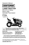
LUBRICATION CHART
The warranty on this tractor does not cover
items that have been subjected to operator
abuse or negligence.
To receive full value
from the warranty, operator must maintain
tractor as instructed in this manual.
(])Steering Pivot Bolts
Some adjustments
will need to be made
periodicaltyto
properly maintain your tractor,
At least once a season, check to see if
you should make any of the adjustments
described in the Service and Adjustments
section of this manual,
d) Spindle_f---/'_[_--(_)
Spindle
_Front -j
Wheel
Bearing
_hFer_nt
vv .
Bearing
e=:-_
j _
_
.._
x,.X _-_-J
.¢_£:"\h
....
_.
Zerk
/_
__'_ZerK
Steering" f--"/ _
Sector Gear F ( (-'_=_
Teeth
• At least once a year you should replace
the spark plug, clean or replace air filter,
and check blades and belts for wear. A
new spark plug and clean air filter assure
proper air-fuel mixture and help your engine run better and last longer.
It
[==___
LL
_'-'
CI
(_)General Purpose Grease
(_)Refer to Maintenance"ENGI
BEFORE EACH USE
1. Check engine oil level.
2. Check brake operation,
3. Check tire pressure.
4. Check operator presence and
ROS systems for proper operation,
5. Check for loose fasteners.
\_.
@ Engine
NE" Section.
IMPORTANT: Do not oil or grease the pivot
points which have special nylon bearings.
Viscous lubricants will attract dust and dirt
that will shorten the life of the self-lubricating
bearings. Ifyou feelthey must be Iubricated,
use only a dry. powdered graphite type
lubricant sparingly.
17
TRACTOR
Always observe safety rules when performing any maintenance.
BRAKE OPERATION
if tractor requires more than five (5) feet to
stop at highest speed in highest gear on a
level, dry concrete or paved surface, then
brake must be serviced. (See "TO CHECK
BRAKE" in the Service and Adjustments
section of this manual).
TIRES
• Maintain proper air pressure in all tires
(See the side of tires for proper PSI.)
• Keep tires free of gasoline, oil, or insect
control chemicals which can harm rubber.
" • Avoid stumps, stones, deep ruts, sharp
objects and other hazards that may cause
tire damage.
NOTE: To seal tire punctures and prevent
flat tires due to slow leaks,tire sealant may
be purchased from your local parts dealer.
Tire sealant also prevents tire dry rot and
corrosion.
OPERATOR PRESENCE SYSTEM AND
REVERSE OPERATION SYSTEM (ROS)
Be sure operator presence and reverse
operation systems are working properly. If
your tractor does not function as described,
repair the problem immediately.
• The engine should not start unless the
brake pedal is fully depressed, and the
attachment clutch control is in the disengaged position.
CHECK OPERATOR PRESENCE SYSTEM
° When the engine is running, any attempt
by the operator to leave the seat without
first settingthe parking brake should shut
off the engine.
• When the engine is running and the attachment clutch is engaged, any attempt
by the operator to leave the seat should
shut off the engine.
• The attachmentclutch should never oper• ate unless the operator is in the seat.
CHECK REVERSE OPERATION (ROS)
SYSTEM
• When the engine is running withthe ignition
switch inthe engine "ON" position and the
attachment clutch engaged, any attempt
by the operator to drive in reverse should
shut off the engine.
o Whenthe engine is runningwiththe ignition
switch in the ROS "ON" position and the
attachment clutch engaged, any attempt
by the operator to drive in reverse should
NOT shut offthe engine.
18
Ros "On"
Position
Engine +'On"Position
(Normal Operating)
BLADE CARE
For best results mower blades must besharp.
Replace worn, bent or damaged blades.
,_ CAUTION: Use only a replacement blade
approved bythe manufacturer of your tractor.
Using a blade not approved by the manufacturer of your tractor is hazardous, could
damage your tractor and void your warranty,
BLADE REMOVAL
1. Raise mower to highest position to allow
access to btades.
NOTE: Protectyour handswith gloves and/
or wrap blade with heavy cloth.
2. Remove blade bolt by turning counterclockwise.
3. Instal[ new blade with stamped "GRASS
SIDE" facing the ground,
IMPORTANT: To ensure proper assembly,
center hole in blade must align with star on
mandrel assembly.
4. Install and tighten blade bolt securely
(45-55 R+ Lbs./62-75 Nm)+
IMPORTANT: Special blade bolt is heat
treated,
Star
Center Hole
Blade Bolt
(Special) "-'1_""
Mandrel
Assembly
BATTERY
Your tractor has a battery chargingsystem
whichis sufficientfor normal usel However,
periodic chargingof the battery with an automotivecharger will extend its life.
• Keep battery and terminals clean.
• Keep battery bolts tight.
• Keep small vent holes open.
o Recharge at 6-10 amperes for I hour.
NOTE: The original equipment battery on
your tractor is maintenance free. Do not
attempt to open or remove caps or covers.
Adding or checking level of electrolyte is
not necessary.
TO CLEAN BATTERY AND TERMINALS
Corrosion and dirtonthe batteryandterminals
can cause the battery to "leak" power.
1. Remove terminal guard,
2. Disconnect BLACK battery cable first
then RED battery cable and remove
battery from tractor.
3. Rinse the battery with plain water and
dry,
4, Clean terminals and battery cable ends
with wire brush until bright,
5. Coat terminals with grease or petroleum
jelly.
6. Reinstall battery (See "REPLACING
BA-FFERY" in the Service and Adjustments section of this manual).
TRANSAXLE MAINTENANCE
Keep transaxle free from build-up of dirt and
chaff which can restrict cooling.
Do not attempt to clean transaxte while
engine is running or while the transaxle is
hot, To prevent possible damage to seals,
do not use high pressure water or steam to
clean transaxle,
V-BELTS
Check V-belts fordeterioration andwear after
100 hours of operation and replace if necessary. The belts are not adjustable. Replace
belts if they begin to slip from wear.
ENGINE
LUBRICATION
Only use high quality detergent oil rated with
API service classification SG-SL. Select the
oil's SAE viscosity grade according to your
expected operating temperature.
NOTE: Although multi-viscosity oils (5W30,
10W30 etc.) improve starting incold weather,
they will result in increased oil consumption
when used above 32°F/0°C, Check your
engine oil level morefrequentlyto avoid possible enginedamagefrom running Iowon o&
Changethe oil after every 50 hours of operation or at least once a year if the tractor is
not used for 50 hours in one year,
Checkthe crankcase oil level before starting
the engine and after each eight (8) hours
of operation. Tighten oil fil! cap/dipstick
securely each time you check the oil level.
TO CHANGE ENGINE OIL
Determine temperature range expected
before oil change. All oil must meet API
service classification SG-SL,
1, Ensure tractor is on level surface,
2. Oil will drain more freely when warm.
3. Catch oil in a suitable container.
4. Remove oil fill cap/dipstick. Be careful
notto allow dirt to enter the engine when
changing oil.
CAUTION: If engine has been operated for
an extended period of time immediately prior
to draining oil, oil will be hot,
Drain Hold)/
1
in Plug
_Oil Drain_ I
Extension_
5. Slide oil drain extension under oil drain
hole (drain hole may be flush with or
protrude from engine block side wall),
6. Ensure back face of oil drain extension
is flush with engine side wall.
7. Ensure bottom lip of oil drain extension
is lined up with bottom of oil drain hole.
8. Position a container to catch oil directly
under front end of oil drain extension,
9, Slide a 1/2" (12 point) socket mounted
on an extension onto oil drain plug.
10. Loosen plug while holding the oil drain
extension firmly in place.
t 1.Drain oil into container.
12. After oil has drained completely, reinstall
oil drain plug. (Do not tighten more than
13 Ft. LbsJ18 Nm,)
13. Refill enginewith oilthrough oilfill dipstick
tube, Pour slowly. Do not overfill. For
approximate capacity see "PRODUCT
SPECIFICATIONS"
section of this
manual,
14.Use gauge on oil fill cap/dipstick for
checking level. Ensure dipstick cap is
tightened securely for accurate reading.
Keep oil at"FULE' line on dipstick. Tighten
cap ontothe tubesecurely when finished.
19
AIR FILTER
Your engine will not run properly using a
dirty air filter. Service air cleaner more often
under dusty conditions. See engine manual.
CLEAN AIR SCREEN
Air screen mustbe kept free of dirt and chaff
to prevent engine damage from overheating.
Clean with awire brush or compressed airto
remove dirt and stubborn dried gum fibers.
ENGINE COOLING SYSTEM
Debris may clog the engine's air cooling
system. Remove blower housing and clean
the area shown to prevent overheating and
engine damage.
Clean
And
ebns
MUFFLER
Inspect and replace corroded muffler and
sparkarrester (ifequipped)as itcouldcreate
a fire hazard and/or damage.
SPARK PLUG(S)
RepIace spark ptug(s) at the beginning of
each mowing season or after every 100
hours of operation, whichever occursfirst.
Spark plug type and gap setting are shown
in "PRODUCT SPECIFICATIONS" section
o/this manual,
20
IN-LINE FUEL FILTER
The fuel filter should be replaced once each
season. If fuelfilter becomes clogged, obstructing fuel f!owto carburetor, replacement
is required.
!. With engine cool, remove filter and plug
fuel line sections.
2. Place newfuel filter in position infuel line
with arrow pointing towards carburetor.
3. Ensure there are no fuel line leaks and
clamps are properly positioned.
4, ]mmediatelywipe up anyspilled gasoline.
amp
CLEANING
• Clean engine, battery, seat, finish, etc.
of all foreign matter.
• Keep finished surfaces and wheels free
of all gasoline, oil, etc.
• Protect painted surfaces with automotive type wax.
We do not recommend using a garden
hose or pressure washer to clean your
tractor unless the engine and transmission are covered to keep water out. Water
in engine or transmission will shorten
the useful life of your tractor. Use compressed air or a ]eaf blower to remove
grass, leaves and trash from tractor and
mower,
WARNING:
TO AVOID SERIOUS INJURY, BEFORE PERFORMING ANY SERVICE OR
ADJUSTMENTS:
1.
2.
3.
4.
5.
6.
Depress clutch/brake
pedal fully and set parking brake.
Place gearshift lever in neutral position,
Place attachment clutch in"DISENGAGED"
position.
Turn ignition key to "STOP" and remove key.
Make sure the blades and all moving parts have completely stopped.
Disconnect spark plug wire from spark plug and place wire where it cannotcome
in contact with plug,
TO REMOVE MOWER
Mower will be easier to remove from the
right side of tractor.
1. Place attachment clutch in "DISENGAGED" position,
2. Move attachment lift lever forward to
lower mower to its lowest position,
3, Roll belt off engine pulley.
4. Remove small retainer spring, and
remove clutch spring off pulley bolt.
5. Remove large retainer spring, slide
collar off and push housing guide out
of bracket,
6. Disconnect anti-sway bar from chassis
bracket by removing retainer spring.
7. Disconnect suspension arms from rear
deck brackets by removing retainer
springs.
& Disconnect front links from deck by
removing retainer springs.
9. Raise lift lever to raise suspension
arms. Slide mower out from under tractor.
IMPORTANT: If an attachment other than
the mower deck is to be mounted on the
tractor, remove the front links and hook
the clutch spring Into square hole in frame.
TO INSTALL MOWER
1. Raise attachment lift lever to its highest
position.
2. Slide mower under tractor with deflector shield to right side of tractor.
3. Lower lift lever to its lowest position.
4. Connect front links to mower deck and
secure with retainer springs.
5. Connect suspension arms to rear deck
brackets and secure with retainer
springs.
6. Connect anti-sway bar to chassis
bracket and secure with retainer
spring.
7. Push clutch cable housing guide into
bracket, slide collar onto guide and
secure with large retainer spring.
8. Place fiat washer and clutch spring on
idler pulley bolt and secure with small
retainer spring.
9. Install belt onto engine pulley.
Smell Retainer:
Clutch Sprin!
Clutch
Arms
Retainer
Anti-Sway
LRetainer Springs
(Both Sides)
Bracket
21
TO LEVEL MOWER HOUSING
Check adjustment on right side of tractor.
Measure distance "D" directly in front of
Adjust the mower while tractor is parked
and behind the mandrel at bottom edge of
on level ground or driveway. Make sure
mower housing as shown,
tires are properly inflated (See the sides
• Before making any necessary adjustof tires for proper PSI). If tires are over or
merits, check that both front links are
underinflated, you wilt notproperly adjust
equal in length.
your mower.
• If links are not equal in length, adjust
SIDE-TO-SIDE ADJUSTMENT
one link to same length as other link.
• Raise mower to its highest position.
To lower front of mower loosen nut "E"
° At the midpoint of both sides of mower,
on both front links an equal number of
measure height from bottom edge of
turns.
mower to ground. Distance '_' on both
° When distance "D" is t/8" to 1/2"
sides of mower should be the same or
lower at front than rear, tighten nuts "F"
within I/4" of each other,
against trunnion on both front links.
• if adjustment is necessary, make adjust- °;. To raise front of mower, loosen nut
ment on one side of mower only.
"F" from trunnion on both front links.
° To raise one side of mower, tighten )ift
Tighten nut "E" on both front links an
link adjustment nut on that side,
equal number of turns. The two front
• To lower one side of mower, loosen lift
links must remain equal in length,
link adjustment nut on that side.
When distance "D" is 1/8" to 1/2" lower
NOTE: Each full turn of adjustment nut
at front than rear, tighten nut "F" against
will change mower height about 1/8".
trunnion on both front links.
t
Recheck side-to-side adjustment.
BottomEdge of
BottomEdge of
Mowerto Ground
Mowerto Ground
\
/
BOTH
MUST
FRONT-TO-BACK ADJUSTMENT
IMPORTANT: Deck must be level side-toside, If the following front-to-back adjustment is necessary, be sure to adjust both
front links equally so mower will stay
level side-to-side.
To obtain the best cutting results, the
mower housing should be adjusted so
that the front is approximately 1/8" to 1/2"
lower than the rear when the mower is in
its highest position.
22
FRONT
PLATE
BE EQUAL
LINKS
IN LENGTH
TO REPLACE
BELT
MOWER
BLADE
TO REPLACE MOTION DRIVE BELT
Park the tractor on level surface, Engage
parking brake. For assistance, there is a
belt installation guide decal on bottom side
of left footrest.
DRIVE
The mower blade drive belt may be replaced
without tools. Park the tractor on level surface.
Engage
parking
BELT REMOVAL
brake.
BELT REMOVALt, Remove mower (See "TO REMOVE
MOWER" in this section of manual).
NOTE: Observe entire motion drive belt
and position of all belt guides and keepers.
2, Remove bett from stationary idler and
clutching idler.
3, Remove belt downward from around
engine pulley.
4. Pull belt slack toward rear of tractor.
Remove belt upwards from transax{e
pulley by deflecting belt keepers,
5. Remove belt from center span keeper
and pull belt away from tractor,
BELT INSTALLATION 1. Carefully work new belt down between
transaxle belt keepers and onto the
input pulley.
2. Slide belt into the center span keeper.
3. Pul! belt toward front of tractor and roll
around the top groove of engine pulley.
4, Install belt through stationary idler and
clutching idler,
5. Make sure belt is in all pulley grooves
and inside alebelt guides and keepers.
6, Install mower (See "TO INSTALL
MOWER" in this section of manual).
-
1. Remove mower from tractor (See "TO
REMOVE MOWER" in this section of
manual).
2. Work belt off both mandrel pulleys and
idler pulleys.
3. Pull belt away from mower.
BELT INSTALLATION
-
I.
Work belt around both mandrel pulleys
and idler pulleys
2. Ensure belt is in all pulley grooves and
inside all belt guides.
3. Install mower (See "To install Mower" in
this section of this manual).
Idler Pulleys
Pulley
TO CHECK BRAKE
If tractor requires more than five (5) feet to
stop at highest speed in highest gear on a
level, dry concrete or paved surface, then
brake must be serviced.
You may also check brake by:
1. Park tractor on a level, dry concrete or
paved surface, depress clutch!brake
pedal all the way down and engage
parking brake,
2. Place gear shift lever in neutral position.
The rear wheels must lock and skid when
you try to manually push the tractor forward.
If the rear wheels rotate, then the brake
needs to be serviced. Contact a Sears or
other qualified service center.
Engine
Pulley-_
Clutching_
Idler
StationaryJ
Center Span
Keeper
23
;ru_n_x_
TRANSAXLE GEAR SHIFT LEVER NEUTRAL ADJUSTMENT
The transaxle should be in neutral when the
gear shift lever is in neutral (N) (lock gate)
position. The adjustment is preset at the
factory; however, if adjustment is needed,
proceed as follows:
1. Ensure transaxle is in neutral (N).
NOTE: When the tractor rear wheels move
free[y, the transaxle is in neutral.
2. Loosen adjustment bolt in front of the
right rear wheel.
3. Position the gear shift Iever inthe neutral
(N) position.
4+ Tighten adjustment bolt securely,
NOTE: If additional clearance is needed to
get to adjustment bolt, move mower deck
height to the lowest position.
GearshiftLever
FRONT WHEEL TOE-IN/CAMBER
Your new tractor front wheel toe-in and
camber is set at the factory and is normal.
The front wheel toe-in and camber are not
adjustable. If damage has occurred to
affect the factory set front wheel toe-in or
camber, contact a Sears or other qualified
service center.
TO START ENGINE WITH A WEAK BATTERY
_WARNING:
Lead-acid batteries generate explosive gases, Keep sparks, flame
and smoking materials away from batteries.
Always wear eye protection when around
batteries.
Ifyour battery istoo weak to start the engine,
it should be recharged, (See "BATTERY" in
the MAINTENANCE section of this manual).
If "jumper cables" are used for emergency
starting, follow this procedure:
IMPORTANT: Your tractor is equipped with
a 12voltsystem. The othervehicle must also
be a 12 volt system. Do not use your tractor
............
battery to start other vehicles. ................................
TO ATTACH JUMPER CABLES 1. Connect one end ofthe RED cab[etothe
POSITIVE (+) terminal of each battery(ANeutral
Lock
B), taking care notto short against tractor
chassis.
AdjustmentBolt
Gate
2, Connect one end of the BLACK cable
TO REMOVE WHEEL FOR REPAIRS
to the NEGATIVE (-) terminal (C) of fully
1. Block up axle securely.
charged battery.
2. Remove axle cover, retaining ring and 3+ Connect the other end of the BLACK
washers to allow wheel removal (rear
cable (D) to good chassis ground, away
wheels have asquare key- Do not lose).
from fuel tank and battery.
3, Repair tire and reassemble.
NOTE: On rearwheels only: align grooves in TO REMOVE CABLES, REVERSE ORDERrear wheel hub and axle. Insert square key. 1, BLACK cable first from chassis and then
from the fully charged battery.
4. Replace washers and snap retaining ring
2, RED cable fast from both batteries.
securely in axle groove.
5, Replace axle cover.
NOTE: To seal tire punctures and prevent
flat tires due to slow leaks, purchase and
use tire sealantfrom Sears. Tire sealant also
preventstire dry rot and corrosion.
Washers
Retaining
Weak or Dead
Battery
Ring \\\
Axle Cover
'_Square
Key (Rear
Wheel Only)
24
FullyCharged
Baltery
REPLACING BATTERY
n_asWbARNING:Do not short battery termF
yallowing awrench or any other object
to contact both terminals at the same time.
Before connecting battery, remove metal
bracelets, wristwatch bands, rings, etc.
Positive terminal must be connected first to
preventsparking from accidental grounding.
1, Lift seat pan to raised position.
2. Remove terminal cover.
3. Disconnect BLACK battery cable then
RED battery cable and carefully remove
battery from tractor.
4. Install new batte_ with terminals in same
position as old battery.
5. Reinstall terminal cover.
6, First connect RED battery cable to positive (+) battery terminal with bolt and nut
as shown. Tighten securely,
7. Connect BLACK grounding cable to
negative (-) batteryterminal with remaining bolt and nut. Tighten securely
8, Lower seat pan,
Terminal
Cover
Positive
(Red)
Cable
Nut
Bolt
Negative
(Black)
Cable
TO REPLACE FUSE
Replace with30 amp automotive-type plugin fuse. The fuse holder is located behind
the dash.
TO REMOVE HOOD AND GRILL
ASSEMBLY
1. Raise hood.
2. Unsnap headlight wire connector.
3. Stand in front of tractor. Grasp hood at
sides, tilt toward engine and lift off of
tractor.
4, When replacing hood, ensure to reconnect the headlight wire connector,
Headlight
Connector
Wire
ENGINE
TO ADJUST THROTTLE CONTROL
CABLE
The throttle control has been preset at
the factory and adjustment should not be
necessary Check adjustment as described
below before loosening cable. If adjustment
is necessary, see engine manual.
TO ADJUST CHOKE CONTROL
The choke control has been preset at
the factory and adjustment should not be
necessary. If adjustment is necessary, see
engine manual.
TO REPLACE HEADLIGHT BULB
1, Raise hood.
2, Remove bulb holder from the hole in the
backside of the grill,
3. Replace bulb in holder and install bulb
holder securely back intothe hole in the
backside of the grill,
4. Close hood.
TO ADJUST CARBURETOR
Your carburetor has been presetatthe factory
and adjustment should not be necessary,
However, minor adjustment may be required
to compensate for differences in fuel, temperature, altitude or load. If the engine does
need adjustment, see engine manual.
INTERLOCKS AND RELAYS
Loose or damaged wiring may cause your
tractor to run poorly, stop running, or prevent
it from starting.
- Check wiring.
25
Immediately prepare your tractor for storage
at the end of the season or if the tractor will
not be used for 30 days or more.
_,WARNING:
Never store the tractor with
gasoline in the tank inside a building where
fumes may reach an open flame or spark.
Allow the engine to cool before storing in
any enclosure,
TRACTOR
Remove mower from tractor for winter storage. When mower is to be stored for a period
of time, clean it thoroughlY, remove all dirt,
grease, leaves, etc. Store in aclean, dry area.
1. Clean entire tractor (See "CLEANING" in
the Maintenance section of this manual).
2. Inspect and replace belts, if necessary
(See belt replacement instructions in the
Service and Adjustments section of this
manual).
3. Lubricate as shown in the Maintenance
section of this manual.
4. Be sure that all nuts, bolts and screws
are securely fastened. Inspect moving
parts for damage, breakage and wear.
Replace if necessary.
5+ Touch up all rusted or chipped paint
surfaces; sand lightly before painting,
BATTERY
• Fully charge the battery' for storage.
• After a period of time in storage, battery
may require recharging.
• To help prevent corrosion and power
leakage during long periods of storage,
battery cables should be disconnected
and battery cleaned thoroughly (see "TO
CLEAN BATTERY AND TERMINALS" in
the Maintenance section of this manual).
• After cleaning, leave cables disconnected
and place cables where they cannot come
in contact with battery terminals.
• If battery is removed from tractor for
storage, do not store battery directly on
concrete or damp surfaces.
26
ENGINE
FUEL SYSTEM
IMPORTANT: It is important to prevent
gum deposits from forming in essential fuel
system parts such as carburetor, fuel hose,
or tank during storage, Also, alcohol blended
fuels (called gasohol or using ethanol or
methanol) can attract moisture which leads
to separation and formation of acids during
storage. Acidic gas can damage the fuel
system of an engine while in storage.
• Empty the fuel tank by starting the engine
and letting it run until the fuel lines and
carburetor are empty.
• Never use engine or carburetor cleaner
products in the fuel tank or permanent
damage may occur.
• Use fresh fuel next season.
NOTE: Fuel stabilizer is an acceptable alternative in minimizing the formation of fuel
gum deposits during storage. Add stabilizer
to gasoline in fuel tank or storage container.
Always fogowthe mixratio found on stabilizer
container. Run engine at least 10 minutes
afteradding stabilizer to allowthe stabilizer to
reach the carburetor. Do not empty the gas
tank and carburetor if using fuel stabilizer.
ENGINE OIL
Drain oil (with engine warm) and replace
with clean engine oil. (See "ENGFNE"in the
Maintenance section of this manual).
CYLINDER(S)
1. Remove spark p_ug(s).
2. Pourone ounce ofoilthrough spark plug
hole(s) into cylinder(s).
3. Turn ignition keyto "START" position for
a few seconds to distribute oil.
4. Replace with new spark ptug(s).
OTHER
• Do not store gasoline from one season to
another.
, Replaceyour gasoline can ifyour can starts
to rust. Rust and/or dirt in your gasoline
will cause problems.
• If possible, store your tractor indoors and
cover itto give protection from dust anddirt,
• Cover your tractor with a suitable protective cover that does not retain moisture.
Do not use plastic. Plastic cannot breathe
which allows condensation to form and will
cause your tractor to rust.
IMPORTANT: Never cover tractor while
engine and exhaust areas are still warm.
TROUBLESHOOTING CHART:
See appropriate section in manual unless directed to Sears service center
PROBLEM
Will not start
CAUSE
Out of fuel,
t
Fill fuel tank,
2
Engine not "CHOKED _ properly.
2
See "TO START ENGINE'* in
Operation section.
3
Engine flooded.
4
Bad spark plug.
4
Reptace spark plug,
5
Dirty air filter.
5
Clean!replace
6
Dirty fuel filter,
6
Replace fuei filter.
7
Water in fuel.
7
Empty fuel tank and carburetor,
refill tank with fresh gasoline and
replace fuel filter.
8
Loose or damaged wiring.
8
Check all wiring.
9
Carburetor
9
See "To Adjust Carburetor" in
Service and Adjustments section.
10
Contact a Sears or other qualified
service center.
Wait several minutes before
attempting to start.
out Ofadjustment.
Engine valves out of adjuslment.
air filter.
1
Dirty air filter,
1
Clean/replace
2
Bad spark plug.
2
Replace spark plug.
3
Weak or dead battery.
!3
Recharge
4
Dirty fuel filter,
_4
Replace fuel filte£
5
Stale or dirty fuel,
_5
Empty fuel tank and refill tank wifl
fresh, clean gasoline.
6
Loose or damaged wiring,
i6
Check all wiring.
Carburetor
_7 [ See "To Adjust Carburetor" in
Service and Adjustments section,
7
out of adjustment.
Engine valves out of adjustment.
Engine will not
turn over
........
1
10i
Hard to start
C()RRECTION
air fi_tef.
or replace battery.
Contact a Sears or other qualified
service center.
I
Clutch)brakepedal notde;ressed. 1
Depress clutch/brake
2
Attachment
2.
Disengage
i3
clutch is engaged.
pedal.
attachment
clutch.
Weak or dead battery.
3
Recharge or replace battery.
4
Blown fuse,
4
Rep[ace fuse,
5
Corroded
5
Ctean battery terminals.
6
Loose or damaged wiring,
6
Check all wiring.
7
Faulty ignition switch.
7
Check/replace
ignition switch.
8
Faulty solenoid or starter.
8
Check/replace
solenoid
9
Faulty operator
switch(es).
9
Con!act a Sears or other qualified
service center.
battery terminals.
presence
27
or starter.
TROUBLESHOOTING CHART:
See appropriate section in manual unless directed to Sears service center
CAUSE
Engine clicks but
will not start
Loss of power
CORRECTION
1
Weak or dead battery.
1
Recharge or replace battery,
2
Corroded battery terminals,
2
Clean battery terminals,
3
Loose or damaged wiring,
3
Check all wiring,
4
Faulty solenoid or starter.
4
Check!replace
1
Cutting too much grass!too fast,
1
Raise cutting height/reduce
speed.
2
Throttle in "CHOKE" position,
2
Adjust throttle control.
3
Build-up of grass, leaves and
trash under mower.
3
Clean underside of mower
housing.
4
Dirty air filter.
4
Clean/replace
5
Low oil level/dirty oil,
5
Check oil level/change
6
Faulty spark plug.
6
Clean and regap or change spark
plug.
7
Dirty fuel filter.
7
Replace fuel filter,
8
Stale or dirty fuel.
8
Empty rue] tank and refiU tank with
fresh, clean gasoline.
9
Water in fuel.
9
Empty fuel tank and carburetor,
refilt tank with fresh gasoline and
replace fuel filte£
10 ! Spark plug wire loose.
10
Connect and tighten spark plug
w_re.
11
Dirty engine air screen/fins.
11
Clean engine air screen/fins,
12
Dirty/clogged
12
Clean/replace
131 Loose or damaged wiring,
13
Check all wiring.
14i
Carburetor
14: See "To Adjust Carburetor" in
Service and Adiustments section.
1el
Engine valves out of adjustment.
muffler,
out of adjustment,
solenoid or starter.
air filter.
oil.
mufflen
151 Contact a Sears or other qualified
service center.
..... ,,,,,
.......
Excessive
vibration
1
Worn. bent or loose blade.
1
Replace b_ade. Tighten blade bolt,
2
Bent blade mandrel
2
Contact a Sears or other
Loosetdamaged
3
Tighten loose part(s).
Replace damaged parts.
1
Check wiring, switches and
connections. If not corrected,
contact a Sears or other
qualified service center.
Engine continues to 1
run when operator
leaves seat with
attachment clutch
engaged
part(s).
Faulty operator-safety
control system.
presence
28
TROUBLESHOOTING CHART:
See appropriate section in manual unless directed to Sears service center
PROBLEM
Poor cut
cutting
CAUSE
uneven
Mower
blades
not rotate
Poor
will
grass
1
2
CORRECTION
Worn, bent or loose blade.
1
Mower deck not level,
2
Level mower deck.
3
Buildup of grass, leaves, and
trash under mower.
3
Clean underside of mower
housing.
4
Bent blade mandrel,
5
Clogged mower deck vent from
build-up of grass, leaves, and
trash around mandrels.
1
Obstruction
2
Worn/damaged
2
Replace mower drive belt.
3
Frozen idler pulley.
3
Replace idler pulley.
4
Frozen blade mandrel.
4
Contact a Sears or other
qualified service center.
1
Engine speed too slow.
1
Place throttle control in "FAST"
position.
2
Travel speed too fast,
2
Shift to slower speed.
3
Wet grass.
3
Allow grass to dry before mowing
4
Mower deck not level.
4
Level mower deck.
5
Low/uneven
5
Check tires for proper PSI.
6
Worn, bent or loose blade.
6
Replace/sharpen
blade bolt.
7
Buildup of grass, leaves and
trash under mower.
7
Clean underside of mower
housing.
8
Mower drive belt worn.
8 ! Replace mower drive belt.
9
Blades improperly
9 i Reinstall blades sharp edge down
10
Improper blades used.
11
Clogged mower deck vent holes
11
from buildup of grass, leaves, and
trash around mandrels.
C(ean around mandrels
open vent holes,
1
2
Light switch is _OFF".
1
Turn light switch "ON".
Bulb(s) or lamp(s)
2
Replace bulb(s) or lamp(s).
3
Faulty light switch,
3
Check/replace
4
Loose or damaged wiring.
4
Check wiring and connections.
5
Blown fuse.
5
Replace fuse.
1
Bad battery cell(s).
1
Replace battery.
2
Poor cable connections.
2
Check/clean
3
Faulty regulator (if so equipped).
3
Replace regu{ator.
4
Faulty alternator,
4
Replace alternator.
j4
5
in clutch mechanism,
mower drive belt.
installed.
Contact a Sears or other
qualified service center.
Clean around mandrels to
open vent holes.
Remove obstruction.
discharge
tire air pressure,
Replace blade. Tighten blade bob
10
btade. Tighten
Replace with blades listed in
this manual.
to
............
.,_,,,
,,, _,,_,,,
Headlight(s) not
working
(if so equipped)
Battery
charge
will
not
burned out.
29
light switch.
all connections.
TROUBLESHOOTING CHART:
See appropriate section in manual unless directed to Sears service center
PROBLEa
.........
'CAUSE
Loss of drive
..........................
COrReCTiON....
1
Debris on steering
equipped),
2
plate (if
1
see "¢;LEANiNG" in the
maintenance section.
Motion drive belt worn, damaged,
or broken,
2
Replace motion drive belt,
;3
Axle key missing.
3
install axlekey at rear wheel. See
"TO REMOVE WHEEU' in the
Service end Ad,_ustments section.
1
Engine throttle control not set
between half and full speed (fast)
position before stopping engine,
1
Move throttle control between
half and full speed (fast) position
before stopping engine.
1
Reverse operationsystem (ROS)
is not "ON" whilemower or other
attachmentiSengaged,
1
Turnignition key to ROS "ON"
position. See Operation section.
,
Engine "backfires"
when
turning
"OFF"
engine
Engine dies when
tractor is shifted
into reverse
,,,,,,,
NEED HORE HELP?
You'U find the answez and more on managemyhome.com
• Find this
and all your
other
product
manuals
onJ.ine.
- Gel: answers from our team of home experts,
• Get a personalized
• Find information
manage
maintenance
and tools
plan for your
to help with
home.
home projects.
home
brought to you by Sears
3O
................
- for free!
SUGGESTED
GUIDE
FOR SIGHTING
SLOPES
FOR SAFE OPERATION
ONLY RIDE UP AND DOWN HILL,
NOT ACROSS HILL
t5 DEGREES MAX.
WARNING:
To avoid serious injury, operate your tractor up and
down
face of
slopes,
never across
the face,
Do nottomow
slopes the
greater
than
15 degrees.
Make turns
gradually
prevent
tipping or loss of control. Exercise extreme caution when
changing direction on slopes,
1, Fold this page along dotted line indicated above.
2. Hold page before you so that its left edge is vertically parallel to a tree
trunk or other upright structure.
3. Sight across the fold in the direction of hill slope you want to measure.
4. Compare the angle of the fold with the slope of the hill.
Garantfa ..........................................................
Reglas de Seguridad ......................................
Especificaciones del Producto ........................
Montaje/Pre Operaci6n ...................................
Operaci6n .......................................................
Mantenimiento ................................................
32
33
36
38
41
47
Programa de Mantenimiento .......................... 47
Servicio y Ajustes ........................................... 5_
Almacenamiento ............ _................................ 56
Identificaci#n de Problemas ........................... 57
Servicio Sears ............................. Contraportada
GarantJa para equipos tractores Craftsman
GARANTIA COMPLETA DE CRAFTSMAN
PeR DOS AthOS desde Jafecha de compra, todas las partes no sustituib[es de este equipo tractor est_n
garantizadas contra cualquier defecto de material o mane de obra. Una parte no sustituible defectuosa
!'ecibird reparaci6n o reemplazo gratuito en casa si Ja reparacibn es imposible.
PeR CINCO AtqOS desde la fecha de compra, el bastidor y el eje delantero de este equipo tractor est_n
garantizados COntra cualqu{er defecto de material o mane de obra. Un bastidor o eje defantero defectuoso
recibir& reparaci6n o reemplazo gratuito en casa si Ia reparaci6n as imposible.
DURANTE 90 DiAS desde la fecha de compra, la bater{a (una parts sustituible) de este equipo tractor
est& garantizada contra cualquier defecto de material o mane de obra (nuestra prueba comprueba qua no
contendr,_ carga). Una bateda defectuosa recibir_ un reemplazo gratuito en casa.
GARANT|A LIMITADA
est_ provisto)
DE PeR VIDA AD|CIONAL
en el EJE DELANTERO
DE HIERRO
COLADO
(si
DURANTE EL TIEMPO EN QUE SE USE per el propietario original despu6s del quinto aSo a partir de ]a
fecha de compra, el eje delantero de hierro colado (si est,. provisto) de este equipo tractos est_ garantizado
contra cualquier defecto de material o mane de obra. Con el comprobante de compra, un eje delantero de
hierro colado recibir& un reemplazo gratuito en casa.
SERVIC|O
DE GARANTiA
Para conocer los detaI]es de la cobertura de garant[a para obtaner una reparaci6n
Iiame at 1-800-659-5917
6 visite el sitio web: www, craftsman.com
o reempIazo
En redes los cases anteriores, si el reemplazo es imposible, el equipo tractor ser_, sustituido
el mismo modelo o uno equivalante.
Toda la cobertura de garantia anterior set& nula sieste
servicios comerciales o si se alquila aotra persona,
gratuJto,
sin cargo con
equipo tractor se utiliza alguna vez para brindar
Esta garantia cubre 0NICAMENTE
defectos de material y mano de obra. La cobertura de garanlia NO
incluye:
•Partes
sust_uibles (excepto ta bateria) que se puedan desgastar per eI use normaI dentro del pedodo de
garantia lncluso, pore sin limitarse a, cuchillas, bujias, fittros de aire, correas y filtros de aceite.
• $ervicios de mantenimiento est&ndar, ¢ambios de aceite o afinaciones,
.
•
Reemplazo o reparaci6n de neum_.ticos per pinchazos oausados per objetes externos come clavos,
espinas, tocones o vidrios,
Reemplazo o reparaci6n de neum&ticos o ruedas per desgaste normal, accidentes o per operaci6n o
mantenimiento incorrectos.
•
Reparaciones necesadas per abuse del operador incluso, pero sin Iimitarse a, daSos causados per
remolcar objetos que suparen la capacidad deI equipo tractor, chocar contra objetos que doblen el
basiidor, el ensamble del eje o e! cig0e6aI o sobrepasar la velocidad del motor,
• Reparaciones necesarias per negligencia del operador, incluso (pore sin limitarse a clio) da6os el6ctricos
y mec&nicos causados per e[ almacenamiento incorrecto, per no usar el grade y la cantidad correctos de
aceite de motor, per no mantener del muelle tibre de residues inflamablas o per no manlener el equipo
tractor de acuerdo con las instrucciones qua confiene el manual de] operadoro
• Umpieza o reparaciones
del motor (sistema de combustible)
cuando se determina que se us6
combustible contaminado y oxidado (sarro). En general, el combustible debe usarse dentre de los 30
dlas posteriores a su compra.
• Deterioro y desgaste normal de los acabados exteriores o sustituci6n de r6tulos de productos,
Esta garantla Ie olorga detaches legales especificos, y usted tambi6n puede tenor otros dereehos que
varlan de un estado a otro.
Sears Brands Management Corporation, Hoffman Estates, IL 60179
32
_PELIGRO:
Esta Maquina cortadora es capaz de amputar tas manosy los pies y de lanzar
objetos, si no se observan las instrucciones de seguridad siguientes se pueden producir
lesiones graves o la muerte.
• No maneje ta mAquina si no tiene la trampa
_DVERTENCIA:
Siempre desconecte el alampara c_sped completa, la canaleta de descarga
bre de la bujia y p6ngalo donde no pueda entrar
u otros dispositivos de seguridad en su lugar
en contacto con [a bujia, para evitar el arranque
yen funcionamiento.
per accidente, durante Ia preparac[6n, el trans, Ra]entizar antes de girar.
porte, el ajuste o cuando se hacen reparaciones.
• Nunca dejar una maquma
....... encendtda sin wg[AADVERTENCIA: No avance cuestaabajo a punlancia. Apagar siempre Jascuchiltas, poner el
to muerto ya que podrla perder elcontrol deI tractor,
freno de estacionamiento, parar el motor, y
_II_ADVERTENCIA: Remolque solamente los
quitar Ias Ilaves antes de bajar.
accesorios recomendados y conformes a [as
• Desenganche
Ias hojas cuando no est_
caracteristicas indicadas per el fabficante de su
cortando c@sped. Apague el motor y espere
tractor. Tenga cuidado y prudencia al utilizar e]
hasta que todas las partes se detengan per
tractor. Cuando se encuentre en un declive, oper
complete antes de limpiar la mAquina, retirar
utilizando exclusivamente lavelocidad mAs baja.
Ia trampa para c@spedo destapar la canaleta
En case de un declive una carga excesiva pode descarga.
drfa resultar peligresa. Los neumAticos pueden
Hacer funcionar la mAquina s6Io con la IuzdeI
perder Ia tracciSn con el suelo y hacer]e perder
dia o Iuz artificial buena.
el control de su tractor.
No hacer funcionar la m&quina estando bajo
los efectos de alcohol o droga.
_DVERTENCIA:
E]tube de escape deI motor,
Poner atenci6n al trAfico cuando se opera
algunos de sus constituyentes y algunos comcerca de cales o se cruzan.
ponentes del vehiculo contienen o desprenden
productos quimicos conocidos en el Estado de
Poner la m_Lximaatenci6n al cargar o descarCalifornia come causa de cancer y defectos al
gar la m&quina en una caravana o cami6n.
nacimiento u otros daSos reproductivos.
Llevar siempre galas de protecci6n cuando se
hace funcionar Ia m&quina.
_II_DVERTENCIA: Losbornes, term[nales y accesorios relatives de ]a bateria contienen plomo
Los dates indican que los operadores a partir
de los 60 aries estAn afectados per un gran
o compuestos de plomo, productos quimicos
conocidosen el Estado de California come causa
porcentajede heddas relativas a la conducci6n
de cancer y defectos al nacimiento u otros dafios
del cortac_sped. Estos operadores tendrlan
reproductivos, Lavar las manes despu_s de
que evaluar su habilidad de hacer funcionar
el cortac_sped de mode Io bastante seguro
manipularlos.
para proteger a si mismos y aotras personas
I, FUNCIONAMIENTO
GENERAL
de heridas graves.
• Leer, entender y seguir todas las instrucciones • Seguir las recomendaciones del fabricante
sobre la maquina yen el manual antes de
para los pesos y contrapesos de )as ruedas.
empezar.
• Mantener Ia m&quina libre de hierba, hojas u
* No poner tas manes o los pies cerca de partes
otros escombros que pueden tocar el tube de
giratorias o debajo de la mAquina, mantener
escape/partes del motor calientes y quemarse.
siempre limpia Ia abertura de descarga.
No permitir que el puente del cortac6sped
• Permitir el funcionamiento de la m&quina s6]o
cargue hojas u otros residues que pueden
a adultos que tengan familiaridad con las
causar acumutaciones. Limpiar toda salpica_
instrucciones.
dura de aceite o carburante antes de hacer
operaciones sobre la m_.quina o guardarla.
- Limpiar el Area de objetos come piedras,
Dejarla enfdar antes de guardarla.
juguetes, cables, etc. que pueden set recogidos y disparados con las cuchitlas.
I1. FUNCIONAMIENTO
EN PENDIENTES
, Asegurarse de que el Area est6 libre de otras
Las
pendientessen
el
mayor
factorde accidentes
personas antes de ponerla en marcha. Parar
relatives a Ia pbrdida de control y vuelco, que
la mAquina si alguien entra en el Area.
pueden causar severas heridas o muerte. El fun, Nunca Itevar pasajeros.
cionamientoen pendientes requiere unaatenci6n
, No cortar marcha atr_.s al no ser absoluextra. Si no es posiblehacer marcha arras en una
tamente necesario. Mirar siempre abajo y
pendiente o site sientes incomodo, no Ia cortes.
delante mientras se precede arras.
• Cortar hacia arriba y abajo de una pendiente,
, Nunca dirigir el material descargado hacia hano de mode horizontal.
die. Evitar descargar material contra paredes
• Poner atenciones a los hoyos, las raices, los
u obstrucciones. El material podria rebotar
bultos, las piedras u otros objetos escondidos.
hacia e] operador. Parar tas cuchillas cuando
E] terreno irregular puede volcar [a m_quina.
se pasan superficies de grava.
La hierba alta puede esconder obstAculos.
33
• Escoger una velocidad de marcha baja de
mode que no sea necesario pararse o cambiar
estando en una pendiente.
• No cotter la hierba mojada. Las ruedas pueden
perder tracci6n.
Poner siempre una marcha cuando se est&
en pendientes. No poner en punto muerto e ir
cuesta abajo.
• Evitar arrancar, pararse o girar en una pendiente. Si Ias ruedas pierden tracci6n, desconectar
las cuchillas y preceder despacie cuesta abajo
en la pendiente.
• Mantener todo los movimientos on Ias pendientes Ientos y gradual. No hacer cambios
repentinos de velocidad o direcci6n, ya que
pueden causer el escape de la m&quina,
• Poner la m_ximaatenci6n cuando la m_,quina
funciona con captadores de hierba u otros
dispositivos enganchados; pueden afectar la
estabilidad de la m&quina, No user en pendientes empinados.
• No intentar estabilizar Ia m_.quina poniendo el
pie en el terreno,
• No cortar cerca de bajadas, cunetas y orillas.
Las m&quina puede volcarse improvisamente
si una rueda est& on el borde o se hunde,
III. NII_tOS
_ILADVERTENCIA:
LOS NIr_OS PUEDEN
SUFRIR DANOS CON EL USO DE ESTE EQUIPO, La Academia Estadounidense de Pediatr{a
(American Academy of Pediatrics) recomienda
que s61o se permita a ni6os con una edad minima de 12 a6os manejar mAquinas cortac6sped
manuales, y al menos de 16 aSos para manejar
tractores cortac6spedo
Si el operador no pone atenci6n a Ia presencia
de los niSos pueden ocurrir accidentes tr&gicos.
Los ni6os a menudo est_.n atra{dos per la m&quina y las actividad de cortar. No dar per hecho
de que {os ni6os se queden adonde estaban la
t_ltimavez que los vistes.
• Mantener los ni6os fuera del &tea de corte y
vigilados per un adulto responsable que no sea
el operador.
° Ester alerta y apagar la m&quina si un ni6os
entre en el &tea.
• Antes y durante [a marcha atr__s,mirar adelante
y abajo pare ver si hay nihos pequeSos,
° Nunca {levar ni6os, incluso si hay Ias cuchillas
apagadaso Poddan caer y herirse sedamente
o interferir con el funcionamiento seguro de la
m_quina, los niSos que se han Ilevado precedentemente pueden aparecer de pronto en el
_rea de corte per otro paseo y ser atropellados
o tumbados per la m&quina,
• Nunca dejar que ]os ni6os manipuJen la m&quina,
34
• Tenet el m_imo cuidado cuando se acerca
a cantos ciegos, arbustos, _.rboles u otros
objetos que pueden impedir la vista de ni6os,
IV. REMOLQUE
• Remolcar s61o con una m_quina que tenga un
gancho dise6ado para remolcar. Enganchar el
equip(>o remolcar s61o en et punto dispuesto
al efecto,
• Seguir las reeomendaciones deI productor con
respecto a los limites det equipo per remolcar
y el remolque an pendientes.
• Nunca permitir que niSos u otras personas
est_n dentro deI equipo per remolcar.
• En pendientes, et peso del equipo remolcado
puede causer ta p_,rdidade tracci6n y la p6rdida de control,
• Viajar despacio y dejar m_s distancia para
frenar,
V, SERVIClO
MANIPULACION SEGURA DE LA GASOLINA
Para evitar heridas personates o daSos alas
cosas, poner e! m&ximo cuidado a la hera de
manipular la gasolina. La gasoline es extremamente inflamabie y los vapores son explosives.
° Apagar to(los Ios cigarrillos, cigarros, pipes y
otras fuentes de ignici6n.
• User s6Io contenedores para gasolina aprobados.
•
Nunca quitar et tap6n de Ia gasolina o ahadir
carburante con el motor en marcha, dejar
enfriar el motor antes del abastecimiento do
Ia gasolina,
o Nunca abastecer la m&quina ai interior de un
local.
o Nunca guardar la m&quina o el contenedor
del carburante deride heya una llama abierta,
chispas o una luz piloto come un calentador
de ague u otros dispositivos.
• Nunca Ilenar los contenedores al interior de
un vehiculo o en una caravana o cami6n
recubiertos con un forte de pl_stico. Colocar
siempre los contenedores en el terreno ]ejos
deI vehiculo cuando se esta. Ilenando.
• Quitar et equipo de gas del cami6n o caravana
y abastecerlo en el terreno, Si no es posible,
abastecer dicho equipo con un contenedor port_til, m&s bien que de un surtidor de gasoline.
• Mantener la boquilla a contacto del borde
del dep6sito de carburante o ]a abertura deI
contenedor durante toda Ia operaci6n de
abastecimiento, No utilizer un dispositivo con
boquilla cerrada-abierta,
• Si se vierte carburante sobre Ia rope, cambiarse la ropa inmediatamente.
• Nunca llenar el dep6sito m&s de io debido.
Volver a colocar el tap6n del gas y cerrar de
mode firme,
OPERACIONES DE SERVICIO GENERALES
• Nunca hacer funcionar la m&quina en un &rea
cerrada.
• Mantener todas fastuercas y pernos apretados
para asegurarse de que b'abaja en condiciones
seguras.
• Nunca modificar los d[spositivos de seguridad.
Controlar su correcto funcionamiento regularmente.
• Mantener la m_quina libre de hierba, hojas
u otros residuos acumulados. Limpiar las
salpicaduras de aceite o carburante y quitar
cualquier cosa mojada con carburante. Dejar
que la mAquina se enfrie antes de guardarla.
- Controtar el funcionamiento del freno frecuentemente. Ajustar y hacer las operaciones de
mantenimiento cuando eso sea necesario.
• Mantener y sustituir las etiquetas de seguridad
e instrucci6n, cuando sea necesario.
• Asegurarse de que el Area est6 fibre de otras
personas antes de ponerla en march& para la
mAquina si alguien entra en el &rea.
• Nunca Ilevar pasajeros.
• No cortar mareha atr&s al no set absorutamente
necesario. Mirar siempre abajo y delante
mientras se procede atrAs.
• Nunca Ilevar niSos, incluso si hay las Cuchillas
apagadas. Podrian caer y herirse seriamente
o interferir con el funcionamiento seguro de Ia
mAquina, los niSos que se han llevado precedentemente pueden aparecer de pronto en el
Area de corte pot otropaseo y ser atropeflados
o tumbados por ta mAquina.
• Mantener los nihos fuera del Area de corte y
vigilados por un adulto responsable que nosea
el operador.
35
• Si se golpea un objeto ajeno, hay que pararse
e inspeccionar la mAquina. Reparar, si es
necesario, antes de volver a poner en marcha.
• Nunca hacer ning_n ajuste o reparaci6n con
e! motor en funci6n.
• Vedfique los componentes de Ia trampa para
c6sped y Ia canaleta de descarga con frecuenciay sustituya con repuestos recomendados
por el fabdcante cuando sea necesario.
• Las cuchi]las del cortac_sped son afiladas.
Envolver Ia cuchilla, ponerse guantes y poner
la m&xima atenciSn cuando se hacen operaciones en ellas.
° Estar alerta y apagar _amAquina si un niSos
entra en el Area.
• Antes y durante la marcha atr&s, mirar adelante
y abajo para ver si hay nifos pequeSos.
• Cortar hacia arriba y abajo de una pendiente
(15 ° M&x), no de modo horizontal.
• Escoger una vetocidad de marcha baja de
modo que no sea necesado pararse o cambiar
estando en una pendiente.
• Evitar arrancar, pararse o giraren una pendiente. Si Ias ruedas pierden tmcci6n, desconectar
las cuchillas y proceder despacio cuesta abajo
en la pendiente.
- Si ta mAquina se para mientras va cuesta
arriba, desconectar las cuchiltas, porter la
mareha atrAs y ir hacia atrAs despacio.
• No girar estando en pendientes si no es necesario, y luego girar despaeio y graduatmente
cuesta abajo, si es posible.
• AI cargar o descargarla mAquina, no sobrepase
ei Angulo mAximo recomendado de 15°.
ESPECIFICACIONES
! En el estado de California, la ley exige Io anterior
(SecciSn 4442 deI "California Public Resources
Code"). Otros estados pueden contar con otras
leyes parecidas. Las leyes federales se aplican
en latierras federales. Su centro de Servicio m&s
cercano tiene dJsponible amortiguadores de chispas para el silenciador. (Vea la secci6n de Partes
de Repuesto en el manual Ingt_s del dueSo,)
DEL PRODUCTO
Capacidady Tipo 1,50 Galones/5,67 L
de Gasolina:
Regular Sin P[omo
Tjpo de Aceite
(AP[: S,G-SL):
Capacidadde
Aceite;
Con Filtro:
Sin Fittro:
56 Ozj1,65 L
48 Oz./1.4 L
Champion RC12YC
(Abertura: ,030"/0.76
Bujia
Sistema
Carga:
SAE 30 (sobre 32_F10°C)
, SAE 5W30 (deabajo 32°F/0°0)
de
mm)
3 Amps Bateria
5 Amps Luces
Bateria:
Amp/Hr:
Min. CCA:
Modeto Tamafio:
Torsi6n del Perno
de fa Cuchilla:
45-55 Ft. LbsJ82-75
28
230
UtR
Nm
=ELICITACIONES pot la compra de su tractor.
Ha sido diseSado, planificado y fabricado para
dade la mejor confiabilidad y el rnejor rendimiento
posible.
En el caso de que se encuentre con cuaiquier
problema que no pueda solucionar fz_cilrnente,
haga el favor de ponerse en contacto con un
centro de servicio Sears o con un otro centro de
servicio cualifioado, Cuenta con representantes
bien capacitados y competentes y con las herrarnientas adecuadas para darle servicio o para
reparar este tractor.
Haga el favor de leer y de guardar este manual.
Estas instruc-cionesle permitirdnmontar y mantener su unidad en forma adecuada. Siempre
observe las "REGLAS DE SEGURIDAD."
RESPONSABILIDADES
DEL CLIENTE
, Lea y observe Ias regIas de seguridad.
• Siga un programa regular de rnantenimiento,
cuidado y uso de su tractor.
• Siga las instrucciones descdtas en las secclones "Mantenirniento" y "Almacenamiento"
de este manual.
• Utitice prendas de seguridad adecuadas al
manejar ta m&quina, inotuidos (como minimo)
calzado de seguridad, gafas protectorasy protecci6n auditiva. No utilice pantalones cortos
ylo calzado abierto cuando corte la hierba,
• lnforme siernpre a alguien de que se dispone
a cortar la hierba en et exterior.
_ADVERTENCIA:
Este tractor viene equipado
con un motor de cornbusti6n interna y no se debe
usar sobre, o corca, de un terreno no desarroUado
cubferto de bosques, de arbustos o de c@sped,
o rnenos que el sistema de escape deI motor
venga equipado con un amortiguador de chispas
que cumpla con Ias leyes locales o estatales (si
existen). Si se usa un amortiguador de chispas,
el operador debe mantenerlo en condiciones de
trabajo eficientes.
36
ACUERDOS
DE PROTECClON
PARA
LA REPARAGION
Congratulaciones
por su buena compra. Su
nuevo producto Craftsman® esta. dise£tado y
fabrioado para funcionar de modo fiable pot
muchos argos. Pero como todos _os productos,
puede necesitar alguna reparaci6n de tanto en
tanto. En este oaso tenet un Acuerdo de Protecci6n para la Reparaci6n puede hacerles ahorrar
dinero y fastidios.
Compre ahora un Acuerdo de Protecci6n para Ia
Reparaci6n y prot@gese de molestias y gastos
inesperados.
Un Acuerdo incluye los puntos siguientes:
• Servicio experto de nuestros 12.000 especialistas profesionales en Ia reparaci6n.
• Servicio ilimitado sin cargo alguno para
tas partes y la mano de obra sobre todas tas
reparaciones garantizadas.
° Sustitucibn del producto si su producto
garantizado no puede ser arreglado.
• Descuento de110% sobre el precio corriente
del servicio y de las partes re[ativas al servicio
no cubiertas pot el acuerdo; tambi_n el 10%
menos sobre el precio corriente de un control
de mantenimiento preventivo.
• Ayuda r_pida pot tel_fono - soporte telef6nF
co pot parte de un representante Sears sobre
productos qua requieren unarreglo en casa, y
adernds una programaci6n sobre los arreglos
m&s convenientes.
Cuando se ha comprado el Acuerdo, basta con
unaIlamada telef6nica para programar el servicio.
Puede llamar cuando quiera, dja y noche o fijar
en linea una c[ta para obtener el servicio. Sears
tiene rods de 12.000 especialistas profesionales
en Ia reparaci6n, qua tienen acceso a rods de
4.5 mi[Iones de partes y accesorios de oalidad.
Este es el tipo de profesionalidad con que puede
contar para ayudar a atargar Ia vida de] produc_o qua acaba de comprar, por muohos aSos.
[Compre ho¥ su Acuerdo de Protecci6n para la
Reparaci6n!
Se aplican algunas limitaciones y exclusiones.
Para ¢onocer los precios y tener m;is |nforrnaci6n, Hame al 1-800-827-6655.
SERVICIO
DE INSTALACION
SEARS
Para ta instalaci6n profesional Sears de aparatos de casa, puertas de garaje, calentadores de
agua y otros importantes articulos para la casa,
en U.S.A Ilamar a
1-800-4-MY-HOME®
Volante de direcci6n
/
\
I
\
\
1f
(l)PernohexagonaI
Inserto del
volanle de
direcci6n
Volante
de direcciSn
(1) Arand_Ia
1
I Accesoriode
!
Adaptador
"' _
,,, transci6n de la
_
direcciSn
I
I
I
_-J
I
©
(1) Arat_dela de
seguddad
Asiento
©
(1) Arandela de
segurldad
(1) Arandela
{1) Asiento
(1) Perno hexagonal
Llaves
Extensi6n
del aceite
(2) Uaves
37
Hoja de pendiente
Sutractor nuevoha side montado en ]a f_brica conraexcepci6n de aquellas partes que nose han montado
per razones de envio. Para asegurarse que su tractor funcione en forma adecuada y segura todas las
partes y los articulos de ferreteda que se monten tienen que ser apretados en forma segura, Use Ias
herramientas correctas, segOnsea necesado, pa.raasegurarse de que est@napretados enforma segura.
HERRAMIENTAS
EL MONTAJE
NECESARIAS
PARA
ADJUNTE
Un juego de llaves de tube facilitar& el montaje,
A continuaci6n se enumeran los tamaSos de las
Uaves est_ndar.
(t) Llave de 5/16"
Cuchillo
(2) Llaves de 7/16"
Medidor de presi6n
(2) Llaves de t/2"
Pinzas
(t) Llave de 9/16"
°
2,
Remueva todas las partes sueltas que est@n
accesibfes, y las cajas de partes, de la caja
de cart6n grande.
Cortar a 1olargo de las lineas de puntos en
todos los cuatro pane[es de cart6n, Remover
los paneles de cierre y apranar los paneles
laterales,
•
Revise si hay partes sueltas adicionales o
cart6n y remu6valas.
ANTES DE REMOVER
EL TRACTOR DE
LA CORREDERA
VERIFIQUE
DE DIRECCtON
1. Deslice el eje de extensi6n sobre el eje del
volante inferior,
Cuando en este manual se mencionan los t@rminos"mano derecha" o"mano izquierda" se refiere a
cuando usted se encuentra en la posici6n de operaci6n (sentado/a detr&s del volante de direcci6n).
PARA REMOVER
EL TRACTOR
DE LA
CAJA DE CARTON
DESEMPAQUE LA CAJA DE CARTON
•
EL VOLANTE
MONTAJE DEL EJE DE _XTENSI6N Y EL A,CCESORIO DETRANSICION DE LA DIRECCION
LA BATERIA
1. Levante del asiento a la posici6n levantada,
AVlSO: Siesta bateriaesta utitizada despu6s de]
rues y a_o indicado sobre la etiqueta (ta etiqueta
qua se encuentra entre los terminales), cargue la
bateria per uq minimo de una hera a 6-10 amps.
(Yea "BATERI_' en la secci6n de Mantenimento
de este manual).
•
Para instale la bateria, y cable de la
bateria, reatice el procedirniento descrito en
"REEMPLAZAR LA BATE RI/_' detcapftulo de
Servicio y Ajustes de este manual.
Ponga ]as orejas del accesorio de transici6n
de Ia direcci6n sobre tas ranuras para las
orejas, en el tablero, y emp_jelas hacia abajo
para asegurarlas.
INSTALACI6N DEL VOLANTE DE DIRECCION
3,
4.
Ponga las ruedas delanteras del tractor para
que est_n indicadas hacia adelante.
Remueva el adaptador del volante y desfice
el adaptador sobre Ia extensi6n del eje de
direcci6n,
5.
PongaeI volante de direcci6n de manera que
las barrastransversales queden honzontales
(izquierda a derecha)y deslicelo a] interiordel
eje y sobre el adaptador.
6. Monte [a arandela plana grande, arandela de
seguridad, perno hexagonal en ferma segura.
7, Presione et inserto del volante de direccibn
en el centre de @ste.
8. Remueva el embalage de cartSn del cap5 y
de la rejilJa,
IMPORTANTE: Revise y remueva todas _asgrampas en la corredera porque puden perfomr Ias
tlantas en donde el tractor tiene que rodar para
salirse de ella.
Perno
_..---_ Arandelade
_'t_Inserto
[_
_/Seguridad
_"-Arandela
._ -_
i"-'°_
,,
"""__
Plana
Direcci6n
Accesoriode
Transci@n
de ia
Direcci6n
Adaptador
Etiqueta
_--Eje
de
Erede Direcci6nY
ExtenciSn
Inferior
. - _r_.
38
INSTALACION
DEL ASIENTO
AVtSO: Ahora puede rodar su tractor fuera de Ia
corredera, Siga las siguientes instrucciones para
remover el tractor de la corredera.
Ajuste el asiento antes de apretar Ia manilla de
ajuste.
1. Remueva Ia manilla de ajuste y la arandela
plana que aseguran et asiento al empaque
de cart6n y p6ngaios de lado para poder
utilizarlos durante Ia instalaci6n del asiento
sobre et tractor.
2. Gire el asiento hacia arriba y remuevalo det
embalaje de cart6n. Remueva y desechese
det embalaje de cart6n,
3. Colocar el asiento yen el asiento de] recipiente de manera que la cabeza del bul6n de
Ia espalda est6 posicionada en el agujero
ancho ranurado en el recipiente.
4. Empujar en el asiento para enganchar el
bul6n de Ia espalda en la ranura y empujar
el asiento hacia la parte trasera del tractor.
5, Pivotear el asiento y el recipiente hacia adelante y ensambtar el bot6n de reguiaci6n
y la arandela plana de modo no fuerte. No
apretar enroscar fuerte.
6, Baje el asiento a Ia posici6n de operaci6n y
si6ntese en el asiento.
7. Deslice el asiento hasta que Ilegue a una
posicion c6moda, que [e permita presionar
el pedal del embrague/freno completamente hasta abajo.
8. Desm6ntese del asiento sin mover su
posici6n ajustada.
9. Levante el asiento y apriete la manilla de
ajuste en forma segura.
ADVERTENCIA: Antes de empezar, leer,
entender y seguir todas las instrucciones presentee en la secci6n Operaciones de este manual.
Asegurarse que e! tractor est6 en un &rea bien
ventilada. Asegurarse que Ia zona delante del
tractor est_ libre de otras personas y objetos,
PARA HACER RODAR EL TRACTOR FUERA
DE LA CORREDERA (VEA LA SECCION DE
LA OPERACION PARA LA LOCALIDAD Y LA
FUNCION DE LOS CONTROLES)
1, Levante ia palanca de Ievantamiento del accesorio a su posici6n m&s alta.
2, Suelte el freno de estacionamiento presionando el pedal del embrague!freno.
3. Ponga ta palanca de cambios en la posici6n
de neutro.
4.
Haga rodar el tractor hacia delante fuera de
ta corre-dera.
5.
Remueva las bandas que sujetan }a protecci6n contra Ia descarga en contra del tractor.
Continuar con Ias siguientes instrucciones.
REVISION
DE LA PRESION
DE LAS
LLANTAS
Las Ilantas en su unidad fueron infladas
demasiado en Ia f&brica per razones de envio,
La presi6n de ]as Itantas correctas es importante
para obtener el mejor rendimiento en el corte.
•
Reduzca la presi6n de los neum&ticos a Ia
PSf que se indioaen estos.
REVISION
DE LA NIVELACION
DEL
CON JUNTO
Asiento
Para obtener los mejores resultados en el corte,
la caja de Ia segadora tiene que estar nivelada
en la forma adecuada. Vea "PARA NIVELAR LA
CAJA" en la secci6n de Servicio y Ajustes de
este manual,
Base del
Asiento
Perno con
Resalto
REVtSION DE LA POSICION
DE TODAS LAS CORREAS
ADECUADA
Vea Ias figuras que aparecen para cambiar las
correasde impulsi6nde lacuchilla delasegadora
yde movimiento en lasecci6ndeServicioyAjustes
de este manual, Verifique que las correas sigan
su paso correcto.
REVISION DEL SISTEMA DE FRENOS
Arandela
Una vez que usted haya aprendido a manejar
su tractor, verifique que el freno funcione
correctamente.
Ver "PARA VERIFICAR SI
FUNCIONA BIEN EL FRENO" en el capitulo de
servicio y ajustes de este manual.
Ma_itla de
Ajuste
39
tf'USTA
DE REVISION
Antes de operar y de disfrutarde su tractor nuevo,
le deseamos que reciba el mejor rendimiento y la
mayor satisfaccion de este producto de calidad,
Haga el favor de revisar la lista a continuacion:
J Se han completado todas las instrucciones
de montaje.
t/No quedan partes sueltas en la caja de cart6n.
vf La bateria est&preparada y cargada en forma
adecuada,
Vr El asiento ha sido ajustado en forma c6moda
y apretado en forma segura.
i/Todas las Ilantas hart sido infladas en forma
adecuada. (Para fines de envio, las ilantas se
inflaron demasiado en ta f&brica.)
_" Asegr3rese que el conjunto segador est_
nivelado en forma adecuada, de lado a lado
y desde adelante hacia atr&s, para obtener los
mejores resu_tados an el corte. (Las Ilantas
tienen que estar infladas en forma adecuada
para ]a nivelaci6n.)
Revise las correas de impulsi6n y de Ja
segadora. Aseg_rese que recorran el paso
adecuado alrededor de.las poleas y dentro
de todos los fijadores de las correas.
vf Revise el alambrado. Fijese que todas las
conexiones todavia est_n seguras y que los
alambres est6n sujetos en forma adecuada.
AI mismo tiempo que aprende a como usar su
tractor, preste atenci6n extra a tos puntos de
oEortanciaque se presentan a continuaci6n:
I"aceite del motor tiene que Ilegar aI nivel
adecuado.
vf El estanque de combustible tiene que estar Ileno
congasolina sin plomo regular, nueva y limpia.
_,/Familiaricese con todos los controles - su
ubicaci6n y su funci6n. Op_relos antes de
hacer arrancar el motor.
vf Aseg_rese que el sistema de frenos est_ en
una condici6n de operaci6n segura.
J" Asegurarse de que el Sistema de Presencia
de] Operador y ei Sistema de Funcionamiento
Atr_.s (ROS) funcionan de modo adecuado
(Ver las Secciones de Funcionamiento y
Mantenimiento en este manual).
4O
Estos sfmboIos pueden aparecer sobre su tractor o en la literature proporcionada con el producto.
Aprenda y comprenda sue significados.
R
N
MARCHAATR._.S NEUTRD
MOTOR
APAGADO
__D
H
L
I'.,I
ALTO
BAJO
ESTRANGULACION
RAPIDO
LENTO
MOTOR
MOTOR
FRENO
DE
ALTURA
DE LA
LEVANTAMIENTO
SISTEMA ENCENDIDO ENMARCHA ESTACIONAMtENTO SEGADORA DELA SEGADORA
FUNCIQNAMIENTO
ATRAS(ROS)
MARCHA
PALANCADE MANDO PEDALDE FRENO!
ATRAS HAC_AADELANTE
CRUCERO
OEEMBRAGUE
ACCESORIODEL
EMBRAGUE
ENGANCHADO
ACOESOR[ODEL PELIGROIGUARDELAS
EMSRAGUE
MANES Y LOS PIESLF--.JOS MANTENGAEL
PEIJGROSDE
DESENGANCHADO
AREA DESPEJADA
PEND|ENTES
(Ve_l_,secci6nde |as t_glasde segu_'_dad)
PELtGRO
indica un
peligro que,
si no se evita,
provoca muerte
o lesiones
graves.
ADVERTENC|A
que,graves.
si no se evita,
puede provocar indice
muerteunopeligro
|eslones
RUEDA LIBRE
(Solamente pare los
modelos automatic=))
&
No seguir las siguientes instrucciones
puede provocar hen_daso muerte. Los
s_mbolos de arise de seguridadse utilizan
para identificar informecioRes de seguridad
relativas a peligms que puedenprovocar la
muerte, heridas graves y/o defies a le
maquina.
PRECAUCION
un pe[igro
que,
si no se evita,
puede provocarindite
lesiones
ligeras
o moderadas,
PRECAUCION cuando se utilize sin el simbolo de aviso,
indica una situaci6n que puede provocar da_os al
tractor yto al motor.
SUPERFICIES CALIENTES indica un peligro que,
si no se evita, puede provocar ta rnuerte, lesiones
._1_,_,_._
graves y!o danes a la mdquina.
FUEGO indJca un peligro que, si no se evita, puede
provocar la muerte, lesiones graves yio danes
a le m_iqulna,
41
FAMILIARICESE
CON SU TRACTOR
LEA ESTE MANUAL Y LAS REGLAS DE SEGURIDAD ANTES DE OPERAR SU TRACTOR
Compare tas ilustraciones con su tractor para familiarizarse con tas ubicaciones de los diversos
controles y ajustes, Guarde este manual para referencia en el futuro.
Palanca de
Embrague d
Accesorio
tnterruptor
Pa[anca de
Levantamiento
Palanca de
Levantamiento
de] Accesorio
Control de Aceleraci6ni
Estrangu[aci6n
Pedal del
Palanca de
Estacionamiento
Nuestrostractores cumplen con los est&ndares de seguridad del American National Standard Institute.
PALANCA DEL EMBRAGUE DEL ACCESORIO
- Se usa para enganchar]as cuchiltassegadoras,
o los dem&s accesorios montados en su tractor.
PALANCA DE LEVANTAMIENTO DEL ACCESORIO - Se usa para levantar, bajar y ajustar
el conjunto segador o los dem&s accesorios
montados en su tractor.
MACHO DE LA PALANCA DE LEVANTAMIENTO - Se usa para soltar la palanca de
levantamiento del accesorio cuando se cambia
su posici6n.
PALANCA DE ESTAC1ONAMIENTO - Asegura
el pedal deI freno en Ia posici6ndeJ freno.
PEDAL DEL EMBRAGUF-/FRENO - Se usa para
desernbragar y frenar el tractor y para hacer armncar el motor.
PALANCA DE CAMBIO -Selecciona ta velocidad
y ta direcci6n de] tractor.
INTERRUPTOR DE IGNICION - Se usa para
hacer arrancar o hacer parar el motor.
42
POSIC[ON ROS "ON" - Permite la operaci6n del
conjunto segador o otro accesorio accionado
mientras que en rev@s,
CONTROL DE ACELERACION!ESTRANGLACI6N - Se usa para hacer arrancar y controlar
la velocidad del motor,
La operaci6n de ¢ualquier tractor puede hacer que salten objetos extrafios
lJ dentro de sus ojos, lo que puede producir dafios graves en 6stos. Siempre use
anteojos de seguridad o protecciones para los ojos mientras opere su tractor
o cuando haga ajustee o reparaciones. Recomendamos galas de seguridad o
una mdscara de visibn amplia de seguridad usada sobre las gafas.
_r _E
i_
i_
i_
il,l,,,,i,ii
I
COMO
II ll, i I
USAR SU TRACTOR
Palanca
i
I I I
IMPORTANTE: Dejando el interruptor de ta
ignici6n en cualquier posicidn otra que "STOP"
causar i que la bateria se descargue (muerta).
AVlSO: Bajo ciertas condiciones, cuando el tractor est& parado con el motor andando en vacio,
los gases de escape deI motor caliente pueden
hacer que el c_sped se ponga "caf_." Pare
eliminar esta posibilidad, siempre pare el motor
cuanclo pare et tractor en &reas con c_sped.
dl_ PRECAUCI(_N: Siempre pare el tractor
comp]etarnente, segQn se ha descrito anteriormente, antes de abandoner Ia posici6n del operador.
MOVERSE HACIA ADELANTEY HACIA ATRh,S
ed)
/',f"_.._
i
• Gire la Ilave de ignici6n a la posici6n de apagado "STOP" y remueva la Ilave at abandonar el
tractor pare evitar el uso no autorizado.
• Nunca use la estrangulaci6n pare parer el
motor.
PalancadeI EmbraguedeIAccesorioen
la Posici6nde "Enganchado"(Engaged)
Control de
Llavede
Aceteraci6ni.\
Interruptor
IEstrangulaci6h_-\..,
Posici6n de
Pedaldel
_
nganchado"
embrague/ |
Frenola
__
Posicidnde
'
I
|
I
I
I
AVISO: No mover el control de aceleraci6n ala
posici6n r&pida antes de parer puede causer que
el motor tenga un "pistoneo".
PARA AJUSTAR EL FRENO DE ESTACIONAMIENTO
Su tractor viene equipado con un interruptorsensor qua exige la presencia de1operador. Cuando
el motor est&funcionando, si el operadortrata de
bajarse del asiento sin primero aplicar elfreno de
estacionamiento, se apagar_, el motor.
1. Presione e] pedal del freno/embrague
completamente y sostengalo.
2. Tire Ia palanca deI freno de estacionamiento
hacia arriba y alivie la presi6n del pedal de
frenoiembrague. El pedaltiene que quedar en
la posici6n de freno. Aseg6rese que el freno
de estacionamiento va a sujetar el tractor en
forma segura.
i;rr:;e°;
Posici6nde
_
i i i
I
de
La Palancadel
"Conducir"Drive) /
Frenode
Estacionamiento
Posicion
de /
en la Position de
-"Desenganchado"
"Enganchado"
(Disengaged)
(Engaged)
PARADA
La direcci6n y la velocidad del movimiento son
controladas por medio de la palanca de cambio.
1. Haga arrancar el tractor con el pedal del
embragueflreno presionado y con la palanca
de cambio en la posici6n de neutro (N).
2. Mueva la palanca de cambio a Ia posici6n
deseada.
3. Lentamente suette el pedal de embraguei
freno para empezar con el movimJente.
IMPORTANTE: Haga que el tractor pare comp[eteamente antes de hacer cambios o de cambiar
de engranajes. Si no se hace to anterior se acortara _aduracidn util de su transeje.
CUCHILLAS DE LA SEGADORA -
PARA AJUSTAR LA ALTURA DE CORTE DE
LA SEGADORA
° Mueva la control del embrague del acoesorio
ala posici6n desenganchado.
La posici6n de Ia paIanca de levantamiento del
accesorio determine la attura de core.
IMPULSION DE RECORRIDO -
• Agarre la palanca de Ievantamiento.
• Presione e[ macho con el dedo puJgar y mueva
la palanca ata posici6n deseada.
• Pare parer el mecanismo impulsor, presione
et pedal del ffenoiembrague completamente.
• Mueva la palanca de cambio a ]a posici6n de
neutro.
MOTOR ° Mueva el control de aceleraci6n ata posicidn
r&pida.
43
La game de Ia altura de corte es de aproximadamente 1-1/2 a 4 pulgadas. Las alturas se miden
desde el suelo ala punta de ta cuchilla cuando
el motor no esta. funcionando. Estas alturas son
aproximadas y pueden variar dependiendo de Ias
condiciones del suelo, de la altura del c_sped y
deI tipo del c_sped que se est& segando.
• El c_sped promedio debe cortarse aproxirna
damente a 2-1/2 pulgadas durante la temporada frfa y sobre 3 pulgadas durante los meses
calurosos Para obtener un c@spedm&s satu°
dable y de major apariencia, siegue a menudo
y despu_s de un crecimiento moderado
• Para obtener el mejor rendimiento de corte, el
c@spedque tiene m&s de 6 pulgadas de attura
debe segarse dosveces HagaeI primercorte rela_vamente alto; el segundo a Ia attura deseada
FUNCIONAMIENTO ATRAS
Tu tractor est& equipado con el Sistema de Funcionamiento Atr_s (ROS). Cualquier tentativa deI
operador de viajar marcha atr_.scon el ernbmgue
puesto apagar& el motor a menos qua ta llave de
ignici6nse ponga en la posici6nde "ON" del ROS,
ATENCION: k marcha atr&s con el ernbrague
puesto para cortar, no es recomendabIe. Poniendo el ROSen posici6n"ON", para permitirel
fencionarnientoatr&sconel embraguepuesto, se
tiene qua hacer s61ocuando el operador lo considera necesario para reposicionar la m&quina con
el dispositivo embragado, No siegue en rev_s
a menos que sea absolutamente neoesario.
USAR EL SISTEMA DE FUNCIONAMIENTO
ATR/kS Utilice et tractor solamente si est& seguro de que
noingresar&nnir_osni otras personas o animales
al ,_rea deride se va a cortar el c_sped,
1.
Presionar et pedal embragueifreno hasta el
rondo y mantenedo apretado.
2.
Con et motor en marcha, girar la Ilave del interrupter de la ignici6n en el sentido inverseal
de las agujas del reloj hasta la posici6n "ON",
3.
Mire hacia abajo y hacia atr_.s no s6Io antes
de ir marcha atr&s, sine mientras est@yendo
marcha atr&s
4.
Mover la palanca del cambio en la posiciSn
atr&s (R) y soltar despacio el pedal del embrague/freno para empezar el movimiento
Cuando el use del ROSes m&s necesario,
d@vuelta a la Ilave de ignici6n en el sentido
5.
de la_
• Si es absolutamente necesarioet parar, empuje
el pedal det embrague/freno r&pidamente a
la posici6n de freno y enganche el freno de
estacionamiento
• Mueva la palanca de cambio a primera
Aseg_rese qua ha dejado suficiente lugar para
que el tractor pueda rodar un poco cuando
vuelva a empezar el movimiento
• Para volver a ernpezar el movirniento, suelte
lentamente el freno de estacionamiento y el
pedal deI embragueifreno
• Gire siempre lentarnente
PARA OPERAR LA SEGADORA
Su tractor viene equipada con un interrupter
sensor que exige ta presencia de[ operador. Si
el motor est& funcionando y el embrague deI accesorio est& enganchado y el operador trata de
bajarse deI asiento, se apagar_ el motor. Tiene
que mantenerse sentado completa y centralrnente en el asiento para impedir que el motor
vacile o se apague cuando se opera su equipo
en terreno disparejo, &spero o en cerros.
1. Seleccione Ia altura de corte deseada.
2.
Haga arrancar las cuchillas de ta segadora
enganchando et control del embrague de[
accesorio.
PARA PARAR LAS CUCHILLAS DE LA SEGADORA
Desenganche el control deI embrague del accesorio.
_PRECAUCt6N:
No opera la. segadora sin,
ya sea, el recegedor de c_sped complete en las
segaderas asf equipadas o con Ia protecciSn
contra la descarga en su lugar.
Palanca deIEmb_:ague
deIAccesorioen
la Posici6nde"Enganchsdo"(Engaged)
Controlde
LIavede
Ace]eraciSni.
..
Interrupter
Estrangulaci_ \ _
Posici6nde
Pedal del _
;_,/"
_'Desenganchado"
embraguel |
Fl:eno]a
\_
Posici6nde
reloj hasta Ia posici6n 'ON'
'W
Posici6n
Ros"On"
• Escoja Ia velocidad m_.s lenta antes de arrancar hacia arriba o hacia abajo en cerros
• Evite parar o cambiar la velocidad en cerros
MotorEn
Posici6n'On"
ed)
PARA OPERAR EN CERROS
; /.f'_f_
Palancade
_/ f'-_
Gamble
La Palancadel
"Conducir'Drive) /
Frenode
Estacionamiento
Posicionde/
en laPosieionde
"Desenganchade"
"Enganchado"
(Disengaged)
(Engaged)
Posici6nde
_IsADVERTENCIA: No rnaneje hacia arribao hacia abajo en certes con pendientes superiores a
15° y no maneje atravesando ninguna pendiente.
Utilice la gu_ade Ia pendiente proporcionada en
la parte posteriora de este manual.
44
!_
PARA TRANSPORTAR
- Levante Ia palanca de levantamiento def accesorio a su posici6n m&s alta.
° Cuando empuje o arrastre su tractor
aseg0rese que la palanca de cambio est_ en
la posiciSn neutro (N).
• No empuje o arrastre ]e tractor a m&s de
cinco (5) MPH.
AVISO: Para proteger el cap6 contra el daSo
cuando transporte su tractor en un cami6n o
remolcador, aseg0rese que el cap6 est6 cerrado
y asegurado al tractor. Use los medios apropiados para amarrar el cap6 ai tractor (cuerdas,
cordeles, etc.):
REMOLQUE DE CARRETILLAS O OTROS
ACGESORIOS
Remolque solamente losaccesorios recomendados y especificados pot el fabricante del tractor.
Use sentido com0n cuado este remolcando. Las
cargas pesadas, cuando este yendo sobre una
pendiente, son peligrosas, [as Ilantas pueden
perder su tracci6n con el terreno y pueden ocasionar que pierda el control de su tractor.
ANTES DE HACER ARRANCAR EL
MOTOR
REVISE EL NIVEL DE ACEITE DEL MOTOR
El motor en su tractor ha sido enviado desde la
f_brica Ileno con aceite de caiidad para verano,
_. Revise el aceite del motor con el tractor en
terreno nivelado.
2. Remueva Ia tapa]vadlla indicadora de nivel de
relleno deI aceite y limpielas, vuelva a insertar
la varilla indicadora de nivel y atornille la tapa
hasta que quede apretada, espere por unos
cuantos segundos, remu_vala y lea el niveI
del aceite. Si es necesario, agregue aceite
hasta que se haya alcanzado ta marca lleno
(FULL) en ta varilla indicadora de niveL No
Io Ilene demasiado.
° Para ta operaci6n en clima frio, debe cambiar
el aceite para poder arrancar m&s f&cilmente
(Vea "-I-ablade Viscosidad DeI Aceite" en la
secci6n de Mantenimento de este manual).
• Para cambiar el aceite deI motor, yea lasecci6n
de Mantenimento en este manual.
PARA HACER
ARRANCAR
EL MOTOR
Al hacer arrancar el motor por la primera vez o si
se haacabado et combustible del motor, se necesitar& tiempo para el arranque extra para mover el
combustible desde el estanque hasta el motor.
1. Si_ntase en el sill6n en la posici6n de operaci6n, suelte e] pedal del embrague!freno y
ponga el freno de estacionamiento.
2. Ponga Ia patanca de cambio en la posici6n
de neutro.
3.
Mueva el embrague del accesorio a Ia
posici6n desenganchado.
4. Mueva la palanca de control de ta aceleraci6n
a la posici6n de estrangulaciOn.
AVISO: Antes de arrancar, lea Ias instrucciones
siguientes para elarranque en clima frio ytemplado.
5. lnserte la Ilave en Ia ignici6n y gire la Ilave
en el sentido que giran las mani[Ias deI reloj
a la posici6n de arranque start, y suelte la
Ilave tan pronto como arranque el motor. No
haga funcionar el arrancador continuamente
por m&s de quince segundos por minuto. Si el
motor no arranca despu_s de intentarlo varias
veces, mueva e] control de la aceleraci6n a la
posicibn de r&pido, espere unos cuantos minutos y trate de nuevo. Si el motor sigue sin fiJncionar, mueva et control de Ia aceleraci6n a Ia
posici6n de estrangulaci6n y intente de nuevo.
ARRANQUE CON TIEMPO TEMPLADO
(50° t=/10°C y re&s)
6. Cuando arranque el motor, mueva et control
de Ia aceleraciOn a la posici6n de r&pido.
•
Losaccesorios y el embrague ahora pueden
set utilizados. Si el motor no acepta esta carga, vuelva a arrancar el motor para permitide
que se catiente por un minuto utilizando el
estrangulador como describido arriba.
ARRANQUE CON TJEMPO FRiO
(50 ° F/I0°C y menos)
6. AI hacer arrancar el motor, mantenga el
control de la aceleraciOn a la posici6n de estrangulaci6n hasta que el motor se caliente y
empieze funcionar mal. Una vez que empieze
a funcionar maI, mueva inmediatamente el
control de la aceleraci6n a la posici6n r&pida.
El calentamiento deI motor puede tomar a
partir de ratios segundos a varios minutos
(cuanto m_.s fria es latemperatura, m&s largo
es el calentamiento).
Los accesorios pueden set uti_izados durante
el periodo deI recalentamiento.
AVISO: Si se encuentra a mucha altura (sobre
3000 pies) o en climafrio (pot debajo de 32° FiO°C),
ta mezcla deI combustible del carburador debe
ser ajustada para el mejor rendimiento del motor.
(Vea "PARA AJUSTAR EL CARBURADOR" en la
secciSn de Servicio y Ajustes de este manual).
45
CONSEJOS PARA SEGAR
• No se pueden usar las cadenas para tas i]antas
cuando la caja de Ia segadora est& adjunta al
tractor.
• La segadora debe estar nivelada en forma
adecuada para obtener et mejor rendimiento
al segar, Vea "PARA NIVELAR LA CAJA DE
LA SEGADORA" en la secci6n de Servic[o y
Ajustes de este manual.
• El lado izquierdo de la segadora se debe usar
pare recorte.
• Maneje de modo que los recortes se descarguen en el &tea que ya ha sido cortada. Mantenga el &rea de corte a la derecha del tractor.
Esto producir&una distribuci6n m&s pareja de
los recortes y un corte m&s uniforme.
• AI segar las &rea grandes, empiece girando a
la derecha de modo que los recortes se descarguen, alej&ndose de los arbustos, cercos,
entradas de autom6viles, etc. Despu_s de una
o dos vueltas, siegue en la direcci6n opuesta,
haciendo virajes a Ia izquierda, hasta que
termine
/.-
• Si el c_sped est& demasiado alto, se debe
segar dos veces para reducir la carga y los
posibles _eligros de incendio debido a los
recortes secos. Haga el primer corte relativamente alto; el segundo a ]a altura deseada.
• No siegue el c_sped cuando est& mojado. El
c_sped mojado taponar& la segadora y dejar&
montones indeseabIes. Permita que se seque
el cOsped antes de segarlo.
• Siempre opere el motor con una aceleracibn
completa cuando siegue para asegurarse
de conseguir un mejor rendimiento y una
descarga apropiada de los materiales Regule
Ia velocidad de recorrido seleccionando un
cambiotosuficientementebajopara obtener un
rendimiento de corte de parte de su segadora
y tambi@nIa Calidad deI corte deseada
• Cuando opere con accesorios seleccione una
velocidad de recorrido que se acomode alter
reno y le permita obtener el mejor rendimiento
deI accesorio que se est& usando.
46
DE
ANT"_ DE
'CA'0A
OADA
CAOA
CADA
MANTENIMIENTO
PROGRAMA
CADA U$O
B
HORAS
25
HOP.AS
50
HaRkS
100
HOFLAS
CADA
ALMAC,ENAMIEN
TEMPORADA
ii
R_.a
[ la ?,poFac_n dol [_no
_
R_v_a r lapP_si_r,
_ la._
llanle_s
R
d'qp_r_l_
u_ et I_ si_tP.ma
.............
V
if
cl I_OS
..........
C A_1_I_._,b_,,_!b!_
dob_o_ado_
T l"abla de lubr{ca_i6n
0
F_evisar
_t n_v_[
R
Limpiat fa batetIa y lc_ te,'minales
I,"_
.....................
V'
Vf
.....
R_w_isBr _l enlr_ie_to
crel tra_se!e
......
if
.......
.........
_
_
Lm N_vebcbn Ds_Conac_ped@_
C_rueb_
Insp_cclone bs o_rreasImpez_i_a_s
It_
iiii
R_,isar
"" 'V
.................
el Itive.l del
a¢eit_
gel
motor
If
V
iiii
i iii
IIII
_
'C'ambiarela_lit.delmolo,(co.,llto}
........
_#_..2
0 ump_.o,._t.o
d__,!?
....
I/_
T LimpJa_la_eiilladeair_
V
.....
..........
. t_P
. •
)n_pecci0 nat el silonc_dod
O
_mnrtir_l_dr_i"
R
Camb_[
do r_hi_r_a_
_11itlm
d_
aceile
(s} equip_u_)
V_2
Limplar las _bt_s de _r4_iamlen_o
If
Cambi_r _ bu][_.
V
T_ambi_r
s_ carlucho
.............................
_
pal>_l dl_l |iI_{o d_ aim
2
t
V"
V_
Cambiar el ,iltro de c,ombustibl_
' ......
IH
RECOMENDACIONES
GENERALES
La garantia de este tractor no cubre los art_culos que han estado sujetos al abuso o a la negligencia del operador. Para recibir todo el valor
de la garantia, el operador tiene que mantener
la segadora segOn Ias instrucciones descritas
en este manual.
Hay algunos ajustes que se tienen que hacer
en forma peri6dica para poder mantener su
tractor adecuadamente.
AI menos una vez cada estaci6n comprobar
si es necesario efectuar los adjustes descdtos
en las secciones de Servicio y Ajustes de este
manual.
• Una vez aI a_o, eambie Ia bujia, Iimpie o
cambie el filtro de aire y revise si las cuchil!as y las correas estdn desgastadas. Una bujla nueva y un filtro de aire limpio aseguran
una mezcla de aire-combustible adecuada y
le ayudan a que su motor funcione mejor y
que dure m_s.
ANTES DE CADA USO
1. Revise el nivel del aceite del motor.
2. Revise Ia operaci6n de los frenos.
3. Revise la presi6n de las Ilantas.
4. Verifique que el sistema de presencia del
operado y ROS funcionen adecuatamente.
5. Revise si hay sujetadores sueltos.
LUBRICATION CHART
_Pemo
(_ Accesodo_---_-3_
[
/
articulado
\
(_.111/
deGrasadet
_(_
\
deI volant
Accesorio
I(T1
deGrasa
•
(!) Accesorio
OAccesono"
_I
%. "\ l_
'
de Grasadel
_ t _-;'_"_" I _ de Grasa del
Rodamientod_-_
....
_ _,r,-_Rodamiento
de
laRueda
Delantera
/
/_
I v
l!
I""\"\
la Hueaa
_1_[__
_,._."_._y_Delantera
(_) Plancha/ J_
delengranaje I I
1"_'-'_,-_
I_----:--'_
_
- t I
Direcci6n
\
deSector
de I I I _:::S-L
I _
/
L__._
(_) Grasa de proposito general
(_) Refl6rasealasecci6ndel"MOTOR"
J_
._p
_J Motor
Pivote
d_Oar.bio
enMantenimiento
IMPORTANTE: No aceite o engrase los puntos
pivotes, los que tienen rodamientos de nil6n
especiales. Los [ubricantes viscosos atraer&n
polvo y mugre, lo que acortara ]a duraci6n de
los rodamientos. Si cree que lubricarse, use
solamente un Iubricante tipo grafito de poIvo seco
en forma moderada.
47
TRACTOR
Siempre observe las reglasde seguridad cuando
d_ manteniiniento.
OPERACION DEL FRENO
Si el tractor necesita m&s de cinco (5) pies para
detenerse a la rn_ima velocidad al cambio m&s
alto en una superficie nivelada, de hormigbn o
pavimentada, hay que hacerle el servicio aI freno.
Ver "PAPA VERIFICAR SI FUNCIONA BIEN EL
FRENO" en el capitulo de Servicio y ajustes de
este manual.
LLANTAS
• Mantengatodos los neum_ticos con la presi6n
de aire adecuada (Vet la PSI que se indica en
estos),
• Mantenga Ias Ilantas sin gasoIina, aceite o
substanciasqulmicas para control de insectos
que pueden dafiar la goma.
• Evite los tocones, [as piedras, las grietas pro_
fundas, los objetos afilados y otros peligros
que pueden daSar alas Ilantas.
AVISO: Para arreglar ]as ltantas perforadas
y p_ra prevenir que tenga Ilantas pinchadas a
causa de pequeSas fugas, puede cornprar el
selIo para Itantas de su eornerciante de partes de
repuesto m&s cercano. Elsetlo previene que las
l_antas se sequen y tambi6n la corrosibn.
StSTEMA PRESENC|A OPERADOR Y SISTEMA FUNCIONAMIENTO ATRAS (ROS)
Asegurarse de que el sistema de presencia
del operador y el sistema funcionarniento atr&s
funcionen bien. Si tu tractor no funci6n como
descrito, reparar el problema inmediatamente.
• El motor no arrancar& si el pedal de ernbragueifreno est& completamente presionado y
e] rnando deI embrague del accesodo est&
desconectado:
VERIFII_Z SISTEMA PRESENCIA OPERADOR
• Cuando el motor est& en rnarcha, cualquier
tentativa del operador de abandonar el asiento
sin haber puesto el frene de estacionamiento
primero, apagar& el motor.
• Cuando el motor est& en marcha y el embrague
del aocesorio est& oonectado, cualquier tentativa de1 operador de abandonar el asiento,
apagar& el motor.
- El embrague del accesorio no tendda que
funcionar nunca si el operador no est& en su
asiento.
Posici6n
ROS "ON"
° Cuando el motor est& en marcha con el interruptor de ilave del sistema de funcionamiento
atr&s (ROS) en la posici6n "ON" y el embrague
del accesorio conectado, cuatquier tentativa
deJ operador de viajar marcha atr,_s, NO apagar& el motor.
CUIDADO DE LA CUCHILLA
Para obtener resultados 6ptimos, las cuchilias
de la cortadora deben estar afiladas. Reemplace
Ias cuchiJlas que est6n gastadas, dobladas o
daSadas.
REMOOION DE LA CUCHILLA
1. Levante la segadora a su posici6n m&s alta
pare permitir el acceso alas cuchillas.
AVISO: Proteja sus manos con guantes y/o
envuelva la cuchi!la con una tela gruesa.
2. Remueva el perno de la cuchilta dandole
vueltas en el sentido inverso al de las agujas
del reloj.
3. Instale ta nueva cuchilla con el estampado
"THIS SIDE UP" en la direccion de [a segadora y deJ conjunto del mandril,
IMPORTANTE: Para asegurar la,instalacion
apropiada, posicione el agujero central de Ia
cuchilla con la estrella del conjunto deI mandril.
4. lnstale y apriete el perno de la cuchillafirmemente (Par 45_55 pies/Iibras).
IMPORTANTE: El pemo especial de la cuchilla
es termotratado.
Agujero
Central
de l&
Cuchilla
Estrella
Conjunto del
Manddl
BATERiA
Su tractor cuenta con un sistema de carga de la
bater_aque es suficientepara el uso normal. Sin
embargo, si se carga la bateria peri6dicamente,
con un cargador de autom6viles, se prolongar_.
su duraci6n.
• Mantenga la bateria y los terminales limpios,
• Mantenga tos pernosde fa bateria apretados.
° Mantenga los agujeros de ventilaci6n pequefios abiertos.
• Vuelva a cargar de 6-10 amperes port hora.
AM1SO: La bateria del equipo original de su
tractor no becesita servicio. No intente abrir o
remover las tapas o cubiertas. No esnecesario
aSadir o verificar el nivel del electrSlito.
Motor en posici6n =ON"
PARALIMPtAR LA BATERiAY LOSTERMINALES
VERIFIEZSISTEMA FUNCIONAMIENTO ATP_S
(ROS)
• Cuando el motor est_ en rnarcha con el inte*
rruptor de Ilave en posici6n de motor "ON" y el
embrague del accesorio conectado, cualquier
tentativa deI operador de viajar marcha atr&s,
apagar& el motor.
La corrosi6n y Ia mugre de la bateria y de los
terminales pueden producir "escapes" de potencia en Ia bateria.
1, Remueva Ia protecci6n de los terminales.
2, Desconecte et cable de ta bateria NEGRO
primero y luego el cable de la batefia ROJO
y remueva Ia bateria del tractor,
48
3.
Enjuague la bateria con ague corriente y
s@quela.
4, Limpie los terminales y Ios extremos de{ cable
de la baterfa con un cepillo de alambre haste
que queden brillantes.
5. Cubra los termina]es con grasa o parafina,
6. Reinstale la baterfe (Vea "Reemplazar la
Bateria" en Ia secci6n de Servicio y ajustes
de este manual).
ENFRIAMIENTO DEL TRANSEJE
Mantenga el transeje sin acumuleci6n de mugre
o paja que puede restringir el enfdamiento,
No trate de Iimpiar e[ ventiiador o la transmisi6n
• cuendo eI motor est6 funcionando o mientras la
transmisi6n est@caliente,
1. Aseg6resequeeltractorest_en
unasupefficie
nivelada,
2, El aceite se drenar& m&s f__cilmentecuando
este caliente.
3.
4.
Recoja eI aceite en un envese edecuado.
Remueva Ia tapsjvarilla indicadora de nivet
pare relleno del aceite. Tenga cuidado de no
permitirque lamugre entre enel motor cuando
cambie e_aceite.
PRECAUCI6N - Si se opera Ia unidad durante
mucho tiempo antes de drenar el aceite, eI aceite
ester& celiente.
Odficio de
CORREAS V
Revise las correas V pare verificar si existe
deterioro y desgaste despu@s de 100 horas de
operacibn y c&mbieles si es necesario, Las correas no son ajustab]es. Cambie las correas si
empiezen e deslizarse debido al desgaste.
de Drenaje
delAceite
5.
MOTOR
LUBRICACI6N
Use solamente aceite de detergente de alta
calidad clasificado con {e clasificaci6n SG-SL de
servicio API. Seleccione la calidad de viscosidad
de] aceite SAE seg_n su temperature de operaci6n esperada.
._o
a
3o
_ 40
A_IF=ADA
ANT[_
80
_
......
i_o
motor).
6. ,_aegSrese de que la parte posterior de la
extensi6n del dreneje de aceite est@aI ras
de la pared lateral del motor.
7, Aseg_rese de que el borde inferior de Ia extensi6n det drenaje de aceite est_ alineado
con la parte inferior del odficio de drenaje de
eceite.
8.
_A_
DE T ENP_RA*P_JRA
_EL
PROXIMO
C
_ _
_.€;i_'_ L,_
AVISO: A pesar de que los aceites de multiviscosidad (5W30, 10W30, etc.) mejoran el arranque
en clime frio, estos aceites de multiviscosidad van
a aumentar el consumo de aceite cuando se usan
en temperatures sobre 32° F (0 ° C), Revise el
nivel del aceite del motor m&s a menudo, pete
evitar un posibledafio en eI motor, debido a qua
no tiene suficiente aceite.
Cambie el aceite despu@s de 50 horas de operaci6n o pot Io menos une vez aI afio si el tractor
se utiliza menos 50 horas el a6o.
Revise el nivel del eceite de] c_rter antes de errancar el motor y despu_s de cada ocho (8) horas
de use continuado. Apriete Ia tapa del relleno/
varilia indicadora de nivel deI aceite en forma
segure cada vez que revise el nivel del eceite.
PARA CAMBIAR
EL ACEITE
DEL MOTOR
Determine la gema de la temperatura esperada
antes de cembiar eI aceite. Todo el aceite debe
cumplir con tacJasificaci6n de servicioAPt SG-SL
49
Deslice Ia extensi6n del dreneje de ace_te
debajo del orificio de dreneje de aceite (el
orificiode drenaje puede estar al ras o sobresalir desde la pared lateral del bloque del
Ubique un recipiente para que caiga eI eceite
directamente desde el extremo frontal de ia
extensi6n deI drenaje de aceite,
9, Deslice un recept&culo de 1/2" (I2 puntos)
montado en una extensi6n sobre el tap6n de
drenaje de aceite.
10, Afloje ]a toma mientres sostiene firmemente y
en eI Iugar, laextensi6n del drenaje de aceite,
11. Drene el aceite dentro del recipiente.
12, Despu@sde drenar completamente el aceite,
vueIva a instalar y asegure muy bien el tap6n
de drenaje de aceite. No Io apriete en exceso
(No m&s que 13 Ft. Lbs,/18 Nm).
t3. Vuelva a llenar et motor con aceite a trav@s
del tubo de Ia varilla indicedora de nivel para
re]leno del aceite, Vaclelo lentamente. No 1o
Ilene demasiado, Para la capacidad aproximadavea Ies"Espe cificacion esdel Producto"
secci6n de este manual.
14, Use un medidor en la tapa!varilta indicadora
del nivel pare retleno del aceite para reviser
el niveL Mantenga el aceite en te linea de
tleno (FULL) en la varilla indicadora de nivel.
Apriete Ia tapa en el tubo en forma segura
cuando termine,
FILTRO DEL AIRE
Su motor puede sufrir aver_as y funcionar de
manera incorrecta conun filtrodel aire sucio. D_le
sarvicio al filtm de aire m__sa menudo si se usa en
condicionespelvorosae. Vaa la manual de la motor.
LIMPIEZA DE LA REJILLA DE AIRE
La rejilia de aire debe mantenerse sin mugre
y paja para evitar el daSo af motor debido al
sobrecaientamiento. Limpiela con un cepitlode
alambre o con afre comprimido para remover
la mugre y las fibras de goma secas, pegadas.
SISTEMA DE ENFRIAMtENTO DE AIRE
Los escombrospueden atascar el sistema de enfriamiento de aire de motor. Remueva la cubierta
del sopladory limpie el &tea mostrada para evitar
el recalentamiento y da_os al motor.
FILTRO DE COMBUSTIBLE EN LINEA
El flltro de combustible debe cambiarse una vez
carla temporada_ Si el filtro de combustible se
tapona, obstruyendo el flujo deI combustible hacia
el carburador, es necesario cambiado.
1. Con el motor frfo, remueva el filtro y tapone
las secciones de la ]_neade combustible.
2. Ponga el filtro de combustible nuevo en su
posici6n en la linea de combustible con Ia
flecha sefialando hacia el carburador.
3. Aseg_rese de que no hayan fugas en [a
Iinea del combustibJe y que las grapas est_n
colocadas en forma adecuada.
4. Inmediatamente Iimpie toda la gasolina derramada.
Abrazadera
de Aire
desperdicio y los
escombros
SILENCIADOR
lnspeccione y cambie el silenciador corroido y el
arnortiguadorde chispas (si viene equipado) pues
p_uedencrear un peligro de incendio y/o dafios,
BUJiA(S)
Cambie las bujla(s) al comienzo de carla temporada de siega o despu_s de carla I00 horas
de operaci6n, Io qua suceda primero, El ripe de
bujia y el ajuste de la abertura aparecen en "ESPEC]FICACIONES DEL PRODUCTO" secci6n
de este manual.
5O
LIMPIEZA
* Limpie todo material extraSodeI motor, Ia
bateria, el asiento, el pulido, etc.
• Mantenga las superficies pulidas y Ias ruedab sin derrames de gasolina, aceite, etc.
, Proteja las superficies pintadas concera tipo
automotriz.
No recomendamos que se utilice una manguera de jardin o agua a presi6n para limpiar e]
tractor a no ser que el motor y la transmisi6n
est6n cubiertos para protegerlos del agua.
El agua en e] motor y la transmisi6n acortan Ia
vida _til def tractor. Utilizar aire comprimido o un
soplador de hojas para remover hierba, hojas y
basura deI tractor y cortac@spedes,
ADVERTENCIA:PARA EVITAR LESIONES SERIAS, ANTES DE DAR CUALQUtER
VICIO O DE HACER AJUSTES:
,
•
3.
4.
5.
6.
SER-
Presione el pedal del embrague/freno completamente y aplique e] freno de estacionamiento.
Ponga la palanca de cambios en Japosici6nde neutro (N).
Ponga el embrague del accesorfo en la posici6n desenganchado (DISENGAGED).
Ponga la Ilave de ignici6n en la posici6n de apagado (STOP) y remu_vala.
Aseg_rese que las cuchillas y que todas las partes movibles se hayan detenido completamente
Desconecte el alambre de la bujta y pbngalo en deride no pueda entrar en contacto con @sta.
PARA REMOVER LA SEGADORA
La segadora se podra remover m_s f_,cilmente
:desde el lado derecho del tractor.
1. Ponga el embrague det acceserio en la
posici6ndesenganchado (DISENGAGED).
2. Mueva Ia palanca de levantamiento del
accesorio hacia adelante para bajar Ia
segadora a su posiciSn m_s baja.
3. Haga rodar la correa fuera de la polea deI
motor.
4, Remueva el resorte de retenci6n pequeSo,
y levante el resorte deI embrague hacia
fuera del perno de Ia polea.
5. Remueva eJ resorte de retencibn grande,
deslice el collar hacia fuera y empuje Ia
gu[a de] bastidor hacia afuera del soporte.
6. Desconecte la barra antioscilaci6n del
puntal del chasis removiendo el resorte de
retenci6n,
7. Desconecte los brazos de supsenciOn de
los puntales del conjunto trasero removiendo los resortes de retenciSnn.
8. Desconecte el variilaje delantero def conjunto removiendo los resortes de retencion.
9. Levante la palanca de tevantamiento para
levantar los brazos de supsenciSn. Deslice
]a segadora hacia afuera desde devajo del
tractor.
IMPORTANTE: Si cualquier otto accesorio qur
no sea la segadora tiene que ser montado en
el tractor, se deben remover los brazos de suspensi6n de] lado derecho y deI tado izquierdo y
el puntal de suspensiSn delantero.
PARA INSTALAR LA SEGADORA
1. Levante la palanca de Jevantamiento del
accesorio a su posici6n m_.s alta.
2. Deslice el conjunto segador hacia debajo
deI tractor con la protecci6n contra la descarga hacia el Iado derecho del tractor.
3. Baje ta palanca de levantamiento a su
posici6n m_s baja.
4, Conecte las conexiones delanteras a la
eubierta de Ia segadora y aseg_relas con
los resortes de retenci6n.
5. Conecte los brazos de suspensi6n a
los soportes posteriores de Ia cubierta y
asegOrelos con los resortes de retenci6n.
6. Conecte la barra de anti-vibraci6n aI soporte del chasis y aseg_relo con el resorte
de retenci6n.
7. Empuje la guia de la cubierta dei cable del
embrague en el soporte, deslice el collar
sobre la guia y asegdrela con e_resorte
grande de retenci6n,
8 Coloque la arandela pJana y el resorte deI
embrague en el pemo de la polea-guia
y asegurelos con el resorte pequeSo de
retenciSn.
9. lnstale de la correa sobre de la polea del
motor.
Resoresde
PequeSo
Da|antero
Bastidor
Soporta
51
PAPA NIVELAR LA CAJA DE LA SEGADORA • Pare obtener los mejores resultados en
el corte, la caja de la segadora tiene que
Ajuste la segadora mientras que el tractor est_
estacionado en terreno nivelado o en la enajustarse de mode que la parte delantera
trada de autos. Aseg_rese que las I]antas est_n ' quede aproximadamente 1/8" a 1/2" m&s baja
que la trasera cuando la segadora se encueninfladas en forma adecuada (Ver ]a PS} que se
indite en estos). Si las I[antas est_n demasiado
tre en su posici6n m&s alta.
infladas o no est_.n infladas Io suficiente, no
Revise el ajuste en el lade derecho del tractor.
podr& ajustar su segadora en forma adecuada,
Mida la distancia "D" directamente en Eaparte
AJUSTE DE LADe A ]_ADO
delantera y detr&s de] mandril en et borde
inferior de ta caja de la segadora, seg_n se
• Levante la segadora a su posici6n m_.s atta.
muestra,
• A media distancia de ambos ]ados de Ia
* Antes de hacer cualquier ajuste necesado,
segadora, mida la altura desde Ia parte inferevise que ambos variltajes deJanteros tenr{ordel extreme de la segadora aI suelo. La
gan la misma Iongitud.
distancia '_' debe ser la misma o dentro de
- Si los varillajes no tienen Ia misma Iongitud,
6mm (1/4") de la una ala otra,
ajuste un varillaje ala misma Iongitud que el
° S[ el ajuste es necesario, haga el ajuste en
otro.
un ladode la segadora solamente,
•Para bajar ]a parte delantera de la segadora
• Levante un lade de ]a segadora per apretar
suelte ]a tuerca "E" en ambos varillajes
la tuerca de ajuste deI vadllaje de [evantadelanteros la misma cantidad de vueltas,
miento en ese lade.
o Cuando la distancia "D" sea de t/8" a
. Baje un {adode [a segadora per desapretar la
1/2" m,_s baja en la parte de]antera queen Ia
tuerca de ajuste del varillaje de levantamientrasera, apriete [as tuercas "F" en centre del
to en ese lade,
mu56n en ambos variltajes delanteros,
AVISO: Cada vuelta completa de la tuerca de
. Para [evantar ]a parte delantera de la
ajuste ¢ambiar& Ia altura de la segadora en
segadora, suelte la tuerca "F" deI mu56n en
aproximadamente 1/8".
ambos varillajes delanteros. Apriete Ia tuerca
• Vuelva a reviser [as medidas despu_s del
"E" en ambos variI]ajes delanteros la misma
ajuste.
cantidad de vueltas.Las dos conexiones
deIanteras deben permanecer igua[es en
ParteInferiorde
[ongitud.
ParteInferiorde
la Esquinade
. Cuando la distancia "D" sea de 1/8" a 1/2"
la Esqu[nade
laSegadoraaI
mz_sbaja en la parte delantera queen Ia
la Segaderaat
Sue]o
trasera, apriete la tuerca "F" en centre del
muSbn en ambos vadllajes delanteros.
* Vuelva a revisar el ajuste de Iado a lade,
_ ,_\"\\ ,
Brazo
D
de
oo_ ...-Mandril
_
o
pensi6n
Levarltamiento
AJUSTE DESDE ADELANTE HAC]A ATP_S
IMPORTANTE: El conjunto tiene que set
nivelado de lade a lade. Si et ajuste desde
adelantar hacia atr&s siguiente es necesario,
aseg_rese de ajustar ambos vadllaje los delanteros igualmente de mode que Jasegadora
que la segadora quede nivelada de lade a ]ado.
VarilIajes D_,lanteros
52
MuSon
PARA CAMBIAR LA CORREA DE IMPULSION
DE LA CUCHILLA SEGADORA
La correa de impulsi6n de Ia cuchilla segadora
se puede cambiar sin herramientas. Estacione el
tractor en una superficie nivelada. Enganche el
freno de estacionamiento.
REMOCION DE LA CORREA
I.
Remueva la segadora del tractor (Vea "PARA
REMOVER LA SEGADOR,_' de esta secci6n
de este manual).
2. Haga salir la correa de las poleas de] mandril
y de Ias poleas de guia.
3. Tire la correa alej&ndola de la segadora.
INSTALACION DE LA CORREA
I. Haga rodar la correa alredeor de ambas
poleas del mandrin y de las poleas-guias.
2. Aseg0rese las correas esten en todas las
ranuras de las pe]eas y al interior todas las
guias de la correa.
3. Instale la segadora (v6a" PARA [NSTALAR
LA SEGADORA " en esta secci6n de este
manual).
CONTROLAR Y AJUSTAR EL FRENO
Si el tractor exige rn&s de cinco (5) pies para
pararse a una velocidad ma.s alta en el cambio
m&s alto en una superficie nivelada de hormig6n
seco o pavimentada, entonces se debe controlar
y ajustar el freno.
CONTROL DEL FRENO
I. Aparcar el tractor en una superficie nivelada
de hormig6n seeo o pa,Amentada, presionar
et pedal del freno hasta el rondo y accionar
el freno de estacionamiento.
2. Ponga la palanca de cambios en punto
muerto.
Las ruedas traseras tiene que b]oquearse y patinar cuando se intenta empujar hacia adelante
el tractor manua[mente. Si [as ruedas traseras
giran, es necesario ajustar el freno o sustituir
tas zapatas.
PARA CAMBIAR LA CORREA DE
IMPULSION DE MOVIMIENTO
Estacione el tractor en una superficie nivelada.
Enganche el freno de estacionamiento. Para
ayuda, existe una calcoman[a para guiarlo en
[a [nstaEaci6nde la correa en el Iado inferior del
descanso para pies izquierdo.
PARA REMOVER LA CORREA 1. Remueva la segadora (yea "PARA RE_
MOVER LA SEGADORh? en esta secci6n
de este manual).
AVISO: Examine completamente la correa de
impulsi6n y las posici6nes de todas ]as guias y
de los fijadores.
2. Remueva la correa de ta guta estacionaria
y de la gu_a de embrague.
3. Remueva la correa hacJa abajo desde
alrededor de ta polea del motor.
4. Tire la soltura de Ia correa hacia la parte
trasera del tractor. Remueva ]a correa
hacia arriba desde Ia polea del transeje al
desviar [os fijadores de Ia correa.
5. Remueva la correa desde el fijador del
trarno centro y tirela a distancia del tractor.
INSTALACION DE LA CORREA t. Mueva cuidadosamente ta correa nueva
entre los fijadores de [a correa de motor y
sobre Ia polea de entrada.
2. Deslice la correa dentro del fijador central
del tramo.
3. Tire la correa hacia Ia parte delantera del
tractor y desticela alrededor de la ramura
superior de la polea del motor.
4. lnsta]e la correa a trav_s de Ia guia estacionaria y de [a guia de embrague.
5. Asegflrese que [a correa este en todas las
muescas de la potea y adentro de las guias
y los fijadores de ta correa.
6. Instale la segadora _rVea"PARA INSTALAR
LA SEGADORA" en esta secci6n de este
manual).
Pole_
del Mc)tm'
Guia de
Emb_agu¢ /
/
c.!. E_t_cio/
Fijatlordel
Centro
Polea del
Tra_ej e _
53
REGULACION DE LA PALANCA DE VELOCI. DADES NEUTRO DEL CAMBIO MECANICO
EIcambio mec&nicocon diferencialytraccibn anterior tiene que ester en posici6n neutro cuando la
relative patanca est& en posici6n (cierre met&lico.
La regulaci6n ya est_ predefinida pot la Case
constructora, pero si es necesario efectuar m__s
regulaciones, proceder de le eiguiente manera:
1. Asegurarse queelcambio mec_nico con diferencial ytracci6n anterior est_ en posici6nneutro.
AVISO: Cuando fas ruedas posteriores del tractor se mueven libremente, el cambio mec&nico
est& en neutro,
2.
Soltar el perno de regulacibn en la parte
anterior de la rueda posterior derecha.
;3. Colocar Ia pe[ancade ve[ocidades en posici6n
neutro.
4. Apretar a fondo el perno de regulaci6n.
AVlSO: Desplazar el piano de trabajo de la segadora haste la posici6n m_.s baja para aumentar
el juego al fin de acceder al pernode regulacibn,
PalancadeVelocidadesdeI
Cambio
Neutro Cierre
_ico
d8
//
i
Velocidades
PARA REMOVER LAS RUEDAS PARA
HACER REPARACIONES
1. Bloquee el eje en forma segure.
2. Remueva la cubiertadel eje, el anillo de retem
ciSn y las arandelas pare permitir la remoci6n
de las ruedas (Ia rueda trasera contiene una
IJavecuadrada - no la pierda).
3. Repare la Ilanta y vu_lvala a montar.
Arandelas
Anillo de
RetenciSn
Cubierta
del eje
AVISO: En las ruedes traseras solamente" alinee
las tenures en et cube de la rueda trasera en el
eje. Inserte la Itave cuadrada.
4. Vuelva a colocar las arandelas e inserte el
anilIo de retencibn en forma segura en Ia
ranura del eje.
5. Vuelva a colocar la cubierte del eje.
AVlSO: Para arreglar las Ilantas perforadas y
p_ra prevenir que tenga Ilantas pinchadas a causa
de pequefias fugas, comprar de su commerciante
Sears y utilizarel sello pare llantas. Etse]lopreviene
que las Uantas se sequen y tambi6n la corrosiSn,
54
IMPRESION/INCLINACI6N
DE LAS RUEDAS
DELANTERAS
La impresi6n e inctinaci6n de Ias ruedas detanteras de su nuevotractor vienen asi de f_.brica
y son normeles. La impresi6n y Ia inclinacibnde
las ruedas delanteras no sonregulables. En caso
que se produzca alg0n dafio que afecte Ia impresi6n o la inclinaci6nde tas ruedas delanteras tel
como vinieron de f&brica, p6ngase en contacto
con un centrode serviciosSears u otrocentrode
serviciosautorizado.
PARA HACER ARRANCAR EL MOTOR CON
UNA BATERiA BAJA
_vADVERTENCIA: Las baterias de _.cido-plomo generen gases explosivos. Mantenga las
chispas, tas llamas y los materiales para fumar
etejados de las baterias. Siempre use una protecci6n pare los ojos alrededor de las baterlas.
Si su bateria est,. demasiado baja como pare
hater arrancer el motor tiene que votverse e
cargar. (Vea "Bateria" en la secci6n de Mantenimiento de este manual),
Si se usan "cables de empalme" pare un arranque de emergencia, siga este procedimiento:
IMPORTANTE: Su tractor esta equipado con
un sistema de 12 volts, El otre vehiculo tambi_n
tiene que tener un sistema de 12 volts. No use
la bateria de su tractor pare hacer arrancar a
otros vehiculos.
PARAADJUNTAR LOS CABLES DE EMPALME1. Conecte cada extremo deI cable ROJO con eI
terminal (A-B) POSITtVO (+) de cada bateria,
preocup&ndose de no hacer cortocircuito en
el chasis.
2. Conecte un extremo del cable NEGRO con
el terminal (C) NEGATIVO (-) de una bateria
completamente cargada.
3. Conecte el otto extremo deI cable (D) NEGRO
con un buena CONEXiON A TIERRA DEL
CHASIS, alejado deI estanque de combustible y de la bateria.
PARA REMOVER LOS CABLES, INVIERTA EL
ORDEN
1. El cable NEGRO primero deI chasis y Iuego
de la bateria completamente cargada.
2. El cable ROJO aI 01timo de ambas baterias.
Bateria D_bit
Bateria
o Descargada
Completamente
Cargada
REEMPLAZAR
LABATERIA
ENTRECIERRE Y RELI_S
_ADVERTENCIA:
No hagacortocircuitocon los
terminales de la baterla al permitir que una Ilave
de tuerca o cualquier otto objeto entre en contacto
con ambos terminales a [a misma vez. Antes de
instalar Ia baterfa remueva las pulseras de metal,
los relojes de pulsera de metal, los anillos, etc.
El terminal positivo tiene que conectarse primero
para evitar Ias chispas debido a la conexi6n a
tierra por accidente.
El alambrado suelto o dafiado puede producirel
real funcionamiento de su tractor, o que deje de
funcionar, o le impida el arrancar.
• Revise el alambrado.
1.
2.
3.
PARA REMOVER EL CONJUNTO DEL CAPO
Y DEL ENREJADO
1. Levante e[ cap6.
2. Desabroche el conector del alambre de Ias
luces delanteras.
3. P&rese delante del tractor. Agarre el cap6 en
los lados, inclJneto un poco hacia el motor y
s&quelo deI tractor.
4. Para volver a instalar el cap6, aseg0rese de
volver a conectar e[ conector deI alambre de
tas luces.
4.
5.
6.
7.
8.
Levante e] asiento a la posici6n elevada.
Remueve la protecci6n de los terminales,
Desconecte el cable de la bateria NEGRO
pfimero y luego el cable de Ia bateria ROJO
y remueva la bateria del tractor.
lnstale Ia nueva bateria con los t_rminos en
misma posici6n como ta bateria vieja.
Reemplazamos cubierta terminal.
Pdmero, conecte el cable de la bateria ROJO
con el terminal positivo (+) con el perno
hexagonal y la tuerca segOn se muestra,
Apri_telos en forma segura.
Conecte el cable de conexi6n a tierra NEGRO al terminal negativo (-) con el perno
hexagonal y ta tuerca que queden. Apri@telos
en forma segura,
Cerramos Ia asiento.
PARA CAMB|AR EL FUSIBLE
C_.mbielo pot un fusible tipo enchufable de 30
amps, tipo automotriz. El sujetador del fusible
est& ubicado detr&s del tablero.
,:
Base Del
_x_
',
',
_
_
_
Oubierta
Cap6
_'
//
/
_
_
_"_
Conector
a]ambre
deI
de
Delanteras
Cable Negro
MOTOR
Oable Rojo
PAPA AJUSTAR EL CABLE DE CONTROL
DE LA ACELERACI6N
PARA CAMBIAR LA BOMBILLA DE LA LUZ
DELANTERA
1. Levante el cap6.
2, Tire el sujetador de Ia bombilla fuera det
agujero en ]a parle trasera det enrejado,
3. Cambb la bombilla en el sujetador y empuje
e] sujetador de la bombilla, en forma segura,
hacia atr_.s en el agujero en la parle trasera
del enrejado.
4. Cierre e] cap6.
Et control de la aceleraci6n ha sido preajustado
en la f&brica y no deberla necesitar ajustes. Revise los ajustes que se describen a continuaci6n,
antes de soltar el cable, Si el ajuste es necesario,
yea de manual de motor,
PARA AJUSTAR EL CONTROL DE
ESTRANGULACION
El control de la estrangu]aci6n ha sido preajustado en la f&brica y no deberfa necesitar ajustes,
PARA AJUSTAR EL CARBURADOR
El carburador ha side preajustado en la fdbrica
y no debeHa necesitar ajustes. Sin embargo, se
pueden necesitar ajustes de menor importancia
para compensar pot (as d_ferenciasen el combustible, temperatura, altura o carga, Si e] carburador
necesita ajustes, yea de manual de motor.
55
Inmediatamente prepare su tractor para el a[macenamiento al f_nalde la temporada o si e! tractor
no se va a usar por 30 d|as o m&s.
_DVERTENOIA:
Nunca almacene el tractor
con gasolina en el estanque dentro de un edificio
en donde los gases pueden alcanzar una llama
expuesta o una chispa. Permita que e! motor se
enfrie antes de a]macenarlo en caalquier recinto
privado.
TRACTOR
Cuando el tractor se va a almacenar pot cierto
per{odo de tiempo, I{mpiela cuidadosamente,
quite toda Ia mu_re, la grasa, las hojas, etc.
Gu_.rdela en una area limpia y seca.
1. Limpie todo el tractor (yea "LIMPIEZ__' en Ia
seccibn de Mantenimiento en este manual).
2. Inspeccioney cambie las correas, si es necesario (yea las instrucciones para el cambiode
lascorreas en la secci6nde Servicio y Ajustes
de este manual).
3. Lubr{quelo,segQn se muestra en la secci6n
de Mantenimiento de este manual.
4.
Asegerese quetodas las tuercas, los pernosy
los tomillosest6n sujetados en forma segura,
Inspecoione las partes movibles para ver_car
si hay daSo, rotura o desgaste. C&mbielas si
es necesario.
5,
Retoque todas superficies pintadas oxidadas
o picadas; aplique lija antes de pintar.
• Cargue la bater_a completamente antes de
guardada.
• Despu_s de cierto periodo de tiempo en alma*
cenamiento, la bateria puede necesitar voiver
a cargarse.
• Para ayudar a evitar la con'osiSny las fugas
de potencia durante largos periodos de almacenamiento, se deben desconectar los cables
de Labater|a y se debe limpiar cuidadosamente (yea "PARA LtMPIAR LA BATER{A Y LOS
TERMINALES" en la secoi6n de Mantenimientode este manual).
• Despu_s de limpiarla, deje los cables desconectados y p6ngalos en donde no puedan
entrar en contacto con los terminales de la
bateria
• Si se remueve fa bateria del tractor para el
almacenamiento, no la guarde directamente
sobre concreto o sobre supe_cies hOmedas.
56
MOTOR
SISTEMA DE COMBUSTIBLE
IMPORTANTE: Es important evitar que se forman depositos de goma en partes fundamentales del sistema de combus-tible tales como el
carburador, el filtro del combustible, la rnanguera
del combustibles mezclados con alcohol (conoc]do como gasohol o que tienen etanol o metanol) pueden atraer humedad, Io que conduce a
la separaci6n y a la formaci6n de acudos durante elaJmacenamiento. La gasolina acidica
puede daf_ar et sistema de combustible de un
motor durante el periodo de almacenamiento.
• Vaciar el depSsito deJcarburante poniendo en
marcha el motor y dej&ndolo funcionar hasta que
el carburante termine el carburador est_ vacio.
• Nunca use los productos para limpieza delcarburadoro del motor en el estanque de combustible
pues se pueden producir daSos permanentes.
- Use combustible nuevo la pr6ximatemporada
AMISO: El estabilizador de combustib)e es una
alternativa aceptable para reducir a un minimo
la formaci6n de dep6sitos de goma en el combustible durante el periodo de almacenamiento
Agregue estabilizador a Ia gasolina en el estanque de combustible o en et envase para el
almacenamiento. Siempre siga Ia proporci6n de
mezcla que se encuentra en el envase deI estabilizador. Haga funcionar el motor por Io menos i 0
minutos despu_s de agregar et estabilizador, para
permitir que _ste Ilegue aI carburador. No vaciar la
gasolina deI estanque de gasolina y el carburador
si se est& usando estabilizador de combustible.
ACEITE DEL MOTOR
Drene el aceite (con el motor caliente) y c_mbie]o
con aceite de motor limpio. (Vea "MOTOR" en
la secci6n de Mantenimiento"de este manuaL)
CILINDRO(S)
1. Remueva Ia(s) bujfa(s).
2. Vac{e una onza de aceite a tray,s del
agujero(s) de la bujia en el cilindro(s).
3. Gire Ia llave de igniciSna la posiciSnde '_rranque" (Start), pot unos cuantos segundos
para distribuirel aceite.
4. Cambie por buj{a(s) nuew(s).
OTROS
• No guardeta gasolinade unatemporada ala otra.
• Cambie el envase de Ia gasolina si se empieza a oxidar. La oxidaci6n yio ta mugre en su
gasolina producir&n prob]emas
• Si es posible, guarde su unidad en un recinto
cerrado y cSbrala para protegeda contra el
polvo y Ia mugre
. Cubra su unidad con un forro protector adecuado que no retenga la humedad, No use
pI_.stico. El pl_stico no puede respirar, to que
permute la formaci6n de condensaci6n, Io que
producir& [a oxidaci6n de su unidad.
tMPORTANTE: Nunca cubra el tractor mientras e)
motor y lasareas de escape todavia estan calientes.
IDENTIFICACI6N
DE PROBLEMAS:
Vea la secci6n apropiada en el manual a menos que est6 dirigido a un centro de servicio Sears.
PROBLEMA
CAUSA
No
1.
arranca
_ _
2,
6.
Bujfa mala.
Filtro de aire sucio.
FiItro de combustible sucio.
4.
5.
6.
Cambie [a buj[a.
Limpieicambie el filtro de aire.
Cambie el fi]tro de combustible.
7.
Agua en el combustible.
7.
Alambrado sue[to o da5ado,
8.
Vaciar el estanque de combustible y eI
carburador, vuelva a Ilenar el estanque
con gasoline nueva cambie el filtro de
combustible.
Revise todo el alaml_rado.
Garburador deeajuetado.
9.
Vea "PARAAJUSTAR EL CARBURADOR"
en la secciSnde Servicio y Ajustes.
10.
V&lvulas deI motor desajustadas.
10.
Pongase en contactc con un centro de
servicio cual_cado "SEARS".
1.
Fittfo de aim sucio.
t.
Limpie/cambie el filtro de aire.
2.
Bujia male.
2.
Cambie la bujia.
3.
4.
Baterfa baja o descargada.
Filtro de combustible sucio.
3.
4.
Vuelva a cargar o cambie la bateria.
Cambie el filtro de combustible.
5,
Combustible rancio o sucio.
5.
6,
Alambrado suelt0 o da5ado.
6.
Vaciar el estanque de combustible y
vuelva a Ilena_o con gasoliaa nueva.
Revise todo el alambrado.
7.
Carburador deeajustado.
7.
Vea "PARk AJUSTAR EL CARBURADOR" en la secd6n de Servicioy Ajustes.
8.
Pongase en contacto con un centro de
servicio cuali_cado "SEARS".
2.
3.
4.
5.
Diflcil de
arrancar
CORRECCION
Sin combustible.
................................
Motor sin Ia "ESTRANGULACION"
(CHOKE) edecuada.
Motor ahogadc.
e.
V_lvulas deI motor desajustadas.
,,,,,,,,,,,,,,,,,,,,,,,,,,,,,
,, ,,,,,
El
motor
no
,,,,,,,,,,,,,
,
,,
,
,,
L.ienee|estancluecle combustibiel
Yea "PARA HACER ARRANCAR EL
MOTOR" en Ia secciSn de operaci6n.
Espere ratios minutos antes detratar de
arrancar.
,,
1.
Pedal del freno no presionado.
1.
Presione el pedal del freno.
2,
Elembraguedelaccasodoest_.enganchado.
2.
Desenganche el embrague de] accesorio.
3,
Bateda baja o descargada.
4.
Vuelva a cargar o cambie la bateria.
Cambie et fusible.
5.
Fusible quemade.
Terminales de Ia baterb corroidos.
3.
4.
6.
Alambrado suelto o daSado.
5.
e.
Limpie los terminales de la baterfa.
Revise todo el alambrado.
7.
]nterruptor de Ia ignici6n fallado.
$olenoide o arrancador fallados.
7.
Revise/cambie el intarruptorde ta ignici6n.
8.
Revise/cambie el solenoide o arrancador.
9,
Interruptor(es) qua exige[n) Ia presencia
del operador falIadoo
9.
Pongase en contacta con un centre de
servicic cualificado "SEARS".
motor
1,
Vuelva a cargar o cambie la bateria.
2.
Bateda baja o descargada
Terminales de la bateda corfoidos.
_-
suena pero
no arranca
2.
Limpie los terminales de Ia bateda.
3.
A_ambrado suelto o dafiado.
3.
Revise todo el alambrado.
4.
Sa]enoide o arrancador fallades.
4.
Revise/cambie el solenoide o arrancador.
la vuelta
8.
El
• 57
IDENTIFICACION
DE PROBLEMAS:
Vea la seccl6n apropiada en el manual a menos que est6 dirigido a un centro de servicio Sears.
..OBLE_ CAUSA
CO..ECC,6".......
.....,,,j
P6rdlda de
fuerza
1.
2.
3.
4.
Corta mucho c6sped, may r&pido.
Acelerac[6n en la posicibn de "ESTRANGULACION" (CHOKE).
Acumulaci6n de c6sped, hojas y basura
debajo de Ia segadora.
I.
2.
E]eve laaltura d ecorteireduzca lavel0 cid_d
Ajuste el control de Ia aceJeraci6n.
8.
Utopia la parte inferior de la cajade la
segadora.
6.
Filtro de aire sucio.
Nivel de aceite bajoiaceite sucio.
Bujfa failada.
7.
8.
Filtm de combustible sucio.
Combustible rancio o sucio.
7.
8.
9.
Ague en elcombustible.
9.
5.
P_rdlda de
fuerza
(sigue)
,
4.
5.
'. 6.
10. Alambmdo de _abuj_a suelto.
11. RejiIlaialetas de airs del motor sucias.
12. i SiIenciador sucioitaponado.
13. : Alambrado suelto o da6ado.
14. Carburadof desejustado.
10.
11.
12.
t3.
14.
15.
V&lvulas del motor desajustadas.
is.
_.
CuchilIa desgastada, doblada o suetta.
1.
Mandril de la cuchilla doblado.
Parts(s) suelta(s)ida6ada(s).
2.
3.
Limpie/cambie el filtro de sire.
Revise elnivel de aceite/cambie el aceite.
Limpie y vuelva a ajustar la abertura 0
cambie la bujta.
Cambie eI filtro de combustible.
Vaciar el estanque de combustible y
vuslva a ]lenarlo con _asolina nueva.
Vaciar el estanquedecombustible yelcarburador, vuelva allenar eI estanque con gaso[ina nueva y cambie el filtrode combustible.
Conecta y apdete el alambre de Ia bujia.
Limpie Ins rejillaialetas de airs daI motor.
Limpie/cambie eI silenciador.
Revise rods el alambrado.
Vea"PARAAJUSTAR
ELCARBURADOR" en la secci6n de $etvicio y Ajustes.
Pongase en contacts con un centre de
servicio cualificado "SEARS".
.............
,,, ,,,
Vibract6n
excesiva
i 2.
8.
,,
Gamble ta cuchiIIa. Apriete el perno de
la cuchilfa.
Cambia la mandril de la cuchilla.
Apriete la(s) par_e(s). Cambie Ins partes
dahadas.
,,,,,,,,,,
El motor
contln(_a
funclonando
cuando e!
1.
Sistema de control que exige la presencia del operador -seguridadfallado.
1.
Revise el alambmdo, los inter_uptores
y la conexionss.S] no est&n correctas,
Pongase en contacts con un centre de
servicio cualificado "SEARS".
"L
Cuchilla desgastada, doblada o suelta.
1.
2.
El conjunto segador no est&nivelado.
Acumulacion de c6sped, hojas y basura
debajo de la segadora.
Mandril de Ia cuchilIa dobtado.
2.
3.
Cambie la cuchilla. Apriete el perno de
la cuchilla.
Nivele el conjunto segadcr.
Limpie la parts inferior de la cajade la
segadora.
Cambie la mandril de la cuchilla.
Limpie airededor de los manddles pare
abrir Ios de ventilaci6n.
operador
se baJa del
astonto con
el embragus
del accesorio
snganchado
El code
disparejo
&
Los agujeros de ventilaci6n del conjunto segador taponadosdebido ala
acumulaci6n dec6_sped, hoiasy basura
alrededorde los mandriles.
Las
cuchlllas
segadoras
no rotan
1.
2.
3.
4.
Obstrucci6nenelmecanismsde]embrague.
La certes de impulsi6n de Ia eegadora
est_ desgastada/daffada,
Polea de guia atascada.
Manddl de la cuchilla atascado.
58
4.
5.
i.
2.
3.
4.
Remueva Iaobstrucci6n.
Gamble la correa de impulsi6n de Ia
segadora.
Cambie Ia poles de guia.
Cambie Ia mandril de la cuchilla.
IDENTIFICACI6N
DE PROBLEMAS:
Vea la secci6n apropiada en el manual a manes que est_ dirigido a un centre de servicio Sears.
PROBLEMA
CAUSA
CORRECCION
.
Male des¢arga de!
c_sped
,,, ,,,,,,,,, ,
....
,...............................
1,
Veloc[dad del motor muy lenta.
1.
2.
3.
Velocidad de racerrido demasiado r&pida.
C_sped mojado.
2+
8.
El conjunto segador no est_nivelado.
Presi6n de aire de las Ilantas baja 0
dispare}n,
GuchUla desgastada, dobJada o suelta.
4.
5.
7.
g.
Acumulacibn de c_sped, hojas y basura
debajo de la segadora,
La correa de impulsi6n de la segadora
est_ desgastada 0 desajustada.
I_as cuchillas est_n mat coninstaladas.
10o
CuchUlas inadecuadas en uso.
40.
11.
Los agujeros de ventilacibn del conjunto
agujeros segador taponados debido a Ia
acumulaci6n de c_sped, hojas y basura
atradedor de los mandriles.
11.
Las luz
1.
El interrupter est_ 'APAGADO"(OFF),
1.
"ENCIEND,_' (ON) el interrupter.
ces) de
antera(s)
no funcionando
2.
Bombilla(s) o l&mpara(s) quemada(s).
2.
Oambie la bombilla(s) o I_mpara(s},
3.
3,
Revise/cambie el interrupter de la Igz.
4.
Interrupter de Ia luz fallada.
Alambrado suelto o dar_ado.
5,
Fusible quemado.
4.
,5.
Revise el _arnbrado y Ins cenexiones.
Cambie el fusible,
1,
Elemento[s) de la bateria male(s),
Males conexiones de cables.
i 4,
i 5.
6.
7.
8.
6.
8_
9.
Ponga el control de la aceieraci6n en la
posici6n de "RAPtDO" (fast).
Oambiea una vetocidad m_,s lenta.
Permita qua sa seque el c_spedantes
de segar.
Nivele el conjunto segador.
Revise las Ilantas pars ver_carque
tienen la presion de aire,
Cambie/afile Ia cuchitla, Apriete el perno
de la cuchilla,
Limpie la parts interior de la cajade la
segadora.
Cambie/ajuste la correa de impulsi6n de
]a segadora,
Vuelva a instalarIas cuchiltaselborde afilado
hacia abajo,
Oambie per ]as cuchillas enumerndas an
este manual.
Limpie attededor de los mandri_es pars
abrir los de ventilaciSn.
, ,,,,,,,,,,
, ,,,,,,,,,,,,,,,, ,,,,
La bater|a
no carga
2.
3.
4,
Regulador faIlado (si equipado),
Alternador fa[Iado.
,,,,,,,,,,,,,,,,
P_rdida de
impulsi6n
2_
3.
1.
2.
3,
4.
,,
i Cambie in bateria,
Reviseitimpie todas Ias cables.
'_Cambie el regulador.
Cambie el alternador.
, ,
Residues es en de ]aplaca de direccibn.
(Si equipado)
La correa de movimiento es gastado o
quebrado.
Llave cuadradade e_e es ausenta.
1.
2.
3.
Yea "LIMPIEZ_' en la secci6n de Mantenimento de este manual.
Reemplace la corree de movimien-to
esta gastada, daSada o rata.
Vea "PARA REMOVER LAS RUEDAS"
en la secci6n de Servicio y Ajustes de
este manual,
_,,,, ,, ,,,
Elmotortien
"contraexplosiones"
cuando se
'_APAGA"
El control de ]a ace[eraci6n del motor no
rue ajustado en Ia posici_n de velocidad
media y m_ima (r&pida) antes de para
el motor.
El tractor
se ponen
marcha
atr_s
El sistema de funcionamianto atr_s
RES) no est_ "ON", cuando enganche
n segndora o otfo accesorio,
....
59
1_
i i
.
Mueva el contmFde Ia aceleraci6n a la
posici6n de velocidad media y m&×ima
(r&pida) antes de para el motor.
....,,,,,,,,,, ,
.........
Girar et ROSen la. posicibn "ON'LVea la
secciSn de operacJon,
61
62
GUIA SUGERiDA PARA MEDIR LAS PENDIENTES CON LA VISTA PARA UNA
OPERACION SEGURA
o_
_o
'
_
,_I=
ADVERTENCIA:
Para evitar da_os graves, haga funcionar su tractor arrtba I
y abaJo de ;as penal]antes, nunca lransversalmente
con respecto alas
pandiantes. No cortar pandientes mayoras de 15 grados, Haga los
vlraJes gradualmente para evitar volearse o la p_rdlda de control.
I
|
Tenga muoho cuidadc cuando
1
cambie de d]recc|6n an las pendlantas,
1, Plegar esta pdgina a Io |argo de la finea punteada arrlba
indicada,
2, Tenet la pdgina ante de sf m]smos de mcdo qua su horde izquierdo sea vertical
parafe|o al tronco del _rbol u otra estructura vertical
3, Mirar a travds del pitegue en direcci6n de la pendiente qua sa quiere medir.
4. Comparar eldngulo del p|legue con la pendiente delterreno.
I,N ,EDMOREH .Le?
'i YouQ1.find the
answe_ and
more on managemyhome.com
- for free!
I • Findthis
and aLLyourother
product
manualsonline.
Get answers6am
ourteam of
homeexperts.
:i "Get a personalizedmaintenance ptan for your home,
ii " Findinformation and tools to help with homeprojects.
manage
ome
Your
Home
For repairin your home - of all major brand appliances0
lawn and garden equipment, or heating and cooling systems,
no matter who made it, no matter who sold it!
_
_
_
For the replacement parts, accessories and
owner's manuals that you need to do-it-yourself,
For Sears professional installation
:_2
_?_
of home appliances
_-_
and items like garage door openers and water heaters,
1-800-4-MY-HOME
(1-800-4694663)
®
_.
AnyHrne.day or night
(U.S.A. and Canada)
WWW.S_:_rs.cOm
-_
_
WWW, Se_ P5, Clt
Our Home
For repair of carry-in products Iike vacuums, lawn equipment,
and electronics, call or go on-line for the nearest
Sears Parts and Repair Center,
t-800-488-_222
_:
_
_
Anytime, day or night(U.S.A, only)
_
WWW.SOarS.com
@
To purchase a protection agreement (U.S.A.)
or maintenance agreement (Canada) on a product serviced by Sears:
1-800-827-fi655
(U,SA)
t-800-361-6665
Para pedir servido de reparad6n
a domic_lio0y para ordenar pie;as:
1-888-SU-HOGAR ®
{_)
Au Canada pour service en fran_.ais:
I"800"LE'FOYER _c
_
WWW.S oBt's,ca
_,
© Sears B_ands,LLC
® Register'on Tra(/amark
® Marca Reg_h'ada
10.10,12 BD
! x_ Trademark
! su Se trice Mark Of Se_rs
/ m Marc= de F_brica / _u Marc_ de 8e_vicio
_c Marqce de commerce
/ _
Marque d_pos_e
de 8ears Bta_s.
Brands. LLC
de Sea_s S_ands,
LLC
LLC
Printed in the U.S.A.