1
Block Diagram
1
www.ti.com
Block Diagram
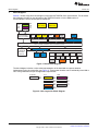
Section 1 shows a high-level block diagram of the superset TMS570LS31x microcontroller. For the actual
block diagram relevant for any derivative of the TMS570LS series or for the RM4x series of
microcontrollers, see the device-specific data sheet.
3M
Flash
with
ECC
64K
ETM-R4
(CPU Trace)
256K
RAM
with
ECC
64K
64K
64K
Dual Cortex-R4F
CPUs in Lockstep
DMA
DMM
POM
Switched Centrol Resource
RTP
(RAM Trace)
FTU
HTU1
HTU2
EMAC
Switched Centrol Resource
Switched Centrol Resource
Main Cross Bar: Arbitration and :Prioritization Control
64 KB Flash
for EEPROM
Emulation
with ECC
CRC
Peripheral Central Resource Bridge
Switched Central Resource
EMAC
EMIF
Slave
MibADC1
MibADC2
N2HET1
I2C
N2HET2
DCAN1
SCI
LIN
FlexRay
DCAN2
MibSPIx
GIO
DCAN3
SPI2
SPI4
Figure 1. Device Block Diagram
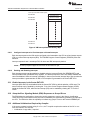
The block diagram includes a color-coded representation of the individual core-power domains
implemented on the microcontroller (see Figure 2). These power domains can be individually turned ON or
OFF during initialization as per the application requirements.
Core/RAM
Core
always on
#1
RAM
#2
#3
#4
#5
#1
#2
#3
Figure 2. Color Legend for Block Diagram
2
Initialization of Hercules™ ARM® Cortex™-R4F Microcontrollers
Copyright © 2013, Texas Instruments Incorporated
SPNA106D – May 2013
Submit Documentation Feedback