1
Standard Initialization Sequence for Hercules Microcontrollers
www.ti.com
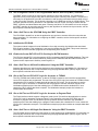
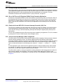
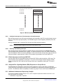
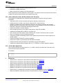
28. Start a self-test on all on-chip dual-port SRAMs using the PBIST controller (Section 2.23).
29. Run the self-test on the CPU's SECDED logic for accesses to main data RAM (B0TCM and B1TCM)
(Section 2.24).
30. Run the self-test on the CPU's SECDED logic for accesses to the main Flash memory (ATCM)
(Section 2.25).
31. Wait for self-test to complete and pass on all on-chip dual-port SRAMs.
32. Start a self-test on all on-chip single-port SRAMs excluding the CPU RAM using the PBIST controller
(Section 2.26).
33. Wait for self-test to complete and pass on all on-chip single-port SRAMs.
34. Start auto-initialization for all other on-chip SRAMs (Section 2.27).
35. Check if the auto-initialization process for all RAMs is completed; wait here if it has not completed.
36. Check the parity error detection mechanism for all peripheral memories (Section 2.28).
37. Enable the CPU’s dedicated vectored interrupt controller (VIC) port (Section 2.29).
38. Program all interrupt service routine addresses in the vectored interrupt manager (VIM) memory
(Section 2.30).
39. Configure IRQ / FIQ interrupt priorities for all interrupt channels (Section 2.30.1).
40. Enable the desired interrupts (IRQ and/or FIQ) inside the CPU (Section 2.31).
41. Enable the desired interrupts in the VIM control registers (Section 2.30.2).
42. Set up the application responses to inputs to the error signaling module (ESM) (Section 2.32).
43. Initialize copy table, global variables, and constructors (Section 2.33).
44. Verify that the dual-clock-comparator (DCC) module can actually detect and flag a frequency error.
45. Configure the DCC module to continuously monitor the PLL output.
46. Verify that a memory protection unit (MPU) violation for all bus masters is flagged as an error to the
ESM.
47. Run a background check on entire Flash using CRC and DMA.
48. Run the offset error calibration routine for the ADC.
49. Run a self-test on the analog-to-digital converter (ADC) analog input channels.
50. Check I/O loop-back for all peripherals.
51. Set up the MPU for the bus masters.
52. Set up the digital windowed watchdog (DWWD) module service window size and the module response
on a violation (reset or NMI).
53. Configure the N2HET1-to-N2HET2 monitoring functionality.
54. Configure desired access permissions for peripherals using the Peripheral Central Resource (PCR)
controller registers.
55. Configure external safety companion, e.g., TI TPS6538x, for online diagnostic operation.
56. Set up the real-time interrupt (RTI) module for generating periodic interrupts as required by the
application.
57. Call the main application (Section 2.35).
4
Initialization of Hercules™ ARM® Cortex™-R4F Microcontrollers
Copyright © 2013, Texas Instruments Incorporated
SPNA106D – May 2013
Submit Documentation Feedback