1
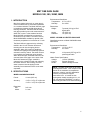
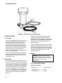
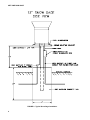
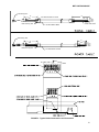
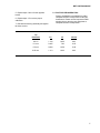
MET ONE RAIN GAGE
MODELS 380, 385, 380M, 385M
REVISION: 2/96
COPYRIGHT (c) 1993-1996 CAMPBELL SCIENTIFIC, INC.
WARRANTY AND ASSISTANCE
The MET ONE RAIN GAGE--MODELS 380, 385, 380M, 385M is warranted by CAMPBELL SCIENTIFIC,
INC. to be free from defects in materials and workmanship under normal use and service for twelve (12)
months from date of shipment unless specified otherwise. Batteries have no warranty. CAMPBELL
SCIENTIFIC, INC.'s obligation under this warranty is limited to repairing or replacing (at CAMPBELL
SCIENTIFIC, INC.'s option) defective products. The customer shall assume all costs of removing,
reinstalling, and shipping defective products to CAMPBELL SCIENTIFIC, INC. CAMPBELL SCIENTIFIC,
INC. will return such products by surface carrier prepaid. This warranty shall not apply to any CAMPBELL
SCIENTIFIC, INC. products which have been subjected to modification, misuse, neglect, accidents of
nature, or shipping damage. This warranty is in lieu of all other warranties, expressed or implied, including
warranties of merchantability or fitness for a particular purpose. CAMPBELL SCIENTIFIC, INC. is not
liable for special, indirect, incidental, or consequential damages.
Products may not be returned without prior authorization. To obtain a Returned Materials Authorization
(RMA), contact CAMPBELL SCIENTIFIC, INC., phone (435) 753-2342. After an applications engineer
determines the nature of the problem, an RMA number will be issued. Please write this number clearly on
the outside of the shipping container. CAMPBELL SCIENTIFIC's shipping address is:
CAMPBELL SCIENTIFIC, INC.
RMA#_____
815 West 1800 North
Logan, Utah 84321-1784
CAMPBELL SCIENTIFIC, INC. does not accept collect calls.
Non-warranty products returned for repair should be accompanied by a purchase order to cover the repair.
815 W. 1800 N.
Logan, UT 84321-1784
USA
Phone (435) 753-2342
FAX (435) 750-9540
www.campbellsci.com
Campbell Scientific Canada Corp.
11564 -149th Street
Edmonton, Alberta T5M 1W7
CANADA
Phone (403) 454-2505
FAX (403) 454-2655
Campbell Scientific Ltd.
Campbell Park
80 Hathern Road
Shepshed, Leics. LE12 9RP
ENGLAND
Phone (44)-50960-1141
FAX (44)-50960-1091
MET ONE RAIN GAGE
MODELS 380, 385, 380M, 385M
1. INTRODUCTION
Met One's tipping bucket rain or snow gage is
used to measure rain or snow water equivalent
on a continuous basis. The Model 380 rain gage
is intended to measure rainfall during above
freezing conditions. The Model 385 AC heated
rain gage provides year round measurement of
either rain or snow. In the standard versions
Model 380/385, precipitation is measured in
increments of 0.01 inches. The metric version,
Model 380M/385M, available by special order,
measures precipitation in increments of 0.1 mm.
The Model 380 rain gage works by collecting
rainfall in the 12 inch collection funnel and
metering the rain into the tipping bucket
assembly. When 0.01 inches of rainfall are
collected, the tipping bucket assembly tips and
activates a mercury switch. The switch closure
is recorded by the datalogger pulse channel.
When the bucket tips, the water drains out the
screened base of the gage. In the case of the
Model 385 heated rain gage, snowfall is
captured in the collection funnel and melted by
the heater element. After melting, the snow
water is metered into the tipping bucket
assembly for measurement of the snow water
equivalent.
2. SPECIFICATIONS
MODEL 380/380M RAIN GAGE
Funnel:
12 inch (30.5 cm)
Accuracy:
±0.5% < 0.5"(1.27 cm)/hr rate
±2.0% < 3.0"(7.62 cm)/hr rate
Resolution:
380:
380M:
Environmental Conditions:
Temperature: 0°C to +50°C
Humidity:
0 to 100%
Dimensions:
Weight:
Height:
Diameter:
7 pounds (3.2 kg) w/ 50 ft.
signal cable
14" (35.5 cm)
12" (30.5 cm)
MODEL 385/385M AC HEATED RAIN GAGE
Specifications same as Model 380/380M unless
listed below.
Environmental Conditions:
Temperature: -20°C to +50°C
Humidity:
0 to 100%
Weight:
12.2 pounds (5.57 kg) w/ 50'
power/signal cable
Heater Power Specification:
Voltage:
115VAC (50/60Hz)
Current:
5 amps maximum
Heater:
300W Cartridge Element
NOTE: The black outer jacket of the cable
®
is Santoprene rubber. This compound was
chosen for its resistance to temperature
extremes, moisture, and UV degradation.
However, this jacket will support
combustion in air. It is rated as slow
burning when tested according to U.L. 94
H.B. and will pass FMVSS302. Local fire
codes may preclude its use inside buildings.
0.01 inch
0.1 mm
1
MET ONE RAIN GAGE
385-SV
(
)
FIGURE 1. 385 Met One Rain and Snow Gage
3. INSTALLATION
3.1 LOCATION
The rain or snow gage should be mounted in a
relatively level spot which is representative of
the surrounding area. The lip of the funnel
should be horizontal and at least 30 inches
above the ground. Install the snow gage high
enough to prevent burial by snow during the
winter months. The ground surface around the
rain gage should be natural vegetation or
gravel. The gage should not be installed over a
paved or concrete surface.
The rain or snow gage should be placed away
from objects that obstruct wind. The minimum
distance should be 2 times the height of the
obstruction or more.
3.2 MOUNTING
The rain or snow gage is designed to mount on
a flat surface. Three equally spaced adjustable
mounting legs are provided. The mounting legs
are pre-drilled for 1/4" bolts on a 9.66" diameter
bolt circle. A mounting bracket is available from
Campbell Scientific (P/N 7792) to install either
the rain or snow gage on a 1-1/4" threaded
pipe. The mounting bracket provides additional
adjustment for leveling the rain or snow gage. A
typical snow gage installation is illustrated in
Figure 2.
2
Loosen the three screws and lift the housing
assembly from the base. Adjust the three
slotted feet on the base of the rain gage and/or
the three nuts on the 380MB to level the gage.
A bubble level is mounted on the base to
facilitate leveling.
Remove the rubber shipping band securing the
stainless steel tipping bucket assembly. Verify
the bucket tips freely and that all the adjusting
screws are tight. Replace the housing assembly
and tighten the three screws to secure the
housing to the base.
3.3 WIRING
WARNING: Disconnect heater power
before attempting to service or repair this
equipment. Failure to do so may result in
personal injury or death due to
electrocution.
3.3.1 DATALOGGER WIRING
CR10, 21X, and CR7:
BLACK(+5V)-------------------Pulse Channel
CLEAR(Ground)--------------GND
WHITE(Shield)----------------GND
MET ONE RAIN GAGE
The BLACK (+5V Signal) lead connects to a
pulse channel. The CLEAR (Power Ground)
connects to any ground channel (G). The
WHITE (shield) lead connects to any ground
channel (G). The purpose of the shield wire is to
drain any charges built up in the cable due to
transients etc.
NOTE: If a pulse channel is not available,
Control Port 7 or 8 can be used to record
switch closures from a rain gage with the
CR10 datalogger. Refer to the CR10
datalogger manual, section 8.5, for
additional information.
3.3.2 HEATER WIRING
Attach the power plug supplied with the Model
385 by following the instructions supplied with
the plug. The electric heated snow gage
requires 115VAC (50/60hz), 5 amps maximum,
to operate the heater. If supplying your own
signal or power cable, refer to Figure 3 for an
illustration of cable installation. The heater
should be unplugged during warmer months to
prevent evaporation during low rainfall and to
minimize wear and tear on the heater element.
NOTE: The heater thermostat is factory set
and requires no field adjustment.
BDR320:
BLACK (+5V)-------------------------P1
CLEAR (Ground)--------------------GND
WHITE (Shield)----------------------GND
NOTE: On BDR320's, only pulse channel 1
can be used to measure a tipping bucket
signal.
3
MET ONE RAIN GAGE
FIGURE 2. Typical Snow Gage Installation
4
MET ONE RAIN GAGE
P/N 2196 (2) Plcs.
6"
Cut Shield Off Flush to Jacket
8"
3/8"
3/8"
CLEAR
CLEAR
SHIELD
BLACK
BLACK
White Heat Shrink
Heat Shrink (2) Plcs.
P/N 2222 Beldon #8641
P/N 2196 (3) Plcs.
2"
3/8"
8"
3/8"
BLACK
WHITE
GREEN
Heat Shrink (2) Plcs.
P/N 7805 Beldon #1934B
FIGURE 3. Typical Cable Construction and Connection
5
MET ONE RAIN GAGE
3.4 DATALOGGER INSTRUCTIONS
CR10, 21X, CR7 Programming:
The Model 380 rain gage is measured using
Instruction 3 configured for a switch closure
(option code 2).
In the following example, the CR10 continuously
measures rainfall and outputs the time, date,
and total rainfall every 60 minutes:
Input Location Labels:
01:
01:
01:
02:
03:
04:
05:
06:
1
60
P3
1
1
2
1
0.01
0
5. CALIBRATION
The sensor is factory calibrated; recalibration is
not required unless damage has occurred or the
adjustment screws have loosened.
Nevertheless, the following calibration check is
recommended once every 12 months:
a. Remove the housing assembly from the
base by loosening the three screws and lifting
upward on the housing.
1. Rain (in)
*
assembly. Verify the tipping bucket assembly
moves freely, and that the datalogger records
0.01 in or 0.1 mm for each bucket tip.
Table Programs
Sec. Execution Interval
Pulse
Rep
Pulse Input Channel
Switch Closure
Loc [:Rain (in)]
Mult
Offset
02:
01:
02:
03:
P92
0
60
10
If time is
minutes into a
minute interval
Set high Flag 0
03:
01:
P77
110
Real Time
Day,Hour-Minute
04:
01:
02:
P72
1
1
Totalize
Repetitions
Starting Input Location
05:
P
End Table 1
b. Check bubble level to verify sensor is
level.
c. Pour water through the inner funnel to wet the
two bucket surfaces. Using a graduated cylinder,
slowly pour the appropriate amount of water
(refer to Table 1) through the inner funnel to the
tipping bucket, which should tip once. Repeat for
the other bucket. If both buckets tip when filled
with the appropriate amount of water (refer to
Table 1), the sensor is properly calibrated and no
additional adjustment is needed. If either bucket
fails to tip, recalibrate as follows:
1. Release the lock nuts on the cup
adjustments.
2. Move the adjustment screws down to a
position that would place the bucket far out of
calibration.
3. Pour the appropriate amount of water (see
Table 1) into the inner funnel (i.e. 18.52 ml for
0.01 inches of rain / tip):
In all dataloggers, a multiplier of 0.01 converts
the output to inches and a multiplier of 0.254
converts the output to millimeters.
Conversion Factors:
Tip to in3:
113.04 in2 (catch orifice area) x
increment in inches.
The metric versions use a multiplier of 0.1 to
convert output to millimeters. A multiplier of
0.00394 converts the output to inches.
in3 to ml:
multiply by 16.3881.
4. MAINTENANCE
During each site visit, check for and remove any
debris, insects, sediment, etc. from the collection
funnel, debris screens, or tipping bucket
6
ml to ounces: multiply by 0.03382.
4. Turn the cup adjustment screw, opposite the
full bucket, up until the bucket assembly tips.
Tighten the lock nut.
MET ONE RAIN GAGE
5. Repeat steps 3 and 4 for the opposite
bucket.
5.1 FACTORY RECALIBRATION:
Factory recalibration is available from either
Campbell Scientific Incorporated or Met One
Instruments. Please call and request an RMA
number prior to returning any equipment to
Campbell Scientific Incorporated
6. Repeat steps 1-5 to ensure proper
calibration.
7. Reinstall the housing assembly and tighten
the three screws.
TABLE 1
Tip
Increment
in3
ml
ounces
0.01 in
1.130
18.52
0.63
0.1 mm
0.445
7.29
0.25
0.2 mm
0.890
14.59
0.49
0.25 mm
1.113
18.23
0.62
7