1
®
EPC -21/22
Hardware Reference
®
RadiSys Corporation
15025 S.W. Koll Parkway
Beaverton OR 97006
Phone: 800-950-0044
In Oregon: (503) 646-1800
______________________________________________________________________
07-0138-02
August 1993
EPC-21/22 Hardware Reference
EPC and RadiSys are registered trademarks of RadiSys Corporation. OS/2, IBM, and
PC/AT are trademarks of International Business Machines Corporation. Microsoft
and MS-DOS are registered trademarks of Microsoft Corporation. Intel386 is a
trademark of Intel Corporation.
August 1992
Copyright © 1992 by RadiSys Corporation
All rights reserved.
Page ii
EPC-21/22 Hardware Reference
Hardware Warranty
RadiSys Corporation ("RadiSys") warrants the EPC system and component modules
to the original purchaser for two years from the product's shipping date. If an EPC
product fails to operate in compliance with its specification during this period,
RadiSys will, at its option, repair or replace the product at no charge. The customer
is, however, responsible for shipping the product; RadiSys assumes no responsibility
for the product until it is received. This warranty does not cover repair of products
that have been damaged by abuse, accident, disaster, misuse, or incorrect installation.
RadiSys' limited warranty covers products only as delivered. User modification, such
as the addition of memory arrays or other devices, may void the warranty, and if the
product is damaged during installation of the modifications, this warranty does not
cover repair or replacement.
This warranty in no way warrants suitability of the product for any specific
application.
IN NO EVENT WILL RADISYS BE LIABLE FOR ANY DAMAGES,
INCLUDING LOST PROFITS, LOST SAVINGS, OR OTHER INCIDENTAL OR
CONSEQUENTIAL DAMAGES ARISING OUT OF THE USE OR INABILITY
TO USE THE PRODUCT EVEN IF RADISYS HAS BEEN ADVISED OF THE
POSSIBILITY OF SUCH DAMAGES, OR FOR ANY CLAIM BY ANY PARTY
OTHER THAN THE PURCHASER.
THE ABOVE WARRANTY IS IN LIEU OF ANY AND ALL OTHER WARRANTIES, EXPRESSED OR IMPLIED OR STATUTORY, INCLUDING THE
WARRANTIES OF MERCHANTABILITY, FITNESS FOR A PARTICULAR
PURPOSE OR USE, TITLE AND NONINFRINGEMENT. Repair or replacement
as provided above shall be the Purchaser's sole and exclusive remedy and RadiSys'
exclusive liability for any breach of warranty.
Page iii
EPC-21/22 Hardware Reference
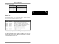
Table of Contents
1. Product Description ............................................................................................... 1
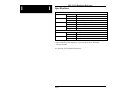
Specifications ....................................................................................................... 2
2. Configuring the BIOS Setup ................................................................................. 3
Power-On Screen Display ....................................................................................
BIOS Setup Screen ..............................................................................................
EXM Setup Screen ...............................................................................................
Fixed Disk Menu .................................................................................................
User-Definable Drive Types ..........................................................................
3
4
6
7
8
3. Theory of Operation .............................................................................................. 11
Processor and Coprocessor ..................................................................................
Memory ................................................................................................................
Figure 1: Base Memory Chip Location ..................................................
Memory Expansion .......................................................................................
Memory Map .................................................................................................
Cache (EPC-22 only) ...........................................................................................
ROM and ROM Shadowing .................................................................................
Battery ..................................................................................................................
Figure 2: Battery Replacement ...............................................................
Video Controllers .................................................................................................
Front Panel LED ..................................................................................................
Resetting the EPC ................................................................................................
EXM Expansion Interface ....................................................................................
Watchdog Timer ..................................................................................................
11
11
11
12
13
14
14
14
15
15
16
16
17
17
4. Connectors ............................................................................................................. 19
Serial Ports ...........................................................................................................
Keyboard ..............................................................................................................
EXM Expansion Connector .................................................................................
EXM Expansion Connector Signals ....................................................................
Page iv
19
20
20
21
EPC-21/22 Hardware Reference
5. Troubleshooting & Error Messages ..................................................................... 27
Troubleshooting ................................................................................................... 27
Common Error Messages ..................................................................................... 28
6. Support and Service .............................................................................................. 35
Appendix A: Mechanical Dimensions ...................................................................... A1
Appendix B: Programming the Watchdog Timer .................................................. A3
Page v
EPC-21/22 Hardware Reference
NOTES
Page vi
1
1. Product Description
The EPC-21 and EPC-22 are PC/AT compatible CPU modules in a very small form
factor (3" x 5.9") based on the Intel386 SL chip set. These EPCs have been designed
to meet stringent safety and low EMI standards (UL-1950). All front panel accessible
ports have filter networks for reduced EMI and increased ESD protection.
Throughout this manual, the term EPC is used to designate both the EPC-21 and the
EPC-22. Where necessary, differences between the EPC-21 and EPC-22 are
specified separately.
Each processor module contains the following:
•
The EPC-21 contains a 16 MHz Intel386 SL processor
•
The EPC-22 contains a 25 MHz Intel386 SL processor and an 80387SX
math coprocessor
•
The EPC-22 contains 64 Kbytes of SRAM cache
•
Up to 20 MBytes of DRAM memory
•
Keyboard interface
•
1 standard 9-pin DTE serial port (COM1)
•
1 RJ-45 serial port (COM2)
•
Time-of-day clock with user replaceable battery
•
Award BIOS
•
Watchdog Timer
•
EXM expansion interface (electrically similar to the 16-bit PC/AT ISA bus)
Page 1
1
EPC-21/22 Hardware Reference
1
1
Specifications
Environmental
Temperature
Humidity
Vibration
Shock
Electrical
EPC-21
EPC-22
operating
storage
operating
storage
operating
storage
operating
storage
0° to 60° C (* see below)
-40° to 125° C
0 - 95% (non-condensing)
0 - 95% (non-condensing)
.015"PP 2.5g (max) 5-2000 Hz
.030"PP
5g (max) 5-2000 Hz
30g 11 msec duration
50g 11 msec duration
maximum
typical
maximum
typical
+5V @ 850 mA
+5V @ 650 mA
+5V @ 1.25 A
+5V @ 1.1 A
* Upper temperature limit degrades 2° C per 1000 ft. elevation. Maximum
elevation 10,000 ft.
See Appendix A for mechanical dimensions.
Page 2
2. Configuring the
BIOS Setup
2
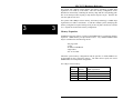
Power-On Screen Display
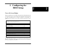
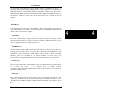
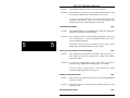
Whenever a hardware reset of the EPC occurs (power-on or front panel reset), the
system performs a power-on self-test (POST) which will display information showing
the status of the BIOS self test if a monitor is attached via a video adapter. If
everything proceeds normally, the screen image will appear approximately as shown
below.
386SL Modular BIOS V3.06abd.
Copyright (c) 1984-90 Award Software Inc.
Copyright 1992 RadiSys Corporation BIOS V3.06
TESTING
TESTING
TESTING
TESTING
INTERRUPT CONTROLLER #1 ......................... OK
INTERRUPT CONTROLLER #2 ......................... OK
CMOS BATTERY .................................... OK
CMOS CHECKSUM ................................... OK
SIZING SYSTEM MEMORY .............................. 640K FOUND
TESTING SYSTEM MEMORY ............................. 640K OK
CHECKING UNEXPECTED INTERRUPTS AND STUCK NMI ............ OK
TESTING PROTECTED MODE .................................. OK
SIZING EXPANSION MEMORY .......................... 3072K FOUND
TESTING MEMORY IN PROTECTED MODE ................. 3712K FOUND
TESTING PROCESSOR EXCEPTION INTERRUPTS .................. OK
TESTING ONBOARD SERIAL PORT #1 .......................... OK
TESTING ONBOARD SERIAL PORT #2 .......................... OK
RadiSys EPC Setup Program
The values shown in the two lines SIZING EXPANSION MEMORY and TESTING
MEMORY IN PROTECTED MODE may be different than shown above depending on
the memory configuration of each system.
Page 3
2
EPC-21/22 Hardware Reference
2
2
If errors occur during the power-on self-test, the BIOS will display the error on the
appropriate line of the screen display and attempt to continue. For instance, if a
failure is discovered in COM1, the BIOS will disable COM1, display the error on the
line "TESTING ONBOARD SERIAL PORT #1 ....." and then continue as if the error
did not occur. It is important to watch the POST display to verify that no errors
occur.
If error messages are displayed during or after the POST display, see chapter 5,
Troubleshooting & Error Messages on page 27.
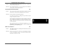
BIOS Setup Screen
The EPC-21/22 BIOS contains a setup function to display and alter the system
configuration. This configuration information is maintained in the EPC's batterybacked CMOS RAM and is used by the BIOS to initialize the EPC's hardware.
The setup function can be invoked any time after the POST completes and first clears
the screen. Simultaneously press the CTRL+ALT+ESC keys. This may be done
during system operation in most, but not all circumstances. Some programs that take
control of the keyboard at a low level, such as Microsoft Windows, cause this key
sequence to be interpreted differently, or not at all. It should always work, however,
when the DOS operating system prompt is shown on the screen.
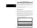
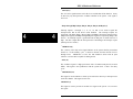
The main setup screen resembles the following:
RadiSys EPC-22 CMOS Setup, BIOS V3.06
386SL, 4 MBytes memory, 387SX present
Date (mm/dd/yy) ............. 08/12/93
Time (hh:mm:ss) ............. 07:34:56
Configuration Errors ........ Halt on all errors
Diskette Drive A
Diskette Drive B
Fixed Disk Drive
Fixed Disk Drive
............ 1.4M 3.5 inch
............ None
C .... AT
D .... None
Com1: ........................ Enabled
Com2: ........................ Enabled
Cache ........................ Enabled
Quick Boot .................. Disabled
Available EXM Slots ......... 8 slots
Page 4
F2
F3
F10
ESC
↑ ↓
← →
=
=
=
=
↵
EXM Menu
Fixed Disk Menu
Save CMOS and EXM data
Exit without saving
move between items
select values
Configuring the BIOS Setup
Use the up and down cursor (arrow) keys to move from field to field. For most
fields, once the cursor is positioned at the field, pressing the left and right cursor
(arrow) keys will scroll through the available choices. Once the screen has been
changed to appear as you desire, press the F10 function key to save the changes in
battery-backed CMOS RAM. Then press the F5 function key to confirm the changes
and reboot, F1 to confirm changes but not reboot or ESC to ignore any changes and
exit.
Each field is explained below.
Date and Time
These values are changed by moving to them and typing in the format shown.
Configuration Errors
This field provides several choices about the situations under which the BIOS should
wait for user input if a configuration error is found. The selections are:
1) Halt on all errors
2) Ignore all errors
3) Ignore keyboard errors (allows operation without a keyboard)
4) Ignore disk errors
5) Ignore keyboard and disk errors
Diskette Drive
This field gives you several choices about the type of floppy disk drives installed as
the A and B drives. Toggle the entry to match the type of diskette drive(s) attached.
If no floppy drive is attached, select NONE for each diskette drive field.
Fixed Disk Drive
This display-only field shows the type of disk selected from the fixed disk menu.
Possible values are None, AT and EXM FLASH. To see the detailed characteristics
of the device or to change the device, use the F3 function key to go to the fixed disk
menu. See the section Fixed Disk Menu, page 7.
Page 5
2
2
EPC-21/22 Hardware Reference
Com1:
Com2:
Toggling these fields enables or disables the Com1 or Com2 ports.
2
2
Cache
This field is valid only on the EPC-22. Toggling this field enables or disables the onboard SRAM cache.
Available EXM Slots
Use the arrow keys to change the displayed number of available EXM slots, or card
cage connectors, in the system's backplane. To determine the correct number of
available EXM slots, count the total number of EXM card edge connectors in the
system's backplane.
As a "worst case" configuration example, if an eight-slot backplane is accidentally set
for only four slots, all EXMs above that fourth slot will not configure. (The only
exception is the video card, which auto-enables to allow for error recovery.)
Continuing with this example, the system would not boot if the boot device was
located above the fourth slot. Information is cleared for the missing four slots, and
must be re-entered once the number of slots is corrected.
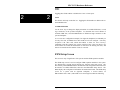
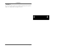
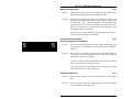
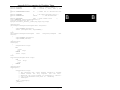
EXM Setup Screen
This screen is only of significance if the system contains EXM expansion modules.
The EXM setup screen is used to configure EXM expansion modules in the system.
It is displayed by pressing the F2 function key from the main setup screen. The
EPC's battery-backed RAM holds the identification and configuration information for
the number of available EXM slots entered in the EXM Main Setup Screen. The
BIOS displays the configuration information in hexadecimal format. The EXM Setup
screen for a system with an eight-slot backplane, a six-slot chassis, an
EMC-FDM in slots 6 and 7, and an EPC-22 in slot 0 might resemble the following:
Page 6
Configuring the BIOS Setup
RadiSys EPC-22 EXM Setup, System BIOS V3.06
386SL, 4 MBytes memory, 387SX present
0
1
2
3
4
5
6
7
FF
ED
7D
DB
D5
DE
7C
FF
00
01
07
C1
C1
00
FF
00
00
00
00
00
00
39
FF
00
F10 = Save and return
ESC = Return without saving
2
↑ ↓ ← → move between items
ID is the unique EXM-ID number.
OB1 and OB2 are option bytes 1 and 2.
The option bytes interpretation is unique to each EXM-ID.
See the EXM user manuals for the semantics of the option bytes.
EXMs must be defined in this screen so the BIOS can correctly identify and initialize
each one at boot-up. Each EXM must be listed by slot number, ID and two option
bytes as defined below.
SLOT
indicates the EXM slot in which the EXM is installed.
ID
is a hard-wired identification value. Each type of EXM has a
unique ID value.
OB1/OB2
are two "option" bytes of configuration information.
All slots not occupied by an EXM module should show an ID of FF indicating that
no EXM is present.
Consult the EXM manual for the correct configuration information for each EXM
expansion module installed.
After all EXMs have been configured, press F10 to save the data or ESC to ignore the
changes. In either case you will be returned to the main setup screen.
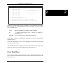
Fixed Disk Menu
The Fixed Disk Menu is used to define the type of hard disk(s) installed in the
system. Enter the Fixed disk menu screen by pressing the F3 function key from the
main setup screen.
Page 7
2
EPC-21/22 Hardware Reference
The Fixed disk menu screen resembles the following:
RadiSys EPC-22 Fixed Disk Menu, System BIOS V3.06
386SL, 4 MBytes memory, 387SX present
2
2
Fixed Disk Drive C:
Type 40
AT
115 MBytes: 814 Cyls,
Landing Zone: 1023
9 Heads, 32 Sectors
Precompensation: None
Fixed Disk Drive D: None
F10 = Save and return
ESC = Return without saving
↑ ↓ ↵ move between items
← → select values
Use the up and down cursor keys (↑ ↓) to move between items. Use the left and right
cursor keys (← → ) to scroll through the available choices for each item.
Disk type AT denotes the many types of non-SCSI PC/AT compatible drives
including IDE. You can scroll through a set of numbered types; the physical
configuration is displayed for each. Scroll through the numeric drive types to find the
one matching the characteristics of the hard drive installed.
Choose disk type EXM Flash if you are using an EXM flash disk. An EXM flash
disk can be made the boot device by making EXM Flash the drive C: type. However,
if Drive C: is EXM Flash, Drive D: must be set to None.
Choose None if there is no hard disk present. This avoids the timeout period used by
the BIOS to conclude that there is no responding device.
User-Definable Drive Types
If the correct AT disk type is not listed, the EPC provides user-editable drive types 48
and 49. Select either of these drive types. Use the TAB key (→| )or the left and right
cursor keys (← →) to move to the next (or previous) field. Note that the default
settings for MBytes, Cylinders, Heads, and Sectors is 1. MBytes is a display-only
field calculated by the BIOS. Move the cursor to each field (Cyls, Heads, and
Sectors) and type the value for that field.
The BIOS allows use of the following maximum values:
Cylinders
Page 8
1023
Heads
63
Sectors
16
Configuring the BIOS Setup
The hard disk you are using may have parameters larger than the allowable
maximum. If the number of cylinders for your drive is greater than the maximum
allowable number, you may have to use 1023 cylinders which will limit the usable
size of the drive. However, most IDE drives support universal translation mode. If
the drive you are using supports this mode and the actual parameters are greater than
the allowable maximum, divide the actual number of cylinders by 2 and multiply the
actual number of heads by 2.
That is, each sector is addressed as an absolute
sequential sector number. Since the drive converts the sector data to an absolute
number, these "false" cylinder and head numbers will still allow the full capacity of
the drive to be used. The example on the next page shows how this is done.
Example:
Cylinders
Heads
Sectors
Total
Sectors
Actual
parameters
1350
5
32
216,000
Conversion
factor
divide by 2
multiply by
2
(none)
Numbers
to Use
675
10
32
216,000
After the fixed disk(s) have been configured, press F10 to save the data or ESC to
ignore the changes. In either case you will be returned to the main setup screen.
Follow the instructions on the screen to save and exit or ignore changes and exit.
Page 9
2
2
EPC-21/22 Hardware Reference
NOTES
2
2
Page 10
3. Theory of Operation
The EPC-21 and EPC-22 are PC/AT compatible processor modules. The standard
functions of the PC architecture are embodied in the Intel386 SL chip set. Unless
otherwise stated, all the following applies to both the EPC-21 and EPC-22.
Processor and Coprocessor
The EPC uses the Intel386 SL CPU.
The EPC-21 runs at 16 MHz without a cache. There is no math coprocessor nor
coprocessor socket.
The EPC-22 runs at 25 MHz with a 64K SRAM cache and includes an Intel 80387SX
math coprocessor. Note that this is not a socketed part.
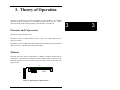
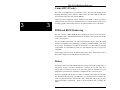
Memory
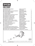
Each EPC has a base memory configuration of 1 MByte or 4 Mbytes soldered on the
motherboard. This memory is arranged as 2 banks (banks 0 and 1) of memory chips
located at locations U12 and U13 on the upper rear corner of the circuit board. See
Figure 1 below.
(Top)
U12
U13
(Rear)
SIMM Socket
Figure 1: Base Memory Chip Location
Page 11
3
3
EPC-21/22 Hardware Reference
For systems with 1 Mbyte of base memory, the memory technology is 4Mbit chips
organized as two 256K by 18-bit banks. This base memory configuration can be
identified on the board by examining the memory chips and the corresponding pads.
The circuit board provides 42 pads per chip but the chips are 40-pin. Therefore the
rear-most pads are not used.
3
3
For systems with 4 MBytes of base memory, the memory technology is 16Mbit chips
organized as two 1MB x 18-bit banks. As with the 1 MByte system, identifying this
memory configuration requires looking closely at the rear pads at location U12 and/or
U13. All pads are used for this memory configuration.
Memory Expansion
In addition to the base memory, a single 72-pin SIMM socket is provided for memory
expansion. SIMM memory occupies banks 2 and 3. Any standard SIMM module
may be used that meets the following criteria:
- fast page mode
- 72-pin
- 80 nanosecond DRAM
- single-sided
- one- or two-bank
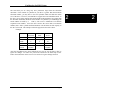
Allowable system memory configurations and the specifics of which SIMM to use
are dependent on the system base memory. The tables below specify the correct
SIMM module for each possible configuration.
For 1 Mbyte of base memory
Total
Memory
1 MB
3 MB
5 MB
9 MB
Page 12
SIMM
Memory
None
2 MB
4 MB
8 MB
SIMM organization
1 bank 1 MB x 18-bit
2 banks 1 MB x 18-bit
1 bank 4 MB x 18-bit
Theory of Operation
For 4 Mbytes of base memory
Total
Memory
4 MB
6 MB
8 MB
12 MB
20 MB
SIMM
Memory
None
2 MB
4 MB
8 MB
16 MB
SIMM organization
1 bank
2 banks
1 bank
2 bank
1 MB x 18-bit
1 MB x 18-bit
4 MB x 18-bit
4 MB x 18-bit
3
Memory Map
The Intel386 SL supports a 25-bit physical memory address. Memory at addresses
between 0 and 20 MB (13FFFFFh) is mapped as follows:
Range
0000000 - 009FFFF
00A0000 - 00BFFFF
Content
DRAM (first 640 KB)
mapped to EXM expansion interface; almost always
used by a video controller as video RAM
00C0000 - 00CFFFF*
Write-protected DRAM containing video BIOS
00D0000 - 00EFFFF*
Uncommitted; mapped to EXM expansion interface
00F0000 - 00FFFFF
Write-protected DRAM containing BIOS
0100000 - 13FFFFF
Extended Memory when installed or
mapped to EXM expansion interface
1400000 - 1FEFFFF
Mapped to EXM expansion interface
1FF0000 - 1FFFFFF
Mapped to BIOS ROM
* 0C8000 - 0EFFFF may be used either as page frame or I/O buffer (i.e. for EMM,
Ethernet, etc.) or may be used by DOS 5.0 as upper memory blocks if an EMM
driver is installed.
Note that since the EXM expansion interface has 24 address lines, some of the
"mapped to EXM expansion interface" address areas map repeatedly, or wrap-around,
in the expansion interface's address space.
Page 13
3
EPC-21/22 Hardware Reference
Cache (EPC-22 only)
The cache is a 64 KB four-way set-associative cache. This is a write-through cache,
meaning that memory writes from the 386SL that hit the cache (find the addressed
location in the cache) also write into the DRAM.
3
3
Addresses from 0 to 640K are cached. Addresses from 640K to 1M are not cached.
Addresses from 1M to the top of installed memory are cached with the exception of a
secondary graphics frame buffer such as is used on the EXM-14 Live video board.
ROM and ROM Shadowing
The EPC contains a BIOS EPROM that is mapped into the top of the processor's
25-bit address space. The EPROM contains the PC BIOS, self test functions, and the
setup screen program.
For best possible performance, the BIOS initialization software copies the ROM
contents into DRAM (called shadowing) at addresses 0F0000-0FFFFF (also called
the "F" page). The BIOS also searches for the existence of a video adapter containing
a video BIOS. If a video BIOS is found, it is copied into the 0Cxxxx ("C" page) area
of DRAM.
After copying into these areas, the BIOS write-protects them. Subsequent writes to
these areas complete successfully but do not alter the data.
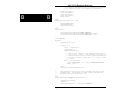
Battery
The battery powers the CMOS RAM and Time of Day clock when system power is
not present. At 60°C, the battery should have a shelf life of over four years. In a
system that is powered on much of the time and where the ambient power-off
temperature is less than 60°C, the battery is estimated to have a life of 10 years.
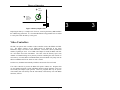
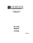
The battery supplied with the EPC is a 23mm. 3V lithium "coin" battery or equivalent
(e.g. Panasonic BR2330 or Rayovac BR2335). It is mounted on the component side
of the circuit board near the bottom front corner. Should the battery fail, you may
obtain and install a replacement. Figure 2 below illustrates how to change the
battery.
Page 14
Theory of Operation
1
2
Gently lift
retaining clip
Slide battery
in/out in line with
the direction of the
retaining clip
(Front
Panel)
(Bottom)
3
Figure 2: Battery Replacement
Replacing the battery is a simple task. However, removing the battery will invalidate
the CMOS setup parameters. It is recommended that all setup parameters be recorded
in a safe place while the battery is still good.
Video Controllers
The EPC can operate with or without a video controller (such as the EXM-6 or EXM13). The BIOS searches for an EXM having an EXM ID in the range
E8h-EFh (a range reserved for video controllers). The search is done by EXM slot
number, beginning at slot 0. If no EXM video adapter is found, the BIOS will look
for a PC add-in card with video BIOS. The CPU scans the memory space from
A0000h to C8000h looking for any memory location containing the value AA55h. If
such memory is found (add-in card BIOS ROM), the main BIOS will "jump" into the
add-in card BIOS and execute whatever code is found.
In either case, the BIOS automatically initializes and uses the first one found.
If no video controller is present, the BIOS will operate without one. Programs that
use the standard operating system and BIOS character output functions can be run
successfully (the output is just ignored). However, programs that rely on specific
video modes, that write directly into the video RAM, or that directly call video BIOS
functions, will fail.
Page 15
3
EPC-21/22 Hardware Reference
Front Panel LED
The EPC has one LED on the front panel. This RUN LED is lit whenever the EPC's
memory is being accessed. It first comes on at power-up and should remain lit as
long as the system is running. It is normal for the RUN LED to flicker during powerup. If the processor halts (or hangs) , the LED will go out.
3
3
Resetting the EPC
There are a number of ways to reset (reboot) the EPC.
Power-off, Power-on
This causes the entire system to reset. The system will run the power-on
self-tests and reboot the operating system.
Front-panel Reset button
The Reset button causes the EPC to perform a hardware reset. The system
will run the power-on self-tests and reboot the operating system.
Expansion Interface
Pin A57 on the EXM expansion connector is defined as ~RESETIN.
Asserting this input (low) will reset the processor. This is provided to allow
remote reset to be implemented. This is a full hardware reset. The system
will run the power-on self-tests and reboot the operating system.
Watchdog Timer
Enabling the watchdog timer and allowing it to expire will reset the
processor. The watchdog timer is tied to ~RESETIN pin described above.
The system will run the power-on self-tests and reboot the operating system.
Setup Screen
Pressing F10 and then F5 to save changes and reboot causes a full hardware
reset.
Page 16
Theory of Operation
CTRL+ALT+DEL
This keyboard sequence is called a "warm boot". The EPC does not
reinitialize all of the processor's hardware. The power-on self-test does not
run. However, the operating system will be reloaded. This type of reset
typically only works under DOS.
Additional abnormal conditions that cause a reset
3
Low Vcc
No DRAM refresh signal from the micromonitor
EXM Expansion Interface
The EXM expansion interface is electrically similar to the PC/AT ISA (16-bit data)
bus. The expansion interface is provided on both sides of the edge connector on the
rear of the EPC. See Chapter 4, Connectors for details of the signals provided.
Watchdog Timer
The EPC-21 & 22 use the secondary 8254 timer in the 82360SL chipset to implement
a watchdog timer function. Counter 2 within the 8254 is/should be programmed to
reset the CPU when half of the timer's initial count has expired.
See Appendix B for details on programming the watchdog timer.
Page 17
3
EPC-21/22 Hardware Reference
NOTES
3
3
Page 18
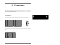
4. Connectors
This chapter specifies the details of the connectors on the EPC. These connectors
adhere to existing standards. Pins are labeled from the point of view of looking into
the front of the connector on the EPC.
Serial Ports
The COM1 serial port is a DB-9 DTE connector defined in the following table.
Pin
1
2
3
4
5
Signal
DCD
RxD
TxD
DTR
Ground
Pin
6
7
8
9
Signal
DSR
RTS
CTS
Ring indicator
5
1
9
6
The COM2 serial port is a DTE RJ-45 phone jack connector defined in the following
table:
RJ-45
1
2
3
4
5
Signal
Shield
CTS
TxD
DTR
RxD
DB25
1
4
3
8
2
Page 19
4
4
1
EPC-4 Hardware Reference
8
6
7
RTS
8
DCD
Ground
20
7
5
Keyboard
The keyboard connector is a 6-pin DIN defined as
4
4
Pin
1
2
3
Signal
Data
not used
Ground
Pin
4
5
6
4
Signal
+5V
Clock
not used
2
6
1
3
5
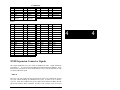
EXM Expansion Connector
The EXM expansion connector on the rear of the EPC is a 116-pin cardedge
connector. The mating connector is an AMP 650090-1 or equivalent. The connector
pin numbers are divided into the A side and the B side. Pins A1 through A58 are on
the component side of the board with pin A1 at the bottom of the board. Pins B1
through B58 are on the solder side of the board with pin B1 at the bottom of the
board. The pin assignments are listed in the tables below followed by signal
definitions.
A Row:
Pin
A1
A2
A3
A4
A5
A6
A7
A8
A9
Signal
(unused)
(reserved)
+5V
+5V
SD15
SD13
SD11
(unused)
SD9
Page 20
Pin
A16
A17
A18
A19
A20
A21
A22
A23
A24
Signal
IRQ12
IRQ11
IRQ7
IRQ5
+5V
(reserved)
-IOCHK
DRQ6
DRQ5
Pin
A31
A32
A33
A34
A35
A36
A37
A38
A39
Signal
-DACK3
-DACK2
(reserved)
-DACK1
-DACK0
-SBHE
+5V
AEN
SA23
Pin
A45
A46
A47
A48
A49
A50
A51
A52
A53
Signal
SA13
(key)
(key)
SA11
SA9
OSC
SA7
SA5
SA3
Connectors
A10
A11
A12
A13
A14
A15
SD7
SD5
(unused)
SD3
SD1
IRQ15
A25
A26
A27
A28
A29
A30
DRQ3
DRQ2
DRQ1
DRQ0
-DACK6
-DACK5
A40
A41
A42
A43
A44
SA21
SA19
SA17
TC
SA15
A54
A55
A56
A57
A58
SA1
+5V
+5V
-RESETIN
(unused)
Pin
B16
B17
B18
B19
B20
B21
B22
B23
B24
B25
B26
B27
B28
B29
B30
Signal
GND
IRQ9
IRQ6
IRQ4
IRQ3
-RSTDRV
GND
IOCHRDY
-0WS
-IOCS16
-MEMCS16
-REFRESH
GND
-IOW
-IOR
Pin
B31
B32
B33
B34
B35
B36
B37
B38
B39
B40
B41
B42
B43
B44
Signal
-SMEMW
-SMEMR
GND
-MEMW
-MEMR
BALE
CLK
GND
SA22
SA20
SA18
SA16
GND
SA14
Pin
B45
B46
B47
B48
B49
B50
B51
B52
B53
B54
B55
B56
B57
B58
Signal
SA12
(key)
(key)
SA10
SA8
GND
SA6
SA4
SA2
SA0
GND
GND
-EXTSMI
GND
B Row:
Pin
B1
B2
B3
B4
B5
B6
B7
B8
B9
B10
B11
B12
B13
B14
B15
Signal
GND
(reserved)
GND
GND
SD14
SD12
SD10
GND
SD8
SD6
SD4
GND
SD2
SD0
IRQ14
EXM Expansion Connector Signals
The signal definitions below are listed in alphabetical order. Signal definitions
preceded by a are copied from the IBM AT Technical Reference Manual. Some
liberties have been taken to correct the definitions for use with the Intel386 SL chip
set and an 8 MHz bus speed.
-0WS (I)
The 'zero wait state' signal tells the microprocessor that it can complete the present
bus cycle without inserting any additional wait cycles. In order to run a memory
cycle to a 16-bit device without wait cycles, 0WS is derived from an address decode
gated with a Read or Write command. In order to run a memory cycle to an 8-bit
Page 21
4
4
EPC-4 Hardware Reference
device with a minimum of two wait states, 0WS should be driven active one clock
cycle after the Read or Write command is active, and gated with the address decode
for the device. Memory Read and Write commands to an 8-bit device are active on
the falling edge of CLK. 0WS is active low and should be driven with an open
collector or tri-state driver capable of sinking 20 mA.
4
4
AEN (O)
The 'address enable' signal is used to de-gate the microprocessor and other devices
from the I/O channel to allow DMA transfers to take place. When this line is active,
the DMA controller has control of the address bus, the data-bus Read command lines
(memory and I/O), and the Write command lines (memory and I/O). This signal is
active high.
BALE (O) (buffered)
The 'buffered address latch enable' signal is provided by the Bus Controller and is
used to latch valid addresses and memory decodes from the microprocessor. It is
available to the I/O channel as an indicator of a valid microprocessor or DMA
address (when used with 'address enable' signal, AEN). Microprocessor addresses
SA0 through SA23 are latched with the falling edge of BALE. BALE is forced high
(active) during DMA cycles.
CLK (O)
This is the 8-MHz system 'clock' signal. It is a synchronous microprocessor cycle
clock with a cycle time of 125 nanoseconds. The clock has a 50% duty cycle. This
signal should be used only for synchronization. It is not intended for uses requiring a
fixed frequency.
-DACK0 through -DACK3, -DACK5, & -DACK6 (O)
-DMA acknowledge signals are used to acknowledge DMA requests. These signals
are active low.
DRQ0 through DRQ3, DRQ5, DRQ6 (I)
The 'DMA request' signals are asynchronous channel requests used by peripheral
devices and a microprocessor to gain DMA service (or control of the system). They
Page 22
Connectors
are prioritized, with DRQ0 having the highest priority and DRQ6 the lowest. A
request is generated by bringing a DRQ line to an active (high) level. A DRQ line is
held high until the corresponding 'DMA acknowledge' (DACK) line goes active.
DRQ0 through DRQ3 perform 8-bit DMA transfers, DRQ5 and DRQ6 perform 16bit transfers. DRQ4 is used on the system board and is not available on the I/O
channel.
-EXTSMI (I)
System management interrupt. Non-maskable. This is the highest priority interrupt
even taking priority over NMI. See the Intel386 SL Programming Reference for
details. This is an active low signal.
-I/OCHK (I)
The 'I/O channel check' signal provides the system board with parity (error)
information about memory or devices on the I/O channel. When this signal is active
(low), it indicates a non-correctable system error.
-I/OCHRDY
(I)
The 'I/O channel ready' signal is pulled low (not ready) by a memory or I/O device to
lengthen I/O or memory cycles. Any slow device using this line should drive it low
immediately upon detecting its valid address and a Read or Write command.
Machine cycles are extended by an integral number of clock cycles (125
nanoseconds). This signal should be held low for no more than 2.5 microseconds.
-I/OCS16 (I)
The 'I/O 16-bit chip select' signal indicates to the system that the present data transfer
is a 16-bit I/O cycle.
It is derived from an address decode.
-I/OCS16 is active low and should be driven with an open collector or tri-state driver
capable of sinking 20 mA.
-IOR (I/O)
The '-I/O read' signal instructs an I/O device to drive its data onto the data bus. This
signal may be driven by the system microprocessor or DMA controller, or by a
microprocessor or DMA controller resident on the I/O channel. This signal is active
low.
Page 23
4
4
EPC-4 Hardware Reference
-IOW (I/O)
The '-I/O write' signal instructs an I/O device to read the data off the data bus. It may
be driven by any microprocessor or DMA controller in the system. This signal is
active low.
4
4
IRQ3 through IRQ7, IRQ9, IRQ11, IRQ12, IRQ14, & IRQ15 (I)
Interrupt requests 3 through 7, 9, 11, 12, 14, and 15 are used to signal the
microprocessor that an I/O device needs attention. The interrupt requests are
prioritized, with IRQ9, IRQ11, IRQ12, IRQ14 and IRQ15 having the highest priority
(IRQ9 is the highest), and IRQ3 through IRQ7 having the lowest priority (IRQ7 is the
lowest). An interrupt request is generated when an IRQ line is raised from low to
high. The line is high until the microprocessor acknowledges the interrupt request
(Interrupt service routine).
-MEMCS16 (I)
The '-memory 16-bit chip select' signal indicates to the system that the present data
transfer is a 16-bit memory cycle. It must be derived from the decode of LA17
through LA23. -MEMCS16 is active low and should be driven with an open
collector or tri-state driver capable of sinking 20 mA.
OSC (O)
The 'oscillator' signal is a high-speed clock with a 70-nanosecond period (14.31818
MHz). This signal is not synchronous with the system clock. It has a 50% duty
cycle.
-REFRESH (I/O)
This signal is used to indicate a refresh cycle and can be driven by a microprocessor
on the I/O channel. This signal is active low.
-RESETIN (I)
This signal is used to provide an external reset signal to the system. It is an active
low signal.
Page 24
Connectors
-RSTDRV (O)
The 'reset drive' signal is used to reset or initialize system logic at power-up time or
during a low voltage condition. This signal is active low.
4
Page 25
4
EPC-4 Hardware Reference
SA0 through SA23 (I/O)
Address signals 0 through 23 are used to address memory and I/O devices within the
system. These 24 address lines, in addition to LA17 through LA23, allow access of
up to 16M of memory. SA0 through SA23 are gated on the system bus when
'buffered address latch enable' signal (BALE) is high and are latched on the falling
edge of BALE. These signals are generated by the microprocessor or DMA
controller. They also may be driven by other microprocessors or DMA controllers
that reside on the I/O channel.
4
4
-SBHE (I/O)
The '-system bus high enable' signal indicates a transfer of data on the upper byte of
the data bus, SD8 through SD15. 16-bit devices use -SBHE to condition data bus
buffers tied to SD8 through SD15. This signal is active low.
SD0 through SD15 (I/O)
These signals provide bus bits 0 through 15 for the microprocessor, memory, and I/O
devices. D0 is the least-significant bit and D15 is the most-significant bit. All 8-bit
devices on the I/O channel should use D0 through D7 for communications to the
microprocessor. The 16-bit devices will use D0 through D15. To support 8-bit
devices, the data on D8 through D15 will be gated to D0 through D7 during 8-bit
transfers to these devices; 16-bit microprocessor transfers to 8-bit devices will be
converted to two 8-bit transfers.
-SMEMR (O) -MEMR (I/O)
These signals instruct the memory devices to drive data onto the data bus.
-SMEMR is active only when the memory decode is within the low 1M of memory
space. -MEMR is active on all memory read cycles. -MEMR may be driven by any
microprocessor or DMA controller in the system. -SMEMR is derived from
-MEMR and the decode of the low 1M of memory. When a microprocessor on the
I/O channel wishes to drive -MEMR, it must have the address lines valid on the bus
for one clock cycle before driving -MEMR active. Both signals are active low.
Page 26
Connectors
-SMEMW (O) -MEMW (I/O)
These signals instruct the memory devices to store the data present on the data bus. SMEMW is active only when the memory decode is within the low 1M of the
memory space. -MEMW is active on all memory write cycles. -MEMW may be
driven by any microprocessor or DMA controller in the system. -SMEMW is derived
from -MEMW and the decode of the low 1M of memory. When a microprocessor on
the I/O channel wishes to drive -MEMW, it must have the address lines valid on the
bus for one clock cycle before driving -MEMW active. Both signals are active low.
TC (O)
The 'terminal count' signal provides a high pulse when the terminal count for any
DMA channel is reached.
Page 27
4
4
5. Troubleshooting &
Error Messages
Troubleshooting
This section deals with problems that you may encounter that do not provide an error
message. If an error message is displayed, see the next section of this chapter,
Common Error Messages.
Symptoms
Possible cause(s)
Solution
System appears to boot
(evidenced by RUN LED
being on, floppy and/or
hard disk being accessed)
but provides no video.
Video adapter not fully
seated.
Remove the video adapter. Reinsert
the video adapter and verify proper
seating of the edge connector.
Monitor or cable problem.
Verify that the cable pins are not
bent and the cable is fully seated in
the video adapter. If necessary, try
the monitor on another system to
verify that the monitor is good.
Video adapter failure.
Replace video adapter.
EPC cannot talk to EXM
expansion interface.
Verify that the EPC is fully seated
in the edge connector.
The system is not getting
power.
Verify that +5V power is good and
that the EPC is fully seated.
Hardware failure.
Replace the EPC.
System fails at power-up will not run power-on selftest.
Page 27
5
5
EPC-21/22 Hardware Reference
Symptoms
Possible cause(s)
Solution
Serial port(s) do not work.
Port is disabled in the
Setup screen.
Press CTRL+ALT+ESC to enter the
Setup screen. Use cursor arrows to
move to the appropriate field and
toggle the entry to enable the port.
Interrupt conflicts.
Another module may be using the
same interrupts as COM1 and/or
COM2. Verify that no other card in
system is using IRQ3 or IRQ4.
Port hardware failure.
Replace the EPC.
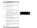
Common Error Messages
5
5
This section contains a summary of error and warning messages alphabetized by
message text. These are messages generated by the BIOS and MS-DOS that may be
related to your hardware configuration.
BAD OR MISSING COMMAND INTERPRETER
Problem:
DOS
The DOS operating system cannot find the Command line interpreter.
Solution(s): Either COMMAND.COM is not present at the specified (or default)
directory level of the boot disk or the "SHELL=" statement in your
CONFIG.SYS lists the file incorrectly (wrong directory or
misspelled).
CMOS CHECKSUM INVALID
Problem:
BIOS
Something in the CMOS RAM is incorrect.
Solution(s): Run the BIOS setup program to determine what is wrong, and correct
it. If the error occurs repeatedly, the EPC's battery has failed.
Page 28
Troubleshooting & Error Messages
CMOS RAM ERROR, CHECK BATTERY / RUN SETUP
Problem:
BIOS
Something in the CMOS RAM is incorrect.
Solution(s): Run the BIOS setup program to determine what is wrong, and correct
it. If the error occurs repeatedly, the EPC's battery has failed.
DISK BOOT FAILURE, INSERT SYSTEM DISK AND PRESS ENTER
Problem:
BIOS
No boot disk could be found.
Solution(s): This could occur in several different ways.
Your hard disk may not have been partitioned into logical drive(s).
PCs look for logical drives to boot from. Hard disks are physical
drives; partitions are logical drives.
If your BIOS setup screen has all disks disabled, or if your hard disk
is disabled and no floppy diskette is inserted in the A: drive. Run the
BIOS setup program and verify that all disk parameters are correct. If
they are, insert a bootable floppy disk in the A: drive and press enter.
If a hard disk is present, verify that it is properly partitioned and
formatted as a system disk and one partition is set active.
DISKETTE DRIVES OR TYPES MISMATCH ERROR - RUN SETUP
Problem:
BIOS
The floppy diskette(s) installed in the system do not match the
configuration information listed in the BIOS setup screen. This may
be due to incorrect entries in the BIOS setup screen or one or both
drives may not be responding at power-up.
Solution(s): Press CTRL+ALT+ESC to run the BIOS setup program. Make sure
the BIOS setup entries relating to floppy drives correctly reflect the
attached floppy drives. If you have no floppy drives, both drive A
and drive B should be set to none.
Also, verify that all floppy drives are firmly connected (via ribbon
cable) and that each drive has power. If the floppy drive is getting
power through the ribbon cable, make sure that the appropriate
jumpers are set correctly.
ERROR INITIALIZING HARD DISK 0
BIOS
Page 29
5
5
EPC-21/22 Hardware Reference
Problem:
The IDE disk controller for drive C cannot be initialized.
Solution(s): Ensure that the +5V power to the controller and hard disk are good
and, if used, the ribbon cable to the hard disk is fully seated.
If you are not using an IDE drive, press CTRL+ALT+ESC to enter
the BIOS setup program. Press F3 to enter the Fixed disk menu.
Change the drive type to match the device being used.
EXM CONFIGURATION ERROR
Problem:
BIOS
The EXMs installed (or not installed) do not match the configuration
information in the BIOS setup EXM menu.
Solution(s): Press CTRL+ALT+ESC to run the BIOS setup program. Press F2 to
enter the EXM menu. Verify the information listed on the screen,
save any changes and reboot.
5
5
If necessary, refer to the section EXM Setup Screen, page 6 of this
manual and/or your EXM manual(s) for more details.
FLOPPY DISK CNTRLR ERROR OR NO CNTRLR PRESENT
Problem:
BIOS
The configuration information in the BIOS setup says that one or
more floppy disk drives are expected, but a floppy disk controller
could not be found.
Solution(s): If you have no floppy diskette drives, press CTRL+ALT+ESC to
enter the setup program and set both floppy drives to "NONE."
If you are using a floppy drive(s), verify that both the floppy
controller and the floppy drive(s) have power.
GENERAL FAILURE READING DRIVE ...
Problem:
DOS
This almost always indicates the presence of an unformatted hard disk
partition or diskette.
Solution(s): Format the partition or diskette using the utilities supplies by your
operating system.
INVALID DRIVE SPECIFICATION
Page 30
DOS
Troubleshooting & Error Messages
Problem:
You are trying to access a logical drive (e.g., A:, B:, ...) that is not
known to the operating system.
Solution(s): Select a different logical drive. If you are trying to access a hard disk,
you may need to create the logical partition.
KEYBOARD ERROR OR NO KEYBOARD PRESENT
Problem:
BIOS
This message indicates that the system did not recognize a keyboard
at power-up or you pressed a key during the power-on self test.
Solution(s): Check the integrity of the keyboard connector.
If you think you pressed a key during power-up, reboot the system
using the front panel reset button.
Some keyboards are designed with a switch (or jumper) to allow the
user to configure the keyboard for use with an AT machine or an XT
machine. If this is the case with your keyboard, verify that the switch
is in the AT position.
The keyboard may not be a valid PC/AT keyboard (e.g., it is a
PC/XT-only or PS/2 keyboard). If this is the case, replace the
keyboard with a PC/AT style keyboard.
MEMORY PARITY INTERRUPT AT ...
Problem:
BIOS
This could be a software error (reading a nonexistent memory area) or
a true hardware failure.
Solution(s): Attempt to repeat the error. If the error occurs during the execution
of your own proprietary software, verify that the memory location
specified in your software is valid.
Page 31
5
5
EPC-21/22 Hardware Reference
MISSING OPERATING SYSTEM
Problem:
BIOS
Although the system could read the hard disk and find the active
partition, the operating system files could not be found.
Solution(s): This can be caused by using a drive type number in the BIOS setup
Fixed Disk menu that does not match the type number used to format
the hard disk. Press CTRL+ALT+ESC to run the BIOS setup
program. Press F3 to enter the Fixed Disk menu. Select the correct
drive type to match the type used to format the disk originally. Save
the changes and reboot the system.
This can also occur if the hard disk is partitioned and one partition is
set active, but the partition is not formatted.
NON-SYSTEM DISK OR DISK ERROR
REPLACE AND PRESS ANY KEY WHEN READY
5
5
Problem:
BIOS
This is caused by an attempt to boot from a disk or diskette that is not
recognized as a system disk; that is no system files exist on the disk or
diskette.
Solution(s): Most often it results when you reboot with a non-system diskette in
the floppy drive, because the BIOS always attempts to boot from the
floppy drive if a diskette is installed.
If you are trying to boot from the hard disk, make sure that you do not
have a diskette in drive A and press any key.
If you are trying to boot from floppy, insert a known good bootable
system diskette in drive A and press any key.
NOT READY READING DRIVE ...
Problem:
DOS
This is usually caused by not fully inserting a diskette into the floppy
drive.
Solution(s): Eject the floppy diskette and reinsert making sure that the diskette
seats completely into the floppy drive.
Page 32
Troubleshooting & Error Messages
PARITY ERROR IN SEGMENT ...
Problem:
DOS
This could be a software error (reading a nonexistent memory area) or
a true hardware failure.
Solution(s): Attempt to repeat the error. If the error occurs during the execution
of your own proprietary software, verify that the memory location
specified in your software is valid.
PRESS A KEY TO REBOOT
Problem:
BIOS
A C: drive partition exists but is not set active.
Solution(s): Run your operating system disk partitioning program (like FDISK)
and set the primary partition active.
REAL TIME CLOCK ERROR - RUN SETUP
Problem:
BIOS
The battery-backed TOD clock is incorrect.
Solution(s): Run the BIOS setup program to determine what is wrong, and correct
it. If the error occurs repeatedly, the EPC's battery has failed.
You should attempt to solve the problem yourself. If you are unable to solve the
problem, please call RadiSys Technical Support.
Page 33
5
5
EPC-21/22 Hardware Reference
NOTES
5
5
Page 34
6. Support and Service
In North America
Technical Support
RadiSys maintains a technical support phone line at (503)
646-1800 that is staffed weekdays (except holidays)
between 8 AM and 5 PM Pacific time.
If you have a
problem outside these hours, you can leave a message on
voice-mail using the same phone number.
You can also
request help via electronic mail or by FAX addressed to
RadiSys Technical Support.
The RadiSys FAX number is
(503) 646-1850.
The RadiSys E-mail address on Internet
is
[email protected].
If
you
are
sending
E-mail or a FAX, please include information on both the
hardware
and
software
being
used
and
a
detailed
description of the problem, specifically how the problem
can be reproduced.
We will respond by E-mail, phone or
FAX by the next business day.
Technical Support Services are designed for customers who
have purchased their products from RadiSys or a sales
representative.
If your RadiSys product is part of a
piece of
OEM equipment, or was integrated by someone
else as part of a system, support will be better provided
by the OEM or system vendor that did the integration and
understands the final product and environment.
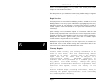
Bulletin Board
RadiSys operates an electronic bulletin board (BBS) 24 hours per day to provide
access to the latest drivers, software updates and other information. The bulletin
Page 35
6
6
EPC-21/22 Hardware Reference
board is not monitored regularly, so if you need a fast response please use the
telephone or FAX numbers listed above.
The BBS operates at up to 14400 baud. Connect using standard settings of eight data
bits, no parity, and one stop bit (8, N, 1). The telephone number is (503) 646-8290.
Repair Services
Factory Repair Service is provided for all RadiSys products. Standard service for all
RadiSys products covers factory repair with customers paying shipping to the factory
and RadiSys paying for return shipment. Overnight return shipment is available at
customer expense. Normal turn-around time for repair and re-certification is five
working days.
Quick Exchange services (immediate shipment of a loaner unit while the failed
product is being repaired) or other extra-cost services can be arranged, but need to be
negotiated in advance to allow RadiSys to pool the correct product configurations.
RadiSys does not maintain a general "loaner" pool: units are available only for
customers that have negotiated this service in advance.
6
6
RadiSys does not provide a fixed-price "swap-out" repair service, as customers have
indicated that issues of serial number tracking and version control make it more
convenient to receive their original products back after repair.
Warranty Repairs
Products under warranty (see warranty information in the
front of this manual) will have manufacturing defects
repaired at no charge.
Products sent in for warranty
repair that have no faults will be subject to a
recertification
charge.
Extended
Warranties
are
available and can be purchased at a standard price for
any product
still under warranty.
RadiSys will gladly
quote prices for Extended Warranties on products whose
warranties have lapsed; contact the factory if this
applies.
Customer induced damage (resulting from misuse, abuse, or
exceeding the product specifications) is not covered by
the standard product warranty.
Page 36
Support and Service
Non-Warranty Services
There are several classes of non-warranty service. These
include repair of customer induced problems, repairs of
failures for products outside the warranty period,
recertification (functional testing) of a product either
in or out of warranty, and procurement of spare parts.
6
Page 37
6
EPC-21/22 Hardware Reference
All non-warranty repairs are subject to service charges.
RadiSys has determined that pricing repairs based on time
and materials is more cost-effective for the customer
than a flat-rate repair charge.
When product is
received, it will be analyzed and, if appropriate, a cost
estimate will be communicated to the customer for
authorization.
After the customer authorizes the repair
and billing arrangements have been made, the product will
be repaired and returned to the customer.
A recertification service is provided for products either
in or out of warranty. This service will verify correct
operation of a product by inspection and testing of the
product with standard manufacturing tests.
There is a
product-dependent charge for recertification.
6
6
There are only a few components that are generally
considered
field-repairable,
but,
because
RadiSys
understands that some customers want or need the option
of repairing their own equipment, all components are
available in a spares program.
There is a minimum
billing charge associated with this program.
Arranging Service
To schedule service for a product, please call RadiSys
Technical Support directly at (503) 646-1800.
Have the
product model and serial numbers available, along with a
description of the problem.
A Technical Support
representative
will
issue
a
Returned
Materials
Authorization (RMA) number, a code number by which we
track the product while it is being processed.
Once you
have received the RMA number, follow the instructions of
the Technical Support representative and return the
product to us, freight prepaid, with the RMA number
clearly marked on the exterior of the package.
If
possible re-use the original shipping containers and
packaging.
In any case, be sure you follow good ESDcontrol practices when handling the product, and ensure
that anti-static bags and packing materials with adequate
padding and shock-absorbing properties are used.
Page 38
Support and Service
Ship the product, freight prepaid, to
Product Service Center
RadiSys Corporation
15025 SW Koll Parkway
Beaverton, Oregon
97006-6902
6
Page 39
6
EPC-21/22 Hardware Reference
When
shipping
the
product,
include
the
following
information:
return address, contact names and phone
numbers in purchasing and engineering, and a description
of the suspected problem. Any ancillary information that
might be helpful with the debugging process will be
appreciated.
Other Countries
Contact the sales organization from which you purchased your RadiSys product for
service and support.
6
6
Page 40
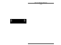
2.96
3.00
0.65
0.0
0.04
.075
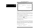
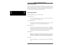
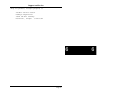
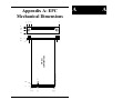
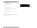
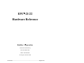
Note: Pins B1 - B58 are on the reverse side
Pin A1
Pin A58
0.325
EPC-21/22
COMPONENT SIDE
0.0
4.14
0.57
0.29
Appendix A: EPC
Mechanical Dimensions
0.0
0.188
0.39
0.78
5.90
5.85
0.0
Page A1
A
A
EPC-21/22 Hardware Reference
A
A
NOTES
Page A2
Appendix B: Programming
the Watchdog Timer
Programming the timer requires entry into the 82360SL configuration space. This
configuration space is enabled by performing four sequential reads to the following
I/O addresses : 0FC23H, 0F023h, 0C023h and 0023h. When enabled access to the
registers within is controlled by two 8-bit read/write registers: the Configuration
Index Register, CFGINDEX (24h) and the Configuration Data Register, CFGDATA
(25h). The CFGINDEX register stores the index of the register to be accessed and
the CFGDATA register stores the data.
The code segment below is a Microsoft C for DOS example of how to enable the
82360SL configuration space:
unsigned short
saveflags()
{
unsigned short flags;
ASM
pushf
pop
flags
ENDASM
return flags;
}
unsigned short
enablespace()
{
unsigned short flags;
flags = saveflags();
_disable();
(void) inp(0xFC23);
(void) inp(0xF023);
(void) inp(0xC023);
(void) inp(0x0023);
return flags;
}
Page A3
B
B
EPC-21/22 Hardware Reference
B
B
The 82360SL configuration space is disabled by setting the Lock bit (bit 0) of the
Configuration Lock Register. Calling the disablespace function below with the
processor flags value returned from the enablespace function disables the
configuration space and restores the system flags to the state prior to the call of
enablespace.
void
restoreflags(unsigned short flags)
{
ASM
push flags
popf
ENDASM
}
void
disablespace(unsigned short flags)
{
outp(CFGINDEX,0xfa);
outp(CFGDATA,0x01);
restoreflags(flags);
}
Once the 82360SL configuration space is visible, the reset enable, timer command
and timeout value can be programmed. The reset enable is active when bit 0 of the
SMOUTCNTRL (index 0xFE) register is cleared (0). Clearing this bit will cause a
PC reset when half of the timer count programmed into the T2CH2CNT has expired.
The watchdog timer's maximum timeout is 491 milliseconds. This is derived by
multiplying the maximum tick count 65535 (0xFFFF) by the clock frequency (15
microseconds), and then dividing by 2 since the PC is reset when half of the count
has expired.
Using the watchdog timer function requires the installation of a driver that
reprograms the watchdog timer value before half the initial timeout count expires.
This is typically done by chaining the PC timer interrupt and reprogramming the
watchdog timer count within the timeout period.
Listed below is a complete program that implements a watchdog timer function.
The watchdog timer is programmed to reset the PC at 491 milliseconds.
#include <dos.h>
#define ASM
#define ENDASM
#define INTERRUPT
#define CFGINDEX
#define CFGDATA
address */
#define T2COMMAND
Page A4
_asm {
}
_interrupt
0x24 /* configuration space index */
0x25 /*
configuration
space
data
0x83 /* timer 2 command address */
Appendix B: Programming the Watchdog Timer
#define T2CH2CNT
0x82 /* timer 2 counter address */
#define TIMER2CW
0xb6 /* counter 2, write, mode 3, bin
*/
#define TIMERTICKRESOLUTION
15
/* Timer has 15 microsecond tick
*/
#define TIMERINT
8
/* PC timer interrupt vector */
#define TIMER2TICKS
0xffff
/* ~491 milliseconds
*/
#define SMOUTCTRL
0xfe /* reset enable latch
*/
void (INTERRUPT *previoustimerfunction)();
volatile unsigned long Tick = 0;
#pragma intrinsic(_disable,_enable,inp,inpw,outp,outpw)
unsigned char
getconfigurationregister(unsigned short slregister)
{
outp(CFGINDEX,slregister);
return ((unsigned char) inp(CFGDATA));
}
void
setconfigurationregister(unsigned
short
slregister,unsigned
slvalue)
{
outp(CFGINDEX,slregister);
outp(CFGDATA,slvalue);
}
unsigned short
saveflags()
{
unsigned short flags;
char
ASM
pushf
pop
flags
ENDASM
return flags;
}
void
restoreflags(unsigned short flags)
{
ASM
push
flags
popf
ENDASM
}
unsigned short
enablespace()
{
unsigned short flags;
/*
// Any interrupt that occurs between saveflags & disable
// should restore the flag register (via the iret).
// Therefore, the flags variable is guaranteed to contain a
// copy of the machines state prior to
disabling
// interrupts.
*/
flags = saveflags();
_disable();
/*
Page A5
B
B
EPC-21/22 Hardware Reference
B
B
//
//
*/
(void)
(void)
(void)
(void)
return
The 82360SL configuration space is enabled by performing
four sequential reads to the addresses listed below.
inp(0xFC23);
inp(0xF023);
inp(0xC023);
inp(0x0023);
flags;
}
void
disablespace(unsigned short flags)
{
outp(CFGINDEX,0xFA);
outp(CFGDATA,0x01);
restoreflags(flags);
}
void
refreshtimer()
{
setconfigurationregister(T2COMMAND,TIMER2CW);
setconfigurationregister(T2CH2CNT,TIMER2TICKS & 0xFF);
setconfigurationregister(T2CH2CNT,TIMER2TICKS >> 8);
}
void INTERRUPT
mytimer()
{
unsigned short flags;
if (Tick == 0)
{
flags = enablespace();
refreshtimer();
disablespace(flags);
/*
// The PC timer executes at 54 millisecond intervals or
// 18.2 times a second.
The Watchdog timer must be
// refreshed within half the timeout period specified in
// the count register [(65535ticks / 2) * 15us / 1000ms
// = 491ms]
*/
Tick = (unsigned short)
((long) TIMER2TICKS / 2L * (long) TIMERTICKRESOLUTION /
1000L / 54L) - 1;
}
Tick--;
_chain_intr(previoustimerfunction);
}
/*
//
This procedure chains the DOS timer interrupt and turns on the
//
watchdog timer. The chained DOS timer handler reprograms the
//
watchdog timer with the initial count.
*/
void
installtimer(void (INTERRUPT *newfunction)())
{
unsigned short flags;
_disable();
previoustimerfunction = _dos_getvect(TIMERINT);
Page A6
Appendix B: Programming the Watchdog Timer
flags = enablespace();
refreshtimer();
setconfigurationregister(SMOUTCTRL,
(unsigned char)(getconfigurationregister(SMOUTCTRL) &
(unsigned char)~1));
disablespace(flags);
_dos_setvect(TIMERINT,newfunction);
_enable();
}
void
deinstalltimer()
{
unsigned short flags;
flags = enablespace();
setconfigurationregister(SMOUTCTRL,
(unsigned char) (getconfigurationregister(SMOUTCTRL) | 1));
_dos_setvect(TIMERINT,previoustimerfunction);
disablespace(flags);
}
main(int argc, char **argv)
{
unsigned short flags;
installtimer(mytimer);
/*
//
Application code goes here ...
*/
deinstalltimer();
}
For more details see the Intel 8254 specification and the Intel 386 SL Microprocessor
Superset Programmer's Reference Manual.
Page A7
B
B
EPC-21/22 Hardware Reference
NOTES
B
B
Page A8