1
MITSUBISHI ELECTRIC
GOT 1000
Graphic Operation Terminal
Training Manual
Basic Course
for GT Designer2
Version2
Art. no:
SH(NA)-080632ENG
01032006
Version A
MITSUBISHI ELECTRIC
INDUSTRIAL AUTOMATION
Safety Precautions
(Make sure to read before training)
When designing a system, always read the relevant manuals and give due consideration to safety.
In addition, pay careful attention to the following points for proper handling during training.
[Precautions during training]
Danger
To prevent electric shock, do not touch the terminal block while the power is supplied.
When opening the safety cover, turn off the power, or make sure that it is sufficiently safe.
Caution
Follow the instructor's directions during training.
Do not remove training machine units or change wiring without permission.
Doing so could cause a breakdown, faulty operation, injury, or fire.
Turn the power OFF before mounting or removing a unit.
Doing so while the current is ON could cause a breakdown or electric shock.
If the training machine emits a strange odour or sound, press the "Power Switch" or the "Emergency
Switch" to stop the machine.
If any trouble occurs, contact the instructor right away.
Revision History
* The textbook number is indicated on the back cover in the lower left corner.
Print date
* Textbook number
Mar, 2006
SH(NA)-080632ENG-A
Revision details
First edition printing
This textbook does not grant any guarantee or license for the use of the industrial property rights or other rights.Mitsubishi
Electric Corporation bears no responsibility for any problems involving property rights which may occur as a result of using
the information in this textbook.
© 2006 MITSUBISHI ELECTRIC CORPORATION
Introduction
About the manuals·········································································································································(5)
System configuration in this text····················································································································(7)
Chapter 1 What is the GOT?
1- 1 to 1-12
1.1 About the GOT ·········································································································································· 1- 1
1.2 Procedures for monitoring the PLC CPU by GOT···················································································· 1- 1
1.3 GOT features············································································································································· 1- 2
1.4 GOT function list········································································································································ 1- 4
1.5 Applicable connection type between the GOT and the PLC CPU ··························································· 1- 6
1.6 Equipments required for using GOT ········································································································· 1- 9
Chapter 2 About GOT Operation
2- 1 to 2-10
2.1 Summary of operation······························································································································· 2- 1
2.2 Entering numerals into PLC ······················································································································ 2- 3
2.2.1 Numerical input function····················································································································· 2- 3
2.2.2 How to operate numerical input ········································································································· 2- 4
2.3 Switching the screen displayed················································································································· 2- 5
2.3.1 The screen type·································································································································· 2- 5
2.3.2 Screen switching device····················································································································· 2- 6
2.3.3 Base screen switching with the sequence program ·········································································· 2- 7
2.3.4 Base screen switching with the touch switch ····················································································· 2- 8
2.3.5 Window screen display and switching ······························································································· 2- 9
Chapter 3 About GT Designer2
3- 1 to 3- 6
3.1 About GT Designer2·································································································································· 3- 1
3.2 GT Designer 2 screen configuration and features···················································································· 3- 1
3.3 How to use the online manual··················································································································· 3- 4
3.3.1 Reading the online manual from the product CD-ROM ···································································· 3- 4
3.3.2 Reading the online manual with the GT Designer2 Help ·································································· 3- 6
Chapter 4 From GOT Screen Creation to the Test
4- 1 to 4-30
4.1 Procedures up to using GOT ···················································································································· 4- 1
4.2 Screen creation ········································································································································· 4- 2
4.2.1 Project creation··································································································································· 4- 2
4.2.2 Communication settings····················································································································· 4- 7
4.2.3 Screen switching device settings ······································································································ 4-10
4.2.4 Data reading ······································································································································ 4-13
4.2.5 Saving the project data······················································································································ 4-15
4.3 Data transfer (PC to GOT) ······················································································································· 4-16
(1)
4.3.1 Connection from PC to GOT············································································································· 4-16
4.3.2 About data types transferred to the GOT·························································································· 4-17
4.3.3 Communication settings···················································································································· 4-18
4.3.4 OS installation···································································································································· 4-19
4.3.5 Screen data download······················································································································· 4-21
4.4 Connection to PLC CPU (bus connection) ······························································································ 4-23
4.4.1 Bus connection unit mounting ··········································································································· 4-23
4.4.2 Connecting the cable························································································································· 4-24
4.5 Checking that GOT is communicating normally with the PLC ································································ 4-25
4.5.1 Checking the OS ······························································································································· 4-25
4.5.2 Checking that the GOT recognizes the connected equipment ························································ 4-26
4.5.3 System alarm····································································································································· 4-28
4.6 Executing the monitor······························································································································· 4-29
Chapter 5 Drawing Fundamentals
5- 1 to 5-56
5.1 Before creating the screen ························································································································ 5- 2
5.1.1 Operations before creating the screen······························································································· 5- 2
5.1.2 Figure drawing ···································································································································· 5- 3
5.2 Text settings ············································································································································· 5-18
5.3 Numerical input/numerical display settings······························································································ 5-20
5.3.1 Numerical input settings···················································································································· 5-20
5.3.2 Numerical display settings················································································································· 5-24
5.4 Lamp display settings ······························································································································· 5-25
5.5 Touch switch settings ······························································································································· 5-27
5.5.1 Bit switch settings······························································································································ 5-27
5.6 Operation check 1 ···································································································································· 5-33
5.7 Comment display settings ························································································································ 5-35
5.7.1 About the comment display··············································································································· 5-35
5.7.2 Comment display settings by bit device···························································································· 5-37
5.8 Window screen creation··························································································································· 5-40
5.9 System alarm settings ······························································································································ 5-44
5.9.1 System alarm settings······················································································································· 5-44
5.9.2 Go to screen switch settings ············································································································· 5-49
5.10 Operation check 2 ·································································································································· 5-52
5.11 Training device list and sequence program··························································································· 5-55
5.12 Method for checking devices using the created screen data································································ 5-56
Chapter 6 About Debug
6- 1 to 6-26
6.1 Extended Function and Option OS ··········································································································· 6- 1
6.2 Training screen creation···························································································································· 6- 3
6.2.1 Screen creation training······················································································································ 6- 3
6.2.2 Project download ································································································································ 6- 5
6.2.3 Training device list and sequence program ······················································································· 6- 6
(2)
6.3 Ladder monitor function····························································································································· 6- 7
6.3.1 About the ladder monitor function ······································································································ 6- 7
6.3.2 Operation check (1)···························································································································· 6- 9
6.3.3 Method for starting the ladder monitor function ················································································ 6-10
6.3.4 Method for factor search operation ··································································································· 6-14
6.3.5 Training screen modification ············································································································· 6-16
6.3.6 Operation check (2)··························································································································· 6-16
6.4 System monitor function··························································································································· 6-17
6.4.1 About the system monitor function···································································································· 6-17
6.4.2 Method for starting the system monitor····························································································· 6-18
6.4.3 Operation check (device monitor operation)····················································································· 6-20
Appendices
Appendix 1 to Appendix 42
Appendix 1 Alarm history display function ·························································································· Appendix 1
Appendix 1.1 About the alarm ········································································································· Appendix 1
Appendix 1.2 About the alarm history display function ··································································· Appendix 3
Appendix 1.3 Settings screen example··························································································· Appendix 7
Appendix 1.4 Alarm history display function settings······································································ Appendix 8
Appendix 1.5 Alarm history display function switch settings························································· Appendix 10
Appendix 1.6 Detail display window screen creation ···································································· Appendix 14
Appendix 1.7 Operation check ······································································································ Appendix 16
Appendix 2 Data transfer to GOT by memory card ·········································································· Appendix 17
Appendix 2.1 Overall procedure···································································································· Appendix 17
Appendix 3 About the FA transparent function ················································································· Appendix 19
Appendix 3.1 System configuration······························································································· Appendix 19
Appendix 3.2 Procedures up to accessing···················································································· Appendix 20
Appendix 3.3 About the restrictions······························································································· Appendix 24
Appendix 4 About Boot OS installation ····························································································· Appendix 26
Appendix 5 Screen data upload ········································································································ Appendix 28
Appendix 6 Glossary ························································································································· Appendix 30
(3)
Introduction
This textbook is a "basic edition".
Practice how to use Mitsubishi Graphic Operation Terminal exercising the training
in this textbook.
[Basic edition]
Learn basic subjects relating to Mitsubishi graphic operation terminal skills.
Course content:
1. GOT1000 series function, performance and system
configuration
2. GOT basic operation and setup procedures
3. Figure and basic object function
(Text, numerical display, numerical input, lamp display,
comment display, touch switch, etc.)
4. Ladder monitor and system monitor function
[Practice edition]
Learn efficient methods to create control screens using Mitsubishi Graphic
Operation Terminal.
Course content:
1. GOT operation and GT Designer2 basic operation
2. How to use advanced object functions
(Layer, graph, comment display, language switching, original
library, parts movement, alarm function)
(4)
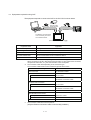
About the manuals
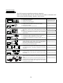
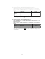
Manual Selection
The GOT manuals are classified according to objectives.
Refer to the following table and then read the manuals suited to understand GOT
main unit and software handling, operation, and functions.
Objective
Reference
● Using GOT for the first time
● Learning about the GOT
● drawing by using GT Designer2
GOT1000
series
The relevant manual (1)
● Learning GT Designer2 screen configuration, how to customize
the screens, and how to from create project data up to transfer
data
The relevant manual (1)
● Learning the specifications and settings of each GT Designer2
object function
The relevant manual (2)
Confirming the applicable connection types for GOT
Confirming the system configuration for each connection type
Confirming the setting method for the unit to be used
Confirming the wiring diagram of connection cable for the unit to
be used
● Confirming the GOT specifications, system configuration,
system equipment, parts names, setup and wiring method,
maintenance and inspection method; error code specifications,
part names, system equipment, and setup method
● Mounting each type of unit on the GOT
Ethernet
relevant manual (1)
● Installing each GOT software in the personal computer
● Running each software
● Learning how to use the online manual
●
●
●
●
GOT1000 series
This textbook and the
The relevant manual (3)
The relevant manual (4)
● Converting the monitor screen data created with GOT900 series
and Digital Electronics Corporation’s package into GOT1000
series data
The relevant manual (5)
● Using the function of GOT main unit and using the GOT debug
to check the status of the target CPU, special function module,
and network
The relevant manual (6)
● By Using a personal computer, reading and writing the data
stored on the PC card and the PLC CPU devices monitored by
GOT
● Sending the error occurrence and restored data of alarm history
display function to personal computer or mobile phone by email
● By using the GOT, reading and writing PLC CPU devices
monitored by the other GOT
The relevant manual (7)
GOT900 series
(5)
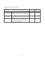
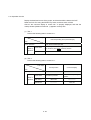
Relevant manuals
The following table lists the relevant manuals for this product.
Refer to this table as needed.
Manual Number
(Model name code)
Manual Title
GT Designer2 Version2 Basic Operation/Data Transfer Manual (For GOT1000 Series)
(1)
Explanation of GT Designer2 installation operations, basic operations for drawing, and method of
data transfer to GOT1000
SH-080529ENG
(1D7M24)
(Sold separately)*
GT Designer2 Version2 Screen Design Manual (For GOT1000 Series) 1/3
GT Designer2 Version2 Screen Design Manual (For GOT1000 Series) 2/3
(2)
GT Designer2 Version2 Screen Design Manual (For GOT1000 Series) 3/3
Explanation of the specifications and settings of all GOT1000 Series Object Function
SH-080530ENG
(1D7M25)
(Sold separately)*
GOT1000 Series Connection Manual (1/2)GOT1000 Series Connection Manual (2/2)
(3)
Explanation of the Applicable System Configuration and cable making method for the GOT1000
SH-080532ENG
(1D7M26)
Series Connection Types
(Sold separately)*
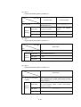
GT15 User's Manual
(4)
Explanation of Hardware Including All GT15 Main Body Parts Names, External Dimensions,
Installation, Electrical Wiring, Specifications, and an Introduction to Optional Equipment
(Sold separately)*
GT Converter2 Version2 Operating Manual
(5)
(1D7M23)
SH-080533ENG
Explanation of GT Converter2 operation methods
(Sold separately)*
GOT1000 Series Extended/Option Functions Manual
(6)
SH-080528ENG
Explanation of the extended/option functions that can be used in the GOT1000 Series
(Sold separately)*
(1D7M27)
SH-080544ENG
(1D7M32)
GOT1000 Series Gateway Functions Manual
(7)
Explanation of System Configuration, and Setting Method for the Gateway Function
Specifications
SH-080545ENG
(1D7M33)
(Sold separately)*
*Stored in GT Works2 and GT Designer2, in PDF Format.
(6)
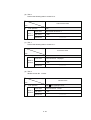
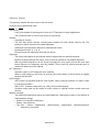
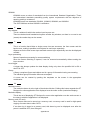
System Configuration in this Textbook
Output module
CPU module
Power supply module
Input module
Base unit Q3
B
A multiple CPU version of the Q series training machines is
composed of two CPUs.
QCPU
Q61P-A1 (CPU
No. 1)
QCPU*
(CPU
No. 2)
QX
QY
Q64
Q62
42
42P
AD
DA
(64
(64
(16
(16
points) points) points) points)
X0
to
X3F
Y40
to
Y7F
Parameters need to be set in GX Developer to enable multiple
CPUs to operate. Set paramters by following the procedures
described below to write to both No. 1 and No. 2 of QCPU.
<Caution: The following settings are not required unless
a multiple CPU system is used.>
<Setting procedure>
1) Doubleclick [PLC parameter] from the project list
in GX Developer.
2) When the Qn (H) parameter setting appears, click the multiple
CPU setting button.
3) Set "the number of CPUs" to "2" in the multiple CPU
setting dialog box.
4) Click the setting completed button.
I/O panel
BCD digital display (four digits x 2)
Extension cable
GT15-QC12B
Y40 to Y5F
Y5C Y58 Y54 Y50
to
to
to
to
Y5F Y5B Y57 Y53
Bus connection unit
GT15-75QBUSL
Y4C Y48 Y44 Y40
to
to
to
to
Y4F Y4B Y47 Y43
BCD digital display
Y6C Y68 Y64 Y60
to
to
to
to
Y6F Y6B Y67 Y63
Y60 to Y6F
LED x 8
GT1585-STBA
USB cable
GT09-C20USB-5P
Y70 to Y77
Y77 Y76 Y75 Y74 Y73 Y72 Y71 Y70
LED x 8
Y78 to Y7F
Y7F Y7E Y7D Y7C Y7B Y7A Y79 Y78
BCD digital switch (four digits x 2)
8
8
8
8
8
X3C X38 X34 X30
to to to to
X3F X3B X37 X33
X20 to X3F
8
8
8
X2C X28 X24 X20
to to to to
X2F X2B X27 X23
Snap switch (x 8)
PC
The PLC can also be monitored by
GX Developer or any other relevant
software via direct connection between
the PC and the PLC through an
RS-232 cable.
X0 to X7
X7
X6
X5
X4
X3
X2
X1
X0
XC
XB
XA
X9
X8
Snap switch (x 8)
X8 to XF
XF
(7)
XE
XD
Notes
(8)
Chapter 1 What is the GOT?
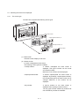
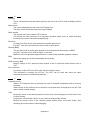
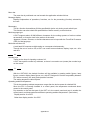
1.1
About the GOT
The GOT (Graphic Operation Terminal) can be used as an electronic operation panel
that enables such as switch operation, lamp display, data display, and message
display on the monitor screen, which had been conventionally implemented with a
control box.
Space saving
Cost reduction
(The illustration shows GT15
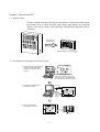
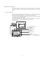
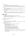
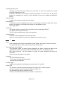
1.2
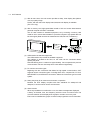
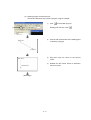
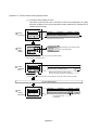
Procedures for monitoring the PLC CPU by GOT
1) Create a screen to be displayed
in GOT using GT Designer2,
software for creating monitor
screens.
Operation
lamp
Operation Stop
Data
Operation Stop
Operation
lamp
0
Data
0
Display pane figures known as
objects-such as the switch figure,
lamp figure, and numerical display,
etc.-are pasted to create the screen.
PC
2) Transfer the created monitor
screen data to GOT.
(CF card)
Operation Stop Operation lamp
USB
Cable
(RS-232C
Cable)
PC
3) Start monitoring after
connecting to PLC CPU.
Operation Stop
Data
Data
0
GOT
Operation
lamp
600
GOT
1-1
PLC CPU
.)
1.3
GOT features
(1) With its 256 colors, the color screen provides a sharp, clear display that yields a
vivid, top quality image.
Further, with the multi-color display board, 65,536-color display is available.
(For GT15 only)
(2) With a memory card, high-speed data transfer of OS and screen data between
personal computer and GOT is available.
The CF card interface is standard equipment, so by mounting a memory card
made for OS or screen data created on a personal computer, high-speed data can
be exchanged. (Data can also be transferred via USB, RS-232, or Ethernet.)
Memory
card
(CF card
)
(3) USB interface as standard equipment
The USB interface is provided as standard equipment.
The interface is located at the front, so the cable can be connected without
opening the panel.
Data transferring time is reduced to approximately 1/20 compared with previous
communication: RS-232. And setup time is also reduced significantly.
(4) For various connection types
Beginning with bus connection that allows for high-speed communication, GOT
supports various connection types—including direct CPU, computer link, CC-Link,
MELSECNET/10, and Ethernet connections. Select the connection type to suit the
system.
(5) Heavy-duty body for an extreme environment or operation
Because the GOT display complies with IP67 standards for waterproof and
dustproof, it can be used in various environments.
(6) Alarm function
When any breakdown or malfunction occur, the alarm messages are displayed.
A history of the date, time, and frequency which the error occurred is held. The
occurrence status can be displayed as a graph or saved to a memory card.
Errors can be classified into groups or levels to help organize the error information.
1-2
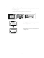
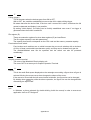
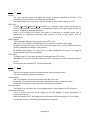
(7) Parts overlay (Layer function)
With the layer function, parts(objects/figures) can be superimposed, which
increases design flexibility.
For example, fluctuating numeric values and graphs, trend graphs and bar graphs,
image data and pointers can be superimposed and displayed together.
Front layer
Back layer
Actual view
(8) Expressive font variation
Two types of fonts are available: Mincho and Gothic.
®
TrueType fonts and Windows fonts are also available to display from small
characters to large characters truly.
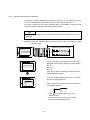
(9) Language switching function
The comment display created every language can be switched according to the
device value.
Screens which all the characters on the screen switch to Japanese, English, and
Korean are easy to create with a touch switch.
Switching language with the device.
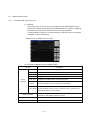
(10) Debug with enhanced compatibility with Mitsubishi PLC
All debug functions can be used to install the extended function OS to GOT from
GT Designer2.
Function Name
Ladder Monitor Function
System monitor function
Network Monitor Function
Intelligent Module Monitor
Function
Servo Amplifier Monitor
Function
CNC Monitor Function
Q Motion Monitor Function
List Editor for A/List Editor
for FX
Description
The sequence program can be monitored in ladder format.
The primary source of coil ON/OFF status, the device, and contact point can be searched.
Controller devices can be monitored and modified.
A function designed to increase the efficiency of maintenance operations so that maintenance can be
performed to resolve trouble with the controller system.
As MELSECNET line conditions are displayed, communication conditions can be checked by GOT only.
The data of the intelligent function module buffer memory can be monitored and changed using a
dedicated screen.
The I/O module signal condition can also be monitored.
The parameter settings and reference/diagnosis of the error history for the servo amplifier connected by
GOT can be performed.
The Position Display Monitor, Alarm Diagnosis Monitor, Tool Offset/Param, Program Monitor, and APLC
release screen that are equal to those of MELDAS dedicated display device can be displayed on the
MELDAS connected to GOT.
The Q motion controller CPU Servo Monitor and parameter settings can be performed on the GOT
screen.
MELSEC-A series, FX series sequence program can be edited in list (instruction word) format.
Program changes can be made without peripheral.
1-3
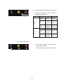
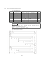
1.4
GOT function list
The table below shows the list function for each GOT model.
1-4
1-5
1.5
Applicable connection type between the GOT and the PLC CPU
The GOT can perform monitoring by connecting it to the PLC using the following
connection types.
Therefore, the connection type suitable for the system configuration or usage can be
selected.
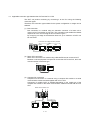
(1) Bus connection
Bus connection is a method using an extension connector of a base unit to
connect a GOT (connection by I/O bus). This connection type enables the fastest
response to a PLC CPU among all GOT connection types.
By occupying one stage of the extension base unit, up to maximum 5 GOTs can
be connected.
Connection to multiple GOTs is possible.
QCPU
GOT
GOT
GOT
(2) Direct CPU connection
Direct CPU connection is a method using a RS-232/RS-422 to connect a GOT.
Because no other equipment is required to connect the GOT to the PLC, this is the
most economical connection type.
PLC
GOT
(3) Computer link connection
Computer link connection is a method using a computer link module or a serial
communication module mounted together with a PLC CPU.
Connection of multiple GOTs is available depending on the model type of the
computer link module or the serial communication module mounted with the PLC
CPU.
Serial communication unit
PLC
GOT
GOT
1-6
GOT
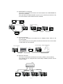
(4) MELSECNET/10 connection
GOT can be connected to the network as a normal station of the MELSECNET/10
(PLC to PLC network).
The cyclic data of the MELSECNET/10 (PLC to PLC network) and devices of the
PLC CPU within the same network can be monitored.
GOT
QCPU
GOT
Optical loop system
QCPU
Coaxial bus system
QCPU
GOT
QCPU
GOT
GOT
(5) CC-Link connection
GOT can be connected to the network as an intelligent device station of the
CC-Link System.
The cyclic data of the CC-Link System and devices of the PLC CPU on the master
or local station can be monitored.
CC-Link module
CC-Link module
QCPU
Remote I/O station
Partner manufacturer
Local station
GOT
(6) Ethernet connection
GOT can be connected to the Ethernet connection (UDP/IP communications).
The networks can be configured with commercially available products such as
hubs and cables.
Hub
GOT
QCPU
QCPU
1-7
QCPU
(7) Applicable connections with third party PLCs
GOT can be connected to third party PLCs.
The system construction without regarding to PLC manufacture is available.
Refer to the product catalogue or manual about PLC models that can be
connected.
(8) Connection to equipment other than the PLC
● Microcomputer
Data can be read and written from a personal computer, microcomputer board,
PLC to GOT virtual devices.
● Bar-code reader
The data read with the bar-code reader can be written to PLC CPU.
● Temperature controller, Inverter, Servo amplifier, CNC
The controllers can be monitored and changed the parameters.
(9) Multi-channel function
The GOT which installs multiple communication drivers can be monitored up to
maximum 4 (4 channels) controllers (PLC CPU, temperature controller, inverter,
etc.).
Install multiple
communication drivers.
Channel No. 1
Bus connection
Channel No. 2
OMRON
PLC connection
Channel No. 3
Temperature
controller connection
Channel No. 4
Servo amplifier
connection
1-8
Monitor devices
for controllers
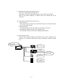
1.6
Equipments required for using GOT
The equipment required to connect the GOT to the PLC CPU is shown below.
USB cable,
RS-232 cable
Memory card, Ethernet cable
Connection cable
Screen data transfer
Connection
PLC CPU
PC
The Ethernet communication
unit is necessary to connect
via an Ethernet cable.
(The illustration shows GT15
Equipment Name
.)
Application
[1] Personal computer
Writing the screen data to GOT.
[2] GT Designer2
Software to create screen data
[3] USB/Cable
Cable to connect with the personal computer and GOT *1
[4] Communication Unit
Unit to connect the PLC CPU connection cable *1
[5] Connection Cable
Cable to connect with the GOT and PLC CPU *2
*1
*2
The communication unit varies depending on the PLC connection type.
When connecting to the PLC with the RS-232 port built-in on GOT (direct CPU connection,
computer link connection, etc.), the communication unit is not required.
The connection cable varies depending on the connection type.
The connection cables used for each connection type are shown below.
Connection Type
Bus Connection
Connection Cable *1
Bus Connection Cable
Direct CPU Connection
For RS-232 Connection
RS-232 Cable
For RS-422 Connection
RS-422 Cable
RS-232/422 Conversion Cable
Computer Link Connection
For RS-232 Connection
RS-232 Cable
For RS-422 Connection
RS-422 Cable
RS-232/422 Conversion Cable
CC-Link Connection
CC-Link Dedicated Cable
MELSECNET/10 Connection
For Optical Fiber Cable Connection
Optical Fiber Cable
For Coaxial Cable Connection
Coaxial Cable
Ethernet Connection
*1
Ethernet Cable
The connection cables are exclusive products.
(Only the Ethernet connection cable is commercially available.)
1-9
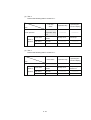
Personal computer
The personal computer is for creating and downloading the GOT1000 screen data.
Item
Description
PC/AT compatible personal computer on which Windows® will operate
PC
Microsoft® Windows® 98 operating system English version
Microsoft® Windows® Millennium Edition operating system English version
Microsoft® Windows® Workstation 4.0 operating system English version *2
Microsoft® Windows® 2000 Professional operating system English version *2
OS
Microsoft® Windows® XP Professional operating system English version *1 *2
Microsoft® Windows® XP Home Edition operating system English version *1 *2
Computer
Refer to *3 below.
CPU
Required Memory
Hard Disk Space
For Installation: 300MB or more
For execution: 100MB or more
Disk Drive
CD-ROM Disk Drive
Display Color
High Color (16 bits) or more
Display
Resolution 800 × 600 dots or more
Internet Explorer Ver 5.0 or later must be installed.
Others
*1
*2
*3
Mouse, Keyboard, Printer and CD-ROM Driver should be compatible with the above OS.
”Compatibility mode”, “Fast user switching”, “Changing desktop themes (font)” and “Remote desktop” are not supported.
®
®
The Administrator authority is required to install GT Designer2 into Windows NT Workstation 4.0, Windows 2000 Professional,
®
®
Windows XP Professional or Windows XP Home Edition.
®
®
The Administrator authority is also required to use GT Designer2 on Windows XP Professional or Windows XP Home Edition.
The PC performance requirements are shown below, according to the operating system to be used.
Performance required for personal computer
Operating System
CPU
Required Memory
Microsoft® Windows® 98 operating system English version
Pentium® 200MHz or higher
64MB or more
Microsoft® Windows® Millennium Edition operating system English version
Pentium® 200MHz or higher
64MB or more
Pentium® 200MHz or higher
64MB or more
Pentium® 200MHz or higher
64MB or more
Pentium II ® 300MHz or higher
128MB or more
Microsoft® Windows® NT® Workstation 4.0 operating system English
version
Microsoft® Windows® 2000 Professional operating system English version
®
®
Microsoft Windows XP Professional operating system English version
Microsoft® Windows® XP Home Edition operating system English version
1 - 10
GT Works2 and GT Designer2 (CD-ROM)
Product Name
Products included
GT Designer2
GT Works2
Version
GT Designer2
Version
Creates screens for the GOT1000 series and GOT900 series.
Enables to operate as the GOT-A900 series on the personal
GT SoftGOT2
computer.(The License key or License FD is required to use this
software.)
Enables the simulation of GOT-A900 series or GOT1000 series
GT Simulator2
operation on a personal computer by connecting with GX simulator
or PLC CPU.
Converts the project data for GOT-800 series or Digital Electronics
GT Converter2
Corporation’s package data into a GT Designer2 format file.
GT Converter2 is not required to convert the project data for
GOT900 series to those for GOT1000 series.
1 - 11
—
Notes
1 - 12
Chapter 2 GOT Operation
GOT enables reading and writing to PLC CPU device memory (bit, word) with the
switches, lamp display, numerical display/input, message display, etc. on the GOT
screen.
2.1
Summary of operation
With GT Designer2, display pane figures called objects: —such as the switch figure,
lamp figure, and numerical display, etc., —are pasted on the GOT screen.
GOT functions can be executed by setting operation functions of the PLC CPU device
memory (bit, word) to each pasted object.
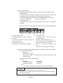
This chapter explains the GOT operation in connection with the PLC CPU when the
switch (touch switch) or numerical display are set as shown below.
<System example>
Sequence program
PLC CPU
M0
M1
Y10
Y10
Y10
<Settings of GOT for figures>
MOV K123 D10
Bus connection cable
Touch switch setting
Bit momentary
Write device : M0
Touch switch setting
Bit momentary
Write device : M1
Operation Stop Operation Lamp
Lamp display setting
Bit
Read device : Y10
Data 1 123
Numerical display
Read device : D10, unsigned BIN
Display
: Unsigned decimal number
GT15
2-1
<Action description>
(1) While the touch switch "Operation" on the
GOT is being touched, the bit device “M0” has
been ON.
(PLC CPU)
(GOT)
Turns ON.
Touch.
M0
Operation Stop Operation Lamp
M1
Y10
Y10
Y10
Data 0
MOV K123 D10
(2) When the bit device "M0" turns ON, the bit
device "Y10" turns ON.
(PLC CPU)
(GOT)
Turn ON.
Turns ON.
M0
Operation Stop
Operation Lamp
M1
Y10
Also, the ON figure is displayed on Operation
Lamp in which the monitor device has been
set to the bit device "Y10".
Y10
Y10
Data 0
MOV K123 D10
(3) As the bit device "Y10" has been ON, "123" is
stored into the word device “D10”.
(PLC CPU)
(GOT)
"123" is displayed.
"123" is stored into D10.
M0
Operation Stop Operation Lamp
M1
Y10
"123" is also displayed in the numerical
display on the GOT in which the monitor
device has been set to the word device "D10".
Y10
Y10
Data 123
MOV K123 D10
(4) While the touch switch "Stop" on the GOT is
been touched, the PLC CPU bit device “M1”
has been ON.
The PLC CPU bit device "Y10" turns OFF,
and Operation Lamp turns OFF.
(PLC CPU)
(GOT)
Touch.
M1 turns ON. Y10 turns OFF.
M0
Operation Stop
Operation Lamp
Display turns OFF.
Data 123
M1
Y10
Y10
Y10
MOV K123 D10
2-2
2.2
2.2.1
Entering numerical values into PLC CPU
Numerical input function
The function that writes an arbitrary numerical value into a specified word device.
While not inputting the numerical value, current value of the numerical input has been
displayed.
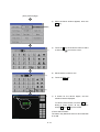
The Key window of the GOT is used to input numerical values.
Input the numerical value by displaying the below key window whose is prepared in
GOT. (User-created key window is also available.)
Numerical input key window
For entering decimal numbers
For entering hexadecimal numbers
1)
2)
1) : Numbers are displayed as you enter them.
2) : Input range for data is displayed.
Point
User-created key window for numerical input is created by registering the
window as the key window.
The registered key window is displayed instead of the standard key window.
Refer to GT Designer2 Version2 Screen Design Manual chapter 4 for details of
user-created key window.
2-3
1)
2)
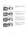
2.2.2
How to operate numerical input
Touch the numerical input to be input.
D100 100
D200 100
Input the numerical value on the key window to be displayed.
To store the value, touch RET key.
D100 200
0
D200 100
The input numerical value is reflected (D100: 100 → 200), and
the key window is closed.
D100 200
D200 100
Point
The display and operation of the cursor and key window for numerical input can
be changed through settings.
(1) Display or non-display of the cursor, and key window
• When establishing conditions or switching screens, the cursor and key
window are displayed, and when establishing the operating conditions,
the cursor and window key are not displayed.
• The key window is displayed on touch input and not displayed at
pressing RET key.
(2) Cursor key operations
The input order can be set to the multiple numerical input.
100
0
100
0
0
0
0
Input fixation
Move cursor to the
next input field.
Refer to GT Designer2 Version2 Screen Design Manual chapter 4 for the
operation setting methods of cursor and key window for numerical input.
2-4
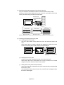
2.3
2.3.1
Switching the screen to be displayed
The screen type
The GOT1000 comprises the following screen types.
n status
Productio
A 1254
screen 1
B 348
Base screen
n status
Productio
A 1254
screen 1
superimposed window 1,2
B 348
Back
n status
Productio
A 1254
screen 1
B 348
Overlap window 1, 2
Key window
Front
(1) Base screen
The basic screen display on the GOT.
(2) Window screen
A screen overlapped the base screen.
The following screen types are available.
• Overlap window :
A window overlapped the base screen is
displayed. This type of window can be moved
and closed manually.
Maximum of two screens can be displayed.
• Superimposed window :
A window superimposed the base screen is
displayed. By switching a superimposed window,
the corresponding part of the base screen can be
changed. Maximum of two screens can be
displayed.
• Key window :
A pop-up window on the base screen is
displayed when inputting numerical values.
Two key types window: default key window and
user-created key window are available.
2-5
Remarks
• Maximum of 32767 screens of both the base screen and the window screen
can be created.
Maximum of 4096 base screens and 1024 window screens can be displayed
on the GOT.
• Refer to GT Designer2 Version2 Screen Design Manual chapter 2 for settings
including window screen display position.
2.3.2
Screen switching device
The screen switching device is set to switch the base screens or to display the window
screen on the GOT.
Device types for screen switching are as follows.
• Device for base screen switching
• Device for overlap window1 switching
• Device for overlap window2 switching
• Device for superimposed window1 switching
• Device for superimposed window2 switching
(1) Switching base screens
Switch base screens by setting a base screen No. to the device for base screen
switching.
Example: When the switching device for base screen is D100.
Base screen 10
Base screen 20
Device value
changed
D100
10
D100
Base screen whose
No.is same with
screen swith device
value appears
20
(2) Displaying or non-displaying window screen
Switch window screens by setting a window screen No. to the device for window
screen switching. It stores 0 and then erases the window screens.
Example: When the switching device for window screen is D120
Windows screen No.1 displayed
Windows screen No.2 displayed
Overlap windows 1 not displayed
13451
D120
D120
1
2
D120
0
Remarks
• Refer to section 4.2.3 for setting methods of screen switching device.
2-6
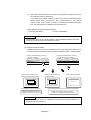
2.3.3
Base screen switching with the sequence program
GOT display screen is switched when the screen switching device value is written with
the sequence program.
Example: When the switching device for base screen is D0
Sequence program example
X1
X2
Screen No. 6
X2
Data 2 1234
D0
MOV K3
D0
X1
The current value of D0 is stored six because the
GOT displays screen No. 6.
Turn on X1 with the sequence program, and D0
value is changed to two.
Screen No. 6
Data 2
MOV K2
1234
The GOT displays screen No. 2 because D0 value
is changed to two.
Screen No. 2
Operation Stop
2-7
2.3.4
Base screen switching with the touch switch
GOT display screen is switched when the screen switching device value is written with
the touch switch.
Example: In the case of device for base screen switching: D0
Screen No. 5
Operation lamp
No.10
Touch switch setting
Operation setting: Base switching
Fixed to "10"
The current value of D0 is stored five because the
GOT displays screen No. 5.
Set both of X1 and X2 in OFF with sequence
program, and touch No. 10 touch switch.
Screen No. 5
Operation lamp
No.10
The GOT displays screen No. 10 because the
current value of D0 is changed to 10 with the touch
switch.
Screen No. 10
Stop
2-8
2.3.5
Window screen display and switching
The window screen is displayed by writing the same No. as the window No. of the
screen to be displayed into the switching device used in overlap windows 1, 2.
Two types of writing in the screen switching device are available : writing with the
sequence program, and writing with the GOT touch switch.
Point
When "zero" is written in the screen switching device, the window screen is not
displayed.
Example: When the switching device for base screen is D0, and that for overlap
window 1 is D1.
Sequence program example
X3
Screen No. 15
Data 4
999
X4
MOV K3
D1
MOV K0
D1
X3
The current values of the switching device are the
below because the GOT displays only base screen
No. 15.
D0 = "15"
D1 = "0"
Turn ON X3 with the sequence program, and D1
value is changed to three.
Screen No. 15
Data 4
X4
999
The GOT displays window screen No. 3 because
D1 value is changed to three.
Screen No. 15
Data
4 Screen
Window
No. 3
When closing the window screen, operate either of
the following methods.
Window Screen
No. 3
in the upper right corner of the
• Touch
window screen.
• Write "zero" as the D1 value in the overlap
window1 screen switching device.
2-9
Notes
2 - 10
Chapter 3 About GT Designer2
3.1
About GT Designer2
The screens displayed in the GOT are designed with the GT Designer2.
Drawing is to place or set figures and objects on the GT Designer 2 screen.
The created screens and system data required for GOT operation are transferred to
the GOT by GT Designer2.
Data transfer
GT Designer2
GOT
Download (write)
Screen
data
Upload (read)
Data for system
(Boot OS,
OS, etc.)
Draw a screen for GOT.
Screen created with GT Designer2 is displayed.
Install
3.2
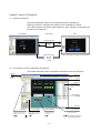
GT Designer 2 screen configuration and features
This chapter describes screen configuration and features of the GT Designer2.
Title bar
Menu bar
Toolbars
Title bar
Data View
All object functions
and figures on the
screen are displayed
in a list.
Created screen
(Editor)
Status Bar
Workspace
Settings on the overall project
such as created screen and
common settings are displayed
in tree.
Property sheet
Attributes of selected
screen, objects and figures
are displayed.
Settings can be made here.
Library Image list
Library is displayed.
Objects/figures in library
can be pasted.
Part Image list
Parts used in the part display
function are displayed.
GT Designer2 Version
Screen Design Manual
This Section 3
Section 7.7.7
3-1
(1) Easy understanding of the overall project (workspace)
The overall project settings are displayed in a tree structure.
It is convenient to confirm the settings, to check progress of work, and to copy the
screen.
(2) Management of objects according to application (category)
The overall project settings are displayed in a tree structure according to
application (category).
Classification for each application allows simple management of objects.
(3) Shortest setting without opening dialog box (property sheet)
Without opening the dialog boxes for the selected objects and figures, all setting
items and setting details are displayed in a list.
Setting without
opening dialog box
(4) Registration of frequently used parts (library registration)
Frequently used objects and figures can be registered.
Registered objects or figures can be dragged and pasted onto the screen.
(5) Data View
The Data View displays all objects and figures arranged on the screen in a list.
(6) Wizard application supporting required settings (new project wizard)
When creating a new project, an interactive wizard appears.
By following the interactive wizard, the settings required for the GOT1000 can be
completed.
Wizard start
System setting. Screen
switching device. Multiple
controllers can easily be set.
Confirm the settings in the list.
3-2
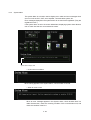
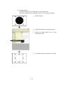
(7) Easy confirmation of images with preview.
Display images that are the same as those for GOT (language switching, security
level changing, object ON/OFF setting, etc.) can be displayed and confirmed with
GT Designer2.
Example: Switch the language
Comment Group Column No.
Select column No. of comment group to display.
Select column No. 1.
3-3
Select column No. 2.
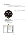
3.3
How to use the online manual
The online manual is contained in the product CD-ROM in PDF data.
To view the PDF data, Adobe® Acrobat® Reader® must have been installed in the
personal computer.
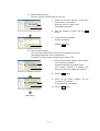
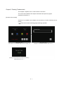
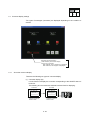
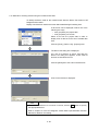
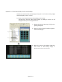
3.3.1
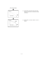
Reading the online manual from the product CD-ROM
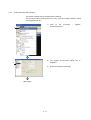
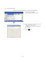
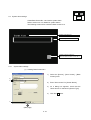
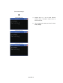
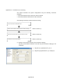
(1) Operation procedures
1)
Click GT Manual 1000 in the GT Manual
Menu.
2)
As the INDEX MENU screen is displayed,
click the manual to be viewed.
3)
The selected manual is displayed.
Click the manual to be viewed.
3-4
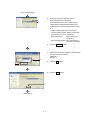
Remarks
The online manual can be viewed from the Start menu or GT Designer2 Help
after installation of the GT Manual to the personal computer.
Refer to the next page for how to view it from Help.
(GT series)
Click.
3-5
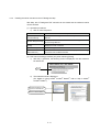
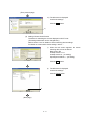
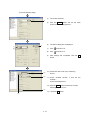
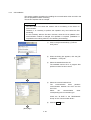
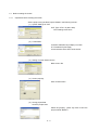
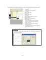
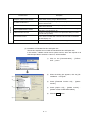
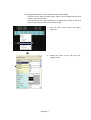
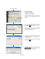
3.3.2
Reading the online manual from the GT Designer2 Help
With Help, the GT Designer2 PDF manuals can be viewed and the software version
can be checked.
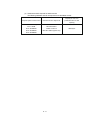
(1) Operation procedures
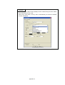
1) Click on each Help menu.
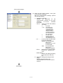
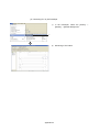
Item
[Basic
Operation/Data
Transfer Manual]
[Screen Design Manual]
Description
Displays the GT Designer2 Version Basic Operation/Data Transfer
Manual.
Displays the first/second volume of the GT Designer2 Version
Screen Design Manual.
[Index]
Displays the PDF manual list.
[About GTD2...]
The GT Designer2 version can be confirmed.
[Connect to
Connects to the Mitsubishi Electric FA Equipment Technology
MELFANSweb...]
Information Service MELFANSweb.
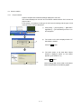
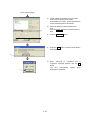
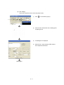
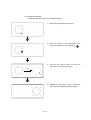
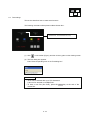
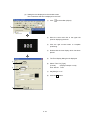
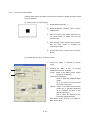
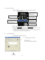
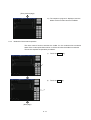
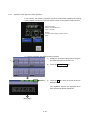
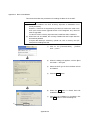
(2) PDF manual viewing procedure (only when selecting [Index])
1) After the (1) operation, the following screen is displayed, click the manual to
be referenced.
Click.
2)
The selected manual is displayed.
(For details on using Adobe® Acrobat® Reader®, refer to Help in Adobe®
Acrobat® Reader®.)
Switches the display to the
page of the selected item.
Returns to INDEX MENU.
3-6
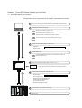
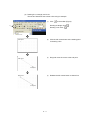
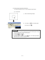
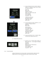
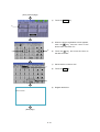
Chapter 4 From GOT Screen Creation up to the Test
4.1
Preparation before using the GOT
The procedures up to monitor the PLC by the GOT is described in this section.
1
Install the GT Designer2 software package
(refer to the GT Designer2 Version2 Basic Operation/Data Transfer Manual).
2
Create project data (GT Designer2).
3
1
Create project (Refer to section 4.2.1).
(Setting GOT/PC (PLC) type to use)
2
Set controllers (Refer to section 4.2.2.)
(select connection method between GOT and PLC)
3
Screen switching device settings (Refer to section 4.2.3).
4
Create screen data for user (Refer to section 4.2.4)
Connect the PC and GOT (Refer to section 4.3.1)
USB cable
RS-232 Cable
Ethernet Cable
4
5
* USB cables are used during training.
Transfer data to GOT
1
Install OS (standard monitor OS), PC communication drivers, etc.
(Refer to section 4.3.3)
2
Download project data (Refer to section 4.3.5)
Mount communication interface (Refer to section 4.4.1) *1
*1 This is not required when an RS-232 is used for connection.
6
Connect GOT and PLC (Refer to section 4.4.2)
RS-232 Cable
* Bus connection cables are used during training.
RS-422 Cable
Bus connection cable
Optical fiber cable (MELSECNET/10)
Coaxial cable (MELSECNET/10)
CC-Link dedicated cable
10BASE-T/100BASE-TX cable
7
Communication check (refer to section 4.5).
8
Monitor start
4-1
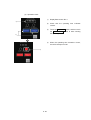
4.2
4.2.1
Screen creation
Project creation
Projects comprise all the data and settings displayed in one GOT.
The screens displayed in the GOT and connection method with the PLC are set in a
project wizard.
In this section, the settings for the type of GOT used for training and the type of PLC
connected to the GOT are described.
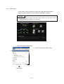
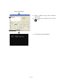
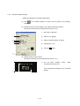
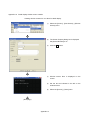
1)
Click [Start] → [All Programs] → [MELSOFT
Application] → [GT Simulator2] menus to run
GT Designer2.
2)
The screen on the left is displayed when GT
Simulator2 is started.
1)
2)
Click the New button.
3)
The initial screen of the Start New Project
Wizard is displayed. (When no new wizard
appears, go to section 4.2.2.)
Click the Next button.
3)
Various settings that can be made on the project
wizard are described on the following pages.
4-2
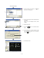
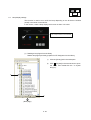
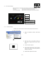
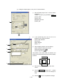
(1) System settings for GOT
The GOT type to be used and the color are set.
1)
When the left screen appears, set the GOT
type and the color as follows.
GOT type: GT15**-S (800 × 600)
Color setting: 256 colors
2)
After the selection is made, click the Next
button.
3)
The left screen is displayed.
Confirm the settings.
1)
2)
Click the Next button.
3)
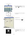
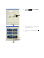
(2) Communication Settings
The connection method for the device to be connected to GOT is set.
(The settings made here can be changed later.)
For details on communication settings, refer to section 4.2.2.
1)
When the left screen appears, set the device
to be connected as follows.
Controller: MELSEC-Q (multi)/Q motion
(The training machine is a multiple CPU
system, so select the multiple CPU system.)
2)
Click the Next button.
3)
When the left screen appears, set the
connection I/F as follows.
I/F: Extended I/F-1 (first stage)
4)
Click the Next button.
1)
2)
3)
4)
(Next page)
4-3
(From previous page)
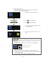
5)
5)
6)
When the left screen appears, set the
communication driver as follows.
Communication driver: Bus connection Q
<Note: Always change default setting from
"A/QnA/QCPU, QJ71C24" to Bus connection
Q. >
• There are two types of bus connection
communication drivers. Select a driver that
matches the PLC to be connected.
Bus connection Q
: With connection to
the QCPU
Bus connection A/QnA : With connection to
the ACPU, QnACPU
6)
Click the Details… button.
7)
When the left screen appears, set the Stage
No. and Slot No. as follows.
Stage No.: 1
Slot No.: 0
8)
Click the OK button.
9)
Click the Next button.
7)
8)
9)
(Next page)
4-4
(From previous page)
10) The left screen is displayed.
Confirm the settings.
Click the Next button.
10)
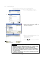
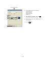
(3) Setting of Screen Switch Device
The device for switching the screens displayed on GOT is set.
(The settings made here can be changed later.)
Refer to section 4.2.3 for details on screen switching device settings.
For details on screen switch device settings, refer to ~.
1)
1)
When the left screen appears, the screen
switching device is set as follows.
Base screen: D0
Overlap window 1: D1
Overlap window 2: - (no setting)
Superimpose window 1: - (no setting)
Superimpose window 2: - (no setting)
Click the Next button.
2)
The left screen is displayed.
Confirm the settings.
Click the Finish button.
2)
(Next page)
4-5
(From previous page)
(4) Screen property
The base screen is created.
1)
The Screen Property dialog box is displayed.
Set the base screen1 title.
2)
Enter a character string as the screen name.
Enter "Base Screen" here.
3)
Click the OK button.
4)
Base screen1 is created.
The screen is ready for drawing.
Point
Up to 32 characters can be entered as a screen name, regardless of whether
they are one-byte or two-byte characters.
Remarks
(1) The GOT/PC type and screen names can be changed
GOT/PC type and screen title settings can be changed in the project
workspace.
• Changing the GOT/PC type
• Changing the screen name
1) Right click
Double click
2) Update the screen title.
Change directly.
Screen properties
Changing with dialog box
(2) Refer to chapter 7 of the GT Designer2 Version2 Basic Operation/Data
Transfer Manual for details on GOT/PC type and screen name settings.
4-6
4.2.2
Communication Settings
Point
Settings described in this section are not required when settings are made on the
new project wizard (Section 4.2.1).
The GOT and PLC CPU communication settings are performed.
When the GOT is used first, set the channel No. of the communication interface and
the communication driver, and download the settings to the GOT.
This section explains about using a bus connection between the GOT and CPU.
1)
Double-click [Common Settings] → [System
Environment] menu in the project workspace.
2)
When the System Environment screen
appears,
double-click
[Communication
Settings].
Double-click.
(Next page)
4-7
(From previous page)
(3) When the left screen appears, check [Use
Communication Settings].
With the Communication Settings, perform
the following settings.
1)
•
•
•
•
2)
(Next page)
4-8
Standard I/F Settings
Settings are performed for the
communication interface on the GOT
(Standard
I/F-1:R-232,
Standard
I/F-2:USB).
CH No. ···· Select a CH No. that matches
the usage.
0
: not used
1 to 4 : FA device, for
microcomputer
connection (The
communication
settings must be
made according to
the channel No. to
be connected)
8
: For bar code
reader connection
9
: For host (PC)
connection (default)
I/F ············ Communication interface type
is (2 types) displayed.
RS232 : For communication
with PC (GT
Designer2), PLC, and
microcomputer.
USB : For communication
with PC (GT
Designer2). (default)
Driver······· Select the PC communication
driver to be installed in the
GOT.
Detail setting····
Perform the settings including
driver baud rate, data size,
etc.
Extend I/F Settings (first stage to third
stage)
Settings are performed for the
communication unit in the GOT extend
interface.
(From previous page)
• CH No. ····· Select a CH No. that matches
the usage.
0
: not used
1 to 4 : FA device, for
microcomputer
settings (settings to
match the channel
No. for connecting
the controller)
* : Gateway function, for
Ethernet download
• Driver·········Select the PC communication
driver to be installed in the
GOT.
• Detail setting········
Perform settings including
driver stage No., slot No., etc.
4)
Extend I/F Settings.
Set the 1st stage extend I/F1-1 as described
below.
(Settings for this item have already been
performed in the new project wizard described
in section 4.2.1.)
CH No.: 1
Driver: Bus connection Q
5)
Click the Detail Setting… button.
6)
When the left screen appears, set the stage
No. and slot No. as follows.
(Settings for this item have already been
performed in the new project wizard described
in section 4.2.1.)
Stage No.: 1
Slot No.: 0
7)
Click the OK button.
4)
5)
6)
7)
4-9
Point
Settings including QCPU (Q mode) Stage No. and Slot No.
With a bus connection, the PLC CPU recognizes the GOT as a 16 I/O point
intelligent function module.
A free PLC CPU I/O slot is allocated to the GOT, but when the PLC CPU
connected is a QCPU, no free basic base/extended base I/O slot can be
allocated.
On communication settings, build one stage(16 points ×10 slot allotment) for
GOT connection, so that the GOT can be allocated to an I/O slot.
Remarks
• Refer to chapter 3 of the GT Designer2 Version2 Screen Design Manual for
details on Communication Settings.
• Controller settings can also be performed with the GOT Utility.
Refer to the GOT1000 Connection Manual for details on Utility Communication
Settings.
4 - 10
4.2.3
Screen switching device settings
This section explains screen switching device settings.
Set the base screen switching device to "D0", and the Overlap window1 screen
switching device to "D1".
1)
Click on the [Common]
Environment] menu.
–
[System
2)
The System Environment dialog box is
displayed.
3)
Double click [Screen Switching].
1)
3)
(Next page)
4 - 11
(From the previous page)
4)
The screen switches.
5)
Click the Dev… button and set the base
screen screen switching device.
6)
The device dialog box is displayed.
7)
Click
and set to "D".
8)
Click
and set to "0".
9)
After settings are completed, click the OK
button.
5)
9)
7)
8)
10)
12)
10) Check that "D0" is set in the "switching
device".
11) Check "Overlap window 1" and set the
Overlap 1
screen switching device.
12) Click the Dev… button and set the "screen
switching device" to "D1".
13)
13)
11)
4 - 12
Click the OK button.
Remarks
• Screen switching device settings
With the screen switching device, refer to the following to set the devices to be
used.
1) GOT internal device (GD)
It is recommended to use this device only for switching the screen with the
touch switch (screen switching switch).
Screen switching cannot be controlled by the PLC CPU.
With the screen switching device, the internal device (GD100) is set by
default.
2) PLC CPU device (D,W, etc.)
It is recommended to use this device to control screen switching from the
PLC CPU.
Screen switching can also be performed by the touch switch (screen switching
switch).
4 - 13
4.2.4
Data reading
In this section, training is performed using screen data prepared beforehand.
(Specific creation methods for screen data are explained in chapter 5.)
Remarks
The settings for the data to be read, "school.GTE", are the same as the
settings described in sections 4.2.1 and 4.2.2.
The screen (project data) is read.
1)
1)
(Next page)
4 - 14
Click on the [Project] – [Open] menu.
(From previous page)
2)
When the dialog box appears, click
then click "3½ Floppy [A:]".
, and
3)
Select the file format of the screen data file to
be opened.
Select the "GT Designer2 Files (*.GTD,
*.GTE)" .
4)
Select school.GTE
5)
Click the Open button. The screen data is
read.
6)
As the dialog box to confirm whether to save
the project data created this time appears,
click the No button.
7)
The screen is read.
2)
4)
5)
3)
6)
4 - 15
4.2.5
Saving the project data
This section explains operations to save the created project data.
This section explains with an example of saving to a floppy disk (A drive).
1)
Click on the [Project] – [Save As] menu.
2)
When the dialog box appears, click
then click "3½ Floppy [A:]".
3)
Enter the file name (project name) of the
screen data file to be saved.
Enter "BASIC" here.
4)
Click the Save button to save the screen data.
1)
, and
2)
3)
4)
Point
When the project data is saved, not only the created screen, but also common
settings such as connection settings, parts Information, etc., are saved in one file.
If saved files are copied onto another PC, they can be used as they are.
However, only the user-made library information is saved in a separate file, so
when using the user-made library information, it is necessary to make a separate
copy of the library data.
For details on saving the library, refer to the GT Designer2 Version2 Basic
Operation/Data Transfer Manual.
4 - 16
4.3
Data transfer (PC to GOT)
This section explains procedures for writing data created on GT Designer2 to the
GOT.
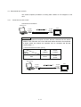
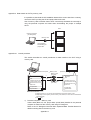
4.3.1
Connection from PC to GOT
Connect the PC and GOT.
Notebook PC
To USB
connector
To USB
connector
GOT
Remarks
To connect the personal computer and GOT, RS-232 or Ethernet can be used in
addition to the USB cable. Use of the USB cable enables the data to be transferred
at higher speed and reduces the operation time as compared with RS-232
communication. *1
*1 Download reference value: (GT15)
Connection method
Project
Data size
1MB
USB
RS-232
(12Mbps)
(115Kbps)
20 sec
2 min
30 sec
*2 When using the RS-232 cable, use the GT01-C30R2-9S.
Notebook PC
To USB
connector
4 - 17
To USB
connector
GOT
4.3.2
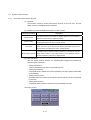
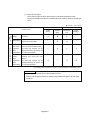
About data types transferred to the GOT
To operate the GOT, it is necessary to transfer the following types of data to the GOT.
Data type
Outline
Data transfer timing
Boot OS
The program needed to control GOT hardware, and during • When returning the
communication between GOT and PCs.Boot OS is installed in
settings of the GOT main
the GOT at factory shipment so installation is not usually
unit to the factory
necessary.
settings (normally,
installation is not required)
OS
The GOT monitoring function, OS/screen data installation,
OS/screen data deletion, touch key control, system screen/
guidance display function and other features for controlling the
GOT are installed.
Standard
monitor OS
(Required)
Communication
driver
(Required)
Extended
function OS
Option OS
Project data
(Required)
The programs that operate the GOT, e.g. interface control, • When using GOT for the
first time
OS/screen data installation, OS/project data deletion, touch key
• When changing the
control, and screen/guidance display functions.
functions to be used
The PC communication driver performs communication between
(Extended function, Option
the GOT and the PLC CPU. Always select and install a PC
OS) and communication
communication driver that is appropriate for the connection type.
format
•
After an OS upgrade
Needs to be installed when the extended function *1 is used.
2
Needs to be installed when functions * available by connecting
an option function board (including a board with extension
memory) or a multi-color display board are used.
Data for user-made monitor screens, such as screen data, • When using GOT for the
comments, common settings, etc.
first time
• When changing screens
and settings
Special data
Data used by the extended function (intelligent module/Q • When
changing
motion/servo amplifier monitor, etc.).
functions to be used
Resource data
All types of data created in the GOT main unit, such as recipe • Varies depending on each
file, alarm log file, etc.
GOT function
the
*1 Extended functions included the following.
• System monitor
• Bar code
*2 Option functions include the following.
• Advanced recipe
• Logging function
• Gateway function
• Object script
• Network monitor function
• Recipe function
• Standard font
• Intelligent module monitor function
• Maintenance report function
function
• List editor function
(Chinese: Simplified,
traditional)
• Multi-channel function
• Kana-kanji conversion
function
• Ladder monitor function
• Servo amplifier monitor
function
• CNC monitor function
• Q motion monitor function
Point
With GOT, data exchange between the PC and GOT is expressed in the following
terms.
• Download : Writing the project data created by PC to the GOT.
• Upload
: Reading the GOT project data on a PC.
• Install
: Writing the system data required to run GOT (BootOS, OS) to
GOT.
4 - 18
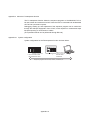
4.3.3
Communication settings
Settings for communication between the PC and the GOT are performed.
Communication configuration dialog box
4 - 19
1)
Click on the [Communication] –
[Communication configuration…] menu.
2)
When the dialog box appears, set the
communication type to "USB".
(In training, to connect the PC and GOT with
the USB cable)
3)
Click the OK button.
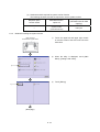
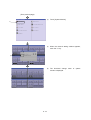
4.3.4
OS installation
This section explains operations for installing the communication driver and OS in the
GOT as preparation before monitoring.
This section explains with an example.
Point
The GOT does not include the monitor OS for monitoring or the driver for
communication.
Therefore, it is necessary to perform this operation only once before the first
monitoring.
It is not necessary after the first time. However, when the OS is updated or the
communication method is changed, this operation is required. (Installation is
completed on the training machine, so overwriting is necessary.)
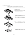
2)
3)
1)
Click on the [Communication] – [To/From
GOT] menu.
2)
When the dialog box appears, click the [OS
installation → GOT] tab.
3)
Select the standard monitor OS.
The standard monitor OS is a program that
performs monitor function control.
4)
Select the communication driver.
The
communication
driver
performs
communication between the GOT and the
PLC CPU.
Select
the
communication
driver
corresponding to the connection type.
Check the "Q BUS" in the "BUS/network
Group" of the "communication driver".
5)
(Next page)
4 - 20
Click the Install button.
(From previous page)
6)
When the Yes button
installation is executed.
7)
After OS installation is completed, click the
Close button to close the dialog box.
6)
is
clicked,
OS
Point
(1) Installing the OS
If the Standard monitor OS is not installed in the GOT (Boot OS is installed at
time of shipment), install the Communication drivers, Extended functions OS,
and Option OS after installing the Standard monitor OS.
(2) Downloading Project data and Special data
When the OS (Standard monitor OS, Communication driver, Extended
function OS, Option OS) used by GT Designer2 to which Project data and
Special data is downloaded is newer than the OS installed in the GOT, new
functions may be unavailable.
Reinstalling the OS is recommended when downloading Project data and
Special data to the GOT main unit.
(3) Installing the OS
The version numbers (both the major and minor version) of each OS
(Standard monitor OS, Communication driver, Extended function OS, Option
OS) must be the same.
If their version numbers are different, the GOT will not operate.
(Example1)
(Example2)
Standard monitor OS
Standard monitor OS
Communication driver
Communication driver
Extended function OS
Extended function OS
Option OS
Option OS
GOT is operated.
4 - 21
GOT is not operated.
4.3.5
Screen data download
This section explains operations for downloading the created screen data to the GOT.
1)
Click on the [Communication] – [To/From
GOT] menu.
2)
The dialog box appears and the project
configuration is displayed as a tree.
1)
8)
9)
2)
3)
4)
5)
6)
1) Project Download -> GOT:
The project configuration is displayed as a tree.
Check the item to be downloaded.
2) Drive name:
Select the download destination of the project
data.
(A drive: Standard CF Card (only with GOT
mounted), C drive: Built-in Flash Memory)
3) Folder name:
Displays the storage destination folder of the
project data. Set the folder name in "System
Settings" of the "System Environment" window.
7)
4) Boot drive (Project Data):
Displays the drive in which the project data will be
started. (Displays the drive name set as Drive.)
5) Project ID:
Project data ID number is displayed.
With the project ID, downloaded project data is
saved so that it is not mixed with any other data.
6) Transfer size:
The size of the data to be downloaded on the
GOT is displayed.
7) Buffering area size:
Displays the total buffering area size capacity to
be used by such as advanced alarms.
8) Drive information:
Displays the user area size, empty area size,
and memory meter of the selected drive.
9) Boot memory information:
Displays the user area size and empty area
size.
(Next page)
4 - 22
(From previous page)
3)
Check "Delete all old data in Project folder".
When there is already screen data
downloaded on the GOT, do not download the
screen data described in this section.
4)
Select the data to be downloaded on the
GOT.
Click the Select All button to download all the
data.
5)
Click the Download button.
6)
When the Yes button is clicked, screen data is
downloaded.
7)
When download is completed and a
completion message appears, click the OK
button.
The GOT automatically restarts when
download is completed.
3)
4)
5)
6)
7)
4 - 23
4.4
4.4.1
Connection to PLC CPU (bus connection)
Bus connection unit mounting
For bus communication, a bus connection unit must be mounted to the GOT.
This section explains the installation procedures for the bus communication unit onto
the GOT.
4 - 24
1)
Power OFF the GOT.
2)
Remove the expansion unit covers (I/F-1 side
and I/F-2 side) of the GOT rear face.
3)
Install the communication unit in the
expansion unit interface of the GOT rear face.
(When the expansion unit is installed to GOT,
remove the installed extension unit. Do not
touch the board of the GOT when installing
the communication unit.)
4)
After the installation, tighten the mounting
screws (4 places) in the specified torque range
(0.36 to 0.48N·m).
5)
After installing the mounting screw, apply the
supplied seal in order to avoid receiving static
electricity.
4.4.2
Connecting the cable
This section explains connection procedures for connecting the GOT and PLC CPU
with the bus connection cable.
4 - 25
1)
Power OFF the PLC CPU and GOT.
2)
Connect the bus connection cable to the PLC
module.
3)
Connect the bus connection cable to the bus
connector (IN side) on the bus connection unit
mounted on the GOT.
4.5
Checking that GOT is communicating normally with the PLC
4.5.1
Checking the OS
With the GT Designer2, check that the OS is properly installed on the GOT.
1)
Click on the [Communication] – [To/From
GOT] menu.
2)
When the Communicate with GOT dialog box
appears, click the [Drive Information] tab.
3)
Select C: Built-in Flash Memory
4)
Click the Get Latest button.
5)
When the confirmation dialog box appears,
click the Yes button.
6)
The dialog box appears and a list of the items
installed on the drive is displayed as a tree.
2)
3)
4)
5)
6)
When the following is confirmed, the OS is
properly installed on the GOT.
• Standard monitor OS
• Communication driver:
Group
4 - 26
Bus
connection
4.5.2
Checking that the GOT recognizes the connected equipment
Check, that the GOT recognizes the connected equipment with the GOT utility.
To avoid problems, always perform checks.
1)
Power ON the GOT.
2)
When the screen downloaded in section 4.3.3
appears, touch the screen as shown on the
left.
Utility call keys
Simultaneous 2-point touch
Point
With the GT1595-X, touch the screen as
shown below.
Utility call keys
1-point touch at left top corner
3)
When the utility is displayed, touch "Main
Menu" → "Communication Settings".
4)
When "Communication Setting" is displayed,
check that "ChNo1" in Extend I/F Setting is set
to [Q BUS].
3)
4)
4 - 27
Point
When the target communication driver is not set, perform one of the following
operations.
(1) Change the communication driver settings
1) Touch the Channel - Driver assign button in the "Communication Settings"
screen.
2) In the "Channel - Driver assign" screen, touch the Change assignment
button.
3) When the communication driver installed in the GOT is displayed, touch
the target communication driver and touch the OK button.
The GOT automatically restarts after this setting is executed.
If project data has been downloaded, the GOT starts monitoring of the
controller after restarting.
Execute this setting after carefully confirming the safety.
(2) Reinstall with the GT Designer2
With the above operation (1), when the target communication driver is not
installed, install it from the GT Designer2.
4 - 28
4.5.3
System alarm
The system alarm is a function used to display error codes and error messages when
error occurs in the PLC, GOT, servo amplifier, communication system, etc.
Error messages displayed in the system alarm do not need to be registered. (They are
registered in GOT.)
If the system alarm is set in the screen beforehand, displaying system alarm allows a
user to check how the error occurred and its cause.
System Alarm display area
• Under normal conditions
When nothing appears in the System Alarm, communication is normal.
• When an error occurs
When an error message appears in the System Alarm, check whether there is a
cable disconnection, check the mounting condition of the communication unit, and
check the condition of the PLC.
4 - 29
4.6
Executing the monitor
Operate the screen downloaded to the GOT, and monitor the PLC.
GOT Operation Image
Lamp is lit when
Y70 is turned ON.
Displays the value of D100.
Lamp is lit when
Y71 is turned ON.
Adds to the value of D100.
Turn Y71 OFF.
Sets the value of D100 to
the number displayed on
the switch.
Turn Y71 ON.
Switches Y70
ON or OFF
each time Y70 is
touched.
Displays errors and
error codes when
a malfunction occurs
in GOT or CPU.
(1) Monitoring/changing the bit device (X0, X1) values
1)
When the Y71 ON switch is touched, the Y71
comes ON.
2)
When the Y71 OFF switch is touched, the Y71
goes OFF.
3)
Each time the Y70 ON/OFF switch is touched,
the Y70 goes ON/OFF.
2)
1)
3)
4 - 30
(2) Monitoring/changing the word device (D100) values
1)
Each time the Numeral Increase switch is
touched, the D100 value increases.
2)
When the Set Numeral switch is touched, the
D100 value is set.
1)
Power OFF the training machine and power
OFF the PLC.
2)
The error message appears in the system
alarm.
1)
2)
(3) Displaying the error message
4 - 31
Notes
4 - 32
Chapter 5 Drawing Fundamentals
This Chapter 5 explains how to create screens on the GOT.
The screen data created in this chapter works with the sequence program
described in section 5.11.
[Screens to be created]
Screens to be created in this chapter and a summary of screen switching are as
follows:
"
" refers to the screen switching (page switching) operation.
Base Screen No. 1
(Sets objects such as switch, lamp, numerical display, etc.)
Window Screen No. 1
(Displays over the base screen.Shows current time.)
5-1
Base Screen No. 2
(Displays the error which occurred in GOT or PLC.)
5.1
5.1.1
Before creating the screen
Operations before creating the screen
Set the project using the New Project Wizard in the following manner:
(1) System Settings for GOT
GOT Type: GT15**-S (800 x 600)
Color Settings: 256 colors
(2) Confirmation
Controller: MELSEC-Q (multiple) / Q motion
I/F: Extended I/F (first stage)
Communication driver: Bus connection/Q
(3) Setting of screen Switch Device
Base screen: D0
(4) Screen property
Enter "Initial Screen".
(5) Saving project data
Save the project data.
Select the [Project] - [Save As] menu to save the
project named "BASIC1".
5-2
5.1.2
Figure drawing
This section describes how to draw figures and how to edit the figures arranged on
the screen.
(1) Types of drawable figures
The following figures can be drawn on GT Designer2:
Shape
Drawing example
Operation Procedures
•
Line
(Line)
• [Figure] - [Line] menu
•
Line free form
(Line FreeForm)
• [Figure] - [Line FreeForm] menu
•
(Rectangle)
• [Figure] - [Rectangle] menu
Rectangle
•
(Rectangle (Filled))
• [Figure] - [Rectangle (Filled)] menu
•
Polygon
(Polygon)
• [Figure] - [Polygon] menu
•
Circle
(Circle)
• [Figure] - [Circle] menu
(including
•
ellipse)
(Circle (Filled))
• [Figure] - [Circle (Filled)] menu
Arc
•
(including
(Arc)
• [Figure] - [Arc] menu
elliptic arc)
•
Sector
(Sector)
• [Figure] - [Sector] menu
•
Scale
(Scale)
• [Figure] - [Scale] menu
5-3
(2) Drawing line, rectangle, and circle
This section describes how to draw a line using an example.
1)
Click
on the toolbar (Figure).
Drawing rectangle: Click
Drawing circle: Click
.
1)
Start point
Start point
.
2)
Click the left mouse button at the starting point
for drawing a line.
3)
Drag and move the cursor to the end point.
4)
Release the left mouse button to draw a line.
End point
Start point
End point
5-4
(3) Drawing polygon and line free form
This section describes how to draw a polygon using an example.
1)
Click
on the toolbar (Figure).
Drawing line free form: Click
1)
Start point
.
2)
Click the left mouse button at the starting point
for drawing a polygon.
3)
Drag and move the cursor to the second
vertex.
4)
Release the left mouse button to determine
the second point.
End point
Start point
Second point
(Next page)
5-5
(From previous page)
Start point
Second point
Click the left mouse button at the third vertex.
Repeat this procedure to increase the number
of vertexes.
6)
Double-click at the last vertex to form a
polygon.
Third
point
Second point
Start point
5)
Last
point
Third
point
5-6
(4) Drawing arc and sector
This section describes how to draw an arc using an example.
1)
1)
Click
on the toolbar (Figure).
Drawing sector: Click
Start point
.
2)
Click the left mouse button at the starting point
for drawing an arc.
3)
Drag and move the cursor to the end point.
4)
Release the left mouse button. A line from the
center of the circle is drawn.
Start point
End point
(Next page)
5-7
(From previous page)
Start point of arc
Start point of arc
5)
Drag and move the cursor to define the
starting point of arc.
6)
Click the mouse to determine the starting
point of arc.
7)
Drag and move the cursor to define the end
point of arc.
8)
Click to form an arc.
End point of arc
Remarks
Drawing sector
Double-click the drawn arc and check [Sector] in the Arc/Sector dialog box to
draw a sector.
5-8
(5) Text settings
This section describes how to set a text (input a text).
on the toolbar (Figure).
1)
Click
2)
Click the left mouse button at the starting point
for placing a text.
3)
The dialog box is displayed.
4)
Start the font - end processor (FEP) used to
enter Japanese characters.
1)
(Next page)
5-9
(From previous page)
5)
4)
6)
Enter a character string. Enter "GOT1000
series" here.
After entering the character string, click the
OK button.
5)
7)
5 - 10
The character string is displayed.
(6) Selecting data for editing
This section describes how to select the desired figure/object for editing.
1)
Click
on the toolbar (Main).
2)
To select data, first click the left mouse button
at the starting point to drag and move the
cursor to the end point, and then release the
left mouse button to include all the data
necessary.
1)
Start
point
End point
5 - 11
(7) Changing attribute
Change the attribute of the created figure on the property sheet.
This section describes how to change the color for a circle using an example.
1)
Select the figure.
2)
Change the attribute on the property sheet.
3)
Change the pattern figure color of a circle
from black to white.
4)
The changes made are reflected on the figure.
3)
5 - 12
To change attributes other than the pattern figure color, use the following items of the property sheet.
1)
2)
3)
1)
2)
4)
3)
4)
5)
5)
6)
6)
7)
8)
9)
Line Style
Select a line style of the figure.
Line Width
Select a line width.
Line Color
Select a line color.
Fill Pattern
Select a filling pattern for the figure.
Pattern Fg color
Select a fill color of the figure.
Pattern Bg Color
Select a background color for the figure.
Text Color (only when text is selected)
Select a text color.
Text Style (only when text is selected)
Select a text style.
Text Solid Color (only when text is selected)
Select a text solid color.
Point
The attributes in the figure setting dialog box can also be changed by
double-clicking the figure.
5 - 13
(8) Size change
This section describes how to expand/reduce the size of figure/object.
1)
Select a figure/object of which the size needs
to be changed.
2)
Click the left mouse button on the handle ( )
on the direction to which the figure is
expanded/reduced, and then drag the cursor.
3)
Release the left mouse button to complete the
size change of figure.
Drag
This is
the
handle.
Point
Size changes as follows are possible using
•
•
Shift
Ctrl
key : Proportional transformation
key : Concentric transformation
5 - 14
Shift
key or
Ctrl
key.
(9) Moving selected data
This section describes how to move the figure/object.
1)
Select the figure/object to be moved.
2)
Move the cursor to the figure/object to be
moved to change the cursor shape into
.
3)
Click the left mouse button and drag the
figure/object to the desired position.
4)
Release the left mouse button to determine
the position for displaying the figure/object.
Drag
5 - 15
(10) Cutting/copying and pasting selected data
This section describes how to cut, copy, and paste the figure/object.
(a) Cut and paste
1)
Select the desired figure/object.
2)
For cutting, click
on the toolbar (Main)
(for copying, click
).
2)
Point
• Similar operations can also be performed by using the following keys cut/copy
can also be performed by using the following keys.
For cutting: Ctrl key + X key
For copying: Ctrl key + C key
• Figure/object can be deleted by using Delete key. The deleted figure/object
cannot be "pasted", but can be "undone".
5 - 16
(b) Pasting
This section describes how to paste the cut or copied figure/object using an
example.
on the toolbar (Main).
1)
Click
2)
As a frame for display range appears, move it
to the desired position.
3)
Click the mouse button to paste the cut
figure/object.
1)
Point
• Pasting can also be performed by using
5 - 17
Ctrl
+
V
keys.
Screen
No. 1
Screen
No. 2
Window
No. 1
5.2
Text settings
This section describes how to create actual screens.
The following characters will be placed on Base Screen No.1.
Create a font for name and unit in setting texts
(standard font, 16-dot standard font, etc.).
(1) Click
on the toolbar (Figure), and then click any place on the drawing screen.
(2) The Text dialog box appears.
Enter "Planned operating time on the Text dialog box".
Point
• Texts can be entered with up to 512 characters.
A text can be entered on multiple lines.
• To start a new line (line feed), press the Enter key at the end of the
current line.
5 - 18
(3) Set the attributes for the entered characters.
In [Text Style], the text display format can be
selected.
Standard:
Bold:
Solid:
Raised:
In [Font], one of the followings can be selected:
Font type/Image
6
Standard font
8 dots (Gothic)
12 dot Standard (Gothic)
16 dot Standard
(Mincho/Gothic)
12 dot HQ Mincho
HQ font
12 dot HQ Gothic
(Size 2 x 2 or more)
16 dot HQ Mincho
16 dot HQ Gothic
TrueType font
(Font size,
dot specification)
Windows font
(Font type
specification,
Font size,
dot specification)
TrueType Mincho
TrueType Gothic
TrueType
font
and
OpenType font displayable
on the personal computer
(other than vertical font)
(4) Click the OK button.
"Planned operating time" is displayed on the screen.
5 - 19
Screen
No. 1
Screen
No. 2
Window
No. 1
5.3
Numerical input/numerical display settings
This function is used to display or write the data stored in the devices of the
controller.
In this section, create a numerical display showing the operating time, and a
numerical input for entering the planned operating time.
Numerical input:
4 digits for decimal number
Write device: D10
Numerical display:
4 digits for decimal number
Read device: D20
5.3.1
Numerical input settings
Making the settings of numerical input (D10)
(1) Click
screen.
on the toolbar (Object), and then click any place on the drawing
5 - 20
1)
Move the cursor on to the screen, determine
the position for display, and then click the
mouse button.
2)
Click the right mouse button to cancel the
placement mode (+) of the cursor.
Remarks
(1) Placement of object
The cursor changes to the placement mode (+) when the menu/icon for setting an
object is selected.
By clicking the mouse on the drawing screen on object is placed. To place the
same type of object in a row, repeat clicking the mouse. The placement mode can
be cancelled by using the right click, or
key.
click
click
click
click
(2) Object size change
This section describes how to change the size of arranged object.
1) Select the object to be changed in size.
2) Position the cursor on the sizing handle, click and drag it to change the
object size.
5 - 21
(2) Making basic settings
1)
Select "16-bit" for [Data Size].
2)
Click the Dev... button.
3)
Set "D10" for [Device].
4)
After setting is completed, click the OK
button.
2)
1)
3)
(3) Setting the display format (to handle decimal number in a range of 0 - 9999)
1)
2)
3)
4)
5)
5 - 22
1)
Set [Format] to "Signed Decimal".
2)
Set [Digits] to "6".
3)
Set [Font] to "16dot Standard".
4)
Set [Size] to "1 × 1".
5)
Click the OK button.
(4) Making settings on the screen
1)
On the figure drawing
characters for title and unit.
screen,
create
This completes the settings of the numerical
input.
1)
5 - 23
5.3.2
Numerical display settings
Making the settings of numerical display (D20)
(1) Click
screen.
on the toolbar (Object), and then click any place in the drawing
(2) Double-click the numerical display, and make the settings as follows:
(the same procedures as those described in section 5.3.1)
1)
Set "D20" for [Device].
1)
2)
Select "4" for [Digits].
2)
3)
4)
3)
Select "16dot HQ Gothic" for [Font].
4)
Set [Size] to "2 x 2".
5)
Click the OK button.
5)
(3) Making settings on the screens
(the same procedures as those described in section 5.3.1)
1)
On the figure drawing
characters for title and unit.
screen,
create
This completes the settings of the numerical
display.
1)
5 - 24
Screen
No. 1
Screen
No. 2
Window
No. 1
5.4
Lamp display settings
This function is used to turn on/off the lamp depending on the bit device condition
(on/off) or the value of word device.
In this section, create a lamp display which turns on when Y7A is ON.
Lamp display
Y7A: Lamp is lit when it is turned ON.
(1) Reading a lamp figure from the library
Read a lamp figure previously prepared in GT Designer2 from the library.
2)
1)
(Next page)
5 - 25
1)
Click the [Library] tab in the workspace.
2)
Click + of [crystal] in the tree structure to open
the folder, and double-click the "4 Crystal
lamp (4)".
(From previous page)
3)
As the [Library Image List] dialog box
appears, click "12 CNF006_G".
(Clicking the
button displays the image
name.)
4)
On the screen, click the mouse button to
place the lamp.
1)
Set [Device] to "Y7A".
2)
When setting is done, click the OK button.
4)
(2) Lamp display settings
1)
2)
(3) Making settings on the screen
1)
5 - 26
On the figure drawing screen, create
characters for title.
This completes the settings of the lamp
display.
Screen
No. 1
5.5
Screen
No. 2
Window
No. 1
Touch switch settings
Make the settings for the switches which behave as follows when touched.
• Bit Switch
: Turns bit device ON/OFF when touched.
• Go To Screen Switch : Switches base screen/window screen when touched.
Bit switch
Turns N10 ON.
Bit switch
Turns N10 OFF.
Bit switch
Turns N30 ON.
Screen switching switch
Switches to Base Screen No. 2.
Screen switching switch
Displays Window Screen No. 1.
5.5.1
Bit switch settings
Creating a touch switch which turns the bit device (M10) ON when touched.
(1) Place a touch switch.
5 - 27
1)
Click on the [Object] - [Switch] - [Bit Switch]
menu.
2)
Move the cursor to the position where the
touch switch is placed, and click the mouse
button.
3)
The touch switch is placed.
4)
Click the right mouse button in the area other
than the touch switch to cancel the placement
mode (+) of the cursor.
5)
Double-click the placed touch switch.
(2) Bit switch settings
1)
Click the Dev... button in [Switch Action].
2)
As the [Device] dialog box appears, set the
device to "M10".
3)
After setting is completed, click the OK
button.
4)
Select [Action].
[Action] determines how the bit device will
behave when touched.
"Set": turns ON when touched
"Reset": turns OFF when touched
"Alternate": toggles ON/OFF when touched
"Momentary":
turns on while being
touched
(turns OFF when released)
Select "Set" here.
1)
3)
2)
4)
5 - 28
(3) Setting a display style
1)
Click the Others... button of [Shape] in
[Display Style].
2)
As the Image List dialog box appears, select
1)
the figure "10 square_10".
3)
2)
3)
(Next page)
5 - 29
After setting is completed, click the OK
button.
(From previous page)
4)
Set the display style for OFF as follows:
[Frame]: dark aqua
[Switch]: dark blue
[Background]: black
[Pattern]:
5)
After setting is completed, click the ON
button to set the display style of ON.
6)
Set the display style of ON in the same way
as that of OFF.
7)
Click the OK button.
5)
4)
7)
5 - 30
(4) Creating other bit switches
Create a new switch by copying and pasting the switch created in step 2.
Copy and paste a switch as described below.
3)
2)
1)
Click the source switch and select it.
2)
Click
on the toolbar (Main).
3)
Click
on the toolbar (Main).
4)
As a frame for display range appears, move it
to the desired position.
5)
Click the mouse button to paste the cut
switch.
Point
For the copied touch switch, note that the size of touch switch figure and the
effective area (where reactive to touch operation) of touch switch may not
exactly overlap.
In such cases, adjust the effective area of touch switch as instructed below.
Effective area for touch switch
Touch switch figure size
1)
2)
Right-click the mouse and select [Enable Two Tracker Mode] in menu.
Change the size of the touch switch effective area so that it overlaps the
touch switch figure size.
The touch switch effective area can be changed in 16 dot unit.
5 - 31
6)
Create two switches as described in (5) above.
7)
Change the settings of switch created by
copying/pasting as follows:
6)
Switch name
Setting items
Operation
setting
Operation
Set data
Reset
(M10)
Color (the
Line stop
Frame
switch
same color for
yellow
OFF/ON)
Color (the
Switch
same color for
dark yellow
OFF/ON)
Device
Device
Set (M30)
Color (the
Reset
Frame
same color for
red
OFF/ON)
switch
Color (the
Switch
same color for
dark red
OFF/ON)
(5) Naming the switches
1)
On the figure drawing screen, name the
three created switches.
This completes the settings of the bit switch.
1)
5 - 32
5.6
Operation check 1
Display the download screen of the project (select the [Communication] → [To/From
GOT...] menu).
After checking [Delete all old data in Project folder] in the [Project Download → GOT]
tab, click the Download button to download all the data to the GOT.
Reset the PLC CPU using the RESET key switch, and then switch to RUN.
Check if each switch of the initial screen (No.1) functions properly here.
(1) Test 1
Perform the following tests in screen No. 1.
Test object
Planned operating time (numerical input)
Item
Touch operation
Result of
operation
Touch the numerical input area.
When a key window screen appears, enter the numeric value
Screen state
(15), and then press Enter of the key window.
Write device
D10
(2) Test 2
Perform the following tests in screen No. 1.
Test object
Line start
switch
Item
Touch operation *1
Screen state
Result of
operation
Write device
Touch
The switch is
pressed.
M10: ON
Read device
1
*
—————
Operation lamp
—————
Operating time
(numerical display)
—————
The lamp is on till
Count up till the
the planned
planned operating
operating time.
time.
—————
Y7A: ON
D20
—————
The line will not start when the operating time exceeds the planned operating
time.
5 - 33
(3) Test 3
Perform the following tests in screen No. 1.
Test object
Line stop
switch
Item
Operation lamp
Operating time
(numerical display)
It is touched while
Touch operation
the operation lamp
—————
—————
is on.
The switch is
Screen state
Result of
pressed.
operation Write device
M10: ON
Read device
—————
The lamp is off.
—————
Y7A: OFF
Count stops.
—————
D20
(4) Test 4
Perform the following tests in screen No. 1.
Test object
Reset switch
Operation lamp
Item
Touch operation
Screen state
Touch
The switch is
Result of
pressed.
operation Write device
M30: ON
Read device
—————
5 - 34
—————
The lamp is off.
—————
Y7A: OFF
Operating time
(numerical display)
—————
The operating time
becomes "0".
—————
D20
Screen
No. 1
Screen
No. 2
Window
No. 1
5.7
Comment display settings
Two types of messages (comments) are displayed depending on the condition of
devices.
Describes the line operation
(Y7B: ON/OFF) of comment display
in the form of comment.
With Y7B ON, "line in operation" is displayed.
With Y7B OFF, "line stopped" is displayed.
5.7.1
About the comment display
There are the following two types of comment display.
(1) Comment display (bit)
It is the function to display the comment corresponding to the ON/OFF status of
bit device.
The following two comments are switched back and forth for displaying.
X10=OFF
X10=ON
Pro. line con.
Pro. line con.
Conv. st.
During oper.
Comment when bit
device is OFF
Comment when bit
device is ON
5 - 35
(2) Comment display (word)
It is the function to display the comment corresponding to word device value.
D100
1
D100
10
D100
100
Pro. line con.
Pro. line con.
Pro. line con.
During oper.
Conv. st.
Completed
Display comment of
comment No.1
Display comment of
comment No.10
Display comment of
comment No. 100
Remarks
The comment to be displayed by comment display needs to be registered in
advance.
5 - 36
5.7.2
Comment display settings by bit device
(1) Click
on the toolbar (Object) to place a comment on the object screen.
(2) Comment display function settings
1)
Double-click the comment box placed on the
object screen.
The Bit comment (bit) dialog box is displayed.
2)
Click the Dev... button to set the device to
"Y7B".
3)
Set [Size] to "2 × 2".
4)
Set [Alignment] to "Center".
5)
Click the [Comment] tab.
6)
Select the comment type to be displayed
when the device is OFF.
Select "Direct Comment".
7)
Enter comments to be displayed when the
device is OFF.
Enter "Lines stopped".
8)
Select red for [Text].
9)
Check [Use High Quality Font ("Direct
Comment Only")].
(Texts will be displayed more clearly when
high quality font is used.)
5)
2)
3)
4)
10)
11)
6)
7)
8)
9)
10) Click the All Settings button of [Copy OFF →
ON].
11) Click the ON button.
(Next page)
5 - 37
(From previous page)
12) Set comments to be displayed when the
device is ON.
Enter "Line in operation".
13) Select green for [Text].
14) Click the OK button.
12)
13)
14)
Point
(1) A comment can be created with 1 to 512 characters.
(2) Comments can be created on multiple lines.
Comments are displayed in the GOT as follows:
In operation now
In operation now
Y70 is ON.
Y70 is ON.
Display range
5 - 38
(3) Settings on object screen
Adjust the size of object frame so that all the comments are displayed.
Create a frame for the comments.
1)
As the cursor changes to a re-sizing cursor
when it is moved over to the handle, click the
left mouse button and drag it to the desired
size for displaying.
2)
When the display area is determined, release
the left mouse button.
3)
Create a frame for comments using text.
This completes the settings of the comment
display by a bit device.
Point
• The display condition for set comments can be displayed switching between ON
and OFF by pressing the "ON/OFF of object function" button on the toolbar
(Display setting).
• Adjust the size of display area when the comments vary in length depending on
its ON/OFF condition as follows:
(Example) In case of ON, [Alarm: The water level is at upper limit].
In case of OFF, [lower limit].
Adjust the size of display area to be able to display a longer comment by
switching comment displays with the "ON/OFF of object function" button
of toolbar (Display setting).
5 - 39
Screen
No. 1
5.8
Screen
No. 2
Window
No. 1
Window screen creation
Create a screen displayed over the base screen.
Window screen No. 1 is displayed in Overlap window 1 here.
Displays the clock.
(1) Making the settings of screen switch device
2)
3)
1)
Select the [Common] - [System Environment]
menu.
2)
As the System Environment dialog box is
displayed, double-click [Screen Switching].
3)
Check [Overlap Window1].
4)
Click the Dev... button to set the device to
"D1".
5)
Click the OK button.
This completes the settings of the screen
switching device.
4)
5)
5 - 40
(2) Creating window screen
2)
3)
1)
Select the [Screen] - [New Screen] - [Window
Screen] menu.
2)
Enter "Sub screen" for [Screen Name].
3)
As a dialog box appears, check that the
"Window Screen" is selected on [Screen
Type].
4)
Click the OK button.
4)
Window screen No. 1 is displayed on the screen.
5 - 41
(3) Setting the time displayed on the window screen
The current date and time is displayed on the GOT.
1)
Click
on the toolbar (Object).
2)
Move the cursor and click in the upper left
point for displaying the clock.
3)
Click the right mouse button to complete
positioning.
4)
Double-click the time display which has been
placed.
5)
The Time Display dialog box is displayed.
6)
Select "Time" for [Type].
(Format)
(Display example: 13:48)
Hour: Minute 13:48
7)
Set [Size] to "2 × 2".
8)
Click the OK button.
1)
6)
7)
8)
5 - 42
Point
(1) Date and time displayed by time display function
The time display function represents the date and time of the GOT maintained
by the internal clock function.
The clock function sets the clock to be used as standard for adjusting the
time between the GOT and PLC CPU.
The way of adjusting the time between the GOT and PLC CPU differs as
follows depending on the clock to be used as standard :
(b) Broadcast
(a) Adjust
(a) Using the time of clock data in PLC CPU as standard (time adjustment)
Set the clock data of GOT to the time of clock data in PLC CPU.
(b) Using the time of clock data in GOT as standard (broadcast)
Set the clock data of PLC CPU to the time of clock data in GOT.
A battery is required for the clock data to be maintained while the power
to GOT is off.
(2) Change in settings of clock function
The settings of clock function can be changed using the clock setting
function provided in GT Designer2 or Utility function.
Refer to chapter 2 of the GT Designer2 Version2 Screen Design Manual for
details on time display function.
5 - 43
Screen
No. 1
5.9
Screen
No. 2
Window
No. 1
System alarm settings
Create Base Screen No. 2 and set the system alarm.
Refer to section 4.5.3 for details for system alarms.
The following screen will be created in Base Screen No.2.
Creates a title with text.
Creates a system alarm.
Creates a Screen switching
switch of Return to Base Screen No. 1.
5.9.1
System alarm settings
(1) Creating Base Screen No.2
1)
Select the [Screen] - [New Screen] - [Base
Screen] menu.
2)
Enter "Alarm screen" for [Screen Name].
3)
As a dialog box appears, check that the
"Base Screen" is selected on [Screen Type].
4)
Click the OK button.
2)
3)
4)
(Next page)
5 - 44
(From previous page)
Window screen No. 2 is displayed on the screen.
(2) Setting a system alarm.
1)
Click
on the toolbar (Object) to place a
system alarm on the object screen.
2)
Double-click the system alarm which has
been placed.
The System Alarm dialog box is displayed.
3)
Set shape for the system alarm.
Select "Frame_5" for [Shape].
4)
Click the OK button.
3)
5 - 45
(3) Adjust the system alarm size.
Adjust the size of system alarm so that all the system alarms are displayed.
1)
Position the cursor over the handle, click and
drag it to the desired size for displaying the
system alarm.
2)
When the object and shape are adjusted,
adjustment is completed.
Point
An adjustment of display area is required as illustrated below to keep part of
alarm message from dropping out of the frame.
400 Unable to communicate with CPU
9 AC down error
803 Transient error
Set in three lines.
Error message (Max. 64 digits) The time of the alams occurred (Fixed eight digits)
Enlarge the size until the time of the alarms occurred is displayed on the right edge.
Remarks
Size change of object with shape
(1) Method of changing size
1) Select the object to be changed in size.
2) Position the cursor over the sizing handle, click and drag it to change
the desired size.
322 Dedicated
322 Dedicated device is out of range.
5 - 46
Remarks
(2) Misalignment of object and figure
(a) Centering the object in the figure
Right click on the object to be realigned.
Right-click the mouse and select
[Centering] in menu.
(b) Moving the object to any position within the figure
The position of object and shape can be changed separately as
instructed below.
Right-click the mouse and
Move
select [Enable Two Tracker
change the position.
the
object
to
Mode] in menu.
(c) Moving the object to any position within the figure
The position of object and shape can be changed separately as
instructed below.
Right-click
the
mouse
and
select [Enable Two Tracker
Mode] in menu.
5 - 47
Drag the object to change its
size.
(4) Creating a title text for the system alarm
Enter "System alarm" in Text.
5 - 48
5.9.2
Go to screen switch settings
Create a switch which can switch a base screen to another or display a window screen
by touch operation.
(1) Placing a Go To Screen Switch.
1)
Display Base Screen No. 1.
2)
Select the [Object] - [Switch] - [Go To Screen
Switch] menu.
3)
Move the cursor to the position where the Go
To Screen Switch is placed, and click the
mouse button.
4)
Click the right mouse button in the area other
than the touch switch to complete the
positioning of object.
5)
Double-click the touch switch which has been
placed.
(2) Setting operation of Go To Screen Switch.
1)
2)
5 - 49
1)
Check that "Base" is selected in [Screen
Type].
2)
Pressing the switch in [Go To Screen]
determines the screen to display.
"Fixed": switch to the Base Screen whose
screen No. is specified.
"Back (Previous/history)":
switch to previously displayed Base
screen.
Up to 10 screens can be switched
according to the history.
"Device": switch to the Base Screen whose
screen No. is specified depending
on the ON/OFF condition of the
specified bit device.
(this is useful for returning to the
previously displayed screen)
Here select "Fixed", and set "2" to switch to
Base Screen No. 2.
(3) Setting the display (figure, color) of Go To Screen Switch.
1)
Set the Display Style of Go To Screen Switch
as follows:
"Shape": 10 square_10 (specified in Others...)
[Frame]: white
[Switch]: Gray
[Background]: black
[Pattern]:
2)
In the [Text/Lamp] tab, set the text to be
displayed in the switch as follows:
[Font]: 12dot Standard
[Text]: black
[Style]: Regular
[Size]: 1 x 1
3)
Set the display position of text as follows:
[Select Position to Edit Text]: Center
[Horizontal Alignment]:
[Vertical Alignment]:
1)
5)
2)
3)
4)
The position of the texts used for switches and
lamps can be selected among the following display
positions:
Up
Left Switch figure Right
Center
6)
Down
5 - 50
4)
Enter texts as follows in the text entry area:
"Alarm"
5)
Click the All Settings of [Copy OFF → ON] to
apply the OFF settings to the ON settings for
texts.
6)
Click the OK button to complete the settings.
(4) Create Go To Screen Switch which displays Window Screen No. 1.
Copy and paste the Go To Screen Switch to Base Screen No. 2 created above.
Make the settings of display and operation for the copied Go To Screen Switch as
follows:
Setting items
Basic tab
Text/Lamp tab
Set data
Screen Type
Overlap Window 1
Go To Screen
Fixed 1
Text (the same for OFF/ON)
Sub screen
When setting is done, click the OK button.
(5) Create Go To Screen Switch for Window Screen No. 2.
Copy and paste the Go To Screen Switch created for Base Screen No. 1 on to
Base Screen No. 2.
Make the settings of display and operation for the pasted Go To Screen Switch as
follows:
Setting items
Basic tab
Go To Screen
Text/Lamp tab
Text (the same for OFF/ON)
Set data
Fixed 1
Control screen
When setting is done, click the OK button. This completes the settings of Go to
Screen Switch.
5 - 51
5.10 Operation check 2
Display the download screen of the project, and download all the data to the GOT.
Reset the PLC CPU using the RESET key switch, and then switch to RUN.
Check if the comment display in screen No.1 is properly displayed, and that the
overlap window (Window Screen No. 1) appears correctly here.
(1) Test 1
Perform the following tests in screen No. 1.
Test object
Planned operating time (numerical input)
Item
Touch operation
Result of
operation
Touch the numerical input area.
When a key window screen appears, enter the numeric value
Screen state
(15), and then press Enter of the key window.
D10
Write device
(2) Test 2
Perform the following tests in screen No. 1.
Test object
Line stop switch
Comment display
Item
Touch operation
Screen state
Touch
—————
The switch is pressed.
Result of
operation Write device
Read device
5 - 52
Comment "Line operating"
appears.
M10: ON
—————
—————
Y7B: ON
(3) Test 3
Perform the following tests in screen No. 1.
Test object
Line stop switch
Comment display
Item
It is touched while the
Touch operation
—————
operation lamp is on.
Screen state
Comment "Line stopped"
The switch is pressed.
appears.
Result of
operation Write device
M10: OFF
—————
Read device
—————
Y7B: OFF
(4) Test 4
Perform the following tests in screen No. 1.
Test object
Alarm switch
Item
1)
Touch operation
Result of
operation
Touch
Screen state
Switch to Base Screen No. 2.
Write device
2→D0
Read device
—————
(5) Test 5
Perform the following tests in screen No. 2.
Test object
System Alarm
Item
1)
Operations in the training
machine
Power off the Q series training machine
(After confirming Test 5, power back ON the Q series
training machine.)
The following alarm message appears:
Screen state
Result of
operation
"402 Communication timeout. Confirm communication
pathway or modules."
Write device
—————
Read device
—————
5 - 53
(6) Test 6
Perform the following tests in screen No. 2.
Test object
Control screen switch
Item
1)
Touch operation
Result of
operation
Touch
Screen state
Switch to Base Screen No. 1.
Write device
1→D0
Read device
—————
(7) Test 7
Perform the following tests in screen No. 1.
Test object
Sub screen switch
Item
1)
Touch operation
Result of
operation
Touch
Screen state
Window screen No. 1 displayed.
Write device
1→D1
Read device
—————
(8) Test 8
Window screen No. 1 closes.
Test object
Window screen
Item
1)
Touch operation
Result of
operation
Touch x in the upper right corner.
Screen state
Window screen No. 1 closes.
Write device
0→D1
Read device
—————
5 - 54
(9) Test 9
Perform the following tests in screen No. 1.
Test object
Window screen
Item
1)
Touch operation
Result of
operation
Touch x in the upper right corner.
Screen state
Window screen No. 1 closes.
Write device
0→D1
Read device
—————
5.11 Training device list and sequence program
(1) Training device list
Device
Signal name
GOT
operation
Device
Signal name
GOT
operation
M10
Line Start/Stop
W
D10
Numerical input
W
M30
Reset
W
D20
Numerical display
R
Y7A
Operation lamp
R
D0
Base screen switching
W
Y7B
Comment display
R
D1
Window screen switching
W
R: Reading W: Writing
Point
To identify the device used for the project data being edited, the Device List
function of GT Designer2 will be useful.
Refer to section 5.12 of this text for details.
(2) Training sequence program
* SM412 is a special relay that makes turn ON/OFF the CPU module OS at the
interval of 1 second.
5 - 55
5.12 Method for checking devices using the created screen data
To identify the device used for the created screen data, the Device List function of GT
Designer2 will be useful.
Display a list of devices used for the screen data created during this training here.
A device list can be displayed in either one of the
following two ways:
• a list grouped by the project data
• a list grouped by one screen
Select a list from the project data in order to
display a list of devices for the set of created data
here.
Click the [Tools] - [Device List] - [Project] menu.
The Device List dialog box is displayed.
As a list of bit devices is shown right after the
Device List dialog box appears, check what bit
devices are included in the list.
Click the [Word] tab to see a list of word devices.
A list of word devices is displayed.
Point
When the desired device is not shown in the list, click the Find button to specify
the appropriate device.
Refer to chapter 12 of the GT Designer2 Version Basic Operation/Data Transfer
Manual for details on this setting.
5 - 56
Chapter 6 About Debug
This chapter describes the debug function used for troubleshooting and
maintenance of the PLC system.
6.1
Extended Function and Option OS
The Extended function OS or the Option OS is the function enabled by installing the
option function board, or the extended function OS/option OS in the GOT.
(1) Difference between Extended function OS and Option OS
Extended
Functions available by installing an Extended function OS
function OS
(An option function board is not required.)
Functions available by mounting an option function board or
Option OS
installing an option OS (Some option functions do not require an
option OS.)
(2) List of extended/option functions
function
Extended
Function Name
Description
System monitor
Functions to monitor or change the PLC CPU devices
Bar code
Functions to store the data read with a bar code reader connected to
the GOT into the PLC in the ASCII data
Multi-color display
Functions capable of displaying 65536 colors
Recipe
Advanced recipe
Functions to store device values in the GOT, and use the data from
the GOT to read or write to devices such as a PLC
Standard font (Chinese: Simplified,
Traditional)
Option OS
(Simplified Chinese [GB] Mincho)
(Traditional Chinese [BIG5] Gothic)
Maintenance time notification
Functions to display Chinese fonts in the GOT
Functions to automatically count the energization time in the
backlight, and notify the maintenance time in two stages
MELSEC-Q/QnA ladder monitor
MELSEC-A ladder monitor
Functions capable of monitoring sequence programs and searching
devices and defects
MELSEC-FX ladder monitor
Gateway (Server, Client)
Gateway (Mail)
Functions that a single PC or GOT collects and monitors the data of
PLC which is monitored by multiple GOTs.
Gateway (FTP server)
Network monitor function
Function to monitor the network status of MELSECNET/H,
MELSECNET/10, etc.
6-1
Option OS
Function Name
Description
Intelligent module monitor function
Function to monitor and change the data of intelligent function
module buffer memory using a dedicated screen
List editor for MELSEC-A
Function for displaying/editing sequence program read out from
ACPU in the list mode
List editor for MELSEC-FX
Function to display / edit the sequence program read out from the
FXCPU in the list mode
Servo Amplifier Monitor Function
Function to monitor the servo amplifier and also to change
parameters, execute test run, etc.
Q Motion Monitor Function
CNC Monitor Function
Multi-channel function *
Function to execute servo monitor and parameter setting for motion
controller CPU (Q series)
Function to monitor position display, alarm diagnosis and program
and to check tool offset data at the same level as with the dedicated
MELDAS display unit
Function to monitor multiple controllers with a single unit of GOT
* Installation of an option OS is not required.
(3) Installation of Extended function OS/Option OS
This section explains how to install an Extended function OS/Option OS.
In this section, a ladder monitor and a system monitor, which are required to do
exercises provided in sections 6.3 and 6.4, will be installed.
1)
Click on the [Communication] - [To/From
GOT…] menu.
2)
When the dialog box appears, click the [OS
Installation → GOT] tab.
3)
Check [Extended function OS] - [System
monitor].
4)
Check [Option OS] - [Ladder monitor] [Ladder monitor for MELSEC-Q/QnA].
5)
Click the Install button.
2)
3)
4)
2)
6-2
6.2
Training screen creation
Add the following Base Screen No. 3 to the screen created in chapter 5.
Base Screen No. 3
Numerical display
Displays the operation time of
line in seconds.
(D30,D31,D32,D33,D34)
Bit lamp
Turns on during line operation
(M33)
Bit lamp
Lit if the operating display
exceeds 8 hours (N34).
Touch switch
Operation/stop switch (N31)
to activate the line
Touch Switch
Will not operate if the Ready lamp
is not ON before the operation/stop
switch is pressed (N31).
Screen switching switch
Return to Base screen No. 1
[Operation of Base Screen No. 3]
1) When the Preparation switch and the Operation/Stop switch turn ON, the
operation will start, and the lamp will be lit.
2) As the operation gets started, the operating time starts counting. When the
operation time is over 8 hours, the lamp turns ON.
6.2.1
Screen creation training
(1) Creating and setting Base Screen No. 3
1)
1)
(Next page)
6-3
Create a base screen as follows:
Screen number: 3
Screen Name: Operating time display
(From previous page)
(4)
(3) (2)
2)
Place the numerical display, and make the
settings as follows:
[Basic tab]
Device: D30
Number of display digits: 1
Size: 2×2
3)
Copy and paste the numerical display created
in 2), and make the settings as follows:
(1) Device setting "D31"
(2) Device setting "D32"
(3) Device setting "D33"
(4) Device setting "D34"
4)
Create characters with text.
5)
Create a display lamp with the following
settings using the same procedure for
creating a lamp display in section 5.4.
[Basic tab]
Device: M33
Figure: Circle: Circle_3
Lamp color (when it is ON): red
[Text/Lamp tab]
Display position: Bottom
Text: Operating
Copy OFF → ON (All Settings)
6)
Copy and paste the lamp created in 5), and
make the settings as follows:
[Basic tab]
Device: M34
[Text/Lamp tab]
Text: 8 hours have elapsed.
Copy OFF → ON (All Settings)
(1)
3)
2)
4)
5)
6)
(Next page)
6-4
7)
Copy and paste the touch switch created in
section 5.5, change the width size, and make
the settings as follows:
[Basic tab]
Device: M31
Operation: Alternate
Switch color (when it is ON): red
[Text/Lamp tab]
Text: Preparation
Copy OFF → ON
Lamp function: Bit, M31
[Operating Condition]
Trigger Type: OFF
Device: M32
8)
Copy and paste the switch created in 7), and
change the settings as follows:
[Basic tab]
Device: M35
[Text/Lamp tab]
Text: Operation/Stop
Copy OFF → ON
Lamp function: Bit, M35
[Operating Condition]
Trigger Type: ON
Device: M31
9)
Copy and paste the Go To Screen Switch
(control screen) of Base Screen No. 2.
1)
Copy the Go To Screen Switch (alarm) of
Base Screen No. 1, and change the settings
as follows:
[Basic tab]
Switching Screen: Fixed screen 3
[Text/Lamp tab]
Text: Operation screen
Copy OFF → ON
7)
8)
9)
(2) Setting Base Screen No.1
2)
6.2.2
Project download
Display the download screen of the project, and download all the data to the GOT.
Reset the PLC CPU using the RESET key switch, and then switch to RUN.
6-5
6.2.3
Training device list and sequence program
(1) Training device list
Device
Signal name
GOT
operation
Device
Signal name
GOT
operation
M31
Preparation
W
D30
1 sec
R
M32
Operation/Stop
W
D31
10 secs
R
M33
Operating
R
D32
1 min
R
M34
8 hours have elapsed.
R
T30
Timer
D33
10 mins
R
D34
1 hour
R
D100
Base screen switching
W
D200
Window screen switching
W
R
R: Reading W: Writing
Point
To identify the device used for the project data being edited, the Device List
function of GT Designer2 will be useful.
Refer to section 5.12 of this manual for details.
(2) Training sequence program
6-6
6.3
6.3.1
Ladder monitor function
About the ladder monitor function
(1) Features
This is the function to monitor PLC CPU programs in the ladder diagram format.
Switching the display format (decimal number/hexadecimal number) or displaying
the device comment (comment written to the PLC CPU) is possible.
It is also possible to search for a contact causing a malfunction, which may lead to
a reduction of factor analysis time.
Display screen for ladder monitor function
(2) Functions available with QCPU ladder monitor
Function
Search
operation
Description
Dev. Sea.
Displays a ladder block containing the specified device.
Cont. Sea.
Displays a ladder block containing the specified contact.
Coil. Sea.
Displays a ladder block containing the specified coil.
Step. Sea.
Displays a ladder block with the specified step number.
End. Sea.
Displays the last ladder block of sequence program.
Defect
Searches the ladder for conductive/non-conductive status of the
search
contact point that turned on or off the coil on the ladder.
Searches for coils of the same device when the contact shown on the
Touch search
screen of ladder monitor function is touched, and for contacts of the
same device when the coil is touched.
Display switching
Test operation
Hard copy
Changes displays of decimal number, and hexadecimal number for
word device, and displays of device comment.
Changes device values, etc.
Saves screens of ladders in the BMP or JPEG format.
6-7
(3) Hardware and OS required for ladder monitor
The following hardware and OS are required to use the ladder monitor.
Capacity for user area
Required option function board
Extended function /Option OS
(calculated value for data
capacity)
One of the followings:
GT15- QFNB
MELSEC-Q/QnA
GT15- QFNB16M
Ladder monitor for
GT15- QFNB32M
MELSEC-Q/QnA (Option OS)
GT15- QFNB48M
6-8
1082k bytes
Operation check (1)
Perform the following operation checks for screen No.3 created in section 6.2.
(1) Test
Perform the following tests in screen No. 3.
Test object
Operation
Item
1)
Touch operation
Touch Ready, and then touch Operation/Stop.
(Under normal conditions)
Result of operation
6.3.2
The Operating lamp turns ON, and the operating time
starts counting.
Screen state
↓
(Current operations)
The Operating lamp does not turn ON, and the operating
time does not start counting.
Screen No. 3 is not working properly.
A cause of the error will be determined using the ladder monitor.
6-9
6.3.3
Method for starting the ladder monitor function
Utility call keys
Simultaneous 2-point touch
1)
Touch the upper left and upper right corners
on the GOT monitor screen at the same time.
2)
When the utility is displayed, touch [Main
Menu] → [Debug & self check].
3)
Touch [Debug].
2)
3)
(Next page)
6 - 10
(From previous page)
4)
Touch [Ladder Monitor].
5)
Touch NO when the screen as shown left
appears.
4)
Otherwise, go to step 7).
5)
6)
6)
(Next page)
6 - 11
Touch YES when the screen as shown left
appears.
(From previous page)
7)
The channel setting window appears.
(1) Displays the names of communication
drivers installed in the GOT.
(2) The channel No. is fixed to "1".
8)
Touch
[ ].
9)
Set the network No. to [0].
to move the cursor to network No.
(2)
8)
(1)
10) Set the station No. to [FF], and touch the
Enter key.
9)
11)
10)
11) Set the CPU No. to [0], and touch the Enter
key.
DEL key : Used to delete a character of the
entered information.
AC key : Used to delete all characters
indicated by the cursor.
12) Touch the Drive key when the screen as
shown left appears.
12)
(Next page)
6 - 12
(From previous page)
13) When the drive selection window appears,
enter [0] in the drive (applicable memory) and
touch the Enter key.
13)
14) As a list of files in the program memory
appears, select the ladder to be read using
the down/up arrow keys (↑,↓).
14)
15) Touch the Select key.
16) Touch the Read key.
16)
15)
17) The reading of the sequence program is
completed.
18) Touch the Ladder key.
18)
(Next page)
6 - 13
(From previous page)
19) The sequence program is displayed, and the
ladder monitor function becomes available.
6.3.4
Method for factor search operation
The factor search function searches the ladder for the conductive/non-conductive
status of the contact point that turned on or off the coil when the ladder is monitored.
This section explains the operation procedures.
1)
Touch the monitor key.
2)
Touch the Menu key.
1)
2)
(Next page)
6 - 14
(From previous page)
3)
When the Menu window appears, touch the
Xref. key.
4)
Touch the M key for the device name to select
it, and touch
to move the cursor.
5)
Set the device number to "33".
6)
Touch the Enter key.
7)
A search for the device begins, and the
research result is displayed.
3)
4)
5)
6)
7)
To cancel a factor search, touch the Esc key.
During a factor search, all key operations
except Esc and Exit keys are invalid.
<Factor search Result>
The reason why M33 does not turn ON is that M32
is not ON.
6 - 15
6.3.5
Training screen modification
Check the settings of touch switch (Operation/Stop) that turns on M31.
1)
Check the settings of touch switch
(Operation/Stop) for Base Screen No.3.
M35 was mistakenly assigned, instead of
M32, for the device to be turned ON.
2)
Change the settings of the Operation/Stop
switch as follows:
2)
Operation check (2)
Display the download screen of the project, and download all the data to the GOT.
Reset the PLC CPU using the RESET key switch, and then switch to RUN.
(1) Test
Perform the following tests in screen No. 3.
Test object
Operation
Item
Result of
operation
1) Touch operation
Screen state
Result of
2) Touch operation
operation
6.3.6
[Basic tab]
Device: M35 → M32
[Text/Lamp tab]
Lamp: Bit, M35 → M32
Copy OFF → ON
Screen state
Touch Ready, and then touch Operation/Stop.
The Operating lamp turns ON, and the operating time
starts counting.
Touch Operation/Stop.
The Operating lamp turns OFF, and the operating time
stops.
Check the Operating lamp turns ON, and that the operating time counts up.
The correction of drawing data is completed.
↓
Set the Ready switch OFF to perform the operation check in section 6.4.1.
6 - 16
6.4
6.4.1
System monitor function
About the system monitor function
(1) Features
This function is able to monitor and test the devices of the PLC CPU, and the
buffer memory of intelligent function modules.
(2) Monitoring method available with system monitor function
Monitoring method
Device monitor
Batch monitor
Description
The device monitor is a function to register devices to be monitored in
advance and monitor only registered devices.
The batch monitor function monitors up to 16 PLC CPUs from the device
number specified by the user in a single window.
The TC monitor function monitors the present value, set value, contact
T/C monitor
point, and coil of up to 8 PLC CPU timers (T)/counters (C) from the
device number specified by the user in a single window.
The Buffer memory monitor function monitors up to 16 devices from the
Buffer memory monitor
initial device number in the buffer memory of the intelligent function
module specified by the user in a single window.
(3) Test operations
With the system monitor function, the following data changes are possible by
performing test operations.
• Testing a bit device
A device specified by the user is turned ON and OFF.
• Testing a word device
A specified value is written to a device specified by the user. (Real number data
is not allowed.)
• Testing a timer/counter
Specified values are written as the present and set values of a device specified
by the user.
• Testing buffer memory
A specified value is written to buffer memory specified by the user.
Test menu screen
6 - 17
(4) Hardware and OS required for system monitor function
The following hardware and OS are required to use the system monitor.
Required option
function board
—
6.4.2
Extended function /
option OS
System monitor
(extended function)
Capacity for user area
(calculated value for data
capacity)
746k bytes
Method for starting the system monitor
Utility call keys
Simultaneous 2-point touch
1)
Touch the upper left and upper right corners
on monitor screen of the GOT main unit at the
same time.
2)
When the utility is displayed, touch [Main
Menu] - [Debug & self check].
3)
Touch [Debug].
2)
3)
(Next page)
6 - 18
(From previous page)
4)
Touch [System Monitor].
5)
When the channel setting window appears,
touch the "1" key.
6)
The functional change menu of system
monitor is displayed.
4)
5)
6 - 19
6.4.3
Operation check (device monitor operation)
In this section, the following operation checks are performed regarding the training
screen created in section 6.2 using the device monitor of the system monitor function.
Numerical display
Displays the operation time
of line in seconds.
Bit lamp
Lit if the operating display exceeds 8 hours.
(M34)
(1) Device registration procedure for device monitor
1)
Display the functional change menu using the
procedure described in section 6.4.2.
2)
Touch the Device Monitor key.
3)
Touch the Set key when the screen as shown
left appears.
2)
3)
The registered devices are displayed when
there are devices already registered.
(Next page)
6 - 20
(From previous page)
4)
Touch the ENTRY key.
5)
When the device registration screen appears,
touch the
key, move the cursor to the
device name, and touch "D".
6)
Touch the
key, and move the cursor to
the device number.
7)
Set the device number to "30".
8)
Touch the Enter key.
9)
Register the device.
4)
6)
5)
7)
8)
DEVICE ENTRY
(Next page)
6 - 21
(From previous page)
10) When registration is complete, return to the
device registration screen.
11) Touch the AC key to clear the device value.
12) Set the device number to "31" and touch the
Enter key to register the device.
11)
13) Repeat the procedures for devices "D32",
"D33", and "D34".
14)
14) When registration is complete, touch x to exit
the device registration screen.
Second First digit
Second Second digit
Minute First digit
Minute Second digit
Time
Device number
Device name
Word device value
6 - 22
15) Go back to the device monitor screen, and the
monitor just registered is being monitored.
(2) Operation procedure for test operation
1) Touch the SET key on the device monitor
1)
screen.
2)
Touch the TEST key.
3)
When the Test menu screen appears, touch
the VALUE 16 key.
4)
When the setting key window appears, make
the settings as follows and touch the Enter
key.
2)
3)
Device name: "D"
Device number: "30"
Value: "0"
(Next page)
6 - 23
(From previous page)
5)
Touch the
key, and move the cursor to
the device number.
6)
Make the settings as follows and touch the
Enter key.
6)
5)
Device name: "D"
Device number: "31"
Value: "5"
8)
7)
Repeat the procedures, and,
set the value of "D32" to "9",
set the value of "D33" to "5",
and set the value of "D34" to "7".
8)
When setting is complete, touch x to exit the
setting key window.
9)
When the Test menu screen appears, touch
the CANCEL key.
9)
10)
(Next page)
6 - 24
10) Go back to the device monitor screen, check
that the value just entered is properly
displayed, and touch the MENU key.
(From previous page)
11) Touch the END key.
11)
12)
6 - 25
12) When the Main menu screen appears, touch
x.
(3) Operation check
1)
Display Base screen No. 3.
2)
Check that the operating time indicates
7:59:50.
3)
Touch the Preparation switch, and then touch
the Operation/Stop switch to start counting
the operating time.
4)
When the operating time exceeds 8 hours,
check if the lamp turns ON.
2)
3)
4)
6 - 26
Appendix
Appendix 1 Alarm history display function
Appendix 1.1 About the alarm
This is the function to display the user-created comment, and an error of GOT, PLC,
and network as an alarm message.
This chapter explains the functions that display following alarms.
(1) Alarm types
The GOT can detect the alarms as shown below.
(a) Displaying the user-created comment as an alarm message
The function that displays the user-created comments as alarm messages
when an alarm occurs.
(user alarm, advanced user alarm, alarm history display)
Suitable for the case in which the alarm, which is created by the user, needs
to be displayed.
M100: OFF
M101: OFF
ON
ON
M100 Check oil pressure.
M100Temp. error
Check the
M101Fuse error
temperature of
Line 1.
M101 Check temperature.
Detail
Detail
(b) Displaying an error of GOT, PLC, or network as an alarm
It is possible to display the error code and error message when an error
occurs on the GOT, PLC or, network. (system alarm, advanced system
alarm)
This is used to display an error of GOT, PLC, or network.
Error
occurance
400 Unable to communicate with CPU 16:40:30
9
AC down error
803 Transient error
Appendix 1
(1) Alarm function types
There are two types of alarm: alarm function and advanced alarm function.
The advanced alarm function, an extended function of alarm, is only used with the
GT15.
: Function ×: No Function
Alarm Types
Advanced Alarm Function
Alarm
Function
Function Name
System
Alarm
Alarm List
Displays alarms that are currently
Display
occurring.
Alarm History
Displays a history list of alarms
that occurred in the table.
Advanced
Detects the alarms created by the
User Alarm
user, and saves the alarm history.
(Advanced
An alarm that occurred can be
Alarm
displayed either by the screen unit
Observation)
or in the popup display.
Advanced
Detects an error of GOT, PLC, or
System
network, and saves the error
Alarm
history.
(Advanced
An alarm that occurred can be
Alarm
displayed either by the screen unit
Observation)
or in the popup display.
Display Method
UserCreated
Alarm
Displays by
the Screen
Unit
Popup
Display *1
×
×
×
×
×
*1: An alarm pops up whenever an alarm occurs regardless of the display screen.
Remarks
This text describes the alarm history display function.
Refer to GT Designer2 Version2 Screen Design Manual chapter 8 for the other
functions.
Appendix 2
Appendix 1.2 About the alarm history display function
(1) The alarm history display function
The alarm occurrence time and comments are stored and displayed in a history
list when conditions of the device specified for alarm detection are met (Bit OFF to
ON/word device range).
Alarm
occurred
Up Down Check
X0:OFF
Alarm
detail
display
Occurred
Message
Restore
Check
04/03/01 10:25 Conveyer1 error 11:25
10:45
04/03/01 12:05 Conveyer2 error
The occurred date, time and message of the alarm are
displayed when X0 turns ON.
ON
Up Down Check
Encoder data is
irregularly
changed.
Alarm details, error measures and
so on are displayed.
The window for detail display is any of the comment window,
base screen, or window screen.
Alarm
checked
time
Up Down Check
Occurred
Message
04/03/01 10:25 Conveyer1 error
04/03/01 12:05 Conveyer2 error
Restore
11:25
Check
10:45
12:10
With the touch switch for alarm history
display, the alarm check time is displayed.
To create the touch switch for alarm history display, set a key code to the touch switch.
System Restoration
After
system
restoration
Up Down Check
X0:ON
Occurred
Message
04/03/01 10:25 Conveyer1 error
04/03/01 12:05 Conveyer2 error
The restoration time
is displayed.
OFF
Appendix 3
Restore
11:25
12:45
Check
10:45
12:10
(2) Alarm collection mode
Select either of the two collection modes, historical mode or cumulative mode.
• Historical mode
In this mode, alarm contents are added to the memory built-in on GOT each
time alarms occur. (Each alarm occurrence is added to the history.)
Up to the following number of alarms can be stored depending on the units:
• For GT15: 3072 alarms
• For GT11: 2048 alarms
• Cumulative mode
Latest alarm status, alarm occurrence frequencies and times, are counted and
collected.
When an alarm occurs, the following information can be collected and displayed.
1)
1)
2)
2)
3)
4)
Occurrence date and time
5)
6)
The date/time of alarm occurrence is displayed.
The date/time when an alarm occurred was
Comment
checked is displayed.
The comment assigned to an alarm is displayed
5)
Cumulative Time (cumulative mode only)
Total of alarm occurrence time including alarms
when an alarm occurs.
3)
4)
Check date and time
which occurred in the past is displayed.
Restoration date and time
The date/time of alarm restoration is displayed.
6)
Frequency of occurrences (cumulative mode
only)
The alarm occurrence frequency is displayed.
(3) Maximum number of device points and types of monitor devices being monitored
(a) Types of monitor devices
•
Bit device
•
Bit device (bit of word)
•
Word device (alarm is occurred when the device value falls in the
specified range)
(b) Maximum number of monitored points
GT15
•
Bit device
: 3072 points
•
Word device (16-bit)
: 1024 points
•
Word device (32-bit)
: 512 points
GT11
•
Up to 256 points regardless of the types of device being monitored
Point
Specifying monitor devices randomly to monitor bit devices
A bit device and a bit device (bit of word) cannot be mixed when specifying
monitor devices randomly.
Appendix 4
(4) Restrictions and setting positions when using this function
Only one set device and its device name can be monitored for each project.
Although an alarm history display function can be set for each object in each base
screen, the device being monitored is all the same.
Monitor device
(Common settings
for all alarm historial
datas)
X0: ON
X1: ON
X2: ON
X3: ON
X4: ON
X5: ON
X6: ON
X7: ON
X8: ON
Alarm history
Alarm history of X0
Alarm history of X1
Alarm history of X2
Alarm history
Alarm history of X3
Alarm history of X4
Alarm history
Alarm history of X5
Alarm history of X6
Alarm history of X7
Alarm history of X8
Base screen No. 1
Base screen No. 2
Base screen No. 3
Different settings for the number of row and frame color are available for each alarm history.
(5) Collecting and holding alarm history data
(a) Collecting alarm history data
The GOT collects alarm history data at any time and saves the data in the
GOT.
Alarm history data is constantly collected and updated even while the monitor
screen not including alarm history display is being displayed.
AAA BBB CCC
AAA BBB CCC
No. 25
D1 10
D2 20
Switch to another screen
AAA BBB CCC
AAA BBB CCC
AAA BBB CCC
The alarm data updated while
the other screen was displayed
are shown.
(b) Deleting alarm history data
All alarm history data is deleted by power-off or reset of the GOT.
Alarm history data can be cleared either on a one-by-one basis or in a bundle
using the key (touch switch) for alarm history switch.
(c) Holding alarm history data under power failure
Alarm history data can be held even if the GOT is powered off by saving the data
to the memory card.
The last state just before the GOT power is turned OFF can be displayed when
the GOT is started again.
Appendix 5
d)
When the number of alarms occurred has exceeded the upper limit (when
the collection mode is "Historical")
In the case where "When number of alarm occurrences exceeds set value,
delete oldest alarm occurrences" was check-marked on the Option
(common) tab, if the number of alarms occurred has exceeded the upper
limit, the older alarms are deleted from the oldest one.
[Upper limit in total number of alarms occurred]
• For GT15: 3072 alarms
• For GT11: 2048 alarms
Remarks
Alarm history data can be read and edited in the spreadsheet software in the PC
by saving it in the CSV format in the memory card.
(6) Display method of details
Details of the device which encountered an error can be displayed in either one of
the following three formats (Comment Window, Window Screen, or Base Screen):
1) Display the detail display screen by
one touch operation
Occurrence
02/02/01 10:25
02/02/01 12:05
02/02/01 12:35
Message
Line 1 error
Line 2 error
Line 3 error
2) Display the detail display screen by
key input from the touch switch
Restore Check
11:25 10:45
12:28
Occurrence
02/02/01 10:25
02/02/01 12:05
02/02/01 12:35
Message
Line 1 error
Line 2 error
Line 3 error
Restore Check
11:25 10:45
12:28
Details
Comment window is displayed
(Window screen for alarm history).
Window screen is displayed
(Overlap window).
Check Line 2
Alarm history display
The specified comment is displayed.
Check Line 2
Base screen is displayed.
Check Line 2
Alarm history display
The specified base screen or window screen is displayed.
Details and corrective actions are
registered in advance as comments.
Details and corrective actions are drawn
in advance in the window and base screens.
Remarks
Refer to chapter 8 of the GT Designer2 Version2 Screen Design Manual for
details on the other functions.
Appendix 6
Appendix 1.3 Settings screen example
This section describes screen setting examples that display detailed information using
window screens by touching the error messages for bit device ON state (error state),
such as "Comment No.1 to No.4", "Occurred Date", "Time", or "Restored Time", or
the occurrence Message on the alarm history screen when the bit devices "X2 to
X5" are turned ON.
Screen example to be created
Alarm history display screen
Touch switch (for confirmation)
(The date/time when alarm was checked is displayed.)
Touch switch (for deleting history)
(A list of selected alarms is erased.)
Touch switch (for scrolling up or down)
(The listing is scrolled up or down when the alarm
history amounts to more than 10 items.)
Touch switch
(for showing/hiding cursor)
Screen creation example of window for detail display
Malfunction 1
Action
Check limit swich 1.
Appendix 7
Appendix 1.4 Alarm history display function settings
(1) Select the [Object] - [Alarm History] menu.
(2) Placement of alarm history display
1) Move the cursor to the desired position
where the alarm history to be placed, and
click the mouse button.
2) Double-click the alarm history display
which has been placed.
The Alarm History dialog box is
displayed.
(3) Common settings for alarm history ([Device (Common)]/[Option (Common)] tab)
Common settings for alarm history are set for each project.
Settings for individual base screen are not necessary.
1)
Set a device to be monitored.
In this case, set [Number of alarms to
monitor] to "4" since alarms are set at
four bit signals, "X2 to X5".
2)
Select "Window screen" for [Detailed
alarm display type].
3)
Select the top of list, click the Dev
button to set the monitor device to "X2".
Devices X3 to X5 are consecutively
assigned.
4)
Set "2" for in [Detail].
The window screen No. to display the
detail appears.
1)
2)
3)
4)
Point
(1) The settings whose tab names are marked with (Common) in the dialog box
are common settings in project.
Project common setting
(Only one setting can be set through the project.)
(2) Common settings for alarm history display can also be set by the following
operations.
• Select the [Common Settings] → [Alarm History] menu.
• Select the [Project] → [Common Settings] → [Alarm History.] of the project
workspace.
Appendix 8
(3) Settings for alarm history display ([Basic]/[Frame]/[Option] tab)
Set the display format (number of rows/frame for alarm) for alarm history display
specified for each base screen.
1)
2)
1)
Set "16 x 0" for [Space].
2)
Set "Oldest" for [sort setting].
3)
Check [One Touch] when window
screen is used for detail display.
4)
Check [Draw Ruled Line] to set it to
white.
5)
Click the OK button.
3)
4)
5)
(4) Settings of comments No.1 to No.4
Set the comments No.1 to No.4 as follows:
Make the settings as indicated.
Appendix 9
Appendix 1.5 Alarm history display function switch settings
Set the touch switches used for displaying/moving the cursor for alarm history display
and detail display of alarm contents.
(1) Place a touch switch for alarm history display on the screen.
Set the touch switch for alarm history display by reading it out from the GT
Designer2 library since it is registered there.
1)
Double-click the [AV alarm key] of [AV] in the
[Library] workspace.
2)
When the Library Image list window appears,
select "ADALM01_B".
3)
Move the cursor to the position where the
touch switch for alarm history display is
placed, and click the mouse button.
2)
1)
Appendix 10
(2) Settings and functions of touch switch for alarm history display
The type of touch switch for alarm history display can be changed with the value
of [Key Code] of touch switch.
The following describes the procedures for changing the functions of the touch
switch for alarm history pasted in the previous page.
1)
Click the right mouse button, and select
[Ungroup].
2)
Change the value of key code using the
property sheet.
1)
2)
Appendix 11
The types and the key codes for touch switches for alarm history display are listed in
the following table.
Switch name
Functions
Key code
Show cursor
Show cursor
FFB0H
Hide cursor
Hide cursor
FFB1H
Move upward
Move cursor upward (add page break when cursor is hidden)
FFB2H
Move downward
Move cursor downward (add page break when cursor is hidden)
FFB3H
Check *1
Display date/time of selected data (check)
FFB4H
Check all
Display date/time of all data (check all)
FFB5H
Delete *1
Clear the selected alarm data which has been restored (delete)
FFB6H
Delete All
Clear all alarm data which has been restored (delete all)
FFB7H
Detail
Display detail
FFB8H
Reset *1
Reset the specified device
FFB9H
Save
Save alarm contents to Memory Card
FFBBH
Ladder
Start the ladder monitor function to search an alarm device
FFBCH
Upper hierarchy
Lower hierarchy
Switch for advanced alarm display. This cannot be used in the alarm history
display function.
FFC2H
Switch for advanced alarm display. This cannot be used in the alarm history
display function.
FFB8H
*1 This should be used with a switch for show/hide cursor.
Appendix 12
Remarks
A touch switch for alarm history display can be created using the touch switch
(key code switch) for key code.
With a key code switch, the key code is automatically set when the desired
function is selected.
Touch switch (key code switch)
Appendix 13
Appendix 1.6 Detail display window screen creation
Creating window screens No. 2 to No.5 for detail display.
1)
Select the [Screen] - [New Screen] - [Window
Screen] menu.
2)
The Screen Property dialog box is displayed.
Set [Screen Number] to "2".
3)
Click the OK button.
4)
Window screen No.2 is displayed on the
screen.
5)
Set the text as indicated in the left on the
window screen.
6)
Select the [Screen] - [Close] menu.
(Next page)
Appendix 14
(From previous page)
Window Screen No. 3
7)
Repeat steps 1) to 6) to create Window
Screen No.3 to Window Screen No.5 as
shown in the left.
8)
This completes the setting of switch for alarm
history display.
Window Screen No. 4
Window Screen No. 5
Appendix 15
Appendix 1.7 Operation check
Download all the data to the GOT from the download screen of monitor data.
Reset the PLC CPU using the RESET key switch, and then switch to RUN.
Check if the alarm history display function of Screen No.4 works properly here.
(1) Test 1
Perform the following tests in screen No.4.
Touch switch
Test object
Alarm History
Item
1)
PLC test switches
Screen state
First touch operation
Display/Action
Delete
――
――
――
――
X3 ON: Displays "Malfunction 2"
――
――
――
――
X4 ON: Displays "Malfunction 3"
――
――
――
――
X5 ON: Displays "Malfunction 4"
――
――
――
――
Touch each error occurrence line.
――
――
――
――
――
――
――
――
D1:2 ~ 5
――
――
――
――
――
Touch
――
――
――
The cursor is displayed.
――
――
――
――
――
――
Touch
――
――
――
――
――
――
――
――
Touch
――
――
――
――
――
――
――
――
――
――
――
――
Touch
――
――
――
――
Displays detail display window
screens No.2 to 5.
Second touch operation
Third touch operation
Display/Action
5)
Check
X2 ON: Displays "Malfunction 1"
Display/Action
4)
upward/
Turns each switch ON.
Write device
3)
Show cursor
downward
(X2, X3, X4, X5)
2)
Move
Move the cursor to "Malfunction
1".
Forth touch operation
――
Time when the confirmation
Display/Action
switch is touched in "check" is
displayed.
6)
PLC test switch (X2)
Turns X2 OFF.
Time when X2 is turned OFF is
Screen state
displayed in [Restore] of
"Malfunction 1"
7)
Fifth touch operation
Display/Action
――
Display in "Malfunction 1" is
deleted.
Appendix 16
Appendix 2 Data transfer to GOT by memory card
It is possible to download the OS installation data and the screen data from a memory
card to the GOT by writing the OS and project data to the card.
Use of memory card to transfer data to GOT conveniently eliminates the necessity to
carry the personal computer and cable when downloading the project to multiple
GOTs.
GOT
Personal computer
(GT Designer2)
Memory card
OS installation
Downloading the
project data
Appendix 2.1 Overall procedure
This section describes an overall procedures for data transfer to the GOT using a
memory card.
1) Personal computer
Memory card
Memory card
(CF Card)
*1
A Boot OS
Standard monitor OS
Communication driver
Extended function OS
Option OS
Memory card
(CF Card)
C Project data
GOT
Boot OS
OS
*1 *2
B OS
2) Memory card
Standard monitor OS
Communication driver
Extended function OS
Option OS
Project data
Special data
D Special data*4
Data to be transferred
*1 Data A and B or C or D cannot be transferred to the same memory card.
*2 Depending on the capacity of the memory card, data B, C and D can be transferred
simultaneously.
*3 GT
only
1)
Personal computer → Memory card
Various data (Boot OS, OS, project data, special data) installed in the personal
computer is written into the memory card using GT Designer2.
Refer to the GT Designer2 Version2 Basic Operation/Data Transfer Manual for
details on writing data to the memory card.
Appendix 17
2)
Memory → GOT
The data can be installed/downloaded into the GOT in either of the following two
methods.
• How to Install while the GOT is powered ON
Refer to the GT Designer2 Version2 Basic Operation/Data Transfer Manual for
the installation method.
• Installation by the utility (program/data control) function of the GOT
Refer to the GT15 User's Manual/GT11 User's Manual for the installation
method.
Point
Precautions for data transfer
(1) Memory card
When downloading/installing the various types of data (Boot OS, OS, project
data, special data) into a memory card, do not store any other data into that
memory card.
The other data are all erased at the time of download/installation.
Storing the Boot OS data and the other data (OS, project data, and special
data) in the same memory card should also be avoided.
(2) Data stored in GOT
When the Boot OS and OS are installed, the project data stored in the
project folder in the GOT is deleted.
When it is necessary to back up the project data, upload the data to the PC
or memory card (CF Card) before installing the OS.
(3) Precautions in installing Boot OS and OS
Boot OS/OS installation cannot be interrupted.
Note that the GOT may become non-functional if one of the following is
performed during installation:
• Remove the CF card.
• Power off the GOT.
• Press the reset button of the GOT.
Appendix 18
Appendix 3 About the FA transparent function
The FA transparent function allows the sequence programs of the Mitsubishi PLC to
be read, written and monitored via GOT when the GOT is connected both to Mitsubishi
GOT and to a personal computer.
Debugging, starting up, and adjustment of the sequence program can be carried out
through the USB port equipped in front of GOT, which requires no cumbersome steps
like panel opening or reconnection of cables.
(The operations above can be performed through RS-232.)
Appendix 3.1 System configuration
System configuration for the FA transparent function is shown below.
A 1254 A 1254
B 348 B 348
Between PLC and GOT
Bus connection cable
RS-232/RS-422 cable
Between GOT and
personal computer
RS-232 cable
USB cable
Sequence program can be read, written, monitored, etc.
Appendix 19
Appendix 3.2 Procedures up to accessing
This section describes the system configurations using the following connection
examples:
• Connection between the PC and GOT: USB connection
• Connection between GOT and PLC: Bus connection
The following shows the procedure before accessing.
Connect the GOT to a Mitsubishi PLC.
Set the communication interface (Communication settings)
Refer to section (1).
Attach the communication unit and connect the cable.
Refer to section (2).
Access the PLC by GX Developer.
Refer to section (3).
(1) Setting communication interface (Communication settings)
Set the communication interface of the GOT at [Communication settings] in GT
Designer2.
1)
Set [CH No.] of [Standard I/F-1] to "9".
2)
Set [Driver] of [Standard I/F-1] to "Host(PC)".
Appendix 20
(2) Cable connection
1) Connection method for bus connection cable
Connect the bus connection cable to the bus
connection unit on the GOT.
2)
Connection method for USB cable
Connect the USB cable to the USB interface on
the GOT.
(3) Access the PLC by GX Developer.
The following describes the procedures for monitoring the PLC by GX Developer
using the FA transparent function.
Refer to the GX Developer Version Operating Manual for details on operation
procedures for GX Developer.
(a) Connectting to PLC
1)
Click [Online] → [Read from PLC] in GX
Developer.
2)
Set [PLC Series] of [Select PLC series] to
"QCPU (Q mode)".
(Next page)
Appendix 21
(From previous page)
6)
3)
Set [Connection Setup].
PC side I/F: Serial USB
PLC side I/F: PLC module
Other station: No specification
4)
Double-click [CPU module] of PLC side I/F to
display [PLC side I/F Detailed setting of PLC
module].
5)
Check [via GOT(Bus) transparent mode] in
[PLC side I/F Detailed setting of CPU module],
and click the OK button.
3), 4)
3)
8)
Check [via GOT (direct connection)
transparent mode] when connecting PC and
GOT with the RS-232 cable.
5)
7)
6)
Go back to [Connection Setup], double-click
[Serial USB] of PC side I/F to display [PC side
I/F Serial Setting].
7)
Check [USB] in [PC side I/F Serial Setting]
and click the OK button.
8)
Go back to [Connection Setup], click the
Connection test button, and check that the
connection to QCPU is established.
Appendix 22
(b) Monitoring PLC by GX Developer
1)
In GX Developer, select the [Online] →
[Monitor] → [Monitor Mode] menu.
2)
Monitoring of PLC starts.
1)
Appendix 23
Appendix 3.3 About the restrictions
This section describes the restrictions of the FA transparent function.
Refer to the GOT1000 Series Connection Manual and GT Designer2 Version2 Screen
Design Manual for details on the specifications and cautions in using the FA
transparent function.
(1) GOT interface required to use the FA transparent function
Connect the personal computer, to which GX Developer or any other relevant
software has been installed, to the RS-232 interface or USB interface of the GOT.
When performing the FA transparent function, use either RS-232 interface or USB
interface of the GOT. Using both of them to perform the FA transparent function
concurrently is not allowed.
RS-232
USB
(2) When mutiple GOTs are bus-connected
When multiple GOTs are bus-connected, the FA transparent function can be used
on each GOT.
However, note that the monitoring performance of each GOT slows down as the
number of monitoring GOTs and personal computers increases.
RS-232
Cable
PC
(3) When the FA transparent function is used in a bus connection
When the FA transparent function is used in a bus connection, the following GX
Developer functions cannot be executed.
Unsupported GX Developer functions
Remarks
• Remote Reset
—
• Remote system reset
• Remote RUN
• Remote STOP
• Remote PAUSE
• Remote STEP-RUN
• Remote latch clear
• Write clock data
• Clear malfunction log
Appendix 24
Inexecutable
only
when
stations/groups has been specified.
all
(4) Software available on one personal computer
When multiple kinds of software are activated on one personal computer, only one
of them is available for communications using the FA transparent function.
Do not concurrently perform any communications using the FA transparent
function. (Offline operation with each software is available.)
Do not perform communications with the GOT (e.g. downloading project data)
from GT Designer2 during communications using the FA transparent function.
Online operation
GX Developer
GT Designer2
Communication with GOT
Appendix 25
Appendix 4 Boot OS installation
This section describes the procedures for installing the Boot OS in the GOT.
Point
(1) Boot OS is installed in the GOT at factory shipment so installation is not
usually necessary.
However, if functions not supported by the Boot OS version are used in the
GOT (such as the version upgrade function of GT Designer2, etc.), Boot OS
must be upgraded.
To return the GOT to factory shipment state, install Boot OS to initialize it.
(2) When Boot OS is installed, the currently installed OS and Project data are
automatically deleted.
If Project data backup is necessary, upload it to a PC or memory card (CF
card) before installing Boot OS.
1)
Click on the [Communication] - [To/From
GOT…] menu.
2)
When the dialog box appears, click the [Boot
OS Install → GOT] tab.
3)
Select the GOT type in which the Boot OS will
be installed.
4)
Click the Install button.
6)
When the Yes button is clicked, Boot OS
installation is executed.
7)
After Boot OS installation is completed, click
the Close button to close the dialog box.
6)
Appendix 26
Point
Checking method for the version of Boot OS and OS
The versions of Boot OS or OS currently installed in the GOT can be displayed
to check if installation of Boot OS or OS is required.
1)
2)
Touch Main Menu → OS information in the Utility screen of GOT.
As the [Program/data control: OS information] screen appears, touch the
folder to check the version.
• G1BOOT: For Boot OS version check
• G1SYS: For OS version check
3)
Touch the Property button, and the versions of the selected Boot OS
and OS are displayed.
Example: When OS is selected
The following is displayed depending on the types of files:
Boot
: Boot OS
Basic
: Standard monitor OS
Communication
: Communication driver
Option
: Option OS
Appendix 27
Appendix 5 Screen data upload
This section describes the procedures for saving the screen data being written to the
built-in memory of GOT, as a GT Designer2 file.
1)
Click on the [Communication] - [To/From
GOT…] menu.
2)
When the dialog box appears, click the
[Project Upload → Computer] tab.
3)
Specify the destination to save the screen
data for uploading.
Click
.
4)
As the Save As dialog box appears, select
"C:¥My Document".
5)
Specify the file name.
Enter "GOT Screen" here.
6)
Click the Save button.
2)
3)
4)
5)
6)
(Next page)
Appendix 28
(From previous page)
7)
Click the Get Latest button.
8)
As the confirmation that the drive information
was acquired appears, click Yes.
9)
Click the Upload button.
7)
9)
10) When the Yes button is clicked, screen data is
uploaded.
When the upload is completed, confirm the data in
"My Document".
Appendix 29
Appendix 6 Glossary
This glossary explains the terms used in this document.
All entries are in alphabetical order
A
Access key
A key used instead of selecting menu items for GT Designer2 or other applications
The underlined letter in a menu item shows its access key.
Address
A position in memory
The PLC has various devices, including data registers (D) and internal memory (M). The
positions in these memories are called addresses.
Addresses are expressed in decimal or hexadecimal format.
Hexadecimal format: X, Y, B, W
Decimal format: All addresses other than the above
Alignment
The figures and objects in the selected area are aligned with the specified method.
Besides up/down/left/right and center, there is also top-justified or left-justified alignment.
With top-justified alignment, all the figures including the most upper left and the most right
bottom figures in the alignment area are justified. This is useful for uniform-interval layout of
numbers in tables and other objects.
ALT (alternate)
Operation name for GT Designer2 touch switches
When a touch switch on the screen is touched, the current status of the bit device is toggled
between ON and OFF.
ASCII display
ASCII code is a standard American code system. Many computer systems use ASCII codes
to express information.
With a GOT, character string data (e.g., ABC) is input and displayed.
Character string data can be written to buffer memory in special function module and word
devices.
Attribute (change)
The polyline/fill pattern/text status are called attributes. Changing the status of an attribute is
called attribute change.
• Polyline: Line style/line width/color
• Pattern: Line style/color
• Text: Font, vertical magnification ratio/horizontal magnification ratio/direction/style/
background color/color
Appendix 30
B
Backlight
This is a fluorescent lamp that shines light from the rear of an LCD in order to display with the
LCD.
Base screen
The screen displayed over the entire GOT display area
The base screen comprises figure and object settings.
Basic monitor
The general name for the basic GOT functions
This means the basic functions of an electronic operation panel, such as switch and lamp
functions and number data and message display.
Bit device
Located in the PLC device, and transmits information with one bit.
In a GOT, each bit of a word device can be used as a bit device.
Bit map (BMP)
This is a file format for storing pixel images and is indicated with the extension (.BMP).
In a GOT, bit maps can be used as figure or part data.
BMP files can be output with image scanners or commercially available graphics software.
Blink
Makes the display go on and off repeatedly and cyclically
Buffer memory (BM)
Memory unique to PLC special function module it can be read and written directly from a
GOT.
Bus connection
Connection of the GOT to the PLC base with an extension cable
This connection is through the I/O bus. The GOT can be used with about the same
responsiveness as a conventional pushbutton.
C
Cascade (menu)
When a GT Designer2 menu is selected, the menu is selected is displayed lined up from top
to bottom.
When an item in this vertical menu is selected, a horizontal menu is displayed on the left. This
state is called cascade display.
Click
Moving the cursor to the desired position on the screen, then pressing the mouse button once
is called clicking.
Pressing the mouse button twice in a row quickly is called double clicking.
Moving the mouse cursor to the desired position holding down the mouse button, then
releasing the mouse button is called dragging.
Appendix 31
Communication driver
This is one type of software (OS) for communicating with the PLC.
There is a dedicated communication driver for each communication format (bus connection,
direct CPU connection, etc.), so always install it on the GOT with the OS installation function.
Counter (C)
This is a device that counts how many times the input came ON and switches the contact ON
when the set value is reached.
To clear a counter value, it is necessary to reset the counter with a reset command.
Cyclic communication
This is a function for data communication between stations on the same network with
MELSEC.
This function uses the link relay (B), link register (W), link input (X), and link output (Y) devices.
A GOT directly connected to MELSECNET can use B and W as its own station devices.
D
Data register (D)
This is a PLC register for storing numbers. It is also called a D register.
A data register can handle 16-bit or 32-bit data.
With some PLC types, the data registers can handle not only integers, but real numbers as
well.
The GOT has dedicated GD registers.
Default value
This is the initial value.
Device
This is the general name for memory in the PLC CPU.
There are various devices, such as input (X), output (Y), and data register (D), for various
applications.
Display conditions (write conditions)
Operating (displaying or writing) only when the set conditions are met.
There are the following eight types of conditions.
• Ordinary: Always display.
• Rising: Only display when the specified device comes ON.
• Falling: Only display when the specified device comes ON.
• While ON: Always display while the specified device is ON.
• While OFF: Always display while the specified device is OFF.
• Sampling: Display with the specified cycle unit (1-3600 seconds).
• Cycle during ON: For each specified cycle (1-3600 seconds), always display if the
specified device is ON.
• Cycle during OFF: For each specified cycle (1-3600 seconds), always display if the
specified device is OFF.
Appendix 32
Display Method
The display color, operations, etc. can be changed for each specified range.
The display area corresponding to monitor device value is specified by a comparison
expression.
Download
To transfer screen data from the GT Designer2 PC to a GOT.
Since data can be transferred divided by screen unit, comment, and part, you can download
just the screen data you need for the circumstances.The reverse operation, of picking up
screen data, is called uploading.
E
Edge trigger
A trigger that updates the data display when the rising or falling edge of the specified bit is
detected.
Even if the trigger is not generated, the data can be forcibly displayed ON at the first time after
the screen is switched.
Edit Vertex
This is an editing function for changing the position of vertices of polygons or consecutive
straight lines after drawing.
EL
Electro Luminescence; an orange/black monochrome display device
One type of display element
The same as LCDs, ELs have low brightness and are eye friendly.
EN Standard
Indicates a product that conforms with EC directives.
The EN Standard is one standard in EC directives (laws).
There are three main relevant EC directives: EMC directives, low-voltage directives, and
mechanical directives. The EN Standard is the standard used for products meeting these
directives. (e.g., safety)
Extension cable
This cable connects the PLC extension base (basic base) and the GOT when the PLC and
GOT are connected with a bus connection.
Extension file register (R)
These are file register extension registers in the PLC memory cassette.
The extension file register capacity is set with parameters.
The capacity that can be set depends on the CPU used and the memory cassette capacity.
Indicated with R with MELSEC-A.
Indicated with R and ZR with MELSEC-QnA.
Appendix 33
F
Falling (trigger)
This is the status when the devices goes from ON to OFF.
With a GOT, the condition established just once at the fall is called a falling trigger.
Be aware that after the device falls, if the time until it comes ON is short, sometimes the fall
cannot be detected and display is not possible.
By setting "initial display", the falling can be forcibly established once even if no trigger is
generated when the screen is switched.
File register (R)
These are extension registers for when data registers (D) are insufficient.
The file register capacity is set with parameters.
The capacity that can be set depends on the CPU used and the memory cassette capacity.
Free location touch switch
Free location touch switches are so called because they are touch switches with a minimum
of 16-by-16 dots (one double-byte character worth), and they can be located freely per dot.
The enabled/disabled area can be specified and the switch can also be protected
conditionally.
G
Graphic operation terminal
The name of the Mitsubishi Electric display unit.
The name GOT is an acronym for Graphic Operation Terminal.
H
Handle
This is the small filled square displayed on the rectangle surrounding a figure when a figure is
selected. Moving the mouse cursor here changes the shape of the cursor.
If the mause is moved with the left mouse button held down, the figure size can be changed.
By holding down Shift key while the above operation, the figure size can be changed while
maintaining the aspect ratio.
I
Icon
In Windows, a picture selected (by double-clicking it with the mouse) in order to execute an
application such as GT Designer2
Appendix 34
Install
To register application software on a PC or GOT
The GOT OS is installed on the GOT from GT Designer2.
This function is called the OS installation and is executed by selecting [Communications] [Communicate with GOT] from the menu.
In an OS installation, it is possible to install only the necessary elements of each of the
following functions.
Standard monitor OS
Communication driver
Option OS (standard fonts (Chinese, simplified characters), recipes)
<Note>
At least one connection type driver for connecting with the PLC must be installed.
Instantaneous power failure
A power failure of extremely short duration.
The PLC/GOT do not treat a power failure lasting less than 20 ms as a power failure.
A power failure lasting longer than this results in initial processing the same as when the
power is first switched ON.
Interlock
This is a block that prevents the system from shifting to the next operation until the operation
being executed is completed. Interlocks are used to prevent devices from going out of control
or being destroyed.
Normally, interlocks are put in place using bit devices.
Such signals are called interlock conditions.
With a GOT, two types of interlocks can be set: display conditions and write conditions.
Display condition: An operation condition check based on an edge trigger or level trigger
Display method: A check based on the display range or write range
IP65F
IP is the abbreviation for International Protection; this indicates a product that conforms with
IEC standard 529.
IP 6 5 F
Option code (Class, A-Z, for protection against oil penetration)
No. 2 code (Class, 0-8, for protection against water penetration)
No. 1 code (Class, 0-6, for protection against human body and
solid foreign matter)
Protection characteristic function
The degree of IP65 protection
No. 1 code = 6: No dust penetrates.
No. 2 code = 5: Is not harmed by direct spraying of water, for example at locations cleaned
periodically.
Option code = F: Is not harmed by oil drops or application of oil, for example at locations
cleaned periodically.
Appendix 35
ISO9001
ISO9000 covers a series of standards from the International Standard Organization. These
are international standards prescribing quality system requirements with the objective of
assuring quality to customers.
ISO9000 covers four standards: ISO9001, ISO9002, ISO9003, and ISO9004.
The GOT1000 has received ISO9001 certification.
K
Key window
This is a window for which the number input keys are set.
There are decimal and hexadecimal system number key windows, so there is no need to set
(create) the number keys on the screen.
L
Layer
This is a function that divides a single screen into two structures, the front screen and the
back screen, making it possible to set objects for each layer separately.
Objects set for the front screen layer and back screen layer respectively can also be displayed
overlaid.
Layer processing
Name of operation processing for screen switching
Since the screen switching is layered, it can be executed automatically without setting the
layer structure.
Level trigger
A trigger that always updates the data display timing only when the specified bit is ON or
when it is OFF.
Library
A library comprises figures and objects and is a group of information having one meaning.
The individual group information becomes a template.
A screen can be created by pasting the templates on the screen in the appropriate
combination.
M
Maximize button
The maximize button is at the right of the window title bar. Clicking this button expands the GT
Designer2 or other application to be displayed over the entire screen (maximized display).
Maximize display
This is the act of displaying GT Designer2 or some other application over the entire screen or
the state in which the application is so displayed.
Memory card (CF card)
Since screen data can be stored on a memory card, a memory card is used for high-speed
copying of screen data to other GOTs.
If an alarm log is stored to a memory card, this alarm log can be displayed even after the
power is switched OFF, then ON again.
Appendix 36
Menu bar
The menu bar is positioned one row beneath the application window title bar.
Message display
Displays explanations of operations, functions, etc. for the processing (function) selected by
the user.
Momentary
This is a function that switches ON the specified bit device only during touch switch input.
This function can also switch ON specified bits of buffer memory or word devices.
Multi-language type
A GOT supports about 26,000 different characters for the writing systems of various nations
as standard, so it can be used in the nations of the world.
Japanese, Korean, Chinese, or the like characters can be input with the Front-End Processor
(FEP) for that language.
Multi-task real-time OS
A multi-task OS executes multiple tasks on a computer simultaneously.
Through the use of such an OS, a GOT can control communications, display, input, etc., all in
real time.
N
Number keys
These are the keys for inputting numbers 0-9.
A GOT has system number key windows, so there is no need to set (create) the number keys
on the screen.
O
Object
With the GOT1000, the desired functions will be available by pasting switch figures, lamp
figures, numeric display frame figures, etc, with GT Designer2 to set the compatibility between
PLC device memory (bit, word) and operation functions.
The setting targets are called objects.
Operating ambient temperature
This is the operating ambient temperature range after the device power is switched ON.
Since the PLC is normally installed in a control panel, the temperature mentioned above
means in the control panel.
Pay attention to the fact that part of the GOT is in the control panel and part is outside the
control panel, and those parts have different operating ambient temperature. (See below.)
Display section: 0 to 50ºC
Other than display section: 0 to 55ºC
Appendix 37
Operating System (OS)
Generally, this means the basic software for computers, etc. This is the software for running
programs created by the user.
In the PLC, the OS is for running the sequence programs and in the GOT, the OS is the
program for operating the screen or touch switches as set and is supplied by Mitsubishi
Electric.
Ordinary trigger
A trigger that constantly updates the data display.
Ordinary write
To update the contents displayed when there is any change in the data, rather than using a
trigger in the display or input state as the trigger for data display or input.
See "Trigger write".
Output (Y)
This signal outputs the results of PLC calculations to the outside with ON/OFF.
The device name is expressed with Y.
The PLC output unit has relays, triacs, and transistors.
Overlap window
A pop-up screen that appears over the base screen.
Up to two overlap window screens can be displayed on one base screen.
P
Parts
Parts comprise figures and are used with the "parts display" and "parts movement" functions.
The figures that can be used in parts include text and image data.
Parts movement (locus display)
This operation erases the parts (figures) displayed just before, moves the parts to the
specified new position (according to the coordinate device value), and displays it there.
With parts movement, it is also possible to remain the parts displayed just before the
movement.
Such display is called parts locus display.
Password
The GOT1000 has two types.
Screen data upload/download password
Security function password
Periodic trigger
A trigger that updates the data display timing each time it is specified
Project (file)
The collection of all the information displayed on a single GOT is called a project.
A project comprises screen information, parts information, etc.
This information (project) is created in one file.
However, the library information only is created in a separate file.
Appendix 38
R
Recipe
The recipe function writes and reads the values of devices specified by the PLC CPU
according to the specification conditions (device ON/OFF).
The read-out data can be saved in a CSV-format file on a PC card for editing on a PC.
RISC chip
A RISC (Reduced Instruction Set Computer) is a computer whose central processing can
execute high-frequency processing in a concentrated manner and at high speed through the
analysis of high-level language programs.
Such a CPU narrows the number and types of commands to increase speed and is
appropriate for equipment processing large volumes of data at high speed, such as
workstations.
Rising (trigger)
This is the status when the devices goes from OFF to ON.
With a GOT, the condition established just once at the rise is called a rising trigger.
Be aware that after the device rises, if the time until it goes OFF is short, sometimes the rise
cannot be detected and display is not possible.
By setting "initial display", the rising can be forcibly established once even if no trigger is
generated when the screen is switched.
RST (reset)
To initialize the PLC (the same as when it is switched from OFF to ON)
With MELSEC, all coils except latch devices go OFF, and timers, counters, and data registers
go to 0.
A command reset switches OFF all coils that are ON.
S
Screen
There are two types of screens: the base screen and the window screen.
The screen comprises objects and figures.
Screen Name
With GT Designer2, the project title and screen title can be set.
Project title: Comprises the title information, detailed information, and author name.
Screen title: Comprises the title information and detailed information.
Screen preview
This function can reproduce the screen display image or other displays on GT Designer2.
Screen saver function
This is a function that turns off the display on the GOT display if it goes untouched for a
certain period of time.
While the display is OFF, the display can be switched to ON by touching any on the screen.
In this case, the touch switch being pressed does not operate.
Appendix 39
Screen switching
This switches between the GOT base screen and window screen.
To switch between the screens, the word device for base and for window screen switching
must be set.
In addition to the PLC word devices, GOT dedicated devices (GD) in the GOT can also be
used.
Script function
The script functions are functions designed to control the GOT display with the GOT’s original
programs.
Controlling the GOT display with the GOT side script drastically reduces the load on the
system side (e.g. PLC CPU, microcomputer) display.
Self check
This is a function with which the GOT (CPU) detects its own errors.
This function tests the GOT hardware, communications, memory, display, etc.
Serial communication
This is a method of communication that sends the data per bit along one line as the time goes
by.
Serial communication unit
The module that provides the functions for connecting with the PLC and a computer (GOT or
personal computer) and for reading/writing PLC devices.
When connecting the GOT1000, a communications module for the GOT is required.
Set
To switch ON the bit device or the specified bit of the word device of the PLC
The signal switched ON remains ON until it is reset.
Setting value
This is the setting value for a PLC timer (T) or counter (C) and is the numeric value used as
the goal.
In sequence programs, setting values can be set with fixed values or specified indirectly.
With a GOT, setting values can be monitored and changed from the system monitor screen.
Shortcut keys
Shortcut keys are keys or combinations of keys that allow operations without opening the
menu.
Shortcut keys operate combining alphanumeric keys with Ctrl key or ALT key.
Special (D)/(SD)
These are registers with determined applications in the PLC.
A variety of information can be viewed, including PLC CPU information and MELSECNET
information.
The QCPU and QnACPU have dedicated SD devices.
With the ACPU, these are D9000- .
Appendix 40
Special internal relay (M)/special relay (SM)
These are internal relays (M) with determined applications in the PLC.
A variety of information can be viewed, including PLC CPU information and MELSEC
information.
QCPU and QnACPU have dedicated SM devices.
With the ACPU, these are M9000- .
Status display bar
The status display bar is the bottom line of the GT Designer2 display. It displays guidance,
cursor information, position information, etc.
STN
STN (Super Twisted Nematic) liquid crystal
A simple matrix type LCD that seals liquid crystals between multiple transparent electrodes
lined up vertically and horizontally and that displays the desired image by applying signal
voltage to the electrodes to control the liquid crystal array state at the intersections. Pixels are
switched ON/OFF by twisting liquid crystal molecules and by aligning them into straight lines.
The GOT1000 can display 256 colors or 16 tones of monochrome (black and white).
System information
This function transmits the GOT status (screen number being displayed, error number, etc.) to
the PLC, and outputs information (GOT error resets etc.) from the PLC to the GOT. This
function is set to a word device.
A read device reads information to the GOT.
A write device writes information from the GOT.
T
Template
Templates are for easily saving and reading figures and objects.
Text file
This is a file containing only letters, numbers, and symbols.
A comment can be output to a text file, edited with an editor, and the edited file can be input.
Since object settings and other GOT screen information can be output to a text file with the
print function, it is also possible to read this file into a word processor and create an original
document.
TFT
A color liquid crystal display using TFTs (Thin Film Transistors)
Thin-film transistors are laid out at the intersection of transparent electrodes lined up vertically
and horizontally. This is an active-matrix type of LCD in which the liquid crystal is driven by
these thin-film transistors so laid out.
The response is fast. For color display, there are three TFTs for each pixel, and the light from
each TFT is passed through a red, green, or blue color filter.
Compared to simple matrix LCDs, there is no tendency to low contrast, and the number of
scanning lines can be increased, and intermediate tone expression is also easy, so this type
of LCD can display with high quality. On the other hand, the structure is complex, resulting in
high cost.
On the GOT1000, display is 256 colors/ 65536 colors.
Appendix 41
Timer (T)
This is a device that has the function of operating the timer coil after the specified time (timer
setting value). The objective is to delay or hold an operation.
There are two types of timers: 10ms and 100ms.
The timer has a contact, coil, current value, and setting value. On the GOT monitor screen, all
of these except the setting value can be monitored and written.
The setting value can be monitored/written with the system monitor function.
Tool bar
This is a list of buttons etc. for menu items used relatively frequently.
The following types of GT Designer2 toolbars are available.
Tool bar (Standard): The standard group of functions such as New or Save
Tool bar (View): A group of functions for setting the display, such as screen zoom or grid color
Tool bar (Figures): A group of functions for setting figures such as straight line or text
Tool bar (Objects): A group of functions for setting objects such as touch switches
Tool bar (Figure edit): A group of functions for editing figures, such as front line display or flip
horizontal
Tool bar (Alignment): A group of functions for arranging the positions of figures and objects
Tool bar (Figure drawing): A group of functions for setting display attributes such as the line
style or pattern foreground color
Tool bar (Communications): A group of functions for data transfer between a GOT and PC
card
Tool bar (Comment): A group of functions for setting the comment function
Touch switch
By pressing the screen, screen switching or writing to a device can be performed.
The minimum size is a unit of one double-byte character (16 by 16 dots).
Transfer format OS program
See "Install".
Transparent function
When connecting a GOT and PLC CPU with direct CPU connection or a bus connection,
connecting a PC or other peripheral device allows the sequence programs of the CPU to be
read, written and monitored.
Trigger write
Operating (displaying or writing) only when the set conditions are met.
These conditions are called trigger conditions. See "Ordinary write".
U
Unicode system
Unicode is an international standard for character codes.
The advantage of the Unicode system is that it provides a completely universal means for
multi-nationalizing applications.
Upload
To read screen data from the GOT using GT Designer2
The read-out screen data can be re-edited, then transferred back (downloaded) to the GOT
Appendix 42
W
Window screen
A pop-up screen that appears over the base screen.
A window screen can be closed by touching the button at the top right of the window screen.
The top row on the window is the window screen move key. If this move key is touched, and
another location is touched, the window screen is moved so that its top left coordinate is at the
location touched.
The same as for the base screen, all objects can be set on the window screen.
If a touch switch on the base screen is overlaid by the window screen, that switch is disabled.
Word device
Of the PLC devices, word devices are those that transmit information with 16 bits (one word).
With a GOT, word devices can be handled with 16 bits or 32 bits.
As data types, word devices support signed integers, unsigned integers, and real numbers.
Word device set
This is a function that writes the specified value to a word device when there is input at a
touch switch.
The specification type can be selected from fixed value, value of another word device, and
fixed value added to (or subtracted from) the current device value.
Appendix 43
Notes
Appendix 44
MITSUBISHI ELECTRIC
HEADQUARTERS
EUROPEAN REPRESENTATIVES
EUROPEAN REPRESENTATIVES
MITSUBISHI ELECTRIC EUROPE B.V.
EUROPE
German Branch
Gothaer Straße 8
D-40880 Ratingen
Phone: +49 (0)2102 / 486-0
Fax: +49 (0)2102 / 486-1120
MITSUBISHI ELECTRIC EUROPE B.V. CZECH REPUBLIC
Czech Branch
Radlická 714/113a
CZ-158 00 Praha 5
Phone: +420 (0)251 551 470
Fax: +420 (0)251-551-471
MITSUBISHI ELECTRIC EUROPE B.V.
FRANCE
French Branch
25, Boulevard des Bouvets
F-92741 Nanterre Cedex
Phone: +33 (0)1 / 55 68 55 68
Fax: +33 (0)1 / 55 68 57 57
MITSUBISHI ELECTRIC EUROPE B.V.
IRELAND
Irish Branch
Westgate Business Park, Ballymount
IRL-Dublin 24
Phone: +353 (0)1 4198800
Fax: +353 (0)1 4198890
MITSUBISHI ELECTRIC EUROPE B.V.
ITALY
Italian Branch
Viale Colleoni 7
I-20041 Agrate Brianza (MI)
Phone: +39 039 / 60 53 1
Fax: +39 039 / 60 53 312
MITSUBISHI ELECTRIC EUROPE B.V.
SPAIN
Spanish Branch
Carretera de Rubí 76-80
E-08190 Sant Cugat del Vallés (Barcelona)
Phone: 902 131121 // +34 935653131
Fax: +34 935891579
MITSUBISHI ELECTRIC EUROPE B.V.
UK
UK Branch
Travellers Lane
UK-Hatfield, Herts. AL10 8XB
Phone: +44 (0)1707 / 27 61 00
Fax: +44 (0)1707 / 27 86 95
MITSUBISHI ELECTRIC CORPORATION
JAPAN
Office Tower “Z” 14 F
8-12,1 chome, Harumi Chuo-Ku
Tokyo 104-6212
Phone: +81 3 622 160 60
Fax: +81 3 622 160 75
MITSUBISHI ELECTRIC AUTOMATION, Inc.
USA
500 Corporate Woods Parkway
Vernon Hills, IL 60061
Phone: +1 847 478 21 00
Fax: +1 847 478 22 53
GEVA
AUSTRIA
Wiener Straße 89
AT-2500 Baden
Phone: +43 (0)2252 / 85 55 20
Fax: +43 (0)2252 / 488 60
TEHNIKON
BELARUS
Oktyabrskaya 16/5, Off. 703-711
BY-220030 Minsk
Phone: +375 (0)17 / 210 46 26
Fax: +375 (0)17 / 210 46 26
Koning & Hartman b.v.
BELGIUM
Woluwelaan 31
BE-1800 Vilvoorde
Phone: +32 (0)2 / 257 02 40
Fax: +32 (0)2 / 257 02 49
INEA BH d.o.o.
BOSNIA AND HERZEGOVINA
Aleja Lipa 56
BA-71000 Sarajevo
Phone: +387 (0)33 / 921 164
Fax: +387 (0)33/ 524 539
AKHNATON
BULGARIA
4 Andrej Ljapchev Blvd. Pb 21
BG-1756 Sofia
Phone: +359 (0)2 / 817 6004
Fax: +359 (0)2 / 97 44 06 1
INEA CR d.o.o.
CROATIA
Losinjska 4 a
HR-10000 Zagreb
Phone: +385 (0)1 / 36 940 - 01/ -02/ -03
Fax: +385 (0)1 / 36 940 - 03
AutoCont C.S. s.r.o.
CZECH REPUBLIC
Technologická 374/6
CZ-708 00 Ostrava-Pustkovec
Phone: +420 595 691 150
Fax: +420 595 691 199
B:TECH A.S.
CZECH REPUBLIC
U Borové 69
CZ-58001 Havlíčkův Brod
Phone: +420 (0)569 777 777
Fax: +420 (0)569-777 778
Beijer Electronics A/S
DENMARK
Lykkegårdsvej 17, 1.
DK-4000 Roskilde
Phone: +45 (0)46/ 75 76 66
Fax: +45 (0)46 / 75 56 26
Beijer Electronics Eesti OÜ
ESTONIA
Pärnu mnt.160i
EE-11317 Tallinn
Phone: +372 (0)6 / 51 81 40
Fax: +372 (0)6 / 51 81 49
Beijer Electronics OY
FINLAND
Jaakonkatu 2
FIN-01620 Vantaa
Phone: +358 (0)207 / 463 500
Fax: +358 (0)207 / 463 501
UTECO A.B.E.E.
GREECE
5, Mavrogenous Str.
GR-18542 Piraeus
Phone: +30 211 / 1206 900
Fax: +30 211 / 1206 999
MELTRADE Ltd.
HUNGARY
Fertő utca 14.
HU-1107 Budapest
Phone: +36 (0)1 / 431-9726
Fax: +36 (0)1 / 431-9727
Beijer Electronics SIA
LATVIA
Vestienas iela 2
LV-1035 Riga
Phone: +371 (0)784 / 2280
Fax: +371 (0)784 / 2281
Beijer Electronics UAB
LITHUANIA
Savanoriu Pr. 187
LT-02300 Vilnius
Phone: +370 (0)5 / 232 3101
Fax: +370 (0)5 / 232 2980
INTEHSIS srl
MOLDOVA
bld. Traian 23/1
MD-2060 Kishinev
Phone: +373 (0)22 / 66 4242
Fax: +373 (0)22 / 66 4280
Koning & Hartman b.v.
NETHERLANDS
Haarlerbergweg 21-23
NL-1101 CH Amsterdam
Phone: +31 (0)20 / 587 76 00
Fax: +31 (0)20 / 587 76 05
Beijer Electronics AS
NORWAY
Postboks 487
NO-3002 Drammen
Phone: +47 (0)32 / 24 30 00
Fax: +47 (0)32 / 84 85 77
MPL Technology Sp. z o.o.
POLAND
Ul. Krakowska 50
PL-32-083 Balice
Phone: +48 (0)12 / 630 47 00
Fax: +48 (0)12 / 630 47 01
Sirius Trading & Services srl
ROMANIA
Aleea Lacul Morii Nr. 3
RO-060841 Bucuresti, Sector 6
Phone: +40 (0)21 / 430 40 06
Fax: +40 (0)21 / 430 40 02
Craft Con. & Engineering d.o.o.
SERBIA
Bulevar Svetog Cara Konstantina 80-86
SER-18106 Nis
Phone:+381 (0)18 / 292-24-4/5
Fax: +381 (0)18 / 292-24-4/5
INEA SR d.o.o.
SERBIA
Izletnicka 10
SER-113000 Smederevo
Phone: +381 (0)26 / 617 163
Fax: +381 (0)26 / 617 163
AutoCont Control s.r.o.
SLOVAKIA
Radlinského 47
SK-02601 Dolny Kubin
Phone: +421 (0)43 / 5868210
Fax: +421 (0)43 / 5868210
CS MTrade Slovensko, s.r.o.
SLOVAKIA
Vajanskeho 58
SK-92101 Piestany
Phone: +421 (0)33 / 7742 760
Fax: +421 (0)33 / 7735 144
INEA d.o.o.
SLOVENIA
Stegne 11
SI-1000 Ljubljana
Phone: +386 (0)1 / 513 8100
Fax: +386 (0)1 / 513 8170
Beijer Electronics AB
SWEDEN
Box 426
SE-20124 Malmö
Phone: +46 (0)40 / 35 86 00
Fax: +46 (0)40 / 35 86 02
Econotec AG
SWITZERLAND
Hinterdorfstr. 12
CH-8309 Nürensdorf
Phone: +41 (0)44 / 838 48 11
Fax: +41 (0)44 / 838 48 12
GTS
TURKEY
Darülaceze Cad. No. 43 KAT. 2
TR-34384 Okmeydanı-Istanbul
Phone: +90 (0)212 / 320 1640
Fax: +90 (0)212 / 320 1649
CSC Automation Ltd.
UKRAINE
15, M. Raskova St., Fl. 10, Office 1010
UA-02002 Kiev
Phone: +380 (0)44 / 494 33 55
Fax: +380 (0)44 / 494-33-66
MITSUBISHI
ELECTRIC
FACTORY AUTOMATION
EURASIAN REPRESENTATIVES
Kazpromautomatics Ltd.
Mustafina Str. 7/2
KAZ-470046 Karaganda
Phone: +7 7212 / 50 11 50
Fax: +7 7212 / 50 11 50
CONSYS
Promyshlennaya st. 42
RU-198099 St. Petersburg
Phone: +7 812 / 325 36 53
Fax: +7 812 / 325 36 53
ELECTROTECHNICAL SYSTEMS
Derbenevskaya st. 11A, Office 69
RU-115114 Moscow
Phone: +7 495 / 744 55 54
Fax: +7 495 / 744 55 54
ELEKTROSTILY
Rubzowskaja nab. 4-3, No. 8
RU-105082 Moscow
Phone: +7 495 / 545 3419
Fax: +7 495 / 545 3419
NPP "URALELEKTRA"
Sverdlova 11A
RU-620027 Ekaterinburg
Phone: +7 343 / 353 2745
Fax: +7 343 / 353 2461
KAZAKHSTAN
RUSSIA
RUSSIA
RUSSIA
RUSSIA
MIDDLE EAST REPRESENTATIVES
ILAN & GAVISH Ltd.
24 Shenkar St., Kiryat Arie
IL-49001 Petah-Tiqva
Phone: +972 (0)3 / 922 18 24
Fax: +972 (0)3 / 924 0761
ISRAEL
AFRICAN REPRESENTATIVE
CBI Ltd.
Private Bag 2016
ZA-1600 Isando
Phone: + 27 (0)11 / 928 2000
Fax: + 27 (0)11 / 392 2354
SOUTH AFRICA
Mitsubishi Electric Europe B.V. /// FA - European Business Group /// Gothaer Straße 8 /// D-40880 Ratingen /// Germany
Tel.: +49(0)2102-4860 /// Fax: +49(0)2102-4861120 /// [email protected] /// www.mitsubishi-automation.com