1
ENGLISH
CONTENTS
1. INTRODUCTION
2. WARNINGS & CAUTIONS
3. V100A ILLUSTRATIONS
HEAD UNIT
COMPONENT ILLUSTRATIONS
3
3
4
5
4. BUTTON FUNCTIONS
SETUP MODE
OPERATING MODE
7
7
5. V100A SCREEN DISPLAY SEQUENCE:
BI-LEVEL MEMORY
8
6. V100A PRIMARY FUNCTIONS
UPPER SCREEN MODES
Speed,Trip Distance, Ride Time,Total Time
Average Speed, Maximum Speed
Speed*, Cadence*
10
11
12
LOWER SCREEN MODES
Altitude, Percent Grade
12
Total altitude, Maximum Altitude,
Clock, Odometer
13
Speed, Temperature, Stopwatch,
Intermediate Distance
Stopwatch, Intermediate Altitude
Dual Bike Memory
14
15
16
7. V100A SECONDARY FUNCTIONS
& FEATURES
Maximum & Minimum Temperature
16
Average Cadence*, Maximum Cadence*,
Maximum Percent Grade-Climbing,
Maximum Percent Grade-Descending
17
Service Timer, Low Battery Alert, Speed Comparator
Freeze Frame Memory
AUTO START
SLEEP MODE
RIDE DATA RESET
ALL CLEAR TOTAL RESET
18
19
20
20
21
21
8. BATTERY INSTALLATION
HEAD UNIT
WL WIRELESS SPEED TRANSMITTER
9. SETUP MODE & PROGRAMMING
10. PRE-RIDE ALTIMETER CALIBRATION SETUP
11. INSTALLATION
22
23
24
36
WIRED MODEL INSTALLATION
Speed Sensor & Magnet
Mounting Bracket
Head Unit
41
44
45
WIRELESS MODEL INSTALLATION
Speed Transmitter & Magnet
Active Mount
Head Unit
INSTALLATION TESTS
46
49
51
52
12. TROUBLESHOOTING
PROBLEM/ITEMS TO CHECK/SOLUTION
13. TECHNICAL SPECIFICATIONS
14. WARRANTY POLICY
REQUIREMENTS FOR WARRANTY SERVICING
ITEMS TO BE INCLUDED IN RETURNS
53
55
57
58
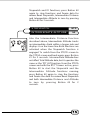
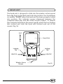
INTRODUCTION
Thank you for purchasing a Vetta V100A cycle computer. The
V100 series computers represent the latest evolution in Vetta's
computer line and are designed for cycling enthusiasts and
competitive cyclists alike. In particular, the V100A model offers a
wide range of unique features and functions such as Altitude,
Temperature, Dual Bike Memory, Intermediate Altitude and
Distance, Stopwatch readings and a Service Timer. Please take
time to familiarize yourself with all the functions of the V100A
model so you can take full advantage of its programs. And don't
forget to store this manual in a safe place for future reference!
WARNINGS & CAUTIONS
• Vetta cycle computers are sophisticated electronic instruments.
Vetta recommends that this product be installed only by a
qualified bicycle retailer. Failure to read these instructions
and/or improper installation of this device may void the
warranty. If in doubt about any aspect of the installation or
operation of this product, consult your local bicycle retailer for
clarification.
• The V100A cycle computer is a general indicator of altitude; it
is not suitable or intended for any use other than cycling.
Elevation and Percent Grade values displayed by the V100A
altimeter may be subject to slight fluctuations due to changes in
barometric pressure readings taken by the unit's pressure sensor.
Such changes, attributed primarily to variations in temperature
and weather, may affect the accuracy of this instrument.
• The head unit is water resistant and sealed to withstand wet
weather conditions. However, do not deliberately place it in
water.
• Avoid leaving the head unit exposed to extremely hot or cold
weather conditions.
• Vetta encourages you to ride safely. Wear a helmet every time
you ride, use front and rear lights at night, and always keep
your eyes on the road ahead of you.
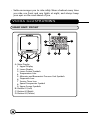
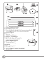
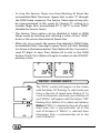
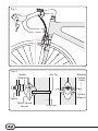
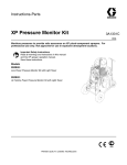
V100A ILLUSTRATIONS
HEAD UNIT: FRONT
8
1
7
A
6
5
B
D
9
4
3
C
A Main Display
1 Upper Display
2 Lower Display
3 Lower Screen Symbols
4 Temperature Icon
5 Altimeter and Barometric Pressure Unit Symbols
6 Stopwatch Icon
7 Service Timer Icon
8 Speed Comparator Symbol
9 Upper Screen Symbols
B Button #1 (Left)
C Button #2 (Right)
D Button #3 (Center)
2
P
E
N
CL
O
S
E
O
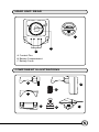
HEAD UNIT: REAR
C
R2032
C
B
A
A Contact Pins
B Battery Compartment
C Battery Cover
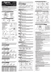
COMPONENT ILLUSTRATIONS
A
G
E
B
C
D
F
H
I
K
L
T
CE
3VO
J
LL
203
CR 2
L
LIT HIU M
M
N
A Wired Mounting Bracket
B Mounting Bracket Pad
C Riser Handle Bar Bracket Pad (You may choose B or C
according to the style of your bicycle handlebar.)
D Spoke Magnet
E Spacer
F Wired Speed Sensor
G Wireless Active Mount
H WL Wireless Speed Transmitter
I Transmitter Mounting Pad
J Wired Cadence Sensor*
K Cadence Magnet*
L CR2032 3V Battery
M Zip Ties
N Wire Securing Tape
O A23 12V Battery
P WL2X Wireless Cadence Transmitter*
*(optional)
O
P
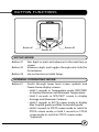
BUTTON FUNCTIONS
Button #1
Button #3
Button #2
SETUP MODE
Button #1
Button #2
Button #3
Sets digits or units and advances to the next item or
screen.
Advances digits and toggles through units. Hold for
fast advance.
Has no function in Initial Setup.
NORMAL OPERATING MODE
Button #1
Scrolls through lower level screen symbols and
Freeze Frame display screens.
• Hold 2 seconds in Temperature mode (SPD/TMP)
to display Maximum and Minimum Temperature.
• Hold 2 seconds in SPD/CAD* screen to display
Average and Maximum Cadence.
• Hold 2 seconds in ALT/% screen mode to display
Max % uphill grade and Max % downhill grade.
• Hold 2 seconds in STP/ID screen mode to switch to
STP/IA screen mode, or hold 2 seconds in STP/IA
screen mode to switch to STP/ID screen mode.
*(optional)
Button #2
Scrolls through upper level screen symbols. Press
and hold 2 seconds in any primary screen mode
to activate Freeze Frame memory. Resets RT to
zero for Service Timer.
Button #3
Starts and stops the timers and Stopwatch and is
used to reset timers, Stopwatch and other ride
data to zero. Exits Normal Operating Mode (NOM)
Setup and advances to NOM System Check and
SPD/DST screen mode.
Buttons 1&2
With RT/TT timers turned OFF, hold both buttons
simultaneously for 2 seconds in the SPD/DST
primary screen to enter NOM Setup for bicycle
functions. Hold simultaneously for 2 seconds in
the ALT/% screen to enter Pre-Ride Altimeter
Calibration Setup.
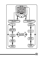
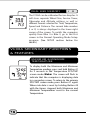
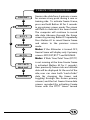
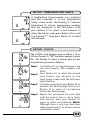
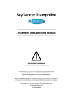
V100A SCREEN DISPLAY SEQUENCE:
BI-LEVEL MEMORY
The V100 series computers are programmed with a Bi-Level
Memory which returns to the last screen function accessed
between the upper and lower screen modes. See illustration for
this sequence and instructions on how to advance from one
screen to the next.
1
LOWER SCREEN
MODES
2
UPPER SCREEN
MODES
ALT
%
SPD
DST
1
2
TOT ALT
MAX ALT
RT
TT
1
1
CLK
ODO
1
SPD
TMP
1
BI-LEVEL
2
MEMORY
2
AVG
MAX
2
1
STP
ID/IA
SPD*
CAD
*(optional)
2
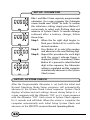
V100A PRIMARY FUNCTIONS
UPPER SCREEN MODES
SPEED
SPD
TRIP DISTANCE
DST
SPD displays the current Speed and is updated
continuously. DST displays the current Trip
Distance and automatically resets after the
maximum trip distance (999.9) is achieved.
Trip distance is displayed in the SPD/DST
screen mode and starts automatically when the
wheel rotates and TT Timer is active. Reset
DST to zero by pressing Button #3 for 2
seconds with the timers turned off in any
screen mode except STP/ID or STP/IA.
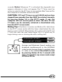
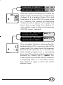
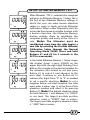
RIDE TIME
RT
TOTAL TIME
TT
Ride Time and Total Time functions are shown
simultaneously. Ride Time (RT ) measures
actual riding time and starts automatically
when the timers are set to "0:00:00" and the
wheel rotates. Total Time (TT) shows the total
elapsed trip time from start to finish. Like RT, TT
starts automatically when the wheel rotates
ONLY when the timers are set to "0:00:00", or
it can be started manually by pressing Button
#3 in the RT/TT screen mode ONLY. TT can only
be stopped manually by momentarily pressing
Button #3 in the RT/TT screen mode at the end
of a ride. To reset both RT and TT to zero, turn
the timers off and press Button #3 for at least 2
seconds. Note: Whenever TT is activated, the stopwatch icon
appears; otherwise it does not appear. The TT Timer must be
active in order for the RT Timer to accumulate Ride Time and for
the computer to calculate current ride data.
CAUTION: If RT and TT timers are not 0:00:00 and you have
stopped them manually, then they MUST be restarted manually
by pressing Button #3 in the RT/TT mode. If not, the
computer will not record speed or other ride data. RT and
TT timers can be manually activated or deactivated only
from the RT/TT screen mode.
Riding Tip: If the bike is in motion and Button #3 is held down
in the RT/TT screen mode with the timers deactivated, the ride
timers reset to 0:00:00. When Button #3 is released, both RT and
TT will start with the next wheel input. This is a good way to
begin timing a race or training ride with a rolling start.
AVERAGE SPEED
AVG
MAXIMUM SPEED
MAX
Average and Maximum Speed readings are
displayed simultaneously in the AVG/MAX
screen mode. Average Speed is updated every
0.1 miles or Km traveled. Reset both to zero
by pressing Button #3 for 2 seconds with
timers turned off in any screen mode except
STP/ID or STP/IA.
SPEED*
SPD
CADENCE*
CAD
When installed, the Cadence kit measures and
displays pedal Cadence in Revolutions Per
Minute (RPM). The SPD/CAD screen function
letters appear ONLY when the Cadence
hardware is installed and a Cadence signal
received by the head unit. After a current ride
data reset, (Button #3 for 2 seconds with the
timers off ) the function letters will disappear,
but they will come back on with the next
Cadence input. Note: RT and TT timers
MUST be activated in order for Speed and
Cadence to function.
*(optional)
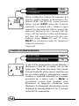
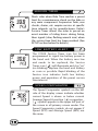
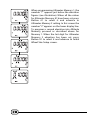
LOWER SCREEN MODES
ALTITUDE
PERCENT GRADE
ALT
%
In the ALT/% screen mode, current Altitude is
displayed in feet (ft) or meters (m) on the
upper line. The lower line shows the current
Percent Grade (%) of the road or trail that you
are on: either uphill, as indicated by a whole
number, or downhill, indicated by a number
preceded by a minus sign (-). Note: A
secondary screen that displays your
Maximum % upgrade (climbing) and
Maximum % downgrade (descending) can be
displayed by pressing Button #1 for 2 seconds
in the ALT/% screen mode.
TOTAL ALTITUDE
TOT ALT
MAXIMUM ALTITUDE
MAX ALT
Total Altitude displays the cumulative altitude
gain achieved for any given ride in feet or
meters on the upper line. The Maximum
Altitude or highest elevation attained during a
ride is displayed on the lower line. Note: TOT
ALT does not include descents. Both Total and
Maximum Altitude readings can be cleared by
pressing Button #3 for 2 seconds with the
timers turned off in any primary screen except
STP/ID or STP/IA.
CAUTION: Whenever you clear ride data
between rides or during a ride, you must
recalibrate your Altimeter before you start
riding again. Otherwise the Altimeter will not
function.
Riding Tip: Before you clear ride data (especially
during a ride), always check your "current"
altitude reading so you will know your present
elevation when you recalibrate your altimeter. To
recalibrate properly and most accurately, you
need to know either your exact current altitude
or the current barometric pressure at sea level
for your locale.
CLOCK
CLK
ODOMETER
ODO
The time is displayed in the CLK/ODO screen
mode and features a user selectable 12 or 24
hour format. The Odometer displays cumu-lative
distance until an All Clear Total Reset is
performed, the battery is changed*, or the ride
distance exceeds the maximum limit, after which
the Odometer will automatically reset to zero.
*Note: Odometer reading can be reinstalled
by user after a battery change.
SPEED
SPD
TEMPERATURE
TMP
Current Temperature is displayed in the lower
screen digits and updated once per minute.
The thermometer icon illuminates when the
Temperature display is active, and the right
digit displays the scale selected in degrees
Celsius "C" or degrees Fahrenheit "F". Below
zero readings are indicated by a minus sign (-).
Note: A secondary screen displays Maximum
and Minimum Temperatures on the upper
and lower lines respectively. Press and hold
Button #1 for 2 seconds to access the
Max/Min TMP screen. Press Button #1 again to
return to the SPD/TMP primary screen.
Note: The temperature reading can
sometimes vary due to the computer head
unit being heated by direct sunlight; which can
heat the case hotter than the actual air
temperature.
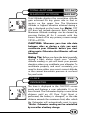
STOPWATCH
INTERMEDIATE DISTANCE
STP
ID
The independent Stopwatch (STP) is operated
by Button #3 in the STP/ID screen mode. STP
operates in conjunction with the RT/TT
timers (
icon must be visible) and can be
started or stopped by pressing Button #3.
The Intermediate Distance function tracks
an intermediate distance within a longer ride.
ID does not affect overall Trip Distance or
current ride data, but it operates the same as
the DST function. From the STP/ID screen mode
with timers active, press Button #3 to start
Stopwatch and ID functions; press Button #3
again to stop functions and freeze data for
review. Reset Stopwatch, Intermediate Distance
and Intermediate Altitude to zero by pressing
Button #3 for 2 seconds.
STOPWATCH
INTERMEDIATE ALTITUDE
STP
IA
Like the Intermediate Distance function
described above, Intermediate Altitude tracks
an intermediate climb within a longer ride and
displays it on the lower line. Both functions are
activated when the Stopwatch function is
engaged. To switch from the STP/ID screen to
the STP/IA screen and back again, press Button
#1 for 2 seconds. Intermediate Altitude does
not affect Total Altitude data, but it operates the
same as the TOT ALT function. From the STP/IA
screen and with the RT/TT timers active, press
Button #3 to start the Stopwatch and the
Intermediate Altitude functions running;
press Button #3 again to stop the functions
and freeze the data for review. Reset Stopwatch
and both Intermediate Distance and Altitude
to zero by pressing Button #3 for 2
seconds.
DUAL BIKE MEMORY
I
II
The V100A can be calibrated for two bicycles. It
will store separate Wheel Size, Service Timer,
Odometer and Altitude settings, as well as
different formats selected for Time, Temperature,
Speed and Distance. The current bike number
(I or II) is always displayed in the lower right
corner of the screen. To switch the computer
quickly from Bike I to Bike II, go to the first
screen in the Normal Operating Mode Setup
program. (See SETUP section below for
details.)
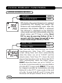
V100A SECONDARY FUNCTIONS
& FEATURES
MAXIMUM & MINIMUM
TEMPERATURE
To display both the Maximum and Minimum
Temperature readings, press and hold Button #1
for 2 seconds in the Temperature SPD/TMP
screen mode. Note: The screen will flash to
indicate that the computer is displaying data
in a secondary screen. To return to the primary
SPD/TMP screen mode, press Button #1 again.
When ride data is reset by holding Button #3
with the timers stopped, both Maximum and
Minimum Temperatures reset to the current
Temperature.
AVERAGE CADENCE*
AVG CAD
MAXIMUM CADENCE* MAX CAD
When the Cadence mounting kit is installed, the
V100A displays both Average and Maximum
Cadence in a secondary screen. Press and
hold Button #1 in the SPD/CAD screen mode
for 2 seconds. The Average and Maximum
Cadence functions appear on the upper and
lower lines respectively. Press Button #1
once again in order to return to the primary
SPD/CAD screen. *(optional)
MAXIMUM PERCENT
GRADE-CLIMBING
MAX %
MAXIMUM PERCENT
GRADE-DESCENDING
MAX % (
)
These secondary functions can be reached by
holding Button #1 for 2 seconds in the ALT/%
screen mode. This screen shows the Maximum
Percent Grade attained on a current ride
while climbing (upper line) or descending
(lower line). The percent grade for descents is
preceded by a minus sign (--). Note: This
screen will flash to indicate that the computer
is displaying data in a secondary screen.
Press Button #1 again to exit to the ALT/%
primary screen.
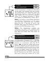
SERVICE TIMER
Alerts rider when Ride Time reaches a preset
limit for a maintenance check on the bike or
any main component. Suspension forks, rear
shocks, chains, etc. require service at specific
time intervals set by manufacturers. Vetta's
Service Timer allows the rider to preset an
exact number of riding hours during Setup,
then signals (slow, flashing wrench icon) when
the service time limit has been reached. (See
SETUP section below for details.)
LOW BATTERY ALERT
The V100A Service Timer icon has been
programmed to signal low battery power in
the head unit. When the battery runs low
and needs to be replaced, the Service
Timer icon (
) will illuminate and stay "on"
(no blinking). Replace the head unit battery
as soon as possible. Rapid blinking of the
Service icon indicates both low battery
power and expiration of the preset service
time interval.
SPEED COMPARATOR
The Speed Comparator symbols on the left
side of the display screen indicate whether
current Speed is above or below current
Average Speed. A positive ( ) or negative
( ) symbol appears in the upper left part of
the screen in all primary screen modes. The
Speed Comparator symbols do not appear if
Speed (SPD) and Average Speed (AVG) are
the same.
FREEZE FRAME MEMORY
SPD/DST
2
SPD/DST
1
RT/TT
1
1
AVG/MAX
1
Freezes ride data from 5 primary screens
for review at any point during a race or
training ride. To activate Freeze Frame,
press and hold Button #2 for 2 seconds
in any primary screen mode. The screen
will flash to indicate it has been frozen.
The computer will continue to record
ride data. Advance through the frozen
screens by pressing Button #1 repeatedly.
Press Button #2 to cancel Freeze Frame
and return to the previous screen
mode.
ALT/%
Note: If the Altimeter is turned OFF,
Freeze Frame will display only 3 primary
screens: SPD/DST, RT/TT and AVG/MAX.
1
Note: If Ride Time/Total Time (RT/TT)
TOT ALT/
MAX ALT
2
SPD/DST
is not running at the time Freeze Frame
is activated (Button #2 for 2 seconds),
then previously frozen ride and altitude
data will be displayed. At the end of the
ride, user can view both "end-of-ride"
data (by stopping the timers and
toggling through the frozen primary
screens) and the last Freeze Frame data
screens recorded (by activating Freeze
Frame with the RT/TT timers turned
AUTO START
If the RT/TT ride timers read zero (0:00:00), the Vetta V100A
computer automatically starts as soon as it receives input from the
wheel. The RT and TT timers are activated and other ride data
begins to accumulate (SPD, DST, AVG & MAX SPD, CAD*, AVG &
MAX CAD*, ODO, TOT ALT and %).
Note: Any time the timers are stopped manually and they are
not cleared, RT and TT must be restarted manually by pushing
Button #3 in the RT/TT screen mode.
*(optional)
SLEEP MODE
To conserve battery life, the V100A computer is
programmed to enter a Sleep Mode after
receiving no input from buttons, wheel motion
or cadence for 5 minutes. In this mode the
V100A screen displays only the time of day. The
computer exits Sleep Mode automatically, in
the wired version only, when it receives
input from buttons or wheel/crank motion
and returns to the screen last displayed. In
the wireless version the computer will "wake
up" only when one of the buttons is pushed.
The Altitude sensor will "read" new altitude as
soon as the computer exits from Sleep Mode.
Clock, Stopwatch and Total Time (for the ride)
continue to run during the Sleep Mode.
RIDE DATA RESET
To reset current ride, Freeze Frame and Altitude data to zero (DST,
RT, TT, AVG & MAX SPD, AVG & MAX CAD*, TOT & MAX ALT, MAX %
& MAX % (-), MAX & MIN TMP, STP, ID and IA), make sure the
timers (RT/TT) are turned OFF and press Button #3 for 2 seconds
in any primary screen mode except STP/ID or STP/IA.
WARNING: The Altimeter must be re-calibrated after any
ride data reset and before the next ride. See the section on
Altimeter Calibration Setup below. *(optional)
ALL CLEAR TOTAL RESET
All settings entered in Initial Setup, as well as all accumulated
ride data, can be cleared by performing an All Clear Total Reset.
To clear the computer, press all three buttons simultaneously and
hold for 5 seconds in any screen mode. When the computer is
cleared, the master screen will appear and show all LCD
segments for 3 seconds. The computer will then automatically
enter Initial Setup mode to be reprogrammed.
Note: Both Initial and Normal Operating Mode Setup utilize the
same sequence of Setup screens. Initial Setup is activated after a
battery installation or change, or after an "All Clear Total Reset"
has been performed. All units and values must be (re)entered
during Initial Setup. The Normal Operation Mode Setup program
allows the user to change or correct any value or units easily. To
access NOM Setup, press and hold Buttons #1 and #2 for 2
seconds in the SPD/DST screen mode. Scroll to the value you
wish to change quickly by pressing Button #1 successively.
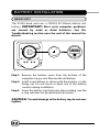
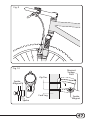
BATTERY INSTALLATION
HEAD UNIT
The V100A head unit uses a CR2032 3V lithium button cell
battery. IMPORTANT: Most cycle computer problems
are caused by weak or dead batteries. See the
Troubleshooting section near the end of this manual for
details.
O
E
N
CL
O
S
EL
L
P
C
3VO
LT
L
20 32
E
CR
ITHIUM
C
R2032
Step 1: Remove the battery cover from the bottom of the
computer using a coin. Remove the old battery.
Step 2: Install a new battery as shown with the positive (+) side
facing out. Do not touch or bend any of the battery
contacts during installation.
Step 3: Screw the battery cap firmly into place making sure the
o-ring seal does not get pinched or distorted.
CAUTION: To avoid damage to the battery cap, do not over
tighten.
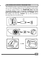
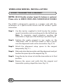
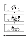
WL WIRELESS SPEED TRANSMITTER
The V100A WL wireless speed transmitter (signal from the wheel)
uses an A23 12V battery. Remove cap, install battery with positive
(+) side up, replace battery cap. CAUTION: Make sure the
transmitter battery cap is properly installed to insure
good signal transmission. Be sure to align the "CLOSED" dot on
the battery cap with the "CLOSED" dot on the transmitter
housing when you reinstall the cap.
A23
12V
CLO
S
12
V
3
E
CLO
SE
N
E
P
CLO
SE
CLO
S
N
E
P
12
V
2
A
OPEN
O
N
2
A
CLOSE
O
OP
E
3
N
E
P
E
N
CLO
SE
OP
E
A2
3 12V
O
SETUP MODE & PROGRAMMING
INTRODUCTION
After battery installation, the master screen will appear briefly
and the computer will automatically go into the Initial Setup
program mode. Note: To enter Setup when in the Normal
Operating Mode (NOM), go to the SPD/DST screen mode and
press Buttons #1 and #2 simultaneously for 2 seconds with
the RT/TT timers off. Exit NOM Setup mode by pressing Button
#3.
Both the Initial and NOM Setup modes allow the rider to select
operational units and values for the computer function displays.
All the steps in the Initial Setup mode have been pre-programmed. If
an entry error is made, complete the Initial Setup program and
then re-enter Setup from the Normal Operating Mode as
described above to revise the setting.
In both Initial and Normal Operating Mode Setup, press Button #2 to
toggle between possible unit settings, such as M/hr and KM/hr. Press
Button #1 to select a unit or value and advance to the next digit
or screen. Press Button #3 at any time to exit NOM Setup and go
directly to System Check. Note: If no buttons are pressed for
approximately 5 minutes during Setup, the computer will
automatically enter Sleep Mode and then return to the screen
last displayed when reactivated.
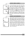
SETUP: BIKE I & BIKE II
In the Initial Setup mode, after the master
screen stops flashing, the screen displays the
letters "bic no". The default setting is Bike "I".
To toggle between Bike I and Bike II settings,
press Button #2. With Bike "I" icon flashing,
press Button #1 to select it and advance to the
next Setup screen. Note: When programming
a second bike in Initial Setup, scroll to "II",
select it, and advance as instructed above.
The V100A computer will retain the values
and settings entered for Bike II independently
of Bike I.
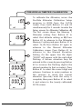
SETUP: ALTITUDE UNITS
After the bike number has been selected, the
Initial Setup program automatically advances
to the Altitude Units Setup screen. The default
setting for Altitude units is feet (ft). To confirm
you want to see altitude readings in feet, press
Button #1 to select that value and advance to
the next Setup screen. To choose meters (m)
instead as the unit of altitude you wish to
use, press Button #2 to toggle to that value
("m" will flash), then press Button #1 to
select it and advance.
SETUP: ALTIMETER ON/OFF
This Setup screen allows you to turn the
Altimeter function "ON" or "OFF" as you
choose. The default setting for the Altimeter
is "ON". Press Button #1 to select Altimeter
"ON" and advance to the next screen. Or, if
you don't want to activate the Altimeter
function, press Button #2 to toggle to the
"OFF" setting and press Button #1 to select it
and advance. Note: If the user selects
Altimeter "OFF", the Initial Setup program will
skip the Altimeter Memory programming
steps below and automatically advance to
the Wheel Size Setup screen.
SETUP: ALTIMETER MEMORY 1 & 2
After Altimeter "ON" is selected, the computer
advances to Altimeter Memory 1 Setup. This is
the first of two Altimeter Memory settings in
which the user can enter known elevation
values to serve as quick, pre-ride Altimeter
calibrations. When a rider frequently starts his
or her ride from home or another location with
a known elevation, the Altimeter Memory
feature enables them to recalibrate the
computer quickly and easily at the start of a
ride. Note: The Altimeter must be
recalibrated every time the rider begins a
new ride by accessing the Pre-Ride Altimeter
Calibration Setup through the Normal
Operating Mode (NOM) (Press and hold
Buttons #1 and #2 for 2 seconds in the
ALT/% screen mode).
In the Initial Altimeter Memory 1 Setup screen,
the display shows 5 zeros (00000) on the
upper line with the right digit flashing. Press
Button #2 to toggle to the desired number for
the elevation you intend to set and press
Button #1 to select it and advance to the
next digit. Continue to use Button #2 to
advance the digits from "0" to "9" as needed
to set a specific elevation. Note: To set a
negative, below sea level elevation, the rider
must enter a minus sign (-) at the front of the
elevation reading and select it by pressing
Button #1. Note: The default elevation value
for both Memory 1 and Memory 2 is "00000"
or sea level. The largest possible positive
elevation value is "99999" feet or meters.
The largest possible negative elevation value
is "-9999" feet or meters.
When programming Altimeter Memory 1, the
number "1" appears just below the elevation
figures (see illustration). When all the values
for Altimeter Memory #1 have been set, press
Button #1 to select it and advance to
Altimeter Memory 2 setting. In this screen the
number "2" appears on the lower display line.
To program a second elevation into Altitude
Memory, proceed as described above for
Memory 1. When the last digit for Altimeter
Memory 2 elevation has been set, press
Button #1 to select it and advance to Initial
Wheel Size Setup screen.
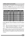
WHEEL SIZE CALCULATION
The circumference of the wheel is measured and entered in
millimeters. Bike I and II wheel sizes are set independently, and
both default to 2074mm (700c x 20 or 26 x 2.0). The following
chart lists the circumference measurements for the most common
wheel sizes. To use this chart, find your tire size and record the
corresponding circumference measurement.
TIRE SIZE
CIRC
TIRE SIZE
CIRC
700c x 38mm
700c x 35mm
700c x 32mm
700c x 30mm
700c x 28mm
700c x 25mm
700c x 23mm
700c x 20mm
700c Tubular
650c x 23mm
650c x 20mm
2180
2168
2155
2145
2136
2124
2105
2074
2130
1990
1945
27" x 1-1/4"
27" x 1-1/8"
26" x 2.25"
26" x 2.1"
26" x 2.0"
26" x 1.9"
26" x 1.75"
26" x 1.5"
26" x 1.25"
26" x 1.0"
20" x 1-1/4"
2161
2155
2115
2095
2074
2055
2035
1985
1953
1913
1618
If your wheel size is not on the chart, or if you want a more
precise calibration, wheel circumference may be calculated
as follows:
Step 1: Measure the distance from the center of the front wheel
axle to the ground in millimeters. (1 inch = 25.4mm)
Step 2: Multiply this distance by 6.2832 (2±) and enter the
result as the wheel size setting into the computer.
OR Mark the tire and a spot on the floor. Roll the wheel forward
one complete revolution until the tire mark touches the floor
again and mark that spot. Measure the distance between the
marks on the floor in millimeters and enter the result into the
computer.
SETUP: WHEEL CIRCUMFERENCE
After Altimeter Memory 1 & 2 values have
been selected and the display advances to
the Wheel Size Setup screen, the letters "circ"
appear on the lower level and the default
numbers 2074 appear on the upper level
with the right digit "4" flashing.
Step 1: To enter a specific wheel size, press
Button #2 to advance the flashing
digit to the desired number.
Step 2: When the correct number is reached,
select it by pressing Button #1. The
next digit to the left will start
Step 3: flashing.
Press Button #2 to advance the
flashing digit to the next desired
number in the sequence and press
Button #1 once again to select it
and advance. Repeat this procedure
until all four digits are selected. The
computer
will
automatically
advance to the Service Timer Setup
screen.
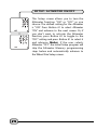
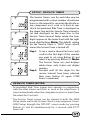
SETUP: SERVICE TIMER
The Service Timers, one for each bike, may be
programmed with a select number of ride time
hours as the interval for servicing the bicycle or
any component on it, such as a front or rear
shock. Accumulated Ride Time is displayed on
the upper line and the Service Time interval is
set and displayed on the lower line. In the
Service Timer Interval Setup mode, the hour
digits appear on the lower level with the right
hand digit flashing. Note: The default setting
for the Service Timer is "0000" hours, which
means the Service Timer is turned off.
Step 1: To set a service interval (in hours only)
scroll to the first digit of the number
you want to set using Button #2 and
select it by pressing Button #1. Note:
The Service Timer sets and displays
whole hours only. It does not display
minutes.
Step 2: Proceed until all the digits for the
service interval have been selected,
then press Button #1 again. (1999
hours = maximum)
SERVICE TIMER NOTES
• Accumulated Ride Time (upper line) operates in conjunction
with the other timers and starts as soon as the wheel turns. It
stops automatically when the computer receives no input from
the wheel for 3 seconds.
• The Service Timer screen can be viewed in both the NOM
Setup mode and in the System Check screen sequence. Access
NOM Setup through the SPD/DST screen mode by pressing
Buttons #1 and #2 simultaneously for 2 seconds with RT/TT
timers off.
• To stop the Service Timer icon from flashing: A) Reset the
accumulated Ride Time hours (upper line) to zero "0" through
the NOM Setup sequence. The Service Timer interval may also
be reprogrammed at this point. B) Change TT setting to a
number larger than accumulated RT. C) Set TT to zero "0000"
(disable the Service Timer).
• The Service Timer option can be disabled in Initial or NOM
Setup mode by entering and selecting a value of zero "0000"
hours as the service time interval (lower line).
• After user sets or resets the service time interval in NOM Setup,
accumulated Ride Time digits (upper level) will start blinking
(as shown in illustration below). Press Button #2 for 2 seconds to
reset RT digits to zero. Press Button #3 to exit to the NOM
System Check. Press Button #3 again to return to the SPD/DST
primary screen.
SETUP: SPEED UNITS
The "M/hr" symbol will appear on the screen
with the letter "M" flashing. To select miles per
hour as the unit of speed, press Button #1. To
scroll to kilometers per hour, press Button #2
and "KM/hr" will appear with the letters "KM"
flashing. Press Button #1 to select and advance.
Note: If "M/hr" is selected as the unit of speed,
then miles (m) is automatically set as the
unit of distance. If "KM/hr" is selected, then
kilometers (Km) is automatically set as the
unit of distance.
SETUP: TEMPERATURE UNITS
A highlighted thermometer icon indicates
that the computer is in the Temperature
Setup screen mode. The flashing "F" indicates
Fahrenheit. To choose temperature readings
that are displayed in the Fahrenheit scale,
press Button #1 to select it and advance. To
select the Celsius scale, press Button #2 to scroll
to a flashing "C". Then press Button #1 to select
and advance.
SETUP: CLOCK
The V100A clock displays time in either a 12 or
24 hour format. A "PM" indicator appears only in
the 12hr format. To select a format and set the
current time, proceed as follows:
Step 1: Use Button #2 to toggle between the
two time formats (the numbers will
flash).
Step 2: Press Button #1 to select the desired
time format and advance to the
Clock Setup screen with the left hours
digits flashing.
Step 3: To set the current time, press Button #2 to
advance the flashing digit, then press
Button #1 to select it and advance
to the next flashing digit.
Step 4: Repeat this procedure for each digit
until the correct time is set in hours
and minutes, then press Button #1
again to select and advance. Note:
Although there is only one clock time,
either time format-12 or 24 hour-can be
set for bikes I and II.
SETUP: ODOMETER
Bike I and Bike II have separate, programmable
odometers. On a new computer the Odometer
screen should read "00000" for both. To confirm
this initial zero setting, simply press Button #1
successively to select each flashing digit and
advance to System Check. To reenter mileage
achieved after a battery change, follow
these steps:
Step 1: When the far right digit begins to
flash, press Button #2 to scroll to the
desired number.
Step 2: Press Button #1 to select this number
and advance to the next flashing digit.
Step 3: Repeat this procedure for each digit
until the correct mileage figure is
displayed (99999 = maximum). When
Button #1 is pressed to select the final
digit in the sequence, the Odometer
setting is completed and the computer
automatically advances to the System
Check screen.
SETUP: SYSTEM CHECK
After the Programmable Odometer is set, both the Initial and
Normal Operating Mode Setup programs will automatically
advance to the System Check screen sequence. System Check
displays all value and unit settings chosen during Setup in a 6
screen sequence with the Altimeter "ON", or a 5 screen sequence
with the Altimeter "OFF". Each screen in System Check appears
for 5 seconds and will blink. When the review is complete, the
computer automatically exits Initial Setup System Check and
advances to the SPD/DST screen in Normal Operating Mode.
To change any values or correct any unit errors made during
Initial Setup, you must re-enter the Setup program in NOM by
pressing Buttons #1 and #2 simultaneously for 2 seconds in the
SPD/DST screen mode with the RT/TT timers deactivated.
Note: System Check is activated in two ways: A) Automatically
at the end of either Initial or NOM Setup and B) By pressing
Button #3 at any time during NOM Setup. To exit System Check
manually in NOM Setup, press Button #3 to return to the SPD/DST
primary screen mode.
PRE-RIDE ALTIMETER CALIBRATION
SETUP
INTRODUCTION
Before any new ride, the V100A Altimeter must be recalibrated so
that it "knows" the correct starting elevation. Because elevation is
calculated via barometric pressure, changes in barometric
pressure detected by the sensor change the elevation displayed
on the ALT/% screen. Barometric pressure falls as elevation
increases and rises as elevation decreases.
To ensure the accuracy of altitude data, recalibration of the
V100A Altimeter is accomplished in two ways: A) By entering a
known elevation for a current location or B) By entering the
current, local barometric pressure at sea level for that moment in
time. A known elevation reading can be A) Recalled from either of
2 elevations stored in Altimeter Memory 1 and 2, or B) Entered
manually, based on a current location in feet or meters. Or, the
user may find out the current local barometric pressure reading
from a local airport, weather service bureau or online from an
internet source such as www.noaa.com or yahoo weather at
www.yahoo.com.
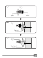
PRE-RIDE ALTIMETER CALIBRATION
A
B
C
To calibrate the Altimeter, access the
Pre-Ride Altimeter Calibration Setup
program in NOM from the ALT/%
screen. Press both Buttons #1 and #2
simultaneously for 2 seconds to enter the
Setup screens for Altimeter Calibration. A)
The first screen shows the Memory 1
Altimeter setting. Press Button #1 to
select that altitude setting, or B) Press
Button #2 to advance to the Altimeter
Memory 2 setting and press Button #1 to
select. Or, C) Press Button #2 again to
advance to the Manual Altimeter
Calibration screen. Press Button #1 to
advance to the Manual Elevation
Setting. On the upper line the digits
"00000" will appear with the right digit
flashing. A known elevation may be
entered in this screen by pressing Button
#2 to increase the flashing digit to the
desired number (in feet or meters). Press
Button #1 to select the correct digit and
advance. Continue to enter numbers in
this manner to reach the current
elevation (pre-ride) until the entry is
complete, then press Button #1 to select
it and return to the (newly calibrated)
ALT/% screen.
BAROMETRIC CALIBRATION
The V100A Altimeter may also be calibrated
by entering the current, local, barometric
pressure at sea level either in Inches of
Mercury (inHg) or in Millibars (mbar). To
access the barometric entry screens, press
Button #2 to bypass the Manual Altimeter
Elevation input screen (See point C above).
The letters "inHg" will then appear and start
to flash. If you wish to enter barometric
pressure in Inches of Mercury, press Button #1 to
select that unit of pressure and advance to the
inHg calibration screen. Use Button #2 to
advance the digits to the correct number and
press Button #1 to select and advance. When
all the digits for the inHg units have been
entered, press Button #1 to select that setting
and advance to the ALT/% screen.
If, however, you wish to enter barometric
pressure in Millibars (mbar), press Button #2
while "inHg" is flashing to scroll to the Millibars
calibration screen with the letters "mbar"
flashing. To enter the current pressure in
Millibars, press Button #1 to select that setting
and enter the digits as instructed above.
Note: Once you have set a barometric pressure
and selected it by pressing Button #1, the
computer will automatically convert the
pressure reading to an elevation (in feet or
meters) and exit Altimeter Calibration Setup
to the ALT/% screen.
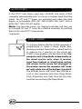
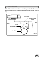
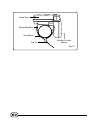
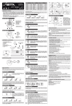
PERCENT GRADE
VETTA uses a barometric sensor to gauge the (noise) changes in
the air pressure which does not update constantly; this is why
sometimes you may get varying readings due to weather
changes, fast ascents and descents or not enough change in
altitude i.e. small rolling hills.
These are some of the other guidelines you can use to improve
the accuracy of readings.
• It will take at least a 20-30m distance (depending on the
pressure sensor) before it starts to output a gradient reading
even for steep slope (say over 10%).
•It will output a gradient reading of a slope which vertical
displacement is larger than 3-5m. i.e. it will display zero
gradient if the vertical displacement of the short slope is less
than 3m in height.
• For the same reason as above, the V100A may display zero or
higher gradients; if the user climbs a short slope followed by
descending another short slope.
• If you are looking for what we call a real-time altimeter, the most
accurate way is GPS. Otherwise most altimeters use a very
sensitive pressure sensor that measures the changes in the air
pressure.
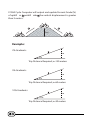
V100A Cycle Computer will output and update Percent Grade (%)
of uphill or downhill
whenB the vertical displacement is greater
A
than 3 meters.
A
B
3m
Example:
2% Gradients:
x
3m
2%
Trip Distance Required, x=150 meters
5% Gradients:
x
3m
5%
Trip Distance Required, x=60 meters
10% Gradients:
x
3m
10%
Trip Distance Required, x=30 meters
INSTALLATION
WIRED MODEL INSTALLATION
SPEED SENSOR & MAGNET
NOTE: Wired cadence is optional. Please refer to WIRED
SPEED AND CADENCE/WL2X DOUBLE WIRELESS SPEED AND
CADENCE MANUAL for installation.
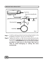
Step 1: Use the zip-tie supplied to hold loosely the wired speed
sensor and mounting pad to the inside of either fork leg.
We recommend mounting it as high up on the fork leg
as possible to protect it from being hit by rocks,
branches or other objects while riding. (Fig. 1)
Step 2: Tighten the spoke magnet to any spoke on the "sensor
side" of the front wheel so that it passes over the
alignment mark on the sensor. (Fig. 1, 2)
Step 3: Attach the alignment setup spacer to the magnet
temporarily. (Fig. 3)
Step 4: Slide and rotate the sensor until the alignment mark just
touches the spacer tip on the magnet. (Fig. 4)
Step 5: Route the sensor wire up the fork blade and secure it
with the tape. Wrap excess wire around the front brake
cable housing, leaving enough slack to attach the
mounting bracket easily to the handlebar and allow for
movement of the bar and stem. CAUTION: When
installing the speed sensor on a suspension fork,
make sure that the fork is fully extended to ensure
there is enough wire to reach the mounting bracket
properly. Excess sensor wire should be taped down
or wrapped around the brake cable housing for
safety.
Step 6: Snug the zip tie down to hold the sensor in its final
position.
Step 7: Remove the spacer and verify that the magnet and
sensor spacing stayed the same. (Fig. 5)
Note: Do not use a zip-tie tightening tool or a third hand tool
when doing the final tensioning of the zip-ties. This can tear and
damage the sensor or transmitter.
Fig. 1
Fig. 2
Spoke
Magnet
Zip Tie
Spoke
Magnet
Spoke
Wired Speed
Sensor
Magnet
Sweep
Path
Fork Leg
Fig. 3
Spoke
Magnet
Spoke
Fig. 4
Spacer
Spacer
Tip
Alignment
Mark
Fig. 5
Spoke
Magnet
Wired Speed
Sensor
MOUNTING BRACKET
Head Unit
Wired Mounting Bracket
Zip Tie
Mounting Pad
Handlebar
Fig. 6
Step 1: Install mounting pad and wired mounting bracket to the
handlebar using the 2 zip ties provided. (Fig. 6)
Step 2: Tighten the zip ties so that the mounting bracket holds
its position on the bars yet can be easily adjusted. (Fig. 7)
Trim excess. CAUTION: Do not use zip ties but tapes
provided to hold wires to the frame, fork, bars or
stem to avoid damaging or cutting the wires
accidentally.
Head Unit
Wired
Mounting Bracket
Mounting Pad
Zip Tie
Handlebar
Fig. 7
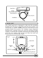
HEAD UNIT
The V100A head unit is designed to slide into the mounting
bracket from the front to the back and lock into position. You
should hear an audible "CLICK" when the head unit has been
properly locked into position. This indicates proper alignment
between the computer head pins and the mounting bracket
contacts. To remove the computer head from the bracket, gently
pinch the two locking tabs inward and slide the head unit
forward and out of the bracket. (Fig. 8)
Fig. 8
OUT
Head Unit
IN
Locking
Tab
UNLOCK
Locking
Tab
UNLOCK
Wired Mounting Bracket
WIRELESS MODEL INSTALLATION
SPEED TRANSMITTER & MAGNET
NOTE: WL2X Double wireless Speed & Cadence is optional.
Please refer to WIRED SPEED AND CADENCE/WL2X DOUBLE
The V100A is designed to operate as a wireless unit with the
installation of a special active mount and WL wireless speed
transmitter.
Step 1: Use the zip-ties supplied to hold loosely the wireless
speed transmitter and mounting pad to the left fork leg.
Note: To maximize signal reception, position the
transmitter as high up on the fork leg as possible. (Fig. 9)
Step 2: Tighten the spoke magnet to any spoke on the
"transmitter side" of the front wheel so that it passes
over the alignment mark on the transmitter. (Fig. 9, 10)
Step 3: Attach the alignment setup spacer to the magnet
temporarily. (Fig. 11 )
Step 4: Slide and rotate the transmitter until the alignment mark just
touches the spacer tip on the magnet. (Fig. 12)
Step 5: Snug the zip ties down to hold the transmitter in its final
position.
Step 6: Remove the spacer and verify that the magnet and
transmitter spacing stayed the same. (Fig. 13)
Fig. 9
Fig. 10
Magnet
Sweep
Path
Zip Ties
Spoke
Magnet
UP
A23
OPEN
O
P
EN
CLOSE
CLO
SE
Fork Leg
Spoke
Spoke
Magnet
Fig. 11
Spoke
Magnet
Spacer
Spoke
Fig. 12
N
PE
OPEN
O
Spacer
Tip
CLOSE
CLO
SE
Alignment
Mark
A23
Fig. 13
N
PE
OPEN
O
Wireless Speed
Transmitter
CLOSE
CLO
SE
Spoke Magnet
A23
ACTIVE MOUNT
Attach the active mount and mounting pad to the handlebar.
Adjust its position to your liking and tighten the zip ties. (Fig. 14,
15)
Head Unit
Wireless Active
Mount
Zip Tie
Mounting Pad
Handlebar
Fig. 14
Head Unit
Mounting Pad
Handlebar
Zip Tie
Wireless Active
Mount
Fig. 15
HEAD UNIT
The head unit is designed to slide into the wireless active mount
from the front to the back and lock into position. You should hear
an audible “CLICK” when the head unit has been properly locked
into position. This indicates proper alignment between the
computer head pins and the active mount contacts. To remove
the computer head from the mount, gently pinch the two locking
tabs inward and slide the head unit forward and out of the
mount. (Fig. 16)
OUT
Head Unit
IN
Locking
Tab
UNLOCK
Wireless Active
Mount
Locking
Tab
UNLOCK
Fig. 16
INSTALLATION TESTS
Once installation is complete, the computer should be tested to
make sure it is working properly.
Step 1: Advance the computer to the SPD/DST screen mode
using Button #2.
Step 2: Pick up the front of the bicycle and spin the front wheel.
The computer should display a speed reading within 2-3
seconds.
If there is no speed reading, make sure the timers (RT/TT) are
running, check the alignment and spacing between the
magnet and sensor or transmitter and make sure that the
head unit is completely snapped into position. If these checks do
not solve the problem, talk to an Authorized Vetta Retailer or
connect to www.vetta.com.
IMPORTANT: Following the installation tests above, make
sure that the spoke magnet locking screw and all zip ties are
properly tightened.
Tips: Rotating the angle of the transmitters or the handlebar
receiver (slightly), can sometimes improve the signals being sent
and received. Some bicycles have unusual frame tubes and angles,
so by adjusting the components, can aid in trouble shooting by
aligning the misdirected signals.
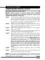
TROUBLESHOOTING
PROBLEM/ITEMS TO CHECK/SOLUTION
• Current speed reading is erratic or does not appear.
Check the alignment of the spoke magnet and sensor, and the
distance between the two components. Realign the magnet
and sensor with the spacer. Check to be sure RT and TT are
activated.
• Current speed reading is erratic or does not appear.
Inspect the wiring for any breaks or kinks. Replace the
mounting bracket and sensor as needed.
• Incorrect data appears on screen during operation.
Accuracy of the Setup data may be a problem (wheel
circumference setting, bike #, etc.). Review data in System Check
mode and revise as needed.
• Altimeter reading is "wrong".
Altimeter needs to be re-calibrated. See sections in Setup for
instructions on how to recalibrate the Altimeter through
elevation or barometric pressure settings. IMPORTANT: The
Altimeter must be re-calibrated before every ride.
• Data display is extremely slow.
Computer LCD does not operate well in extremely low
temperatures. Operating range is: 0ºC to 50ºC or 32ºF to 122ºF.
Return computer to warmer climate.
• Screen is dark and display characters look "strange".
Computer screens are adversely affected if left in direct sunlight
for extended periods of time. Move the computer into the shade
until the screen recovers. No effect on data.
• Screen reading is weak or fading.
Symptom of interference or a weak battery.
Replace the battery.
• Screen readings are erratic and read too high or too low.
Symptom of a weak battery.
Replace the battery.
• Screen "frozen", no response to buttons.
Symptom of a weak battery.
Replace the battery.
• No display whatsoever.
Battery is completely dead, or not installed.
Replace or install the battery.
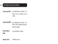
TECHNICAL SPECIFICATIONS
Current Speed (SPD)
0.0~120.0 KM/hr; 0.0~75.0 Mi/hr; +/-0.1
KM/hr or Mi/hr. Updated once per
second.
Average Speed (AVG)
0.0~120.0 KM/hr; 0.0~75.0 Mi/hr; +/-0.1
KM/hr or Mi/hr. Updated once every 0.1
Miles or Km traveled.
Maximum Speed
(MAX)
Limit: 120.0 KM/hr; 75.0 Mi/hr.
Odometer (ODO)
0~99999 km or miles.
Trip Distance (DST)
0.0~999.9 km or miles; +/- 0.1 km or mi.
Temperature (TMP)
Range: 0ºC~49ºC or 32ºF~120ºF; +/- 1ºC
or ºF.
Altimeter (ALT)
Range: -660 to 16,500 feet or -200 to
5000 meters; +/- 10 feet or 3 meters.
Barometer
Range: 11.8 to 32 inHg or 400 to 1100
mbar.
Clock (CLK)
12 or 24 hour format, hours and
minutes displayed.
Service Timer
Limit: 1~1999 hrs. max; +/-1 hr.
Stopwatch (STP)
Limit: 9:59:59 (10 hrs.); +/-1.0
seconds.
Intermediate Distance (ID)
Range: 999.9 km or miles.
Intermediate Altitude (IA)
5000 meter minus the current
altitude when activate the IA
feature
Ride/Total Time (RT/TT)
Limit: 9:59:59 (10 hours) displayed in
hr/min/sec. After 9:59:59, display
restarts at "0:00:00".
Cadence (RPM) (optional)
Range: 15~255 RPM; +/-1 RPM.
Power Supply
Head Unit: CR2032 3 volt battery.
WL Wireless Speed Transmitter:
A23 12 volt battery.
Battery Life
Head Unit:
Wired: 260 days
Wireless: 150 days
WL Wireless Speed Transmitter:
180 days
(1 hour training /day)
WARRANTY POLICY
ACUMEN INC. WARRANTS ALL VETTA (The Company) PRODUCTS
AGAINST MANUFACTURER DEFECTS FOR A PERIOD OF 3 YEARS.
Subject to the following limitations, terms and conditions,
components will be free of manufacturing defects in materials
and workmanship. The 3 year limited warranty is conditioned
upon the components being used and operated in normal riding
conditions. This warranty does not cover normal wear and tear
(i.e. battery replacement, broken wire…), rider abuse, acts of
God, improper installation or product alteration. This
warranty is void if the components were not purchased (new)
from or through an authorized VETTA retailer or dealer;
examples of unauthorized dealers are online auction sites or
online retailers that do not offer service.
ACUMEN INC. at its sole discretion will repair or replace items at
its own cost. Users are responsible for all return freight shipping
charges; when returning items for warranty service.
ACUMEN INC. will pay freight when returning serviced items, via
USPS or UPS to consumers or dealers; once the item(s) has been
repaired or replaced.
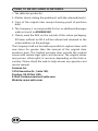
REQUIREMENTS FOR WARRANTY SERVICING
1. Prior to shipping an item back, you must first obtain a Return
Authorization Number (s) (RA#). Each item being returned must
have an individual RA#.
2. To obtain an RA #, you must either contact the retailer where
the product was originally purchased from, or contact VETTA
directly at [email protected].
3. For trouble shooting purposes, we request that the complete
unit with packaging be returned to ACUMEN INC. unless
otherwise stated by VETTA representative.
I TEMS TO BE INCLUDED IN RETURNS
1. The defective product(s)
2. A letter clearly stating the problem(s) with the returned item(s).
3. Copy of the original sales receipt showing proof of purchase
date.
4. The Company is not responsible for loss or additional damages
while in transit to ACUMEN INC.
5. Clearly mark the RA# on the outside of the return packaging.
All items without an RA # will be refused and returned to the
return address on the package.
The Company shall not be held responsible to replace items with
new items for greater than the amount of the original item
purchase price. This limited warranty does provide the original
owner with certain legal rights and recourse. The original owner
may possess other rights or recourse, depending on the state or
country. Please check the web to help answer any question and
service manual.
Acumen Inc.
101A Executive Dr., Suite 100,
Sterling, VA 20166, USA.
E-Mail: [email protected]
Website: www.vetta.com