1
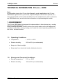
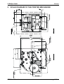
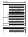
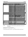
CLEARjet OEM Module
OEM Manual
Supplement to CX-one User Manual
Technical Data
V1.1
© CLEARjet GmbH
CLEARjet GmbH
CX-one
CX-one OEM-User Manual
First Edition:
Editor:
December 2004
Henriette Zirl
Copyright CLEARjet GmbH 2004
All rights reserved. No part of this publication may be reproduced, stored in a retrieval system, or transmitted, in any form
or by any means, electronic, mechanical, photocopying, recording, translation or otherwise, without prior permission in
writing.
Liability Statement
This CLEARjet product has been built in accordance with the ISO 9001standard. CLEARjet GmbH makes no claims
regarding this product, its commercial quality or its suitability for any particular task.
Please note and heed the WARNING and CAUTION labels that have been placed on the equipment for your safety.
Please do not attempt to operate or repair this equipment without adequate training. Any use, operation or repair in
contravention of this document is at your own risk. By acceptance of this system you hereby assume all liability
consequent to your use or misuse of this equipment. CLEARjet GmbH assumes no liability for incidental, special or
consequential damage of any kind. Equipment specifications, applications and options are subject to change at the sole
discretion of CLEARjet GmbH without notice.
Safety
All CLEARjet products are built in accordance with strict safety and reliability specifications. The following basic safety
tips are given to ensure safe installation, operation and maintenance of CLEARjet equipment and are not to be
considered as comprehensive on all matters of safety.
•
•
•
•
•
•
•
•
•
•
Connect equipment to a grounded facility power source. Do not defeat or bypass the ground lead.
Place the equipment on a stable surface (table) and ensure floors in the work area are dry and non-slip. Insulated
rubber floor mats are preferred.
Know the location of equipment branch circuit interrupters or circuit breakers and how to turn them on and off in
case of emergency.
Know the location of fire extinguishers and how to use them. ABC type extinguishers may be used on electrical fires.
Know local procedures for first aid and emergency assistance at the customer facility.
Use adequate lighting at the equipment location.
Maintain the recommended temperature and humidity ranges at the equipment location.
Use proper lifting techniques when moving or installing the equipment.
Use standard electrostatic discharge (ESD) precautions when working on or near electrical circuits.
Do not defeat or disconnect safety interlocks on covers. Operate the printer with the cover closed.
Conformity Regulations
This equipment generates, uses, and can radiate radio frequency energy. If it is not installed and used in accordance
with this instruction manual, it may interfere with radio communications. We confirm that the CX-one complies with the
requirements of the EM Directive 89/336/EEC. This equipment has been tested and found to be within the limits for Class
A, pursuant to norm EN55022. This product is equipped with reasonable protection against radio interference. Operation
of this equipment may possibly cause interference. In the event of interference, the user, at their own expense, will be
required to take whatever measures are necessary to correct the problem.
Notice to Users of Printers Equipped with a Contactless Smart Card Coupler
The contactless smart card coupler emits radio-frequency waves and must be used as installed and recommended by
CLEARjet. You may not modify the coupler or how it is used without the written permission of CLEARjet. You may not
operate the printer after modifying the coupler or its method of operation.
Trademarks
•
Microsoft, Windows, Windows NT are trademarks or registered trademarks of Microsoft Corporation.
•
CLEARjet is a trademark or registered trademark of CLEARjet GmbH, Grambach, Austria.
•
All other trademarks are the property of their respective owners.
CLEARjet GmbH
Schloss Spielerhof
Hauptstrasse 12
A-8071 Grambach / AUSTRIA
OEM-User Manual
http://www.clearjet.com
[email protected]
page 2 /19
CLEARjet GmbH
CX-one
CONTENTS
1.
Environment ..............................................................................................................................................4
1.1. Operating Conditions................................................................................................................................4
1.2. Storage and Transport Conditions ...........................................................................................................4
2.
Scale Diagram of the Printer Mechanism...............................................................................................5
3.
Power Supply ............................................................................................................................................6
4.
Tips on Installation and Safety................................................................................................................7
5.
Connecting additional Devices ...............................................................................................................9
6.
Integration of Chipreaders.......................................................................................................................9
6.1. Preface .....................................................................................................................................................9
6.2. Integration to standard - printer..............................................................................................................10
6.3. Integration to printer with hopper option ................................................................................................11
6.4. Function specification.............................................................................................................................12
6.5. General hints ..........................................................................................................................................16
7.
Tips on Conformity.................................................................................................................................16
8.
Connection Diagram...............................................................................................................................17
9.
Pin Assignment.......................................................................................................................................18
OEM-User Manual
page 3 /19
CLEARjet GmbH
CX-one
TECHNICAL INFORMATION CX-one – OEM
Note:
All information given in the CX-one User Manual is equally applicable to the CX-one OEM Module (performance, print areas, expected lifespan, maintenance periods, etc.).
This manual details technical data that differs from the standard device and is relevant to
the OEM Module only, as well as further information on implementing the module.
1. ENVIRONMENT
The CX-one OEM Module is designed for implementation in other devices (e.g. vending
machines, ticket dispensers).
When installing the Module in other devices you should make sure that the appropriate
conditions (e.g. airflow, cooling, heating, etc.) create the correct operating conditions for
the device, as detailed below.
1.1. Operating Conditions
•
Temperature:
+ 10°C to + 50°C
•
Relative humidity:
20% to 80% (no condensation)
•
Keep out of direct sunlight
•
Keep away from chemicals, liquids, lubricants, dust etc.
1.2. Storage and Transport Conditions
•
Storage temperature :
0°C to + 50°C
•
Relative humidity :
10% to 90% (no condensation)
OEM-User Manual
page 4 /19
CLEARjet GmbH
CX-one
74
2. SCALE DIAGRAM OF THE PRINTER MECHANISM
OEM-User Manual
page 5 /19
CLEARjet GmbH
CX-one
3. POWER SUPPLY
CX-one: Power supply requirements:
Voltage:
24V DC
+/- 1.2 V
Max. ripple:
max. 100 mV p-p
Noise (HF-ripple 20MHz) max. 300 mV p-p
current consumption:
c. 5.5A printing
c. 3A
card transport
c. 1.5A standby (heating active)
The following diagram shows the power profile of a typical card cycle. The level of power
consumption during printing depends primarily on the print image (i.e. the number of dots
being printed). As a result, practical power profiles may differ from the diagram. When
choosing your power supply you should ensure sufficient power reserves at your power
supply unit.
The connection of optional devices such as magnetic card or chipcard readers, card
feeders, etc., is not taken into account in the diagram.
Time: 1sec / Div.
Current : 1A / Div.
Printing c. 5.5A
Transport c. 3 A
Standby c. 1.5A
CX-one: current consumption [24V supply]
Printermode: standby, transport , printing
Electrical Safety:
Use power supply units which satisfy at least the standards of Norm EN-60950 (SELV
circuit). Please note that you may need to adhere to other safety standards, depending on
the function of the entire device in which the Module operates.
WARNING: The OEM Module has no excess-current-cut-out.
OEM-User Manual
page 6 /19
CLEARjet GmbH
CX-one
4. TIPS ON INSTALLATION AND SAFETY
The CX-one OEM Module is designed for installation in a variety of other devices (e.g.
vending machines, ticket dispensers). To ensure trouble-free implementation, we
recommend the following practices.
Adhering to safety standards, acquiring certification, and upholding industry
standards are entirely the responsibility of the product integrator. They are not the
responsibility of Clearjet GmbH.
•
Fire Protection:
The various components of the CX-one printer mechanism are high-quality
components and materials with flammability class V0.
However, as the device contains numerous electronic components, as well as a
heating element with a high operating temperature, the Module should be installed
in a fire-resistant casing.
Consult the relevant standards and regulations for the environment in which the
finished device/machine will be implemented (e.g. EN-60950 for data processing
devices in the office environment).
•
Mounting:
The Module is mounted using four screws (M4) at the base of the device (for
mounting position, see Section 2 – Scale Diagram of the Printer Mechanism).
If you are installing the Module without vibration dampers, ensure that you leave
sufficient space below the motor (c. 2 mm). The motor has an elastic mounting and
may vibrate lower than the base of the device.
•
Operating Position:
The optimal position for the Module is horizontal. Installing the device at a steep
angle or vertically may lead to problems with functionality.
•
Buffer space:
The scale diagram (Section 2) gives various specifications for leaving buffer areas
around the device. These are absolutely essential for the smooth running of the
printer, and also ensure easy access to the device for maintenance, service and
replacement of consumables.
It is particularly important to keep sufficient distance between the conductive parts
of the printer housing and the electronic components of the mechanism.
Depending on the printer options implemented (e.g. magnetic encoding), it may also
be necessary to leave room behind the device for card movement.
• Cables:
Make sure to use cables with sufficient wire dimensions. In particular, too high
voltage drop can lead to poor print quality.
OEM-User Manual
page 7 /19
CLEARjet GmbH
CX-one
• EMC:
To satisfy electromagnetic disturbance standards (EN-55022) it may be necessary,
depending on cable length, integration situation and housing construction, to use
damping ferrites on the connection cables ore adequate shielding methods.
• External light:
For position measurement inside the device IR light sensors are used. These have
integrated protection against external light interference, which should be sufficient
for most applications in normal light conditions. However, to prevent malfunction,
particularly in the presence of direct sunlight, you should take care that there is
sufficient protection against external light.
•
Acoustic insulation:
Appropriate vibration dampers are available for noise-sensitive applications. Please
note that fitting these dampers affects the height of the printer mechanism and also
the card-movement level.
•
Excess-current cut-out:
The OEM Module has no integrated excess-current cut-out.
Use appropriate excess-current-cut-out at power supply side.
OEM-User Manual
page 8 /19
CLEARjet GmbH
CX-one
5. CONNECTING ADDITIONAL DEVICES
Warranty exclusion:
The following technical information is for qualified personell only. This should make
integration and connection of the printer mechanism more easy.
This information implies no functional guarantee from CLEARjet GmbH.
CLEARjet GmbH is not responsible for function, quality, safety, CE-conformity and so on, if
additional units are integrated to the printer, or the printer is connected to other units.
All integration steps and modifications, which are not made from CLEARjet GmbH are in
the responsibility of the system integrator.
For connection of additional devices several connectors with controlling signals and power
supply lines are available.
Specifically, this are control lines for chipcard and magnetic card interfaces, serial
interfaces and for automatic card feeders, etc.
The functionality of these modules is varying and therefore the printer firmware must be
adapted to the particular application. As a result controlling signals can be used only with
suitably adapted firmware. For more information, contact your CLEARjet Partner.
6. INTEGRATION OF CHIPREADERS
6.1. Preface
It is frequently necessary to integrate Smart card interfaces to the printer. Therefore we
collected some general information to this subject.
Chip readers with serial (TTL-level) interface and power supply connector can be
connected to the printer. In this case the full functionality of the Chip interface inside the
printer is obtained.
OEM-User Manual
page 9 /19
CLEARjet GmbH
CX-one
OEM-User Manual
all Dimensions in mm
mounting positions
Card Position
6.2. Integration to standard - printer
page 10 /19
CLEARjet GmbH
CX-one
6.3. Integration to printer with hopper option
Possible volume for
interface integration
Card Position
all Dimensions in mm
Interface
Mounting Positions 4x M2.5
OEM-User Manual
page 11 /19
CLEARjet GmbH
CX-one
6.4. Function specification
6.4.1 Function mode - positioncontrolling
Card feeding from the front:
Enable Printer <ESC>1
Insert card from front
Card is automatically moved to
‚Printposition’
( =Chip-Readposition)
Eject the card:
without printing
Command <ESC>3
Encode CHIP-Data
Erase and reprint the card
Eject the card:
automatically after printing
Card feeding from the back:
Feed card from the Hopper
<ESC>c
Insert card from front
Card is automatically moved to
‚Printposition’
( =Chip-Readposition)
Eject the card:
without printing
Command <ESC>3
Encode CHIP-Data
Erase and reprint the card
Eject the card:
automatically after printing
OEM-User Manual
page 12 /19
CLEARjet GmbH
CX-one
6.4.2 Connecting schematic – overview:
ST 8
OPTION 2
Interface -switch
CPU,
Printercontroller
<ESC> 6
CPU-Board CJ-7007B
<ESC> 7PRINTER
CX-one
TxD (TTL)
RxD (TTL)
CHIP- Interface
Power supply
RS 232 Driver
RS-232
HOST
RS-232
CHIP
RS-232 Interface - switch
The CX-one Printer contains two separate RS-232 interfaces, one for controlling the
printer mechanism and the other for controlling the chip-reader.
To control both units (printer and chipreader) with one interface we integrated a special
‚interface – switch’ to the CX-one. With the command <ESC>6 (transparent-mode) the
RS232-HOST interface can be switched from the printer to the chip-reader unit.
OEM-User Manual
page 13 /19
CLEARjet GmbH
CX-one
Function of interface - switch:
RS-232
HOST
•
•
•
<ESC> 6
<ESC> 7PRINTER
CX-one
Printercontroller
CHIP - Interface
RS-232
CHIP
In normal operating mode the printer-unit is controlled via the interface RS232
HOST, and the chipreader via RS232 CHIP
With the command <ESC>6 the ‚transparent mode’ is activated.
The HOST interface path is switched from the printer to the chip-reader
To switch back the interface path to the normal operating mode, use the
command <ESC>7PRINTER
6.4.3 Electrical connections
The connector ST8 on the CPU-Board is reserved for connecting chipinterfaces.
To connect this interfaces several power-supply pins and the datalines #TXD1 und #RXD1
(see pin assignment ST8) are available.
Please pay attention to connect TTL-level signals only at the datalines. Connecting of
RS-232 level signals (+/-12V) is not possible and will destroy the printer-electronic.
Interface parameters:
Baudrate:
Dataformat:
Signal level:
9600 Bd
8/N/1
TTL
Note:
If the ‚transparent mode’ is not used, all interface parameters can be configured freely
(max. Baudrate 57600 Bd)
Baudrate – conversion:
The Baudrate of the ‚HOST’ interface can be selected up to 57600 Bd (see DIP-switch
settings). Since the Baudrate of the ‚CHIP’ interface (transparent mode) is fixed to 9600 Bd
the printer converts baudrates automatically.
Please note, that small delays may arise due to different transmission speed.
OEM-User Manual
page 14 /19
CLEARjet GmbH
CX-one
Power supply for CHIP-interfaces
To supply the chip-interfaces several outputs on connector ST8 are available (see pin
assignment). As an option it is possible to install an additional DC/DC-Converter to the
CX-one CPU-Board. This converters are available with different power and voltage levels.
VCC, GND :
internal power supply of printer electronics
for external Modules: 5V +/-5%, max. 50mA
+24V, GND :
24V output (directly connected to the supply of the printer
mechanism)
for external Modules: max. 0.5A
Vout, 0V :
Output from optional DC/DC converter
dependant on used converter: 3.3V, 5V, 12V or 15V
galvanic separation is possible
output power: 2 – 6 W, depending on converter type
Please note that you should take these additional output currents into account when
selecting your power supply unit.
6.4.4 Connecting the CHIP-contact unit :
To integrate commercial Chipreaders, special printer version with integrated contact-units
are available.
The printer moves the chipcard automatically to the reading position and contacts the
chipcard. The chipcontact-lines can be used freely (cable with open end).
Position of the contact unit complies to ISO 7810.
Kontakt unit – pin assignment:
Pin No.:
1
2
3
4
5
6
7
8
9
10
Signal
Switch1
Switch2
C8
C4
C7
C3
C6
C2
C5
C1
Description
Cardsensor
Cardsensor
N.U.
N.U.
I/O
CLK
VPP
RST
GND
CHIP-VCC
Note:
The cardsensor (signal SWITCH1 und SWITCH2) is a potential free switching contact. The
switch is closed, when the smartcard is contacted. (capacity: max. 12V / 100mA DC )
OEM-User Manual
page 15 /19
CLEARjet GmbH
CX-one
6.5. General hints
Temperature:
Please note, that there can be higher temperature levels inside the device (depending on
operating situations). Make shure, that the function of the integrated unit is compatible to
this conditions.
Disturbances:
The printer produces, dependent on operating situations, electrical and magnetic fields.
Specially in the near of the motors, this may cause function-problems of integrated units
( e.g.: RF-Chipreaders).
7. TIPS ON CONFORMITY
Please note that our conformity declaration (CE-certification) only applies to our fully
assembled devices.
The OEM printer mechanism is a component designed for integration into other devices
(e.g. vending machines, ticket dispensers, etc.). Therefore it is distributed without housing,
power supply units and cables.
As housing, power supply units and cables are important for certification, we are unable to
supply conformity declarations for OEM Modules.
Independently we confirm that the modules are designed to fulfill all relevant standards for
certification if correctly installed and if adequate EMC techniques for integration are used.
OEM-User Manual
page 16 /19
CLEARjet GmbH
CX-one
8. CONNECTION DIAGRAM
OEM-User Manual
page 17 /19
CLEARjet GmbH
CX-one
9. PIN ASSIGNMENT
ST7 CPU-Board
Option 1
OEM-User Manual
Power Supply
Deactivate Handshake from PC
Signal Ground
Data Carrier Detect Input
Data Set Ready Input
Receive Data Input
Request To Send Output
Transmit Data Output
Clear To Send Input
Data Terminal Ready Output
Ring Indicator Input
Signal Ground
Data Line
Data Line
Power Supply from Bus
Signal Ground
HOST
FEED1
FEED2
IN1
IN2
VCC
+24V
GND
GND
Deactivate Handshake from PC
Receive Data Input
Request To Send Output
Transmit Data Output
RS-232
1
2
3
4
5
6
7
8
24V Power Supply
24V Power Supply
24V Power Supply
24V Power Supply
24V Power Supply
24V Power Supply
Power Supply GND
Power Supply GND
Power Supply GND
Power Supply GND
Power Supply GND
Power Supply GND
RS-232 CHIP
+24V
+24V
+24V
+24V
+24V
+24V
GND
GND
GND
GND
GND
GND
n.c.
loop to Pin 19
RXD0
RTS0
TXD0
n.c.
loop to Pin 14
n.c.
GND
DCD1
DSR1
RXD1
RTS1
TXD1
CTS1
DTR1
RI1
GND
D+
DVBUS
GND
USB
DB9 male - PIN1
PIN6
PIN2
PIN7
PIN3
PIN8
PIN4
PIN9
PIN5
DB9 male - PIN1
PIN6
PIN2
PIN7
PIN3
PIN8
PIN4
PIN9
PIN5
1
2
3
4
5
6
7
8
9
10
11
12
13
14
15
16
17
18
19
20
21
22
23
24
25
26
27
28
29
30
31
32
33
34
Open Drain Output max. 200mA
Open Drain Output max. 200mA
Input / TTL Level
Input / TTL Level
5V Power Supply Out
24V Power Supply Out
Signal and VCC Ground
Signal and VCC Ground
HOPPER
ST3 CPU-Board
page 18 /19
1
2
3
4
5
6
7
8
9
10
11
12
13
14
VCC
VCC
#TXD1
I/O1
#RXD1
#RTS1
GND
GND
I/O2
I/O3
I/O4
0V
VOUT+
+24V
5V Power Supply Out
5V Power Supply Out
Transmit Data Output / TTL Level
I/O Signal for Options / TTL Level
Receive Data Input / TTL Level
Request To Send Output / TTL Level
Signal and VCC Ground
Signal and VCC Ground
I/O Signal for Options / TTL Level
I/O Signal for Options / TTL Level
I/O Signal for Options / TTL Level
GND from DC/DC Converter
Power Supply from DC/DC Converter
24V Power Supply Out
ST9 CPU-Board
Option 3 ( RS232-1)
1
2
3
4
5
6
7
8
9
10
11
12
DCD1
DSR1
RXD1
RTS1
TXD1
CTS1
DTR1
RI1
GND
VCC
VOUT+
0V
Data Carrier Detect Input
Data Set Ready Input
Receive Data Input
Request To Send Output
Transmit Data Output
Clear To Send Input
Data Terminal Ready Output
Ring Indicator Input
Signal Ground
5V Power Supply for Options Out
Power Supply from DC/DC Converter
GND from DC/DC Converter
NOTE:
1
2
3
4
LED 1 red
LED 2 yellow
LED 3 green
VCC
Cathode
Cathode
Cathode
Common Anode
LED
ST3 PH-Controller
Board
external LED
Modem Connection
ST8 CPU-Board
Option 2
Various options
CX-one
Parallel to CPU Board ST3 Pin22 - 30
CLEARjet GmbH
This connector is located on the PH-controller board (on the left / rear
board edge)
Standard LEDs may be directly connected.
Diode current: IF = c. 8 mA (at VF = 1.2 – 1.4V)
Current limiting resistors (470 Ohm – 5 V) are located on the PH-controller board.
OEM-User Manual
page 19 /19