1
1. OVEN INSTALLATION
Carry the oven, complete with its support,
if any, to the place of installation. Make
sure there is enough clearance around the
appliance for proper ventilation and
cleaning. The oven base and frame legs
must rest on a firm, uniform and flat
surface. No anchoring of the frame into
the ground is required. After installing the
appliance, adjust its horizontality, if
necessary, by turning the M12 screws:
first, place the air level longitudinally and
then crosswise. The oven being level, lock
the adjusting screws.
close to the appliance as possible, so that
the fitted cord can be plugged into an
outlet. To this end, do not use extension
cables.
Depending on its configuration, this
appliance may be supplied with either a
three-pole or a four-pole power cord of
appropriate length and with a yellowgreen earthing line. The free end of this
cord must be connected to a EEC-unified
plug, consistent with the IEC 309-2 'Plugs
and Sockets for Industrial Use' standard
and properly sized for the supply voltage
and rated input power of the appliance as
shown on the wiring diagram and in the
section 'Technical Data'.
2. ELECTRIC EQUIPMENT DATA
The oven electrics comprises the following
devices:
- One ON/OFF lever switch protected
against unintentional use on the oven
front.
- Power relays in order to integrate the
heating resistors into the circuit.
- A safety transformer for supplying the
auxiliary circuit with low voltage power.
- RC cells fitted on the feeder of the
contactor / relay and thermostat trigger
circuit in order to limit surges caused by
the breaking of induction and/or
resistance circuits, in conformity with the
Electromagnetic Compatibility (EMC)
regulations for the suppression of EMI
effects.
- One thermostat for controlling and
regulating the temperature in the
cooking chamber.
- One safety thermostat intended to
disconnect the main power supply
circuit, if necessary.
- Enclosed-type heating resistors, featuring
AISI 321 stainless steel external tube and
a 100-mm neutral area, to reduce heat
transfer to the supports. Heating resistor
element made of 80-20 nichrome, with
MgO ceramic insulation.
- Branch and connecting terminals located
inside the controls housing.
- Control thermostat pilot lamps.
- Wiring of the different electric devices of
the appliance, with cables suitable for its
intended duty and line surge limits.
3. MAINS CONNECTION
Connecting the appliance to the mains
and its initial start-up shall be done by an
expert and qualified installer according to
the technical and legal regulations in force
in the user's country. Lay on a line as
The specialist installer shall install the
following components as may be required
to comply with the applicable norms in
the user's country:
- One appropriate pin plug
- One line breaker
- One hot-wire in addition to a differential
switch of adequate sensitivity for the
leakage current of the resistors.
The appliance must be earthed.
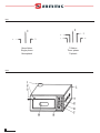
Make the connection, as technically
prescribed, bearing in mind both the
cyclical phase connecting sequence and
the colour code of the leads (Fig. 1):
- L1 = phase - L2 = phase - L3 = phase
- N/MP = Neutral - blue-coloured
- PE/Earth = GREEN/YELLOW stripe
sheathed wire
After connecting the oven power supply
protection systems, test for the
differential switch efficiency with the
instrument intended for this purpose.
Verify that there are no combustible or
other objects whatsoever inside the oven
and that the oven is ready for testing.
Check that the ON/OFF switch of the
appliance is in the 0/OFF position.
Turn the knob of the thermostat to set the
temperature at an average value of about
150ºC.
Put the ON/OFF switch lever in the I/ON
position.
Check for current consumption and
correct operation of all the lamps
installed.
Wait for the rupture of the thermostat
circuit and turn the ON/OFF switch to
0/OFF.
The oven is now ready to work normally.
Figura 1.
4. DESCRIPTION OF THE APPLIANCE
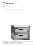
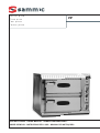
The oven's external structure is of
STAINLESS material.
The front of the oven is wholly made of
stainless steel.
- Cooking chamber of stainless steel plate.
- Oven's cooking sole made of movable
and repairable refractory tiles allowing
thorough cleaning of the cooking
chamber.
- 80-mm diameter round smoke and
steam exhaust spout to be connected by
means of an adequate pipe (not
supplied) to the room's fume exhaust
duct. This spout is special for the
exhaust of hot smoke and steam
developing during the cooking process.
- Complete insulation of the cooking
chamber by means of long-fibred rock
wool quilted mat, a non-toxic and nonpolluting material.
- Enclosed-type heating resistors,
manufactured according to the IEC
technical standards, from fine and longlasting materials.
- ON/OFF switch on the front of the oven.
- Thermostat for inside temperature
control and regulation in a range up to
500ºC programmable with the graduated
knob on the front of the oven.
- One special safety thermostat protects
the appliance against overheating for any
reason whatsoever during its operation.
- Internal lighting ON/OFF switch.
- Depending on the power demand and
size of the oven, the same will be
prepared for either single-phase 230V or
three-phase 400V, alternating current,
50 or 60Hz supply, with tolerances as
per IEC 8-6 of 3/1990.
- The front door includes an optimally
efficient, heat-insulator Pyrex pane,
except on the MINI model.
- Internal lighting permits the cooking
process to be supervised.
- The oven door swings on hard-wearing
hinges with gravity closing for easier
operation.
The handle of the oven door is made of
heatproof material. Control of the heating
resistors is by means of an integrated-type
electromechanical system that includes
the complete and reliable circuitry of the
heating resistors with power relays as well
as the auxiliary circuit controlling the
thermostats, relays and lamps.
Electric safeties consist in the following
circuit elements, built according to the
referenced standards:
- Mains galvanic isolation by means of the
ON/OFF switch on the front control
ENGLISH 5