1
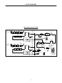
REAR PANEL FEATURES
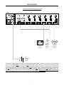
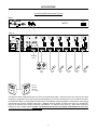
CMA30, CMA60, & CMA120 Rear Panels
pre
out
channel 2
channel 1
phantom pwr
auto mute
manual mute
mute -40
level -20
phantom pwr
auto mute
manual mute
mute -40
level -20
trim
ina
priority
25V
compressor
6.3A - 115V
out
50V
min
70V
3.15A -230V
remote
level
+10V c
auto mute
on
off
priority
ina
max
trim
min
on
off
priority
line
mic
ina
max
trim
min
on
off
max
trim
min
on
off
priority
line
mic
ina
priority
line
mic
ina
max
trim
min
on
off
ina
max
min
on
off
priority
line
mic
line
mic
min
mute/
chime stacking in
tel
+
USE ONLY WITH
250V FUSE
trim
line
mic
max
threshold adjust
max
min
8
R
C
~ 115/230V
channel 3
phantom pwr
auto mute
manual mute
mute -40
level -20
nom
amp
in
channel 4
phantom pwr
auto mute
manual mute
mute -40
level -20
nom
min
rec
out
channel 5
phantom pwr
auto mute
manual mute
mute -40
level -20
nom
line
out
channel 6
phantom pwr
auto mute
manual mute
mute -40
level -20
nom
com
max
nom
chime
level
4
E158021
LISTED 2 Z 91
COMMERCIAL
AUDIO EQUIP
R
send/return
an affiliate of
Rauland-Borg Corp
direct
nom
BIAMP SYSTEMS
120watt
output
xfmr
+
+
+
+
+
+
AC 50/60 Hz 375 VA
CMA350 Rear Panel
send/return
115
R
pre
out
amp
in
inal
max
min
priority
R
WARNING:
compressor
do not change
AC voltage switch
when power is on.
out
350 watt
output
min
inal
max
min
trim
inal
on
off
on
off
line
mic
line
mic
channel 3
phantom pwr
auto mute
manual mute
mute -40
level -20
max
min
priority
priority
on
off
C
trim
channel 4
phantom pwr
auto mute
manual mute
mute -40
level -20
trim
inal
channel 2
max
min
priority
trim
inal
max
min
trim
inal
max
min
priority
priority
on
off
channel 1
phantom pwr
auto mute
manual mute
mute -40
level -20
phantom pwr
auto mute
manual mute
mute -40
level -20
nom
rec
out
trim
LISTED 2 Z 91
COMMERCIAL
AUDIO EQUIP
channel 5
phantom pwr
auto mute
manual mute
mute -40
level -20
nom
line
out
E158021
phantom pwr
auto mute
manual mute
mute -40
level -20
nom
an affiliate of Rauland-Borg Corp.
min
nom
Portland, Oregon
max
nom
channel 6
chime
level
nom
CMA350
BIAMP SYSTEMS
on
off
on
off
auto mute
threshold adjust
max
min
line
mic
line
mic
line
mic
line
mic
tel
xfmr
direct
stacking in
70V 50V 25V 8
~ 115/230V
channel 5
channel 4
channel 3
channel 2
channel 1
mute/
chime
6.3A - 115V
com 4
remote
level c
+
+
+
+
+
+10V
+
3.15A -230V
+
USE ONLY WITH
250V FUSE
channel 6
AC 50/60 Hz 700 VA
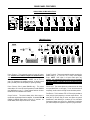
Power Entrance: This receptacle accepts a 3-prong AC power
cord. WARNING: DO NOT REMOVE OR DEFEAT THE GROUND PRONG, AS
THIS CONSTITUTES A SHOCK HAZARD. The removable lower portion
of the receptacle holds the AC fuse. NOTE: See AC Fuse on
page 7 for replacement by qualified personnel. A chassis ground
post is provided (next to the receptacle) for system grounding.
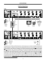
Output Terminals: These screw terminals provide connection for
speaker loads (4Ω, 8Ω, 25V, 50V, 70V, or 100V) at the amplifier
output. NOTE: 100V output is an export model option only.
Power Selector Switch (model CMA350 only): This switch
selects either 115 Volt or 230 Volt AC operation for model CMA350
(see Modifications on pg. 7). Power Selector Switches for other
models are on the underside of the chassis.
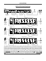
Chime Level: This control adjusts the volume level of the chime
tone (see Mute/Chime on next page). To turn the chime tone off
completely, set this control to the fully counter-clockwise position.
Output Selector: This switch selects either direct output or
transformer coupled output from the amplifier. On models CMA60,
CMA120, & CMA350 direct output is from the 4Ω terminal. On
model CMA30, direct output is from the 8Ω terminal.
Send/Return: This 3-conductor TRS 1/4" Phone jack provides an
insert point for signal processing or remote control devices. It is
wired with Tip as send, Ring as return, and Sleeve as ground.
Send/Return is after Stacking In, Loudness, & Tone, but before
Compressor, Master Level, & Low Cut. Send/Return is a switching
jack, which interrupts the signal flow only when a plug is inserted.
WARNING: THE LOUDSPEAKER OUTPUTS POSE A RISK OF HAZARDOUS
ENERGY. LOUDSPEAKER CONNECTIONS MUST BE MADE PROPERLY.
THE OUTPUT TERMINAL COVER MUST BE INSTALLED WHEN THE DEVICE
IS ENERGIZED.
4