1
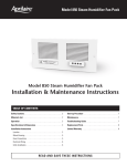
Model 76 Dehumidifier Control
Installation Instructions
READ AND SAVE THESE INSTRUCTIONS
The Model 76 is for use with any dehumidifier as an EXTERNAL CONTROL,
including Aprilaire Models 1710A, 1730A, 1750A, 1770A.
The Model 76 can also be used as a communicating REMOTE CONTROL
with Aprilaire Models 1710A, 1750A, 1770A.
(See OVERVIEW on page 3 for details.)
Safety Instructions
WARNING
1. Improper installation may cause property damage or injury. Installation, service,
and maintenance must be performed by a qualified service technician.
2. 120 Volts may cause serious injury from electric shock. Disconnect electrical
power before starting installation or servicing. Leave power disconnected until
installation/service is completed. This control is not a 120 Volt (line voltage)
device.
CAUTION
1. Read all instructions before beginning installation.
2. Do not use in pool applications. Pool chemicals can damage the control.
3. Do not use solvents or cleaners on or near the display and circuit board.
Chemicals can damage components.
1
Table of Contents
Safety Instructions . . . . . . . . . . . . . . . . . . 1
Overview . . . . . . . . . . . . . . . . . . . . . . . . . . . 3
Specifications . . . . . . . . . . . . . . . . . . . . . . 3
Location Recommendations . . . . . . . . . . 4
Installation
Mount Control . . . . . . . . . . . . . . . . . . . . . 5
Replacing a 1730A
Manual Dehumidistat . . . . . . . . . . . . . . 6
Wiring to 1730A . . . . . . . . . . . . . . . . . . . . 8
Wiring to 1710A/1750A/1770A
External Control . . . . . . . . . . . . . . . . . . . 9
Remote Control . . . . . . . . . . . . . . . . . . 10
OVERVIEW
System Checkout
Power Up . . . . . . . . . . . . . . . . . . . . . . . .
Test Mode . . . . . . . . . . . . . . . . . . . . . . . .
Humidity/Dryness Level Setting . . . . . .
Offset . . . . . . . . . . . . . . . . . . . . . . . . . . .
Turning On and Setting the Control . . . .
Sequence of Operation
External Control . . . . . . . . . . . . . . . . . .
Remote Control . . . . . . . . . . . . . . . . . .
11
13
13
13
14
15
15
Troubleshooting
Error Codes
External Control . . . . . . . . . . . . . . . . . . 16
Remote Control . . . . . . . . . . . . . . . . . . 16
Troubleshooting Guide . . . . . . . . . . . . . . 18
The Aprilaire® Model 76 Dehumidifier Control provides control of the dehumidifier from the
living space.
The control can be installed as an EXTERNAL CONTROL, allowing the homeowner to set and
adjust the humidity setting and turn dehumidification on or off from a convenient location. In
this application, the Model 76 uses an onboard sensor to monitor the relative humidity (%RH)
in the space in which it is located and displays the measured relative humidity on the digital
display.
The control can also be installed to function as a REMOTE CONTROL if the dehumidifier
is located where it is not easy or convenient to access. The control can be installed in any
location within the living space, with the dehumidifier installed in the area to be dehumidified,
such as a crawl space, attic, or basement. The dryness level is set on the control and
communicated to the dehumidifier. The dehumidifier communicates the measured relative
humidity in the space being dehumidified back to the Model 76 Control where it is displayed
on the digital display.
SPECIFICATIONS
2
ELECTRICAL
External
Remote
Input Voltage and Current
Voltage: 24VAC +/-20%
Current: 25mA (nominal),
50mA (max.) at 24VAC
Voltage: 9VDC (supplied by
dehumidifier control board)
Output
Dry Contact, Normally Open
Communication (RS485)
CONTROL
External
Remote
Control Range
40% – 80% RH
1 (less dry) – 7 (more dry)
65°F – 40°F Dew Point
Accuracy
+/-5% RH
Differential
3%
Low Limit
40°F Dew Point
50°F Dry Bulb
High Limit
99°F Dry Bulb
105°F Dry Bulb
See Dehumidifier Specifications
3
LOCATION RECOMMENDATIONS
INSTALLATION
As a REMOTE CONTROL, the Model 76 can be mounted wherever is convenient for the
homeowner.
MOUNT CONTROL
Follow the recommendations below when installing the Model 76 as an EXTERNAL CONTROL.
MOUNT CONTROL
•In an area the homeowner wants to
monitor and control moisture levels.
•On an interior wall.
If replacing a control mounted in the living space, see Control Mounted in Living Space on
page 6.
DO NOT MOUNT CONTROL
Figure 2 – Disassemble Control
• In the flow of a supply register.
•Behind doors, in corners or other dead air spaces.
•Approximately 5’ off the floor.
•In direct sunlight, near lighting fixtures, or other
appliances that give off heat.
•At least 18” from an outside wall.
•On an outside or unconditioned area wall.
T
AR
AP
LL
PU
A
B
C/R/+
DH
DH
•In stairwells or near outside doors.
•On a wall with concealed pipes or ductwork.
BACKING
PLATE
Figure 1 – Mounting Control
FRONT COVER
90-1631
Figure 3 – Mount Backing Plate
ANCHOR
90-1640
A
B
C/R/+
DH
DH
BACKING PLATE
SCREW
90-1632
4
5
Required Components
If the control is mounted on A 1730A dehumidifier:
18 – 24 gauge wire (field supplied) – 4 wires required, run new cable as needed.
(2) #8 x 1-1/2” mounting screws (supplied)
(2) Anchors (supplied)
NOTE: The Model 76 is installed in the living space and not on the dehumidifier.
See LOCATION RECOMMENDATIONS on page 4.
1.Level the backing plate on the wall and mark the mounting holes and wire access location
on the wall.
2.Pull knob from the dehumidistat cover and remove cover from the control base.
1. Disconnect power to the dehumidifier and HVAC system.
2.Drill two 3/16” mounting holes and a 3/4” wire access hole. See Figure 3.
3.Remove the four screws from the base plate and pull the dehumidistat off the unit until
4”– 6” of wire is outside of the unit.
3.Install the drywall anchors flush with the wall surface. Note: Mounting holes on the backing
plate are designed to fit on a horizontal J-box.
4.Cut the wires and use metal tape to secure the leads to the inside of the unit, preventing
contact with the blower.
4.Run a 4-wire cable from the dehumidifier to the wall mount location and through the square
hole in the backing plate.
5.Remove the gasket from the base plate.
5.Secure the backing plate to the wall using the two #8 x 1-1/2” screws.
REPLACING A 1730A MANUAL DEHUMIDISTAT
6.Install the insulated cover plate (Service Part 4927) and gasket over the opening, using the
screws removed in step 3. See Figure 5.
7.Remove the wiring access panel on the outlet panel. See Figure 6.
8.Unplug the REMOTE terminals from the circuit board, remove the two wires and cut off the
bare leads. Once cut, the wires may remain in the unit.
STEP 1 – Remove the Current Manual Control
9.Replace REMOTE terminals on circuit board and leave wiring access panel off for Model 76
wiring.
If the control is mounted in the
living space:
10.Proceed to WIRING section on page 8.
Figure 4 – Manual Dehumidistat
1. D
isconnect power to the dehumidifier
and HVAC system.
2.Pull knob from the dehumidistat cover and
remove cover from the control base.
Figure 5 – Inlet with Cover Plate
COVER PLATE
SERVICE PART 4927
Figure 6 – Wiring Access Panel
on Outlet
WIRING ACCESS PANEL
3.Remove the four screws from the base
plate.
4.Pull the dehumidistat off the wall until wire
nuts are exposed.
5.Remove dehumidistat leads.
6.The existing 2-wire cable can remain. The Model 76 wiring requires 4 wires. Install more
wires as needed.
7.Mount the Model 76 control following steps 1-5 in the MOUNT CONTROL section above.
Reuse the existing wire access hole and wiring as needed.
8.Connect the existing wires (from 1730A REMOTE terminals) to the DH terminals and
connect the remaining two wires to the C/- and R/+ terminals on the Model 76 backing
plate.
9.Push excess cable into the wire access hole and fill the hole with insulation. Note: Failure
to seal the hole can cause drafts to enter the control and affect sensing accuracy.
90-1642
90-1633
10.Proceed to WIRING section on page 8.
6
7
MODEL 76 EXTERNAL CONTROL TO 1710A /1750A /1770A
WIRING
1.Disconnect power to the dehumidifier and HVAC system.
STEP 2 – Supply 24VAC To The Model 76 Control
The Model 76 control requires 24VAC when installed as an EXTERNAL CONTROL for the 1730A.
Pulling power from the HVAC system is the recommended method.
3.Connect one wire from the DH terminal on the Model 76 to the DH terminal on the control
board.
4.Connect the other wire from the DH terminal on the Model 76 to the Rf terminal on the
control board.
5.Connect the wires from the C/- and R/+ terminals on the Model 76 to the HVAC or
thermostat C and R terminals.
6.Set SYSTEM SETUP switch to EXTERNAL. See Figure 9.
7.Replace the control door on the dehumidifier.
8.Snap the Model 76 front cover on the backing plate. The 6-pin terminal aligns with the
terminal block receptacle on the backing plate.
Figure 8 – Model 76 External Control to
1710A/1750A/1770A Wiring
DEHUMIDIFIER
CONTROL BOARD
EXISTING WIRING
C
G
W
W
Y
Y
DH
Figure 7 – Model 76 to 1730A Wired to HVAC System
Wiring Note: The dehumidifier Rf
and Cf terminals must be powered
from the transformer that powers
the Model 76 Control.
EXISTING WIRING
ADDITIONAL MODEL 76 WIRING
A
B
C/R/+
DH
DH
ON
C
G
4
R
3
R/+
DH
HVAC EQUIPMENT
R
2
A
B
C/-
THERMOSTAT
SYSTEM SETUP
LOCAL
HVAC FAN OFF
PRIMARY
VENT-AUTO
EXTERNAL
HVAC FAN ON
PRIMARY/SECONDARY
VENT-TIMED
90-1538
A B + Rf Cf Gs Gh W DH FLOAT
ODT
SWITCH SENSOR REMOTE
HVAC EQUIP
MODEL
76
Figure 9 – Model 76
External Control Dip
Switch Configuration
1
ADDITIONAL MODEL 76 WIRING
VENT DEH
DAMPERS
MODEL 76 TO 1730A
1. Disconnect power to the dehumidifier and HVAC system.
2. If replacing a dehumidistat that was in the living space, follow steps 3-6. If replacing a
dehumidistat that was on the dehumidifier, follow steps 7-13.
3. Connect the wires from the C/- and R/+ terminals on the Model 76 to the HVAC or
thermostat C and R terminals.
4. Connect the existing wires connected to the REMOTE terminals to the DH terminals on
the Model 76.
5. Snap the Model 76 front cover on the back plate. The 6-pin terminal aligns with the
terminal block receptacle on the back plate.
6. Proceed to SYSTEM CHECKOUT on page 11.
7. Remove the wiring access panel (if not already removed) on the dehumidifier outlet panel.
8. Unplug the REMOTE terminals from the circuit board.
9. Connect the wires from the DH terminals on the Model 76 to the REMOTE terminals and
plug the terminals back into the unit circuit board.
10.Connect the wires from the C/- and R/+ terminals on the Model 76 to the HVAC or
thermostat C and R terminals.
11.Replace the wiring access panel on the dehumidifier.
12.Snap the Model 76 front cover on the backing plate. The 6-pin terminal aligns with the
terminal block receptacle on the backing plate.
13.Proceed to SYSTEM CHECKOUT on page 11.
2.Remove the control door on the dehumidifier inlet panel.
90-1537
THERMOSTAT
R
C
G
W
Y
HVAC
EQUIPMENT
R
C
G
W
Y
FLOAT
SWITCH
REMOTE
G-STAT
R-HVAC
G-HVAC
90-1641
8
9
MODEL 76 REMOTE CONTROL TO 1710A /1750A /1770A
SYSTEM CHECKOUT
1.Disconnect power to the dehumidifier and HVAC system.
2.Remove the control door on the dehumidifier inlet panel.
POWER UP
3.Connect one wire from the A terminal on the Model 76 to the A terminal on the control
board.
1.Check all wiring.
2.Plug in dehumidifier and restore power to the HVAC system.
4.Connect one wire from the B terminal on the Model 76 to the B terminal on the control
board.
5.Connect one wire from the R/+ terminal on the Model 76 to the + terminal on the control
board.
3.Turn on/off switch on dehumidifier ON. After a 4 second start up sequence all buttons on the
Model 76 will be functional.
• The control will be OFF.
6.Connect one wire from the C/- terminal on the Model 76 to the – terminal on the control
board.
• The humidity setting will be 60% if wired for EXTERNAL CONTROL. The dryness level will
be set to 3 if REMOTE CONTROL.
7.Set SYSTEM SETUP switches to LOCAL and PRIMARY, See Figure 11.
• The control will display the measured humidity.
– EXTERNAL CONTROL displays humidity measured by the control in it’s installed space.
– REMOTE CONTROL displays humidity measured by the dehumidifier in it’s installed space.
8.Replace the control door on the dehumidifier.
9.Snap the Model 76 front cover on the backing plate. The 6-pin terminal aligns with the
terminal block receptacle on the backing plate.
Figure 10 – Model 76 Remote Control to
1710A/1750A/1770A Wiring
DEHUMIDIFIER
CONTROL BOARD
ON
4
LOCAL
HVAC FAN OFF
PRIMARY
VENT-AUTO
3
90-1537
Humidity Setting
and Offset
Adjustment
SYSTEM SETUP
2
R/+
DH
Rf Cf Gs Gh W DH FLOAT
ODT
A B + HVAC EQUIP
SWITCH SENSOR REMOTE
A
B
C/-
Model 76 Control
Figure 11 – Model 76
Remote Control Dip
Switch Configuration
1
VENT DEH
DAMPERS
MODEL
76
Figure 12 –
External Control
EXTERNAL
HVAC FAN ON
PRIMARY/SECONDARY
VENT-TIMED
90-1538
Control must be
ON to adjust offset
and setting.
Measured
Humidity or
Setting
Control On/Off
Model 76 LCD Display
SET: Shows when
humidity setting
displayed or being
changed.
Solid ON:
Control On
Blinking ON:
Dehumidifying
DH
OFF: Control Off
*
Blinking ON + : Control Limit Exceeded.
See Control Limits, page 15.
90-1636
10
11
Figure 13 –
Remote Control
TEST MODE
Model 76 Control
1.Press and hold the ON button for 5 seconds to enter Test Mode.
a. Verify the measured humidity is displayed on the Model 76 screen.
Dryness Level
b. Verify dehumidifier turns on, and ON blinks on the Model 76 screen.
Control must be
ON to adjust.
c. Verify the
is displayed on the Model 76 screen when wired as a REMOTE CONTROL.
*
2.After 5 minutes or after pressing the OFF button, the control will enter Off mode.
a. Verify the dehumidifier turns off.
Measured Humidity
in Remote Location
or
Dryness Level Setting
Control On/Off
Model 76 LCD Display
Does not display
when setting
dryness level
Solid ON:
Control On
Blinking ON:
Dehumidifying
OFF: Control Off
90-1636
SET: Shows when
dryness level
setting displayed
or being changed.
HUMIDITY / DRYNESS LEVEL SETTING
•The control must be ON to adjust the humidity or dryness level setting.
•The
(up) and
(down) buttons are used to increase or decrease the setting.
•The first press of either button will display the current setting and SET on the LCD display.
•Each subsequent push of the up or down buttons will change the setting by 1% or 1 dryness
level.
•If a button is held down, the setting will continually change by 1% or 1 dryness level every
1/2 second for as long as the button is pressed.
•The control will return to Normal Mode, displaying the measured humidity, 5 seconds after
the last button press/release.
OFFSET
When the Model 76 is installed as an EXTERNAL
CONTROL, an offset can be applied to the humidity
reading to avoid discrepancies with other humidity
measuring devices in the home. Allow 48 hours for
the control to acclimate before applying an offset. The
control must be ON to enter the Offset screen.
Figure 14 – Offset Screen
NOTE: This feature is not available when the control
is installed as a REMOTE CONTROL.
•Press and hold the OFF button for 5 seconds to
enter the Offset screen.
90-1638
•The
buttons can be used to set an offset
value between -5% RH and +5% RH.
•The control will return to Normal Mode, displaying
the measured humidity, 5 seconds after the last
button press/release.
12
13
TURNING ON AND SETTING THE CONTROL
SEQUENCE OF OPERATION
External Control
External Control
1.Press the ON button.
Normal Mode
2.Use the
buttons to set the control at 59%.
Increasing the humidity setting will decrease dehumidifier run time, allowing for higher
humidity levels.
Decreasing
the humidity setting will increase dehumidifier run time, allowing for lower
humidity levels.
TABLE 1 – %RH (+/-5%) Based on Dryness
Remote Control
Level Setting & Indoor Temperature
1.Press the ON button.
buttons to set the
2.Use the
control to a 3 dryness level.
Increasing the dryness level will
increase dehumidifier run time,
allowing for lower humidity levels.
Decreasing the dryness level will
decrease dehumidifier run time,
allowing for higher humidity levels.
The dryness level settings can be
approximated to relative humidity (%RH)
using Table 1.
Dryness
Level
Setting
Indoor Temperature (°F)
65
1
70
75
80
84%
71%
60%
2
86%
73%
61%
52%
3
74%
63%
53%
45%
4
64%
54%
45%
39%
5
55%
46%
39%
33%
6
47%
39%
33%
28%
7
40%
34%
28%
24%
Note: This table is for reference only.
•When the measured humidity is greater than the setting, the control will activate the
dehumidifier output, the dehumidifier will begin dehumidifying and ON will blink on the
LCD display.
•When the measured humidity falls 3% below the setting, the control will deactivate the
dehumidifier output, the dehumidifier will stop dehumidifying and the LCD will display a
solid ON.
Control Limits
•If the control measures a dew point below 40°F OR a temperature above 99°F, the control
will deactivate the dehumidifier output if actively dehumidifying, the dehumidifier will stop
dehumidifying, and ON and will blink on the LCD screen.
•The control will resume normal operation when the measured dew point is greater than 45°F
or the measured temperature is below 94°F, whichever control limit was exceeded.
*
Remote Control
Normal Mode
•Once during every Cycle Period (set by the dip switches in the dehumidifier) the dehumidifier
blower and dehumidifier damper output will turn on and sample the air in the area served by
the dehumidifier. Sampling will also occur whenever the dryness level setting is increased on
the Model 76 Control.
•After three minutes, the dew point of the incoming air is measured and compared to the
dryness level set on the Model 76 Control. If the dew point of the incoming air is above the
setting, the compressor turns on and ON will flash on the Model 76 screen.
•The dew point of the incoming air is continuously monitored during compressor operation.
When the dew point of the incoming air falls below the dryness level setting, the dehumidifier
compressor and blower will turn off and ON will stop flashing on the Model 76 screen.
Control Limits
The control limits are determined by the dehumidifier.
•If the dehumidifier senses incoming air below 50°F or above 105°F, the dehumidifier will stop
compressor operation if actively dehumidifying and ON will stop flashing on the Model 76
screen.
•The dehumidifier will resume normal operation when the measured incoming air to the
dehumidifier is between 55°F and 100°F.
14
15
TABLE 2 – Error Codes
TROUBLESHOOTING
Technical Support is available Monday through Friday, 7:00 a.m. to 5:00 p.m. CST, at
(800) 334-6011. Use the guide on the following page to help find and correct system faults.
Contact Technical Support before replacing the control or for additional troubleshooting.
Model 76
Error Code
Failure
Mode
E1
Fault Type
Failure Condition
Action
Internal
dehumidifier
RH sensor
fault.
Critical
RH sensor nonexistent, erratic or
reads out of 0% 100% range.
1.Check connection between
dehumidifier sensor board and
control board.
2.If connection okay, replace sensor
board, Part No. 4752.
E2
Internal
dehumidifier
temperature
sensor fault.
Critical
Temperature sensor
non-existent, erratic
or reads out of
-20°F – 150°F range.
1.Check connection between
dehumidifier sensor board and
control board.
2.If connection okay, replace sensor
board, Part No. 4752.
E3
Model 76
Remote
Control fault.
Critical
Model 76 Remote
Control not
communicating with
dehumidifier.
1.Check connections between Model
76 and dehumidifier control board.
2.If connections are correct and
secure, turn off the dehumidifier
and remove the Model 76. Use a
short section of 4-wire cable to
reconnect the Model 76 to the
control board. Turn the dehumidifier
back on and increase the dryness
level setting on the Model 76. If the
dehumidifier turns on, the problem
is with the wiring between the
dehumidifier and control.
3.If the dehumidifier does not turn
on, call Technical Support.
E4
Dehumidifier
insufficient
capacity
Critical
After 20 minutes
of compressor
operation, the frost
sensor temperature
is not at least 5°F
below the inlet air
temperature.
E6
Dehumidifier
frost sensor
failure.
Critical
Frost temperature
sensor non-existent,
erratic or reads out
of -20°F – 150°F
range.
1.Check the frost sensor connection
at the dehumidifier control board.
2.Remove the side panel of the
dehumidifier and verify the
temperature sensor is not
damaged, is fully inserted in the
sensor well, and the well is filled
with thermal paste.
3.If the sensor is not damaged
and positioned correctly, contact
Technical Support.
E7
Dehumidifier
float switch
open.
Non-Critical
Open circuit
between float switch
inputs.
ERROR CODES
External Control
When the control detects an internal error, it
will stop controlling, deactivate the dehumidifier
output, and the LCD will display the Error Code.
See Figure 15. The control will attempt to recover
from the error every 10 minutes. The Error Code
will continue to be displayed as long as the error
condition exists. Button presses are not registered
when in Error Mode. Cycling power to the control
will not clear the code and the control will need to
be replaced.
Figure 15 – External Control
Error Code Screen
90-1645
Remote Control
When there is a dehumidifier or control communication fault, all dehumidifier outputs will turn off
and the Model 76 LCD will display an Error Code. See Figure 16 for an example. The faults can
either be critical or non-critical. When a critical
fault is detected, all dehumidifier outputs will
Figure 16 – Remote Control
Error Code Screen
immediately turn off. A critical fault is cleared
by repairing the fault and cycling power using
the on/off switch on the dehumidifier. When a
non-critical fault is detected, the dehumidifier will
revert to limited operation. A non-critical fault is
cleared by repairing the fault and cycling power to
the dehumidifier is not required. See Table 2 for
90-1645
the error codes and required action.
16
1.Empty the condensate pan (if
applicable).
2.Check the float switch connection
at the control board.
3.If not using a float switch, verify
the jumper is between the
float switch terminals on the
dehumidifier control board.
4.If the problem persists, replace the
float switch.
17
TABLE 3 – Troubleshooting Guide
Symptom
Possible Reason
Troubleshooting Procedure
No power to the
control.
Incorrect wiring.
Verify wiring connections between control,
dehumidifier and HVAC system (where applicable).
No power to dehumidifier.
• Verify that the dehumidifier power switch is ON.
• Verify the circuit breaker has not tripped.
No power to HVAC
equipment.
• Verify HVAC system switch is on.
• Verify the circuit breaker has not tripped.
Control does
not turn on
dehumidifier
output.
Incorrect wiring.
Verify wiring connections between control and
dehumidifier.
Blank display or
missing segments
during Test mode.
LCD error.
Replace control.
Display shows
EE.
Control detected an
internal error.
The control will need to be replaced.
Display shows
E1-E7.
Dehumidifier or
communication error.
Use Table 2 to troubleshoot fault.
Inaccurate
humidity reading
when using
External Control.
Control recently installed
after being stored in an
uncontrolled temperature
and humidity environment.
Allow 48 hours for control to acclimate.
Offset has been applied to
the humidity reading.
Change the offset.
Control is mounted in direct
sunlight, above a heat or
humidity source, or in the
path of a supply register.
Relocate the control.
18
P.O. Box 1467 • Madison, WI 53701-1467 • Phone: 800/334-6011 • Fax: 608/257-4357
www.aprilairepartners.com
10009850 2.12
B2205738A
Printed in U.S.A.
© 2012 Aprilaire – A division of Research Products Corporation