1
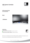
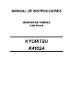
Instruction number
LTI-04-01/03/06/A
MANUFACTURER OF ELECTRONIC W EIGHING EQUIPMENT
RADWAG 26 – 600 Radom, Bracka 28 Street, POLAND
phone +48 48 38 48 800, phone/fax. +48 48 385 00 10
Sales Department +48 48 366 80 06; www.radwag.pl
March 2006
TABLE OF CONTENTS
1. INTENDED USE .... .... .... .... .... .... .... .... .... .... .... .... .... .... .... .... .... .... .... .... ..3
2. KEYBOARD .. .... .... .... .... .... .... .... .... .... .... .... .... .... .... .... .... .... .... .... .... .... ..4
3. FUNCTIONS OF KEY S... .... .... .... .... .... .... .... .... .... .... .... .... .... .... .... .... .... ..4
4. GETTING STARTED AND OPERATION. .... .... .... .... .... .... .... .... .... .... .... .... ..6
5. USER’S MENU .. .... .... .... .... .... .... .... .... .... .... .... .... .... .... .... .... .... .... .... .... ..8
6. WEIGHING ... .... .... .... .... .... .... .... .... .... .... .... .... .... .... .... .... .... .... .... .... .... 10
6.1. Select ion of the basic weight unit ... .... .... .... .... .... .... .... .... .... .... .... .... 10
6.2. Choice of weighing unit (temporary ) ... .... .... .... .... .... .... .... .... .... .... .... 12
6.3. Set ting accessibility of operating m odes . .... .... .... .... .... .... .... .... .... .... 13
7. TARING AND ZEROING. .... .... .... .... .... .... .... .... .... .... .... .... .... .... .... .... .... 16
8. OTHER PARAMETERS ... .... .... .... .... .... .... .... .... .... .... .... .... .... .... .... .... .... 17
8.1. Bac klight operation... .... .... .... .... .... .... .... .... .... .... .... .... .... .... .... .... .... 17
8.2. Bac klight operation wit h batt ery supply ... .... .... .... .... .... .... .... .... .... .... 18
8.3. “Beep” signal – react ion on pressing key s ... .... .... .... .... .... .... .... .... .... 19
8.4. Aut omatic switching of f .... .... .... .... .... .... .... .... .... .... .... .... .... .... .... .... 19
8.5. Bat tery supply lev el check ... .... .... .... .... .... .... .... .... .... .... .... .... .... .... 21
9. MAIN SETTING PARAMETERS .... .... .... .... .... .... .... .... .... .... .... .... .... .... .... 22
9.1. Filter sett ing.... .... .... .... .... .... .... .... .... .... .... .... .... .... .... .... .... .... .... .... 22
9.2. Aut ozero f unction. .... .... .... .... .... .... .... .... .... .... .... .... .... .... .... .... .... .... 23
9.3. Tare memory .. .... .... .... .... .... .... .... .... .... .... .... .... .... .... .... .... .... .... .... 24
10. SETTING OF RS 232 PARAMETERS... .... .... .... .... .... .... .... .... .... .... .... .... 25
10.1. Ty pe of printout . .... .... .... .... .... .... .... .... .... .... .... .... .... .... .... .... .... .... 26
10.2. Determining minimal mass f or some f unct ions... .... .... .... .... .... .... .... 27
10.3. RS232 baud rate .... .... .... .... .... .... .... .... .... .... .... .... .... .... .... .... .... .... 28
10.4. Setting parameters of serial transm is sion.. .... .... .... .... .... .... .... .... .... 29
11. OPERATION MODES .... .... .... .... .... .... .... .... .... .... .... .... .... .... .... .... .... .... 30
11.1. Counting pieces of the same mass .. .... .... .... .... .... .... .... .... .... .... .... 30
11.2. +/- control ref erring to the inscribed s tandard mass. .... .... .... .... .... .... 33
11.3. Control of % dev iation ref erring to the insc ribed standard m ass ... .... 36
11.3.1. Mass of st andard determ ined by its weighing. .... .... .... .... .... .... 36
11.3.2. Mass of st andard inscribed t o scale m emory . .... .... .... .... .... .... 37
11.4. Automat ic tare ... .... .... .... .... .... .... .... .... .... .... .... .... .... .... .... .... .... .... 38
11.5. Measurement max f orce on the pan – latch ... .... .... .... .... .... .... .... .... 39
12. USER’S CALIBRATION (option).. .... .... .... .... .... .... .... .... .... .... .... .... .... .... 40
12.1. Calibration. .... .... .... .... .... .... .... .... .... .... .... .... .... .... .... .... .... .... .... .... 40
12.2. St art mass adjus tment .... .... .... .... .... .... .... .... .... .... .... .... .... .... .... .... 42
13. COOPERATION WITH PRINTER.... .... .... .... .... .... .... .... .... .... .... .... .... .... 43
14. COOPERATION WITH COMPUTER .... .... .... .... .... .... .... .... .... .... .... .... .... 43
15. COMMUNICATION PROTOCOL FOR RS232 ... .... .... .... .... .... .... .... .... .... 44
15.1. Respond message f ormat ... .... .... .... .... .... .... .... .... .... .... .... .... .... .... 44
15.2. Manual printout .. .... .... .... .... .... .... .... .... .... .... .... .... .... .... .... .... .... .... 45
15.3. Continuous trans mission. .... .... .... .... .... .... .... .... .... .... .... .... .... .... .... 46
16. ERROR COMMANDS.... .... .... .... .... .... .... .... .... .... .... .... .... .... .... .... .... .... 47
17. TECHNICAL PARAMETERS... .... .... .... .... .... .... .... .... .... .... .... .... .... .... .... 47
-2 -
1. INTE NDE D USE
Platform scales are designed for fast and precise measurements of
wei ghed loads masses and direct commerci al settlements.
Tarring i n full wei ghing range enables to determine net mass of
wei ghed loads. Additional displ ay i s additional equi pment of scale.
It is to control mass of weighed load by another person.
Functions of scale:
- backlight of di splay
- level of fi ltration
- autozero function
- setting baud rate of transmi ssion
- continuous data transmission for RS 232
- automati c operation for RS 232
- print setup(stable/unstable)
- designation minimum mass for function operating
- counting pieces
- +/- mass control
- percentage deviation from standard mass
- latch of maxi mum scale indi cati on
- automati c tare
- memory of tare
- automati c scal e switch-off
- user calibration
User functions may have attri bute of accessibili ty. For this reason it
is possi ble to adjust scal e to i ndividual needs to provi de access to only
these functions which are currently needed.
Attribute determination accessibl e/i naccessibl e i s possible in user
menu and described in further part of manual .
-
Notice:
RS 232 connector is install ed in some types of scal es
optionally, on cli ent’s request. If your scale does not have this
connector, setti ng bod, rEPL, cont functions does not influence
the operation.
-3 -
2. KE YBOARD
3. FUNCTIONS OF KEYS
- swi tch on/off power suppl y (keep pressing the
button for about 1 second)
- functi on key (selection of operating mode)
Sending result of wei ghing to printer or computer
- scale zeroi ng
- scale tarri ng
Notice:
After pressing F +PRINT key functions of particular keys change for
time of programmi ng the function. Method of use is described in further
part of the manual.
-4 -
SIGNS ON DISPLAY
No
Message
Description
1.
FIL
Filteri ng level
2.
bAud
RS232 baud rate
3.
PCS
Counting pieces
4.
HiLo
+/- control i n relation to reference mass
5.
rEPL
Automatic pri ntout of di splay status
6.
StAb
Data will be printed when stable
7.
Auto
Control and correction of zero indication of scale
8.
t1
Ti me-lag switch
9.
toP
Measurement of max. force influencing weighing
pan
10.
Scale in autozero range (indi cati on = precise zero)
11.
Result of measurement is stable (ready for readout)
12.
PCS
Scale in operati ng mode counting pieces
13.
kg (g)
Scale in operati ng mode w eighing
Low level of batteries, accumulator ( scale will
switch off soon) or damaged scale adapter/supplier.
14.
15.
16.
17.
18.
Net
Scale is tarred.
+/- control i n relation to reference mass – setti ng
l ower threshol d or mass below fi rst range
+/- control in relation to reference mass: mass of
l oad between set threshold
+/- control in relation to reference mass – setting
upper threshold or mass above upper threshold.
-5 -
4. GE TTING STARTE D AND OPE RATION
-
-
-
Scal e should be unpacked and placed on even stable base far
away from heat sources. Then install the wei ghing pan and
level the scale using levelling feet of the scale and the l evel
indicator.
For l ow profile scal es – screw i n the level ling feet and level out
the scale using l evelling feet of the scale and the l evel
indicator. If this way is not suffi cient, steel washers shoul d be
put under the l evelli ng feet.
Switch on the scale usi ng ON/OFF scale (keep pressi ng the
button for about 1 second)
Now wait until the scal e test i s over and indication (equal zero)
appears:
- precise zero indi cati on
- resul t of weighing i s stabl e
kg
- scale in operating mode - weighi ng
Scale is ready to w ork
.
-6 -
Weighing for dual range scales
Switching from weighing I range to wei ghing in II range occurs
automaticall y without participation of operator (after exceeding Max I
range).
Weighi ng in II range is signalized by displ aying a pictogram i n l ower
right corner of display.
After removi ng load scale goes back to zero. Weighing i s still wi th
accuracy of II range until it shows the exact zero.
Return from weighing i n II range to wei ghing in I range can be
performed automati cal ly, after removi ng loads from the weighing pan
and entering the AUTOZERO zone – signaled by
.
Then the symbol of the second range is bei ng swi tched of and the
scale returns to weighing wi th the accuracy of the I range.
-7 -
5. US ER’S MENU
The menu is di vided into 6 basic groups. Each group has i ts indivi dual
name starti ng with the capital letter P.
Names of groups and their contents are shown below.
P1 rEAd
P1.1
P1.2
P1.3
FiL
Auto
tArF
|
|
|
2
Y ES
no
P2 Prnt
P2.1
P2.2
P2.3
P2.4
Pr_n
S_Lo
bAud
S_rS
|
|
|
|
St Ab
4800
8d1SnP
P3 Unit
P3.1
St Un
|
kg
P4 Func
P4.1
P4.2
P4.3
P4.4
P4.5
P4.6
P4.7
P4.8
FFun
Funi
Pc S
HiLo
PrcA
Prcb
At Ar
toP
|
|
|
|
|
|
|
|
ALL
Y ES
Y ES
Y ES
Y ES
Y ES
Y ES
Y ES
P5 othr
P5.1
P5.2
P5.3
P5.4
bL
bLbt
bEEP
t1
|
|
|
|
Auto
50
Y ES
Y ES
P6 CAL
P6.1
P6.2
St _u
uCAL
|
|
-8 -
5.1. Brow ning user’s menu
User moves in the menu using the scale keyboard.
5.1.1. Keyboard
+
enter to the main menu
selection of parameter a menu level or change of
acti ve parameter val ue
entering selected submenu or activation of a parameter
for a change
change confirmation
leave a function wi thout changes or move one level
higher i n the menu
5.1.2. Pow rót do funkcji w ażenia
Introduced changes in the scal e memory wi ll be saved
after return to weighing by the procedure of saving
changes.
Press several ti mes F key unti l display indi cates the
message SAv E?.
When displ ay i ndicates question press PRINT/ENTER to
confi rm changes or F – to cancel introduced changes .
After pressing an appropriate key, scal e wi ll go back to
wei ghing
Return to weighing
-9 -
6. WEIGHING
Place a load on the weighi ng pan. After reaching stability the
pi ctogram is marked, read weighing result.
6.1. Selection of the basic w eight unit
Function i s used for setting the initial uni t with which the scal e wi ll start
after switching on. Enter the submenu P3 Unit
press
units.
key several l imes. Display will indicate by turns availabl e
- 10 -
After choosing basic uni t press
. key. Chosen unit wi ll stop bli nking.
Possibilities of choice:
• When main unit i s [kg], an user can set one of the foll owing
units: [kg, lb, N] (l b i s accessible only i n non-verified scal es)
• When main unit i s [g], an user can set one of the followi ng
units: [g, ct]
Go back to w eighing using procedure of sav ing changes
(see chapter - 5.1.2. – return to weighing)
NOTICE:
Scal e after switching on will start with the newly set basi c unit.
- 11 -
6.2. Choice of w eighing unit (temporary)
Function enabl es choice of unit with whi ch mass on the pan will be
indicated. Unit will be valid until change of unit or switching on and off
the scale.
Procedure:
Press F key
After confirmation of sel ected unit, the scal e wi ll go back to weighi ng in
this unit.
Possibilities of choice:
• When main unit i s [kg], an user can set one of the foll owing
units: [kg, lb, N] (l b i s accessible only i n non-verified scal es)
• When main unit i s [g], an user can set one of the followi ng
units: [g, ct]
- 12 -
6.3. Setting accessibility of operating modes
In this group of parameters users declares functions which are to be
accessi ble for user after pressing F key.
Enter P4 Func
- 13 -
6.3.1 Setting accessibility of operating modes (for user)
Thi s function enables user to set if ,after pressing F key, all operati ng
modes wil l be accessible (ALL) or only one from the li st chosen and
used by operator.
After choosing setting press PRINT key. The program will return to
di splaying name of submenu P4.1 FFun.
- 14 -
6.3.2 Setting contents of P4.1 FFun to “ALL”
Thi s is the function to disable all modes that are not intended to use by
operators. It accel erates the access to used modes.
no – mode is disabled;
YES – mode is enabled
Return to weighing
(see - 5.1.2. – return to weighing)
- 15 -
7. TARING AND ZE ROING
In order to determine a net mass place a package of load and when
indication is stable press TARE key (mass indi cation will go back to
zero, Net symbol wi ll be displayed on the l eft side of the display).
After placing a load, the displ ay wi ll i ndicate net mass.
Tarring can be done repeatedly in full weighi ng range of the scale.
When usi ng tare functi on pay attenti on on not exceeding maximum
weighi ng range. After removing the load and the package di splay
will show indication ofl sum of tarred masses with minus sign.
Zeroing
Zeroing displ ay status is possible only i n range up to ±2% of
maximum scal e capacity. If zeroed value i s bigger than ±2% of
maximum capacity displ ay wi ll show Err 2 message.
The new zero point i s treated by the scale as the preci se zero.
Zeroing i s possible whil e stabl e status i s shown on the display.
- 16 -
8. OTHER P ARAMETERS
Users can set parameters which have i nfl uence on operation of the
scale. These parameters are included in P5 othEr e.g. backl ight and
„beep” si gnal.
Enter P5 Others submenu accordi ng to point 6.1.
The software recognizes the source of supply, (mains, battery) i and
automaticall y selects the way of backli ght operation:
- bL – for adapter supply
- bLbt – for battery supply
8.1. Backlight operation
bL
bL
bL
no – backli ght off
YES – backlight on
Auto – backlight switched off automatically if the indicati on
does not change for 10 seconds.
Return to weighing
(see - 5.1.2. – return to weighing)
NOTICE:
If result of w eighi ng doesn’t change for 10 seconds, backli ght wi ll turn
off automatical ly. Backli ght is automatically turned on when indication
on display changes.
- 17 -
8.2. Backlight operation with battery supply
Considering the readabili ty and power consumption users can change
the i ntensity of backlight from 0% to 100%. Lower backlight intensi ty is
advisable to lengthen the ti me of battery working. Whil e using battery
supply backl ight switches off automatically if the indicati on does not
change for 10 seconds.
Return to weighing
(see - 5.1.2. – return to weighing)
Notice:
The intensity of backlight influences the time of battery discharge .
- 18 -
8.3. “Beep” signal – reaction on pressing keys
bEEP
bEEP
no
YES
– si gnall ing of pressing key is di sabled
- signal ling of pressing key is enabled
Return to weighing
(see - 5.1.2. – return to weighing)
8.4. Automatic sw itching off
Thi s function is essential for economical exploi tation of battery.
The scal e wi ll switch off when (function t1 = YES) no weighi ng took
pl ace (i ndication of display didn’t change) i n 5 minutes. Thi s
function can be switched off (t1 = No ).
- 19 -
Procedure:
t1 YES
t1 No
- function is active (for battery supply)
- function is off (for buffer and power supply)
Return to weighing
(see - 5.1.2. – return to weighing)
If during operating with battery supply software detects too l ow l evel
. Thi s means that
of battery voltage, displ ay wi ll i ndicate symbol
batteries should be changed i mmediately or must be charged.
If this pictogram bli nks it means that the battery i s being charged.
Operating of indication of low battery and automatic switch off.
Low battery level signalizati on:
•
pictogram appears in the display to show low supply vol tage
on battery clamps
• after a period of time working on low battery the scale swi tches
off in order to prevent the battery from excessive di scharging.
• Battery loading is signalled by blinking the
pi ctogram.
- 20 -
8.5. Battery supply lev el check
Thi s function is to check the l evel of battery supply.
It works only if:
• Weighi ng mode i s set
• Battery supply is set in parameters
Procedure:
After displ aying the level of batteries (in per cents) the program returns
to wei ghing. The symbol
(bat low) swi tches on when the voltage
level drops to 18% of the accepted level of voltage.
- 21 -
9. MAIN SE TTING PARAMETERS
User can adjust scale to external conditions (filter range) or own
needs (autozero working, memory of tare value).
These parameters are accessible in group <P1 rEAd> and wil l help
users to adjust scale to external condi tions (vi brations, draughts) in
which scales operate.
9.1. Filter setting
Procedure:
-
using
key sel ect the value of fi ltering
OFF – Fil tering is off
1 - 4 - Fi ltering i ntensity
Return to weighing
(see - 5.1.2. – return to weighing)
NOTI CE
Filter range c an inf luence the time of s tabilization
- 22 -
9.2. Autozero function
In order to ensure precise i ndication „AUTOZERO” functi on has been
introduced. The i ntended use of this function is automatic control and
correction of zero indicati on of the scale.
When function is active comparison of resul ts takes place at assumed
time interval s. If resul ts di ffer by val ue smaller than decl ared
AUTOZERO range e.g. one di vision, scale will be zeroed
and zero indi cati on –
automaticall y, stable state wi ll be marked–
will be di splayed.
When AUTOZERO function is enabled, each result starts from precise
zero. However there are some cases where thi s function can be disturb
in measurements. It can be (e.g.) very slow load placi ng on the pan
(e.g. load pouring) i n such case correcti on system of zero indication can
al so correct i ndication of real mass of load.
Procedure:
AUTOZERO
AUTOZERO
no
– autozero off
YES - autozero on
Return to weighing
(see - 5.1.2. – return to weighing))
- 23 -
9.3. Tare memory
Thi s function is created to stores the last tare val ue in the scale
memory. It is automati cal ly displayed after a restart of the scale. Tare
value is displayed with minus sign, and displ ay i ndicates Net symbol.
Procedure:
tArF no
– function of automatic tare disabl ed
tArF YES
- functi on of automatic tare enabl ed
Return to weighing
(see - 5.1.2. – return to weighing)
- 24 -
10. S ETTING OF RS 232 P ARAME TERS
External device connected to RS 232C socket must be suppli ed
from common mains e.g. with common antishock protection
preventing from existence of potenti als difference on zero wires
and connected device.
Scheme
Transmission parameters programmed in scale:
- Speed of transmission - 2400 – 38400 bit / s
- Data bits
- 7, 8
- Stop bit
- 1, 2
- Parity control
- none, even, odd
There are three ways of sending the indi cated value through seri al
interface to an external device:
-
Manually - after pressing PRINT key
Automatically – after stabil izing of indication
Continuously – when it i s set i n parameters or by RS232
command
On request – when an external devi ce sends a request
command. See additional functions - „List of scale computer commands”
It i s possible to set conditi ons of sending present mass by RS232:
- stable – i nformation is sent after the result is stable
- non-stabile – the current value of the di splay is sent
immediately regardless i t is stabl e or not. It can be sent on
request by the RS232 or tafter pressing PRINT, it is marked
with <?> in front of the mass value.
- 25 -
10.1. Type of printout
It is possible to set different types of printouts.
Procedure
noStAb
StAb
rEPL
CntA
Cntb
– immediate pri ntout (even if not stable) – not
accessi ble in verified scales
– pri ntout of stable results
– automatic operation
– continuous transmission in a basic unit
– continuous transmission in a current unit
Return to weighing
(see - 5.1.2. – return to weighing)
- 26 -
10.2. Determining minimal mass for some functions
This program gives possibility to set functi on of automatic tare or
automatic operation.
The next tarring wi ll not be performed unl ess the measurement
(gross) i s bel ow the val ue S_Lo.
For automatic operation the next measurement i s not sent unti l
the measurement (net) drops below the i nscribed value S_Lo.
Procedure:
Return to weighing
− (see - 5.1.2. – return to weighi ng)
- 27 -
10.3. RS232 baud rate
The method of setting the baud rate:
Return to weighing
(see - 5.1.2. – return to weighing)
- 28 -
10.4. Setting parameters of serial transmission
Procedure
7d2SnP
7d1SEP
7d1SoP
8d1SnP
8d2SnP
8d1SEP
8d1SoP
-
7
7
7
8
8
8
8
bits of data;
bits of data;
bits of data;
bits of data;
bits of data;
bits of data;
bits of data;
2 stop
1 stop
1 stop
1 stop
2 stop
1 stop
1 stop
bits, no pari ty control
bit, EVEN pari ty control
bit, ODD parity control
bit, no parity control
bits, no pari ty control
bit, EVEN pari ty control
bit, ODD parity control
Return to weighing
(see - 5.1.2. – return to weighing)
- 29 -
11. OPERATION MODES
11.1. Counting pieces of the same mass
Standard solution is equi pped with opti on of counting small pi eces of
the same mass. Counting pieces does not operate with other scale
functi ons. It is possible to execute a tare function in this operating
mode i n order to tare a container val ue.
To use this option:
• enter to PIECE function.
key to start setting quantity of sample, you have a few
• press
options to chose from
- 30 -
• pressing
key to choose of value (10, 20, 50pcs. or free)
• if you want to choose one of them e.g. 20pcs press
proceed as shown in the picture
−
and
If the option FrEE was chosen, you must enter the quantity of
sample, whi ch wi ll serve to determi ne the mass of a single detail
- 31 -
−
By pressi ng TARE key you choose digit posi tion to change
−
Pressi ng ZERO you change value of digi t
•
Confirm the entered value by pressing PRINT key
The display will indicate a LoAd message – place on the pan
as many details as entered during option
•
Press PRINT key – scal e wil l indi cate quantity of sample (PCS
symbol is active)
•
add remaini ng details, displ ay wi ll i ndicate their quantity.
•
Return to weighing
• press F t wice
Notice:
If an user presses the F key when detai ls are not present on the pan,
the message -Lo- will be indi cated for a few seconds and the scal e w ill
automati call y return to wei ghing.
- 32 -
11.2. +/- control referring to the inscribed standard mass
Procedure:
• Enter the functi on.
Duri ng setti ng threshold values following cases take pl ace:
- 33 -
SET LOWER THRESHOLD
TARE – selection of the digi t to set; ZERO - selection of the di git
value; PRINT – conf irm ation of t he entered v alues
SET UPPER THRESHOLD
TARE – selection of the digi t to set; ZERO - selection of the di git
value; PRINT – conf irm ation of t he entered v alues
- 34 -
NOTICE:
If a user erroneously enters a val ue of the l ower threshold higher than
the upper one, the scale wi ll i ndicate an error message and wil l
return to w eighi ng.
Return to weighing
•
Press the F key twice
- 35 -
11.3. Control of % dev iation referring to the inscribed standard mass
Scale software enables control of devi ati on (in %) of weighed l oads
mass referri ng to the i nscribed standard mass. Mass of standard can
be determi ned by i ts weighi ng (PERC A function) or entered to the
scale memory by an user (PERC B function)
11.3.1. Mass of standard determined by its w eighing.
Procedure:
• Enter the functi on
• place an load on the pan which mass will be accepted as standard
• press PRINT to conf irm t his operat ing mode
• af ter f ew s econds t he indication 100,00% will be display ed
From t his mom ent display will not indicate mass of weighed load but dev iation
of load m ass placed on the pan ref erring to the m ass of standard (in %).
- 36 -
11.3.2. Mass of standard inscribed to scale memory
Procedure:
• Enter the functi on.
•
•
The display will show an indicat ion as abov e:
Using key s
TARE – select ion of a digit to set
ZERO
- setting the v alue of the selected digit
set val ue of mass of standard, enter it to sc ale mem ory using PRI NT
key – display will indicate: 0,00%
From t his mom ent display will not indicate the m ass of weighed load but
dev iation of the load mas s placed on the pan ref erring mass of standard (in %)
Return to weighing
•
press F t wice
- 37 -
11.4. Automatic tare
Thi s function is useful for fast net mass determinati on of wei ghed load
in case when tare value of i s different for each load. In case when the
function is active the cycle of scales operati ng looks as follows:
− press zeroing key when the pan i s empty
− place the container for pi eces
− when indi cati on is stable automatic tarring of the container mass
wi ll be performed (Net marker wil l appear in the upper part of the
displ ay)
− place a sample into the package
− displ ay wi ll i ndicate net mass of sample
− remove the sample together with the container
− displ ay wi ll i ndicate tare mass with minus sign
− place a container for the next sample. When i ndication is stable
automatic tarri ng will take place (Net marker wi ll appear i n the
upper part of the display)
− place next sampl e i nto the package
Procedure:
Resignation from function
•
press F t wice
- 38 -
11.5. Measurement max force on the pan – latch
Confirmation of choi ce of toP function i s indication of the Max
pictogram.
- appl y a force to the weighing pan. The displ ay of scale
will latch the maximum value of the force
- remove loads from the pan
- before the next measurement press the → 0←
← key
Return to weighing
•
press F t wice
- 39 -
12. USER’S CALIBRATION (option)
Confi rmati on of hi gh accuracy of weighing requires peri odical
correcting cal ibrati on factors in the scal e memory – it is adjustment
of the scale. Calibration shoul d be performed when we start
weighing or dynamic change of temperature occurs. Before starting
calibration remove loads from the pan
12.1. Calibration
Procedure
−
fol lowi ng inscriptions will appear
−
−
A new start mass is adjusted duri ng this period of time. After that
a mass of calibration weight i s shown (e.g. 3 000kg).
Put the calibration weight on the wei ghing pan and press PRINT
Process of cali bration wi ll be performed.
- 40 -
−
After completion of the process of cali bration the following
screen will appear
−
take off the weight , then the fol lowi ng sequence of screens wil l
appear.
−
return to weighing performi ng the procedure of savi ng
parameters.
Return to weighing
(see - 5.1.2. – return to weighing)
- 41 -
12.2. Start mass adjustment
If the scal e does not require the full calibration process sit i s possible to
adjust only a new start mass.
Procedure
−
the display wil l show the foll owing information
−
after the completion of the start mass adjustment the foll owing
screen will appear
- 42 -
13. COOP ERATION WITH P RINTE R
Each time the PRINT key is pressed a current mass value together
with mass uni ts is sent to RS 232 interface.
Depending on setting of STAB parameter it can be printed out with
temporary or stable value. Depending on setting of REPL
parameter, printout will be automati c or manual.
One of thermal printer in KAFKA series can cooperate wi th each
platform scales:
a) KAFKA
Only resul t of weighing wi th mass uni t can be pri nted
b) KAFKA 1/Z
This pri nter i s equipped with an internal real ti me clock.
Both date and time can be printed.
c) KAFKA SQ S
This pri nter i s equipped with an internal real ti me clock and
possi bil ity of runni ng stati stics from measurements. Statistic
contents: quantity of sampl es, sum of masses of all samples,
average value, standard deviation, variation factor, min
value, max value, difference max - min
14. COOP ERATION WITH COMPUTE R
Sendi ng wei ghing results to the computer can be done:
-
-
manually - after pressing PRINT key
in continuous way – after functi on activating or sending an
appropriate command
automatically – when the result is stable (if REPL YES and
before placing a load, the scale indi cated a value below Lo
val ue)
on demand sent from a computer – see Li st of commands
- 43 -
15. COMMUNICATION P ROTOCOL FOR RS232
Table 0-1 A set of commands for Rs232 interface
Commands
Contents
Z
Zeroing
T
Tarri ng
S
Send the stabl e resul t in basic uni t
SI
Send the resul t immediatel y in basic uni t
SU
Send the stabl e resul t in current unit
SUI
Send the resul t immediatel y in current unit
C1
Switch on continuous transmission i n basic unit
C0
Switch off continuous transmission i n basic unit
CU1
Switch on continuous transmission i n current unit
CU0
Switch off continuous transmission i n current unit
PC
Send all i mplemented commands
Each command hale to be termi nated in CR LF
15.1. Respond message format
After sending a request message you can receive:
XX_A CR LF– command accepted and in progress
XX_D CR LF -command completed (appears only after XX_A)
XX_I CR LF
– command comprehended but cannot be executed
XX _ ^ CR LF – command comprehended but time overflow error
appeared
XX _ v CR LF – command comprehended but the indi cation below
the
XX _ E CR LF – error while executing command – time limit for stable
result exceeded
XX
– command name
- 44 -
Comman
d
Spac e/
3rd
c harac ter
of
c omman
d
Stability
c haracter
s pac e
s ign
mas s
space
unit
CR
LF
Command – 1 – 3 characters
In case a command incl udes 3 characters the last character substitutes
the foll owing space. This way the length of the frame remains
unchanged.
Stabil ity character
– [space] if stabl e
[?]
if not stable
[^]
if an indication oper the range
[v]
i fan indication bel ow the range
sign
– [space] for posi tive values or [-] for negative values
mass
– 9 characters justi fied to the right
unit
– 3 characters justi fied to the left
15.2. Manual printout
Users can generate printouts manually by pressing PRINT key
Setting (see - 10.1)
If the scale is v erified the immediate printouts are blocked
(only stable results can be sent)
Frame form
1
2
3
4 -12
13
Stability
c harac ter
s pac e
s ign
mas s
s pac e
14
15
unit
16
17
18
CR
LF
Stabil ity character
– [space] if stabl e
[?]
if not stable
[^]
if an indicati on is over the range
[v]
if an indicati on is below the range
sign
[space] for positi ve values or [-] for negative val ues
mass
9 characters justified to the right
unit
3 characters justified to the left
- 45 -
15.3. Continuous transmission
The indi cator can work i n a conti nuous transmission mode. It can be
switched on or off i n parameters or usi ng RS232 commands
Continuous transmission setting
(see - 10.1)
−
−
−
−
C1 CR LF – Swi tch on conti nuous transmi ssion in basic unit
C0 CR LF – Swi tch off conti nuous transmi ssion in basic unit
CU1 CR LF – Swi tch on conti nuous transmi ssion i n current unit
CU0 CR LF – Swi tch off conti nuous transmi ssion i n current unit
1
2
3
4
5
6
7-15
16
S
I
space
Stability
c harac ter
s pac e
s ign
mas s
s pac e
17
18
unit
19
20
21
CR
LF
Stabil ity character
– [space] i f stable
[?]
if not stable
[^]
if an indicati on over the range
[v]
if an indicati on below the range
sign
[space] for positi ve values or [-] for negative val ues
mass
9 characters justified to the right
unit
3 characters justified to the left
- 46 -
16. E RROR COMMANDS
"Err2" - value beyond the zero range
"Err3" - value beyond the tare range
„Err4” – Cal ibrati on mass or start mass beyond the acceptable range
(±1% for weight, ±10 for start mass).
„Err5” – Mass of a singl e piece l ower than the scale di vision.
"Err7" – power down time was to short (should be over 3s)
"Err8" – operati on time exceeded tarring/zeroi ng
„NULL” – zero value from the AD converter
„FULL2” – measurement range overflow
„LH” – start mass error, the mass on the wei ghing platform is beyond
the acceptable range ±10 of start mass.
17. TE CHNICAL PARAMETERS
W PT
3C1
W PT
6C1
W PT
10C1
W PT
5C
W PT
12C
W PT
24C
W PT
30/60C
Maximum capacity
3kg
6kg
10kg
5kg
12kg
24kg
60kg
Minimum capacity
1g
2g
2g
4g
4g
10
10g
Reading Division
0,05g
0,1g
0,1g
0,1g
0,2g
0,5g
1/2g
Tare range
- 3kg
-6kg
-10kg
-5kg
-12kg
-24kg
-60kg
Type *
Operating temperature
range
-10˚C ÷ 40˚C
230 V AC / 11 V AC
Power supply
Pan size
Option: internal r echarg eable
battery pack 12 V
Standard 6xR6 alkaline batteries
165 x 165mm
250 x 300mm
RS 232 inter face
standar d
* - sc ales with internal battery pac k are marked as WPT xx/CA
Inst ruction number
LTI-04-01/03/ 06/A
- 47 -
- 48 -
MA NUFACTURER
OF ELECTRONIC WEIGHING EQUIPMENT
RADWA G 26 – 600 Radom
Bracka 28 Street
POLAND
Central phone +48 48 38 48 800
phone/fax. + 48 48 385 00 10
Sales Department + 48 48 366 80 06
w w w .radw ag.pl