1
S-COM 6K
MICROPROCESSOR REPEATER CONTROLLER
OWNER'S MANUAL
V1.02
03-16-91
(V2.0 upgrade in back)
S-COM Industries
P.O. Box 1546
LaPorte, CO 80535-1546
U.S.A.
970-416-6505 Phone
970-419-3222 Fax
www.scomcontrollers.com
IMPORTANT!
1.
This product uses CMOS integrated circuits and other components that can be damaged by
static electricity. Be sure that you are properly and safely grounded, and are working at a
static-free workstation, when handling these components.
2.
This product uses a lithium battery to provide power to the memory system when main
power is interrupted. This lithium battery is a primary cell. Do not attempt to recharge it!
3.
The pin designations of the DB25 connector in the 6K are slightly different than the pin
designations of the DB25 connector in the 5K. Specifically, pins 16 and 18 are active
signals in the 6K; these pins are connected to ground in the 5K. Be sure you have checked
your cable and removed connections from pins 16 and 18 if you are replacing a 5K
controller with a 6K controller!
6K V1.02 03-16-91
1
DESCRIPTION
1.
INTRODUCTION
The S-COM 6K is a high-quality, compact, microprocessor-based repeater controller
intended for use in amateur radio and commercial radio installations. Incorporating
advanced hardware and software designs, the 6K provides most-often-needed control
functions and powerful new features not found in any comparable-cost controller.
The 6K is fully remotely programmable with DTMF commands via the telephone or via the
receiver ports, thus eliminating the inconvenience of returning EPROMs, microcontroller
ICs, and PC boards to the factory for reprogramming. No jumpers or diodes are needed for
programming. Data is retained in non-volatile memory, ensuring that no information is lost
during power outages . . . making extra trips to the repeater site unnecessary.
2.
STANDARD FEATURES
A.
HARDWARE
a.
Configuration
The standard 6K controller package consists of a Main Board and a Telephone Interface
Module mounted in a rackmount cabinet. A set of mating connectors and a manual
complete the basic package.
b.
Cabinet
The cabinet provides mounting for the Main Board, the Telephone Interface Module Board,
and up to two optional Audio Delay Module Boards. The cabinet can be installed in a
standard 19" wide equipment rack. The cabinet is constructed from three basic parts: An
iridite-plated chassis box, an iridite-plated chassis cover, and a black anodized front panel.
The cabinet occupies 1-3/4" of vertical rack height, and measures about 7" deep. This
shallow cabinet may be installed in any rack, including the slim Motorola rack cabinets.
c.
Main Board
The 6K Main Board measures 6" deep by 8" wide, and can operate as a stand-alone
controller. The digital portion of the board contains the microprocessor, memory, and logic
input/output circuits. The analog portion contains the DTMF encoder/decoder, audio
crosspoint switch, tone synthesis, and audio interface circuits. Two connectors, a DB25
female and a 2.5-mm DC power jack, are mounted on the Main Board. These connectors
protrude through cutouts in the rear of the cabinet, allowing the interior of the cabinet to be
free of wiring harnesses.
d.
Telephone Interface Module
The Telephone Interface Module (TIM) is constructed on a 3" by 6" PC board, and adds
Autopatch, Reverse Patch, and Phone Line Control capabilities to the 6K Main Board. It is
registered with the FCC under Part 68 Rules, eliminating the need for a separate telephone
6K V1.02 03-16-91
2
coupler. Transient protection and RFI filtering is provided. The all solid-state design of the
TIM eliminates the possibility of mechanical relay failure, and the built-in electronic hybrid
allows both half-duplex and full-duplex autopatch calls. The TIM supports both regenerated
DTMF dialing and 10/20 PPS rotary dialing.
B.
SOFTWARE
a.
CW Identifier
The software CW Identifier stores remotely-programmable multiple call signs with ID Tail
Messages. The interval between identifications is also programmable. The CW is internally
mixed with repeat audio. The ID'er is "polite," which means that it attempts to identify only
during breaks between transmissions.
b.
CW Messages and Paging Formats
Most of the CW messages are remotely programmable. CW pitch and speed is
programmable, and can even be changed within a message. The CW character set
includes alphanumerics, punctuation, and a large library of "beeps." The CW amplitude
level is set with a potentiometer.
The 6K supports single-tone (group call), two-tone sequential, 5/6-tone, and DTMF paging
formats. Separate pots allow adjustment of tone paging and DTMF paging. Pages may be
stacked for convenient call-ups of ARES members, weather spotters, DX Club members,
on-the-air meetings, and so on.
c.
Timers
All timers in the 6K are derived from the microprocessor's crystal-controlled clock circuit for
improved accuracy over other methods. Most timers are remotely programmable, including
the Courtesy Timer, Dropout Timer, Timeout timer, Autopatch Timer, etc.
d.
Repeater Characteristics
The character of a repeater can be varied by choosing distinctive Courtesy Messages,
Timeout Messages, Dropout Messages, and their associated timers. The repeater can be
placed into one of several access modes, or disabled. These characteristics can be
changed by command or by a transition detected by one of the logic inputs.
e.
Clock and Calendar
A CW readout of the current time and date can be commanded. The clock can be read in
either 12-hour or 24-hour format. An additional command is used to adjust the accuracy of
the clock. (Power must be provided continuously to the controller for the clock and calendar
to stay set).
f.
Logic Inputs and Outputs
Logic inputs are used to detect a change of state in monitored devices at the repeater site.
Logic outputs are manipulated by command to pulse or latch a controlled device at the site.
6K V1.02 03-16-91
3
g.
Command Language
Commands are given to the 6K with an easy-to-use DTMF language. Security is enhanced
with a password system, as well as programmable restrictions on DTMF decode operation.
A library of Macros may be defined for the repeater's users. Macros may be created,
deleted, renamed, and modified at any time by authorized control operators.
3.
OPTIONAL FEATURES
Audio Delay Module
The Audio Delay Module (model ADM/K) is constructed on a 2.1" by 2.7" PC board. It
removes squelch noise bursts and DTMF tone bursts from received audio. Up to two ADMs
may be installed in the 6K cabinet, one each for receiver #1 and receiver #2. The ADM will
delay audio in the range of 50 to 150 milliseconds, adjustable via a potentiometer.
6K V1.02 03-16-91
4
LIMITED WARRANTY
This warranty gives you specific legal rights, and you may also have other rights which vary from
state to state.
COVERAGE
Except as specified below, this warranty covers all defects in material and workmanship in this
product. The following are not covered by the warranty:
1.
Damage to, or deterioration of, the external cabinet.
2.
Damage resulting from lightning, accident, misuse, abuse, or neglect.
3.
Damage resulting from failure to follow instructions contained in your owner's
manual.
4.
Damage occurring during shipment of the product (claims must be presented to the
carriers).
5.
Damage resulting from repair or attempted repair by anyone other than S-COM
Industries.
6.
Damage resulting from causes other than product defects, including lack of
technical skill, competence, or experience of the user.
7.
Damage to any unit which has been altered or on which the serial number has been
defaced, modified or removed.
ENFORCEMENT
This warranty may be enforced only by the original purchaser.
LENGTH OF WARRANTY
For both labor and parts, this warranty will be effective for one (1) year from the date of original
purchase.
WHAT WE WILL PAY FOR
We will pay all labor and material expenses for items covered by the warranty. Payment of shipping
charges is discussed in the next section of the warranty.
HOW YOU CAN GET WARRANTY SERVICE
Your unit must be serviced by S-COM's Service Department. Please do not return your unit to
the factory without prior authorization. You must pay any shipping charges if it is necessary to
ship the product to service. However, if the necessary repairs are covered by the warranty, we will
pay the return shipping charges to any destination within the U.S. Whenever warranty service is
6K V1.02 03-16-91
5
required, you must present the original dated invoice or a photocopy.
S-COM's liability for any defective products is limited to repair or replacement of the product, at SCOM's option.
S-COM reserves the right to make any changes in design or additions to, or improvements in, its
products without any obligation to install such additions or improvements in equipment previously
sold. S-COM further reserves the right to replace defective parts under warranty with different or
improved parts.
This warranty is expressly in lieu of all other warranties, expressed or implied, including any implied
warranty of merchantability or fitness, and of all other obligations of liabilities on the part of S-COM.
6K V1.02 03-16-91
6
THEORY OF OPERATION
1.
INTRODUCTION
Great care was taken in the design of your controller to make it "installer-friendly." Audio and logical
interfaces were made as universal in nature as possible, so that a minimum of external hardware is
needed to complete the installation. Although the controller's "engine" is a powerful
microprocessor, the command language is designed to be easy-to-learn and flexible.
2.
PRE-PROGRAMMING (DEFAULTS)
The controller needs to know your repeater's call sign for its identifier; you must also tell it your
choice of courtesy message, timeout timer, and so on.
You can program the controller on your workbench with an external DTMF pad and other devices to
simulate the repeater. Or, you can install the controller in your repeater and program it through one
of the receivers or the phone line.
To make the installation easier, the controller comes "pre-programmed" with certain default
information stored in its non-volatile memory. When you have finished the installation, you may
overwrite this default information by entering DTMF commands. If it ever becomes necessary to
force the controller into its original default condition again, you can accomplish this by using the
initialize pushbutton and a power-up sequence (the procedure is explained later). This procedure
causes the microprocessor to read default information from the EPROM and write it over the old
information stored in the non-volatile memory.
3.
POWER REQUIREMENTS
Your controller has only a modest power requirement, which can be supplied by the repeater's own
12-volt power supply in most cases.
The controller's Main Board and Telephone Interface Module together require 12 to 15 volts DC at
less than 100mA. (Do not exceed 15 VDC or damage may occur). The controller does not require
regulated power, since it contains internal voltage regulators to create the necessary 10-volt DC
audio supply and the 5-volt DC digital supply. A third supply of 4.5 volts DC is created from the 10V
audio supply, and is used as the audio section's bias voltage.
4.
REPEATER INTERFACING
Besides the power supply, the controller requires a minimum of four connections to the repeater.
They are: (1) Receiver COR; (2) Receiver Audio; (3) Transmitter PTT; and (4) Transmitter Audio.
You must eliminate any paths that might bypass the controller. In other words, there must not be
any connection from receiver audio to transmitter audio or from receiver COR to transmitter PTT
except through the controller. Otherwise, the controller will not be able to fully take charge of
repeater control functions.
If you require subaudible tone operation, you may connect a CTCSS decoder's output to the
controller. The controller will then allow you to switch the repeater from carrier operation to one of
6K V1.02 03-16-91
7
several CTCSS modes via DTMF commands.
5.
2nd RECEIVER INTERFACING
An additional receiver can be interfaced to your controller, which can act as either a link receiver or
a control receiver. If a 2nd receiver is used, the controller requires a minimum of two additional
connections. They are: (1) Receiver COR; and (2) Receiver Audio.
If you require subaudible tone operation for the 2nd receiver, you may connect a CTCSS decoder's
output to the proper input on the controller.
NOTE: The two Receiver COR inputs, the two CTCSS Decoder inputs, and the Transmitter PTT
output each has an associated dip switch on the Main Board. These switches are used to invert, or
not invert, the appropriate signal. This means that the controller can accommodate either lowactive or high-active signals.
6.
EXTERNAL DEVICE INTERFACING
The controller has three Logic Inputs, each of which can monitor the state (ON or OFF) of an
external device at the repeater site. Since you can program the controller to detect either a low-tohigh transition or a high-to-low transition (or both), there is no need for the above-mentioned "invert"
switches on these inputs.
You can monitor such sensors as power failure, a high-temperature detector, a high-water detector,
or an intrusion alarm.
The controller also has three Logic Outputs, each of which can control (ON or OFF) an external
device at the repeater site. Power MOSFETs are used as the switching devices, which are
connected in an open-drain configuration (similar to transistors wired in an open-collector
configuration).
Each output can sink 75mA when ON and withstand 40V when OFF. All three outputs are
protected from transient damage.
7.
AUDIO GATING
The controller uses an 8 by 12 analog crosspoint switch IC for audio gating. This IC operates under
instructions from the microprocessor. Since all audio sources (receivers, tone generators, and the
landline) are fed into the crosspoint switch, and since all audio loads (transmitter, tone decoder, and
landline) are driven from the crosspoint switch, the controller's audio control flexibility far exceeds
simpler designs.
8.
TONE GENERATION
CW and paging tones are generated as square waves by the HD6340 Programmable Timer IC.
These square waves are shaped by a transconductance amp stage to reduce the "thumping"
characteristic heard on CW messages. (This thumping effect is caused by the DC component in
the square wave pulse train). The tone is then filtered by a 6th-order, switched-capacitor, lowpass
stage to yield sine waves. The filter is under microprocessor control and tracks the tone frequency.
The result is a constant-amplitude sine wave tone that can be programmed to any desired
6K V1.02 03-16-91
8
frequency in the range of 100 to 3000Hz, with an accuracy of a few Hertz. CW amplitude and
paging amplitude are separately adjustable with pots.
DTMF characters are generated via the encoder portion of the MT8880 DTMF Transceiver IC.
DTMF paging amplitude is pot-adjustable. DTMF dialing amplitude is not adjustable, and is fixed at
the level set by FCC Part 68 regulations.
9.
MEMORY PROTECTION
The controller contains circuitry to protect the data stored in RAM and maintain the data during
power outages. A DS1210 IC monitors the 5-volt logic supply; when it detects an out-of-tolerance
condition, the IC disables the RAM's chip-enable input. It switches the RAM's Vcc input from the
logic supply to the lithium battery when the logic supply falls too low to maintain data integrity. The
lithium battery has a lifetime of over 5 years (10 years if kept at room temperature), since the
amount of current drawn by the RAM is very low under backup conditions (a few microamperes).
10.
VOLTAGE MONITOR AND WATCHDOG TIMER
The controller contains circuitry to properly start the microprocessor when power is applied, to stop
the microprocessor when power fails, and to restart the microprocessor if it gets into a runaway
condition from a spike or transient.
A DS1232 IC monitors the 5-volt logic supply and asserts the microprocessor's reset input when the
supply is out of tolerance. This method is superior to simple R/C reset circuits, which may not
properly reset the CPU after voltage sags (brown-outs). The reset signal that is generated by the
DS1232 drives not only the microprocessor but also other ICs to ensure that the controlled loads
will be turned off, and that a graceful power-down sequence will be observed.
The DS1232 also monitors a software-generated "watchdog" signal. This signal is created at
intervals by the execution of the microprocessor's software program. If the CPU fails to execute the
program correctly, the watchdog signal will not be generated. The DS1232 will time out in less than
one second if it does not receive the watchdog signal, and it will force the microprocessor to restart
the program.
6K V1.02 03-16-91
9
INSTALLATION
1.
INTRODUCTION
You will need to prepare either one or two cables for your 6K controller. One cable is for DC power,
and is terminated with the 2.5mm power plug provided. Since DC power may be supplied to the 6K
via the other cable if desired, this first cable is optional. The 2.5mm power jack is retained in the 6K
for the benefit of customers who are upgrading from existing 5K installations.
The other cable is for repeater connections, logic inputs and outputs, and so on. It is terminated
with the DB25P 25-pin plug provided.
This section of the manual describes the proper connections to be made between your controller
and your repeater equipment. It also describes the proper way to make the necessary audio level
adjustment.
6K V1.02 03-16-91
10
2.
RECEIVER #1 (REPEATER RECEIVER) COR
Your 6K controller requires a logic signal, generated by your repeater receiver, which becomes
active when an incoming carrier is detected. This logic signal is usually called "COR" (Carrier
Operated Relay) or "COS" (Carrier Operated Switch), and is usually generated by the receiver's
noise-operated squelch circuitry. Some receivers don't have an external COR or COS connection
but do have a "channel busy" LED indicator, which works similarly.
At this point in our discussion, it is not important whether the COR signal is "low active" or "high
active" (that is, whether the signal goes to a logic low condition or a logic high condition upon carrier
detection), since the controller has sense-reversal DIP switches on the Main Board. These
switches are discussed later.
The get a better understanding of how to interface your particular COR signal to the controller, let's
examine the controller's COR input circuit. It's a general-purpose input circuit consisting of NPN
transistor Q1C and a set of three resistors. (Q1 is actually a DIP package containing four 2N3904type transistors. R11 is a DIP package containing seven separate 10K resistors. R12 is a SIP
package containing seven 4.7K resistors with one side common.) Resistor R11F and the resistor
on pin 7 of R12 together form a roughly three-to-one voltage divider. Q1C requires about 0.7VDC
to turn on. Therefore, the COR input voltage threshold is about 3 X 0.7V = 2.1V. Your receiver's
COR driver must be capable of generating a signal that swings above and below this 2V threshold
as an incoming carrier is applied and removed, or it must have an "open-collector" type driver.
The third resistor from the group mentioned above is R13 (4.7K). R13 is a "pullup" resistor, and it's
connected between the COR Input pin and the controller's +5V supply. The purpose of this pullup
resistor is to provide input current for transistor Q1C in installations where the COR driver is an
open-collector transistor or a pair of relay contacts ("dry" switching).
Now let's get down to specific interfaces. If your receiver's COR provides a pair of relay contacts to
indicate carrier detection, then connect one contact to the controller's COR input and connect the
other contact to ground.
If your receiver's COR provides an open-collector transistor or open-drain MOSFET, then connect
your COR output directly to the controller's COR input.
Incidentally, note that some open-collector circuits will not pull down an input circuit all the way to
ground (0V). This is normal. When OFF, these drivers are open (high impedance). When ON, the
transistor driver will pull down to a few tenths of a volt above ground. If a Darlington transistor is
used, the output is even higher above ground because of the Darlington's higher saturation voltage.
If the controller were designed with a low-threshold COR input, it is possible for such driver circuits
to keep the COR input "high" permanently. Remember that the 6K uses a voltage divider to raise
the minimum threshold of the COR Input from 0.7V to 2.1V. As long as the receiver's COR output
pulls down below 2V, the COR input will operate properly.
If your receiver's COR circuit sources a voltage from a logic gate or op amp comparator, then you
may need to disconnect the COR Input's pullup resistor. Otherwise, it may interfere with the
operation of the receiver COR by trying to pull it to +5V. You can check your installation by making
the connection between the receiver COR output and the 6K COR input, then measuring the
voltage at the COR input pin with both the receiver and controller powered up. If the voltage swings
above and below the 2V threshold upon carrier detection, no problem exists. If the receiver COR
6K V1.02 03-16-91
11
voltage is normally higher than 5V and is pulled down by the controller, or if the receiver COR
cannot pull down the input below 2V, then you should clip one lead of the pullup resistor and lift it
from the board to prevent its making contact.
The 6K's Repeater Receiver COR input is pin 6 of J2.
The last step is to determine the "sense" of your receiver's COR signal. Does the COR signal go
"low" or "high" when an incoming carrier is detected? If the COR output goes "low" when a carrier
is applied and returns "high" when the carrier is removed, then place dip switch #1 (part of S2) in
the ON, (closed) position. If, however, the COR output goes "high" when a carrier is applied and
returns "low" when the carrier is removed, then place dip switch #1 in the OFF (open) position.
6K V1.02 03-16-91
12
3.
REPEATER TRANSMITTER PTT
Your transmitter requires a "PTT" (Push-to-Talk) signal from the controller. When this signal
becomes active, the transmitter will key (transmit). At this point, it is unimportant whether your
transmitter's PTT input is "low active" or "high active", since the controller has sense-reversal
dipswitches (discussed later). Your transmitter’s PTT input should be connected to pin 10 of J2.
To get a better idea of how to interface your particular PTT input to the controller, we'll examine the
controller's PTT output circuit. This circuit consists of a power MOSFET connected as an opendrain driver, plus a transient suppressor connected between the output and ground. The
suppressor removes transients above about 30V, thereby protecting the MOSFET. The MOSFET
is a large (8 Amp) device in a TO-220 package, but it was not selected for its high current capability.
Rather, it was used because of its low ON resistance (less than 1 ohm), making it a nearly perfect
switch.
The MOSFET's drain is connected to the PTT output, and its source is grounded. When turned on,
the MOSFET appears to be a very low resistance between the output and ground. When turned
off, the MOSFET appears to be a very high impedance, isolating the output from ground. Because
of these characteristics, the PTT circuit can control transmitters with a variety of PTT inputs, from
TTL-logic-compatible to large DC relay coils.
Some transmitters, including models made by Hamtronics, MELCO (Maggiore Electronic
Laboratory), and RCA (500- and 700-series), use a powered PTT input arrangement, and cannot
be keyed by an open-drain driver. These transmitters require a positive voltage to be sourced into
their PTT inputs to key; removing the voltage unkeys the transmitter. The current requirement can
be substantial.
A simple outboard circuit can be placed between the controller's PTT output and the transmitter's
PTT input to satisfy these requirements. Connect a large PNP transistor so that its emitter goes to
the transmitter's +12V supply, its collector goes to the transmitter's PTT input, and its base goes to
the controller's PTT output through a 2K resistor (important). Connect a 4.7K resistor across the
PNP transistor's base and emitter. If the transmitter draws little current through its PTT (500mA or
less), you can use a 2N2904. If the transmitter draws 1 Amp or less, use a TIP30. When using this
outboard circuit, place dipswitch #5 (part of S2) in the ON (closed) position. Skip the next
paragraphs detailing dipswitch #5.
If you are building the outboard circuit described previously, you will need to place the PTT
dipswitch in the ON position.
If you are driving your transmitter PTT directly from the controller, you must determine the "sense"
of your transmitter's PTT input circuit. Does the transmitter key when the PTT input is driven "low,"
or does it key when the PTT input is driven "high?" (The majority of transmitters key when the PTT
input is driven low).
If your transmitter keys when the PTT input is low, and unkeys when the PTT input is high (open
circuit), then place dipswitch #5 (labeled "PTT", it's part of S2) in the ON (closed) position.
If, however, your transmitter keys when the PTT input is high (open circuit), and unkeys when the
PTT input is low, then place dipswitch #5 in the OFF (open) position.
6K V1.02 03-16-91
13
4.
RECEIVER #1 (REPEATER RECEIVER) AUDIO
The controller requires audio from your repeater receiver, which should be connected to pin 13 of
J2.
To get a better idea of how to interface your particular receiver's audio output to the controller, let's
examine the controller's Receiver #1 audio input circuit.
This circuit consists of op amp U22D connected as an AC-coupled inverting amplifier with two
feedback resistors and one feedback capacitor. A 50K pot, R75, serves as a level-adjust pot for the
audio going into the op amp. The input impedance of this circuit depends upon the pot setting, but
will be 14K ohms or greater.
The best place to get receiver audio is the output of the receiver's first audio preamp stage (usually
the stage that follows the discriminator). This point is sometimes available at the "high" end of the
volume control pot. The preamp stage usually provides flat (de-emphasized) audio, and the low
impedance driving circuit (op amp or emitter-follower amplifier) can generate high-level audio while
driving the capacitance of shielded cable. Don't tap into the wiper of the volume control pot, since
accidental adjustment of the volume control will affect the repeat level. Tapping into the speaker
driver as an audio source is discouraged, for the same reason. Also, speaker audio contains more
distortion than audio from earlier stages.
The controller works best when driven with flat (de-emphasized) audio at a level of 700 mV rms (2
V peak-to-peak). If you provide this level, the controller's RX1 pot (R75) will be in the midrange
position and optimum audio will be fed to the internal circuits. You can adjust the RX1 pot to
accommodate other audio input levels. The controller's input acceptance range, as shipped from
the factory, is 200mV rms (0.5 V p-p) to 2 V rms (5.6 V p-p).
If your receiver's audio output level is below 200mV, you can increase the gain of the controller's
input by cutting a resistor. Feedback resistor R24 (100K) has one lead marked with a circled letter
"A" on the PC board. You may cut this lead and lift the resistor to increase the gain by 3. The new
input acceptance range will be 70 mV rms (0.2 V p-p) to 700 mV rms (2 V p-p). The midrange
position of the RX1 pot will now correspond to 250 mV rms (0.7 p-p).
Some repeater owners will prefer to drive the controller with pre-emphasized audio directly from the
receiver's discriminator. The controller must then de-emphasize the audio so that the audio feeding
the DTMF decoder, phone line, etc. is flat. To accomplish de-emphasis, the controller's RX1 op
amp stage must be modified to provide a -6 dB/octave rolloff response. A simple way to do this is
to replace capacitor C45 (47 pF) with a 0.01 uF if the factory gain is used. Replace C45 with a
0.0047 uF if the triple-gain modification has been done. Note that using this larger capacitor will
decrease the op amp's gain at increasing audio frequencies; you may need to make the increasedgain modification to offset the loss created by the de-emphasis capacitor.
After you have completed the repeater receiver audio interfacing, check the audio level at pin 14 of
U22D. This is the output of the RX1 op amp. You should read about 700mV rms (2 V p-p) of audio
when the receiver is fed a fully-deviated 1 KHz sine wave tone from a service monitor.
6K V1.02 03-16-91
14
5.
REPEATER TRANSMITTER AUDIO
Your transmitter will require audio from the controller. Connect the transmitter's audio input to pin
11 of the J2 connector on the controller.
To get a better idea of how to interface your particular transmitter's audio input to the controller's
audio output, let's examine the circuit used in the controller to drive the Transmitter Audio Output.
This circuit consists of two cascaded op amp stages. The first op amp, U23D, is wired as an audio
summer (mixer) and has three inputs from the audio crosspoint switch, U27. (The controller's
software program can switch audio sources into these mixed inputs. One input would carry repeat
audio, for example, while another would carry the CW ID tones).
The second op amp, U23A, is used as an audio driver. The output impedance of this stage is 600
ohms.
A 50k pot, R80, is connected between the two op amp stages and serves as the master gain pot for
all transmitter audio.
The audio voltage that the driver develops across the transmitter audio input depends upon the load
impedance presented by the transmitter's audio input. If the transmitter presents a load of 10K
ohms or greater, the controller's audio output level will be adjustable from 200 mV rms (0.5 V p-p) to
2.4 V rms (6.7 p-p). If the transmitter presents a load of 600 ohms, the controller's audio output
level will be adjustable from 100 mV rms (0.3 p-p) to 1.2 V rms (3.4 V p-p). Note that in most 600ohms systems, the nominal level is 0 dBm (775 mV rms). This would correspond to the 85%
clockwise position of pot R80.
In the above discussion, the lower voltage level corresponds to the 10% clockwise pot position.
The higher voltage level corresponds to the 100% clockwise pot position.
If you are driving the microphone input, or some other low-level (sensitive) input stage in your
transmitter, you will probably have to reduce the gain of the controller's audio driver stage. This can
be accomplished by cutting a resistor. Resistor R59 (27K) is an input resistor to the second op
amp, and has one lead marked with a circled letter "C" on the PC board. You may cut this lead and
lift the resistor to decrease the gain by a factor of about 4. This modification decreases all audio
sent to the transmitter.
If the transmitter presents a load of 10K ohms or greater, the controller's new audio output level will
be adjustable from 55 mV rms (0.2 V p-p) to 580 mV rms (1.6 V p-p). If the transmitter presents a
load of 600 ohms, the controller's audio output level will be adjustable from 27 mV rms (0.1 V p-p)
to 290 mV rms (0.8 V p-p).
As before, the lower voltage level corresponds to the 10% clockwise pot position. The higher
voltage level corresponds to the 100% clockwise pot position.
Although it is always a good idea to use shielded cable between the controller's audio connections
and the repeater's audio connections, it is especially important to do so when driving sensitive
microphone inputs in transmitters.
6K V1.02 03-16-91
15
6.
REPEATER CTCSS DECODER
CTCSS, or Continuous Tone-Controlled Squelch System, is a convenient problem solver for users
and owners in many parts of the country where the bands are overcrowded with repeaters and RFI.
In addition, your controller allows CTCSS to be required as a qualifier for entering DTMF
commands, thus increasing the security of the repeater system.
Well-known trademarked names for CTCSS include "PL" and "Private Line" (Motorola), "Channel
Guard" (General Electric), and "Call Guard" (Johnson). Your repeater may already have a CTCSS
decoder built in, or you may wish to install one of the add-on boards readily available from a
number of sources. A good example is the TS-32P from Communications Specialists, Inc., of
Orange, CA (telephone 1-800-854-0547). The TS-32P is crystal-controlled for stability, and allows
dipswitch selection of one of 32 CTCSS tone frequencies.
The CTCSS decoder should be installed in your repeater receiver following the instructions
provided by the decoder manufacturer. You will need to connect the decoder's audio input directly
to the receiver's discriminator output. The decoder provides a logic output, usually an opencollector transistor driver, which goes either "low" or "high" upon detection of CTCSS. This signal
should be connected to pin 4 of the controller's J2 connector.
The controller's CTCSS Decoder input circuitry is designed exactly like the RX1 COR input. The
transistor in this case is Q2A, the voltage divider is made up of R11B and the resistor on pin 4 of
R12, and the pullup resistor is R15. You may wish to refer back to the "RECEIVER #1 COR"
section of this manual for a discussion of the hardware design of the input circuit.
To check your CTCSS decoder interface, power up your receiver, CTCSS decoder, and the
controller. Measure the voltage at pin 4 of J2. This voltage must swing above the 2.1 V threshold
as the incoming CTCSS tone is applied and removed.
You must also determine the "sense" of your CTCSS decoder output. Does the output go "low" or
"high" when the correct CTCSS tone is received? If the output goes "low" when the tone is
detected and returns "high" when the tone is removed, then place dip switch #3 (part of S2) in the
ON (closed) position. If, however, the output goes "high" when the tone is detected and returns
"Low" when the tone is removed, then place dip switch #3 in the OFF (open) position.
6K V1.02 03-16-91
16
7.
RECEIVER #2 (CONTROL/LINK RECEIVER) COR
Your controller can be interfaced to a second receiver, if desired. This receiver can serve a number
of applications, depending on your needs. Paths ca be "set up" or "knocked down" between
Receiver #2 and three devices: The transmitter, the DTMF decoder, and the phone line. Path
control is done by DTMF commands. Allow a path between RX2 and the transmitter, and you now
have a link receiver. Allow a path between RX2 and the DTMF decoder, and you now have a
control receiver.
If you decide to add a second receiver, the controller will require a COR signal from it. Feed the
COR into pin 5 of J2.
The controller's RX2 COR input circuitry is designed exactly like the RX1 COR input. The transistor
in this case is Q2D, the voltage divider is made up of R11C and the resistor on pin 5 of R12, and
the pullup resistor is R14. You may wish to refer back to the "RECEIVER #1 COR" section of this
manual for a discussion of the hardware design of the input circuit.
To check your Receiver #2 COR interface, power up the receiver and the controller. Measure the
voltage at pin 5 of J2. This voltage must swing above and below the 2.1 V threshold as the
incoming carrier is applied and removed.
You must also determine the "sense" of your receiver #2 COR output. Does the output go "low" or
"high" when a carrier is detected? If the output goes "low" when the carrier is detected and returns
"high" when the carrier is removed, then place dip switch #2 in the ON (closed) position. If,
however, the output goes "high" when the carrier is detected and returns "low" when the carrier is
removed, then place dip switch #2 in the OFF (open) position.
IMPORTANT: If you are not using a second receiver, be sure dip switch #2 is in the ON (closed)
position. This configures the RX2 COR input for a low-active COR signal. The pullup resistor on
this input will hold the input high, thus making sure the controller does not see activity on this input.
6K V1.02 03-16-91
17
8.
RECEIVER #2 (CONTROL/LINK RECEIVER) AUDIO
If you decide to add a second receiver, the controller will require audio from it. RX2 Audio should
be connected to pin 12 of the controller's J2 connector.
The controller's RX2 Audio input circuitry is designed exactly like the RX1 Audio input. The op amp
in this case is U22C, and the level adjust pot is R76. The feedback resistor labeled R27 (100K) has
a circled letter "B" near one lead on the PC board. You may cut this lead and lift the resistor to
increase the gain by a factor of 3. If you are driving the RX2 audio input with pre-emphasized
audio, replace C48 (47 pF) with a 0.01 uF if factory gain is used. Replace C48 with a 0.0047 uF if
the increased gain modification has been done. You may wish to refer back to the "RECEIVER #1
AUDIO" section of this manual for a discussion of the hardware design of the audio input circuit.
After you have completed the Receiver #2 audio interfacing, power up both the receiver and the
controller. Check the audio level at pin 8 of U22C. The level should be about 700 mV rms (2 V p-p)
of audio when the receiver is fed a fully-deviated 1KHz sine wave tone from a service monitor.
6K V1.02 03-16-91
18
9.
RECEIVER #2 (CONTROL/LINK RECEIVER) CTCSS DECODER
If you decide to add a second receiver, you have the option of adding a CTCSS decoder to it. After
installing the decoder into the receiver, connect the decoder's logic output to pin 16 of the
controller's J2 connector.
The controller's RX2 CTCSS Decoder input circuitry is designed exactly like the RX1 COR input.
The transistor in this case is Q1A, the voltage divider is made up of R11a and the resistor on pin 2
of R12, and the pullup resistor is R16. You may wish to refer back to the "RECEIVER #1 COR"
section of this manual for a discussion of the hardware design of the input circuit.
To check your RX2 CTCSS decoder interface, power up the second receiver, its CTCSS decoder,
and the controller. Measure the voltage at pin 16 of J2. This voltage must swing above and below
the 2.1. V threshold as the incoming CTCSS tone is applied and removed.
You must also determine the "sense" of your CTCSS decoder output. Does the output go "low" or
"high" when the correct CTCSS tone is received? If the output goes "low" when the tone is
detected and returns "high" when the tone is removed, then place dip switch #4 (part of S2) in the
ON (closed) position. If, however, the output goes "high" when the tone is detected and returns
"low" when the tone is removed, then place dip switch #4 in the OFF (open) position.
6K V1.02 03-16-91
19
10.
DC POWER
Your controller has only a modest power requirement, which can be supplied by the repeater's own
12-volt power supply in most cases.
The controller's Main Board and Telephone Interface Module together require +12 to +15 volts DC
at less than 100mA.
Do not exceed a supply voltage of +15 V! The controller's DC power input is protected by a 15-volt
transient suppressor, which will start to draw current when the DC input voltage exceeds this limit.
The controller does not require a regulated power source, since it contains local voltage regulator
ICs for powering its analog and digital circuits. However, your power source must be free of "sags"
that may occur, for example, when the transmitter is keyed. Also, not that if significant ripple is
present on the power source output, the ripple "peaks" must not exceed +15 V, and the ripple
"valleys" must not fall below +12 V.
The controller contains circuitry to protect the data stored in memory during power outages. No
external battery backup is needed to prevent loss of memory data. However, the controller cannot
operate without external power, and owners may wish to provide backup power to both the repeater
and the controller to ensure continuous service during utility power outages.
Power can be supplied to the controller via the 2.5 mm X 5.5 mm DC power plug (supplied). The
center hold of the plug forms the positive (+) connection, and the sleeve forms the negative (-)
connection.
Instead of using the 2.5 mm connector, you may supply power to the 6K via pin 18 of connector J2.
You must shunt the 2-pin header labeled "P7" and "PWR" on the 6K Main Board.
The 2.5 mm DC power jack was retained in the 6K to allow easy upgrading of 5K installations to the
6K.
NOTE: Pin 18 of J2 is a ground pin in the 5K controller. Before shunting the P7/PWR header on
the Main Board, be sure pin 18 is not connected to ground in your 5K cable.
Here's a special note to owners of alternatively-powered repeaters (solar, fuel cell, battery, etc.):
Your controller is designed to behave predictably when the DC power input is slowly reduced! This
behavior is important to prevent damage to the power source. For example, some controllers will
suddenly stop operating (microprocessor reset) when a low voltage limit is reached. If an output,
such as the transmitter PTT line, was enabled at the time, then the transmitter could stay keyed
until the power source failed. Your S-COM controller will cease microprocessor operation when the
power supply voltage fails, but it will also force the digital outputs off at that time. This condition will
be held until the power source voltage drops considerably lower. With little load on the source, this
should take a long time to occur.
6K V1.02 03-16-91
20
11.
LOGIC INPUTS
Your 6K controller has the ability to monitor "logical" devices at the repeater site. "Logical" devices
are sensors, switches, relay contacts and other devices that have an off/on output.
The controller has three logic inputs dedicated to this purpose. Also, the two receiver COR inputs
and the two CTCSS decoder inputs can serve as additional logic inputs.
Logic input #1 is pin 1 of J2. Logic input #2 is pin 2 of J2. Logic input #3 is pin 3 of J2.
Each logic input has a hardware circuit that is designed exactly like the RX1 COR input.
For Logic input #1, the transistor is Q1D, the voltage divider is made up of R11D and the resistor on
pin 3 of R12, and the pullup resistor is R17.
For Log input #2, the transistor is Q2C, the voltage divider is made up of R11E and the resistor on
pin 6 of R12, and the pullup resistor is R18.
For Logic input #3, the transistor is Q1B, the voltage divider is made up of R11G and the resistor on
pin 8 of R12 and the pullup resistor is R19.
You may wish to refer back to the "RECEIVER #1 COR" section of this manual for a discussion of
the hardware design of the input circuits.
To check your logic input interfaces, power up the sensor and the controller. Measure the voltage
at the appropriate pin of the controller's J2 connector. This voltage must swing above and below
the 2.1 V threshold as the sensor switches between its ON and OFF states.
The controller can detect both the low-to-high transition and the high-to-low transition of each logic
input. Therefore, there is no need to for sense-reversal dipswitches on the three dedicated logic
inputs.
Logic inputs are very handy for informing the controller (and the repeater's users) that some
external condition has changed. Examples include detection of AC power failure, high water, high
SWR, high temperature, intrusion, and so on.
The controller will execute macro commands upon sensing a change in state (transition) on its logic
inputs. Since the owner programs the macro commands, he can control the action that the
controller takes. This is a big improvement over controllers that take fixed action when an input is
tripped, such as sending a fixed CW message.
6K V1.02 03-16-91
21
12.
LOGIC OUTPUTS
Your 6K controller has the ability to control "logical" devices at the repeater site. "Logical" devices
are relays, lamps, solenoids, IC logic, and other devices that are turned ON and OFF.
The controller has three logic outputs dedicated to this purpose.
Logic output #1 is pin 7 of J2. Logic output #2 is pin 8 of J2. Logic output #3 is pin 9 of J2.
Each logic output has a hardware interface circuit that is designed exactly like the TX PTT output,
except that the power MOSFET is smaller. You may wish to refer back to the "TRANSMITTER
PTT" section of this manual for a discussion of the hardware design of the output circuits.
The power MOSFETs used as logic output drivers appear as 5-ohm resistances to ground when in
the conducting state (ON). When ON, they can sink up to 75 mA. The MOSFETs appear open
when in the non-conducting state (OFF). When OFF, they can withstand 40 VDC. Do not control
loads over 40 VDC, since the transient protectors across the MOSFETs will start drawing current as
the voltage increases beyond this limit.
Since the drain connections of the MOSFETs are brought out to the connector without "pullup"
resistors, this configuration is called "open drain". This is similar to the "open collector"
configuration used with bipolar transistors. An ohmmeter cannot be used to check the logic
outputs, since no change will be seen when the outputs are switched between ON and OFF. A DC
power source and a load of some type are needed to see the outputs change state.
Logic outputs are very handy for controlling external devices and appliances at the site. Examples
of loads include lamps, LEDs, relays and other devices that operate from higher voltages (up to 40
VDC). If the loads are integrated or discrete logic devices that operate from 5V, you can make the
logic outputs compatible by connecting pullup resistors of 3K ohms from the outputs to the 5 V
power supply of the devices being driven. Other types of logic may require pullup resistors to +10 V
or +12 V. Note that although the power MOSFETs are protected by transient suppressors in the
controller, it is still important to wire diodes across inductive loads (such as relay coils and solenoid
coils) in the non-conducting direction.
Each logic output can be latched ON or latched OFF. Each can also be momentarily turned ON or
OFF. There is no need for sense-reversal dipswitches on the three logic outputs.
The controller will remember the state of each logic output during power outages. When power
returns, the controller will turn each output ON or OFF to match its condition before the power loss.
A "cold start" (initialization) will force all output OFF.
6K V1.02 03-16-91
22
13. TELEPHONE LINE CONNECTION
If your controller is equipped with the Telephone Interface Module, you can connect the controller to
the telephone network. The 14-foot cable supplied with your controller has a modular USOC
(Universal Service Order Code) plug on each end. This plug mates with a USOC RJ11C jack.
Connect one end of the cable to the controller, and the other end to the RJ11C jack at your repeater
site.
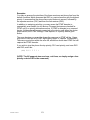
The Telephone Interface Module is registered under Part 68 of the FCC rules and regulations for
direct connection to the telephone line. A label is attached to the rear of the cabinet, listing the
registration number and ringer equivalence. It reads:
Complies With Part 68, FCC Rules
FCC Registration No. GHZ37K-10180-DP-N
Ringer Equivalence: 1.3B
The Telephone Interface Module contains lightning protection circuitry. However, it is a good
practice to install additional protection at the telephone line service entrance. The following
companies market phone line suppressors:
Citel America, Inc.
1111 Parkcentre Blvd.
Suite 474
Miami, FL 33169
(305) 621 0022 (FL)
(800) 248-3548
L-COM Data Products
1755 Osgood Street, Rte. 125
North Andover, MA 01845
(617) 682-6936
(617) 689-9484 (FAX)
ITW Linx Communications Prods
201 Scott St.
Elk Grove Village, IL 60007
(312) 952-8844
(312) 952-1633 (FAX)
MCG Electronics Inc.
12 Burt Drive
Deer Park, NY 11729
(516) 586-5125
Telex 645518
Telebyte Technology, Inc.
270 East Pulaski Road
Greenlawn, NY 11740
(516) 385-8184 (FAX)
(800) 835-3298
(516) 423-3232
PolyPhaser Corporation
1425 Industrial Way
Gardnerville, NV 89410-1237
(800) 325-7170
(702) 782-4476 (FAX)
Telex 272718
TII Industries, Inc.
1375 Akron St.
Copiague, NY 11726
(516) 789-5020 Sales
(516) 789-5000
Telex 144631
L.E.A. Dynatech
12516 Lakeland Road
Santa Fe Springs, CA 90670
(213) 944-0916
(800) 654-8087
(213) 944-0781 (FAX)
FCC rules and regulations, Part 68 require the following information be provided to the user of FCC
Registered Terminal equipment.
6K V1.02 03-16-91
23
Section 68.100 GENERAL
Terminal equipment may be directly connected to the telephone network in accordance with the
rules and regulations . . . of this part.
Section 68.104 STANDARD PLUGS AND JACKS
(a)
General
"Except for telephone company-provided ringers, all connections to the telephone network
shall be made through standard (USOC) plugs and standard telephone company-provided
jacks, in such a manner as to allow for easy and immediate disconnection of the terminal
equipment. Standard jacks shall be so arranged that if the plug connected thereto is
withdrawn, no interference to the operation of the equipment at the customer's premises
which remains connected to the telephone network shall occur by reason of such
withdrawal."
Section 68.106 NOTIFICATION TO TELEPHONE COMPANY
"Customers connecting terminal equipment or protective circuitry to the telephone network
shall, before such connection is made, give notice to the telephone company of the
particular line (s) to which such connection is to be made, and shall provide to the telephone
company the FCC Registration Number and Ringer Equivalence of the registered terminal
equipment or protective circuitry. The customer shall give notice to the telephone company
upon final disconnection of such equipment or circuitry from the particular line(s)."
Section 68.108 INCIDENCE OF HARM
"Should terminal equipment or protective circuitry cause harm to the telephone network, the
telephone company shall, where practicable, notify the customer that temporary
discontinuance of service may be required; however, where prior notice is not practicable,
the telephone company may temporarily discontinue service forthwith, if such action is
reasonable in the circumstances. In case of such temporary discontinuance, the telephone
company shall:
(1) promptly notify the customer of such temporary discontinuance, (2) afford the customer
the opportunity to correct the situation which gave rise to the temporary discontinuance, and
(3) inform the customer of the right to bring a complaint to the Commission pursuant to the
procedures set forth in Subpart E of this part."
Section 68.110 COMPATIBILITY OF THE TELEPHONE NETWORK AND TERMINAL
EQUIPMENT.
(b)
Changes in Telephone Company Facilities, Equipment, Operations or Procedures.
"The telephone company may make changes in its communications facilities, equipment,
operations or procedures, where such action is reasonably required in the operation of its
business and is not inconsistent with the rules and regulations in the Part. If such changes
can be reasonably expected to render any customer's terminal equipment incompatible with
telephone company communications facilities, or require modification or alteration of such
6K V1.02 03-16-91
24
terminal equipment, or otherwise materially affect its use or performance, the customer shall
be given adequate notice in writing, to allow the customer an opportunity to maintain
uninterrupted service."
Section 68.216 REPAIR OF REGISTERED TERMINAL EQUIPMENT AND REGISTERED
PROTECTIVE CIRCUITRY
"Repair of registered terminal equipment and registered protective circuitry shall be
accomplished only by the manufacturer or assembler thereof or by their authorized agent;
however, routine repairs may be performed by a user, in accordance with the instruction
manual if the applicant certifies that such routine repairs will not result in noncompliance
with the rules in Subpart D of this Part."
Section 68.218 (b) ADDITIONAL INSTRUCTIONS TO USER
1.
". . . registered terminal equipment or protective circuitry may not be used with party
lines or coin lines."
2.
". . . when trouble is experienced the customer shall disconnect the registered
equipment from the telephone line to determine if the registered equipment is
malfunctioning, and . . . if the registered equipment is malfunctioning, the use of
such equipment shall be discontinued until the problem has been corrected."
3.
". . . the user must give notice to the telephone company in accordance with the
requirements of Section 68.106. . ."
6K V1.02 03-16-91
25
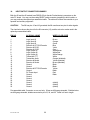
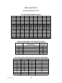
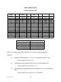
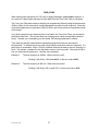
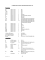
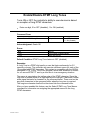
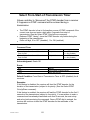
14.
INPUT/OUTPUT CONNECTOR SUMMARY
Both the 5K and the 6K models have DB25S (25-pin female D-subminiature) connectors on the
main PC board. You may use the mating DB25P (male) connector (supplied) to build a cable, or
you may purchase the optional pre-assembled cable. The cable will connect the controller to your
repeater and auxiliary equipment.
CAUTION!
The 5K has pins 16 and 18 grounded; the 6K uses these two pins for other signals.
The chart below shows the pinout for the 6K connector (J2), and the wire color codes used in the
optional pre-assembled cable.
PIN NO.
6K SIGNAL NAME
WIRE COLOR CODE
1
2
3
4
5
6
7
8
9
10
11
12
13
14
15
16
17
18
19
20
21
22
23
24
25
Logic Input #1
Logic Input #2
Logic Input #3
Receiver #1 CTCSS Decoder
Receiver #2 COR
Receiver #1 COR
Logic Output #1
Logic Output #2
Logic Output #3
Transmitter PTT
Transmitter Audio
Receiver #2 Audio
Receiver #1 Audio
Ground
Ground
Receiver #2 CTCSS Decoder
Ground
DC Power Input
Ground
Ground
Ground
Ground
Ground
Ground
Ground
Brown
Orange
Green
Blue
Violet
Gray
White/Brown
White/Red
White/Orange
White
Orange (shielded)
Yellow (shielded)
Brown (shielded)
Black
Black
Yellow
Black
Red
Black
(shield)
(shield)
(shield)
Pre-assembled cable: Connector on one end only. Wires are #24 gauge stranded. Shielded wires
are #24 gauge stranded, shields connected to pins 23, 24, and 25. Cable is 4 feet in length.
6K V1.02 03-16-91
26
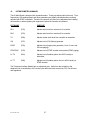
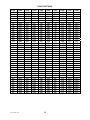
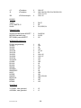
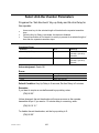
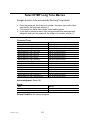
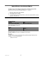
15.
POTENTIOMETER SUMMARY
The 6K Main Board is designed with 8 potentiometers. These pots adjust audio levels only. Tone
frequencies, CW sending speed, and other parameters are digitally controlled and are remotely
adjusted with DTMF commands. Therefore, the pots will only have to be adjusted when installing
the controller, or when replacing the equipment to which the controller is interfaced.
POT NAME
PURPOSE
RX1
(R75)
Adjusts audio level from receiver #1 to controller
RX2
(R76)
Adjusts audio level from receiver #2 to controller
TX
(R80)
Adjusts master audio level from controller to transmitter
CW
(R77)
Adjusts level of CW (Morse) generator
PAGE
(R78)
Adjusts level of paging tone generator (1-tone, 2-tone, and
5/6-tone paging)
DTMF ENC
(R79)
Adjusts level of DTMF encoder to transmitter (DTMF paging)
LL-TX
(R81)
Adjusts level of landline (phone line AGC'd audio) to
transmitter
LL-TT
(R82)
Adjusts level of landline (phone line non-AGC'd audio) to
DTMF decoder
The Telephone Interface Module has no adjustment pots. Audio from the controller to the
telephone line is controlled by AGC circuits to be within the levels required by FCC Part 68 rules
and regulations.
6K V1.02 03-16-91
27
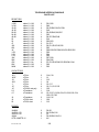
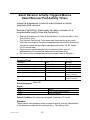
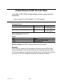
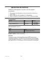
16.
SWITCH SUMMARY
The 6K Main Board has two switch assemblies, S1 and S2.
S1 is a momentary pushbutton switch used to initialize the controller. The procedure that must be
used to initialize the controller is described later in this manual.
S2 is a 6-pole dipswitch array. Five of the switches are used to invert the sense of logical input
signals. The sixth switch is used for special functions.
The five sense-reversal switches are described as follows:
DIP SWITCH #1 - Inverts Receiver #1 COR Input
DIP SWITCH #2 - Inverts Receiver #2 COR Input
DIP SWITCH #3 - Inverts Receiver #1 CTCSS Decoder Input
DIP SWITCH #4 - Inverts Receiver #2 CTCSS Decoder Input
DIP SWITCH #5 - Inverts Transmitter PTT Output
A switch in the ON (closed) position means the input is "low" active. A switch on the OFF (open)
position means the input is "high" active. Unused switches should be placed in the ON position.
6K V1.02 03-16-91
28
GETTING STARTED
1.
INTRODUCTION
In this section, we will assume that you have either completed the installation of the controller into
the repeater, or you are simulating a repeater with switches for COR signals, LEDs for PTT loads,
and so on.
If desired, the controller can be programmed on your workbench, then moved to the repeater site
for installation. Be sure to transport the controller in anti-static packing material! Large electrostatic
discharges can damage components and destroy the data stored in memory.
6K V1.02 03-16-91
29
2.
POWER ON/INITIALIZATION
Each time power is applied to the controller, it will check to see if the Initialize pushbutton is being
pressed. (The Initialize pushbutton is located in the right rear corner of the Main Board). At that
moment, the controller will decide whether to retrieve default information stored in the EPROM and
write it into the non-volatile RAM (pushbutton down), or retain the previously-stored information
(pushbutton up). If the pushbutton is pressed at any other time, it will have no effect. Since a
specific sequence is needed to initialize your controller, accidental contact with the pushbutton will
not destroy your programming efforts.
Controllers are initialized as part of the testing procedure at the factory. However, we recommend
that you do another initialization before attempting to program the controller. There may be other
occasions when you will need to initialize the controller. For example: (1) The programming
password was never written down, and was forgotten by the programmer; (2) A general erasing of
all programming is desired, since the controller is being transferred to a new repeater and will
receive all new programming; (3) You are installing a new software upgrade EPROM; or (4), It has
been necessary to replace the battery, RAM IC, RAM Controller IC, or some other part in the nonvolatile RAM circuit. In this last case, you must perform the initialization sequence twice to ensure
proper operation of the RAM Controller IC.
To initialize the controller, follow these four steps:
Step 1: Remove power from the controller. This can be done by pulling out the 2.5 mm DC
power plug.
Step 2: Press and hold down the Initialize pushbutton.
Step 3: While holding down the pushbutton, restore power to the controller. This can be
done by inserting the 2.5 mm DC power plug.
Step 4: Continue holding down the pushbutton for several seconds after the power has
been restore.
An initialization is sometimes called a cold start. Applying power without doing an initialization is
sometimes called a warm start. When a cold start occurs, the controller will send "? RES C"
(reset, cold) in CW. When a warm start occurs, the controller will send "? RES" (reset) in CW.
After an initialization, we say that the controller's programming is in the Default Condition. Default
conditions are necessary if we want the controller to be able to operate the repeater before we've
had a chance to program it. An initialization can therefore be thought of as a quick "preprogramming" of the controller.
Most commands have default conditions. They are in effect until you change them through
programming. The default conditions are described with the commands later in this manual.
NOTE: There is a push-on jumper in the Main Board that is used to disconnect the battery from the
RAM IC. This jumper is removed during some repair operations, and during current drain tests.
Removing this jumper will not initialize the controller! Removing and replacing the jumper will
require an initialization sequence before proper operation will resume.
6K V1.02 03-16-91
30
3.
TESTING THE CONTROLLER-TO-REPEATER TRANSMITTER INTERFACE
Apply power to both the controller and the repeater while monitoring the repeater with an extra
receiver. When power is applied, the transmitter should key and send the reset CW message. If
the transmitter does not key at all, check the wiring. Both the controller and the repeater should be
powered up. Check the connection between the controller's PTT output and the transmitter's PTT
input. If the transmitter keying is acting "upside down" (unkeying during the message but keying
afterwards), reverse the repeater transmitter PTT dipswitch.
If the transmitter is keying properly but no CW message is heard, check the wiring from the
controller's Repeater Transmitter Audio Output to the transmitter's audio input. If the CW message
is too loud or too soft, adjust the CW pot on the Main Board (see Messages section in this manual).
Turn the pot clockwise to increase the level, and counter-clockwise to decrease the level.
If the CW message is still too loud with the pot turned nearly all the way down, you may be
attempting to drive the microphone input of the transmitter instead of a later stage. If you cannot
drive a later stage, then check the Transmitter Audio Output description in the installation section of
this manual for information on decreasing the transmitter drive level.
6K V1.02 03-16-91
31
4.
TESTING THE CONTROLLER-TO-REPEATER RECEIVER INTERFACE
Generate an RF signal on the repeater's input frequency. The controller should key the repeater
transmitter. When the signal disappears, a short courtesy beep should be heard. The transmitter
should stay keyed for a few more seconds, then it should unkey. If this does not happen, check the
wiring between the repeater receiver's COR driver and the controller's Receiver #1 COR Input.
Check the voltage on the COR line to see if it swings above and below the required threshold.
(Check the voltage with the controller and receiver connected, not just the open-circuit COR output
from the receiver).
If the repeater is acting "upside down" (unkeying when a signal exists but keying afterwards),
reverse the Receiver #1 COR dipswitch.
The default condition of the controller causes a 0.5-second delay between the loss of carrier and
the courtesy beep. The transmitter will stay keyed for an additional 3.0-second dropout delay.
These characteristics may all be changed later, so do not be concerned if this is not the way you
wish the repeater to act.
Generate a modulated RF signal on the repeater's input frequency (a service monitor is quite
helpful). Check the audio level as instructed in the Repeater Receiver Audio part of the Installation
section. Check the transmitter for proper deviation, and adjust the Transmitter Audio Output pot as
necessary.
6K V1.02 03-16-91
32
5.
TESTING THE DTMF DECODER
a.
Introduction
Your controller uses an 8880-type DTMF Transceiver IC. This crystal-controlled device encodes
and decodes all 16 DTMF digits. It has an extremely wide dynamic range (30 dB), and can detect
digits that have as much as -6 dB to +6 dB of twist. ("Twist" refers to the difference in amplitude
between the two individual tones that are summed to make up a DTMF digit. The more twist a
system gives to DTMF digits, the more difficult it is to detect the digits). Twist, in repeater systems,
can be caused by the user's transmitter.
The audio fed into the transmitter is pre-emphasized before it is applied to the limiter circuit. Preemphasis causes high frequency tones to have more amplitude than low frequency tones, so the
high frequency tone of a DTMF digit can be severely clipped while the low frequency tone is not.
The result is twist, and the solution is the keep the DTMF pad audio at a reasonably low level. The
repeater receiver can also introduce twist if it has poor audio response, or if a poor impedance
match exists between the receiver and the controller.
b.
Command Sources
The DTMF decoder can monitor all receiver inputs and the phone line for incoming digits, but it can
monitor only one device at a time. Therefore, a priority scheme is used to determine which source
feeds the decoder at any given time. If no source is active, the decoder's input is grounded.
c.
Local Control
You can program the controller with a local DTMF keyboard, if desired. Connect the audio from the
keyboard to the Receiver #1 Audio Input, and connect a switch between the RX #1 COR input and
ground. Whenever the switch is ON (closed), the controller will accept commands from the
keyboard. Or, you can use the same scheme with Receiver #2 and leave the keyboard
permanently connected. Return the switch to the OFF (open) position when finished programming,
so that the repeater receiver (#1) can drive the DTMF decoder one again.
d.
Testing
Generate an RF signal on the repeater's input frequency. While listening to the repeater output on
an extra receiver, send some DTMF digits to the repeater. You should hear a short burst of DTMF,
followed by silence, as the controller detects the digit and then mutes it.
If the digits are passed through to the transmitter with no muting taking place, then the DTMF
decoder is not recognizing the digits. There are several areas to check:
1.
Check the audio level at the output of the Receiver #1 audio op amp; it should be 700 mV
rms (2 V p-p) as discussed in the installation section.
2.
Check the operation of the Receiver #1 COR input. If the COR input isn't active, the DTMF
decoder will not be monitoring the repeater receiver audio.
3.
Check the other receiver COR input and associated dipswitch. If a higher-priority input is
active, the DTMF decoder will be monitoring that input, not the repeater receiver.
6K V1.02 03-16-91
33
4.
Check to see if a command was entered to disable the DTMF decoder from the repeater
receiver.
e.
Falsing
Some user's voices can contain frequency components that appear as DTMF digits to the decoder.
If such a digit is detected, "falsing" is said to occur. If the DTMF Muting feature is enabled, then the
result of falsing is the loss of repeat audio for a syllable or two.
Also, an accidental digit is stored into the controller's command buffer. However, this last item is
not usually a problem, as the digit will be discarded after a few seconds when the controller
discovers that the digit was not part of a valid command.
In any case, falsing is annoying and can usually be cured to an acceptable extent. Several
solutions are available:
1.
TURN OFF THE DTMF MUTING FEATURE. If you do this, then all DTMF digits will be
repeated. This is a simple fix, but it may not be acceptable for repeaters that need security
on DTMF commands.
2.
DON'T OVERDRIVE THE DTMF DECODER. The higher the audio level to the decoder,
the more likely it is to false. Check the audio level at the output of the receiver's op amp; if
over the recommended 700 mV rms (2 V p-p), turn it down. Overdriving the decoder does
not help it decode any better.
3.
INCREASE THE DTMF DECODER'S DETECT TIME. The decoder's tone detect time is
controlled by resistor R7, which is 300K as shipped from the factory. This provides a rather
fast 40 mS detect time (a telephone company standard). Increasing R7 will require a longer
detect time, thus reducing the possibility of falsing.
The disadvantage of slowing the detection time is that some DTMF autodialers generate
digits at a rapid rate; a long detection time could result in missed digits.
If autodialers are not a problem, then increasing the detection time will make a noticeable
improvement in falsing. Field experience has shown that changing R7 to 500K will solve
minor cases, and changing it to 1M solves nearly all cases. The slower response to DTMF
digits has not been a problem for users, since the increase in time is small by human
operator standards.
6K V1.02 03-16-91
34
PROGRAMMING FUNDAMENTALS
1.
INTRODUCTION
You program the controller by entering strings of DTMF digits. These strings of digits are referred
to as commands. A standard DTMF keyboard with 12 digits may be used for nearly all commands.
A few advanced features are available to programmers with 16-button keyboards. The extra four
lettered keys may be used in passwords or macro names to increase the security of the system.
As shipped from the factory, the DTMF decoder requires about 40 mS to detect a valid digit. The
microprocessor scans the decoder once every 10 mS to see if a digit has been detected. Thus, it
can take about 50 mS to store a valid digit. Allowing a 50 mS pause between digits, the controller
is able to store about 10 digits per second. Since these are best-case times, use longer durations
and pauses if you wish to reliably program the controller with automatic DTMF sending equipment.
The controller may be programmed over any of the receiver inputs and the telephone line, if
enabled. The controller responds to valid commands by sending acknowledgement messages.
These responses may be disabled if desired.
In this section of the manual, we will discuss the basic structure of control commands.
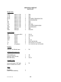
2.
CONTROL COMMAND STRUCTURE
All control commands follow the format described as follows:
1.
A control command always begins with a password. The password increases the security
of the system. It can be changed at any time. The password can be 2, 4 or 6 digits long,
and may consist of any combination of the numbers 0 through 9, and the letters A, B, C and
D. Star (*) and pound (#) are not allowed in passwords. The controller supports several
passwords, used in programming the system and in accessing the autopatch.
2.
Following the password is a root number. The root number tells the controller which
function the owner wishes to program. Root numbers are either 2 or 4 digits long, and
consist only of the numbers 0 through 9. Each control command has a unique root number.
The root number is fixed by the controller's internal software and cannot be changed.
3.
Following the root number may be one or more data digits. Some commands are quite
simple, and do not need any data digits. Other commands will require a string of data digits.
4.
Following the data digits (if any) is a terminator. The terminator can be either the star
character (*) or a carrier drop (if enabled). The star character will always work as a
terminator; in fact, it is necessary when programming the controller via the telephone, since
there is no carrier to drop.
The terminator tells the controller that the command has ended. It is necessary, since
control commands vary in length. The terminator is similar to a "carriage return" on a
computer keyboard, or the "equals" key on a calculator.
6K V1.02 03-16-91
35
Here's an example of a control command:
99 70 123 *
We've put spaces between some digits to help explain this example. You do not need any pauses
between digits when you are programming the controller.
The password in this example is 99, the default password. The password tells the controller that
you are a legitimate programmer.
The root number is 70. This root number tells the controller that you wish to turn on some logic
outputs.
The data digits are 1, 2, 3. In this particular command, the digits 1, 2, 3 tell the controller that you
want to turn on logic outputs 1, 2, and 3.
The terminator is *, which tells the controller that you have reached the end of this particular
command. The controller always waits for the terminator before it processes a command.
If we have made no mistakes in entering this command, the controller will respond with a message
and turn on the outputs. If a mistake were made in the command, such as asking for output 0 to
turn on, then the controller would have sent an error message. None of the outputs would have
changed. If you enter a control command with an incorrect password or a non-existent root
number, the controller will not respond to the command.
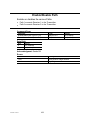
3.
RESPONSE MESSAGES
Most control commands respond in some way to tell you that they were accepted, or that you made
a mistake in entering the command. The usual acknowledgement message is "OK" (sent in CW).
If another response is more appropriate, then it will be sent instead of the "OK". There are two
commonly-used error messages, sent as "? ERR 1" and "? ERR 2". They are defined as follows:
"? ERR 1"
means you have made an error in the number of keystrokes you entered for
this particular command. If the command requires 5 keystrokes, for
example, and you entered 6, then the response will be an error 1.
"? ERR 2"
means you have made an error in the data that was presented for this
particular command. If a timer, for example, has a range of 0 to 5.0
seconds, and you enter 6.0 seconds, then the response will be an error 2.
Response messages can be turned on and off.
4.
SPECIAL KEYS
There are two keys on your 12-button or 16-button DTMF keyboard that have special meanings to
the controller. They are the star (*) and pound (#) symbols. (The "#" symbol is technically called an
octothorpe . . . but we'll just call it a "pound"). These two characters are not allowed to be part of a
password or macro name, and they won't be found in root numbers or data digits.
6K V1.02 03-16-91
36
As mentioned earlier, the star (*) digit serves as a terminator, indicating to the controller that you
have finished entering a command. The "*" will always work as a terminator. You can also allow a
carrier drop to work as a terminator if you wish; the carrier drop method can be turned on and off,
but the "*" method can't be turned off, and will terminate any command.
Why do we have the two methods? It's easier to terminate a command by simply releasing the PTT
(push-to-talk) button on your microphone, and you have saved one keystroke (the "*"). However,
there could be a weak carrier on the repeater's input frequency some day when you enter a
command. If the carrier continues to hold up the repeater after you've released the PTT button,
your command won't be executed. Entering the "*" at the end of the command will guarantee that
the command is properly terminated.
A second reason for using the "*" terminator is that you may enter a series of commands, one after
the other, without releasing the PTT button. (You do not have to wait for the acknowledgement
message before entering the next command). You must, of course, use the "*" terminator when
entering commands from a Touch-Tone (R) telephone, since there is no carrier drop for the
controller to detect.
The pound (#) digit serves as a "clear" or "abort" key. It indicates to the controller that you have
made an error, and you wish to clear the command buffer. (The command buffer is a holding area
for the partially-entered command). The "#" key only works if the command is still in the buffer, and
has not been executed. When you enter the terminator, the command is immediately executed and
it is too late to clear the buffer. You may start entering the next command immediately after
pressing the "#" key. There is no acknowledgement message sent by the controller when a
command is cleared. Any digits following the "#" digit will be considered a new command.
5.
DTMF INTERDIGIT TIMER
The controller uses a DTMF Interdigit Timer for the purpose of clearing the command buffer if a
command is not completely entered. For example, if a user accidentally presses a digit, or if a digit
is "falsed" into the buffer, or if a user drives out of range or his signal flutters while entering a
command, then the command buffer will have only a piece of a command. If the controller had no
time limit between digits, then that piece of a command would stay in the buffer. The controller
would confuse it with the next command it receives.
The Interdigit Timer works as follows: When you release any DTMF key, the timer is started. If you
do not enter another DTMF digit within the time limit, the controller will clear the command buffer.
The Interdigit Timer initially defaults to 5.0 seconds, but it can be reprogrammed with a different
value if desired.
6.
DTMF MUTE DELAY
The controller has a DTMF Mute feature that prevents your DTMF commands from being repeated.
This feature can be turned on and off.
Unless your controller has been fitted with the optional Audio Delay Module, there will be a short
burst (40 to 50 mS) of DTMF that is repeated at the beginning of a digit. This short burst occurs
because the controller requires some time to detect the DTMF digit and shut off the audio gate.
To reduce the number of bursts, the controller will continue to mute the audio for a while after you
6K V1.02 03-16-91
37
have released the DTMF key. Thus, if you enter a string of digits rapidly, there will be only a single
burst (caused by the beginning of the first digit). If you wait too long between digits, the muting will
end. The next digit you enter will cause a short burst at the beginning. The Mute Delay Timer
initially defaults to 0.5 seconds, but it can be reprogrammed with a different value if desired.
6K V1.02 03-16-91
38
MESSAGES
1.
INTRODUCTION
Your controller uses messages to communicate with both the users of your repeater and the
programmers of the repeater controller. Messages may be composed of combinations of CW
(Morse) characters, beeps, DTMF characters, and various paging formats. Most of the controller's
messages are remotely programmable via DTMF commands.
2.
MESSAGE ADJUSTMENT POTS
Three of the 6K's eight pots are associated with messages. The three pots are:
CW
(R77)
Adjusts the level of the CW generator. Adjusting R77 will affect the
CW level going to the transmitter and the CW level going to the
telephone line.
PAGE
(R78)
Adjusts the level of the page tone generator. Adjusting R78 will
affect the level used for 1-tone, 2-tone, and 5/6-tone pages to the
transmitter.
DTMF ENC
(R79)
Adjusts the level of the DTMF generator when sending DTMF pages
to the transmitter. Does not adjust the level of DTMF digits when
dialing the phone.
All pots adjust clockwise to increase level, and adjust counter-clockwise to decrease level.
CW level is typically set to a low level of deviation (500 Hz to 1.5 KHz). CW identifications must be
recognizable, but they should not interfere with voice conversations.
Page levels are typically set to a high level of deviation (3.0 KHz to 3.3 KHz) so they can reliably trip
pagers.
DTMF level should be set per the requirements of your DTMF receiving equipment. High levels
should be avoided to minimize twist problems. Note that the level of DTMF characters sent to the
phone line when dialing is not adjustable. This level is fixed in accordance with FCC Part 68 rules
and regulations.
When sending tone pages, the controller can acknowledge by sending the page to the phone line.
This level is the same as the CW level.
6K V1.02 03-16-91
39
3.
MESSAGE THEORY OF OPERATION
The controller uses a large area of memory, called the Message Buffer, to temporarily store the
messages that it is asked to send. The Message Buffer is a "FIFO" buffer (First-In, First-Out), which
means that the first message to arrive is the first one sent out. The purpose of the buffer is to
prevent overruns when several software programs need to send messages simultaneously.
The various messages are loaded into the buffer by the programs that need to send their
messages; the messages are unloaded by a program called the Message Handler. The Message
Handler needs to know the type of message it is unloading, so that it can operate the proper
hardware (DTMF encoder, tone encoder, etc.). The way we tell the Message Handler the type of
message we desire is with special Control Characters.
6K V1.02 03-16-91
40
4.
MESSAGE CONTROL CHARACTERS
All Control Characters are four (4) digits long, and always begin with 99. The 99 tells the Message
Handler that special instructions follow. The next two digits contain those special instructions. The
Control Characters that have been defined to date are:
CONTROL CHARACTER DEFINITIONS
9900
9910
9920
9930
9940
9950
CW Characters follow
Beep Characters follow
A Single-Tone Page follows
A Two-Tone Page follows
A 5/6-Tone Page follows
DTMF Characters follow
9981
9983
9985
9987
Route the following message to the transmitter
Route the following message to the phone line
Unroute the following message to the transmitter
Unroute the following message to the phone line
Any programmable message can contain any mixture of message types and routings described
above. Therefore, a message could be made up of several different types of characters or tone
pages, intended for different destinations.
When programming a message, first enter the routing, then the type of message, then the message
itself.
Routing codes were developed to give the customer control over the routing of messages to the
transmitter and phone line. You can use these codes to force IDs, courtesy beeps, timeout
messages, and so on to go to the transmitter, even when a control operator is programming via the
phone line.
When the message ends, the Message Handler defaults back to standard routing. Standard routing
means that all messages normally go to the transmitter except when a control operator is
programming the controller via the phone line, in which case all messages are sent to the phone
line.
The following sections discuss each message type in greater detail.
6K V1.02 03-16-91
41
5.
CW MESSAGES
A. Control Character
The Control Character 9900 should be entered before the actual CW characters when
building a CW message. If a message does not begin with a Control Character, the
Message Handler will assume that the message should be sent in CW. Therefore, a CWonly message would not require the 9900. However, a message could be made up of
mixed types, such as a series of beeps followed by CW characters. In that case, the
Control Character 9900 is needed before the CW portion of the message.
B. Format
Enter the Control Character 9900. Then enter the various CW character codes described in
the "CW Character Set" to create the desired message. You may end the CW message
with the * character, or you may enter another Control Character (99xx) and continue with
another message type.
C. Delay Character
A special pre-message delay character, 54, can be programmed after the Control Character
9900 but before the CW characters. The 54 causes the Message handler to pause for 1
second before sending the CW message. Any additional 54s found after the first one will be
ignored. If the CW message was preceded by another message, the 54 will be ignored.
D. Wordspace
The wordspace character, 40, should be placed between the words in a CW message.
The Message Handler will automatically place a wordspace at the end of a CW message,
so you won't have to remember to do so. This feature prevents two adjacent CW messages
from being run together.
Wordspace characters can be used as pauses during a CW message. However, the length
of the pause will depend upon the current sending speed of the CW (words-per-minute).
E. Frequency Change
The CW frequency (pitch) may be changed before, or during a CW message. This feature
allows you to draw attention to a certain message (or part of a message). A 6-digit
character, 59xxxx, should be entered ahead of the CW characters that which are to be sent
at the new frequency. The four digits following the 59, shown as xxxx, represent the new
frequency and are taken from the Tone Code Table.
The frequency may be changed as often as desired within a CW message (even between
each character).
6K V1.02 03-16-91
42
At the end of a CW message, the Message Handler will change the frequency back to
normal. This allows you to create a special CW message with a unique pitch, and not worry
about changing the frequency back to normal to prevent affecting later messages.
If you wish to change the CW frequency for ALL CW messages, see the CW Frequency
Control Command.
F. Speed Change
The CW sending speed in WPM (words per minute) may be changed before, or during a
CW message. The speed may be varied from 5 to 40 WPM in ten steps. This feature
allows you to draw attention to a certain CW message, or make it more easily copies by
those with modest CW skills.
To temporarily change the sending speed of a CW message, enter a 2-digit character from
60 to 69 ahead of the CW characters that are to be sent at the new speed.
The speed may be changed as often as desired within a CW message (even between each
character).
At the end of a CW message, the Message Handler will change the sending speed back to
normal. This allows you to create a special CW message with a unique speed, and not
worry about changing the speed back to normal to prevent affecting later messages.
If you wish to change the sending speed for ALL CW messages, see the CW Speed Select
Control Command. If you wish to allow users to slow down CW messages, see the Send
Next Message Slowly command.
G. Alphanumeric Characters
The controller features a library of 54 alphanumeric CW characters, consisting of the
numerals 0 through 9, the letters A through Z, punctuation and standard Morse
abbreviations. Each character is represented by a 2-digit code from 00 to 53. When
building a CW message, be sure to use both digits of the code (do not omit leading zeroes).
6K V1.02 03-16-91
43
CW CHARACTER SET
CW Control Character = 9900
Char.
0
1
2
3
4
5
6
7
8
Code
00
01
02
03
04
05
06
07
08
Char.
9
A
B
C
D
E
F
G
H
Period
Comma
Fraction
Question
Space
End-of-Msg
Wait
Break
Double Dash
.
,
/
?
AR
AS
BK
BT
Code
09
10
11
12
13
14
15
16
17
36
37
38
39
40
41
42
43
44
Char.
I
J
K
L
M
N
O
P
Q
End-of-Work
Hyphen
Colon
Semicolon
Parenthesis
Apostrophe
Exclamation
Quotation
Understood
1.0-Second Pre-Message Delay
Frequency Change
WPM
5
7
10
13
15
6K V1.02 03-16-91
Code
18
19
20
21
22
23
24
25
26
SPEED CHANGE
Code
WPM
60
17
61
20
62
24
63
30
64
40
44
Char.
R
S
T
U
V
W
X
Y
Z
SK
:
;
()
'
!
"
54
59xxxx
Code
65
66
67
68
69
Code
27
28
29
30
31
32
33
34
35
45
46
47
48
49
50
51
52
53
6.
BEEP MESSAGES
A. Control Character
The Control Character 9910 must be entered before the actual beep characters when
building a beep message. Remember, any message that does not have a control character
will be interpreted as a CW message!
B. Format
Enter the Control Character 9910. Then enter the various beep character codes described
in the Beep Character Set to create the desired message. You may end the beep message
with the * character, or you may enter another Control Character (99xx) and continue with
another message type.
C. Delay Character
A special pre-message delay character, 54, can be programmed after the Control Character
9910 but before the beep characters. The 54 causes the Message handler to pause for 1
second before sending the CW message. Any additional 54s found after the first one will be
ignored. If the beep message was preceded by any other message, the 54 will be ignored.
D. Factory-Fixed-Frequency Beeps
Forty-eight (48) beeps have been defined in frequency but have variable duration. These
beeps are programmed with the character codes 00 through 47 and cover almost four
octaves from 262Hz to 3951Hz. It is best to avoid beeps below 300Hz and above 3000Hz,
since most radio systems are designed for 300-3000Hz response.
E. Owner-Fixed-Frequency Beeps
Six (6) beeps are definable in frequency by the owner, and have variable duration. They
default to factory-selected frequencies upon a cold start. The frequencies may be changed,
and the new frequencies will be retained upon a warm start. These beeps are programmed
with the character codes 48 through 53.
F. Custom Beeps
Custom Beeps are defined "on-the-fly" in both frequency and duration. An 8-digit character,
57xxxxyy, defines the Custom Beep. The four digits following the 57, shown as xxxx,
represent the frequency and are taken from the Tone Code Table. The next two digits,
shown as yy, represent the duration in tens of milliseconds.
Custom beeps allow you to create a unique message with any frequency and any duration
to 990mS. As an example, let's define a custom beep of 1275Hz for 70mS. The custom
beep code would be 57078407.
6K V1.02 03-16-91
45
G. Custom Delay
Custom Delays are defined "on-the-fly" in duration. A 4-digit character, 58xx, defines the
custom delay. The two digits following the 58, shown as xx, represent the duration of the
delay in tens of milliseconds.
Although custom delays can be placed anywhere in a beep message, they go well with
custom beeps if you need to create a truly unique or specialized signaling burst. For
example, a string of custom beeps and custom delays could be used to generate a string of
ASCII characters of the proper tones for use with modems.
H. Gap Characters
Gap Characters are used to introduce a silent period between beeps. Ten (10) gap
characters have been defined from 10mS to 320mS using the codes 60 through 69. Gap
characters may be used alone to separate groups of beeps, or they can be automatically
placed after every beep by using the Automatic Gap On code (described later). Note that
any time a gap character is entered, the Message Handler remembers its duration. When
the Automatic Gap On character is encountered, the Message Handler will use the
duration that it remembered from the previous gap character. This is also true of the
Custom Delay character. This parameter is not changed at the end of the beep message.
I. Beep Duration Change
Beep Duration Change characters are used to set the duration of the beep characters that
follow. Ten (10) duration change characters have been defined from 10mS to 320mS using
the codes 70 through 79. The beep duration may be changed as often as desired within a
beep message (even between each beep).
Note that any time a beep duration change is made (including a Custom Beep), the duration
will be remembered by the Message Handler. When any succeeding beep is encountered,
the Message Handler will use the duration that it remembered from the previous duration
change.
This parameter is not changed at the end of the beep message.
J. Automatic Gap On
The Automatic Gap On character, 56, causes the Message Handler to place a gap between
each beep. The duration of the gap depends on that last gap that was encountered. It
defaults to 10mS upon a cold start.
K. Automatic Gap Off
The Automatic Gap Off character, 55, causes the Message Handler to send the beeps that
follow in a series without any gaps between them.
6K V1.02 03-16-91
46
L. Defaults
Upon a cold start, the following defaults will be forced:
Beep Duration
Gap Duration
Automatic Gap
6K V1.02 03-16-91
60mS
10mS
OFF
47
BEEP CHARACTER SET
Beep Control Character = 9910
FACTORY FIXED-FREQUENCY BEEPS
Code
Hz
Note
Code
Hz
Note
Code
Hz
Note
00
01
02
03
04
05
06
07
08
09
10
11
12
13
14
15
262
277
294
311
330
349
370
392
415
440
466
494
523
554
587
622
C3
C#3
D3
D#3
E3
F3
F#3
G3
G#3
A3
A#3
B3
C4
C#4
D4
D#4
16
17
18
19
20
21
22
23
24
25
26
27
28
29
30
31
659
698
740
784
831
880
932
988
1046
1109
1175
1244
1319
1397
1480
1568
E4
F4
F#4
G4
G#4
A4
A#4
B4
C5
C#5
D5
D#5
E5
F5
F#5
G5
32
33
34
35
36
37
38
39
40
41
42
43
44
45
46
47
1661
1760
1865
1976
2093
2217
2349
2489
2637
2794
2960
3136
3322
3520
3729
3951
G#5
A5
A#5
B5
C6
C#6
D6
D#6
E6
F6
F#6
G6
G#6
A6
A#6
B6
OWNER-PROGRAMMED, FIXED-FREQUENCY BEEPS
Code
Owner-Programmed Freq (Hz)
Default
(owner fills in)
Freq (Hz)
48
500
49
750
50
1000
51
1250
52
1500
53
1750
GAP CHARACTERS & BEEP DURATION CHANGE CHARACTERS
Code
Gap (mS)
Code
Duration change (mS)
60
10
70
10
61
20
71
20
62
30
72
30
63
40
73
40
64
60
74
60
65
80
75
80
66
120
76
120
67
160
77
160
68
240
78
240
69
320
79
320
6K V1.02 03-16-91
48
1 Sec. Pre-Msg Delay
Automatic Gap Off
Automatic Gap On
6K V1.02 03-16-91
MISCELLANEOUS
54
Custom Beep
55
Custom Delay
56
49
57xxxxyy
58xx
7.
SINGLE-TONE PAGE
A. Control Character
The Control Character 9920 must be entered before the actual page code when building a
single-tone page message. If several single-tone pages are to be sent, then the control
character 9920 must exist before each page code.
B. Format
Enter the Control Character, 9920. Then enter four digits representing the frequency of the
page tone, taken from the Tone Code Table. Then enter two digits representing the
duration of the page tone in tenths of seconds. The range of duration is 0.1 to 9.9 seconds.
You may end the message with the * character, or you may enter another Control Character
(99xx) and continue with another message type.
For example, the format of a single-tone page of 1050Hz for 8.0 seconds (National Weather
Service standard page) is 9920 0952 80.
C. Delays
A 1-second pre-page delay is created by the Message Handler for the first page in a group.
If additional pages follow, the pre-page delay is eliminated in succeeding pages.
A 3-second post-page delay is created by the Message Handler for all single-tone pages.
6K V1.02 03-16-91
50
8.
TWO-TONE SEQUENTIAL PAGE
A. Control Character
The Control Character 9930 must be entered before the actual page code when building a
two-tone sequential page message. If several two-tone pages are to be sent, the control
character 9930 must exist before each two-tone page code.
B. Format
Enter the Control Character, 9930. Then enter four digits representing the frequency of the
first tone, taken from the Tone code Table. Then enter two digits representing the duration
of the first tone in tenths of seconds. The range of duration is 0.1 to 9.9 seconds. Then
enter four digits representing the frequency of the second tone, taken from the Tone Code
Table. Then enter two digits representing the duration of the second tone in tenths of
seconds. The range of duration is 0.1 to 9.9 seconds. You may end the message with the *
character, or you may enter another Control Character (99xx) and continue with another
message type.
For example, the format of a two-tone sequential page of 349.0Hz for 1.0 seconds followed
by 433.7Hz for 3.0 seconds is 9930 2865 10 2306 30.
C. Delays
A 1-second pre-page delay is created by the Message Handler for the first page in a group.
If additional pages follow, the pre-page delay is eliminated in succeeding pages.
A 1.3-second post-page delay is created by the Message Handler for all two-tone sequential
pages.
6K V1.02 03-16-91
51
9.
FIVE/SIX-TONE PAGE
A. Control Character
The Control Character 9940 must be entered before the actual page code when building a
5/6-tone page message. If several 5/6-tone pages are to be sent, the control character
9940 must exist before each 5/6-tone page code.
B. Format
Enter the Control Character, 9940. Then enter the Preamble Digit (0 - 9), followed by the
five digits (0 - 9), followed by a 1 if you wish to send the X ("dual-address") tone or a 0 if you
do not wish to send the X tone. You may end the message with the * character. If you wish
to enter another Control Character (99xx) and continue with another message type, then
you must add another digit to the end of the 5/6-tone page. This is required because the
normal format results in an odd number of characters (11), and the Message Handler
expects messages to have even numbers of characters.
For example, the format of the 5/6-tone page "1-13657X" is 9940 1136571. If no "X" tone is
desired, the format is 9940 1136570. To send a second page in the same message, a
"bogus" digit would be added at the end of the first page to restore evenness to the
command. The format would be 9940 1136571 0 9940 1136571. Note that we added a
bogus zero digit to force the second page to begin on an even digit count.
The Message Handler always required a preamble digit. It will automatically substitute the
"R" tone for a repeated digit.
C. Delays
A 1-second pre-page delay is created by the Message Handler for the first page in a group.
If additional pages follow, the pre-page delay is eliminated in succeeding pages.
A 1-second post-page delay is created by the Message Handler for all 5/6-tone pages.
6K V1.02 03-16-91
52
10.
DTMF PAGE
A. Control Character
The Control Character 9950 should be entered before the actual DTMF character codes
when building a DTMF Page message. If a message does not begin with a Control
Character, the Message Handler will assume that the message should be sent in CW!
B. Format
Enter the Control Character 9950. Then enter the various DTMF character codes described
in the "DTMF Character Set" to create the desired message/page. You may end the DTMF
message with the * character, or you may enter another Control Character (99xx) and
continue with another message type.
C. Delays
A 1-second pre-page delay is created by the Message Handler for the first page in a group.
If additional pages follow, the pre-page delay is eliminated in succeeding pages.
A 1-second post-page delay is created by the Message Handler for all DTMF pages.
If desired, a DTMF page can consist of several DTMF digits, a pause, more DTMF digits,
another pause, and so on. This feature allows you to place a series of DTMF pages within
one message.
D. DTMF Characters
There are 16 DTMF characters: Numerals 0 through 9, letters A through D, and the symbols
"*" and "#". Each character has a two-digit code, shown on the DTMF Character Set chart.
Enter the appropriate two-digit code for each DTMF character that you wish to send.
E. Duration Change
You may wish to change the duration of the DTMF characters from the default duration of
100 mS. Ten of the most common durations are shown on the DTMF Character Set chart. If
you wish to change the duration to one of the values shown, enter the two-digit code
corresponding to your choice. If the duration you want is not on the chart, then go to the
"Custom Duration Change" description below. Once you change the duration, it will stay at
the new value indefinitely, or until changed again by another code.
F. Custom Duration Change
The easiest way to change the duration of the DTMF characters is to use the 2-digit codes
mentioned in part (E) above. However, you may require other durations, so the controller
allows you to choose a custom duration. Duration may be set from 10 mS to 9900 mS (0.01
to 9.9 seconds). Use the code "50xx" where "xx" is a number from 01 to 99 to get durations
from 10 mS to 990 mS. Use the code "51xx" where xx is a number from 01 to 99 to get
durations from 100 mS to 9900 mS. Once you change the duration, it will stay at the new
6K V1.02 03-16-91
53
value indefinitely, or until changed again by another code.
G. Gap Change
Every DTMF character sent by the controller is followed by a "gap", or silent period. You
may wish to change the duration of this gap from the default value of 100 mS. Ten of the
most common gap durations are shown on the DTMF Character Set chart. If you wish to
change the gap to one of the values shown, enter the two-digit code corresponding to your
choice. If the gap you want is not on the chart, then go to the "Custom Gap Change"
description below. Once you change the gap duration, it will stay at the new value
indefinitely, or until changed again by another code.
H. Custom Gap Change
The easiest way to change the duration of the gap is to use the 2-digit codes mentioned in
part (G) above. However, you may require other gap durations, so the controller allows you
to choose a custom gap duration. Duration may be set from 10 mS to 9900 mS (0.01 to 9.9
seconds). Use the code "52xx," where "xx" is a number from 01 to 99, to get gaps from 10
mS to 990 mS. Use the code "53xx" where "xx" is a number from 01 to 99, to get gaps from
100 mS to 9900 mS. Once you change the gap duration, it will stay at the new value
indefinitely, or until changed again by another code.
NOTE: If you intend to program a large number of DTMF pages with varying tone durations
and gap durations, it would be a good idea to set up the proper duration values at the
beginning of each individual page. Otherwise, the old values from the previous page will be
used for the new page.
I. Pause
Unlike a "gap", which is automatically sent after each DTMF character, a "pause" may be
inserted anywhere in a DTMF page. Pauses are typically used to separate individual pages
within a multi-page message.
Ten common pause durations are shown on the DTMF Character Set chart. If you wish to
insert a pause into a page, enter the two-digit code corresponding to your choice. If the
pause you want is not on the chart, then go to the "Custom Pause" description below.
J. Custom Pause
The easiest way to insert a pause is to use the 2-digit codes mentioned in part (I) above.
However, you may require other pauses, so the controller allows you to choose a custom
pause. Duration may be set from 10 mS to 9900 mS (0.01 to 9.9 seconds). Use the code
"54xx", where "xx" is a number from 01 to 99, to get pauses from 10 mS to 990 mS. Use
the code "55xx", where "xx" is a number from 01 to 99, to get pauses from 100 mS to 9900
mS.
NOTE: Since each DTMF character is followed by a gap, be sure to add the gap duration to
the pause duration if you want an accurate idea of the time between two DTMF pages.
6K V1.02 03-16-91
54
NOTE: Pauses are "additive": A long pause may be created by placing a series of pauses
together within a DTMF page.
K. Defaults
Until changed by the codes mentioned, the DTMF tone duration is 100 mS, and the gap
between DTMF characters is 100 mS.
L. Other Notes
The DTMF decoder is turned off during DTMF pages to prevent the page from being acted
on by the controller.
Since the DTMF encoder is shared between the DTMF paging function and the DTMF
autopatch dialing function, there may be a delay in paying while a number is dialed (or vice
versa).
6K V1.02 03-16-91
55
DTMF CHARACTER SET
Control Character = 9950
DTMF
Character
0
1
2
3
4
5
6
7
8
9
A
B
C
D
*
#
Code
00
01
02
03
04
05
06
07
08
09
10
11
12
13
14
15
Duration
Change (mS)
30
40
50
60
70
80
90
100
150
200
Code
20
21
22
23
24
25
26
27
28
29
Custom Duration Change
Custom Gap Change
Custom Pause
Gap
Change (mS)
20
30
40
50
60
70
80
90
100
150
Code
30
31
32
33
34
35
36
37
38
39
Pause (mS)
100
200
300
400
500
600
700
800
900
1000
Code
40
41
42
43
44
45
46
47
48
49
50xx, xx = 01-99 x 10 mS
51xx, xx = 01-99 x 100 mS
52xx, xx = 01-99 x 10 mS
53xx, xx = 01-99 x 100 mS
54xx, xx = 01-99 x 10 mS
55xx, xx = 01-99 x 100 mS
NOTE: For all custom codes, if 00 is entered for "xx", the custom code will be ignored.
Examples:
(1)
To generate a DTMF page of "1, 2, 3, A, B, C" at the default durations, enter:
(PW) 15 9950 01 02 03 10 11 12 *
(2)
To generate the same page but with 50 mS tones and 40 mS gaps, enter:
(PW) 15 9950 22 32 01 02 03 10 11 12 *
(3)
To generate a second page within the same message of "4, 5, 6" one second later,
enter:
(PW) 15 9950 22 32 01 02 03 10 11 12 49 04 05 06 *
6K V1.02 03-16-91
56
TONE CODES
When entering tone frequencies for CW, beep, or paging messages, a tone code is required. A
tone code is a 4-digit number that may be either taken from the Tone Code Table or calculated.
The Tone Code Table was created to simplify your programming efforts by listing frequencies from
100Hz to 3KHz (in 5Hz increments), and the appropriate tone code for each frequency. (Note that
most radio systems have a response of 300Hz to 3KHz, and will not pass tone frequencies outside
of this range).
If you wish to program a tone frequency that is not listed in the Tone Code Table, you will need to
calculate its tone code. (This is particularly true of paging tones, which are specified to tenths of
Hertz). To assist you in calculating your tone codes, the following explanation is offered.
Tone codes are actually 4-digit numbers representing the period of the tone sine wave in
microseconds. To determine your tone code, simply take the reciprocal of the tone frequency. It is
easily done on a calculator: Enter 1,000,000, and then divide this number by the tone frequency in
Hertz. The quotient, rounded off to a 4-digit whole number, is the tone code. If the result is 999 or
less, you must insert a leading zero. Here are some examples:
Example 1:
The tone frequency is 1200Hz. What is the tone code?
Dividing 1,000,000 by 1200 yields 833.3, so the tone code is 0833.
Example 2:
The tone frequency is 398.1Hz. What is the tone code?
Dividing 1,000,000 by 398.1 yields 2511.9, so the tone code is 2512.
6K V1.02 03-16-91
57
TONE CODE TABLE
Freq
100
105
110
115
120
125
130
135
140
145
150
155
160
165
170
175
180
185
190
195
200
205
210
215
220
225
230
235
240
245
250
255
260
265
270
275
280
285
290
295
Code
9999
9524
9091
8696
8333
8000
7692
7407
7143
6897
6667
6452
6250
6061
5882
5714
5556
5405
5263
5128
5000
4878
4762
4651
4545
4444
4348
4255
4167
4082
4000
3922
3846
3774
3704
3636
3571
3509
3448
3390
6K V1.02 03-16-91
Freq
300
305
310
315
320
325
330
335
340
345
350
355
360
365
370
375
380
385
390
395
400
405
410
415
420
425
430
435
440
445
450
455
460
465
470
475
480
485
490
495
Code
3333
3279
3226
3175
3125
3077
3030
2985
2941
2899
2857
2817
2778
2740
2703
2667
2632
2597
2564
2532
2500
2469
2439
2410
2381
2353
2326
2299
2273
2247
2222
2198
2174
2151
2128
2105
2083
2062
2041
2020
Freq
500
505
510
515
520
525
530
535
540
545
550
555
560
565
570
575
580
585
590
595
600
605
610
615
620
625
630
635
640
645
650
655
660
665
670
675
680
685
690
695
Code
2000
1980
1961
1942
1923
1905
1887
1869
1852
1835
1818
1802
1786
1770
1754
1739
1724
1709
1695
1681
1667
1653
1639
1626
1613
1600
1587
1575
1563
1550
1538
1527
1515
1504
1493
1481
1471
1460
1449
1439
58
Freq
700
705
710
715
720
725
730
735
740
745
750
755
760
765
770
775
780
785
790
795
800
805
810
815
820
825
830
835
840
845
850
855
860
865
870
875
880
885
890
895
Code
1429
1418
1408
1399
1389
1379
1370
1361
1351
1342
1333
1325
1316
1307
1299
1290
1282
1274
1266
1258
1250
1242
1235
1227
1220
1212
1205
1198
1190
1183
1176
1170
1163
1156
1149
1143
1136
1130
1124
1117
Freq
900
905
910
915
920
925
930
935
940
945
950
955
960
965
970
975
980
985
990
995
1000
1005
1010
1015
1020
1025
1030
1035
1040
1045
1050
1055
1060
1065
1070
1075
1080
1085
1090
1095
Code
1111
1105
1099
1093
1087
1081
1075
1070
1064
1058
1053
1047
1042
1036
1031
1026
1020
1015
1010
1005
1000
0995
0990
0985
0980
0976
0971
0966
0962
0957
0952
0948
0943
0939
0935
0930
0926
0922
0917
0913
TONE CODE TABLE
Freq
1100
1105
1110
1115
1120
1125
1130
1135
1140
1145
1150
1155
1160
1165
1170
1175
1180
1185
1190
1195
1200
1205
1210
1215
1220
1225
1230
1235
1240
1245
1250
1255
1260
1265
1270
1275
1280
1285
1290
1295
Code
0909
0905
0901
0897
0893
0889
0885
0881
0877
0873
0870
0866
0862
0858
0855
0851
0847
0844
0840
0837
0833
0830
0826
0823
0820
0816
0813
0810
0806
0803
0800
0797
0794
0791
0787
0784
0781
0778
0775
0772
6K V1.02 03-16-91
Freq
1300
1305
1310
1315
1320
1325
1330
1335
1340
1345
1350
1355
1360
1365
1370
1375
1380
1385
1390
1395
1400
1405
1410
1415
1420
1425
1430
1435
1440
1445
1450
1455
1460
1465
1470
1475
1480
1485
1490
1495
Code
0769
0766
0763
0760
0758
0755
0752
0749
0746
0743
0741
0738
0735
0733
0730
0727
0725
0722
0719
0717
0714
0712
0709
0707
0704
0702
0699
0697
0694
0692
0690
0687
0685
0683
0680
0678
0676
0673
0671
0669
Freq
1500
1505
1510
1515
1520
1525
1530
1535
1540
1545
1550
1555
1560
1565
1570
1575
1580
1585
1590
1595
1600
1605
1610
1615
1620
1625
1630
1635
1640
1645
1650
1655
1660
1665
1670
1675
1680
1685
1690
1695
Code
0667
0664
0662
0660
0658
0656
0654
0651
0649
0647
0645
0643
0641
0639
0637
0635
0633
0631
0629
0627
0625
0623
0621
0619
0617
0615
0613
0612
0610
0608
0606
0604
0602
0601
0599
0597
0595
0593
0592
0590
59
Freq
1700
1705
1710
1715
1720
1725
1730
1735
1740
1745
1750
1755
1760
1765
1770
1775
1780
1785
1790
1795
1800
1805
1810
1815
1820
1825
1830
1835
1840
1845
1850
1855
1860
1865
1870
1875
1880
1885
1890
1895
Code
0588
0587
0585
0583
0581
0580
0578
0576
0575
0573
0571
0570
0568
0567
0565
0563
0562
0560
0559
0557
0556
0554
0552
0551
0549
0548
0546
0545
0543
0542
0541
0539
0538
0536
0535
0533
0532
0531
0529
0528
Freq
1900
1905
1910
1915
1920
1925
1930
1935
1940
1945
1950
1955
1960
1965
1970
1975
1980
1985
1990
1995
2000
2005
2010
2015
2020
2025
2030
2035
2040
2045
2050
2055
2060
2065
2070
2075
2080
2085
2090
2095
Code
0526
0525
0524
0522
0521
0519
0518
0517
0515
0514
0513
0512
0510
0509
0508
0506
0505
0504
0503
0501
0500
0499
0498
0496
0495
0494
0493
0491
0490
0489
0488
0487
0485
0484
0483
0482
0481
0480
0478
0477
TONE CODE TABLE
Freq
2100
2105
2110
2115
2120
2125
2130
2135
2140
2145
2150
2155
2160
2165
2170
2175
2180
2185
2190
2195
2200
2205
2210
2215
2220
2225
2230
2235
2240
2245
2250
2255
2260
2265
2270
2275
2280
2285
2290
2295
Code
0476
0475
0474
0473
0472
0471
0469
0468
0467
0466
0465
0464
0463
0462
0461
0460
0459
0458
0457
0456
0455
0454
0452
0451
0450
0449
0448
0447
0446
0445
0444
0443
0442
0442
0441
0440
0439
0438
0437
0436
6K V1.02 03-16-91
Freq
2300
2305
2310
2315
2320
2325
2330
2335
2340
2345
2350
2355
2260
2365
2370
2375
2380
2385
2390
2395
2400
2405
2410
2415
2420
2425
2430
2435
2440
2445
2450
2455
2460
2465
2470
2475
2480
2485
2490
2495
Code
0435
0434
0433
0432
0431
0430
0429
0428
0427
0426
0426
0425
0420
0423
0422
0421
0420
0419
0418
0418
0417
0416
0415
0414
0413
0412
0412
0411
0410
0409
0408
0407
0407
0406
0405
0404
0403
0402
0402
0401
Freq
2500
2505
2510
2515
2520
2525
2530
2535
2540
2545
2550
2555
2560
2565
2570
2575
2580
2585
2590
2595
2600
2605
2610
2615
2620
2625
2630
2635
2640
2645
2650
2655
2660
2665
2670
2675
2680
2685
2690
2695
Code
0400
0399
0398
0398
0397
0396
0395
0394
0394
0393
0392
0391
0391
0390
0389
0388
0388
0387
0386
0385
0385
0384
0383
0382
0382
0381
0380
0380
0379
0378
0377
0377
0376
0375
0375
0374
0373
0372
0372
0371
60
Freq
2700
2705
2710
2715
2720
2725
2730
2735
2740
2745
2750
2755
2760
2765
2770
2775
2780
2785
2790
2795
2800
2805
2810
2815
2820
2825
2830
2835
2840
2845
2850
2855
2860
2865
2870
2875
2880
2885
2890
2895
Code
0370
0370
0369
0368
0368
0367
0366
0366
0365
0364
0364
0363
0362
0362
0361
0360
0360
0359
0358
0358
0357
0357
0356
0355
0355
0354
0353
0353
0352
0351
0351
0350
0350
0349
0348
0348
0347
0347
0346
0345
Freq
2900
2905
2910
2915
2920
2925
2930
2935
2940
2945
2950
2955
2960
2965
2970
2975
2980
2985
2990
2995
3000
Code
0345
0344
0344
0343
0342
0342
0341
0341
0340
0340
0339
0338
0338
0337
0337
0336
0336
0335
0334
0334
0333
MESSAGE COMMANDS
FREQUENCY SELECT
Command Form:
Frequency of CW
Frequency of Beep 48
Frequency of Beep 49
Frequency of Beep 50
Frequency of Beep 51
Frequency of Beep 52
Frequency of Beep 53
(PW) 06 00 (tonecode) *
(PW) 06 01 (tonecode) *
(PW) 06 02 (tonecode) *
(PW) 06 03 (tonecode) *
(PW) 06 04 (tonecode) *
(PW) 06 05 (tonecode) *
(PW) 06 06 (tonecode) *
Description:
This series of commands is used to change the frequency (pitch) of the CW
and the six owner-fixed frequency beeps. Enter the password, followed by
the 4-digit root number shown, followed by the 4-digit tone code for your
desired frequency. The tone code is taken from the Tone code Table. Do
not omit any leading zeroes. The frequency range is 100Hz to 5KHz,
although most radio systems have an audio response of 300Hz to 3KHz.
Acknowledgement: OK
Errors:
? ERR 1
? ERR 2
wrong number of digits entered
illegal code entered
Default Conditions: CW Frequency 1500 Hz
Beep 48 Frequency 500 Hz
Beep 50 Frequency 1000 Hz
Beep 51 Frequency 1250 Hz
Beep 52 Frequency 1500 Hz
Beep 53 Frequency 1750 Hz
Examples:
Let's change the frequency of the CW to 1200 Hz. The tone code for
1200 Hz is 0833. The command is:
(PW) 06 00 0833 *
Let's now change the frequency of Beep 48 to 600 Hz. The tone code for
600 Hz is 1667. The command is:
(PW) 06 01 1667 *
6K V1.02 03-16-91
61
MESSAGE COMMANDS
PROGRAMMABLE MESSAGES
Command Form:
Courtesy Message
Dropout Message
Pre-Timeout Message
Post-Timeout Message
Initial ID Message
Normal ID Message
Impolite ID Message
Autopatch Dialing Message
Autopatch Timeout Warning Message
Reverse Patch Ringout Message
(PW) 31 10 (msg) *
(PW) 31 13 (msg) *
(PW) 31 16 (msg) *
(PW) 31 19 (msg) *
(PW) 31 30 (msg) *
(PW) 31 31 (msg) *
(PW) 31 32 (msg) *
(PW) 31 40 (msg) *
(PW) 31 41 (msg) *
(PW) 31 51 (msg) *
Description:
This series of commands is used to change the various messages sent by
the controller. Enter the password, followed by the 4-digit root number
shown, followed by the desired message. Any message may have any
combination of message types, including CW, beeps, page tones, etc. The
maximum size of any message is 50 bytes (50 2-digit codes). You must
count the Control Character. Therefore, any message could have 46 CW
characters max, etc. To delete a message, enter the password, the 4-digit
root number, and the "*" (do not enter any message).
Acknowledgement: OK
Errors:
? ERR 1
? ERR 2
too many digits entered
illegal digit entered
Default Conditions: Courtesy Message
Dropout Message
Pre-Timeout Message
Post-Timeout Message
Initial ID Message
Normal ID Message
Autopatch Dialing Message
Autopatch Timeout Warning Message
Landline Answer Message
Reverse Patch Ringout Message
Examples:
60 mS, 440 Hz beep (74 09)
(none)
TO
TO
ID
ID
AS ("wait")
AR ("end-of-msg")
3 beeps (74 09 21 33)
55 (CW)
Let's change the Normal ID Message to "W0XYZ/R" in CW. It is a good idea
to preface any CW message with the CW Control Character, 9900. Now,
looking up "W0XYZ/R" in the CW Character Set table, we find 32 00 33 34
35 38 27. The entire command to change the Normal ID Message looks like
this:
(PW) 31 31 9900 32 00 33 34 35 38 27 *
(The spaces are used to illustrate how the command works. The command
6K V1.02 03-16-91
62
may be entered in a continuous string of digits).
Let's program a longer callsign into the Initial ID Message, using "DE
W9XYZ/R CGO" (Chicago) in CW as the message. The command looks
like this:
(PW) 31 30 9900 13 14 40 32 09 33 34 35 38 27 40 12 16 24 *
Note that we have used the wordspace character, 40, twice. This separates
the "DE" from the "W9XYZ/R", and separates the "W9XYZ/R" from the
"CGO".
Let's now change the Courtesy Message to a burst of 2 beeps. We want the
two beeps to be 25 and 21, we want them each to be 40mS in duration, and
we want no gap between them. Looking up this information in the Beep
Character Set table, we find the 55 turns the gap off, and 73 sets the
duration to 40mS. The Control Character for a beep message is 9910.
Therefore, the complete command to change the Courtesy Message looks
like this:
(PW) 31 10 9910 55 74 25 21 *
6K V1.02 03-16-91
63
MESSAGE COMMANDS
REVIEW MESSAGE
Command Form:
Courtesy Message
Dropout Message
Pre-Timeout Message
Post-Timeout Message
Initial ID Message
Normal ID Message
Autopatch Dialing Message
Autopatch Timeout Warning Message
Landline Answer Message
Reverse Patch Ringout Message
(PW) 34 10 *
(PW) 34 13 *
(PW) 34 16 *
(PW) 34 19 *
(PW) 34 30 *
(PW) 34 31 *
(PW) 34 40 *
(PW) 34 41 *
(PW) 34 50 *
(PW) 34 51 *
Description:
This series of commands is used to play back (review) the various
messages that have been programmed into the controller. Enter the
password, followed by the 4-digit root number shown. The controller will
send the appropriate message for your examination. If you wish to change
the message, see the "Programmable Messages" command.
Acknowledgement: Sends the appropriate message
Errors:
6K V1.02 03-16-91
? ERR 1
? ERR 2
wrong number of digits entered
illegal digit entered
64
MESSAGE COMMANDS
SEND A MESSAGE
Command Form:
(PASSWORD) 15 (message) *
Description:
This command is used to send a message, but unlike the "Programmable
Messages," this command does not store the message in memory. It has
two purposes: (1) You can experiment with different message types by
entering this command and listening for the results; and (2), You can place
this command into a Macro so that a message is sent when the Macro is
executed.
Acknowledgement: Sends the message
Errors:
? ERR 1
too many digits entered
Examples:
Let's send some CW characters, some beep characters, then some CW
characters again. The CW characters will be A, B, and C; the beeps will be
25 through 30 at 80 mS durations with 20 mS gaps between them; and the
final CW characters will be 1, 2, and 3 at 30 WPM and 1000 Hz frequency.
Looking up the CW Character Set, we see that the Control Character is
9900; A, B, and C are 10 11 12. Looking up the Beep Character Set, we
see that the Control Character is 9910; to get 80 mS durations, we must
enter 75; to get 20 mS gaps we must enter 56 to turn the gaps on, and 61 to
get 20 mS gaps. Going back to the CW Character Set once again, we see
that the Control Character is 9900 again; to get 30 WPM we must enter 68;
to get 1000 Hz frequency, we must enter 591000; and 1, 2, 3 is 01 02 03.
Therefore, the complete command to send this message is:
(PW) 1599001011129910755661252627282930990068591000010203 *
You may never have a need for a message like this, but this example shows
the flexibility available in the controller.
6K V1.02 03-16-91
65
AUTOPATCH
INTRODUCTION
This section of the manual describes the Autopatch features in your controller. We use the term
Autopatch to describe a telephone call originated by the repeater user. Reverse Patch calls,
originated by a telephone user, are described elsewhere in this manual under the heading Landline
Control.
The autopatch can be accessed in several ways:
(1)
You can manually enter the required DTMF digits via your radio's DTMF keyboard. You can
program the controller to require an autopatch password ahead of the telephone number, or you
can program the controller to only require the telephone number.
(2)
You can manually enter a macro name via your radio's DTMF keyboard. This previouslyprogrammed macro would contain the autopatch password and telephone number as described
above. The macro feature requires far fewer digits to be entered to dial the autopatch, but you must
store the numbers you wish to dial into macros before you can use the macros.
(3)
You can program the COR Pulse Triggered Macro feature to execute one of the macros
mentioned in (2). Then, a user would only need to key his microphone PTT button several times to
access the autopatch and dial an emergency number. Only one number can be dialed this way.
Likewise, any of the event-triggered macros can be used to dial the autopatch by creating an
autodial type of macro, then loading that macro name into the proper event command.
The autopatch dialer software uses store-and-forward operation. This means that the controller
takes no action until the entire telephone number has been entered. It then checks the number to
see if it is acceptable. If acceptable, the number is dialed using pulse (rotary) format or regenerated
DTMF format. This method is superior to the older star (*) up patch, in which phone line access is
granted with just a DTMF "*". The advantages of store-and-forward operation are:
1.
There is never a prolonged dial tone that results from a user entering the "*", then
not placing a call.
2.
Since the controller regenerates all DTMF digits going to the telephone line, noisy or
inaccurate tones from the receiver cannot cause misdials.
3.
The controller is never stuck in a mode where it must wait for a specific command
type to be entered before it can continue operation.
In the store-and-forward scheme, every autopatch access command is completely self-contained.
Therefore, any other command can be entered before or after an autopatch access command.
Other commands that you might want to use during an autopatch include Dump, Re-dial, Timer
Reset, or even a new access command. (Entering a new access command while already in an
autopatch will cause the original call to be dumped and the new call to be dialed).
6K V1.02 03-16-91
66
AUTOPATCH
The autopatch can be dumped in three ways:
1.
You can enter the Autopatch Dump control code. This is not recommended, since
the control code contains a programming password that should be kept secure.
2.
You can enter the name of a macro you’ve programmed that contains the Autopatch
Dump control code. This is a recommended method.
3.
You can enter the "#" digit. This method only works if you wish to have a simple,
one-character dump code that has little security. The Pound (#) Down Dump feature is switchable
on or off.
Your controller has a large number of features that allow you to customize the operation of the
autopatch. This discussion is simply an overview of autopatch operation. The following pages will
discuss these features in detail.
6K V1.02 03-16-91
67
AUTOPATCH
ACCESS (with password)
Command Form:
(autopatch access password)(phone number)*
Description:
To access the autopatch with the Autopatch Access Password, enter the
Autopatch Access Password followed by the telephone number you wish to
dial (and the "*", if required). All digits are entered in a continuous string.
Entering only the autopatch Access Password will not result in a dial tone.
The phone number may be up to 35 digits in length, and may contain special
command digits (A, B, C, D).
Acknowledgement: Sends the Dialing Message
Errors:
OFF
? REJ
? ERR
BZ
Autopatch if Off
Rejected (Number was found in Reject Table)
Rejected (Number not allowed by Call Type)
Landline Busy
Default Condition:
The Autopatch Access Password defaults to 10.
Examples:
Assume that the Autopatch Access Password is 10, and that the number
you wish to call is 456-7890. Enter the following:
10 4567890 *
When the above command is entered, the controller will screen the
telephone number (456-7890) according to the Call Types you have
programmed and the Accepted and Rejected Number Tables you have
programmed. If the number is acceptable, the controller will send the Dialing
Message and dial the number. If the number is not acceptable or the
Landline is busy, the controller will send one of the error messages listed
above.
6K V1.02 03-16-91
68
AUTOPATCH
ACCESS (without password)
Command Form:
(phone number) *
Description:
To access the autopatch without the Autopatch Access Password, enter the
telephone number you wish to dial (and the "*", if required). All digits are
entered in a continuous string. The phone number may be up to 35 digits in
length, and may contain special command digits (A, B, C, D). To access the
autopatch in this way, you must turn on the Autopatch Without Password
feature.
Acknowledgement: Sends the DIALING MESSAGE
Errors:
OFF
? REJ
? ERR
Autopatch if Off
Rejected (Number was found in Reject Table)
Rejected (Number not allowed by Call Type)
Default Condition:
The Access Without Password feature defaults to OFF
Examples:
Assume that the number you wish to call is 456-7890. Enter the following:
4567890 *
When the above command is entered, the controller will screen the
telephone number (456-7890) according to the Call Types you have
programmed and the Accepted and Rejected Number Tables you have
programmed. If the number is acceptable, the controller will send the Dialing
Message and dial the number. If the number is not acceptable, the
controller will send one of the error messages listed above.
The autopatch doesn’t see the command until AFTER the command has
been checked against the passwords and macros. You must watch out for
these potential problems when accessing the autopatch without a password:
1. Collisions with macros. If you attempt to dial 911 using the no-password
feature, for example, and if a macro named 0911 is found, then the macro
will be executed. If no macro is found, then the telephone number will be
dialed (assuming the number is acceptable and not rejected).
2. Collisions with passwords. If you attempt to dial 996-3820 using the nopassword feature, for example, and if the Master or Control Operator
Password is 99 (and assuming that the Control Operator Password is
authorized for the 63 command group), then the wrong command will be
executed: the Link Control Path 2 command (99 63 82 0 *) will be executed
instead of the telephone number being dialed.
6K V1.02 03-16-91
69
AUTOPATCH
ACCESS WITHOUT PASSWORD ON/OFF
Command Form:
(PW) 63 11 (0 = disable/1 = enable) *
Description:
The Autopatch can be accessed in two ways: With Autopatch Access
Password and Without Autopatch Access Password. To allow the autopatch
to be accessed without using the Autopatch Access Password, the feature
must be enabled with this command.
Acknowledgement: OK
Errors:
? ERR 1
? ERR 2
wrong number of digits entered
illegal digit entered
Default Condition:
OFF
Examples:
Assume that the access Without Password feature is OFF, and you wish to
turn it ON. Enter the following:
(PW) 63 11 1 *
To turn the Access Without Password feature OFF, enter the following:
(PW) 63 11 0 *
6K V1.02 03-16-91
70
AUTOPATCH
DIALING NOTES
The Autopatch dialer software looks for the lettered characters B, C, and D in a phone number.
The purposes of these characters are as follows:
B = pause in dialing (5 seconds)
C = dial the digits that follow in pulse (rotary) mode
D = dial the digits that follow in DTMF mode
You will need a 16-button DTMF keyboard to enter these characters. (If you program a phone
number containing the B, C, or D characters into a macro, and if this macro name does not have
any lettered characters, then a standard 12-button keyboard can be used to execute the macro.)
As you can see, the lettered characters are useful in instructing the controller how to dial a special
number. The lettered characters themselves are not dialed. The call screening process (Call Type
Table, Accepted Number Table, and Rejected Number Table) ignores the lettered characters; you
may freely place Bs, Cs and Ds in a phone number and still have the number accurately screened
for restrictions. When a telephone number has both rotary and DTMF dialing modes in it, it requires
that the Mixed Mode Dialing Option be enabled.
The lettered characters have only a temporary effect. Once the phone number is dialed, the dialer
will assume that the next call will be dialed using the standard mode (the Dialing Mode command
is used to select the standard mode).
Let's use some examples to illustrate this feature. Assume that the standard mode of dialing is
rotary. Assume that you must dial a local 7-digit number, such as 987-6543, pause for a second
dial tone, then dial another number in DTMF, such as 234 567 890. Enter your telephone number
like this:
987 6543 B D 234 567 890 *
You will have to make an entry into the accepted Number Table so that the controller will allow this
16-digit number. You can allow 98765432345678890, or you can allow sixteen “A”s (which will
allow any 16-digit number to be dialed). In the above example, the controller would dial 9876543 in
rotary (pulse) format; pause 5 seconds; then dial 234567890 in DTMF.
6K V1.02 03-16-91
71
AUTOPATCH
CONVERSATION CONTROL NOTES
During a standard half-duplex autopatch, the mobile operator always has control of the
conversation. When the mobile is transmitting, audio from the receiver is fed to the phone line.
Audio from the phone line is not allowed to feed the transmitter. If autopatch privacy is turned off,
then the mobile audio is allowed to repeat. If auto patch privacy is turned on, the mobile audio is
not allowed to repeat.
When the mobile is listening, audio from the receiver is not allowed to feed the phone line. Audio
from the phone line is fed to the transmitter.
With this scheme, the mobile operator can cut off the telephone party by simply pressing the PTT
button.
During a full-duplex autopatch, audio feeds both ways for the duration of the conversation.
Operators do not have the ability to cut off the telephone party with PTT, but must control the call
with only the Dump command.
6K V1.02 03-16-91
72
AUTOPATCH
ACCESS PASSWORD
Command Form:
(PW) 23 (new access password) *
Description:
Assigns a new Autopatch Access Password. The Autopatch Access
Password must be 2, 4, or 6 digits in length, and can be any combination of
0-9 and A-D.
Acknowledgement: OK
Errors:
? ERR 1
wrong number of digits entered
Default Condition:
Access Password is 10
Examples:
Assume that the access password is 10, and that you wish to change it to
A5. (Note that this will prevent users without 16-button DTMF pads from
accessing the autopatch). Enter the following command:
(PW) 23 A5 *
Note that the (PW) in the above example refers to the Master or Control
Operator password. The Autopatch Access Password has no power to
modify control functions; it is only used to access the autopatch.
6K V1.02 03-16-91
73
AUTOPATCH
CALL COUNTER
Command Form:
Clear the Call Counter
Send the Call Count
(PW) 69 *
(PW) 86 *
Description:
The autopatch Call Counter keeps track of the number of autopatch calls
attempted. (A call is “attempted” if the controller accepts the phone number
as being valid and begins to dial.)
The Call Counter starts at 000 and increments by one for each call. After
reaching 999 calls, the counter will start over at 000. The counter may be
read in CW by entering the Send the Call Count command. You can clear
the counter (force it to 000) by entering the Clear the Call Counter
command.
Uses for the Call Counter include monitoring autopatch activity, and reducing
the activity in cases where there are monthly limits on the number of calls
allowed.
Acknowledgement: CALLS xxx or CALLS 000 (if clear)
Errors:
? ERR 1
wrong number of digits entered
Default Condition:
Counter is set to 000
Examples:
Assuming that fifteen autopatch calls have been made since the counter
was last cleared, enter the following command:
(PW) 86 *
The following CW message will be sent in response:
CALLS 015
6K V1.02 03-16-91
74
AUTOPATCH
CALL TYPES
Command Form:
(PW) 60 (list0-7/none=OFF) *
Description:
Selects the types of calls permitted by the autopatch. Enter up to 8 digits
from the table below:
(none)
0
1
2
3
4
5
6
7
no calls permitted (autopatch off)
ACCEPTED calls
0 (Operator)
XXX-XXXX (local calls)
0-XXX-XXXX (operator-assisted 7-digit calls)
1-XXX-XXXX (direct dial 7-digit calls)
0-(XXX)-XXX-XXXX (operator-assisted 10-digit calls)
1-(XXX)-XXX-XXXX (direct dial 10-digit calls)
1-(800)-XXX-XXXX (toll free calls)
(Entering any digit 0-7 will permit Accepted numbers)
NOTE: Entering this command will dump any autopatch call in progress, and
clear the re-dialer memory.
Acknowledgement: OK
Errors:
? ERR 1
? ERR 2
wrong number of digits entered
illegal digit entered
Default Condition:
Autopatch Off
Examples:
To turn the autopatch off, enter the following command:
(PW) 60 *
To permit only Accepted numbers, operator calls, and local calls, enter the
following command:
(PW) 60 0 1 2 * or
(PW) 60 1 2 *
Note: The 0 (zero) data digit is not needed, as entering any digit 0-7 will
permit Accepted numbers.
6K V1.02 03-16-91
75
AUTOPATCH
DIALING MODE
Command Form:
(PW) 61 (1=10 pps/2=20 pps/3=DTMF) *
Description:
This command selects the autopatch dialing default mode (the mode can be
changed during dialing with embedded C and D characters). Ten PPS
(pulses per second) rotary is the standard method. Twenty PPS works on
some exchanges. DTMF (dual tone multi-frequency or Touch Tone) will
work if you have the service in your area and have a Touch Tone line
connected to the controller.
Acknowledgement: OK
Errors:
? ERR 1
? ERR 2
wrong number of digits entered
illegal digit entered
Default Condition:
10 PPS rotary
Examples:
To change the dialing mode to DTMF, enter the following:
(PW) 61 3 *
To change the dialing mode to 20 PPS, enter the following:
(PW) 61 2 *
To change the dialing mode to 10 PPS, enter the following:
(PW) 61 1 *
6K V1.02 03-16-91
76
AUTOPATCH
DIALING MIXED-MODE ON/OFF
Command Form:
(PW) 63 04 (0=off/1=on)*
Description:
This command controls whether or not mixed-mode dialing is allowed.
Mixed mode dialing means that both rotary and DTMF dialing is allowed
using the B, C, and D lettered characters in the phone number. If mixedmode dialing is turned off, the controller will ignore any letter characters in
the phone number.
Acknowledgement: OK
Errors:
? ERR 1
? ERR 2
wrong number of digits entered
illegal digit entered
Default Condition:
Mixed-mode dialing is off
Examples:
To turn mixed-mode dialing on, enter the following:
(PW) 63 04 1 *
To turn mixed-mode dialing off, enter the following:
(PW) 63 04 0 *
6K V1.02 03-16-91
77
AUTOPATCH
DUMP (HANG UP)
Command Form:
(PW) 83 *
Description:
This command terminates either an autopatch or a reverse patch call. Since
you will not want to divulge the password system to the autopatch users, we
suggest that this command be placed into a macro of your choice. The
macro would be used to dump all calls. Note that the controller also
supports pound-down dumping, described in the POUND DOWN command
section.
Acknowledgement: none
Errors:
none
Default Condition:
none
6K V1.02 03-16-91
78
AUTOPATCH
ACCESS/DUMP TRIGGERED MACROS
Command Form:
Access-Triggered Macro
Dump-Triggered Macro
(PW) 26 12 (macro name) *
(PW) 26 13 (macro name) *
Description:
The Accessed-Triggered and Dump-Triggered macro commands make the
autopatch more flexible. For example, a tape recorder can be turned on and
off by connecting it to a logic output. The tape recorder could be activated or
deactivated by the Autopatch Access and Dump macros. The tape recorder
can be located at a remote location from the repeater connected to a
CTCSS decoder and receiver on the repeater's output frequency. The
Autopatch Access and Dump macros can turn the controller's CTCSS
encoder on and off, and change its frequency.
NOTE: The Autopatch Dump Macro will be executed if the autopatch times
out. If a series of calls are made without dumping the autopatch between
calls, the Dump Macro will be executed at the end of the last call.
Acknowledgement: OK
Errors:
? ERR 1
? ERR 2
Default Condition:
no macros are assigned
6K V1.02 03-16-91
wrong number of digits entered
illegal digit entered
79
AUTOPATCH
FULL DUPLEX ON/OFF
Command Form:
(PW) 63 07 (0=off/1=on)*
Description:
This command places the autopatch in or out of the full-duplex mode.
Normal operation of the autopatch is in half-duplex mode, which means
audio is gated from the phone line to the transmitter when the mobile is
listening, and gated from the receiver to the phone line when the mobile is
talking. Full-duplex operation means audio is gated both ways at the same
time, allowing the mobile to talk and listen simultaneously (assuming the
mobile is equipped with full-duplex RF gear). A disadvantage of full-duplex
operation is that the mobile cannot simply press the PTT button to quiet the
voice of the phone party. Note that if the Privacy feature is turned on, the
autopatch will be in half-duplex even if Full Duplex is turned on.
Acknowledgement: OK
Errors:
? ERR 1
? ERR 2
wrong number of digits entered
illegal digit entered
Default Condition:
off
Examples:
To turn full-duplex on, enter the following command:
(PW) 63 07 1 *
6K V1.02 03-16-91
80
AUTOPATCH
MUTE DTMF TO PHONE LINE ON/OFF
Command Form:
(PW) 63 08 (0=off/1=on) *
Description:
This command is used to allow or disallow DTMF to be passed from the
repeater receiver to the phone line. It does not affect the dialing of phone
numbers, since it is in effect after dialing is finished. The purpose of this
command is to prevent troublemakers from dialing a second phone number
after a called party hangs up. (Some exchanges return a second dial tone
under those conditions.) DTMF digits are detected and muted from the
phone line when this feature is turned on. It would have to be turned off,
however, when a mobile station wishes to call a number and remotely
control a device via DTMF.
Acknowledgement: OK
Errors:
? ERR 1
? ERR 2
wrong number of digits entered
illegal digit entered
Default Condition:
off
Examples:
To turn on Mute DTMF to Phone Line, enter the following command:
(PW) 63 08 1 *
6K V1.02 03-16-91
81
AUTOPATCH
POUND (#) DOWN ON/OFF
Command Form:
(PW) 63 05 (0=off/1=on)*
Description:
Some customers want the ability to dump (hang up) the autopatch by
entering just the # key. If this feature is turned on, the autopatch can be
dumped with the # key as well as the other methods (control command or
macro). If this feature is turned off, the autopatch can be dumped only
with the control command (or a macro containing the control command).
Note that the # key still retains its other meaning (clear the command buffer)
whether this feature is on or off. That is, if the # key is pressed when a
partial command is in the command buffer, the controller will clear the
command buffer but will not dump any autopatch or reverse patch in
progress at that time. Only when this command is on, and the command
buffer is empty, will the # key dump an autopatch or reverse autopatch.
Since the # key needs to be pressed for only a short time, it is easy for
troublemakers to dump a call in progress. That is the reason for allowing the
pound down feature to be turned on and off.
Acknowledgement: OK
Errors:
? ERR 1
? ERR 2
wrong number of digits entered
illegal digit entered
Default Condition:
off
Examples:
To turn the pound down feature on, enter the following command:
(PW) 63 05 1 *
6K V1.02 03-16-91
82
AUTOPATCH
PRIVACY ON/OFF
Command Form:
(PW) 63 06 (0=off/1=on)*
Description:
This command turns the Mobile Privacy feature on or off. When on, the
audio from the repeater receiver is not transmitted (repeated) during an
autopatch, thus preventing others from hearing the mobile side of the
autopatch on the repeater output frequency. When off, the audio from the
repeater receiver is transmitted (repeated) similarly to the normal
operation of the repeater. This command is NOT modal; the controller
resets to the default condition (off) after each autopatch.
Since Privacy prevents portions of the conversation from being monitored on
the repeater output, control operators shouldn’t allow it when autopatches
might be used for prohibited purposes.
This command will override the Full Duplex autopatch mode if turned on.
Acknowledgement: OK
Errors:
? ERR 1
? ERR 2
wrong number of digits entered
illegal digit entered
Default Condition:
off
Examples:
To turn the Privacy feature on for the next autopatch, enter the following
command:
(PW) 63 06 1 *
6K V1.02 03-16-91
83
AUTOPATCH
REDIAL LAST NUMBER
Command Form:
(PW) 84 *
Description:
This command allows you to redial the last number dialed by the
autopatch without entering the entire access code and phone number
again. This feature is particularly useful if the number you called was
busy or not answered. The command works up to 30 minutes from the
time the last call was placed. If more than 30 minutes have elapsed, the
controller will send CLR (dialer cleared) in CW. The 30-minute timer will
be reset after each redial attempt.
It is recommended that users not use the Redial Last Number command if
they have not been monitoring the repeater for a while, since another call
may have been placed since their call.
The dialer memory is cleared during a warm or cold start; when the
autopatch Call Type command is used; after a 30-minute timeout; and when
the Clear Redialer command is entered.
Macros created for autopatch “speed dialing” also leave a number in the
dialer memory. Therefore, entering a Redial Last Number command
following one of these macros will result in a call to the speed dialed party.
An attempt to access the autopatch that is not successful, such as dialing a
long-distance number that is rejected, will not clear the redialer or affect the
redialer timer.
Acknowledgement: none
Errors:
? ERR 1
CLR
Default Condition:
the dialer memory is cleared
6K V1.02 03-16-91
wrong number of digits entered
dialer memory is empty (cleared)
84
AUTOPATCH
CLEAR REDIALER
Command Form:
(PW) 85 *
Description:
This command clears the autopatch redialer memory. If you do not want
users to be able to redial the last number dialed, you should include this
command in the Autopatch Dump-Triggered macro, thereby clearing the
redialer after each autopatch.
Acknowledgement: none
Errors:
none
Default Condition:
none
6K V1.02 03-16-91
85
AUTOPATCH
RESTRICTIONS
A feature of the autopatch is the ability to restrict calls to certain groups of telephone numbers. You
do this by placing phone numbers into two tables in the controller's memory: a table of Accepted
numbers and a table of Rejected numbers. Each time an autopatch call is placed, the telephone
number is checked against the tables. The controller then decides whether to allow the call to go
through.
The Accept and Reject tables may contain specific telephone numbers, or they may contain
telephone numbers with wildcard characters (DTMF “A”). The use of wildcard characters allows
groups of Accepted or Rejected numbers to be compared to the number being dialed.
There are many uses for call restriction. Certain troublesome numbers can be placed in the Reject
table, making the number unavailable via command or macros. These could include commercial
phone numbers, or perhaps the phone numbers of club members owing dues. In some areas, it is
possible to place toll calls to another exchange by dialing only a 7-digit number. To prevent the
repeater phone line from accumulating monthly toll charges, simply place the local exchange
numbers in the Accept table, and program the Call Types for Accepted numbers only.
In some areas, important numbers (such as police, fire, or ambulance) require a long distance call.
Since the owner may not want to open the repeater to all toll calls, he may simply program those
few important numbers into the Accept table. Other toll calls will not be permitted if the Call Types
list does not include them.
Since the Call Types table does not include all types of calls that exist, the restrictions feature may
be used again. For example, some areas of the country have 911 emergency service. The Call
Types command does not have a category for 3-digit numbers, so 911 may be placed into the
Accept table.
NOTE: You may not want the autopatch to be able to call 911. The coverage area of the repeater
may overlap into different emergency organization service areas or 911 dispatch centers, a 911 call
may delay the required emergency response because of telephone company routing of the call to
the wrong location. Many 911 systems in use display the address of the 911 call to the dispatcher,
this could cause some confusion (you may want to notify the 911 dispatch center that the telephone
number used by the autopatch is connected to a mobile radio system).
Check with the 911 answering organization before allowing direct dialing of the 911 number. You
may want to create autodial macros to route emergency calls to the correct dispatch center. With
repeater coverage areas covering multiple communities, counties and states, the routing of
emergency calls is VERY IMPORTANT to save valuable time and reduce confusion.
6K V1.02 03-16-91
86
AUTOPATCH
RESTRICTIONS - ACCEPTED NUMBERS
Command Form:
(PW) 68 (phone number/nothing = clear table) *
Description:
This command allows you to enter a phone number into the Accept Number
table. Up to 20 entries are permitted. The phone number may be a specific
number or it may contain one or more “A” characters as wildcards. Enter
only one phone number per command. Entering nothing after the 68 clears
the Accepted Number table.
Acknowledgement: OK
Errors:
? ERR 1
? ERR 2
? FULL
wrong number of digits entered
illegal digit entered (B, C, or D)
table is full
Default Condition:
table is empty
Examples:
To program all numbers in the 234 exchange into the Accepted Number
table, enter the following:
(PW) 68 234 AAAA *
To program all numbers in the 800 area code (toll free) into the Accepted
Number table, enter the following:
(PW) 68 234 AAAA *
To program 911 into the Accepted Number table, enter the following:
(PW) 68 911 *
To clear the Accepted Number table, enter the following:
(PW) 68 *
6K V1.02 03-16-91
87
AUTOPATCH
RESTRICTIONS - REJECTED NUMBERS
Command Form:
(PW) 67 (phone number/nothing = clear table) *
Description:
This command allows you to enter a phone number into the Reject Number
table. Up to 20 entries are permitted. The phone number may be a specific
number or it may contain one or more “A” characters as wildcards. Enter
only one phone number per command. Entering nothing after the 68 clears
the Rejected Number table.
Acknowledgement: OK
Errors:
? ERR 1
? ERR 2
? FULL
wrong number of digits entered
illegal digit entered (B, C or D)
table is full
Default Condition:
table is empty
Examples:
To program all numbers in the 976 exchange into the Rejected Number
table, enter the following:
(PW) 67 976 AAAA *
To program all numbers in the 900 area code into the Rejected Number
table, enter the following:
(PW) 67 1 900 AAA AAAA *
To program 0 (operator) into the Rejected Number table, enter the following:
(PW) 67 0 *
To clear the Rejected Number table, enter the following:
(PW) 67 *
6K V1.02 03-16-91
88
AUTOPATCH
REVERSE PATCH - TRIGGER
Command Form:
(PW) 87 *
Description:
The Reverse Patch feature allows users to dial the repeater telephone
number from a landline and be connected to a repeater user. The Reverse
Patch can be used in two ways: the controller can announce that a user has
dialed the site, or the controller can wait for a DTMF command from the
telephone party before announcing. In the first mode, the telephone party
never has access to the DTMF decoder; the only function that a call to the
repeater telephone number has is to trigger a reverse patch message. In
the second mode, the telephone party is similar to a control operator; he will
be able to enter any command. To trigger a reverse patch, the proper
command will have to be entered from a Touch Tone telephone.
The first mode may be necessary in several situations. For example, in
areas without Touch Tone service, the controller will have to be configured
to trigger a reverse patch message without requiring a command. Other
exchanges reverse the polarity of the telephone line loop voltage going to
the telephone set after the dialing process is complete; this disables the
DTMF encoder in the telephone. These situations can be fixed by using a
separate DTMF encoder in the first case, and using a bridge rectifier to feed
unipolar DC to the DTMF encoder in the second case. However, it will still be
difficult to trigger the reverse patch from some pay phones (or a phone not
equipped with DTMF capability) in rotary exchanges.
When the Reverse Patch Trigger command is entered from the landline, the
command causes the reverse patch sequence to start. The DTMF decoder
is switched from the landline back to the repeater receiver. Note that this
command only works from the landline, and that the error message is sent to
the landline.
Acknowledgement: Starts Reverse Patch sequence, sends Ringout Message
Errors:
? ERR 1
Default Condition:
none
6K V1.02 03-16-91
wrong number of digits entered
89
AUTOPATCH
REVERSE PATCH - ANSWER
Command Form:
(PW) 88 *
Description:
When entered via the repeater receiver, this command connects the
telephone party to the repeater. The call progresses the same way as a
standard autopatch.
Acknowledgement: none
Errors:
? ERR 1
Default Condition:
none
6K V1.02 03-16-91
wrong number of digits entered
90
AUTOPATCH
REVERSE PATCH - RINGOUT MESSAGE
Command Form:
Ringout Message
Ringout Message Review
(PW) 31 51 (message) *
(PW) 34 51 *
Description:
This message is sent over the repeater transmitter when the reverse patch
is triggered. The message is repeated at each ring or at timed intervals,
depending on the Landline Answer Mode. Make the message reasonably
short to prevent messages from becoming stacked up in the message
buffer.
Acknowledgement: OK
Errors:
none
Default Condition:
the ringout message is 55 in CW
6K V1.02 03-16-91
91
AUTOPATCH
TIMEOUT TIMER - RESET
Command Form:
(PW) 81 *
Description:
This command resets the Autopatch Timeout Timer, allowing the autopatch
call to continue for another period of time as selected by the Autopatch
Timeout Timer command. If the call reaches the time limit, the controller will
terminate the call. When the timer is within 30 seconds of timing out, the
controller will start sending short (programmable) warning messages every 5
seconds.
Acknowledgement: none
Errors:
none
Default Condition:
none
6K V1.02 03-16-91
92
AUTOPATCH
TIMEOUT TIMER
Command Form:
(PW) 65 (.1-54.6 min/000=infinity) *
Description:
This command programs the maximum duration of an autopatch call. After
the root number, enter 1 to 3 digits representing the desired time in tenths of
minutes. The range of the timer is 0.1 minutes to 54.6 minutes. Leading
zeros are not required, so entering 030 for 3.0 minutes is the same as
entering 30. Enter 000 for infinity (timer disabled).
Acknowledgement: OK
Errors:
? ERR 1
? ERR 2
wrong number of digits entered
illegal digit entered or out of limit
Default Condition:
3.0 minutes
Examples:
To set the autopatch Timeout Timer to 4.5 minutes, enter the following:
(PW) 65 45 *
To set the autopatch Timeout Timer to infinity (disable the timer), enter the
following:
(PW) 65 000 *
6K V1.02 03-16-91
93
AUTOPATCH
TIMEOUT WARNING MESSAGE
Command Form:
Timeout Warning Message
Timeout Warning Message Review
(PW) 31 41 (message) *
(PW) 34 41 *
Description:
The controller sends the Timeout Warning Message every five seconds for
the last 30 seconds of the autopatch call timeout period. If the mobile station
unkeys for a few seconds during the last 30 seconds of the timer period, the
operator will hear the warning message and recognize that the autopatch is
about to be terminated.
Acknowledgement: OK
Errors:
? ERR 1
? ERR 2
Default Condition:
the message is AR in CW
6K V1.02 03-16-91
wrong number of digits entered
illegal digit entered
94
CLOCK
INTRODUCTION
The controller features a software clock and calendar. As long as power is supplied to the
controller, it will keep proper time. The calendar does not have leap-year correction.
CLOCK CORRECTION
Command Form:
(PW) 19 (00-59 sec., 0=slower/1-faster) *
Description:
This command allows you to "tweak" the clock for precise accuracy.
Acknowledgement: OK
Errors:
? ERR 1
? ERR 2
Default Condition:
No correction is assumed
Examples:
Assume that the clock is running one minute fast per month. The daily
correction would be 60 seconds divided by 30 days, or 2 seconds per day.
The clock should be running 2 seconds per day slower. The command
would be:
(PW) 19 02 0 *
As a second example, assume that the clock is running 5 seconds slow per
day. The correction command would be:
(PW) 19 05 1 *
It will require several days to note the amount of correction needed, since it
will become obvious only after at least 1 minute of error accumulates.
Therefore, you should divide the number of seconds of error by the number
of days over which it accumulated: this will yield the daily correction.
Note that corrections are not cumulative; a correction of 2 seconds fast,
followed by a correction of 4 seconds fast does NOT result in 6-second fast
correction. So, if subsequent checks show the need for additional
correction, the old correction value should be replaced with a slightly larger
or smaller correction value. Setting the clock and calendar does not affect
the correction. If the clock is changed for daylight savings time, for example,
its accuracy will not be affected.
6K V1.02 03-16-91
95
CLOCK
SEND TIME OR DATE
Command Form:
(PW) 14 (1=time 12hr/2=time 24hr/3=date) *
Description:
Sends the current time in CW. Enter one digit for the format:
1 = time of day in 12-hour format
2 = time of day in 24-hour format
3 = month and day
Acknowledgement: Format 1: Time xx xx AM or Time xx xx PM (1:00-12:59)
Format 2: Time xx xx (00:00 - 23:59)
Format 3: xxx xx (Jan 1 - Dec 31)
Errors:
? NOT SET
clock has not been set.
Default Condition:
Time and date are not set
Examples:
In these examples, assume that the time is 1:35 PM and the date is March
5.
To get the 12-hour time, enter:
(PW) 14 1 *
The controller will send: Time 1 35 PM
To get the 24-hour time, enter:
(PW) 14 2 *
The controller will send: Time 13 35
To get the date, enter:
(PW) 14 3 *
The controller will send: MAR 5
6K V1.02 03-16-91
96
CLOCK
SET TIME AND DATE
Command Form:
(PW) 18 (hours, minutes, months, day) *
Description:
Sets the clock and the calendar. Enter two digits for the hours in 24-hour
format, two digits for the minutes, two digits for the month, and two digits for
the day. The acceptable ranges are as follows:
hours
minutes
month
day
00 - 23
00 - 59
01 - 12 (January is 01)
01 - 31
Acknowledgement: Sends the time and date in CW
Errors:
? ERR1
? BAD HRS
? BAD MIN
? BAD MONTH
? BAD DAY
wrong number of digits entered
hours were over 23
minutes were over 59
month was 00 or over 12
day was 00 or over 31
Default Condition:
Time and date are not set
Examples:
Assume that the time is 3:21 PM and the date is June 10.
In 24-hour format, the time is 15:21. The month is 06 and the day is 10.
The command would look like this:
(PW) 18 15 21 06 10 *
As a second example, assume that the time is 9:45 AM and the date is
December 3. Since two digits are needed for the hour, a leading zero is
inserted. The command would look like this:
(PW) 18 09 45 12 03 *
6K V1.02 03-16-91
97
CW
CW DISABLE/ENABLE
Command Form:
(PW) 63 01 (0 = disable/1=enable) *
Description:
This command disables or enables the CW sending function
Acknowledgement: (nothing)
OK
Errors:
? ERR 1
? ERR 2
Default Condition:
enabled
6K V1.02 03-16-91
if disabled
if enabled
wrong number of digits entered (disable only)
illegal digit entered (disable only)
98
CW
SLOW NEXT MESSAGE
Command Form:
(PW) 11 *
Description:
Entering this command before entering a command with a CW message
causes the CW message to be sent at the speed set by the Speed Select
(Slow) command. This command is most useful when placed into a macro
for users. CW speed returns to normal after the message buffer is empty.
Acknowledgement: none
Errors:
none
Default Condition:
CW is sent at the Speed Select (Normal) rate.
Examples:
Assuming that macro 3 * sends the 12-hour time, and macro 2 * contains the
Slow Message command. A user could enter:
2*
3*
This will cause the time-of-day to be sent at the Speed Select (slow) rate.
Note: The repeater Courtesy Message is also a CW message. If a user
enters 2 * and then releases his PTT switch, the courtesy message will be
sent at the Speed Select (slow) rate. Since the speed then changes back to
normal, entering a 3 * will cause the time to be sent at the Speed Select
(normal) rate. Therefore, the user must enter the 2 * and 3 * in the same
transmission.
6K V1.02 03-16-91
99
CW
SPEED SELECT
Command Form:
Speed Select (Normal) (PW) 12 (0-9) *
Speed Select (Slow)
(PW) 13 (0-9) *
Description:
Speed Select (Normal) changes the speed at which CW messages are
normally sent. Speed Select (Slow) changes the speed at which CW
messages are sent when preceded by the Slow Next Message command.
A single digit programs the desired speed as indicated in the table below:
0 = 5 WPM
1 = 7 WPM
2 = 10 WPM
3 = 13 WPM
4 = 15 WPM
5 = 17 WPM
6 = 20 WPM
7 = 24 WPM
8 = 30 WPM
9 = 40 WPM
Acknowledgement: OK
Errors:
? ERR 1
? ERR 2
wrong number of digits entered
illegal digit entered
Default Condition:
Normal = 20 WPM
Slow = 15 WPM
Examples:
To change the normal CW sending speed to 17 WPM, enter:
(PW) 12 5 *
To change the slow CW sending speed to 10 WPM, enter:
(PW) 13 2 *
Note: There are two ways to change the speed of a CW message. One way
is to use the command above; this is usually done upon installation. The
other method is to insert a speed change character into the message. This
is a temporary method, since the speed returns to normal after the message
buffer empties.
6K V1.02 03-16-91
100
DTMF DECODER
ACCESS MODE - RX1
Command Form:
(PW) 57 06 (mode 0-5) *
Description:
This command selects one of six DTMF decoder access modes for RX1:
Mode 0
No Access. Activity on the COR and CTCSS inputs is
ignored; only the control receiver receives commands.
Mode 1
Carrier Access. Activity on the COR input will allow access
to the DTMF decoder. Activity on the CTCSS input is
ignored.
Mode 2
CTCSS Access. Activity on the CTCSS input will allow
access to the DTMF decoder. Activity on the COR input is
ignored.
Mode 3
AND-CTCSS Access. Activity on both the COR and CTCSS
inputs simultaneously will allow access to the DTMF
decoder.
Mode 4
OR-CTCSS Access. Activity on the COR input or the
CTCSS input will allow access to the DTMF decoder.
Mode 5
Anti-CTCSS Access. Activity on the COR input
simultaneously with no activity on the CTCSS input will allow
access to the DTMF decoder.
Acknowledgement: OK
Errors:
? ERR 1
? ERR 2
wrong number of digits entered
illegal digit entered
Default Condition:
Mode 1 (Carrier Access)
Examples:
Assume that the DTMF decoder is in carrier access, and that CTCSS
access is desired. The proper command would be:
(PW) 57 06 2 *
A better mode for many repeater installations is mode 3, AND-CTCSS
access. This mode has better rejection of adjacent channel interference
than Mode 2, since noise falsing from unsquelched audio is eliminated.
Enter this command:
(PW) 57 06 3 *
6K V1.02 03-16-91
101
Mode 4 allows both carrier access and CTCSS operation. Since CTCSS is
more easily detected, CTCSS users will find increased range. Carrier
access users are unaffected. The squelch may be tightened to suppress
band-opening problems. ANTI-CTCSS is used when the repeater is cochannel with another, CTCSS accessed repeater. Users of the second
system are kept out of the DTMF decoder with the ANTI-CTCSS system.
6K V1.02 03-16-91
102
DTMF DECODER
INTERDIGIT TIMER
Command Form:
(PW) 82 (01-99) *
Description:
This command programs the maximum amount of time allowed between
DTMF digits received by the controller. If a delay occurs that is greater than
the value specified in the command, then the command buffer will be
cleared.
Enter two data digits in the range 01 to 99, representing 0.1 to 9.9 seconds.
Acknowledgement: OK
Errors:
? ERR 1
? ERR 2
Default Condition:
5.0 seconds
6K V1.02 03-16-91
wrong number of digits entered
illegal digit entered
103
DTMF DECODER
MUTE DELAY
Command Form:
(PW) 96 (0-9) *
Description:
This command selects the duration of the muting that occurs after a DTMF
digit is received by the controller. Enter one data digit representing the delay
duration .0 through .9 seconds.
Acknowledgement: OK
Errors:
? ERR 1
? ERR 2
wrong number of digits entered
illegal digit entered
Default Condition:
0.5 seconds
Examples:
When the controller recognizes a DTMF digit, it mutes the audio so that the
digit is not retransmitted. (Since some time is required by the controller to
decode the digit, a short burst of tone is retransmitted). A timer is started for
the purpose of delaying the unmuting. This allows a string of DTMF digits to
be entered, with all but the first one fully muted. The command shown
above controls this timer. If set to 0 (zero), the muting will end when the
DTMF digit is released. If set to 9, the muting will last 0.9 seconds beyond
the release of the DTMF digit. Since a voice will occasionally trip the DTMF
decoder, a long mute delay may not be desired.
If a DTMF digit is held down for a continuous period of time, the controller
will stop muting after 10 seconds.
To change the mute delay to 0.3 seconds, enter the following command:
(PW) 96 3 *
6K V1.02 03-16-91
104
DTMF DECODER
MUTE ON/OFF
Command Form:
(PW) 63 03 (0 = disable/1 = enable) *
Description:
This command turns ON or OFF the controller’s ability to mute DTMF tones
from the repeater receiver.
Acknowledgement: OK
Errors:
? ERR 1
? ERR 2
wrong number of digits entered
illegal digit entered
Default Condition:
ON (enabled)
Examples:
Muting is usually left ON (enabled) to prevent DTMF digits from being
repeated, and to prevent listeners from learning macro and command codes.
Sometime it is necessary to signal devices through the repeater, and during
these occasions the muting may be turned OFF (disabled).
To turn OFF (disable) the muting of DTMF tones, enter the following
command:
(PW) 63 03 0 *
6K V1.02 03-16-91
105
IDENTIFIER
INTRODUCTION
This first signal to be received will start the ID cycle. The ID’er is polite and will wait for the signal to
disappear. It then sends the INITIAL ID message in CW, and executes the INITIAL ID MACRO. (If,
however, the signal is received continuously until the ID timer timeout is reached, then the controller
will send the INITIAL ID message in CW and execute the IMPOLITE MACRO).
During the conversation, the controller will keep looking for a carrier drop during the 30 seconds
prior to the ID timer timeout. If it finds such a point, it sends the NORMAL ID message in CW and
executes the NORMAL ID MACRO. If it cannot find such a break, it will send the NORMAL ID
message in CW and execute the IMPOLITE ID MACRO. (When selecting the ID time interval, keep
in mind that the selected interval is the maximum interval between IDs, and that IDs may occur up
to 30 seconds early).
If the QSO is over and the ID timer times out, the controller will send the NORMAL ID message in
CW and execute the POLITE ID MACRO. It will not ID again until a new cycle is begun.
Several possibilities are open to the repeater trustee. You may wish to delete the NORMAL and
INITIAL CW messages, and operate the ID’er from three macros. In this way, synthesized voice
message might greet the initial user with callsign and frequency information; or, you may pulse an
external tape cartridge machine. The POLITE ID macro may contain a short synthesized or CW
message. The IMPOLITE ID macro should probably be a short CW message since it will be sent
"on top" of the transmitting station.
6K V1.02 03-16-91
106
IDENTIFIER
ID-TRIGGERED MACROS
Command Form:
Impolite ID Macro
Initial ID Macro
Polite ID Macro
(PW) 26 05 (macro name) *
(PW) 26 03 (macro name) *
(PW) 26 04 (macro name) *
Description:
These commands assign macros to be triggered at the appropriate ID times.
Enter the 4-digit macro name desired. To delete the assignment, enter no
macro name.
Acknowledgement: OK
Errors:
? ERR 1
? ERR 2
wrong number of digits entered
illegal digit entered
Default Condition:
no macros assigned
Examples:
ID-triggered macros may be used when it is desirable to play a cartridge
tape. For example, a macro may be created that pulses one of the logic
outputs; this is wired to the start line of a cartridge machine. That macro
may be programmed into the Initial ID Macro, so that the taped message
occurs only on initial IDs.
Assume that a macro 1200* is to be executed for an initial ID; macro 1201*
is to be executed for a polite ID; and macro 1202* is to be executed for an
impolite ID. The following command would be entered:
(PW) 26 03 1200 *
(PW) 26 04 1201 *
(PW) 26 05 1202 *
6K V1.02 03-16-91
107
IDENTIFIER
INTERVAL
Command Form:
(PW) 51 (5-300) *
Description:
This command programs the maximum interval at which IDs occur.
Because of the polite nature of the identifier, an ID may earlier if there is a
recent carrier drop.
Enter one to three data digits in the range of 5 to 300, representing .5 to 30.0
minutes.
Acknowledgement: OK
Errors:
? ERR 1
? ERR 2
wrong number of digits entered
illegal digit entered
Default Condition:
3.0 minutes
Examples:
To change the ID interval to 4.5 minutes, enter:
(PW) 51 45 *
To change the ID interval to 9.9 minutes, enter:
(PW) 51 99 *
6K V1.02 03-16-91
108
IDENTIFIER
RESET INITIAL TO NORMAL
Command Form:
(PW) 54 *
Description:
This command causes the Initial ID message to be the same as the Normal
ID message.
Acknowledgement: Sends the ID
Errors:
? ERR 1
wrong number of digits entered
Default Condition:
Both ID messages are the letters “ID”
Examples:
On occasion, you may want to change the Initial ID message to something
special. For example, you could program W8ABC/R MRY XMAS, or
W2XYZ/R SWAPFEST SAT, etc. When the season or event is over, simply
enter:
(PW) 54 *
The Initial ID will now become the same as the Normal ID, which is probably
a short message. When another special message is desired for the Initial
ID, reprogram the Initial ID using the Callsign (Initial ID) command.
6K V1.02 03-16-91
109
IDENTIFIER
SEND ID
Command Form:
(PW) 55 *
Description:
This command causes the identifier to send the Initial ID, followed by the
Initial ID Tail Message.
Acknowledgement: Sends Initial ID and Tail Message
Errors:
? ERR 1
Default Condition:
none
6K V1.02 03-16-91
wrong number of digits entered
110
IDENTIFIER
TAIL MESSAGES
Command Form:
(PW) 50 (0=initial/1=normal) (tail number) *
Description:
Tail messages are short CW messages that can be appended to Initial ID
and Normal ID messages.
The tail number can be nothing, one data digit [0-9], or two data digits [1015]. The following are the available tail messages:
0
1
2
3
4
5
6
7
8
(no message)
FEST
DUES
MEET
NET
HI
WX
ALERT
WATCH
9
10
11
12
13
14
15
(none)
WARN
RACES
TGIF
/R
LINK
RMT (remote)
BAT
(no message)
Acknowledgement: Initial ID tail: Sends ID plus tail, and cycles ID’er
Normal ID tail: Sends ID plus tail
Errors:
? ERR 1
? ERR 2
wrong number of digits entered
illegal digit entered
Default Condition:
Both tail messages default to (none).
Examples:
To have HI (tail message 5) appended to the Initial ID, and TGIF (tail
message 11) appended to the Normal ID, enter:
(PW) 50 0 5 *
(PW) 50 1 11 *
6K V1.02 03-16-91
111
LANDLINE CONTROL
ANSWER MESSAGE
Command Form:
(PW) 31 50 (message) *
Description:
This command allows you to select the message that the controller sends
when it answers the landline. The message is sent to the caller.
Acknowledgement:
OK
Errors:
? ERR 1
? ERR 2
Default Condition:
0.5-second delay, then 3 beeps
6K V1.02 03-16-91
wrong number of digits entered
illegal digit entered
112
LANDLINE CONTROL
LANDLINE CONTROL TIMER
Command Form:
(PW) 79 (1-546) *
Description:
This command is used to reload the landline timer. For example, if you will
be programming the controller and will need about ten minutes to do the
work, you may load the timer for ten minutes. The timer may be reloaded at
any time during that period, as well. Do not load the timer with a very long
period of time unless you need it, because if the phone line should become
disconnected, the controller will remain off-hook for the duration of the timer.
Enter one to three data digits in the range of 1 to 546, representing 0.1 to
54.6 minutes.
Acknowledgement: OK
Errors:
? ERR 1
? ERR 2
Default Condition:
none
6K V1.02 03-16-91
wrong number of digits entered
illegal digit entered
113
LANDLINE CONTROL
LANDLINE ANSWER MODE
Command Form:
(PW) 64 (mode 1-4, ring-in delay 00-99, ringout limit 00-99) *
(PW) 64 0 * [mode 0]
Description:
There are five landline answer modes for reverse patch and telephone line control. Mode 0 (zero),
"Do Not Answer", has the simplest format with only one data digit. Mode 0 disables the answering
of the landline, prohibiting reverse patch and telephone control of the controller.
The ring-in delay is a two-digit number telling the controller how many rings to ignore before
performing a job. One of the benefits of having ring-in delay is that it allows someone to pick up the
phone if there is a phone in parallel with the controller. Some repeaters share a phone line with the
maintenance crew at a radio or TV site. So, for example, if no one picks up the phone after 8 rings,
then the controller can assume the call is for it.
The ringout limit is a two-digit number telling the controller the maximum number of times to send
the reverse patch ringout message. If a control operator is programming the controller, for
example, and then triggers the reverse patch by command, the maximum number of ringouts will be
set by the ringout limit.
When in control line mode, commands can be entered for a maximum of 40 seconds. If more time
is required, you may enter the Control Line Timer command to “buy” more programming time. The
timer can be reloaded at any time. Remember, however, that the phone line will be active for the
duration of the timer; be sure to dump the phone line when your programming is finished.
Otherwise, the line will be busy for the remaining time of the Control Line Timer.
Mode 1 After a delay of 00-99 incoming rings, begin ringout for reverse
patch at a rate of one ringout message for each incoming ring. If answered
by a mobile, connect. If unanswered by the ringout limit of 00-99 rings,
ignore further incoming ringing.
NOTES: In Mode 1, the controller does not connect the calling party to the
mobile until the mobile answers the call. The calling party hears only the
ringback until actually connected to a mobile. Setting the Ring Delay to zero
means that the ringout begins on the first incoming ring; a delay of one (1)
means the ringout begins after delaying one ring, or at the beginning of the
second ring. Setting the Ringout Limit to zero is the same as putting the
controller into Mode 0; it can't ring out with a zero limit, so it will ignore
incoming ringing.
Mode 2 After a delay of 00-99 incoming rings, begin ringout for reverse
patch at a rate of one ringout message for each incoming ring. If answered
by a mobile, connect. If unanswered by the ringout limit of 00-99 rings,
connect and go into Control Line mode. Commands may be entered for 40
seconds. The line will then disconnect unless the Control Line Timer
6K V1.02 03-16-91
114
command is used to extend the time.
NOTES: This mode is similar to Mode 1, except the controller will allow
access to Control Line mode when the ringout limit is reached. While in
Control Line mode, another reverse patch command could be entered if
desired. Setting the Ringout Limit to zero is the same as putting the
controller into Mode 3; it can't ring out with a zero limit, so it will go into
control line mode after the delay is finished.
Mode 3 After a delay of 00-99 incoming rings, connect and go into Control
Line mode. Commands may be entered for 40 seconds. The line will then
disconnect unless the Control Line Timer command is used to extend the
time.
NOTES: Setting the delay to zero means that the controller will answer on
the first incoming ring; a delay of 1 means that the controller will answer after
delaying one ring, or on the second incoming ring. The Ringout Limit serves
to set the number of ringouts if the reverse patch trigger command is
entered. If the limit is set to zero, the line will disconnect when a reverse
patch trigger command is entered.
Mode 4 After a delay of 00-99 incoming rings, connect and go into Control
Line mode. The controller will look for DTMF digits; if no DTMF digits are
received in 40 seconds, it will begin ringout for reverse patch at the rate of
one ringout message every 6 seconds. If answered by a mobile, connect. If
unanswered by the ringout limit of 00-99 rings, disconnect. If DTMF digits
are received in the first 40 seconds, go into Control Line mode. The
controller will not ring out for reverse patch. Commands may be entered for
the balance of the 40 seconds. The line will then disconnect unless the
Control Line Timer command is used to extend the time.
Acknowledgement: OK
Errors:
? ERR 1
? ERR 2
Default Condition:
Mode 3, ring-in delay = 2, ringout limit = 10
6K V1.02 03-16-91
wrong number of digits entered
illegal digit entered
115
LOGIC INPUTS
ASSIGN MACROS TO LOGIC INPUTS
Command Form:
Description:
Logic Input #1 Hi-to-Lo (PW) 26 20 (macro name) *
Logic Input #1 Lo-to-Hi (PW) 26 21 (macro name) *
Logic Input #2 Hi-to-Lo (PW) 26 22 (macro name) *
Logic Input #2 Lo-to-Hi (PW) 26 23 (macro name) *
Logic Input #3 Hi-to-Lo (PW) 26 24 (macro name) *
Logic Input #3 Lo-to-Hi (PW) 26 25 (macro name) *
COR #1 Input Hi-to-Lo
COR #1 Input Lo-to-Hi
COR #2 Input Hi-to-Lo
COR #2 Input Lo-to-Hi
(PW) 26 34 (macro name) *
(PW) 26 35 (macro name) *
(PW) 26 36 (macro name) *
(PW) 26 37 (macro name) *
PL #1 Input Hi-to-Lo
PL #1 Input Lo-to-Hi
PL #2 Input Hi-to-Lo
PL #2 Input Lo-to-Hi
(PW) 26 40 (macro name) *
(PW) 26 41 (macro name) *
(PW) 26 42 (macro name) *
(PW) 26 43 (macro name) *
These commands assign macros to the transitions of the hardware inputs.
Enter the password, the 4-digit root number, the macro you want executed
on the transition, and the "*". If the macro name has fewer than four digits,
enter leading zeroes. If you want to unassign a macro that was previously
assigned, enter just the password, the 4-digit root number, and the "*".
Acknowledgement: OK
Errors:
? ERR 1
? ERR 2
wrong number of digits entered
illegal digit entered
Default Conditions: no macros assigned
Examples:
Let's assume a normally-open intrusion switch is connected with one contact
to Logic Input 1 and the other to ground. The switch closes when tripped,
causing the logic input to see a high-to-low transition. We want this
transition to change the CW pitch.
Let’s assume macro 0050 changes the CW pitch to the desired value.
To assign this macro to Logic Input 1's High-to-Low transition, enter:
(PW) 26 20 0050 *
Note that this is a "latched" arrangement. That is, when the switch is tripped
and the CW pitch changed, the pitch stays at the new value until
commanded back to normal. This may be desirable, since the switch may
be tripped late at night when no one is using the repeater. We’d want to
6K V1.02 03-16-91
116
return the pitch to normal after acknowledging the entry, not when the switch
goes back to the open state.
Other applications require that the condition not be latched. For example, a
115-VAC relay could be wired with its coil to the 115 VAC line at the
repeater site. A pair of SPST contacts could be wired in series between a
logic input and ground. When the relay is energized and the contact is
closed, the repeater is operating from AC power. When the relay is deenergized and the contact is open, the repeater is operating from battery
power. The contact provides this information to the controller via a logic
input, and the controller informs the users by appending "BAT" (battery) or a
similar message to the repeater tail. Users should be told to limit their
transmissions when they hear the BAT message. When AC power is
restored, the controller would automatically turn off the BAT message.
This requires two macros, one to program "BAT" into the Dropout Message
and one to program (nothing) into the Dropout Message. Assume that
macro 0500 programs “BAT” and macro 0501 removes “BAT”. To assign
these macros to Logic Input 2, enter:
(PW) 26 22 0501 *
(PW) 26 23 0500 *
6K V1.02 03-16-91
117
(removes msg on Logic Input 2 hi-to-lo)
(programs msg on Logic Input 2 lo-to-hi)
LOGIC OUTPUTS
MOMENTARY OFF
MOMENTARY ON
OFF
ON
Command Form:
Momentary Off
Momentary On
Off
On
(PW) 73 (list the outputs) *
(PW) 72 (list the outputs) *
(PW) 71 (list the outputs) *
(PW) 70 (list the outputs) *
Description:
List the outputs to be controlled by entering 1, 2, or 3, or any combination.
Acknowledgement: OK
Errors:
? ERR 2
illegal digit entered
Default Condition:
all outputs OFF (open)
Examples:
To turn ON logic output 1, enter:
(PW) 70 1 *
To turn ON logic 2, enter:
(PW) 70 2 * (logic output 1 is still ON)
To turn OFF both logic outputs, enter:
(PW) 71 1 2 *
To momentarily turn ON logic output 1, enter:
(PW) 72 1 *
To momentarily turn ON both logic outputs, enter:
(PW) 72 1 2 *
If logic output 2 in ON, you may momentarily turn it OFF by entering:
(PW) 73 2 *
6K V1.02 03-16-91
118
MACROS
INTRODUCTION
A very powerful feature of the controller is its ability to handle “macro commands”. No macros exist
until you create them. You create macros with a command that sets aside a storage area, names it,
and puts your desired command into it. You can then append additional commands, erase it, list its
contents in CW, and rename it. The names of the macros and their contents are fully
programmable.
The advantages in using macros include:
The ability to store long commands, then execute them using a short “name”
Time savings for commands that are entered often or contain many characters
Lower chance for errors due to entering fewer digits
Higher system security due to not disclosing actual control commands to users.
Note that the controller does not check the validity of the commands stored in macros. If an error is
made in the command stored in a macro, or if a password is changed after a command is stored,
the macro will appear to not execute properly.
QUANTITY OF MACROS
The controller supports a total of 200 macros.
NAMES OF MACROS
You choose the name of a macro when you create it. The name may be one, two, three, or four
digits long, and may contain any combination of the characters 0 through 9 and A, B, C, and D. You
terminate a macro the same way as a control command.
LENGTH OF MACROS
Each macro may contain a maximum of 54 digits. This number is decreased by two for each
additional command stored in a macro, and decreased by one more if the command contains an
odd number of digits. Thus, a macro may contain one command of 54 digits, or two commands
totaling 52 digits, or three commands totaling 50 digits, etc. If you run out of room, you may place
the name of another macro into the macro being created. This increases the storage capacity to
another 54 digits. The process may be repeated, thus chaining together a series of macros that will
be executed together.
CAUTIONS
Do not create a macro that contains itself. In other words, macro 65* must not have 65* stored in it.
Do not create a continuous ring of macros; that is, macro 65* should not call 66* if 66* can find a
path back to 65* (perhaps via several other macros).
6K V1.02 03-16-91
119
MACROS
MACRO EXECUTION
When a macro is executed, the individual commands within that macro are executed in the order
they were stored. For example, if a macro contains three commands that send CW messages,
then the messages will be sent in the order they appear in the macro. If this macro contains
another macro, then the nested macro will be fully executed before the controller continues on with
the remaining commands in the original macro.
LEADING ZEROES
Control commands that Create, Append, etc., require you to enter the macro name in four digits. If
you wish to give the macro a shorter name, then you must enter leading zeroes. Thus, the names
5*, 05*, 005* and 0005* all refer to the same macro. When executing a macro, the leading zeroes
are not needed. Therefore, simply entering 5* is sufficient to execute macro 0005*. When placing
macros within other macros, the leading zeroes are not necessary.
USES FOR MACROS
You’ll find many uses for macros. Here are some suggestions:
1.
Autodials: Create macros that make autopatch calls, then append commands that send
acknowledgements such as “Fred”, “Police” or “Fire”. For macros that call an emergency
number, append a command that extends the autopatch timeout timer. Make your macros
easy to remember, such as 911* or 2000*, or make them more secure with lettered DTMF
digits in their names, such as 3AB7*. Create autodial numbers for your club members in
exchange for an annual fee, thus providing extra club revenue.
2.
Restricted Autopatch: Change the autopatch password to an unpublished 6-digit number.
Create autodial macros only for permitted phone numbers. Release “public” macros to
users. Rename private macros if they become public.
3.
User Features: Create short macros that users will enjoy, such as 11* to send the time of
day in CW, 22* to send the date, 33* to dump the autopatch, and 50* to energize a logic
output that causes a tape cartridge machine to give the latest club announcements.
6K V1.02 03-16-91
120
MACROS
APPEND TO MACRO
Command Form:
(PW) 29 (macro name, command) *
Description:
This command is used to attach an additional command to a macro. The
macro name must already exist in the directory. The stored information,
shown above as "command," may be a control command or another macro
name (if you wish to chain together several macros). Use a separate
Append command for each command to be appended to a macro.
Acknowledgement: OK
Errors:
? ERR 1
? NOT FOUND
? TOO BIG
too few digits entered
macro name does not exist in directory
command being entered exceeds the remaining
storage area for this macro
Examples:
Assume macro 6A was created to send the time of day, and now we want to
add month and day announcement.
The command to send the month and day is (PW) 14 3 *. To append this
command to macro 6A, enter:
(PW) 29 006A (PW) 14 3 *
Note that the macro 6A must exist before this additional command may be
appended. See the Create New Macro command.
Additional commands may be appended to a macro until the storage space
for that macro is used up. If more commands are needed than can fit into a
single macro, then simply append the name of another macro to the original
macro. This new macro is created and appended similarly to the original
macro; if the new macro is filled, append another. This process can
continue until the limit of 32 chained commands is reached.
NOTE: The acknowledgement message "OK" simply indicates that the
Append to Macro command was entered correctly, and that the controller
appended whatever digits it was given. It does not guarantee that the digits
it stored represented an executable command. It is possible to store
garbage digits in a macro just as easily as legitimate commands.
6K V1.02 03-16-91
121
MACROS
CREATE NEW MACRO
Command Form:
(PW) 20 (macro name, command) *
Description:
This command is used to create a new macro. A new macro is a macro with
a name that has not been used before. This command places the name of
the new macro in a directory, then places the digits following the macro
name into a storage area in memory. The digits that are stored in memory
are shown above as “command”. "Command" may be either a control
command, or the name of another macro. If you are storing a control
command, don’t forget to include the control command's password. In other
words, the "command" stored into a macro must be a complete, executable
command or a macro.
Acknowledgement: OK
Errors:
? ERR 1
? NAME USED
? DIR FULL
? TOO BIG
too few digits entered
macro name already exists in the directory
directory is filled with the maximum number of
macros
the command being entered for storage exceeds the
storage area allowed for a macro
Default Condition:
no macros exist
Examples:
Assume that we wish to create a macro that sends the time of day. The
control command would normally be (PW) 14 1 * for time-of-day in 12-hour
format. Since we do not wish to disclose control command information to
our users, we can simply put this command into a macro. Let's call the
macro 6A (assume that our users have 16-button DTMF Keyboards). Enter:
(PW) 20 006A (PW) 14 1 *
Users may now request the time of day by entering 6A*. Note that the
macro name is entered with leading zeros, since the name we chose is
fewer than 4 digits long. Also, note that the command following the macro
name is a complete command, including password!
If additional commands are to be executed by entering 6A, they can be
appended. See the Append to Macro command.
Note that the acknowledgement message OK simply indicates that the
Create New Macro command was entered correctly, and that the controller
created a new directory entry with some digits stored in memory. It does not
guarantee that the digits it stored represented an executable command. It is
possible to store garbage digits in a macro just as easily as legitimate
commands.
6K V1.02 03-16-91
122
MACROS
ERASE MACRO
Command Form:
(PW) 21 (macro name) *
Description:
This command erases an existing macro. The macro name must be entered
as 4 digits; if the name of the macro you are erasing has a shorter name,
enter leading zeros.
Acknowledgement: OK
Errors:
? ERR 1
? NOT FOUND
wrong number of digits entered
macro name does not exist in the directory
Examples:
Assume that a macro exists with the name 6A, and that it contains several
commands. To erase this macro, enter:
(PW) 21 006A *
After the above command is entered, the entire macro 6A will no longer
exist. The storage area used by this macro will be released, and another
macro can be created to take its place. Macro name 6A, since it is now
erased from the directory, can be used as the name of a new macro.
6K V1.02 03-16-91
123
MACROS
ERASE ALL MACROS
Command Form:
(PW) 22 00 *
Description:
This command is used to erase all existing macros. USE WITH CARE!! If
accidentally entered all macros will be lost! The zeroes in the command
must be entered as a precaution to avoid accidents.
Acknowledgement: OK
Errors:
6K V1.02 03-16-91
? ERR 1
? ERR 2
wrong number of digits entered
zeroes were not entered
124
MACROS
LIST MACRO
Command Form:
(PW) 33 (macro name) *
Description:
This command is used to examine the contents of a macro. Entering the
command causes the controller to send all stored digits in CW, with the
“*” character sent as a fraction bar (/).
The macro name must be entered using 4 digits. If the macro you wish to list
has a shorter name, enter leading zeros.
Acknowledgement: sends the contents of the macro in CW
Errors:
? ERR 1
? NOT FOUND
wrong number of digits entered
macro name does not exist in the directory
Examples:
Assume that a macro exists with the name 6A. It contains two commands:
one sends the time of day in CW, and the other sends the day and date in
CW. To make the example clearer, assume that the password is 99.
When the commands were originally placed into the macro, they looked like
this:
(PW) 14 1 *, and
(PW) 14 3 *
To list this macro, we would enter:
(PW) 33 006A *
The controller would then send:
99141/99143/
6K V1.02 03-16-91
125
MACROS
RENAME MACRO
Command Form:
(PW) 27 (old name, new name) *
Description:
This command is used to change the name of an existing macro. The
commands stored in the macro are not affected. The macro names must be
entered using 4 digits. If either (or both) is shorter than 4 digits, enter
leading zeroes.
Acknowledgement: OK
Errors:
? ERR 1
? NOT FOUND
? NAME USED
wrong number of digits entered
the old name does not exist in the directory
the new name already exists in the directory
Examples:
Assume that a macro exists under the name 6A, and that we want to change
its name to 1200. Enter the following command:
(PW) 27 006A 1200 *
Assume that we now want to change its name to 789. Enter the following
command:
(PW) 27 1200 0789 *
Finally, let's change its name once more to simply D. Enter the following
command:
(PW) 27 0789 000D *
Here is a wrap up of what we have done: Before its name was changed, the
macro was executed by entering 6A*. After the first name change, it was
executed by entering 1200*. After the second name change, it was
executed by entering 789*. After the third name change, it was executed by
entering D*. You can see that a macro can have a short or a long name,
and that its name can be made up of numerals and letters.
6K V1.02 03-16-91
126
POWER ON
EVENT-TRIGGERED MACRO
Command Form:
(PW) 26 00 (macro name) *
Description:
This command assigns a macro to be executed when the controller goes
through a warm start up. Enter a 4-digit macro name, using leading zeroes it
the macro name is less than 4 digits long. To delete the assignment, enter
no macro name.
Acknowledgement: OK
Errors:
? ERR 1
? ERR 2
wrong number of digits entered
illegal digit entered
Default Condition:
no macro is assigned
Examples:
This command is useful for initializing hardware at the repeater site following
a power interruption. A macro can be created that momentarily switches on
the logical outputs; this macro is then triggered by a restart.
The command has no effect after a cold restart, since all macros are deleted
anyway.
As an example of how this command may be used, assume that macro
3456* has been created to change the CW frequency to a high pitch. To
arrange triggering of this macro from a restart, enter:
(PW) 26 00 3456 *
If power at the repeater site should fail and return later, the controller will
notify you since the CW pitch is now higher. You may enter a macro or a
control command that changes the CW pitch back to normal, awaiting the
next power "glitch".
6K V1.02 03-16-91
127
SECURITY
INTRODUCTION
One of the security features used by the controller is a dual-password system.
There are two levels of command privileges. The operators holding the Master password are the
higher-level group, since the Master password may be used with all control commands. The
operators holding the Control Operator password are the lower level group, since their password
only works with certain designated control commands. You may select the commands that are
available to the Control Operators, which can range from none to all commands.
The Master password and Control Operator password may be 2, 4, or 6 digits long. The passwords
may contain the numbers zero through nine, and the lettered keys A, B, C, and D.
6K V1.02 03-16-91
128
SECURITY
CHANGE CONTROL OPERATOR PASSWORD
Command Form:
(PW) 92 (new password) *
Description:
This command assigns a new password for Control Operators. The new
password may be 2, 4, or 6 digits in length, and may be any combination of
the numbers 0 through 9 and the letters A through D.
Acknowledgement: OK
Errors:
? ERR 1
wrong number of digits entered
Default Condition:
no password is assigned to Control Operators.
Examples:
Assume that there is no Control Operator password, the default condition.
To make the Control Operator password 95, enter:
(PW) 92 95 *
So, if the Master password is 2A3B4C, enter:
2A3B4C 92 95 *
6K V1.02 03-16-91
129
SECURITY
CHANGE MASTER PASSWORD
Command Form:
(PW) 93 (new password) *
Description:
This command assigns a new Master password. The new password may
be 2,4 or 6 digits in length, and may be any combination of numbers 0
through 9 and the letters A through D.
Acknowledgement: OK
Errors:
? ERR 1
wrong number of digits entered
Default Condition:
the password defaults to 99.
Examples:
Assume that the present Master password is 99, the default password. To
change it to 1234, enter this:
99 93 1234 *
The new password is 1234 at this time. To change it to 2A3B4C, enter this:
1234 93 2A3B4C *
6K V1.02 03-16-91
130
SECURITY
ASSIGN PRIVILEGE LEVEL
Command Form:
(PW) 94 (root no., level) *
Description:
This command assigns a privilege level to a control command.
Enter the root number of the command, then 0 or 1:
0 = Command may be used by either password
1 = Command may be used only by the Master password
Acknowledgement: OK
Errors:
? ERR 1
? ERR 2
wrong number of digits entered
illegal digit entered
Default Condition:
all commands may be accessed by either password
Examples:
Assume the Control Operators have full privileges, the default condition. To
prevent control operators from changing either the Master password or the
Control Op password, enter the following:
(PW) 94 92 1 *
[Root 92 is the Control Op password command.]
(PW) 94 93 1 *
[Root 93 is the Master password command.]
The Privilege Level command allows Control Operators limited access to
repeater functions. The password may be changed as often as desired.
6K V1.02 03-16-91
131
REPEATER OPERATION
INTRODUCTION
There are a number of commands that control the repeater's operating characteristics, or
“personality”. We will define here the terms used in these commands.
COURTESY TIMER & MESSAGE
When a transmitting station unkeys his/her microphone, the Courtesy Timer starts. When this timer
expires, the Courtesy Message is sent. At the same time, the repeater Timeout Timer is reset. The
purpose of the courtesy message is to inform the next station that he may now transmit for the full
duration of the timeout timer. The courtesy timer encourages stations to allow a short break in their
transmissions, allowing other stations to break in.
DROPOUT TIMER AND MESSAGE
After the courtesy timer expires, the Dropout Timer starts. When this timer expires, the Dropout
Message is sent and the repeater transmitter drops.
TIMEOUT TIMER AND MESSAGE
If a station transmits for a period longer than the Timeout timer is set for, the Timeout Message will
be sent and the repeater transmitter will drop. If a station can override the offending station and
enter the Reset Timeout timer command, the transmitter will return to the air and the timer will be
reset. When the offending station releases his/her push-to-talk button (and no one has reset the
timer for them), the Timeout Message will be sent again to inform them that part of their
transmission may have been lost.
All three timers and all three messages are fully programmable. If, for example, you don’t want any
courtesy delay or courtesy message, you may delete both. In this case, the Timeout Timer will
reset immediately upon the user dropping his carrier.
6K V1.02 03-16-91
132
REPEATER OPERATION
ACCESS MODE
Command Form:
(PW) 57 00 (mode 0-5) *
Description:
This command selects one of six possible repeater access modes:
Mode 0 No Access. Activity on the COR and PL inputs is ignored.
Mode 1 Carrier Access. Activity on the COR input will key the transmitter.
Activity on the PL input is ignored.
Mode 2 PL Access. Activity on the PL input will key the transmitter. Activity
on the COR input is ignored.
Mode 3 AND-PL access. Activity on both the COR and PL inputs
simultaneously will key the transmitter.
Mode 4 OR-PL Access. Activity on either the COR or PL inputs will key the
transmitter.
Mode 5 ANTI-PL Access. Activity on the COR input simultaneously with no
activity on the PL input will key the transmitter.
Note: Repeater Access may be made different from DTMF Decoder access.
Acknowledgement: OK
Errors:
? ERR 1
? ERR 2
wrong number of digits entered
illegal digit entered
Default Condition:
Mode 1 (Carrier Access)
Examples:
If the repeater is in carrier access mode, and PL access is desired, enter:
(PW) 57 00 2 *
A better mode for many repeater installations is Mode 3, AND-PL Access.
(This mode has better rejection of adjacent-channel interference than Mode
2, since noise falsing from unsquelched audio is eliminated. Also, COR
drops out more quickly than PL, allowing a quick dropout result. Enter:
(PW) 57 00 3 *
Mode 4 allows both carrier access and PL operation. Since PL is more
easily detected, PL users will find increased range. Carrier access users are
unaffected. The squelch may be tightened to suppress band-opening
problems. ANTI-PL is used when the repeater is co-channel with another,
PL-accessed repeater. Users of the second system are kept out of the
ANTI-PL system. If you rebroadcast Westlink, the NO ACCESS mode
means that transmissions on the repeater input are ignored and can't
interfere with the broadcast. If you need to control the system on its input,
place the DTMF decoder in a PL mode.
6K V1.02 03-16-91
133
REPEATER OPERATION
RECEIVER #2-TO-TRANSMITTER PATH
Command Form:
(PW) 63 82 (0=off/1=on) *
Description:
This command determines whether Receiver #2 will be used as a link
receiver or as a control receiver.
If the Receiver #2-to-Transmitter Path is turned on, then Receiver #2 will act
as a link receiver. This means that Receiver #2 will drive the repeater
transmitter and the DTMF decoder, but on a low priority basis.
If the Receiver #2-to-Transmitter Path is turned off, then Receiver #2 will act
as a control receiver. This means that Receiver #2 will not drive the repeater
transmitter, but it will drive the DTMF decoder as its highest-priority source.
Acknowledgement: OK
Errors:
? ERR 1
? ERR 2
wrong number of digits entered
illegal digit entered
Default Condition:
off
Receiver #2 acts as a Control Receiver
6K V1.02 03-16-91
134
REPEATER OPERATION
COURTESY TIMER
Command Form:
(PW) 32 (0.0 - 5.0 seconds)
Description:
This command programs the courtesy time. The courtesy time is the delay
from the COR drop to the timer reset (and courtesy message). Enter two
digits from 00 to 50 representing a delay from 0.0 to 5.0 seconds.
Acknowledgement: OK
Errors:
? ERR 1
? ERR 2
wrong number of digits entered
illegal digit entered
Default Condition:
0.5 seconds
Examples:
A generous amount of courtesy time forces repeater users to delay their
transmissions, thus allowing other stations to break into the conversation.
This is something referred to as an anti-tailgating measure. A station that
ignores the courtesy message (indicating that the timeout timer has been
reset) runs the risk of timing out the repeater. He will have to repeat the
portion of this transmission that was lost.
To program the courtesy timer for 1.4 seconds, for example, enter:
(PW) 32 14 *
Some repeater groups prefer no courtesy time; that is, the timeout timer
resets as soon as the COR drops. The courtesy message may also be
erased.
To program the courtesy timer for zero delay, enter:
(PW) 32 00 *
6K V1.02 03-16-91
135
REPEATER OPERATION
DROPOUT TIMER
Command Form:
(PW) 30 (0.0 - 5.0 seconds) *
Description:
This command programs the dropout timer. The dropout time is the delay
from the end of the courtesy timer/courtesy message (and timeout timer
reset) to the moment the repeater transmitter drops. Enter two digits from
00 to 50 representing a delay from 0.0 to 5.0 seconds.
Acknowledgement: OK
Errors:
? ERR 1
? ERR 2
wrong number of digits entered
illegal digit entered
Default Condition:
3.0 seconds
Examples:
Owners of tube-type repeater sometimes use long dropout timer to lengthen
the lives of tubes and relays. Fewer transmitter keying transitions occur,
since the users will keep the transmitter up for the duration of the
conversation. The dropout time for solid-state repeaters is mostly up to
personal preference.
To program the dropout timer for 2.1 seconds, for example, enter:
(PW) 30 21 *
To program the dropout timer for minimum time, enter:
(PW) 30 00 *
6K V1.02 03-16-91
136
REPEATER OPERATION
TIMEOUT TIMER
Command Form:
(PW) 40 (.1 - 54.6 min/000 = infinity) *
Description:
This command controls the maximum amount of time that an input carrier
signal may be present. The timeout timer starts timing when the COR
becomes active, and continues to run until reset. The timeout timer is reset
either by command or by releasing the carrier signal until the courtesy time
elapses.
Enter one, two, or three digits from 1 to 546 to set the timeout timer to 0.1 to
54.6 minutes. To disable the timer completely, enter three zeroes.
Acknowledge:
OK
Errors:
? ERR 1
? ERR 2
Default Condition:
3.0 minutes
Examples:
To change the timeout timer from its existing value to 4.5 minutes, enter:
wrong number of digits entered
illegal digit entered
(PW) 40 45 *
To change the timeout timer to 10.0 minutes, enter:
(PW) 40 100 *
To set the timer for infinity (no timeout), enter:
(PW) 40 000 *
Remember, the amount of time entered is in minutes and tenths of minutes.
Therefore, entering (PW) 40 3 * will set the timer to 0.3 minutes (18
seconds). If you want 3.0 minutes, be sure to enter (PW) 40 30 *.
Leading zeroes are permitted. Therefore, entering
(PW) 40 30 *
is the same as entering
(PW) 40 030 *
6K V1.02 03-16-91
137
REPEATER OPERATION
TIMEOUT TIMER RESET
Command Form:
(PW) 10 *
Description:
This command resets the timeout timer. If the timeout timer has been
exceeded, this command will allow the conversation to continue.
Acknowledgement: none
Errors:
none
Examples:
If the transmitting station caused a timeout to occur, the receiving station
may be able to bring the repeater back up. It would require the receiving
station to be able to override the offending station at the repeater site.
Entering this command will reload the timer as well as return the repeater
transmitter to the air.
6K V1.02 03-16-91
138
REPEATER OPERATION
ACTIVITY MONITOR (Activity-Triggered Macros)
Command Form:
Start-of-Activity Macro
Post-Activity Macro
Activity Counter/Timer
(PW) 26 14 (macro name) *
(PW) 26 15 (macro name) *
(PW) 45 (event 0-9, 0.0 - 9.9 min delay) *
Description:
These commands allow you to execute macros based on the activity of the
repeater. For example, a bulletin may be sent a few minutes after the last
activity of the repeater; since the repeater was recently used, chances are
there is an audience to hear the message. If sending the bulletin after every
conversation is too repetitious, use the activity counter to select how often to
send it.
The Start of Activity Macro is executed when a fresh key-up occurs. This
event starts an "activity cycle" which ends a certain time after the tail
finishes. If activity occurs before the timer expires, the activity cycle is simply
extended. When the timer finally expires, the Post-Activity macro is
executed. The post-activity timer is programmable in duration from zero to
9.9 minutes. The activity counter, which watches the number of activity
cycles, may be programmed from zero to 9 events.
Once the activity cycle has been completed, the Start of Activity Macro is
again "armed" and ready to execute at the next key-up activity. This is true
whether or not the last post-activity macro was actually executed. It may
have been waiting for the proper activity count.
Applications for this feature include tape recording all repeater
conversations, in which case the activity count would be set to zero.
However, if a taped message is to be played every fifth usage of the
repeater, set the activity counter to 5.
NOTE: The Post-Activity Counter works as follows:
Setting the counter to 0 (zero) means that the Post-Activity Macro will
execute at each activity cycle. Setting the counter to 1 means that the PostActivity Macro will execute every other activity cycle, and so on. Setting the
counter to 9, therefore, means that the Post-Activity Macro will execute
every 10th cycle. Also note that the Activity Timer starts when the Dropout
Message is sent.
6K V1.02 03-16-91
139
TRANSMITTER
TRANSMITTER ENABLE/DISABLE
Command Form:
(PW) 63 00 (0 = disable/1 = enable) *
Description:
This command is used to enable or disable the repeater transmitter. It does
not affect any repeater receiver functions. The receiver will still be able to
send commands to the controller, but the transmitter will not key. When the
transmitter is disabled, the controller will not key it under any conditions.
Acknowledgement: OK (enable only)
Errors:
? ERR 1
? ERR 2
Default Condition:
enabled
6K V1.02 03-16-91
wrong number of digits entered
illegal digit entered
140
TRANSMITTER
TRANSMITTER KEY
Command Form:
(PW) 00 (1-546/000 = infinity/(nothing) = cancel) *
Description:
This command simply keys the repeater transmitter. The keying duration
may be either timed or untimed (untimed means stay keyed until cancelled
by command). For timed key, enter one, two, or three data digits in the
range of 1 to 546, representing 0.1 - 54.6 minutes. For untimed key, enter
three zeros (000) to key indefinitely. To cancel the key request, enter no
data digits after the root number.
The transmitter will not key if it has been disabled by the Transmitter
Enable/Disable command.
Acknowledgement: OK
Errors:
? ERR 1
? ERR 2
Default Condition:
transmitter is not requested to key.
6K V1.02 03-16-91
wrong number of digits entered
illegal digit entered
141
UTILITIES
COMMAND RESPONSES
Command Form:
(PW) 63 02 (0 = off/1 = on) *
Description:
This command turns the CW response messages on or off.
Acknowledgement: OK (if turning on)
Errors:
? ERR 1
? ERR 2
wrong number of digits entered
illegal digit entered
Default Condition:
on
Examples:
Command Responses are the CW messages that are sent to assist the
programmer. Most commands send OK when properly entered, although
some send back the actual message that was entered. Other responses
include error messages that indicate bad data or incorrect number of
keystrokes.
When commands are placed into macros, command response messages
may be undesirable. To turn them off, enter:
(PW) 63 02 0 *
To turn back on, enter:
(PW) 63 02 1 *
NOTE: If Command Response is turned OFF, then ALL CW command
acknowledgements and error messages will NOT be sent.
6K V1.02 03-16-91
142
UTILITIES
COMMAND TERMINATION FOR REPEATER RECEIVER
Command Form:
(PW) 99 (00 = */0.1 - 9.9 sec) *
Description:
This command allows users to terminate commands entered via the
repeater receiver (RX1) by releasing the PTT button (COR drop). If not
allowed, then the star "*" character is required to terminate a command.
Whether or not the carrier drop method is enabled, the * character can
always be used to terminate a command.
If the COR drop method is desired, enter two data digits in the range 01 to
99, representing 0.1 to 9.9 seconds. This is the amount of time after the
COR drop is sensed that the command will be executed. To disable the
COR drop method, thereby requiring the * character for command
termination, enter two zeros (00).
Acknowledgement: OK
Errors:
? ERR 1
? ERR 2
wrong number of digits entered
illegal digit entered
Default Condition:
* character required to terminate commands.
Examples:
To turn on the carrier-drop termination feature and set the delay to 1.0
seconds, enter:
(PW) 99 10 *
Remember, the * character can still be used to terminate a command. This
is important if weak signals are holding the COR up.
Some delay is needed for this feature to work properly; without it, a
momentary loss of carrier could terminate a command before it’s completely
entered. But delays greater than a few seconds are not practical, because
the incoming command must be terminated before the DTMF Interdigit
Timer expires. And, since some user transmitters don’t drop quickly after the
last DTMF character, more time elapses before the carrier drops.
6K V1.02 03-16-91
143
UTILITIES
COMMAND TERMINATION FOR CONTROL RECEIVER
Command Form:
(PW) 56 (00 = */0.1 - 9.9 sec) *
Description:
This command allows users to terminate commands entered via the control
receiver (RX2) by releasing the PTT button (COR drop). If not allowed, then
the star “*” character is required to terminate a command. Whether or not the
carrier drop method is enabled, the * character can always be used to
terminate a command.
If the COR drop method is desired, enter two data digits in the range 01 to
99, representing 0.1 - 9.9 seconds. This is the amount of time after COR
drop is sensed that the command will be executed. To disable the COR
drop method, thereby requiring the * character for command termination,
enter two zeros (00).
Acknowledgement: OK
Errors:
? ERR 1
wrong number of digits entered
Default Condition:
* character required to terminate all commands.
Examples:
To turn on the carrier-drop termination feature and set the delay to 1.0
seconds, enter:
(PW) 56 10 *
Remember, the * character can still be used to terminate a command. This
is important if weak signals are holding up the COR.
Some delay is needed for this feature to work properly; without it, a
momentary loss of carrier could terminate a command before it’s completely
entered. But delays greater than a few seconds are not practical, because
the incoming command must be terminated before the DTMF Interdigit
Timer expires. And, since some user transmitters don’t drop quickly after the
last DTMF character, more time elapses before the carrier drops.
6K V1.02 03-16-91
144
UTILITIES
PAUSE
Command Form:
(PW) 98 (1 - 255 seconds) *
Description:
This command causes the controller to stop the execution of the commands
that follow for the programmed amount of time. This causes a delay to occur
between commands.
Acknowledgement: none
Errors:
? ERR 1
? ERR 2
wrong number of digits entered
illegal digit entered
Default Condition:
no pause
Examples:
To delay command execution 2 seconds, enter:
(PW) 98 2 *
To delay command execution 10 seconds, enter:
(PW) 98 10 *
Very long delays are not recommended, as the controller will not execute
additional DTMF commands that it receives during the delay. However,
pause commands can be used very effectively when placed into macros
between other commands.
6K V1.02 03-16-91
145
UTILITIES
COR PULSE-TRIGGERED MACRO
Command Form:
Select Macro
Select Parameters
(PW) 26 17 (macro name) *
(PW) 47 (0, count, width, window) *
Description:
The controller can execute a macro when a user clicks his PTT button
several times in succession. Two commands are used to set up this feature:
one command selects the macro to be executed; the other selects the
parameters of the pulse string.
"Macro Name" is the macro to be executed.
"Count" means Pulse Count. It is the number of pulses that occur within the
Width and Window parameters to trigger execution of the macro. The range
is 0 to 9 pulses.
"Width" means the Minimum Duration of a pulse to be considered valid, and
is measured in 10 mS increments. The range is 0001 to 9999, or 00.01
seconds (10 mS) to 99.99 seconds (99,990 mS). By requiring a certain
minimum pulse width, the controller can discriminate against narrow noise
pulses. Use four digits.
"Window" means the overall time allowed for the pulses to be counted, and
is measured in 10 mS increments. The range is 0001 to 9999, or 00.01
seconds (10 mS) to 99.99 seconds (99,990 mS). Use four digits.
Acknowledgement: OK
Errors:
? ERR 1
? ERR 2
wrong number of digits entered
illegal digit; conflict in parameters
Default Condition:
Macro Name = (none)
Pulse Minimum Width = 0050 = 0.5 seconds
Window = 0500 = 5.0 seconds
How it Works:
The window timing cycle starts at the leading edge of the first pulse. If the
pulse lasts longer than the minimum width programmed, it is counted. If the
correct number of pulses is counted before the window "closes," the
programmed macro will be executed on the falling edge of the last counted
pulse.
The controller calculates a maximum pulse duration time and a maximum
dead zone (the time between pulses) when you program the parameters.
During a window timing cycle, the controller is timing the pulses and the
dead zones. The window cycle will be aborted if the inter-pulse dead zone
exceeds the maximum value; if any pulse exceeds the maximum value; and
if any pulse is less than the minimum width. This means that a new window
6K V1.02 03-16-91
146
cycle can begin as soon as the old one is either properly executed or is
discarded for any reason.
The signals required for a pulse depend upon the repeater access mode. If
the repeater is in Carrier Access Mode, then the controller will count pulses
at the COR input. If the repeater is in AND-PL Access Mode, then the
controller will count pulses that are made up of both COR and PL signals.
Examples:
Execute macro "123" when four pulses are received. Each pulse must be
1/4 second long, and all four pulses must occur within 5 seconds. The
commands are:
(PW) 26 17 0123 *, which assigns macro "123"
(PW) 47 0 4 0025 0500 *, which assigns parameters
NOTE: "0025" x 10 mS = 250 mS = 1/4 second, and "0500" x 10 mS = 5000
mS = 5 seconds.
The controller calculates that 4 pulses at 1/4 second each equals one
second pulse time. The maximum dead zone is then 4 seconds, and no
pulse can exceed 4 1/4 seconds. The window will close if any of these
timers are exceeded.
The controller will respond with an error if the pulse count, multiplied by the
width, exceeds the window time.
6K V1.02 03-16-91
147
HISTORY OF 6K SOFTWARE CHANGES
V1.00
Version 1.00 was the first software release for the 6K, and was shipped with controller serial
numbers 101 through 111.
V1.01
Version 1.01 added the ability to invert the TX PTT output via dipswitch 5. This version was
shipped with controller serial numbers 112 through 132.
V1.02
Version 1.02 added the Access Autopatch Without Password feature. This feature was added to all
controllers with serial numbers 133 and greater.
V2.0, V2.1
Version 2 was a major upgrade that added a number of new features to the 6K. Documentation for
Version 2 may be found at the end of this manual.
6K V1.02 03-16-91
148
INSTALLING THE S-COM 5K REPEATER CONTROLLER
IN A SPECTRUM COMMUNICATIONS SCR 77 FM REPEATER
1.
Locate the PRC77 Power Supply/COR/AF Mixer Board. Cut one end of resistors R305,
R341, and R342. (Cutting R305 inhibits PRC77 control of PTT; cutting R341 and R342
opens the CW ID audio and the RX-to-TX audio paths, respectively.)
2.
Receiver Audio: Connect the "RX AUDIO" input of the 5K (pin 13) to terminal 3 (the high
side) of R601, the 50K Monitor volume pot mounted on the front panel of the repeater. This
point furnishes high-level, flat audio that has the CTCSS tone filtered out. If the repeater
does not have the optional CTCSS board, then the same audio can be found at terminal
E1105 on the receiver module, and at pin 2 of accessory connector J601.
3.
Transmitter Audio: Connect the "TX AUDIO" output of the 5K (pin 11) to pin 1 of the
accessory connector J601. Pot R343 on the PRC77 board controls the level of this audio
before being sent to the transmitter.
4.
Receiver COR: Connect the "RPTR RX COR" input of the 5K (pin 6) to pin 4 of U302 on
the PRC77 board. The easiest way to accomplish this is to solder to the end of R321
nearest U302. The voltage at this point will go high when a carrier is present; therefore, set
the "RX" dip switch on the 5K board to the OFF position.
5.
Transmitter PTT: connect the "TX PTT" output of the 5K (pin 10) to terminal E1205 on the
transmitter module. Since the 5K must provide a logic low level to this terminal to key the
transmitter, set the "TX" dip switch on the 5K board to the ON position.
6.
Ground: connect any of the GROUND pins of the 5K (pins 14 thru 25) to pin 9 of accessory
connector J601.
This completes basic installation requirements. Local microphone operation is retained.
If no control receiver is to be used with the 5K, be sure that the 5K’s "CT" dipswitch remains
in the ON position.
6K V1.02 03-16-91
149
INSTALLING THE S-COM 5K REPEATER CONTROLLER
IN A SPECTRUM COMMUNICATIONS SCR1000 FM REPEATER
1.
Locate the ID100 ID & Audio Mixer Board. Cut the wire that connects terminals E509 and
E525. This eliminates the CW tone from the old ID'er to the transmitter.
2.
Locate the CTC100 COR/Timer/Control Board. Clip one end of resistor R20. This
prevents the CTC100's timers from controlling the repeater.
3.
Locate the 8-pin jack, J602. Cut the jumper that connects pins 1 and 2. This eliminates the
repeater's internal receiver-to-transmitter audio path.
4.
Prepare a cable to connect J602 of the Spectrum repeater to the DB25 connector on the SCOM 5K controller. Five signals are required, listed below:
Transmitter Audio: Connect the "TX AUDIO" output of the 5K (pin 11) to pin 1 of J602. This
is the repeater's A.F. Input.
Receiver Audio: Connect the "RPTR RX AUDIO" input of the 5K (pin 13) to pin 2 of J602.
This is the repeater's A.F. Output.
Transmitter PTT: Connect the "TX PTT" output of the 5K (pin 10) to pin 4 of J602. This is
the repeater's AUX PTT input. Since the SCR1000 requires a low-true signal to key the
transmitter, set the TX dipswitch in the 5K to the ON position.
Receiver COR: Connect the "RPTR RX COR" input of the 5K (pin 6) to pin 5 of J602. This
is the repeater's AUX COR output. Since the SCR1000 pulls pin 5 low when an incoming
signal is present, set the RX dipswitch in the 5K to the ON position.
Ground: Connect any of the ground pins of the 5K (pins 14 thru 25) to pin 8 of J602. This is
the repeater's CHASSIS GROUND connection. Since good practice dictates the use of
shielded cable for audio connections, the shield can be used for this ground connection.
5.
Prepare a cable to connect J603 of the Spectrum repeater to the 2.5-mm power plug
supplied with the 5K. Connect the +13.8 VDC output of the repeater, pin 3 of J603, to the
inside receptacle of the power plug. Connect the ground of the repeater, pin 7 of J603, to
the outside sleeve of the power plug.
6K V1.02 03-16-91
150
INSTALLING THE S-COM 5K REPEATER CONTROLLER IN A
G.E. CUSTOM MVP REPEATER
1.
NOTE: These instructions were prepared from the G.E. Custom MVP Maintenance Manual
(LBI30163-G).
2.
Refer to the "System Audio-Squelch Board" section of the manual. The G.E. part number of
this board is 19C321920G1. The schematic is found on page 9.
3.
Receiver Audio: Prepare a length of shielded audio cable. Connect the inner conductor of
one end to the "hot" end of R922 (2K ohms). The "hot" end of R922 is the junction of R922,
C912, C931, and pin 8 of audio amp AR901. Connect the shield to the other end of R922
(ground). The other end of the cable goes to the 5K controller: Connect the inner conductor
to pin 13 (RX AUDIO). Connect the shield to pin 25 (GROUND). The volume pot will affect
repeat level.
4.
Repeater Receiver COR: Locate transistor Q903 (labeled "RX Mute") on the G.E. board.
Connect a wire from its collector to a 100K resistor. Connect a 47K resistor from the free
end of the 100K to ground. Connect a 2N3904 (or similar) NPN transistor as follows: Base
to the junction of the 47K and 100K; emitter to ground; and collector to a piece of wire.
Connect the other end of the wire to pin 6 of the 5K (RPT RX COR). (If you are shielding
this wire, the nearest 5K ground pin is 17).
5.
Transmitter Audio: Locate the connection labeled J913 MIC HI (it's found in the lower righthand corner of the schematic). Connect the positive (+) end of a 2.2-uF capacitor to J913.
Connect the other end of the capacitor to the inner conductor of a length of shielded cable.
Connect the shield of the cable to ground. The other end of the cable goes to the 5K:
Connect the inner conductor to pin 11 (TX AUDIO). Connect the shield to pin 22
(GROUND).
6.
Transmitter PTT: Locate the connection labeled J911 PTT (next to J913 from step 5
above). Or, you can use connection H17 if it's more convenient. Connect a wire from this
point to pin 10 of the 5K (TX PTT). (If you are shielding this wire, the nearest 5K ground pin
is 21).
Remember, pins 14 through 25 of the 5K's connector are all grounded for convenience in
hooking up cable shields.
6K V1.02 03-16-91
151
USING THE S-COM 5K AS A BEACON CONTROLLER
Several customers are using the S-COM 5K Repeater Controller as a beacon controller. The 5K
does an excellent job at this, since the speed, pitch, and interval of the ID'er is remotely
programmable; it can also be turned on and off remotely. Here's how to do it:
1.
Program the repeater Timeout Timer for infinity.
2.
Program the ID Interval for the desired frequency of occurrence (perhaps 1.0 minutes).
3.
Either ground the COR input ("RX" switch is ON), or open the COR input ("RX" switch is
OFF).
The transmitter will stay keyed indefinitely. The ID will be sent at the interval selected by command.
If desired, the 5K can change the actual ID message automatically. This is accomplished by using
the ID-triggered-macro capability: When the controller wishes to ID, it executes a macro. The
macro sends the CW ID, and also changes the ID-triggered-macro for the next ID.
For example, let's assume that we have defined 5 CW ID messages that we want the 5K to "rotate".
How do we program the 5K to do the rotation?
First, delete the callsigns that have been stored in the ID'er, if any. Second, create five macros.
Let's call them 1100, 1101, 1102, 1103 and 1104. Place two commands into each macro; the first
one is a "Send CW Message" command that has one of the desired callsigns in it, and the second
one reprograms the Impolite ID macro:
(PW) 20 1100 (PW) 15 (CW message #1) *
(PW) 29 1100 (PW) 26 05 1101 *
(PW) 20 1101 (PW) 15 (CW message #2) *
(PW) 29 1101 (PW) 26 05 1102 *
Continue building macros 1102, 1103 and 1104. Macro 1104 reprograms the Impolite ID macro
back to 1100:
(PW) 20 1104 (PW) 15 (CW message #5) *
(PW) 29 1104 (PW) 26 05 1100 *
Don't forget to program the Impolite ID macro to get the chain started:
(PW) 26 05 1100 *
You'll also want to suppress command CW responses to keep from hearing "OK" each time a
macro is executed.
6K V1.02 03-16-91
152
6K REPEATER CONTROLLER MAIN BOARD PARTS LIST
RESISTORS
237
604
1.69K
11.3K
14.0K
22.6K
47
100
1K
4.7K
10K
20K
ohms 1% ¼W
ohms 1% ¼W
ohms 1% ¼W
ohms 1% ¼W
ohms 1% ¼W
ohms 1% ¼W
ohms 5% ¼W
ohms 5% ¼W
ohms 5% ¼W
ohms 5% ¼W
ohms 5% ¼W
ohms 5% ¼W
1
1
1
1
1
2
6
2
2
8
8
22
22K
27K
47K
51K
68K
82K
100K
200K
300K
ohms 5% ¼W
ohms 5% ¼W
ohms 5% ¼W
ohms 5% ¼W
ohms 5% ¼W
ohms 5% ¼W
ohms 5% ¼W
ohms 5% ¼W
ohms 5% ¼W
1
1
2
1
2
1
5
2
1
R21
R63
R22
R73
R72
R38,R39
R33,R43,R50,R61,R84,R85
R67,R74
R30,R44
R13,R14,R15,R16,R17,R18,R19,R34
R20,R29,R36,R37,R42,R52,R62,R87
R23,R26,R40,R41,R45,R46,R47,R48,
R49,R51,R53,R54,R55,R56,R57,R64,
R65,R66,R69,R71,R83,R86
R5
R59
R6,R35
R9
R60,R68
R58
R24,R27,R31,R32,R70
R25,R28
R7
3
4
1
8
R1,R8,R12
R2,R3,R4,R10
R11
R75,R76,R77,R78,R79,R80,R81,R82
C2,C3
C45,C48
C23,C24,C25,C26,C27,C28,C29,C34
C35,C36,C37,C43,C46,C72
C69
C16,C38,C56,C57
C17
C55
C1,C4,C5,C6,C7,C8,C9,C10,C11,
C12,C13,C14,C15,C19,C21,C22,C30,
C31,C32,C33
C20
C18,C44,C47,C50,C53,C61,C62,C63,
C64,C68,C73,C74
C40,C41,C58
4.7K 8-pin SIP network
4.7K 10-pin SIP network
10K 14-pin DIP network
50K pot
CAPACITORS
18
47
100
pF NPO ceramic
pF NPO ceramic
pF ceramic
2
2
14
470
.001
.0022
.0039
.1
pF NPO ceramic
uF film
uF film
uF film
uF MLC
1
4
1
1
20
.1
.47
uF film
uF film
1
12
1
uF tantalum
3
6K V1.02 03-16-91
153
4.7
10
uF tantalum
uF tantalum
2
11
330
uF 25V electrolytic
2
C60,C67
C42,C49,C51,C52,C54,C59,C65,C66,
C70,C71,C75
C39,C76
2
1
4
D6,D7
D5
D1,D2,D3,D4
3
2
1
Q4,Q5,Q6
Q1,Q2
Q3
1
1
1
1
2
1
2
2
1
1
1
1
1
1
1
1
1
1
3
1
1
1
U5
U18
U9
U10
U7,U8
U6
U14,U15
U16,U17
U19
U11
U25
U3
U1
U12
U2
U4
U20
U21
U22,U23,U24
U26
U27
U13
1
1
Y2
Y1
DIODES
1N4002
ICTE-15/MPTE-15
SA40A
TRANSISTORS
2N7000/VN10KM power MOSFET
MPQ3904 transistor array
RFP12N08L power MOSFET
INTEGRATED CIRCUITS
27C256 (programmed)
74C906
74HC00
74HC04
74HC138
74HC139
74HC251
74HC259
74HC374
74HC4078
CA3080
DS1210
DS1232
HD6340
HD63B09
HM62256LP
LM317
LM7805
LMC660
MF6CN-50
MT8812
MT8880
CRYSTALS
3.579 MHz, case grounded
4.000 MHz, case grounded
6K V1.02 03-16-91
154
BATTERY
3V lithium BR2325
1
B1
1
1
S2
S1
1
L1
2-pin male header
4-pin male header
10-pin male header
14-pin male header
2.5mm DC power jack
DB25S PC mount
8-pin IC socket
14-pin IC socket
2
2
1
1
1
1
3
10
16-pin IC socket
20-pin IC socket
28-pin IC socket
40-pin IC socket
7
2
3
2
P3(MEM),P7(PWR)
P1(RX1/ADM1),P2(RX2/ADM2)
P5(DISP)
P4(TIM)
J1
J2
for U1,U3,U25
for Q1,Q2,U9,U10,U11,U18,U22,
U23,U24,U26
U6,U7,U8,U14,U15,U16,U17
U13,U19
U4,U5,U12
U2,U27
SWITCHES
Dip Switch, 6 pole
Pushbutton, momentary
FERRITE BEAD
2943666661
CONNECTORS
HARDWARE
PC Board
Heat Sink
4-40 x 3/8" machine screw
4-40 hex nut
#4 int tooth lockwasher
6-32 x 1/4" machine screw
6-32 hex nut
6K V1.02 03-16-91
1
2
2
2
2
1
1
for U20,U21
155
TELEPHONE INTERFACE MODULE
PARTS LIST
RESISTORS
1.00K
3.01K
10.0K
18.2K
20.0K
24.9K
49.9K
22
22
47
100
620
1K
1.5K
2.2K
2.7K
10K
20K
47K
62K
240K
ohms 1% ¼W
ohms 1% ¼W
ohms 1% ¼W
ohms 1% ¼W
ohms 1% ¼W
ohms 1% ¼W
ohms 1% ¼W
ohms 5% ¼W
ohms 5% ½W
ohms 5% ¼W
ohms 5% ¼W
ohms 5% ¼W
ohms 5% ¼W
ohms 5% ¼W
ohms 5% ¼W
ohms 5% ¼W
ohms 5% ¼W
ohms 5% ¼W
ohms 5% ¼w
ohms 5% ¼W
ohms 5% ¼W
2
1
6
1
5
1
4
1
2
2
5
1
8
1
1
1
2
2
8
1
1
R31,R50
R49
R2,R3,R8,R10,R15,R21
R18
R5,R9,R40,R46,R47
R22
R4,R37,R42,R48
R14
R52,R53
R1,R17
R6,R11,R12,R16,R30
R23
R28,R32,R35,R38,R43,R51,R55,R56
R29
R54
R26
R27,R39
R34,R45
R7,R13,R19,R24,R33,R36,R41,R44
R20
R25
.001
.0047
.01
.022
.1
.47
.47
2.2
4.7
uF film
uF film
uF film
uF film
uF film
uF film
uF 250V met poly
uF tantalum
uF tantalum
2
1
1
1
2
4
1
1
13
10
10
22
uF tantalum
uF 50V elect
uF 25V elect
2
1
1
C14,C19
C1
C15
C4
C2,C17
C6,C11,C13,C25
C30
C18
C3,C5,C7,C8,C9,C20,C21,C22,C23,C24,
C26,C27,C28
C10,C16
C29
C12
2
4
1
5
1
D5,D6
D1,D2,D4,D12
D7
D3,D8,D9,D10,D11
M1
CAPACITORS
DIODES
1N4002
1N4732 4.7V
1N4735 6.2V
1N914
ICTE-15/MPTE-15
6K V1.02 03-16-91
156
TRANSISTORS
2N3904
2N3906
2
1
Q2,Q3
Q1
1
2
1
1
2
1
1
U2
VR1,VR2
U4
U5
U1,U3
U7
U6
3
E1,E2,E3
1
T1
2
L1,L2
INTEGRATED CIRCUITS
CD4053
CLM6500
ICM7555
LCA110/LH1056
LMC660/TLC274
TCM1520A
TIL181
GAS DISCHARGE TUBES
DSA301LS-270
TRANSFORMERS
SPT-109
FERRITE BEADS
2943666661
HARDWARE
PC Board
1
CONNECTORS
14-pin (dual 7) header
Ribbon Cable ass'y
Modular Jack 66011-001
6-pin IC socket
8-pin IC socket
14-pin IC socket
16-pin IC socket
6K V1.02 03-16-91
1
1
1
2
2
2
1
J1
J2
(for U5,U6)
(for U4,U7)
(for U1,U3)
(for U2)
157
AUDIO DELAY MODULE
PARTS LIST
RESISTORS
4.99K
11.3K
14.0K
20.0K
47
100
120
2.7K
10K
100K
20K
100K
ohms 1% ¼W
ohms 1% ¼W
ohms 1% ¼W
ohms 1% ¼W
ohms 5% ¼W
ohms 5% ¼W
ohms 5% ¼W
ohms 5% ¼W
ohms 5% ¼W
ohms 5% ¼W
ohms pot
ohms pot
1
1
1
8
4
1
1
2
6
4
1
2
R30
R13
R14
R3,R4,R5,R7,R8,R9,R10,R11
R15,R21,R26,R31
R16
R32*
R27,R28
R1,R12,R17,R20,R22,R25
R2,R6,R18,R23
R29
R19,R24
pF ceramic NPO
uF film
uF film
uF film
uF film
uF film
uF film
uF tantalum
2
2
1
1
2
4
6
7
C5,C9
C11,C24
C7
C3
C4,C8
C16,C18,C20,C22
C2,C6,C10,C17,C21,C25*
C1,C12,C13,C14,C15,C19,C23
1
D1*
1
1
2
U4
U1
U2,U3
1
2
P1
CAPACITORS
100
.001
.0039
.0047
.039
.1
.47
10
DIODES
1N961B 10V 400mW zener
INTEGRATED CIRCUITS
7555 CMOS timer
LMC660 CMOS op amp
RD5108A delay
CONNECTORS
4-pin male header, .025" post
8-pin IC sockets for U2 & U3
MISC.
PC Board
Ribbon cable assembly
6K V1.02 03-16-91
1
1
158
*
Model ADM/U (Universal) uses marked components.
Model ADM/K (for the 5K, 6K, and 7K repeater controllers) omits R32, C25 & D1; R32 and
C25 are replaced by wire jumpers.
6K V1.02 03-16-91
159
S-COM 6K REPEATER CONTROLLER
SHORT FORM COMMAND LIST V1.02
(PW) = password
AUTOPATCH
Access (with password)
Access (without password)
Access Without Password
Access Password
Access-Triggered Macro
Call Counter:
Clear Counter
Send Count
Call Types
Clear Redialer
Dialing Message
Dialing Message Review
Dialing Mode
Dialing Options
Dump
Dump-Triggered Macro
Full Duplex
Pound Down (# Dump)
Privacy
Redial
Repeater-to-Phone DTMF Mute
Restrictions, Accept:
Clear Accept Table
Enter an Accepted Number
Restrictions, Reject:
Clear Reject Table
Enter a Rejected Number
Reverse Patch:
Answer
Trigger
Ringout Message
Ringout Message Review
Timeout Timer:
Reset Timer
Time Limit
Warning Message
Warning Message Review
6K V1.02 03-16-91
(autopatch access password)(phone number)*
(phone number)*
(PW) 63 11 (0=disabled/1=enabled)*
(PW) 23 (new autopatch access password)*
(PW) 26 12 (macro name)*
(PW) 69*
(PW) 86*
(PW) 60 (list 0-7/(none)=off)*
(PW) 85*
(PW) 31 40 (message)*
(PW) 34 40*
(PW) 61 (1 = 10pps/2=20pps/3=DTMF)*
(PW) 63 04 (0=off/1=on)*
(PW) 83*
(PW) 26 13 (macro name)*
(PW) 63 07 (0=off/1=on)*
(PW) 63 05 (0=off/1=on)*
(PW) 63 06 (0=off/1=on)*
(PW) 84*
(PW) 63 08 (0=off/1=on)*
(PW) 68*
(PW) 68 (phone number)*
(PW) 67*
(PW) 67 (phone number)*
(PW) 88*
(PW) 87*
(PW) 31 51 (message)*
(PW) 34 51*
(PW) 81*
(PW) 65 (.1-54.6 min/000=infinity)*
(PW) 31 41 (message)*
(PW) 34 41*
160
CLOCK
Correction
Send Time
Set Time and Date
(PW) 19 (00-59 sec per day, 0=slower/1=faster)*
(PW) 14 (1=12 hour/2=24 hour/3=date)*
(PW) 18 (hours,minutes,month,day)*
CW
Disable/Enable
Frequency of Beep 48
Frequency of Beep 49
Frequency of Beep 50
Frequency of Beep 51
Frequency of Beep 52
Frequency of Beep 53
Frequency of CW
Send Message
Send Next message Slowly
Speed Select, Normal Rate
Speed Select, Slower Rate
(PW) 63 01 (0=disabled/1=enabled)*
(PW) 06 01 (tone code)*
(PW) 06 02 (tone code)*
(PW) 06 03 (tone code)*
(PW) 06 04 (tone code)*
(PW) 06 05 (tone code)*
(PW) 06 06 (tone code)*
(PW) 06 00 (tone code)*
(PW) 15 (message)*
(PW) 11*
(PW) 12 (0-9 = 5-40 WPM)*
(PW) 13 (0-9 = 5-40 WPM)*
DTMF DECODER
Access Mode
Interdigit Time
Mute Delay
Mute Disable/Enable
(PW) 57 06 (mode 0-5)*
(PW) 82 (0.1-9.9 sec)*
(PW) 96 (.0-.9 sec)*
(PW) 63 03 (0=disable/1=enable)*
IDENTIFIER
Callsign, Initial ID
Callsign, Initial ID Review
Callsign, Impolite ID
Callsign, Normal ID
Callsign, Normal ID Review
ID-triggered Macros:
Impolite ID
Initial ID
Polite ID
Interval
Reset Initial to Normal
Send Initial ID
Tail Message Select
(PW) 31 30 (message)*
(PW) 34 30*
(PW) 31 32 (message)*
(PW) 31 31 (message)*
(PW) 34 31*
(PW) 26 05 (macro name)*
(PW) 26 03 (macro name)*
(PW) 26 04 (macro name)*
(PW) 51 (.5-30.0 min)*
(PW) 54*
(PW) 55*
(PW) 50 (0=initial/1=normal,tail number 0-15)*
LAND LINE CONTROL
Answer Modes
Control Line Timer
Land Line Answer Message
Land Line Answer Message Review
6K V1.02 03-16-91
(PW) 64 (mode 1-4, 0=not answer)*
(PW) 79 (.1-54.6 min)*
(PW) 31 50 (message)*
(PW) 34 50*
161
LOGIC INPUTS
Logic Input 1 Hi-Lo
Logic Input 1 Lo-Hi
Logic Input 2 Hi-Lo
Logic Input 2 Lo-Hi
Logic Input 3 Hi-Lo
Logic Input 3 Lo-Hi
(PW) 26 20 (macro name)*
(PW) 26 21 (macro name)*
(PW) 26 22 (macro name)*
(PW) 26 23 (macro name)*
(PW) 26 24 (macro name)*
(PW) 26 25 (macro name)*
COR Input 1 Hi-Lo
COR Input 1 Lo-Hi
COR Input 2 Hi-Lo
COR Input 2 Lo-Hi
(PW) 26 34 (macro name)*
(PW) 26 35 (macro name)*
(PW) 26 36 (macro name)*
(PW) 26 37 (macro name)*
CTCSS Input 1 Hi-Lo
CTCSS Input 1 Lo-Hi
CTCSS Input 2 Hi-Lo
CTCSS Input 2 Lo-Hi
(PW) 26 40 (macro name)*
(PW) 26 41 (macro name)*
(PW) 26 42 (macro name)*
(PW) 26 43 (macro name)*
LOGIC OUTPUTS
Latched Off
Latched On
Momentary Off
Momentary On
(PW) 71 (list of outputs)*
(PW) 70 (list of outputs)*
(PW) 73 (list of outputs)*
(PW) 72 (list of outputs)*
MACROS
Append to Macro
Create New Macro
Erase Macro
Erase All Macros
List Macro in CW
Rename Macro
6K V1.02 03-16-91
(PW) 29 (macro name, command)*
(PW) 20 (macro name, command)*
(PW) 21 (macro name)*
(PW) 22 00*
(PW) 33 (macro name)*
(PW) 27 (old name, new name)*
162
REPEATER OPERATION
Access Mode
Activity Macros:
Start Activity
Post Activity
Activity Counter/Timer
Courtesy Message
Courtesy Message Review
Courtesy Timer
Dropout Message
Dropout Message Review
Dropout Timer
Pre-Timeout Message
Pre-Timeout Message Review
Post-Timeout Message
Post-Timeout Message Review
Receiver #2-to-Transmitter Path
Timeout Timer
Timeout Timer Reset
(PW) 57 00 (mode 0-5)*
(PW) 26 14 (macro name)*
(PW) 26 15 (macro name) *
(PW) 45 (event 0-9,0.0-9.9 min delay)*
(PW) 31 10 (message)*
(PW) 34 10*
(PW) 32 (0.0-5.0 seconds)*
(PW) 31 13 (message)*
(PW) 34 13*
(PW) 30 (0.0-5.0 seconds)*
(PW) 31 16 (message)*
(PW) 34 16*
(PW) 31 19 (message)*
(PW) 34 19*
(PW) 63 82 (0=off/1=on)*
(PW) 40 (.1-54.6 min/000=infinity)*
(PW) 10*
SECURITY
Control Operator Password
Master Password
Privilege Level
(PW) 92 (new control op password)*
(PW) 93 (new master password)*
(PW) 94 (root no., 0=control op/1=master only)*
TRANSMITTER
Disable/Enable
Key
(PW) 63 00 (0=off/1=on)*
(PW) 00 (.1-54.6 min/00=infinity/(nothing)=cancel)*
UTILITIES
Command CW Responses
Command Termination Control RX
Command Termination Repeater RX
Pause
COR Pulsed-Triggered Macro
Count, Duration, Window
Power-On-Triggered Macro
6K V1.02 03-16-91
(PW) 63 02 (0=off/1=on)*
(PW) 56 (00=* req'd/0.1-9.9 sec after COR)*
(PW) 99 (00=* req'd/0.1-9.9 sec after COR)*
(PW) 98 (1-255 sec)*
(PW) 26 17 (macro name)*
(PW) 47 0 (count,min.duration,window)*
(PW) 26 00 (macro name)*
163
This is the end of the V1.02 manual.
V2.0 upgrade information follows.
(If your 6K isn’t V2.0, you can upgrade it with a low-cost kit from S-COM.)
Thank you for purchasing the 6K Upgrade V2.0!
Enclosed you will find:
• A replacement RAM that also contains a battery and clock/calendar.
• A replacement EPROM containing V2.0 firmware.
• Update pages for the 6K manual.
You will need:
• A soldering pencil and solder.
• Two short pieces of bare wire for jumpers.
• A needle-nosed pliers.
• A small screwdriver or similar tool to extract ICs from sockets.
1. Disconnect power and cabling from the 6K.
2. Remove the push-on jumper (shunt) from the header marked “MEM”. Discard it.
3. Remove integrated circuits U3, U4, and U5 from their sockets. Discard them.
4. Locate the 8-pin IC socket for U3, which is now empty. Install a wire jumper from pin 1 to pin
8. Install the other wire jumper from pin 5 to pin 6. Solder the two jumpers in place. (Note:
Count the pins counter-clockwise.)
5. Carefully push the supplied DS1644 into the socket for U4. Carefully push the supplied V2.0
EPROM into the socket for U5. Be sure the ICs are correctly oriented in their sockets.
6. Initialize the controller by performing a cold start. (Press the INITIALIZE pushbutton and
keep it pressed while you turn the power on. Release it when you hear the CW message.)
7. Additional information: The DS1644 module you installed contains a 32K byte RAM, a
lithium battery, and a timekeeping circuit. When main power is lost, the battery inside the
DS1644 maintains the data stored in RAM and also powers the timekeeping circuit. The
original board-mounted lithium battery is no longer needed, and may be removed by
unsoldering it from the board (if desired).
8. Update your 6K manual according to the supplied sheets.
6K V2.0 12-14-01
164
NOTE: Along with the new features mentioned in the following pages, please note these additional
improvements in V2.0:
1.
The number of macros has been increased from 200 to 280, and the maximum storage
capacity of each macro has been increased from 54 to 100 characters.
2.
The Message Routing Codes have been improved so that you can decide whether a
message should be mixed with receiver audio. IDs, for example, should be mixed; paging
tones should not. Here are the changes in the codes:
9981
9982
9985
9986
9987
9989
6K V2.0 12-14-01
Route this message to the transmitter MIXED with receiver audio
Route this message to the transmitter NOT MIXED (“in the clear”)
Route this message to the phone line MIXED with receiver audio
Route this message to the phone line NOT MIXED (“in the clear”)
Unroute this message to the transmitter
Unroute this message to the phone line
165
Select Anti-Kerchunker Parameters
Programs the “Anti-Kerchunk” Key-up Delay and Re-Arm Delay for
the repeater.
Users must key for the selected length of time before the repeater transmitter
keys.
Once the Key-Up Delay is exceeded, the feature is disabled.
The anti-kerchunker is Re-Armed if no activity is present for a selected length of
time after the repeater transmitter drops.
•
•
•
Command Form:
Command
Form
Data Digit
Select Key-Up Delay
(PW) 80 xx *
Select Re-Arm Delay
(PW) 99 10 xx *
xx = duration =
(00–99) = (0.0–9.9)
seconds
xx = duration =
(00–99) = (0.0–9.9)
minutes
Acknowledgment: Sends OK
Errors:
Error
Meaning
? err 1
? err 2
wrong number of digits entered
illegal digit entered
Default Condition: Key-Up Delay is 0 seconds; Re-Arm Delay is 0 minutes
Examples:
If you want to require a one-half second key-up delay, enter:
(PW) 80 05 *
Unless changed, the anti-kerchunker will re-arm as soon as the repeater
transmitter drops. If you want a 1.5 minute delay in re-arming, enter:
(PW) 99 10 15 *
To disable the anti-kerchunker, set the key-up delay to 0:
(PW) 80 00 *
6K V2.0 12-14-01
166
Select Receiver Activity-Triggered Macros
Select Receiver Post-Activity Timers
Allows the programmer to execute macros based on activity
detected by the receivers.
Receiver Post-Activity Timers delay the macro execution for a
programmable length of time after last activity.
•
•
•
•
Each receiver has its own Start-of-Activity Macro, Post-Activity Macro, and
Post- Activity Timer.
The Receiver Post-Activity Timer starts each time receiver activity ends.
When the timer expires, the macro associated with the receiver is executed.
The timers require two data digits representing the delay. “00-99” equals
0.0-9.9 minute delay.
These macros execute based solely on receiver activity, and act
independently of the transmitter paths that the receivers drive.
Be sure to set the corresponding receiver access mode for Receiver 1
Command Form:
Command
Form
Data Digit
Select RX1 Start-of-Activity Macro
Select RX1 Post-Activity Macro
Select RX2 Start-of-Activity Macro
Select RX2 Post-Activity Macro
Select RX1 Post-Activity Timer
(PW) 26 67 (macro name) *
(PW) 26 68 (macro name) *
(PW) 26 69 (macro name) *
(PW) 26 70 (macro name) *
(PW) 99 00 xx *
Select RX2 Post-Activity Timer
(PW) 99 01 xx *
not applicable
not applicable
not applicable
not applicable
xx = duration = 00–99
= 0.0–0.0 minutes
xx = duration = 00–99
= 0.0–0.0 minutes
Acknowledgment: Sends OK
Errors:
Error
Meaning
? err 1
? err 2
wrong number of digits entered
illegal digit entered
Default Condition: No macros are assigned; Timers are 1.0 minute
Examples:
These macros execute based solely on receiver activity, and act independently
of the transmitter paths that the receivers drive. The setting of the
6K V2.0 12-14-01
167
corresponding receiver path to Tx1 determines when there is receiver activity
even if the corresponding path is not enabled.
If Receiver 2 is a link receiver, for example, the link can be “knocked down”
(disabled) after several minutes of link inactivity.
These receiver-driven macros should not be confused with the Repeater
Activity-Triggered Macro feature, which requires that Path 1 (Receiver 1 to
Transmitter 1) be enabled. See the Enable/Disable Path 1 (RX1 to TX1)
command.
6K V2.0 12-14-01
168
Enable/Disable Path
Enables or disables the various Paths.
•
•
Path 1 connects Receiver 1 to the Transmitter.
Path 2 connects Receiver 2 to the Transmitter.
Command Form:
Command
Enable/Disable Path 1 (Rx1 to Tx1)
Enable/Disable Path 2 (Rx2 to Tx1)
Form
(PW) 63 81 x *
(PW) 63 82 x *
Default
ON (enabled)
ON (enabled)
Data Digit:
Digit
Meaning
0
1
OFF (disabled)
ON (enabled)
Acknowledgment: Sends OK
Errors:
Error
Meaning
? err 1
? err 2
wrong number of digits entered
illegal digit entered
6K V2.0 12-14-01
169
Select DTMF Priority/Scan
Selects the priority of the three devices feeding the DTMF decoder,
including placing one or more devices into the scan list.
Enter four digits from the table indicating Priority Level or Scan for each of
the four devices.
You may not enter all zeroes, implying that no device has access to the
decoder. You may not assign the same priority to more than one device,
except for “scan” (5). You may assign priority “0” (no access) to up to 3
devices.
•
•
Command Form:
Command
Form
Data Digit
Select DTMF Priority/Scan
(PW) 89 (RX1, RX2,
RX3, PH) *
0 = no access to
DTMF decoder
1 = Priority 1 (highest
priority)
2 = Priority 2
3 = Priority 3
4 = Priority 4
5 = Scan this device
Acknowledgment: Sends OK
Errors:
Error
Meaning
? err 1
? err 2
wrong number of digits entered
all zeroes, or digit greater than 5, or multiple
devices with same priority
Default Condition:
Device
Default
RX1
RX2
RX3
PH (“PH” refers to the phone line)
Priority 3
Priority 4
Priority 1
Priority 2
6K V2.0 12-14-01
170
Examples:
You may re-arrange the priorities of the three receivers and phone line from the
default condition, which assumes that RX3 is a control receiver with the highest
priority. It assumes that the phone line control feature is second, followed by
the repeater receiver (RX1) and then the link receiver (RX2).
In addition to assigning priorities, you may cause the DTMF decoder to
sequentially scan certain (or all) devices. Scanned devices are checked for
DTMF only if no priority devices are active. If DTMF is detected on a scanned
device, the decoder will remain connected to the device until either the device
goes inactive, the DTMF Interdigit Timer expires, or a priority device goes
active.
The more devices you scan, the slower the response to DTMF will be. (Users
may have to hold the first DTMF digit slightly longer to “capture” the decoder.)
There are no priorities within the scan list; whichever device has DTMF first will
capture the DTMF decoder.
If you wish to give the phone line top priority, RX1 next priority, and scan RX2
and RX3, enter this:
(PW) 89 2 5 5 1 *
(NOTE: The 6K supports two receivers, not three, so simply assign a lowpriority code to RX3 in the command.)
6K V2.0 12-14-01
171
Enable/Disable DTMF Long Tones
Turns ON or OFF the controller’s ability to execute macros based
on reception of long DTMF characters.
Enter one digit, 0 for OFF (disabled), 1 for ON (enabled).
•
Command Form:
Command
Form
Data Digit
Enable/Disable DTMF Long Tones
(PW) 63 68 x *
0 = OFF (disabled)
1 = ON (enabled)
Acknowledgment: Sends OK
Errors:
Error
Meaning
? err 1
? err 2
wrong number of digits entered
illegal digit entered
Default Condition: DTMF Long Tone feature is OFF (disabled)
Examples:
A Long Tone is a DTMF digit sent by a user that lasts continuously for 3.0
seconds or longer. The controller can execute a different macro for each of the
16 possible long DTMF characters. This system is compatible with the ARRL’s
nationwide “LiTZ” (Long- Tone Zero) program, which asks amateurs to monitor
for a 3-second DTMF “0” sent by a user who is in an emergency situation.
The macro is executed on the trailing edge of the DTMF character. Since the
long tone is treated similar to a logic input by the controller, it becomes a standalone signal instead of a character for the command buffer. There must not be
any other characters in the command buffer when the long tone is received.
The long tone character itself will not be stored into the command buffer.
After you have enabled this feature, see the Select DTMF Long Tone Macros
command for information on assigning the appropriate macros to the long
DTMF characters.
6K V2.0 12-14-01
172
Select DTMF Long Tone Macros
Assigns a macro to be executed by the Long Tone shown.
Enter the password, the 4-digit root number, the macro you wish to have
executed by the long tone, and the (*).
If the macro has fewer than 4 digits, enter leading zeroes
If you wish to prevent a macro from being executed that was previously
assigned, enter just the password, the 4-digit root number, and the (*).
•
•
•
Command Form:
Command
Form
Assign Macro to Long Tone Zero
Assign Macro to Long Tone One
Assign Macro to Long Tone Two
Assign Macro to Long Tone Three
Assign Macro to Long Tone Four
Assign Macro to Long Tone Five
Assign Macro to Long Tone Six
Assign Macro to Long Tone Seven
Assign Macro to Long Tone Eight
Assign Macro to Long Tone Nine
Assign Macro to Long Tone A
Assign Macro to Long Tone B
Assign Macro to Long Tone C
Assign Macro to Long Tone D
Assign Macro to Long Tone Star (*)
Assign Macro to Long Tone Pound (#)
(PW) 26 50 (macro name) *
(PW) 26 51 (macro name) *
(PW) 26 52 (macro name) *
(PW) 26 53 (macro name) *
(PW) 26 54 (macro name) *
(PW) 26 55 (macro name) *
(PW) 26 56 (macro name) *
(PW) 26 57 (macro name) *
(PW) 26 58 (macro name) *
(PW) 26 59 (macro name) *
(PW) 26 60 (macro name) *
(PW) 26 61 (macro name) *
(PW) 26 62 (macro name) *
(PW) 26 63 (macro name) *
(PW) 26 64 (macro name) *
(PW) 26 65 (macro name) *
Acknowledgment: Sends OK
Errors:
Error
Meaning
? err 1
? err 2
wrong number of digits entered
illegal digit entered
Default Condition: No macros assigned
6K V2.0 12-14-01
173
Enable/Disable DTMF Decoder Mute
Turns ON or OFF DTMF muting between either receiver and the
transmitter.
Enter one digit, 0 for OFF (disabled), 1 for ON (enabled).
•
Command Form:
Command
Form
Data Digit
Enable/Disable RX1-TX1 DTMF Mute
(PW) 63 50 x *
Enable/Disable RX2-TX1 DTMF Mute
(PW) 63 51 x *
0 = OFF (disabled)
1 = ON (enabled)
0 = OFF (disabled)
1 = ON (enabled)
Acknowledgment: Sends OK
Errors:
Error
Meaning
? err 1
? err 2
wrong number of digits entered
illegal digit entered
Default Condition: All DTMF Decoder Mutes are ON (enabled)
Examples:
DTMF Muting is usually left ON (enabled) to prevent annoying DTMF digits
from being repeated, and to prevent listeners from learning command codes.
If it becomes necessary to signal some device that is monitoring the transmitter,
you may turn OFF the muting associated with the desired receiver(s).
6K V2.0 12-14-01
174
Enable/Disable End-of-Transmission
Command Execution
Allows commands to be terminated by ending the transmission
(releasing user PTT). This is in addition to the usual (*) character.
•
•
•
•
The (*) character will terminate a command in any case.
You may enable or disable this feature separately for each receiver.
If this feature is enabled, the command will be executed 0.25 seconds after
the transmission ends.
Enter one digit, 0 for OFF (disabled), 1 for ON (enabled).
Command Form:
Command
Form
Data Digit
Enable/Disable End-of-Transmission
Command Execution for RX1
Enable/Disable End-of-Transmission
Command Execution for RX2
(PW) 63 57 x *
0 = OFF (disabled)
1 = ON (enabled)
0 = OFF (disabled)
1 = ON (enabled)
(PW) 63 58 x *
Acknowledgment: Sends OK
Errors:
Error
Meaning
? err 1
? err 2
wrong number of digits entered
illegal digit entered
Default condition: End-of-Transmission Command Execution is OFF
(disabled) for all receivers; (*) character required to terminate all commands
NOTE: These commands replace the old “(PW) 56” and
“(PW) 99” commands.
Examples:
Whether or not this feature is enabled, the (*) character will always terminate a
command. This is particularly useful if an input signal keeps the receiver active
after a user enters a DTMF command.
If the feature is enabled, users can simply enter a command and release the
push-to-talk button instead of entering the trailing (*). The 0.25-second delay
prevents a partial command from being accidentally executed if the user’s
signal momentarily drops.
6K V2.0 12-14-01
175
Select From-Start-of-Transmission Timer
Allows controller to “disconnect” the DTMF decoder from a receiver
if it appears no DTMF command will be entered during a
transmission.
•
•
•
The DTMF decoder is free to find another source of DTMF commands if the
current user does not enter a digit within 5 seconds from start of
transmission (See the Select DTMF Priority/Scan command).
Reduces DTMF “falsing”, since the DTMF decoder only listens during the
beginning of the transmission.
Enter one digit, 0 for OFF (disabled), 1 for ON (enabled).
Command Form:
Command
Form
Data Digit
Enable/Disable From-Start-of-Transmission
Timer for RX1
Enable/Disable From-Start-of-Transmission
Timer for RX2
(PW) 63 64 x *
0 = OFF (disabled)
1 = ON (enabled)
0 = OFF (disabled)
1 = ON (enabled)
(PW) 63 65 x *
Acknowledgment: Sends OK
Errors:
Error
Meaning
? err 1
? err 2
wrong number of digits entered
illegal digit entered
Default Condition: From-Start-of-Transmission Timer is OFF (disabled) for all
receivers.
Examples:
If this feature is disabled, the receiver will feed the DTMF decoder for the
duration of the transmission (subject to its priority. (See the Select DTMF
Priority/Scan command).
If this feature is enabled, the receiver will feed the DTMF decoder for the first 5
seconds of the transmission (subject to its priority). If a user wishes to enter a
command and has already transmitted more than 5 seconds, he must unkey
and re-key before entering the command. Once a DTMF digit is entered, the
receiver will continue to feed the DTMF decoder for the remainder of the
transmission.
6K V2.0 12-14-01
176
Select Phone Line Answer Macro
Assigns macro to be triggered when the controller answers the
phone line (Phone Line Answer Modes 2, 3, and 4).
•
•
•
Enter the 4-digit macro name desired.
Use leading zeros if needed.
To delete the Phone Line Answer Macro, enter the command with no macro
name [i.e., (PW) 26 16 *].
Command Form:
Command
Form
Select Phone Line Answer Macro
(PW) 26 16 (macro name) *
Acknowledgment: Sends OK
Errors:
Error
Meaning
? err 1
? err 2
too many digits entered
illegal digit entered
Default Condition: No macro is assigned to this function
Example:
If macro 1234 is to be executed when the controller answers the phone line
(modes 2, 3, or 4), the command is:
(PW) 26 16 1234 *
6K V2.0 12-14-01
177
Monitor/Talk Out Via Phone
Allows the control operator to monitor or join the repeater
conversation.
•
•
•
These features are accessible from the phone line when in Phone Line
Control Mode.
Enter one digit, 0 for OFF (disabled), 1 for ON (enabled).
When the autopatch is dumped, the Monitor/Talk Out paths are disabled.
Command Form:
Command
Form
Data Digit
Monitor Receiver #1 (Rx1)
(PW) 63 23 x *
Talk Out Transmitter #1 (Tx1)
(PW) 63 26 x *
0 = OFF (disabled)
1 = ON (enabled)
0 = OFF (disabled)
1 = ON (enabled)
Acknowledgment: Sends OK
Errors:
Error
Meaning
? err 1
? err 2
wrong number of digits entered
illegal digit entered
Default Condition: All paths are disabled.
Examples:
The telephone caller (control operator) retains the DTMF decoder when
monitoring or talking out. The Select Phone Line Off-Hook Timer command
controls the length of the session. You may monitor the receiver, then enable
and disable talk out on the transmitter, during a conversation on the repeater.
6K V2.0 12-14-01
178
Key Transmitter (Timed)
Keys the Transmitter for a timed period.
•
•
•
The transmitter will not key under this command if it has been disabled
using the Enable/Disable Transmitter command.
Enter a 1-, 2-, or 3-digit number representing the amount of time the
transmitter should key (in tenths of minutes).
Enter nothing (or 000) to cancel key request.
Command Form:
Command
Form
Data Digit
Key Transmitter (Timed)
(PW) 00 x yyy *
x = transmitter no. =
1
yyy = (001–546) =
(0.1–54.6) minutes
or yyy = [ (nothing) ,
0, 00, 000] = cancel
key
Acknowledgment: Sends OK
Errors:
Error
Meaning
? err 1
? err 2
wrong number of digits entered
illegal digits entered
Default Condition: Transmitter is not requested to key
6K V2.0 12-14-01
179
Key Transmitter (Untimed)
Keys the transmitter until canceled.
•
•
•
The transmitter will not key under these commands if it has been disabled
using the Enable/Disable Transmitter command.
Enter one digit, 0 for OFF (cancel), 1 for ON (key).
The transmitter will remain keyed indefinitely, until canceled.
Command Form:
Command
Form
Data Digit
Key Transmitter 1 (Untimed)
(PW) 63 41 x *
1 = key
0 = cancel key
Acknowledgment: Sends OK
Errors:
Error
Meaning
? err 1
? err 2
wrong number of digits entered
illegal digit entered
Default Conditions: Transmitter is not requested to key.
NOTE: This command replaces the old command “(PW)00 000*”.
6K V2.0 12-14-01
180
Enable/Disable Transmitter Minimum Unkey Delay
Enables or disables the transmitter minimum unkey delay.
•
•
A Minimum Unkey Delay is normally observed on the transmitter to prevent
it from unkeying between software keying requests. If this delay is disabled,
the transmitter may drop out between messages or other activities that
require keying.
The delay may be disabled in special applications (such as half-duplex
linking) where fast unkeying is desired.
Command Form:
Command
Form
Data Digit
Enable/Disable TX1 Minimum Unkey Delay
(PW) 63 31 x *
0 = OFF (disabled)
1 = ON (enabled)
Acknowledgment: Sends OK
Errors:
Error
Meaning
? err 1
? err 2
wrong number of digits entered
illegal digit entered
Default Conditions: Minimum Unkey Delay is ON (enabled)
6K V2.0 12-14-01
181
Set Clock and Calendar
Sets the clock and calendar.
•
•
•
•
•
Enter all parameters shown below each time that you set the Clock and
Calendar.
All parameters consist of two digits except the day-of-week, which is one
digit.
The year parameter is needed for leap year correction.
The clock and calendar is set when you release the (*) button.
Seconds are automatically set to 00.
Command Form:
Command
Form
Data Digit
Set Clock and Calendar
(PW) 25 (year,
month, day-of-month,
day-of-week, hour,
minute)*
from table below
Data Digit
Explanation
00-99
01-12 (January is 01)
01-31
0-6 (Sunday is 0)
00-23 (24-hour format)
00-59
year
month
day-of-month
day-of-week
hour
minute
Acknowledgment: Sends OK
Errors:
Error
Meaning
? err 1
? err 2
wrong number of digits entered
illegal parameter:
any lettered key;
month = 00 or greater than 12;
day-of-month = 0 or greater than 31;
day-of-week greater than 6;
hour greater than 23;
minute greater than 59.
Default Condition: 00:00:00 on Wednesday, January 1, 1993.
6K V2.0 12-14-01
182
Example:
Let’s set the clock to 6:02 PM on Saturday, March 21, 1992.
The year is 92, the month is 03, the day-of-month is 21, the day-of-week is 6,
the hour is 18, and the minute is 02. The entire command is:
(PW) 25 92 03 21 6 18 02 *
6K V2.0 12-14-01
183
Adjust Daylight Savings Time
Forces the clock to add or subtract 1 hour.
•
•
•
This command simplifies the semiannual job of resetting the clock for
customers affected by Daylight Savings Time. Instead of resetting the
entire clock and calendar, use this command to add or subtract one hour.
Don’t use the “fall back” command between midnight and 00:59 AM.
Otherwise, the hour will change to 23 (11:xx PM), but the day won’t roll
back. You will gain another day at midnight.
Don’t use the “spring ahead” command between 11:00 PM and midnight.
Otherwise, the hour will change to 00, but the day won’t roll forward. You
will lose a day.
Command Form:
Command
Form
Data Digit
Adjust Daylight Savings Time
(PW) 48 x *
0 = “fall back”
(subtract 1 from
hours)
1 = “spring ahead”
(add 1 to hours)
Acknowledgment: Sends OK
Errors:
Error
Meaning
? err 1
? err 2
wrong number of digits entered
illegal digit entered
Default Condition: None
Example:
To set the clock 1-hour ahead, enter the command:
(PW) 48 1 *
To set the clock 1-hour behind, enter the command:
(PW) 48 0 *
6K V2.0 12-14-01
184
Run-Time Variables
Run-Time Variables (RTVs) are small code groups that you place into a
message to be expanded at “run time” (the instant the message is actually
transmitted by the controller). The message handler recognizes run-time
variables because they always begin with 98.
When the message handler encounters an RTV, it forms the appropriate
message and transmits it in place of the RTV code. You could, for example,
announce the time or date as part of an ID, autopatch termination, or other
occasion. You may precede and/or follow the RTV with other messages,
routing codes, and so on. RTVs may be placed in succession to form a single
expression.
Run-Time Variables
Run-Time Variable
Meaning
Example
9810
9811
9812
9813
9814
9815
hour & minute, 12-hr format, CW
AM/PM, CW
hour & minute, 24-hr format, CW
day of week, CW
month, CW
day of Month, CW
2 45
PM
14 45
WED
JAN
1
A feature of the clock and calendar RTVs is that the current time and date are
read and stored at the first RTV encountered in a message. If the time or date
“rolls over” during the message transmission, it will not affect the time or date
being sent.The real-time clock and calendar features leap-year correction.
Here are some ideas: To send the time and AM or PM, enter
(PW) 15 9810 9811 *
You would hear “two forty-five PM” or something similar.
You can create similar commands to send “today is ( ),” “the date is ( ),” and so
on.
Note: It is not necessary to place the control code 9900 in front of CW run-time
variables. The RTV automatically inserts the control codes into the message.
However, you must enter control codes after the RTV if you have a different
type of message to follow.
6K V2.0 12-14-01
185
Scheduler
The 6K Controller features a powerful Scheduler program that accepts up to
100 time/date Setpoints. Each setpoint can be programmed to execute a
macro based on the month, day-of-month, day-of-week, hour, and minute of the
real-time clock and calendar, e.g. midnight, December 31st. Wildcards can be
used to program recurring setpoints, e.g. 9:00 AM on the first Saturday of each
month.
The setpoints are compared to the real-time clock/calendar at the start of each
new minute. If a match is found, the setpoint’s accompanying Macro command
is executed.
Since the real-time clock has a lithium power source, timekeeping is not
affected by loss of main power.
Leap years are automatically adjusted. The real-time clock and Scheduler are
Year-2000 compliant.
6K V2.0 12-14-01
186
Create a Setpoint
Loads a setpoint into the Scheduler program.
•
•
•
You must enter all parameters required by this command. You may force
the scheduler to ignore the month, day, hour, or minute by entering the
wildcard code, 99, for that particular parameter.
The Scheduler supports 100 setpoints numbered 00 through 99. You may
create up to 10 setpoints that execute at the same minute. If more than one
setpoint executes at the same minute, the setpoints will be executed with
the lowest numbered setpoint first, the next higher setpoint second, and so
on.
If the controller loses main power, timekeeping will continue; however,
setpoints will not be executed, since the microprocessor will be down.
Setpoints missed during the power failure will not be executed when power
returns.
Command Form:
Command
Form
Data Digit
Create setpoint
(PW) 28 (setpoint
number, macro,
month, day, hour,
minute) *
from table below.
(Use Day Code Table
for day parameter.)
Data Digits
Explanation
00-99
xxxx
01-12 or 99
01-68 or 99
00-23 or 99
00-59 or 99
setpoint number, two digits
macro, 4 digits
month, 2 digits or wildcard
day, 2 digits (see Day Code Table)
hour, 2 digits or wildcard
minute, 2 digits or wildcard
6K V2.0 12-14-01
187
Scheduler Day Code Table
Day Code
Explanation
Day Code
Explanation
01-31
calendar day-of-month
54
2nd Saturday of month
32
weekdays (Mon-Fri)
55
3rd Sunday of month
33
weekends (Sat-Sun)
56
3rd Monday of month
34
Sundays
57
3rd Tuesday of month
35
Mondays
58
3rd Wednesday of month
36
Tuesdays
59
3rd Thursday of month
37
Wednesdays
60
3rd Friday of month
38
Thursdays
61
3rd Saturday of month
39
Fridays
62
4th Sunday of month
40
Saturdays
63
4th Monday of month
41
1st Sunday of month
64
4th Tuesday of month
42
1st Monday of month
65
4th Wednesday of month
43
1st Tuesday of month
66
4th Thursday of month
44
1st Wednesday of month
67
4th Friday of month
45
1st Thursday of month
68
4th Saturday of month
46
1st Friday of month
69
5th Sunday of month
47
1st Saturday of month
70
5th Monday of month
48
2nd Sunday of month
71
5th Tuesday of month
49
2nd Monday of month
72
5th Wednesday of month
50
2nd Tuesday of month
73
5th Thursday of month
51
2nd Wednesday of month
74
5th Friday of month
52
2nd Thursday of month
75
5th Saturday of month
53
2nd Friday of month
99
every day (wild card)
6K V2.0 12-14-01
188
Acknowledgment: Sends OK
Errors:
Error
Meaning
? err 1
? err 2
wrong number of digits entered
illegal digit entered
Default Condition: No setpoints exist.
Example:
To execute macro 1234 every hour, on the hour, every day, every month, enter
the following:
(PW) 28 00 1234 99 99 99 00 * (Setpoint 00)
To execute macro 1234 every day at 6:15 AM, every month, enter the
following:
(PW) 28 01 1234 99 99 06 15 * (Setpoint 01)
To execute macro 1234 at 10:30 AM on the weekend (Saturday and Sunday),
every month, enter the following:
(PW) 28 02 1234 99 33 10 30 * (Setpoint 02)
To execute macro 1234 at midnight every Saturday in June, enter the following:
(PW) 28 03 1234 06 40 00 00 * (Setpoint 03)
To execute macro 1234 at noon on April 15th, enter the following:
(PW) 28 04 1234 04 15 12 00 * (Setpoint 04)
To execute macro 1234 at 5:00 PM (17:00) on the first Thursday of every
month, enter the following:
(PW) 28 05 1234 99 45 17 00 * (Setpoint 05)
It is not necessary to fill in each setpoint starting from 00. Unprogrammed
setpoints that cause gaps in the sequence will be ignored by the Scheduler.
You can minimize the number of programmed setpoints with creative
programming. For example, you may wish to execute a macro at 10:00 PM
each day of the week except Sundays. Instead of creating six setpoints for
Monday through Saturday, create just two: one for Saturday, and one for
weekdays.
Suggested uses for the Scheduler include changing the repeater mode from
carrier to CTCSS depending on time of day; disabling the autopatch during
busy times; starting a net with a tone page; and adding greetings or
announcements on holidays or special events.
6K V2.0 12-14-01
189
Delete a Setpoint
Deletes a setpoint from the Scheduler program.
•
To delete a setpoint, enter the two-digit setpoint number.
Command Form:
Command
Form
Data Digit
Delete a Setpoint
(PW) 28 (setpoint) *
00-99, setpoint
number
Acknowledgment: Sends OK
Errors:
Error
Meaning
? err 1
? err 2
wrong number of digits entered
illegal digit entered
Default Condition: Setpoint does not exist.
Example:
To delete setpoint 14, enter the following:
(PW) 28 14 *
6K V2.0 12-14-01
190
NOTE: The most recent firmware version for the 6K is called V2.1. One
command was added to the firmware in this version:
Hook flash
(PW) 63 16 1 *
This command causes the phone line, if engaged, to go on-hook momentarily.
This is similar to someone pressing and releasing the hookswitch button on a
telephone.
6K V2.0 12-14-01
191