1
Dual System (White in Daylight,
Red at Night)
The following procedures check normal
operation of a dual system, a system with
red lights operated by an external red light
controller. The external red light controller
is connected to TB5.
1. Check Daytime Operation: Apply
primary power and verify that daytime
operation is identical to that for a
standard system, step 1. Check Normal
Daytime Operation.
2. Check Nighttime Operation: Cover
the photocell and verify that the white
light is not flashing and the red lights
are be operating normally. The MKRS
LED (I 12) is off.
3. Check Alarm Sensing by Simulating
a Failure of the Red Light System:
In this step, you simulate a failure of
the red light system. In some
installations, you can do this by
removing one of the wires (red or
black) from the Red Light Controller
that connects to the RED MONITOR
INPUT at TB5-4 and TB5-5, if an
alarm is signaled by contacts that open
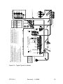
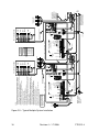
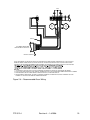
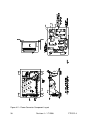
in the red light controller. See Figure
2-5 and Figure 2-6. Verify the
following:
5. If Any Responses are Not Normal:
If any of the responses above are not
exactly as described, proceed to
Troubleshooting.
Intensity stepping is controlled by a
photocell. For testing, the photocell should
be exposed to normal outdoor daylight.
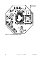
Figure 1-2 gives the location of the
indicator lamps on the board, while Figure
4-1 shows the location of the board within
the power converter.
6. Verify Daytime Operation: Use the
procedure in 1. Check Normal
Daytime Operation for testing the
power converter.
7. Verify Nighttime Operation: Use the
procedure in 2. Check Normal
Nighttime Operation for testing the
power converter.
Troubleshooting
Careful observation of operation often
leads directly to a symptom cause.
System-level problems affect all lights in a
multiple-light system in the same way.
Unit-level problems originate in a single
light.
However,
some
unit-level
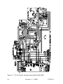
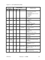
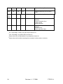
malfunctions can affect the entire multilight system. Use Figure 3-2 for
troubleshooting a single unit and Figure 33 for the system.
•
The system resumes strobe
flashing (at night intensity).
•
The WHT ALM LED (I 8) is not
lit.
When you trace a problem to a specific
component, see Component Testing and
Component Removal and Replacement for
further assistance.
•
The RED ALM LED (I 3) is lit.
Master Unit
•
The alarm circuit operates
according to installation
requirements.
A stand-alone unit is a single FTB 312-4.
A master unit is similar to a stand-alone
unit, except that it is the controlling unit in
a multiple-light system. A master unit has
the photocell connected and, in a multiplelight system, is the controlling unit with
synchronization wires connected at the
4. Restore the Equipment After
Checking: Replace all disconnected
wires. Remove the cover that you
placed on the photocell.
FTB 312-4
Revision 4 – 1-8-2008
31