1
Trigger Coupling Transformer
(T102)
The coupling transformer should not have
open windings. An ohmmeter will indicate
a shorted winding because of the wire size.
Check with an ohmmeter at the wire
terminals.
The general procedure for removing
components follows:
1. Obtain access to the component in
question.
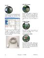
Photocell Testing
Use the following procedure:
•
1. First, disconnect the photocell. The
system should go to night operation
after approximately one minute.
2. If multiple beacon system, disconnect
the master/slave interconnect line on
each power converter.
3. Operate the manual intensity control
switch on each power converter in
turn.
4. If each power converter operates
correctly with the manual intensity
control switch, troubleshoot the
photocell wiring or the circuits in the
erroneously operating power
converter.
5. Reconnect all wires.
During daylight, completely block light
from entering the photocell. If the system
does not enter night mode after a few
minutes, replace the photocell. At night,
shine a light on the photocell, if the system
does not enter day mode after a few
minutes, replace the photocell.
Component Removal and
Replacement
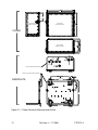
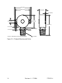
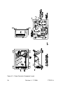
A power converter component location
diagram is provided in Figure 4-1. A
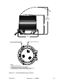
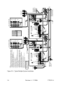
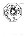
flashhead component location diagram is
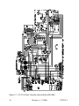
provided in Figure 4-3. A flashhead
electrical wiring diagram is provided in
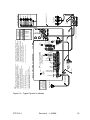
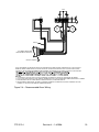
Figure 2-10. A power converter internal
wiring diagram is provided in Figure 2-7.
FTB 312-4
Note the location and color of all wires
that you disconnect. When you replace the
wiring after you replace the components,
ensure that the wiring agrees with Figure
2-7.
Disconnect completely or partially
the wiring to components first that
prevent clear access.
2. Completely remove or relocate these
components.
3. Disconnect the wiring to the
component that you want to replace.
4. Remove this component.
5. Replace everything in the reverse
order: first the component, then the
wiring. In some cases, you may have
to place some wires on the component
before you fasten it in place, then
replace the remaining wires.
Most components are relatively easy to
access for removal. Only those that are
more difficult are described.
Power Converter Components
Capacitors
Before removing or replacing a capacitor
always ensure it is discharged by checking
with a voltmeter directly across the
terminals. Discharge a capacitor by
placing a resistance (25 watts/10,000 ohms
or greater) between its terminals. Direct
shorting may damage the capacitor, and
connecting the terminals to the equipment
chassis may fail to discharge it.
Remove the fuse for this procedure to
prevent application of power if the
interlock switch is accidentally pressed.
Revision 4 – 1-8-2008
25