1
interfere with access by maintenance or
service personnel.
You must use a bonding strap with a
flashhead mounting bolt when mounting
the flashhead to the structure, using the
mounting bolt to fasten the strap to the leg
that contains the ground connection.
Flashhead Leveling
The flashheads must be level for correct
vertical beam alignment. Two leveling
vials—aligned with the mounting feet—
are permanently attached to the flashhead
assembly. Typically, the mounting surface
for the flashhead is level and no
adjustments are required. When the
flashhead is level, bubbles in both leveling
vials are centered. For leveling, use the
following guidelines:
If adjustment is necessary, raise the
appropriate mounting foot with shims or
washers. Raising one foot by 1/16 inch
(1.6 mm) tilts the beam about 1/2 degree.
Take extreme care to ensure that all four
feet rest snugly against a firm mounting
surface before tightening the mounting
bolts. Failure to do so could result in
serious damage to the base when you
tighten the bolts.
Photocell
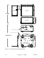
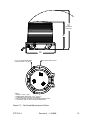
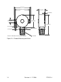
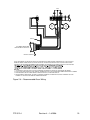
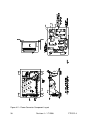
Mounting and outline dimensions for the
photocell are shown in Figure 2-3. The
photocell uses a male 1/2” NPT for
mounting. Use the following guidelines to
mount the photocell:
Locate the photocell where it has an
unobstructed view of the polar sky.
It must not view direct or reflected
artificial light.
The photocell may be supported directly
by electrical conduit.
Ensure that the installation is watertight.
FTB 312-4
Installation
This manual may not contain all the
information about installation wiring
required for your installation.
NOTE
If
installation
drawings
prepared
specifically for your site disagree with
information provided in this manual, the
site installation drawings should take
precedence. Consult any site-specific
installation wiring diagram supplied with
your equipment.
Flash Technology wiring diagrams
define only minimum requirements
recommended
for
satisfactory
equipment
operation.
It
is
the
responsibility of the installer to comply
with all applicable electrical codes.
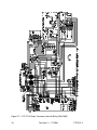
You can find conduit and other
distribution wiring details on electrical
installation diagrams provided by Flash
Technology or others. Installation
instructions concerning red light marker
fixtures are not part of this manual.
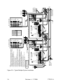
All installation wiring should have an
insulation rating of 600 volts. You must
size power service wiring to satisfy the
load demand of the red light system (if
present) and the power converters. Read
the notes on the installation wiring
diagrams supplied both in this manual and
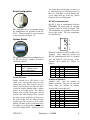
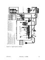
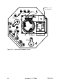
with the equipment. See Figure 2-9 for
information
about
wiring
alarm
connections to the main panel of the power
converter.
Power Converter Wiring
Consult the installation wiring drawings.
For service wiring, consider the voltage,
length of the wire run, and the total load
(number of lights). Assume a load of 175
volt-amperes per light, and do not permit
the line voltage to drop by more than 5%
due to wire resistance. Assume a load of
175 volt-amperes per light to determine
the slow-acting fuse ratings at the power
distribution panel. Use a value of 250 volt-
Revision 4 – 1-8-2008
9