1
Cisco 7100 Series VPN Router Installation
and Configuration Guide
Corporate Headquarters
Cisco Systems, Inc.
170 West Tasman Drive
San Jose, CA 95134-1706
USA
http://www.cisco.com
Tel: 408 526-4000
800 553-NETS (6387)
Fax: 408 526-4100
Customer Order Number: DOC-786341=
Text Part Number: 78-6341-03
THE SPECIFICATIONS AND INFORMATION REGARDING THE PRODUCTS IN THIS MANUAL ARE SUBJECT TO CHANGE WITHOUT NOTICE. ALL
STATEMENTS, INFORMATION, AND RECOMMENDATIONS IN THIS MANUAL ARE BELIEVED TO BE ACCURATE BUT ARE PRESENTED WITHOUT
WARRANTY OF ANY KIND, EXPRESS OR IMPLIED. USERS MUST TAKE FULL RESPONSIBILITY FOR THEIR APPLICATION OF ANY PRODUCTS.
THE SOFTWARE LICENSE AND LIMITED WARRANTY FOR THE ACCOMPANYING PRODUCT ARE SET FORTH IN THE INFORMATION PACKET THAT
SHIPPED WITH THE PRODUCT AND ARE INCORPORATED HEREIN BY THIS REFERENCE. IF YOU ARE UNABLE TO LOCATE THE SOFTWARE LICENSE
OR LIMITED WARRANTY, CONTACT YOUR CISCO REPRESENTATIVE FOR A COPY.
The following information is for FCC compliance of Class A devices: This equipment has been tested and found to comply with the limits for a Class A digital device, pursuant
to part 15 of the FCC rules. These limits are designed to provide reasonable protection against harmful interference when the equipment is operated in a commercial
environment. This equipment generates, uses, and can radiate radio-frequency energy and, if not installed and used in accordance with the instruction manual, may cause
harmful interference to radio communications. Operation of this equipment in a residential area is likely to cause harmful interference, in which case users will be required
to correct the interference at their own expense.
The following information is for FCC compliance of Class B devices: The equipment described in this manual generates and may radiate radio-frequency energy. If it is not
installed in accordance with Cisco’s installation instructions, it may cause interference with radio and television reception. This equipment has been tested and found to
comply with the limits for a Class B digital device in accordance with the specifications in part 15 of the FCC rules. These specifications are designed to provide reasonable
protection against such interference in a residential installation. However, there is no guarantee that interference will not occur in a particular installation.
Modifying the equipment without Cisco’s written authorization may result in the equipment no longer complying with FCC requirements for Class A or Class B digital
devices. In that event, your right to use the equipment may be limited by FCC regulations, and you may be required to correct any interference to radio or television
communications at your own expense.
You can determine whether your equipment is causing interference by turning it off. If the interference stops, it was probably caused by the Cisco equipment or one of its
peripheral devices. If the equipment causes interference to radio or television reception, try to correct the interference by using one or more of the following measures:
• Turn the television or radio antenna until the interference stops.
• Move the equipment to one side or the other of the television or radio.
• Move the equipment farther away from the television or radio.
• Plug the equipment into an outlet that is on a different circuit from the television or radio. (That is, make certain the equipment and the television or radio are on circuits
controlled by different circuit breakers or fuses.)
Modifications to this product not authorized by Cisco Systems, Inc. could void the FCC approval and negate your authority to operate the product.
The Cisco implementation of TCP header compression is an adaptation of a program developed by the University of California, Berkeley (UCB) as part of UCB’s public
domain version of the UNIX operating system. All rights reserved. Copyright © 1981, Regents of the University of California.
NOTWITHSTANDING ANY OTHER WARRANTY HEREIN, ALL DOCUMENT FILES AND SOFTWARE OF THESE SUPPLIERS ARE PROVIDED “AS IS” WITH
ALL FAULTS. CISCO AND THE ABOVE-NAMED SUPPLIERS DISCLAIM ALL WARRANTIES, EXPRESSED OR IMPLIED, INCLUDING, WITHOUT
LIMITATION, THOSE OF MERCHANTABILITY, FITNESS FOR A PARTICULAR PURPOSE AND NONINFRINGEMENT OR ARISING FROM A COURSE OF
DEALING, USAGE, OR TRADE PRACTICE.
IN NO EVENT SHALL CISCO OR ITS SUPPLIERS BE LIABLE FOR ANY INDIRECT, SPECIAL, CONSEQUENTIAL, OR INCIDENTAL DAMAGES, INCLUDING,
WITHOUT LIMITATION, LOST PROFITS OR LOSS OR DAMAGE TO DATA ARISING OUT OF THE USE OR INABILITY TO USE THIS MANUAL, EVEN IF CISCO
OR ITS SUPPLIERS HAVE BEEN ADVISED OF THE POSSIBILITY OF SUCH DAMAGES.
CCIP, CCSP, the Cisco Arrow logo, the Cisco Powered Network mark, the Cisco Systems Verified logo, Cisco Unity, Follow Me Browsing, FormShare, iQ Net Readiness
Scorecard, Networking Academy, and ScriptShare are trademarks of Cisco Systems, Inc.; Changing the Way We Work, Live, Play, and Learn, The Fastest Way to Increase Your
Internet Quotient, and iQuick Study are service marks of Cisco Systems, Inc.; and Aironet, ASIST, BPX, Catalyst, CCDA, CCDP, CCIE, CCNA, CCNP, Cisco, the Cisco Certified
Internetwork Expert logo, Cisco IOS, the Cisco IOS logo, Cisco Press, Cisco Systems, Cisco Systems Capital, the Cisco Systems logo, Empowering the Internet Generation,
Enterprise/Solver, EtherChannel, EtherSwitch, Fast Step, GigaStack, Internet Quotient, IOS, IP/TV, iQ Expertise, the iQ logo, LightStream, MGX, MICA, the Networkers logo,
Network Registrar, Packet, PIX, Post-Routing, Pre-Routing, RateMUX, Registrar, SlideCast, SMARTnet, StrataView Plus, Stratm, SwitchProbe, TeleRouter, TransPath, and VCO
are registered trademarks of Cisco Systems, Inc. and/or its affiliates in the U.S. and certain other countries.
All other trademarks mentioned in this document or Web site are the property of their respective owners. The use of the word partner does not imply a partnership relationship
between Cisco and any other company. (0303R)
Cisco 7100 Series VPN Router Installation and Configuration Guide
Copyright © 2003 Cisco Systems, Inc. All rights reserved.
CONTENTS
Preface
ix
Audience
ix
Installation Warning
ix
Document Organization
xi
Related Documentation
xi
Document Conventions
xv
Terms and Acronyms
xvii
Obtaining Documentation xix
Cisco.com xix
Documentation CD-ROM xix
Ordering Documentation xix
Documentation Feedback xx
Obtaining Technical Assistance xx
Cisco.com xx
Technical Assistance Center xx
Cisco TAC Website xxi
Cisco TAC Escalation Center xxi
Obtaining Additional Publications and Information
CHA PTER
1
Overview
xxi
1-1
Product Description
1-1
Cisco 7120 Series Overview 1-5
Cisco 7120-4T1 1-5
Cisco 7120-T3 1-8
Cisco 7120-E3 1-9
Cisco 7120-AT3, Cisco 7120-AE3, and Cisco 7120-SMI3
1-11
Cisco 7140 Series Overview 1-14
Cisco 7140-2T3 1-14
Cisco 7140-2E3 1-16
Cisco 7140-2AT3, Cisco 7140-2AE3, and Cisco 7140-2MM3
Cisco 7140-8T 1-20
Cisco 7140-2FE 1-22
1-17
Field-Replaceable Units 1-22
Port Adapters 1-23
Cisco 7100 Series VPN Router Installation and Configuration Guide
78-6341-03
iii
Contents
Integrated Service Module (ISM)/Integrated Service Adapter (ISA)
ISM 1-24
ISA 1-25
VPN Acceleration Module (VAM) 1-26
SA-VAM 1-26
SM-VAM 1-27
Flash Disks 1-27
SDRAM Memory 1-28
Rack-Mount and Cable-Management Kit 1-29
1-23
Functional Overview 1-30
Chassis Slot and Logical Interface Numbering 1-30
Interface Information in the Software 1-31
MAC Addresses 1-32
Online Insertion and Removal 1-33
Peripheral Component Interconnect Buses 1-33
Network Processor Card 1-34
System LEDs and Reset Button 1-38
Environmental Monitoring and Reporting Functions 1-39
Environmental Monitoring 1-39
Displaying Environmental Status Reports 1-40
Fan Failures 1-42
CHA PTER
2
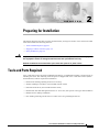
Preparing for Installation
Tools and Parts Required
2-1
2-1
Shipping Container Contents
2-2
Safety Guidelines 2-2
Electrical Equipment Guidelines 2-3
Electrostatic Discharge Prevention 2-4
Chassis Lifting Guidelines 2-5
Site Requirement Guidelines 2-6
Rack-Mounting Guidelines 2-6
Temperature and Humidity Requirements 2-9
Power Connection Guidelines 2-9
Plant Wiring Guidelines 2-10
Interference Considerations 2-10
Distance Limitations and Interface Specifications
Ethernet Connections 2-12
WAN Connections 2-12
Laser and LED Safety Guidelines 2-12
2-11
Cisco 7100 Series VPN Router Installation and Configuration Guide
iv
78-6341-03
Contents
Console and Auxiliary Port Considerations
Console Port Connections 2-13
Auxiliary Port Connections 2-13
CHA PTER
3
Installing a Cisco 7100 VPN Series Router
Setting the Chassis on a Tabletop
2-13
3-1
3-1
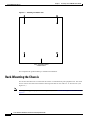
Rack-Mounting the Chassis 3-2
Attaching the Brackets 3-3
Installing the Chassis in a Rack
3-4
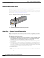
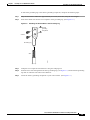
Attaching a System Ground Connection
3-4
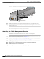
Attaching the Cable-Management Bracket
3-6
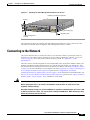
Connecting to the Network 3-7
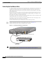
Connecting the Fast Ethernet Ports 3-8
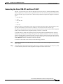
Connecting the Cisco 7120-4T1 and Cisco 7140-8T 3-9
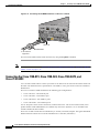
Connecting the Cisco 7120-T3, Cisco 7120-E3, Cisco 7140-2T3, and Cisco 7140-2E3 3-10
Connecting the Cisco 7120-AT3, Cisco 7120-AE3, Cisco 7140-2AT3, and Cisco 7140-2AE3 3-12
Connecting the Cisco 7120-SMI3 and Cisco 7140-2MM3 3-14
Connecting the Console Port and Auxiliary Port
Connecting to the Console Port 3-16
Connecting a Modem to the Auxiliary Port
Connecting the Power
CHA PTER
4
3-16
3-17
3-18
Performing a Basic Startup Configuration
Checking Conditions Prior to System Startup
4-1
4-1
Starting the System and Observing Initial Conditions
4-1
Configuring a Router 4-3
Performing a Basic Configuration Using AutoInstall 4-3
Performing a Basic Configuration Using the Setup Facility 4-4
Performing a Basic Configuration Using Global Configuration Mode
Using the EXEC Command Interpreter 4-8
Configuring the Fast Ethernet Interfaces 4-9
Configuring the T1 and E1 Interfaces 4-10
Configuring the T3 Interfaces 4-11
Configuring the E3 Interfaces 4-13
Configuring the ATM Interfaces 4-15
4-7
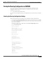
Saving the Running Configuration to NVRAM 4-17
Checking the Running Configuration Settings 4-17
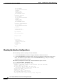
Checking the Interface Configurations 4-18
Cisco 7100 Series VPN Router Installation and Configuration Guide
78-6341-03
v
Contents
Performing Other Configuration Tasks
Viewing the System Configuration
4-19
4-19
Replacing or Recovering a Lost Password 4-21
Overview of the Password Recovery Procedure 4-21
Details of the Password Recovery Procedure 4-22
CHA PTER
Troubleshooting the Installation
5
5-1
Troubleshooting Overview 5-1
Before You Call for Technical Assistance 5-1
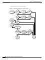
Problem Solving Using a Subsystems Approach
Identifying Startup Problems 5-3
Troubleshooting the Power Subsystem
5-3
5-4
Troubleshooting the Processor Subsystem 5-4
Troubleshooting the Network Processor Card 5-5
Troubleshooting the Port Adapter and Fixed WAN Ports
Troubleshooting the Cooling Subsystem
5-5
5-6
APPENDIX
A
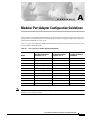
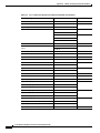
Modular Port Adapter Configuration Guidelines
APPENDIX
B
System Specifications
APPENDIX
C
Cable Specifications
A-1
B-1
C-1
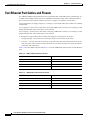
Console and Auxiliary Port Cables and Pinouts
Identifying a Rollover Cable C-2
Console Port Cables and Pinouts C-2
Auxiliary Port Cables and Pinouts C-3
Fast Ethernet Port Cables and Pinouts
C-1
C-4
Cisco 7120-4T1 and Cisco 7140-8T Cables and Pinouts
EIA/TIA-232 Connections C-8
EIA/TIA-449 Connections C-10
V.35 Connections C-12
X.21 Connections C-15
EIA-530 Connections C-16
C-5
Cisco 7120-T3, Cisco 7120-E3, Cisco 7140-2T3, and Cisco 7140-2E3 Cables
C-18
Cisco 7120-AT3, Cisco 7140-2AT3, Cisco 7120-AE3, Cisco 7140-2AE3, Cisco 7120-SMI3, and
Cisco 7140-2MM3 Cables C-19
AT3 and AE3 Cables and Receptacles C-20
MM3 and SMI3 Cables and Receptacles C-21
Cisco 7100 Series VPN Router Installation and Configuration Guide
vi
78-6341-03
Contents
Fiber-Optic Transmission Specifications C-22
SONET Distance Limitations C-22
Power Budget C-22
Approximating the MM3 and SMI3 Port Power Margin C-23
Multimode Power Budget Example with Sufficient Power for Transmission
Multimode Power Budget Example of Dispersion Limit C-24
Single-Mode Transmission C-25
SONET Single-Mode Power Budget Example C-25
Using Statistics to Estimate the Power Budget C-25
C-24
INDEX
Cisco 7100 Series VPN Router Installation and Configuration Guide
78-6341-03
vii
Contents
Cisco 7100 Series VPN Router Installation and Configuration Guide
viii
78-6341-03
Preface
This installation guide explains the initial hardware installation and basic configuration procedures for
the Cisco 7100 series VPN router.
This preface contains the following sections:
•
Audience, page ix
•
Installation Warning, page ix
•
Document Organization, page xi
•
Related Documentation, page xi
•
Document Conventions, page xv
•
Terms and Acronyms, page xvii
•
Obtaining Documentation, page xix
•
Obtaining Technical Assistance, page xx
•
Obtaining Additional Publications and Information, page xxi
Audience
To use this publication, you should be familiar not only with Cisco router hardware and cabling but also
with electronic circuitry and wiring practices. You should also have experience as an electronic or
electromechanical technician.
Installation Warning
Warning
Waarschuwing
Only trained and qualified personnel should be allowed to install, replace, or service
this equipment.
Deze apparatuur mag alleen worden geïnstalleerd, vervangen of hersteld door bevoegd
geschoold personeel.
Cisco 7100 Series VPN Router Installation and Configuration Guide
78-6341-03
ix
Preface
Installation Warning
Varoitus
Tämän laitteen saa asentaa, vaihtaa tai huoltaa ainoastaan koulutettu ja laitteen
tunteva henkilökunta.
Attention
Il est vivement recommandé de confier l'installation, le remplacement et la maintenance de ces
équipements à des personnels qualifiés et expérimentés.
Warnung
Das Installieren, Ersetzen oder Bedienen dieser Ausrüstung sollte nur geschultem, qualifiziertem
Personal gestattet werden.
Figyelem!
A berendezést csak szakképzett személyek helyezhetik üzembe, cserélhetik és tarthatják karban.
Avvertenza
Advarsel
Aviso
¡Advertencia!
Varning!
Questo apparato può essere installato, sostituito o mantenuto unicamente da un personale
competente.
Bare opplært og kvalifisert personell skal foreta installasjoner, utskiftninger eller service på
dette utstyret.
Apenas pessoal treinado e qualificado deve ser autorizado a instalar, substituir ou fazer a revisão
deste equipamento.
Solamente el personal calificado debe instalar, reemplazar o utilizar este equipo.
Endast utbildad och kvalificerad personal bör få tillåtelse att installera, byta ut eller reparera
denna utrustning.
Cisco 7100 Series VPN Router Installation and Configuration Guide
x
78-6341-03
Preface
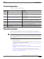
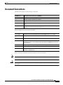
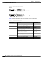
Document Organization
Document Organization
The major sections of this guide are as follows:
Chapter
Title
Description
1
Overview
Physical properties and functional overview of Cisco 7100
series VPN routers.
2
Preparing for Installation
Safety considerations, tools required, an overview of the
installation, and procedures you should perform before the
actual installation.
3
Installing a Cisco 7100 VPN Series Router
Installing the hardware and connecting the external network
interface cables.
4
Performing a Basic Startup Configuration
Procedures for completing a basic system configuration and for
checking and saving this configuration to system memory.
5
Troubleshooting the Installation
Basic troubleshooting procedures for the hardware installation.
A
Modular Port Adapter Configuration Guidelines Bandwidth specifications and guidelines for installing port
adapters in Cisco 7100 series VPN routers.
B
System Specifications
Physical specifications and power requirements of the router.
C
Cable Specifications
Cabling information and pinout information for the router.
Related Documentation
This section lists documentation related to your router and its functionality. The documentation
mentioned is available online at Cisco.com, page xx, and on the Documentation CD-ROM, page xix.
Note
We no longer ship the entire router documentation set automatically with each system. You must
specifically order the documentation as part of the sales order. If you ordered documentation and did not
receive it, we will ship the documents to you within 24 hours. To order documents, contact a customer
service representative.
•
For hardware installation and maintenance information for the Cisco 7100 series VPN routers, refer
to the following documents:
– For a complete list of Cisco series router hardware documentation, refer to the Cisco 7100 Series
VPN Router Documentation flyer—DOC-7814391=
http://www.cisco.com/en/US/products/hw/vpndevc/ps333/products_product_index09186a008
00fa142.html
– Cisco 7100 Series VPN Quick Start Guide—DOC-786343=
http://www.cisco.com/en/US/products/hw/vpndevc/ps333/products_quick_start09186a00800a
8557.html
– Cisco 7100 Series VPN Router Installation and Configuration Guide—DOC-786341=
http://www.cisco.com/en/US/products/hw/vpndevc/ps333/products_installation_and_configur
ation_guide_book09186a008007cbe6.html
Cisco 7100 Series VPN Router Installation and Configuration Guide
78-6341-03
xi
Preface
Related Documentation
– Cisco 7100 Series VPN Router Regulatory Compliance and Safety
Information—DOC-786345=
http://www.cisco.com/en/US/products/hw/vpndevc/ps333/products_regulatory_approvals_and
_compliance09186a0080119622.html
– Installing Field-Replaceable Units—DOC-786344=
http://www.cisco.com/en/US/products/hw/vpndevc/ps333/prod_installation_guide09186a0080
07db0a.html
– Installing and Removing the Boot ROM in Cisco 7100 Series Routers—DOC-7810156=
http://www.cisco.com/en/US/products/hw/vpndevc/ps333/prod_installation_guide09186a0080
09b16e.html
– Installing and Removing the Power Supply in Cisco 7100 Series Routers—DOC-7810417=
http://www.cisco.com/en/US/products/hw/vpndevc/ps333/prod_installation_guide09186a0080
07db0b.html
– Integrated Service Adapter and Integrated Service Module Installation and Configuration
http://www.cisco.com/en/US/products/hw/modules/ps2957/products_module_installation_gui
de_book09186a008007dc9d.html
– VPN Acceleration Module (VAM) Installation and Configuration Guide
http://www.cisco.com/en/US/products/hw/routers/ps341/products_module_installation_guide
_book09186a008010dfeb.html
– Cisco 7100 series VPN router troubleshooting information:
http://www.cisco.com/en/US/products/hw/vpndevc/ps333/prod_troubleshooting_technique09
186a008014db1c.html
– Cisco 7100 Tech Notes:
http://www.cisco.com/en/US/products/hw/vpndevc/ps333/prod_tech_notes_list.html
•
Note
•
Note
Port Adapter Installation and Configuration guides, available online at:
http://www.cisco.com/en/US/products/hw/modules/ps2033/prod_module_installation_guides_list.
html
and
http://www.cisco.com/en/US/products/hw/modules/ps2033/products_module_installation_guides_
books_list.html
For specific port and service adapters for the Cisco 7100 series VPN routers, see the Cisco 7100
Series VPN Router Documentation flyer—DOC-7814391=
http://www.cisco.com/en/US/products/hw/vpndevc/ps333/products_product_index09186a0080
0fa142.html.
For configuration information and support, refer to the modular configuration and modular
command reference publications in the Cisco IOS software configuration documentation set that
corresponds to the software release installed on your Cisco hardware. Access these documents at:
http://www.cisco.com/en/US/products/sw/iosswrel/index.html.
Select Translated documentation is available at http://www.cisco.com/ by selecting the topic
‘Select a Location / Language’ at the top of the page.
Cisco 7100 Series VPN Router Installation and Configuration Guide
xii
78-6341-03
Preface
Related Documentation
– To determine the minimum Cisco IOS software requirements for your router, Cisco maintains
the Software Advisor tool on Cisco.com. This tool does not verify whether modules within a
system are compatible, but it does provide the minimum IOS requirements for individual
hardware modules or components. Registered Cisco Direct users can access the Software
Advisor at: http://www.cisco.com/cgi-bin/Support/CompNav/Index.pl.
•
For IP security and encryption:
– Cisco IOS Enterprise VPN Configuration Guide—DOC-786342=
http://www.cisco.com/en/US/products/hw/vpndevc/ps333/products_configuration_guide_boo
k09186a008007dcb2.html
– Cisco IOS Interface Configuration Guide, Release 12.1
http://www.cisco.com/en/US/products/sw/iosswrel/ps1831/products_configuration_guide_boo
k09186a0080088071.html
– Cisco IOS Interface Command Reference, Release 12.1
http://www.cisco.com/en/US/products/sw/iosswrel/ps1831/products_command_reference_boo
k09186a00800880d1.html
– Cisco IOS Security Configuration Guide, Release 12.2
http://www.cisco.com/en/US/partner/products/sw/iosswrel/ps1835/products_configuration_gu
ide_book09186a0080087df1.html
– Cisco IOS Security Command Reference, Release 12.2
http://www.cisco.com/en/US/partner/products/sw/iosswrel/ps1835/products_command_refere
nces_books_list.html
– Cisco IOS Security Configuration Guide, Release 12.1
http://www.cisco.com/en/US/partner/products/sw/iosswrel/ps1831/products_configuration_gu
ide_book09186a0080088254.html
– Cisco IOS Security Command Reference, Release 12.1
http://www.cisco.com/en/US/partner/products/sw/iosswrel/ps1831/products_command_refere
nces_books_list.html
– Cisco IOS Release 12.0 Security Configuration Guide
http://www.cisco.com/en/US/partner/products/sw/iosswrel/ps1828/products_configuration_gu
ides_books_list.html
– Cisco IOS Release 12.0 Security Command Reference
http://www.cisco.com/en/US/partner/products/sw/iosswrel/ps1828/products_command_refere
nces_books_list.html
– Cisco IOS Quality of Service Solutions Configuration Guide, Release 12.2
http://www.cisco.com/en/US/products/sw/iosswrel/ps1835/products_configuration_guide_boo
k09186a00800c5e31.html
– Cisco IOS Quality of Service Solutions Configuration Guide, Release 12.1
http://www.cisco.com/en/US/products/sw/iosswrel/ps1831/products_configuration_guide_boo
k09186a008007ff1d.html
– Cisco IOS Release 12.0 Quality of Service Solutions Configuration Guide
http://www.cisco.com/en/US/products/sw/iosswrel/ps1828/products_configuration_guide_boo
k09186a0080087c70.html
– Cisco IOS Interface Configuration Guide, Release 12.1
http://www.cisco.com/en/US/products/sw/iosswrel/ps1831/products_configuration_guide_boo
k09186a0080088071.html
Cisco 7100 Series VPN Router Installation and Configuration Guide
78-6341-03
xiii
Preface
Related Documentation
– For FIPS 140 Security documents:
http://www.cisco.com/en/US/partner/products/hw/routers/ps341/products_regulatory_approva
ls_and_compliance09186a00800f009e.html
– For the VPN Device Manager documents:
http://www.cisco.com/en/US/partner/products/sw/cscowork/ps2322/products_release_and_ins
tallation_notes_list.html
•
If you are a registered Cisco Direct Customer, you can access the following tools:
– Tools, Maintenance, and Troubleshooting Tips for Cisco IOS Software for Cisco IOS
Release 12.0
http://www.cisco.com/en/US/products/sw/iosswrel/ps1828/prod_troubleshooting_technique09
186a008010929b.html
– Tools, Maintenance, and Troubleshooting Tips for Cisco IOS Software for Cisco IOS
Release 12.1
http://www.cisco.com/en/US/products/sw/iosswrel/ps1831/prod_troubleshooting_technique09
186a0080107cc7.html
– Tools, Maintenance, and Troubleshooting Tips for Cisco IOS Software for Cisco IOS
Release 12.2
http://www.cisco.com/en/US/products/sw/iosswrel/ps1835/prod_troubleshooting_technique09
186a00800f9050.html
– Software Advisor
http://www.cisco.com/en/US/partner/support/index.html
– Bug Toolkit
http://www.cisco.com/en/US/partner/products/hw/routers/ps341/prod_bug_toolkit.html
– Bug Navigator
http://www.cisco.com/cgi-bin/Support/Bugtool/launch_bugtool.pl
– Feature Navigator
http://www.cisco.com/en/US/partner/products/prod_feature_navigator_for_cisco_IOS_tool_la
unch.html
– Output Interpreter
https://www.cisco.com/cgi-bin/Support/OutputInterpreter/home.pl
– Cisco IOS Error Message Decoder
http://www.cisco.com/cgi-bin/Support/Errordecoder/home.pl
– Cisco Dynamic Configuration Tool
http://www.cisco.com/en/US/ordering/or13/or8/ordering_ordering_help_dynamic_configurati
on_tool_launch.html
– MIB Locator
http://tools.cisco.com/ITDIT/MIBS/servlet/index
•
Additional tools include:
– Tools Index
http://www.cisco.com/en/US/partner/products/prod_tools_index.html
– Cisco IOS Software Selector Tool
http://tools.cisco.com/ITDIT/ISTMAIN/servlet/index
Cisco 7100 Series VPN Router Installation and Configuration Guide
xiv
78-6341-03
Preface
Document Conventions
Document Conventions
Command descriptions use the following conventions:
boldface font
Commands and keywords are in boldface.
italic font
Arguments for which you supply values are in italics.
[ ]
Elements in square brackets are optional.
{x|y|z}
Alternative keywords are grouped in braces and separated by vertical bars.
[x|y|z]
Optional alternative keywords are grouped in brackets and separated by vertical
bars.
string
A nonquoted set of characters. Do not use quotation marks around the string, or
the string will include the quotation marks.
Screen examples use the following conventions:
screen
font
boldface screen
Terminal sessions and information the system displays are in screen font.
Information you must enter is in boldface screen font.
font
italic screen font
Arguments for which you supply values are in italic screen font.
^
The symbol ^ represents the key labeled Control—for example, the key
combination ^D in a screen display means hold down the Control key while you
press the D key.
< >
Nonprinting characters, such as passwords, are in angle brackets.
[ ]
Default responses to system prompts are in square brackets.
!, #
An exclamation point (!) or a pound sign (#) at the beginning of a line of code
indicates a comment line.
Notes, cautionary statements, and safety warnings use these conventions:
Note
Caution
Means reader take note. Notes contain helpful suggestions or references to materials not contained in
this manual.
Means reader be careful. You are capable of doing something that might result in equipment damage or
loss of data.
Cisco 7100 Series VPN Router Installation and Configuration Guide
78-6341-03
xv
Preface
Document Conventions
Warning
This warning symbol means danger. You are in a situation that could cause bodily injury. Before
you work on any equipment, be aware of the hazards involved with electrical circuitry and be
familiar with standard practices for preventing accidents. To see translations of the warnings
that appear in this publication, refer to the Regulatory Compliance and Safety Information
document that accompanied this device.
Waarschuwing
Dit waarschuwingssymbool betekent gevaar. U verkeert in een situatie die lichamelijk letsel
kan veroorzaken. Voordat u aan enige apparatuur gaat werken, dient u zich bewust te zijn van
de bij elektrische schakelingen betrokken risico's en dient u op de hoogte te zijn van standaard
maatregelen om ongelukken te voorkomen. Voor vertalingen van de waarschuwingen die in
deze publicatie verschijnen, kunt u het document Regulatory Compliance and Safety Information
(Informatie over naleving van veiligheids- en andere voorschriften) raadplegen dat bij dit
toestel is ingesloten.
Varoitus
Tämä varoitusmerkki merkitsee vaaraa. Olet tilanteessa, joka voi johtaa ruumiinvammaan.
Ennen kuin työskentelet minkään laitteiston parissa, ota selvää sähkökytkentöihin liittyvistä
vaaroista ja tavanomaisista onnettomuuksien ehkäisykeinoista. Tässä julkaisussa esiintyvien
varoitusten käännökset löydät laitteen mukana olevasta Regulatory Compliance and Safety
Information -kirjasesta (määräysten noudattaminen ja tietoa turvallisuudesta).
Attention
Ce symbole d'avertissement indique un danger. Vous vous trouvez dans une situation pouvant
causer des blessures ou des dommages corporels. Avant de travailler sur un équipement, soyez
conscient des dangers posés par les circuits électriques et familiarisez-vous avec les
procédures couramment utilisées pour éviter les accidents. Pour prendre connaissance des
traductions d’avertissements figurant dans cette publication, consultez le document Regulatory
Compliance and Safety Information (Conformité aux règlements et consignes de sécurité) qui
accompagne cet appareil.
Warnung
Dieses Warnsymbol bedeutet Gefahr. Sie befinden sich in einer Situation, die zu einer
Körperverletzung führen könnte. Bevor Sie mit der Arbeit an irgendeinem Gerät beginnen, seien
Sie sich der mit elektrischen Stromkreisen verbundenen Gefahren und der Standardpraktiken
zur Vermeidung von Unfällen bewußt. Übersetzungen der in dieser Veröffentlichung enthaltenen
Warnhinweise finden Sie im Dokument Regulatory Compliance and Safety Information
(Informationen zu behördlichen Vorschriften und Sicherheit), das zusammen mit diesem Gerät
geliefert wurde.
Avvertenza
Questo simbolo di avvertenza indica un pericolo. La situazione potrebbe causare infortuni alle
persone. Prima di lavorare su qualsiasi apparecchiatura, occorre conoscere i pericoli relativi
ai circuiti elettrici ed essere al corrente delle pratiche standard per la prevenzione di incidenti.
La traduzione delle avvertenze riportate in questa pubblicazione si trova nel documento
Regulatory Compliance and Safety Information (Conformità alle norme e informazioni sulla
sicurezza) che accompagna questo dispositivo.
Advarsel
Dette varselsymbolet betyr fare. Du befinner deg i en situasjon som kan føre til personskade. Før
du utfører arbeid på utstyr, må du vare oppmerksom på de faremomentene som elektriske kretser
innebærer, samt gjøre deg kjent med vanlig praksis når det gjelder å unngå ulykker. Hvis du vil
se oversettelser av de advarslene som finnes i denne publikasjonen, kan du se i dokumentet
Regulatory Compliance and Safety Information (Overholdelse av forskrifter og
sikkerhetsinformasjon) som ble levert med denne enheten.
Cisco 7100 Series VPN Router Installation and Configuration Guide
xvi
78-6341-03
Preface
Terms and Acronyms
Aviso
¡Advertencia!
Este símbolo de aviso indica perigo. Encontra-se numa situação que lhe poderá causar danos
físicos. Antes de começar a trabalhar com qualquer equipamento, familiarize-se com os perigos
relacionados com circuitos eléctricos, e com quaisquer práticas comuns que possam prevenir
possíveis acidentes. Para ver as traduções dos avisos que constam desta publicação, consulte
o documento Regulatory Compliance and Safety Information (Informação de Segurança e
Disposições Reguladoras) que acompanha este dispositivo.
Este símbolo de aviso significa peligro. Existe riesgo para su integridad física. Antes de manipular
cualquier equipo, considerar los riesgos que entraña la corriente eléctrica y familiarizarse con los
procedimientos estándar de prevención de accidentes. Para ver una traducción de las advertencias
que aparecen en esta publicación, consultar el documento titulado Regulatory Compliance and
Safety Information (Información sobre seguridad y conformidad con las disposiciones
reglamentarias) que se acompaña con este dispositivo.
Terms and Acronyms
To fully understand the content of this guide, you should be familiar with the following terms and
acronyms:
•
ABR—Available bit rate
•
AAL5—ATM adaptation layer 5
•
ATM-DXI—Asynchronous Transfer Mode-Data Exchange Interface
•
AWG—American wire gauge
•
CoS—Class of service
•
CPE—Customer premises equipment
•
CRC—Cyclic redundancy check
•
CSU—Channel service unit
•
CTS—Clear To Send
•
DCD—Data Carrier Detect
•
DCE—Data communications equipment
•
DIMM—Dual in-line memory module
•
DSR—Data set ready
•
DSU—Data service unit
•
DTE—Data terminal equipment
•
DTR—Data terminal ready
•
EMC—Electromagnetic compliance
•
EMI—Electromagnetic interference
•
ESD—Electrostatic discharge
•
FRU—Field-replaceable unit (router components that do not require replacement by a
Cisco-certified service provider)
•
FTP—Foil twisted-pair
•
HDLC—High-Level Data Link Control
Cisco 7100 Series VPN Router Installation and Configuration Guide
78-6341-03
xvii
Preface
Terms and Acronyms
•
IGRP—Interior Gateway Routing Protocol
•
ILMI—Integrated Local Management Interface
•
IPSec—IP Security Protocol
•
ISM—Integrated Service Module
•
L2F/L2TP—Layer 2 Forwarding and Layer 2 Tunneling Protocol
•
LANE—LAN emulation
•
MAC—Media Access Control
•
MB—Megabyte
•
MM—Multimode
•
nrt-VBR—Non-real time variable bit rate
•
NVRAM—Nonvolatile random-access memory
•
OAM AIS—Operation, Administration, and Maintenance alarm indication signal
•
OIR—Online insertion and removal
•
PCI—Peripheral Component Interconnect
•
PCMCIA—Personal Computer Memory Card International Association
•
PPP—Point-to-Point Protocol
•
QoS—Quality of service
•
rcp—remote copy protocol
•
RFI—Radio frequency interference
•
RIP—Routing Information Protocol
•
RISC—Reduced Instruction Set Computing
•
RTS—Request To Send
•
SAR—Segmentation and reassembly
•
SDRAM—Synchronous dynamic random-access memory
•
SIMM—Single in-line memory module
•
SMDS—Switched Multimegabit Data Service
•
SMI—Single-mode intermediate reach
•
SNMP—Simple Network Management Protocol
•
TCP/IP—Transmission Control Protocol/Internet Protocol
•
TDM—Time-division multiplexing
•
TFTP—Trivial File Transfer Protocol
•
UBR—Unspecified bit rate
•
UDP—User Datagram Protocol
•
UNI—User-Network Interface
•
UTP—Unshielded twisted-pair
•
VC—Virtual circuit
•
VPN—Virtual Private Network
Cisco 7100 Series VPN Router Installation and Configuration Guide
xviii
78-6341-03
Preface
Obtaining Documentation
Obtaining Documentation
Cisco provides several ways to obtain documentation, technical assistance, and other technical
resources. These sections explain how to obtain technical information from Cisco Systems.
Cisco.com
You can access the most current Cisco documentation on the World Wide Web at this URL:
http://www.cisco.com/univercd/home/home.htm
You can access the Cisco website at this URL:
http://www.cisco.com
International Cisco web sites can be accessed from this URL:
http://www.cisco.com/public/countries_languages.shtml
Documentation CD-ROM
Cisco documentation and additional literature are available in a Cisco Documentation CD-ROM
package, which may have shipped with your product. The Documentation CD-ROM is updated monthly
and may be more current than printed documentation. The CD-ROM package is available as a single unit
or through an annual subscription.
Registered Cisco.com users can order the Documentation CD-ROM (product number
DOC-CONDOCCD=) through the online Subscription Store:
http://www.cisco.com/go/subscription
Ordering Documentation
You can find instructions for ordering documentation at this URL:
http://www.cisco.com/univercd/cc/td/doc/es_inpck/pdi.htm
You can order Cisco documentation in these ways:
•
Registered Cisco.com users (Cisco direct customers) can order Cisco product documentation from
the Networking Products MarketPlace:
http://www.cisco.com/en/US/partner/ordering/index.shtml
•
Registered Cisco.com users can order the Documentation CD-ROM (Customer Order Number
DOC-CONDOCCD=) through the online Subscription Store:
http://www.cisco.com/go/subscription
•
Nonregistered Cisco.com users can order documentation through a local account representative by
calling Cisco Systems Corporate Headquarters (California, U.S.A.) at 408 526-7208 or, elsewhere
in North America, by calling 800 553-NETS (6387).
Cisco 7100 Series VPN Router Installation and Configuration Guide
78-6341-03
xix
Preface
Obtaining Technical Assistance
Documentation Feedback
You can submit comments electronically on Cisco.com. On the Cisco Documentation home page, click
Feedback at the top of the page.
You can e-mail your comments to [email protected].
You can submit your comments by mail by using the response card behind the front cover of your
document or by writing to the following address:
Cisco Systems
Attn: Customer Document Ordering
170 West Tasman Drive
San Jose, CA 95134-9883
We appreciate your comments.
Obtaining Technical Assistance
Cisco provides Cisco.com, which includes the Cisco Technical Assistance Center (TAC) Website, as a
starting point for all technical assistance. Customers and partners can obtain online documentation,
troubleshooting tips, and sample configurations from the Cisco TAC website. Cisco.com registered
users have complete access to the technical support resources on the Cisco TAC website, including TAC
tools and utilities.
Cisco.com
Cisco.com offers a suite of interactive, networked services that let you access Cisco information,
networking solutions, services, programs, and resources at any time, from anywhere in the world.
Cisco.com provides a broad range of features and services to help you with these tasks:
•
Streamline business processes and improve productivity
•
Resolve technical issues with online support
•
Download and test software packages
•
Order Cisco learning materials and merchandise
•
Register for online skill assessment, training, and certification programs
To obtain customized information and service, you can self-register on Cisco.com at this URL:
http://www.cisco.com
Technical Assistance Center
The Cisco TAC is available to all customers who need technical assistance with a Cisco product,
technology, or solution. Two levels of support are available: the Cisco TAC website and the Cisco TAC
Escalation Center. The avenue of support that you choose depends on the priority of the problem and the
conditions stated in service contracts, when applicable.
We categorize Cisco TAC inquiries according to urgency:
•
Priority level 4 (P4)—You need information or assistance concerning Cisco product capabilities,
product installation, or basic product configuration.
Cisco 7100 Series VPN Router Installation and Configuration Guide
xx
78-6341-03
Preface
Obtaining Additional Publications and Information
•
Priority level 3 (P3)—Your network performance is degraded. Network functionality is noticeably
impaired, but most business operations continue.
•
Priority level 2 (P2)—Your production network is severely degraded, affecting significant aspects
of business operations. No workaround is available.
•
Priority level 1 (P1)—Your production network is down, and a critical impact to business operations
will occur if service is not restored quickly. No workaround is available.
Cisco TAC Website
You can use the Cisco TAC website to resolve P3 and P4 issues yourself, saving both cost and time. The
site provides around-the-clock access to online tools, knowledge bases, and software. To access the
Cisco TAC website, go to this URL:
http://www.cisco.com/tac
All customers, partners, and resellers who have a valid Cisco service contract have complete access to
the technical support resources on the Cisco TAC website. Some services on the Cisco TAC website
require a Cisco.com login ID and password. If you have a valid service contract but do not have a login
ID or password, go to this URL to register:
http://tools.cisco.com/RPF/register/register.do
If you are a Cisco.com registered user, and you cannot resolve your technical issues by using the Cisco
TAC website, you can open a case online at this URL:
http://www.cisco.com/en/US/support/index.html
If you have Internet access, we recommend that you open P3 and P4 cases through the Cisco TAC
website so that you can describe the situation in your own words and attach any necessary files.
Cisco TAC Escalation Center
The Cisco TAC Escalation Center addresses priority level 1 or priority level 2 issues. These
classifications are assigned when severe network degradation significantly impacts business operations.
When you contact the TAC Escalation Center with a P1 or P2 problem, a Cisco TAC engineer
automatically opens a case.
To obtain a directory of toll-free Cisco TAC telephone numbers for your country, go to this URL:
http://www.cisco.com/warp/public/687/Directory/DirTAC.shtml
Before calling, please check with your network operations center to determine the level of Cisco support
services to which your company is entitled: for example, SMARTnet, SMARTnet Onsite, or Network
Supported Accounts (NSA). When you call the center, please have available your service agreement
number and your product serial number.
Obtaining Additional Publications and Information
Information about Cisco products, technologies, and network solutions is available from various online
and printed sources.
•
The Cisco Product Catalog describes the networking products offered by Cisco Systems as well as
ordering and customer support services. Access the Cisco Product Catalog at this URL:
http://www.cisco.com/en/US/products/products_catalog_links_launch.html
Cisco 7100 Series VPN Router Installation and Configuration Guide
78-6341-03
xxi
Preface
Obtaining Additional Publications and Information
•
Cisco Press publishes a wide range of networking publications. Cisco suggests these titles for new
and experienced users: Internetworking Terms and Acronyms Dictionary, Internetworking
Technology Handbook, Internetworking Troubleshooting Guide, and the Internetworking Design
Guide. For current Cisco Press titles and other information, go to Cisco Press online at this URL:
http://www.ciscopress.com
•
Packet magazine is the Cisco monthly periodical that provides industry professionals with the latest
information about the field of networking. You can access Packet magazine at this URL:
http://www.cisco.com/en/US/about/ac123/ac114/about_cisco_packet_magazine.html
•
iQ Magazine is the Cisco monthly periodical that provides business leaders and decision makers
with the latest information about the networking industry. You can access iQ Magazine at this URL:
http://business.cisco.com/prod/tree.taf%3fasset_id=44699&public_view=true&kbns=1.html
•
Internet Protocol Journal is a quarterly journal published by Cisco Systems for engineering
professionals involved in the design, development, and operation of public and private internets and
intranets. You can access the Internet Protocol Journal at this URL:
http://www.cisco.com/en/US/about/ac123/ac147/about_cisco_the_internet_protocol_journal.html
•
Training—Cisco offers world-class networking training, with current offerings in network training
listed at this URL:
http://www.cisco.com/en/US/learning/le31/learning_recommended_training_list.html
Cisco 7100 Series VPN Router Installation and Configuration Guide
xxii
78-6341-03
C H A P T E R
1
Overview
This chapter provides physical and functional overviews of Cisco 7100 series VPN routers and contains
the following sections that describe router hardware, major components, and functions of
hardware-related features:
•
Product Description, page 1-1
•
Cisco 7120 Series Overview, page 1-5
•
Cisco 7140 Series Overview, page 1-14
•
Field-Replaceable Units, page 1-22
•
Functional Overview, page 1-30
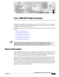
Product Description
Cisco 7100 series VPN routers support Virtual Private Networks (VPNs) and provide an integrated
solution for security, quality of service (QoS), and service-level validation with emphasis on network
technologies such as encryption and tunneling using IP Security (IPSec), Layer 2 Tunneling Protocol
(L2TP), Generic Routing Encapsulation (GRE), and Layer 2 Forwarding (L2F) tunneling to ensure
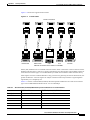
private transactions over public data networks. Cisco 7100 series VPN routers are designed for the
enterprise WAN edge market and customer premises equipment (CPE) for the service provider as shown
in Figure 1-1.
Note
For more information on VPN software features, refer to the Cisco 7100 Series VPN Configuration
Guide available online and on the Documentation CD.
Cisco 7100 Series VPN Router Installation and Configuration Guide
78-6341-03
1-1
Chapter 1
Overview
Product Description
Figure 1-1
Cisco 7100 Series Routers in a Virtual Private Network
Remote
office
Cisco 7100
series router
Tunnels
Main office
Cisco 7100
series router
Remote
office
18484
Internet/IP
Service provider network
Cisco 7100
series router
Cisco 7100 series VPN routers include the following:
•
Cisco 7120 series—Provides one fixed WAN port, two fixed 10BaseT/100BaseTX Fast Ethernet
ports, one modular port adapter slot, and one service module slot.
•
Cisco 7140 series—Provides two fixed WAN ports, two fixed 10BaseT/100BaseTX Fast Ethernet
LAN ports, one modular port adapter slot, and one service module slot.
The Cisco 7120 series is available in six models, and the Cisco 7140 series is available in five models.
The models are defined by the WAN interface.
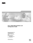
Figure 1-2 shows the front of a Cisco 7100 series VPN router. The front of the router is the same on both
Cisco 7120 series and Cisco 7140 series routers. The specific model number is located on the back of
each unit.
Cisco 7100 Series—Front View
Cisco 7100 SERIES
18481
Figure 1-2
Cisco 7100 series VPN routers support the following features:
•
Online insertion and removal (OIR)—Allows you to add, replace, or remove a modular port adapter
without interrupting the system.
•
Environmental monitoring and reporting functions—Allow you to maintain normal system
operation by resolving adverse environmental conditions prior to loss of operation.
Cisco 7100 Series VPN Router Installation and Configuration Guide
1-2
78-6341-03
Chapter 1
Overview
Product Description
•
Downloadable software—Allows you to load new images into Flash memory remotely, without
having to physically access the router, for fast, reliable upgrades.
•
Network management—Allows you to remotely manage the router. Cisco 7100 series VPN routers
support CiscoWorks and CiscoView network management software.
– CiscoWorks—Lets you monitor complex internetworks that use Cisco routing devices and
helps you plan, troubleshoot, and analyze your network. CiscoWorks uses the Simple Network
Management Protocol (SNMP) to monitor and control any SNMP device on the network.
– CiscoView—A graphical SNMP-based device management tool that provides powerful
real-time views of your networked Cisco devices. These views deliver a continuously updated
physical picture of device configuration and performance conditions, with simultaneous views
available for multiple device sessions. CiscoView runs from a centralized network management
site from which you can review, reconfigure, and monitor essential device data from a simple
GUI (that displays information such as dynamic status reports, performance statistics, and
network inquiries) without having to physically check connections for each device, module, or
port at every different or remote location.
•
Integrated Service Module (ISM)—Provides Layer 3 encryption that supports IPSec encryption of
IP datagrams.
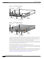
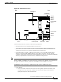
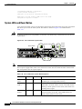
Figure 1-3 shows a Cisco 7120 series router from the back and Figure 1-4 shows a Cisco 7140 series
router. All interface connections and LEDs are located at the back of the router.
The Cisco 7100 series VPN routers have the following components:
•
One fixed WAN port on the Cisco 7120 series—T1, T3, E3, or ATM (T3, E3, or OC-3c/STM1
single-mode intermediate reach).
•
Two fixed WAN ports on the Cisco 7140 series—T3, E3, or ATM (T3, E3 OC-3c/STM1
multimode).
•
Two fixed LAN ports—10BaseT/100BaseTX autosensing Ethernet/Fast Ethernet (full and half
duplex) equipped with an RJ-45 receptacle.
•
One modular port adapter slot—Supports one single-width port adapter.
•
One service module slot—ISM provides encryption services.
•
A Million Instructions Per Second (MIPS) Reduced Instruction Set Computing (RISC) network
processor that supports VPN services at 50 Mbps in Cisco 7120 series routers and 90 Mbps in
Cisco 7140 series routers.
•
One console port—Equipped with an RJ-45 receptacle.
•
One auxiliary port—Equipped with an RJ-45 receptacle.
•
280W AC-input power—Cisco 7120 series routers are equipped with one power supply and
Cisco 7140 series routers are equipped with two power supplies for power load-sharing and
redundancy.
•
Two PC Card slots—Flash Disk or Flash memory cards contain the default Cisco IOS software
image.
•
LEDs—System ready, power, slot 0, slot 1, and LEDs for the fixed LAN and WAN ports.
•
Up to 256 MB of synchronous dynamic random-access memory (SDRAM) system memory with 64
MB of fixed SDRAM packet memory—Three dual in-line memory modules (DIMMs) on the
network processor board.
Cisco 7100 Series VPN Router Installation and Configuration Guide
78-6341-03
1-3
Chapter 1
Overview
Product Description
Figure 1-3
Cisco 7120 Series—Back View
PC Card
slots (covered)
Modular port adapter
ESD receptacle
22066
Service module
SLOT 0
5
SLOT 1
ACT ACT
PWR
RCVR
I
XMTR
EN
0
LNK LNK
1
FE 0 / 0
RCLK FERF RL
FE 0 / 1 0
E3
TX
CONS
RX
AUX
SYS
RDY
AIS OOF LL
2
7120 - T3
Fixed WAN port
Power supply
Fixed LAN ports Console and
auxiliary ports
Figure 1-4
Grounding
receptacles
Cisco 7140 Series—Back View
ESD receptacle
Modular port adapter
18482
Service module
AC OK
DC OK
OTF
SLOT 0
5
SLOT 1
ACT ACT
PWR
I
E3
EN
RX
TX
RX
FE 0 / 0
FE 0 / 1
E3
CEL CAR ALM
EN
RX
0
LNK LNK
0
1
TX
RX
CONS
AUX
SYS
RDY
AC OK
DC OK
OTF
CEL CAR ALM
2
7140 - 2AE3
Fixed WAN port
100-240Vac 50/60Hz
5-2.5A 525W
PC Card
Power supply
slots (covered)
Fixed LAN ports Console and
auxiliary ports
Grounding
receptacles
Cisco 7120 series routers have one power supply with one AC-input power receptacle; Cisco 7140 series
routers have two power supplies with two AC-input power receptacles for power load-sharing and
redundancy. A modular power cable connects each AC-input power supply to the site AC power source.
The router’s main power switch is located next to the AC-input power receptacles.
Cisco 7140 series routers will operate with power connected to either of the two power supplies. The
second AC-input power supply simply enables power load-sharing and redundancy. There is no primary
or secondary power supply for Cisco 7140 series routers.
We recommend powering the router from a 15A receptacle at the power source.
On the side of each chassis are two chassis ground receptacles that provide a chassis ground connection
for a two-hole grounding lug. On the back of the chassis, there is a receptacle for electrostatic discharge
(ESD) equipment. (See Figure 1-3 and Figure 1-4.)
Four internal fans draw cooling air into the chassis (back to front) and across internal components to
maintain an acceptable operating temperature. There are four environmental sensors for monitoring the
cooling air as it leaves the chassis. For more information on environmental monitoring, see the
“Environmental Monitoring and Reporting Functions” section on page 1-39.
Cisco 7100 Series VPN Router Installation and Configuration Guide
1-4
78-6341-03
Chapter 1
Overview
Cisco 7120 Series Overview
Caution
To ensure the proper flow of cooling air across the internal components, make sure a blank port adapter
is installed in an unoccupied port adapter slot. The product number for a blank port adapter is
MAS-7100-PABLANK=.
The modular port adapter slides into the chassis slot and connects directly to the router; there are no
internal cables to connect.
The port adapter, service module, fixed WAN interfaces, and fixed LAN interfaces connect to two
Peripheral Component Interconnect (PCI) buses on the router’s backplane that provide a path to packet
I/O memory and the system processor. For more information, see the “Peripheral Component
Interconnect Buses” section on page 1-33.
Cisco 7100 series VPN routers can be installed on a tabletop or in an equipment rack. Rubber feet for
tabletop installation are included in the accessory kit that shipped with your router. A rack-mount and
cable-management kit is also standard equipment when Cisco 7100 series VPN routers are shipped from
the factory. The kit provides the hardware needed to mount the router in a standard 19- or 23-inch,
four-post or telco-type equipment rack. The kit also provides the hardware necessary to manage the
interface cables attached to the router. The product number for the rack-mount kit is ACS-7100-RMK=.
Instructions for setting the router on a tabletop, installing the router in an equipment rack, and attaching
the cable-management bracket are the same for all Cisco 7100 series VPN models and are explained in
Chapter 3, “Installing a Cisco 7100 VPN Series Router.”
Cisco 7120 Series Overview
Cisco 7120 series routers include the following models:
•
Cisco 7120-4T1—Provides four channel-independent, synchronous serial ports that support
full-duplex operation at T1 (1.544-Mbps) and E1 (2.048-Mbps) speeds.
•
Cisco 7120-T3—Provides one high-speed, synchronous serial port that supports full-duplex
operation at T3 (45-Mbps) speeds.
•
Cisco 7120-E3—Provides one high-speed, synchronous serial port that supports full-duplex
operation at E3 (34-Mbps) speeds.
•
Cisco 7120-AT3—Provides one high-speed, ATM port that supports full-duplex operation at T3
(45-Mbps) speeds.
•
Cisco 7120-AE3—Provides one high-speed, ATM port that supports full-duplex operation at E3
(34-Mbps) speeds.
•
Cisco 7120-SMI3—Provides one ATM port that supports full-duplex operation at OC-3c/STM1
single-mode intermediate reach (155-Mbps) speeds.
Cisco 7120-4T1
The Cisco 7120-4T1 provides four channel-independent, synchronous serial ports that support
full-duplex operation at T1 (1.544-Mbps) and E1 (2.048-Mbps) speeds. The Cisco 7120-4T1 provides
the following features:
•
EIA/TIA-232, EIA/TIA-449, V.35, X.21, and EIA-530 interface types
•
External (data terminal equipment [DTE] mode) or internal (data communications equipment [DCE]
mode) timing signals (except for EIA-530, which only supports external)
Cisco 7100 Series VPN Router Installation and Configuration Guide
78-6341-03
1-5
Chapter 1
Overview
Cisco 7120 Series Overview
•
Loopbacks (except for X.21 DTE)
•
ATM-DXI, Frame Relay, High-Level Data Link Control (HDLC), Point-to-Point Protocol (PPP),
and Switched Multimegabit Data Service (SMDS) encapsulation
•
RFC 1406 (except for the Frac table)
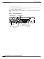
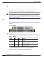
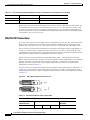
Figure 1-5 shows the back of the Cisco 7120-4T1. Access to the interfaces is located at the back of the
router.
Figure 1-5
Cisco 7120-4T1—Back View
Fast Ethernet 0/0
Modular port adapter
Fast Ethernet 0/1
Service adapter
SLOT 0
SLOT 1
PWR
ACT ACT
0
FE 0 / 0
FE 0 / 1
LNK LNK
0
1
CONS
AUX
SYS
RDY
I
18483
LB
CD
TC
RC
RD
LB
TD
CD
TC
TD
RC
RD
LB
CD
TC
RC
RD
LB
TD
CD
TC
RC
TD
EN
RD
5
2
7120 - 4T1
PC Card
LEDs
Serial 1/2
slots (covered)
Serial 1/1
Serial 1/0
Serial 1/3 Fixed LAN ports
Console and
auxiliary ports
LED
Power supply
T1 WAN ports
Cisco 7100 Series VPN Router Installation and Configuration Guide
1-6
78-6341-03
Chapter 1
Overview
Cisco 7120 Series Overview
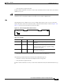
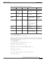
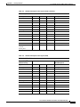
The Cisco 7120-4T1 WAN ports have one enabled (EN) LED and five status LEDs (each of the four
ports has a set of status LEDs). After system initialization, the enabled LED goes on to indicate that all
ports have been enabled for operation. If the initialization fails for any reason, the enabled LED will not
go on. The LEDs are shown in Figure 1-6 and described in Table 1-1.
Figure 1-6
Cisco 7120-4T1 WAN Port LEDs
LB
CD
RC
TC
RD
EN
TD
LEDs
Table 1-1
LB
18485
I
CD
TC
RC
RD
LB
TD
CD
RC
RD
TC
TD
LB
CD
TC
RC
RD
TD
LB
CD
TC
RC
TD
EN
RD
5
Cisco 7120-4T1 LEd Descriptions
LED Label
Color
State
Function
EN
Green
On
Indicates ports are ready.
TD
Green
On
DTE—Transmit data out.
DCE—Transmit data in.
TC
Green
On
DTE—Transmit clock in.
DCE—Transmit clock in (TxCE).
RD
Green
On
DTE—Receive data in.
DCE—Receive data out.
RC
Green
On
DTE—Receive clock in.
DCE—Receive clock out.
LB/CD
Indicates DTR 1, DSR 2, RTS3, CTS4, or DCD 5 is active.
Green
On
Green
Flashing Indicates RTS, CTS, or DCD is sending and receiving data in
half-duplex mode.
Yellow
On
Indicates local loop or internal loop active.
1. DTR = Data Terminal Ready.
2. DSR = Data Set Ready.
3. RTS = Request To Send.
4. CTS = Clear To Send.
5. DCD = Data Carrier Detect.
Cisco 7100 Series VPN Router Installation and Configuration Guide
78-6341-03
1-7
Chapter 1
Overview
Cisco 7120 Series Overview
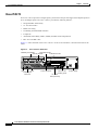
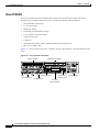
Cisco 7120-T3
The Cisco 7120-T3 provides one high-speed, synchronous serial port that supports full-duplex operation
at T3 (45-Mbps) speeds. The Cisco 7120-T3 provides the following features:
•
Integrated DSU functionality
•
16- and 32-bit CRCs
•
B3ZS line coding
•
Scrambling and bandwidth reduction
•
Loopbacks
•
ATM-DXI, Frame Relay, HDLC, SMDS, and PPP serial encapsulation
•
RFC 1213 and RFC 1407
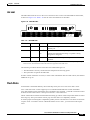
Figure 1-7 shows the back of the Cisco 7120-T3. Access to the interfaces is located at the back of the
router.
Figure 1-7
Cisco 7120-T3—Back View
Fast Ethernet 0/0
Modular port adapter
Fast Ethernet 0/1
Service module
SLOT 0
SLOT 1
PWR
ACT ACT
0
FE 0 / 0
I
RCVR
XMTR
FE
0/1
LNK LNK
0
1
CONS
AUX
SYS
RDY
18486
5
RCLK FERF RL
EN
2
7120 - T3
AIS OOF LL
LED
LEDs
T3 WAN port
serial 1/0
Fixed LAN ports
Console and
auxiliary ports
PC Card
slots (covered)
Power supply
Cisco 7100 Series VPN Router Installation and Configuration Guide
1-8
78-6341-03
Chapter 1
Overview
Cisco 7120 Series Overview
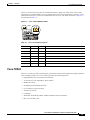
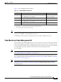
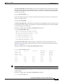
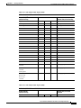
The Cisco 7120-T3 WAN port has one enabled LED and six uplink port status LEDs. After system
initialization, the enabled LED goes on to indicate that the port has been enabled for operation. If the
initialization fails for any reason, the enabled LED will not go on. The LEDs are shown in Figure 1-8
and described in Table 1-2.
Figure 1-8
Cisco 7120-T3 WAN Port LEDs
LEDs
EN
RCLK FERF RL
AIS OOF LL
RCVR
I
XMTR
RCLK FERF RL
EN
AIS OOF LL
Table 1-2
18489
5
Cisco 720-T3 LED Descriptions
LED Label
Color
State
Function
EN
Green
On
Indicates the port is ready.
RCLK
Green
On
Indicates a receive clock has been detected.
FERF
Yellow
On
Indicates the framer detected far-end receive failure.
RL
Yellow
On
Indicates the port is in remote loopback mode.
AIS
Yellow
On
Indicates the framer detected an alarm indication signal.
OOF
Yellow
On
Indicates the framer detected out of frame.
LL
Yellow
On
Indicates the port is in local loopback mode.
Cisco 7120-E3
The Cisco 7120-E3 provides one high-speed, synchronous serial port that supports full-duplex operation
at E3 (34-Mbps) speeds. The Cisco 7120-E3 provides the following features:
•
Integrated data service unit (DSU) functionality
•
16- and 32-bit cyclic redundancy checks (CRCs)
•
HDB3 line coding
•
Scrambling and bandwidth reduction
•
G.751 framing or bypass framing
•
National service bits
•
Loopbacks
•
ATM-DXI, Frame Relay, HDLC, SMDS, and PPP serial encapsulation
•
RFC 1213 and RFC 1407
Cisco 7100 Series VPN Router Installation and Configuration Guide
78-6341-03
1-9
Chapter 1
Overview
Cisco 7120 Series Overview
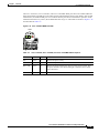
Figure 1-9 shows the back of the Cisco 7120-E3. Access to the interfaces is located at the back of the
router.
Figure 1-9
Cisco 7120-E3—Back View
Fast Ethernet 0/0
Modular port adapter
Fast Ethernet 0/1
Service module
SLOT 0
SLOT 1
PWR
ACT ACT
0
FE 0 / 0
I
RCVR
XMTR
FE
0/1
LNK LNK
0
1
CONS
AUX
SYS
RDY
18488
5
RCLK FERF RL
EN
2
7120 - E3
AIS OOF LL
LED
LEDs
E3 WAN port
serial 1/0
Fixed LAN ports
Console and
auxiliary ports
PC Card
slots (covered)
Power supply
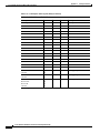
The Cisco 7120-E3 WAN port has one enabled LED and six uplink port status LEDs. After system
initialization, the enabled LED goes on to indicate that the port has been enabled for operation. If the
initialization fails for any reason, the enabled LED will not go on. The LEDs are shown in Figure 1-10
and described in Table 1-3.
Figure 1-10 Cisco 7120-E3 WAN Port LEDs
LEDs
EN
RCLK FERF RL
AIS OOF LL
I
RCVR
XMTR
RCLK FERF RL
EN
AIS OOF LL
Table 1-3
18489
5
Cisco 7120-E3 LED Descriptions
LED Label
Color
State
Function
EN
Green
On
Indicates the port is ready.
RCLK
Green
On
Indicates a receive clock has been detected.
FERF
Yellow
On
Indicates the framer detected far-end receive failure.
RL
Yellow
On
Indicates the port is in remote loopback mode.
AIS
Yellow
On
Indicates the framer detected an alarm indication signal.
OOF
Yellow
On
Indicates the framer detected out of frame.
LL
Yellow
On
Indicates the port is in local loopback mode.
Cisco 7100 Series VPN Router Installation and Configuration Guide
1-10
78-6341-03
Chapter 1
Overview
Cisco 7120 Series Overview
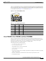
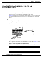
Cisco 7120-AT3, Cisco 7120-AE3, and Cisco 7120-SMI3
The Cisco 7120-AT3 provides one high-speed, ATM port that supports full-duplex operation at T3
(45-Mbps) speeds. The Cisco 7120-AE3 provides one high-speed, ATM port that supports full-duplex
operation at E3 (34-Mbps) speeds. The Cisco 7120-SMI3 provides one ATM port that supports
full-duplex operation at OC-3c/STM1 single-mode intermediate reach (155-Mbps) speeds.
These models provide the following features:
•
Up to 4096 total virtual circuits (open VCs)
•
Up to 1024 simultaneous segmentations and reassemblies (SARs)
•
ATM adaptation layer 5 (AAL5) for data traffic
•
Traffic shaping on a per-VC basis
•
IP-to-ATM class of service (CoS)
•
Non-real time variable bit rate (nrt-VBR), unspecified bit rate (UBR), and available bit rate (ABR)
quality of service (QoS)
•
Operation, Administration, and Maintenance alarm indication signal (OAM AIS) cells
•
LAN emulation (LANE)
•
User-Network Interface (UNI) signaling
•
Integrated Local Management Interface (ILMI)
•
Loopbacks
•
RFC 1483 and RFC 1577
Figure 1-11 shows the back of the Cisco 7120-AT3. Access to the interfaces is located at the back of the
router.
Figure 1-11 Cisco 7120-AT3—Back View
Fast Ethernet 0/0
Modular port adapter
Fast Ethernet 0/1
Service module
SLOT 0
SLOT 1
PWR
ACT ACT
0
5
FE 0 / 0
EN
TX
FE
0/1
CONS
AUX
SYS
RDY
RX
RX
2
CEL CAR ALM
LEDs
ATM T3 WAN port
ATM 1/0
18490
I
DS3
LNK LNK
0
1
7120 - AT3
Fixed LAN ports
Console and
auxiliary ports
PC Card
slots (covered)
Power supply
Cisco 7100 Series VPN Router Installation and Configuration Guide
78-6341-03
1-11
Chapter 1
Overview
Cisco 7120 Series Overview
Figure 1-12 shows the back of the Cisco 7120-AE3. Access to the interfaces is located at the back of the
router.
Figure 1-12 Cisco 7120-AE3—Back View
Fast Ethernet 0/0
Modular port adapter
Fast Ethernet 0/1
Service module
SLOT 0
SLOT 1
PWR
ACT ACT
0
5
FE 0 / 0
EN
TX
FE
0/1
CONS
AUX
SYS
RDY
RX
RX
18491
I
E3
LNK LNK
0
1
2
CEL CAR ALM
7120 - AE3
LEDs
ATM E3 WAN port
ATM 1/0
Fixed LAN ports
Console and
auxiliary ports
PC Card
slots (covered)
Power supply
Figure 1-13 shows the back of the Cisco 7120-SMI3. Access to the interfaces is located at the back of
the router.
Figure 1-13 Cisco 7120-SMI3—Back View
Fast Ethernet 0/0
Modular port adapter
Fast Ethernet 0/1
Service module
SLOT 0
SLOT 1
PWR
ACT ACT
0
5
I
EN
RX
CEL CAR ALM
OC-3-SMI
TX
EN
FE 0 / 1
CONS
AUX
SYS
RDY
RX
2
CEL CAR ALM
LEDs
LEDs
Fixed LAN ports
ATM OC-3 single-mode
WAN port
ATM 1/0
22071
FE 0 / 0
RX
LNK LNK
0
1
7120 - SMI3
Console and
auxiliary ports
Power supply
PC Card
slots (covered)
Cisco 7100 Series VPN Router Installation and Configuration Guide
1-12
78-6341-03
Chapter 1
Overview
Cisco 7120 Series Overview
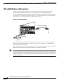
The Cisco 7120-AT3, Cisco 7120-AE3, and Cisco 7120-SMI3 WAN ports have one enabled LED and
three status LEDs. The LEDs are in the same location and labeled the same on each model. After system
initialization, the enabled LED goes on to indicate that the port has been enabled for operation. If the
initialization fails for any reason, the enabled LED will not go on. The LEDs are shown in Figure 1-14
and described in Table 1-4.
Figure 1-14 Cisco 7120-AT3 WAN Port LEDs
LEDs
RX
EN
CEL CAR ALM
I
E3
TX
RX
RX
EN
CEL CAR ALM
Table 1-4
18487
5
Cisco 7120-AT3, Cisco 7120-AE3, and Cisco 7120-SMI3 LED Descriptions
LED Label
Color
State
Function
EN
Green
On
Indicates the port is ready.
RX CEL
Green
On
Indicates the port has received an ATM cell.
RX CAR
Green
On
Indicates the port has detected a carrier on the receiver cable. For a
fiber-optic interface, this means that light is detected, and a valid
frame is detected.
RX ALM
Red
On
Indicates the router detected an alarm condition.
Cisco 7100 Series VPN Router Installation and Configuration Guide
78-6341-03
1-13
Chapter 1
Overview
Cisco 7140 Series Overview
Cisco 7140 Series Overview
Cisco 7140 series routers consist of the following models:
•
Cisco 7140-2T3—Provides two high-speed, synchronous serial ports that support full-duplex
operation at T3 (45-Mbps) speeds.
•
Cisco 7140-2E3— Provides two high-speed, synchronous serial ports that support full-duplex
operation at E3 (34-Mbps) speeds.
•
Cisco 7140-2AT3—Provides two high-speed, ATM ports that support full-duplex operation at T3
(45-Mbps) speeds.
•
Cisco 7140-2AE3—Provides two high-speed, ATM ports that support full-duplex operation at E3
(34-Mbps) speeds.
•
Cisco 7140-2MM3—Provides two ATM ports that support full-duplex operation at OC-3c/STM1
multimode (155-Mbps) speeds.
•
Cisco 7140-8T—Provides eight high-speed, synchronous serial ports that support full-duplex
operation at T1 (1.544-Mbps) and E1 (2.048-Mbps) speeds.
•
Cisco 7140-2FE—Provides two fixed LAN ports—10BaseT/100BaseTX autosensing Ethernet/Fast
Ethernet (full and half duplex) equipped with an RJ-45 receptacle.
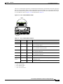
Cisco 7140-2T3
The Cisco 7140-2T3 provides two high-speed, synchronous serial ports that support full-duplex
operation at T3 (45-Mbps) speeds. The Cisco 7140-2T3 provides the following features:
•
Integrated DSU functionality
•
16- and 32-bit CRCs
•
B3ZS line coding
•
Scrambling and bandwidth reduction
•
Loopbacks
•
ATM-DXI, Frame Relay, HDLC, SMDS, and PPP serial encapsulation
•
RFC 1213 and RFC 1407
Cisco 7100 Series VPN Router Installation and Configuration Guide
1-14
78-6341-03
Chapter 1
Overview
Cisco 7140 Series Overview
Figure 1-15 shows the back of the Cisco 7140-2T3. Access to the interfaces is located at the back of the
router.
Figure 1-15 Cisco 7140-2T3—Back View
Fast Ethernet 0/1
Service module
Modular port adapter
Fast Ethernet 0/0
AC OK
DC OK
OTF
SLOT 0
SLOT 1
PWR
ACT ACT
0
5
FE 0 / 0
I
XMTR
RCLK FERF RL RCLK FERF RL
RCVR
0/1
LNK LNK
0
1
CONS
AUX
AC OK
SYS
RDY
DC OK
OTF
XMTR
EN
18492
RCVR
FE
2
7140 - 2T3
AIS OOF LL AIS OOF LL
LED
LEDs
T3 WAN port
serial 1/0
Fixed LAN ports
T3 WAN port
serial 2/0
Console and
auxiliary ports
Power supplies
PC Card
slots (covered)
The Cisco 7140-2T3 WAN ports have one enabled (EN) LED and six uplink port status LEDs (each port
has a set of status LEDs). After system initialization, the enabled LED goes on to indicate that the ports
have been enabled for operation. If the initialization fails for any reason, the enabled LED will not go
on. The LEDs are shown in Figure 1-16 and described in Table 1-5.
Figure 1-16 Cisco 7140-2T3 WAN Port LEDs
LEDs
RCLK FERF RL RCLK FERF RL
EN
AIS OOF LL AIS OOF LL
I
RCVR
XMTR
RCLK FERF RL RCLK FERF RL
RCVR
EN
AIS OOF LL AIS OOF LL
Table 1-5
XMTR
18493
5
Cisco 7140-2T3 LED Descriptions
LED Label Color
State
Function
EN
Green
On
Indicates the port is ready.
RCLK
Green
On
Indicates a receive clock has been detected.
FERF
Yellow
On
Indicates the framer detected far-end receive failure.
RL
Yellow
On
Indicates the port is in remote loopback mode.
AIS
Yellow
On
Indicates the framer detected an alarm indication signal.
OOF
Yellow
On
Indicates the framer detected out of frame.
LL
Yellow
On
Indicates the port is in local loopback mode.
Cisco 7100 Series VPN Router Installation and Configuration Guide
78-6341-03
1-15
Chapter 1
Overview
Cisco 7140 Series Overview
Cisco 7140-2E3
The Cisco 7140-2E3 provides two high-speed, synchronous serial ports that support full-duplex
operation at E3 (34-Mbps) speeds. The Cisco 7140-2E3 provides the following features:
•
Integrated DSU functionality
•
16- and 32-bit CRCs
•
HDB3 line coding
•
Scrambling and bandwidth reduction
•
G.751 framing or bypass framing
•
National service bits
•
Loopbacks
•
ATM-DXI, Frame Relay, HDLC, SMDS, and PPP serial encapsulation
•
RFC 1213 and RFC 1407
Figure 1-17 shows the back of the Cisco 7140-2E3. Access to the interfaces is located at the back of the
router.
Figure 1-17 Cisco 7140-2E3—Back View
Service module
Modular port adapter
AC OK
DC OK
OTF
SLOT 0
SLOT 1
PWR
ACT ACT
0
FE 0 / 0
I
RX
TX
RCLK FERF RL RCLK FERF RL
RX
FE
0/1
LNK LNK
0
1
CONS
AUX
AC OK
SYS
RDY
DC OK
OTF
TX
EN
2
AIS OOF LL AIS OOF LL
7140 - 2E3
LED
LEDs
Fixed LAN ports
Console and
E3 WAN port
auxiliary ports
E3 WAN port
PC Card
slots (covered)
18494
5
Power supplies
Cisco 7100 Series VPN Router Installation and Configuration Guide
1-16
78-6341-03
Chapter 1
Overview
Cisco 7140 Series Overview
The Cisco 7140-2E3 WAN ports have one enabled (EN) LED and six uplink port status LEDs (each port
has a set of status LEDs). After system initialization, the enabled LED goes on to indicate that the ports
have been enabled for operation. If the initialization fails for any reason, the enabled LED will not go
on. The LEDs are shown in Figure 1-18 and described in Table 1-6.
Figure 1-18 Cisco 7140-2E3 WAN Port LEDs
LEDs
RCLK FERF RL RCLK FERF RL
EN
AIS OOF LL AIS OOF LL
I
RCVR
XMTR
RCLK FERF RL RCLK FERF RL
RCVR
XMTR
EN
AIS OOF LL AIS OOF LL
Table 1-6
18493
5
Cisco 7140-2E3 LED Descriptions
LED Label
Color
State
Function
EN
Green
On
Indicates the port is ready.
RCLK
Green
On
Indicates a receive clock has been detected.
FERF
Yellow
On
Indicates the framer detected far-end receive failure.
RL
Yellow
On
Indicates the port is in remote loopback mode.
AIS
Yellow
On
Indicates the framer detected an alarm indication signal.
OOF
Yellow
On
Indicates the framer detected out of frame.
LL
Yellow
On
Indicates the port is in local loopback mode.
Cisco 7140-2AT3, Cisco 7140-2AE3, and Cisco 7140-2MM3
The Cisco 7140-2AT3 provides two high-speed, ATM ports that support full-duplex operation at T3
(45-Mbps) speeds. The Cisco 7140-2AE3 provides two high-speed, ATM ports that support full-duplex
operation at E3 (34-Mbps) speeds. The Cisco 7140-2MM3 provides two ATM ports that support
full-duplex operation at OC-3c/STM1 multimode (155-Mbps) speeds.
These models provides the following features:
•
Up to 4096 total virtual circuits (open VCs)
•
Up to 1024 simultaneous SARs
•
ATM adaptation layer 5 (AAL5) for data traffic
•
Traffic shaping on a per-VC basis
•
IP-to-ATM CoS
•
Non-real time variable bit rate (nrt-VBR), unspecified bit rate (UBR), and available bit rate (ABR)
quality of service (QoS)
•
Operation, Administration, and Maintenance alarm indication signal (OAM AIS) cells
•
LAN emulation (LANE)
Cisco 7100 Series VPN Router Installation and Configuration Guide
78-6341-03
1-17
Chapter 1
Overview
Cisco 7140 Series Overview
•
User-Network Interface (UNI) signaling
•
Integrated Local Management Interface (ILMI)
•
Loopbacks
•
RFC 1483 and RFC 1577
Figure 1-19 shows the back of the Cisco 7140-2AT3. Access to the interfaces is located at the back of
the router.
Figure 1-19 Cisco 7140-2AT3—Back View
Fast Ethernet 0/1
Service module
Modular port adapter
Fast Ethernet 0/0
AC OK
DC OK
OTF
SLOT 0
SLOT 1
PWR
ACT ACT
0
5
I
DS3
EN
TX
FE 0 / 1
RX
RX
LNK LNK
0
1
DS3
AC OK
SYS
RDY
DC OK
OTF
RX
2
CEL CAR ALM
LEDs
ATM T3 WAN port
ATM 1/0
AUX
RX
EN
CEL CAR ALM
TX
CONS
18495
FE 0 / 0
7140 - 2AT3
Fixed LAN ports
Console and
ATM T3 WAN port
auxiliary ports
ATM 2/0
PC Card
slots (covered)
Power supplies
Figure 1-20 shows the back of the Cisco 7140-2AE3. Access to the interfaces is located at the back of
the router.
Figure 1-20 Cisco 7140-2AE3—Back View
Fast Ethernet 0/1
Service module
Modular port adapter
Fast Ethernet 0/0
AC OK
DC OK
OTF
SLOT 0
SLOT 1
PWR
ACT ACT
0
5
I
E3
EN
RX
CEL CAR ALM
TX
FE 0 / 1
RX
E3
EN
TX
CONS
AUX
DC OK
OTF
RX
RX
CEL CAR ALM
AC OK
SYS
RDY
18496
FE 0 / 0
LNK LNK
0
1
2
7140 - 2AE3
Fixed LAN ports
LEDs
Console and
ATM E3 WAN port
ATM E3 WAN port
auxiliary ports
ATM 2/0
ATM 1/0
PC Card
slots (covered)
Power supply
Cisco 7100 Series VPN Router Installation and Configuration Guide
1-18
78-6341-03
Chapter 1
Overview
Cisco 7140 Series Overview
Figure 1-21 shows the back of the Cisco 7140-2MM3. Access to the interfaces is located at the back of
the router.
Figure 1-21 Cisco 7140-2MM3—Back View
Fast Ethernet 0/1
Service module
Modular port adapter
Fast Ethernet 0/0
AC OK
DC OK
OTF
SLOT 0
SLOT 1
PWR
ACT ACT
0
5
I
RX
EN
155 - MM
TX
EN
CEL CAR ALM
FE 0 / 1
LNK LNK
0
1
RX
RX
155 - MM
CONS
AUX
AC OK
SYS
RDY
DC OK
OTF
TX
18497
FE 0 / 0
RX
2
CEL CAR ALM
7140 - 2MM3
LEDs
LEDs
Fixed LAN ports
ATM OC-3
multimode
ATM OC-3 multimode
WAN port
WAN port
ATM 2/0
ATM 1/0
Console and
auxiliary ports
Power supplies
PC Card
slots (covered)
The Cisco 7140-2AT3, Cisco 7140-2AE3, and Cisco 7140-2MM3 WAN ports have one enabled (EN)
LED and three status LEDs (each port has a set of status LEDs). The LEDs are in the same location and
labeled the same on each model. After system initialization, the enabled LED goes on to indicate that
the ports have been enabled for operation. If the initialization fails for any reason, the enabled LED will
not go on. The LEDs are shown in Figure 1-22 and described in Table 1-7.
Figure 1-22 Cisco 7140-2AT3 WAN Port LEDs
LEDs
RX
EN
CEL CAR ALM
I
E3
TX
RX
RX
EN
CEL CAR ALM
Table 1-7
18487
5
Cisco 7140-2AT3, Cisco 7140-2AE3, and Cisco 7140-2MM3 LED Descriptions
LED Label
Color
State
Function
EN
Green
On
Indicates the port is ready.
RX CEL
Green
On
Indicates the port has received an ATM cell.
RX CAR
Green
On
Indicates the port has detected a carrier on the receiver cable.
For a fiber-optic interface, this means that light is detected, and
a valid frame is detected.
RX ALM
Red
On
Indicates the router detected an alarm condition.
Cisco 7100 Series VPN Router Installation and Configuration Guide
78-6341-03
1-19
Chapter 1
Overview
Cisco 7140 Series Overview
Cisco 7140-8T
The Cisco 7140-8T provides eight high-speed, synchronous serial ports that support full-duplex
operation at T1 (1.544-Mbps) and E1 (2.048-Mbps) speeds. The Cisco 7140-8T provides the following
features:
•
EIA/TIA-232, EIA/TIA-449, V.35, X.21, and EIA-530 interface types
•
External (data terminal equipment [DTE] mode) or internal (data communications equipment [DCE]
mode) timing signals (except for EIA-530, which only supports external)
•
Loopbacks (except for X.21 DTE)
•
ATM-DXI, Frame Relay, High-Level Data Link Control (HDLC), Point-to-Point Protocol (PPP),
and Switched Multimegabit Data Service (SMDS) encapsulation
•
RFC 1406 (except for the Frac table)
Figure 1-23 shows the back of the Cisco 7140-8T. Access to the interfaces is located at the back of the
router.
Figure 1-23 Cisco 7140-8T—Back View
Fixed LAN ports
Modular port adapter
Fast Ethernet 0/0
Fast Ethernet 0/1
Service adapter
SLOT 0
FE 0 / 0
PC Card
slots (covered)
SLOT 1
7120 - 4T
FE 0 / 1 ACT ACT
PWR
0
CD
CD
SYS
RDY
LB
TC
AUX
RC
LB
TD
TC
RC
TD
CD
RD
LB
TC
RC
CONS
TD
CD
RD
LB
TC
RC
TD
RD
LB
TC
RC
RD
LB
TC
RC
TD
CD
CD
2
27913
CD
RD
LB
TD
TC
RC
TD
CD
RD
LB
TC
RC
TD
I
RD
EN
LNK LNK
0
1
RD
5
LED
Power supply
Serial 1/2
Serial 1/4
Serial 1/6
Serial 1/1
Serial 1/0
Serial 1/3
Serial 1/5
Serial 1/7 Console and
auxiliary ports
T1 WAN ports
Cisco 7100 Series VPN Router Installation and Configuration Guide
1-20
78-6341-03
Chapter 1
Overview
Cisco 7140 Series Overview
The Cisco 7140-8T WAN ports have one enabled (EN) LED and five status LEDs (each of the eight ports
has a set of status LEDs). After system initialization, the enabled LED goes on to indicate that all ports
have been enabled for operation. If the initialization fails for any reason, the enabled LED will not go
on. The LEDs are shown in Figure 1-24 and described in Table 1-8.
Figure 1-24 Cisco 7140-8T WAN Port LEDs
LB
CD
RC
TC
RD
EN
TD
LEDs
Table 1-8
18485
LB
I
CD
TC
RC
RD
LB
TD
CD
RC
RD
TC
TD
LB
CD
TC
RC
RD
LB
TD
CD
TC
RC
TD
EN
RD
5
Cisco 7140-8T LED Descriptions
LED Label
Color
State
Function
EN
Green
On
Indicates ports are ready.
TD
Green
On
DTE—Transmit data out.
DCE—Transmit data in.
TC
Green
On
DTE—Transmit clock in.
DCE—Transmit clock in (TxCE).
RD
Green
On
DTE—Receive data in.
DCE—Receive data out.
RC
Green
On
DTE—Receive clock in.
DCE—Receive clock out.
Loopback/
Green
On
Indicates DTR 1, DSR 2, RTS3, CTS4, or DCD 5 is active.
Carrier
Detect
Green
Flushing
Indicates RTS, CTS, or DCD is sending and receiving data in
half-duplex mode.
Yellow
On
Indicates local loop or internal loop active.
1. DTR = Data Terminal Ready.
2. DSR = Data Set Ready.
3. RTS = Request To Send.
4. CTS = Clear To Send.
5. DCD = Data Carrier Detect.
Cisco 7100 Series VPN Router Installation and Configuration Guide
78-6341-03
1-21
Chapter 1
Overview
Field-Replaceable Units
Cisco 7140-2FE
The Cisco 7140-2FE provides two fixed LAN ports—10BaseT/100BaseTX autosensing Ethernet/Fast
Ethernet (full and half duplex) equipped with an RJ-45 receptacle.
Figure 1-25 Cisco 7140-2FE—Back View
Fast Ethernet 0/0
Fast Ethernet 0/1
Service module
Modular port adapter
AC OK
DC OK
OTF
SLOT 0
SLOT 1
PWR
ACT ACT
0
5
FE 0 / 0
FE
0/1
LNK LNK
0
1
CONS
AUX
AC OK
SYS
RDY
DC OK
27912
OTF
I
2
7140 - 2FE
Fixed LAN ports
Console and
auxiliary ports
Power supplies
PC Card
slots (covered)
Field-Replaceable Units
Cisco 7100 series VPN routers have the following field-replaceable units (FRUs):
Note
•
Port Adapters, page 1-23
•
Integrated Service Module (ISM)/Integrated Service Adapter (ISA), page 1-23
•
VPN Acceleration Module (VAM), page 1-26
•
Flash Disks, page 1-27
•
SDRAM Memory, page 1-28
•
Rack-Mount and Cable-Management Kit, page 1-29
Replacement instructions for the rack-mount and cable-management kit, SDRAM memory, and Flash
memory PC Cards are contained in the Installing Field-Replaceable Units in Cisco 7100 Series VPN
Routers document.
Replacement instructions for removing and replacing other FRUs are contained in separate documents
found online, and on the Documentation CD-ROM.
Cisco 7100 Series VPN Router Installation and Configuration Guide
1-22
78-6341-03
Chapter 1
Overview
Field-Replaceable Units
Port Adapters
The port adapters installed in Cisco 7100 series VPN routers are of the same type as those installed in
the Cisco 72xx family routers. For information on supported port adapters, refer to the Cisco Product
Catalog or contact your local sales representative. The port adapters provide network interfaces to
connect the router to external networks.
For a complete list of port adapters available to the Cisco 7100 series VPN routers, see the Cisco 7100
Series VPN Router Documentation—DOC-7814391=
http://www.cisco.com/en/US/products/hw/vpndevc/ps333/products_product_index09186a00800fa142.
html
All port adapters available for the Cisco 7100 series connect directly to the router and are locked into
position by a locking tab with two screws (see Figure 1-26). To remove or replace a port adapter, you
must loosen the screws (using a number 2 Phillips screwdriver) and slide the tab down. To lock the port
adapter in place, slide the tab up and tighten the screws.
Note
Detailed port adapter installation information is contained in the installation note for the port adapter.
For example, if you plan to replace a four-port Ethernet port adapter in your Cisco 7100 series VPN
router, refer to the PA-4E Ethernet 10BaseT Port Adapter Installation and Configuration note. The
document is available online and on the Documentation CD-ROM.
Figure 1-26 Port Adapter Locking Tabs—Cisco 7120 Series
Locked
ESD plug
Unlocked
Slot 3
SLOT 0
SLOT 1
PWR
ACT ACT
0
FE 0 / 0
I
E3
EN
FE
0/1
CONS
AUX
SYS
RDY
RX
RX
CEL CAR ALM
Caution
TX
LNK LNK
0
1
2
7120 - AE3
22133
5
To ensure adequate airflow across the router port adapters, a port adapter or a blank port adapter must
be installed in each port adapter slot. The product number for the blank port adapter is
MAS-7100-PABLANK=.
Integrated Service Module (ISM)/Integrated Service Adapter (ISA)
The ISM/ISA is a Layer 3 encryption module that supports IP Security Protocol (IPSec) encryption of
IP datagrams. In addition to enabling the secure use of public switched networks and the Internet through
encryption, the ISM/ISA supports all encryption features supported by the Cisco IOS software. The
hardware-based services provided by the ISM/ISA improve the overall performance of Cisco 7100 series
routers by off-loading data encryption processing from the main system processor.
For more information on ISM or ISA features and for installation and configuration information, refer
to the Integrated Service Adapter and Integrated Service Module Installation and Configuration online.
This document is also available on the Documentation CD-ROM.
Cisco 7100 Series VPN Router Installation and Configuration Guide
78-6341-03
1-23
Chapter 1
Overview
Field-Replaceable Units
Note
The Cisco 7100 series VPN routers do not support an ISM and an ISA in the same chassis.
The boot LED remains lit when the ISA/ISM is configured for MPPE, and it starts to pulsate after
booting when the ISA/ISM is configured for IPSec. The ISA/ISM functions normally whether the boot
LED is pulsating or is solid. See the Integrated Service Adapter and Integrated Service Module
Installation and Configuration for more information on configuring the ISA/ISM.
Caution
To ensure compliance with U.S. export laws and regulations, and to prevent problems later on, refer to
the “Compliance with U.S. Export Laws and Regulations Regarding Encryption” section in the
Regulatory Compliance and Safety Information for the Cisco 7100 Series VPN Routers document for
specific and important information.
ISM
The Integrated Service Module (ISM) is a service module that resides in slot 5 in Cisco 7100 series VPN
routers. The ISM has three LEDs, as shown in Figure 1-27. Table 1-9 lists the colors and functions of
the LEDs.
Figure 1-27 ISM LEDs
RESET
BOOT
ERROR
EN
Note
23774
SM-ISM
The physical orientation of the ISM LEDs is reversed from that of the ISA (see Figure 1-27).
Table 1-9
ISM LEDs
LED Label
Color
State
Function
EN
Green
On
Indicates the ISM is powered up and enabled for
operation.
BOOT
Amber
Pulses1
Indicates the ISM is operating.
On
Indicates the ISM is booting or a packet is being
encrypted or decrypted.
On
Indicates an encryption error has occurred. This
LED is normally off.
ERROR
Amber
1. After successfully booting, the boot LED pulses in a “heartbeat” pattern to indicate that the ISM is operating. As
crypto traffic increases, the nominal level of this LED increases in proportion to the traffic level.
The following conditions must all be met before the enabled LED goes on:
•
The ISM is correctly connected to the backplane and receiving power.
Cisco 7100 Series VPN Router Installation and Configuration Guide
1-24
78-6341-03
Chapter 1
Overview
Field-Replaceable Units
•
The system bus recognizes the ISM.
If either of these conditions is not met, or if the router initialization fails for other reasons, the enabled
LED does not go on.
Caution
To ensure adequate airflow across the router components, an ISM or a blank service module must be
installed in slot 5. The product number for the blank service module is SM-BLANK=.
ISA
The Integrated Service Adapter (ISA) is a service adapter that resides in slot 3 in Cisco 7120 series
routers, and slot 4 in the Cisco 7140 series routers. The ISA has three LEDs, as shown in Figure 1-28.
Table 1-10 lists the colors and functions of the ISA LEDs.
Figure 1-28 ISA Front Panel LEDs (SA-ISA shown)
ENCRYPT/COMP
SA-ISA
LE
AB
EN
17607
R
OT RRO
E
BO
Table 1-10
ISA LEDs
LED Label
Color
State
Function
ENABLE
Green
On
Indicates the ISA is powered up and enabled for
operation.
BOOT
Amber
Pulses1
Indicates the ISA is operating.
On
Indicates the ISA is booting or a packet is being
encrypted or decrypted.
On
Indicates an encryption error has occurred.
ERROR
Amber
This LED is normally off.
1. After successfully booting, the boot LED pulses in a “heartbeat” pattern to indicate that the ISA is operating. As
crypto traffic increases, the nominal level of this LED increases in proportion to the traffic level.
The following conditions must all be met before the enabled LED goes on:
•
The ISA is correctly connected to the backplane and receiving power.
•
The system bus recognizes the ISA.
If either of these conditions is not met, or if the router initialization fails, the enabled LED does not go
on.
Cisco 7100 Series VPN Router Installation and Configuration Guide
78-6341-03
1-25
Chapter 1
Overview
Field-Replaceable Units
VPN Acceleration Module (VAM)
The VPN Acceleration Module (VAM) is a single-width acceleration module. The VAM supports
LAN/WAN media and full Layer 3 routing services. VAMs provide hardware-assisted tunneling and
encryption services for virtual private network (VPN) remote access, site-to-site intranet and extranet
applications, including security, quality of service (QoS), firewall and intrusion detection, and
service-level validation and management. The VAM off-loads IPSec processing from the main processor
to permit resources on the processor engines for other tasks. The VAM provides hardware-accelerated
support for multiple encryption functions.
The VAM is available as a service adapter (SA-VAM), and as a service module (SM-VAM).
SA-VAM
The SA-VAM resides in slot 3 in the Cisco 7120 series routers, and slot 4 in the Cisco 7140 series
routers. The SA-VAM has three LEDs, as shown in Figure 1-29. Table 1-11 lists the colors and functions
of the SA-VAM LEDs.
Figure 1-29 SA-VAM LEDs
ENCRYPT/COMP
SA-VAM
LE
AB
EN
61177
R
OT RRO
BO
E
Table 1-11
SA-VAM LEDs
LED Label
Color
State
ENABLE
Green
On
BOOT
ERROR
Amber
Amber
Pulses
Function
Indicates the VAM is powered up and enabled for operation.
1
Indicates the VAM is operating.
On
Indicates the VAM is booting or a packet is being encrypted or
decrypted.
On
Indicates an encryption error has occurred. This LED is normally
off.
1. After successfully booting, the boot LED pulses in a “heartbeat” pattern to indicate that the VAM is operating. As crypto
traffic increases, the nominal level of this LED increases in proportion to the traffic level.
The following conditions must be met before the enabled LED goes on:
•
The SA-VAM is correctly connected to the backplane and receiving power.
•
The system bus recognizes the SA-VAM.
If either of these conditions is not met, or if the router initialization fails, the enabled LED does not go
on.
Cisco 7100 Series VPN Router Installation and Configuration Guide
1-26
78-6341-03
Chapter 1
Overview
Field-Replaceable Units
SM-VAM
The SM-VAM resides in slot 5 in the Cisco 7100 series VPN routers. The SM-VAM has three LEDs,
as shown in Figure 1-30. Table 1-12 lists the colors and functions of the LEDs.
Figure 1-30 SM-VAM LEDs
60520
E
N
A
B
LE
B
O
O
T
RESET
E
R
R
O
R
SM-VAM
Table 1-12 SM-VAM LEDs
LED Label
Color
State
Function
ERROR
Amber
On
Indicates an encryption error has occurred. This LED is
normally off.
BOOT
Amber
Pulses1
Indicates the SM-VAM is operating.
On
Indicates the SM-VAM is booting or a packet is being
encrypted or decrypted.
On
Indicates the SM-VAM is powered up and enabled for
operation.
ENABLE
Green
1. After successfully booting, the boot LED pulses in a “heartbeat” pattern to indicate that the VAM is operating. As crypto
traffic increases, the nominal level of this LED increases in proportion to the traffic level.
The following conditions must be met before the enabled LED goes on:
•
The SM-VAM is correctly connected to the backplane and receiving power.
•
The system bus recognizes the SM-VAM.
If either of these conditions is not met, or if the router initialization fails for other reasons, the enabled
LED does not go on.
Flash Disks
A Flash Disk is the default memory device that ships with your Cisco 7100 series VPN router.
Cisco 7100 series VPN routers support up to two installed Flash Disks that contain the default
Cisco IOS software image. Flash Disks can be installed in slot 0 and slot 1 of the PC Card slots located
at the back of the router. Slot 0 is the top slot and slot 1 is the bottom slot.
The PC Card must be installed with the back label facing up. The PC Card is keyed and cannot be seated
the wrong way. The ejector button will not pop out if the card is not completely inserted.
To ensure proper electromagnetic compatibility (EMC), the PC Card slot has a cover that is secured with
a captive screw. To install or remove a Flash Disk from slot 0 or slot 1, you must loosen the captive
screw.
Cisco 7100 Series VPN Router Installation and Configuration Guide
78-6341-03
1-27
Chapter 1
Overview
Field-Replaceable Units
Note
To avoid potential problems when you install spare Flash Disks in the router, we recommend that you
reformat all Flash Disks on a Cisco 7100 series VPN router that is running the Cisco IOS release
recommended for your router during your regularly scheduled service times. The Flash Disk requires the
designation disk0 or disk1 to format it.
See the Using the Flash Disk document for additional information on the Flash Disk.This document is
also available on cisco.com and on the Documentation CD-ROM.
Table 1-13 lists the Flash Disk memory options and their product numbers.
Table 1-13 Flash Disk Memory Options
Memory Size
Product Number1
48 MB
MEM-7100-FLD48M
128 MB
MEM-7100-FLD128M
1. These products are also available as Flash Disk upgrades. To order an upgrade, add an equal sign (=) after the product
number, for example, MEM-7100-FLD48M=.
Note
Flash memory cards that are used in Cisco 7200 series and Cisco 7500 series routers are also supported
on Cisco 7100 series routers. For information on the Flash memory card, refer to the Installing
Field-Replaceable Units in Cisco 7100 Series VPN Routers document, available on cisco.com and on
the Documentation CD-ROM.
SDRAM Memory
Warning
Only trained and qualified personnel should be allowed to install, replace, or service this equipment.
This equipment contains an energy hazard. Disconnect the system before servicing.
SDRAM memory consists of three DIMMs on the network processor card that contain the packet and
system memory. By default, each chassis comes with 64 MB of fixed packet memory and 64 MB of
upgradable system memory. You can have up to 256 MB of SDRAM system memory. (For more
information on the network processor, see the “Network Processor Card” section on page 1-34.)
Note
For information on how to replace the SDRAM memory, refer to the Installing Field-Replaceable Units
in Cisco 7100 Series VPN Routers available online and on the Documentation CD.
Cisco 7100 Series VPN Router Installation and Configuration Guide
1-28
78-6341-03
Chapter 1
Overview
Field-Replaceable Units
Table 1-14 lists the SDRAM product numbers.
Table 1-14 SDRAM DIMM Configurations
Total SDRAM
Memory Configuration
Product Number
1 64-MB DIMM in slot DIMM 1
MEM-7120/40-64S(=)
1 64-MB DIMM in slot DIMM 0 2
MEM-7120/40-64P
1 128-MB DIMM in slot DIMM 1
MEM-7120/40-128S=
192 MB
1 128-MB DIMM in slot DIMM 1 and
1 64-MB DIMM in slot DIMM 2
MEM-7120/40-192P=
256 MB
2 128-MB DIMMs; 1 in each slot (DIMM 1 and DIMM 2) MEM-7120/40-256P=
64 MB
1
128 MB
3
1. This is the default memory configuration for all Cisco 7100 series routers.
2. Slot DIMM 0 is used exclusively for packet memory and is fixed at 64 MB.
3. This memory product will be available in the future.
Note
The amount of memory installed in slot DIMM 1 must be greater than or equal to the amount of memory
installed in slot DIMM 2, and slot DIMM 2 can be zero.
Slot DIMM 0 is used exclusively for packet memory and is fixed at 64 MB in the factory.
Rack-Mount and Cable-Management Kit
The rack-mount and cable-management kit for Cisco 7100 series routers consists of rack-mount brackets
and a cable-management bracket that are designed for mounting your router in 19- or 23-inch, four-post
or telco-type equipment racks. The kit is shipped with each Cisco 7100 series router and is also available
as a single FRU. The product number for the rack-mount and cable-management kit is
ACS-7100-RMK=.
Note
Rubber feet for tabletop installation are included in the accessory kit that shipped with your router. (See
the “Setting the Chassis on a Tabletop” section on page 3-1.)
For detailed instructions about how to install the rack-mount and cable-management brackets on your
Cisco 7100 series router, see the “Rack-Mounting the Chassis” section on page 3-2 and the “Connecting
to the Network” section on page 3-7.
Note
Information on how to install the rack-mount and cable-management brackets is in the Installing
Field-Replaceable Units in Cisco 7100 Series VPN Routers document available online and on the
Documentation CD.
Cisco 7100 Series VPN Router Installation and Configuration Guide
78-6341-03
1-29
Chapter 1
Overview
Functional Overview
Functional Overview
The following sections provide a functional overview of Cisco 7100 series VPN routers to help you
become familiar with the capabilities of the router:
•
Chassis Slot and Logical Interface Numbering, page 1-30
•
Online Insertion and Removal, page 1-33
•
Peripheral Component Interconnect Buses, page 1-33
•
Network Processor Card, page 1-34
•
System LEDs and Reset Button, page 1-38
•
Environmental Monitoring and Reporting Functions, page 1-39
Chassis Slot and Logical Interface Numbering
In Cisco 7100 series VPN routers, the slot number is the location in the chassis where the interface
resides and the port number is the physical port associated with that slot. Cisco 7100 series router slots
are numbered 0 through 5. Interfaces in the Cisco IOS software are identified by a type, slot number,
and port number. The number of physical ports depends on the type of modular port adapter or fixed
interface. For example, in a Cisco 7120-4T1, serial 1/0 indicates port 0 on the fixed serial interface in
slot 1. (See Figure 1-5.)
Slots in the Cisco 7120 series are numbered as follows and are shown in Figure 1-31:
•
Slot 0—Fixed LAN (Ethernet) interface
•
Slot 1—Fixed WAN (serial) interface
•
Slot 2—Not used
•
Slot 3—Modular port adapter
•
Slot 4—Not used
•
Slot 5—Integrated Service Module
Figure 1-31 Port Adapter Slot Numbering—Cisco 7120 Series
Slot 5
Slot 4
Slot 3
SLOT 0
SLOT 1
PWR
ACT ACT
0
FE 0 / 0
E3
I
EN
TX
FE
LNK LNK
1
0/1 0
CONS
AUX
SYS
RDY
RX
RX
2
CEL CAR ALM
7120 - AE3
Slot 1
Slot 0
18498
5
Slot 2
Slots in the Cisco 7140 series are numbered as follows and are shown in Figure 1-32:
•
Slot 0—Fixed LAN (Ethernet) interface
•
Slot 1—Fixed WAN (serial) interface
•
Slot 2—Fixed WAN (serial) interface
Cisco 7100 Series VPN Router Installation and Configuration Guide
1-30
78-6341-03
Chapter 1
Overview
Functional Overview
•
Slot 3—Not used
•
Slot 4—Modular port adapter
•
Slot 5—Integrated Service Module
Figure 1-32 Port Adapter Slot Numbering—Cisco 7140 Series
Slot 5
Slot 3
Slot 4
AC OK
DC OK
OTF
RESET
PWR
ACT ACT
EN
5
0
FE 0 / 0
I
SLOT 1
EN
RX
RX
155 - MM
TX
EN
CEL CAR ALM
FE 0 / 1
LNK LNK
0
1
RX
RX
155 - MM
CONS
AC OK
SYS
RDY
DC OK
OTF
2
CEL CAR ALM
Slot 1
AUX
TX
Slot 0
7140 - 2MM3
18499
SM-ISM
SLOT 0
BOOT
ERROR
Slot 2
Interface Information in the Software
You can identify interfaces by using software commands. To display information about all interfaces,
use the show interfaces command. To display information about a specific interface, use the show
interfaces command with the interface type, slot number, and port number in the format show interfaces
type slot/port.
The following example shows how the show interfaces command, used without arguments, displays
status information (including the slot and port number) for each interface in a Cisco 7100 series VPN
router. In the following example, most of the status information for each interface is omitted:
Router# show interfaces
FastEthernet0/0 is up, line protocol is up
Hardware is DEC21140A, address is 0050.73ff.6300 (bia 0050.73ff.6300)
Internet address is 10.0.0.0/1
MTU 1500 bytes, BW 10000 Kbit, DLY 1000 usec,
(display text omitted)
FastEthernet0/1 is administratively down, line protocol is down
Hardware is DEC21140A, address is 0050.73ff.6301 (bia 0050.73ff.6301)
Internet address is 10.0.0.0/2
MTU 1500 bytes, BW 100000 Kbit, DLY 100 usec,
(display text omitted)
Serial1/0 is administratively down, line protocol is down
Hardware is M2T-T3 pa
MTU 4470 bytes, BW 44210 Kbit, DLY 200 usec,
(display text omitted)
Serial1/1 is administratively down, line protocol is down
Hardware is M2T-T3 pa
MTU 4470 bytes, BW 44210 Kbit, DLY 200 usec,
(display text omitted)
FastEthernet4/0 is administratively down, line protocol is down
Hardware is DEC21140, address is 0050.73ff.6370 (bia 0050.73ff.6370)
MTU 1500 bytes, BW 100000 Kbit, DLY 100 usec,
(display text omitted)
Cisco 7100 Series VPN Router Installation and Configuration Guide
78-6341-03
1-31
Chapter 1
Overview
Functional Overview
You can also use arguments such as the interface type (Ethernet, Token Ring, ATM, and so
forth) and the slot/port number to display information about a specific interface only.
The following example shows the display for the fixed LAN (Fast Ethernet interface) port 0
in slot 0:
Router# show interfaces fastethernet 0/0
FastEthernet0/0 is up, line protocol is up
Hardware is DEC21140A, address is 0050.73ff.6300 (bia 0050.73ff.6300)
Internet address is 10.0.0.0/1
MTU 1500 bytes, BW 10000 Kbit, DLY 1000 usec,
reliablility 255/255, txload 1/255, rxload 1/255
Encapsulation ARPA, loopback not set
Keepalive set (10 sec)
Half-duplex, 10Mb/s, 100BaseTX/FX
ARP type:ARPA, ARP Timeout 04:00:00
Last input 00:00:04, output 00:00:03, output hang never
Last clearing of "show interface" counters never
Queueing strategy:fifo
Output queue 0/40, 0 drops; input queue 0/75, 0 drops
5 minute input rate 2000 bits/sec, 1 packets/sec
5 minute output rate 0 bits/sec, 0 packets/sec
134 packets input, 41451 bytes
Received 134 broadcasts, 0 runts, 0 giants, 0 throttles
0 input errors, 0 CRC, 0 frame, 0 overrun, 0 ignored
0 watchdog, 0 multicast
0 input packets with dribble condition detected
26 packets output, 5281 bytes, 0 underruns
0 output errors, 0 collisions, 0 interface resets
0 babbles, 0 late collision, 0 deferred
0 lost carrier, 0 no carrier
0 output buffer failures, 0 output buffers swapped out
For information on the other commands used to configure the router, refer to the Cisco IOS
configuration guides and command references, which are available on the Documentation CD-ROM or
in print.
MAC Addresses
The Media Access Control (MAC) or hardware address is a standardized data-link layer address that is
required for certain network interface types. These addresses are not used by other devices in the
network; they are specific and unique to each port. The router uses a specific method to assign and
control the MAC addresses of its port adapters.
All LAN interfaces (ports) require unique MAC addresses. Typically, the MAC address of an interface
is stored on a memory component that resides directly on the interface circuitry; however, the online
insertion and removal (OIR) feature requires a different method. (For a description of OIR, see “Online
Insertion and Removal” section on page 1-33.)
The OIR feature allows you to remove a port adapter and replace it with another identically configured
one. If the new port adapter matches the port adapter you removed, the system immediately brings it on
line. To allow OIR, an address allocator with unique MAC addresses is stored in an EEPROM on the
router. Each address is reserved for a specific port and slot in the router regardless of whether a port
adapter resides in that slot. The MAC addresses are assigned to slot 3 in Cisco 7120 series routers and
slot 4 in Cisco 7140 series routers. This address scheme allows you to remove a port adapter and insert
the port adapter into other routers without causing the MAC addresses to move around the network or
be assigned to multiple devices.
Cisco 7100 Series VPN Router Installation and Configuration Guide
1-32
78-6341-03
Chapter 1
Overview
Functional Overview
If the MAC addresses were stored on each port adapter, OIR would not function because you could never
replace one port adapter with an identical one; the MAC addresses would always be different. Also, each
time a port adapter was replaced, other devices on the network would have to update their data structures
with the new address and, if they did not do so quickly enough, could cause the same MAC address to
appear in more than one device at the same time.
Note
Storing the MAC addresses for every slot in one central location means the addresses stay with the
memory device on which they are stored.
Online Insertion and Removal
The modular port adapter installed in Cisco 7100 series VPN routers supports OIR. This function allows
you to install and replace a port adapter while the router is operating; you do not need to notify the
software or shut down the system power. This provides a method that is seamless to end users on the
network, maintains all routing information, and preserves sessions.
The following is a functional description of OIR for background information only; for specific
procedures for installing and replacing a port adapter in a Cisco 7100 series VPN router, see the
configuration note that ships with each port adapter.
Each port adapter has a bus connector that connects it to the router. Each connector has a set of tiered
pins in three lengths that send specific signals to the system as they make contact with the port adapter.
The system assesses the signals it receives and the order in which it receives them to determine if a port
adapter is being removed or inserted into the router. From these signals, the system determines whether
to reinitialize a new interface or shut down a removed interface. For example, when you insert a port
adapter, the longest pins make contact with the port adapter first, and the shortest pins make contact last.
The system recognizes the signals and the sequence in which it receives them.
When you remove or insert a port adapter in a Cisco 7100 series VPN router, the port adapter pins send
signals to notify the system, which then performs as follows:
1.
Rapidly scans the system for configuration changes.
2.
Initializes all newly inserted port adapters, noting any removed interfaces and placing them in the
administratively shutdown state.
3.
Brings all previously configured interfaces on the port adapter back to the state they were in when
they were removed. Any newly inserted interfaces are put in the administratively shutdown state, as
if they were present (but not configured) at boot time. If a similar port adapter type is reinserted into
a slot, its ports are configured and brought on line up to the port count of the original port adapter.
Peripheral Component Interconnect Buses
All interfaces connect to two Peripheral Component Interconnect (PCI) buses on the router that provide
a path to packet I/O memory and the network processor. Interfaces in slots 1, 3, and 5 use PCI bus 0 and
interfaces in slots 0, 2, and 4 use PCI bus 1. For port adapters that are installed in the modular port
adapter slots (slot 3 or slot 4), use the guidelines described in Appendix A, “Modular Port Adapter
Configuration Guidelines,” to ensure sufficient bandwidth.
The maximum recommended bandwidth points on each PCI bus is 600 points. For best performance we
recommend that you avoid using port adapters that exceed the total available bandwidth for your router.
Cisco 7100 Series VPN Router Installation and Configuration Guide
78-6341-03
1-33
Chapter 1
Overview
Functional Overview
Network Processor Card
The network processor card resides inside the chassis and is shown in Figure 1-33. The network
processor card provides the following features:
•
Senses OIR of the port adapters
•
Bridges the PCI buses from the interfaces to packet memory
•
Arbitrates traffic across the PCI buses
•
Generates the clock signals for the interfaces on each PCI bus
The network processor card also performs the following system management functions:
Note
•
Sending and receiving routing protocol updates
•
Managing tables, caches, and buffers
•
Monitoring interface and environmental status
•
Providing Simple Network Management Protocol (SNMP) management and the console or Telnet
interface
•
Accounting and switching of data traffic
•
Booting and reloading images
•
Managing port adapters (recognition and initialization during OIR)
Instructions for removing and replacing memory components on the network processor card, such as the
SDRAM DIMMs, are contained in the Installing Field-Replaceable Units in Cisco 7100 Series VPN
Routers document available online and on the Documentation CD.
Cisco 7100 Series VPN Router Installation and Configuration Guide
1-34
78-6341-03
Chapter 1
Overview
Functional Overview
Figure 1-33 Network Processor Card
Back
Front
Environmental
sensor
Polarization
notch alignment
SDRAM
DIMM 1
SDRAM
DIMM 2
Environmental
sensor
18500
Environmental
sensor
SDRAM
DIMM 0
Environmental
sensor
NVRAM
Polarization
notch alignment
Boot ROM
Flash memory
SIMM
The network processor card consists of the following components:
Note
•
Reduced Instruction Set Computing (RISC) microprocessor
•
Two system controllers—Provide processor access to two separate banks of SDRAM and that
permit devices on both PCI buses to access either SDRAM bank. This means that devices on
different PCI buses can access different SDRAM banks simultaneously.
•
Upgradable memory modules—SDRAM system memory is up to 256 MB. (SDRAM packet
memory is fixed at 64 MB.) SDRAM memory stores packets received or sent from network
interfaces, routing tables, and network accounting applications. There are two independent SDRAM
memory arrays that allow concurrent access by interfaces and the processor.
The network processor card contains two SDRAM slots for user-configurable system and packet
memory, DIMM 1 and DIMM 2. The amount of memory installed in slot DIMM 1 must be greater than
or equal to the amount of memory installed in slot DIMM 2, and slot DIMM 2 can be zero.
Slot DIMM 0 is used exclusively for packet memory and is fixed at 64 MB in the factory.
•
Cache memory
– Cisco 7120 series routers have two levels of cache: a primary cache that is internal to the
microprocessor and a secondary, 2-MB (fixed) external cache that provides additional
high-speed storage for data and instructions.
Cisco 7100 Series VPN Router Installation and Configuration Guide
78-6341-03
1-35
Chapter 1
Overview
Functional Overview
– Cisco 7140 series routers have three levels of cache: a primary and a secondary cache that are
internal to the microprocessor and a tertiary, 2-MB (fixed) external cache that provides
additional high-speed storage for data and instructions.
•
Four environmental sensors—Monitor the cooling air as it leaves the chassis.
•
Boot ROM—Stores sufficient code for booting the Cisco IOS software.
•
Flash memory single in-line memory module (SIMM)—Stores the boot image used to boot the
router.
•
NVRAM—Stores the system configuration and environmental monitoring logs (the NVRAM uses
lithium batteries to maintain its contents when disconnected from power).
•
Console port—Provides access for a local terminal and is equipped with an RJ-45 receptacle.
•
Auxiliary port—Provides access for a modem for remote access and is equipped with an RJ-45
receptacle.
•
Two fixed LAN ports—Provide 10BaseT/100BaseTX autosensing Ethernet/Fast Ethernet (full and
half duplex) and are equipped with an RJ-45 receptacle.
•
Two PC Card slots—Contain Flash Disks or Flash memory cards that provide the default Cisco IOS
software image.
Table 1-15 describes the memory types on the network processor card.
Table 1-15 Network Processor Memory Components
Memory Type
Size
Quantity
Description
Location
SDRAM
memory
64 to 128 MB
2 configurable 1
SDRAM slots
64–128-MB DIMMs
(based on maximum
SDRAM required)
DIMM 1 = U13
DIMM 2 = U14
Boot ROM
512 KB
1
OTP2 ROM for the ROM
monitor program
Socket U21
Cisco 7100 Series VPN Router Installation and Configuration Guide
1-36
78-6341-03
Chapter 1
Overview
Functional Overview
Table 1-15 Network Processor Memory Components (continued)
Memory Type
Size
Quantity
Description
Location
Cisco 7120
32 KB
(instruction), 32
KB (data)
–
Processor’s primary
internal cache
Internal to
processor
Cisco 7140
16 KB
(instruction), 16
KB (data)
–
Processor’s primary
internal cache
Internal to
processor
Secondary
cache3
256 KB
–
Processor’s secondary
unified instruction and
data cache
Internal to
Cisco 7140
processors only
External cache
2 MB (fixed)
–
Secondary external cache
for Cisco 7120 series
processors
–
Primary cache
Tertiary external cache for
Cisco 7140 series
processors
Flash memory
SIMM
8 MB
1
Contains the default boot
helper image
Flash SIMM
socket P2
Flash Disk
48 MB and
128 MB
Up to 2
Contains the default
Cisco IOS image
PC Card slot 0
and slot 1
NVRAM
128 KB
1
Nonvolatile EPROM for
the system configuration
file
U69
1. Slot DIMM 0 (U16) is used exclusively for packet memory and is not user-configurable.
2. OTP = one-time programmable.
3. Cisco 7120 series routers do not have a secondary internal cache.
To identify the processor and software version installed in your Cisco 7100 series VPN router, use the
show version command. The following example using a Cisco 7120 series router shows sample output
from the show version command:
Router# show version
Cisco Internetwork Operating System Software
IOS (tm) EGR Software (c7100-P-M), Released Version 12.0(4)XE
Copyright (c) 1986-1999 by cisco Systems, Inc.
Compiled Mon 07-Jun-99 17:49 by biff
Image text-base:0x600088F8, data-base:0x60A54000
ROM:System Bootstrap, Version 12.0(4)XE, RELEASED SOFTWARE
BOOTFLASH:EGR Software (c7100-BOOT-M), Released Version 12.0(4)XE
Router uptime is 19 minutes
System restarted by reload
System image file is "c7100-p-mz"
cisco 7120-T3 (EGR) processor with 61440K/69632K bytes of memory.
R527x CPU at 225Mhz, Implementation 40, Rev 10.0, 2048KB L2 Cache
Last reset from power-on
X.25 software, Version 3.0.0.
Cisco 7100 Series VPN Router Installation and Configuration Guide
78-6341-03
1-37
Chapter 1
Overview
Functional Overview
3 FastEthernet/IEEE 802.3 interface(s)
1 Serial network interface(s)
125K bytes of non-volatile configuration memory.
4096K bytes of Flash internal SIMM (Sector size 256K).
Configuration register is 0x2000
System LEDs and Reset Button
Cisco 7100 series VPN routers provide LEDs to indicate the status of the router and a CPU reset button
that allows you to reset the entire system. The LEDs are shown in Figure 1-34 and described in
Table 1-16.
Caution
To prevent system errors and problems, use the CPU reset button only at the direction of your service
representative.
Figure 1-34 Cisco 7100 Series System LEDs
ACT ACT
System LEDs
PWR
AC OK
DC OK
Reset button
OTF
Power
supply
LEDs
SYS
RDY
LNK LNK
0
1
AC OK
DC OK
OTF
RESET
PWR
ACT ACT
EN
5
0
FE 0 / 0
I
SLOT 1
EN
RX
RX
155 - MM
TX
EN
CEL CAR ALM
FE 0 / 1
RX
LNK LNK
0
1
RX
155 - MM
CONS
AUX
AC OK
SYS
RDY
DC OK
OTF
TX
2
CEL CAR ALM
7140 - 2MM3
SLOT 0
SLOT 1
22058
SM-ISM
SLOT 0
BOOT
ERROR
Slot 0/1 LEDs
Note
The Cisco 7100 series system LEDs are identical for all models except that Cisco 7120 series routers
have no power supply LEDs, while Cisco 7140 series routers have two identical banks of three LEDs
that correspond to each AC-input receptacle.
Table 1-16 Cisco 7100 Series System LED Descriptions
LED Label
Color
State
Function
ACT 0
ACT 1
Green
On
Indicates 10BaseT/100BaseTX Ethernet ports are
transmitting or receiving packets (activity).
LNK 0
LNK 1
Green
On
Indicates 10BaseT/100BaseTX Ethernet ports have
established a valid link with the network. This LED remains
off during normal operation of the router, unless there is an
incoming carrier signal.
SLOT 0
SLOT 1
Green
On
Indicates which PC Card slot is in use when either slot is
being accessed by the system. These LEDs remain off
during normal operation of the router.
Cisco 7100 Series VPN Router Installation and Configuration Guide
1-38
78-6341-03
Chapter 1
Overview
Functional Overview
Table 1-16 Cisco 7100 Series System LED Descriptions (continued)
LED Label
Color
State
Function
PWR
Green
On
Indicates that the power supply is delivering AC-input
power to the router.
SYS RDY
Green
On
Indicates the system is operational.
AC OK
Green
On
Indicates that AC input is within normal range.
DC OK
Green
On
Indicates that DC output is within normal range.
OTF
Green
On
Indicates that internal temperatures are normal.
Amber
On
Indicates a power supply fan failure.
Environmental Monitoring and Reporting Functions
Environmental monitoring and reporting functions are controlled by the network processor and allow
you to maintain normal system operation by identifying and resolving adverse conditions that might
disrupt operation.
The environmental monitoring functions constantly monitor the internal chassis air temperature and
power supply voltages and currents. The power supply monitors its own voltage and temperature and
shuts itself down if it detects a critical condition within the power supply. The reporting functions
periodically log the values of measured parameters so that you can retrieve them for analysis later, and
the reporting functions display warnings on the console if any of the monitored parameters exceed
defined thresholds.
The front and back of the chassis must remain unobstructed to ensure adequate airflow and prevent
overheating inside the chassis; we recommend at least 3 inches (7.6 cm) of clearance. Temperature
sensors in the router monitor the internal air temperature and send warning messages when the internal
air temperature exceeds the specified threshold.
Environmental Monitoring
The environmental monitoring functions use four sensors to monitor the temperature of the cooling air
as it moves through the chassis.
If the air temperature exceeds a defined threshold, the router displays warning messages on the console
terminal. The system stores the present parameter measurements for both temperature and power voltage
in NVRAM so you can retrieve them later.
In addition, the power supply monitors the internal power supply temperature and voltages. A power
supply is either within tolerance (normal) or out of tolerance (critical). If the internal power supply
temperature or voltage reaches a critical level, the power supply shuts down without any interaction with
the system processor.
The environmental monitoring functions use the following levels of status conditions to monitor the
system:
•
Normal—All monitored parameters are within normal tolerances.
•
Warning—The system has exceeded a specified threshold. The system continues to operate, but
operator action is recommended to bring the system back to a normal state.
•
Critical—An out-of-tolerance temperature or voltage condition exists. The system continues to
operate; however, immediate operator action is required.
Cisco 7100 Series VPN Router Installation and Configuration Guide
78-6341-03
1-39
Chapter 1
Overview
Functional Overview
Note
For more information on troubleshooting an overtemperature condition in your router, see the
“Troubleshooting the Cooling Subsystem” section on page 5-6.
Table 1-17 lists the typical temperature thresholds for each network processor type, and Table 1-18 lists
the power thresholds for the normal, warning, and critical (power supply-monitored) levels.
Table 1-17 Typical Processor-Monitored Temperature Thresholds
Note
Parameter
High Warning
High Critical
Core
120°F (49°C)
129°F (54°C)
Chassis inlet
109°F (43°C)
118°F (48°C)
Chassis outlet 1
114°F (46°C)
123°F (51°C)
Chassis outlet 2
116°F (47°C)
125°F (52°C)
If the system reports temperatures in the critical range, you must manually shut down the router. The
processor cannot shut down the router automatically.
Table 1-18 Typical Power Supply-Monitored Voltage Thresholds
Parameter
Low Critical
Low Warning
High Warning
High Critical
+2.5V
+2.35V
+2.39V
+2.69V
+2.72V
+3.3V
+3.11V
+3.19V
+3.39V
+3.47V
+5.15V
+4.88
+5.00
+5.23
+5.39
+12.3V
+11.53
+11.77
+12.76
+13.05
+12.3V
+11.53
+11.77
+12.76
+13.05
–12.5V
–10.20V
–11.24V
–13.71V
–14.33V
Displaying Environmental Status Reports
Cisco 7100 series VPN routers display warning messages on the console if chassis interface-monitored
parameters exceed a desired threshold. You can also retrieve and display environmental status reports
with the show environment, show environment all, show environment last, and show environment
table commands. Parameters are measured and reporting functions are updated every 60 seconds. A
brief description of each of these commands follows.
Caution
To prevent overheating the chassis, ensure that your system is drawing cool inlet air. Overtemperature
conditions can occur if the system is drawing in the exhaust air of other equipment. Ensure adequate
clearance around the sides of the chassis so that cooling air can flow through the chassis interior
unimpeded and exhaust air exits the chassis and is not drawn into the inlet vent of other device.
Cisco 7100 Series VPN Router Installation and Configuration Guide
1-40
78-6341-03
Chapter 1
Overview
Functional Overview
The show environment command displays the current environmental status of the system. The report
displays parameters that are out of the normal values. No parameters are displayed if the system status
is normal. The example that follows shows the display for a system in which all monitored parameters
are within normal range:
Router# show environment
All measured values are normal
If the environmental status is not normal, the system reports the worst-case status level. Following is a
sample overvoltage warning:
Router# show environment
Warning: +3.3 V measured at +3.41 V
The show environment last command retrieves and displays the NVRAM log, which provides a record
of environmental status readings. Air temperature is measured and displayed, and the voltage supplied
by the power supply is also displayed.
Following is sample output of the show environment last command:
Router# show environment last
chassis corepreviously measured at 34C/93F
chassis inletpreviously measured at 28C/82F
chassis outlet 1previously measured at 31C/87F
chassis outlet 2previously measured at 33C/91F
+2.5 Vpreviously measured at +2.59
+3.3 Vpreviously measured at +3.32
+5.15 Vpreviously measured at +5.13
+12.3 Vpreviously measured at +12.99
+12.3 Vpreviously measured at +12.33
-12.5 Vpreviously measured at -12.43
The show environment table command displays the temperature and voltage thresholds for each
temperature sensor and for each monitored status level, which are related to those thresholds listed in
Table 1-17 and Table 1-18.
Following is sample output of the show environment table command:
Router# show environment table
Sample Point
chassis
chassis
chassis
chassis
+2.5 V
+3.3 V
+5.15 V
+12.3 V
+12.3 V
-12.5 V
Note
LowCritical
LowWarning
core
inlet
outlet 1
outlet 2
+2.35
+3.11
+4.88
+11.53
+11.53
-10.20
+2.39
+3.19
+5.00
+11.77
+11.77
-11.24
HighWarning
HighCritical
49C/120F
43C/109F
46C/114F
47C/116F
54C/129F
48C/118F
51C/123F
52C/125F
+2.69
+3.39
+5.23
+12.76
+12.76
-13.71
+2.72
+3.47
+5.39
+13.05
+13.05
-14.33
Temperature ranges and values are subject to change.
The show environment all command displays an extended report that includes temperature readings and
voltage readings.
Following is sample output of the show environment all command:
Router# show environment all
Cisco 7100 Series VPN Router Installation and Configuration Guide
78-6341-03
1-41
Chapter 1
Overview
Functional Overview
Power Supply:
Power supply is standard power supply. Unit is on.
Temperature readings:
chassis core
measured
chassis inlet
measured
chassis outlet 1 measured
chassis outlet 2 measured
Voltage readings:
+2.5 V measured
+3.3 V measured
+5.15 V measured
+12.3 V measured
+12.3 V measured
-12.5 V measured
at
at
at
at
at
at
at
at
at
at
33C/91F
27C/80F
30C/86F
32C/89F
+2.59 V
+3.32 V
+5.13 V
+12.29 V
+12.33 V
-12.43 V
Envm stats saved 2 time(s) since reload
Fan Failures
When the system power is on, all four fans should be operational. The system continues to operate if a
fan fails; however, if the air temperature exceeds a defined threshold, the router displays warning
messages on the console terminal. (See the “Troubleshooting the Cooling Subsystem” section on
page 5-6.)
For complete descriptions and instructions of the environmental monitor commands, refer to the
Configuration Fundamentals Configuration Guide and Configuration Fundamentals Command
Reference publications, available online and on the Documentation CD.
Cisco 7100 Series VPN Router Installation and Configuration Guide
1-42
78-6341-03
C H A P T E R
2
Preparing for Installation
This chapter describes the tasks you must perform before you begin to install a Cisco 7100 series VPN
router and includes the following sections:
Warning
•
Tools and Parts Required, page 2-1
•
Shipping Container Contents, page 2-2
•
Safety Guidelines, page 2-2
Only trained and qualified personnel should be allowed to install, replace, or service this equipment.
This equipment contains an energy hazard. Disconnect the system before servicing.
Read the installation instructions before you connect the system to its power source.
Tools and Parts Required
Cisco 7100 series routers are fully assembled at the factory; no additional assembly is required prior to
installing the router. The following tools and parts are shipped with Cisco 7100 series routers (unless
noted otherwise) and are required for installation:
•
Electrostatic discharge (ESD)-preventive wrist strap
•
Number 2 Phillips screwdriver (not included with the router)
•
Flat-head screwdriver (not included with the router)
•
Rack-mount and cable-management kit for 19- or 23-inch, four-post or telco-type rack installation
•
Rubber feet for desktop installation
•
One double ground lug and two M3.5 x 8-mm screws for grounding the chassis
Cisco 7100 Series VPN Router Installation and Configuration Guide
78-6341-03
2-1
Chapter 2
Preparing for Installation
Shipping Container Contents
Shipping Container Contents
Ensure that the correct Cisco 7100 series router is in the shipping container. The shipping container
includes the following items:
•
Cisco 7100 series router with appropriate port adapter card installed
•
A rack-mount and cable-management kit that includes the following items:
– Two rack-mount brackets for 19-inch rack installations
– Two rack-mount brackets for 23-inch rack installations
– One cable-management bracket
– Sixteen M3.5 x 8-mm Phillips flathead screws for securing the rack-mount brackets to the
chassis
– Two M3.5 x 7-mm slotted hexhead screws for securing the cable-management bracket to the
chassis
Note
Four 10-32 x 3/8-inch slotted binderhead screws are required to secure the chassis to the rack rails; the
binderhead screws are not included in the rack-mount and cable-management kit.
•
ESD-preventive wrist strap
•
Nylon cable tie
•
Cable tie holder
•
Ground lug kit that includes two M3.5 x 7-mm screws
•
Documentation CD-ROM
•
Documentation
– Cisco 7100 Series VPN Router Documentation flyer
– Cisco 7100 Series VPN Router Regulatory Compliance and Safety Information
– A Cisco IOS release note for the software installed on the router
Keep the shipping container in case you must return the router to the factory.
Safety Guidelines
Any device that uses electricity must be handled carefully; follow these guidelines to ensure general
safety:
Warning
•
Keep the chassis area clear and dust-free during and after installation.
•
Put the removed chassis cover in a safe place.
The safety cover is an integral part of the product. Do not operate the unit without the safety cover
installed. Operating the unit without the cover in place will invalidate the safety approvals and pose
a risk of fire and electrical hazards.
•
Keep tools away from walk areas where you and others could fall over them.
Cisco 7100 Series VPN Router Installation and Configuration Guide
2-2
78-6341-03
Chapter 2
Preparing for Installation
Safety Guidelines
Warning
•
Do not wear loose clothing, jewelry (including rings and chains), or other items that could get caught
in the chassis. Fasten your tie or scarf and roll up your sleeves.
•
Wear safety glasses if you are working under any conditions that might be hazardous to your eyes.
•
Do not perform any action that creates a potential hazard to people or makes the equipment unsafe.
•
The installation of the router should be in compliance with national and local electrical codes. In the
United States, National Fire Protection Association (NFPA) 70, United States National Electrical
Code. In Canada, Canadian Electrical Code, part I, CC22.1. In other countries, International
Electrotechnical Commission (IEC) 364, part 1 through part 7.
•
Never attempt to lift an object that might be too heavy for you to lift by yourself.
•
Always turn all power supplies off (O) and unplug all power cables before opening the chassis.
•
Always unplug the power cable before installing or removing a chassis.
•
The AC-powered routers ship with a three-wire electrical grounding-type plug, which only fits into
a grounding-type power outlet. This is a safety feature. The equipment grounding should be in
accordance with local and national electrical codes.
•
The routers operate safely when used in accordance with their marked electrical ratings and product
usage instructions.
Ultimate disposal of this product should be handled according to all national laws and regulations.
Electrical Equipment Guidelines
Warning
Do not touch the power supply when the power cord is connected. For systems with a power switch,
line voltages are present within the power supply even when the power switch is off and the power
cord is connected. For systems without a power switch, line voltages are present within the power
supply when the power cord is connected.
Warning
Before working on equipment that is connected to power lines, remove jewelry (including rings,
necklaces, and watches). Metal objects will heat up when connected to power and ground and can
cause serious burns or can weld the metal object to the terminals.
Warning
This unit might have more than one power supply connection. All connections need to be removed to
de-energize the unit.
Follow these guidelines when you work on equipment powered by electricity.
•
Locate the emergency power-off switch for the room in which you are working.
Then, if an electrical accident occurs, you can act quickly to turn off the power.
•
Before working on the system, unplug the power cord.
•
Disconnect all power before doing the following:
– Installing or removing a chassis
– Working near power supplies
Cisco 7100 Series VPN Router Installation and Configuration Guide
78-6341-03
2-3
Chapter 2
Preparing for Installation
Safety Guidelines
Warning
This equipment is intended to be grounded. Ensure that the host is connected to earth ground during
normal use.
Warning
When installing the unit, the ground connection must always be made first and disconnected last.
•
Do not work alone if potentially hazardous conditions exist.
•
Never assume that power is disconnected from a circuit. Always check.
•
Look carefully for possible hazards in your work area, such as moist floors, ungrounded power
extension cables, frayed power cords, and missing safety grounds.
•
If an electrical accident occurs, proceed as follows:
– Use caution; do not become a victim yourself.
– Turn off power to the system.
– If possible, send another person to get medical aid. Otherwise, assess the condition of the victim
and then call for help.
– Determine if the person needs rescue breathing or external cardiac compressions; then take
appropriate action.
Warning
This product relies on the building’s installation for short-circuit (overcurrent) protection. Ensure that
a fuse or circuit breaker no larger than 120 VAC, 15A U.S. (240 VAC, 10A international) is used on the
phase conductors (all current-carrying conductors).
In addition, use the guidelines that follow when working with any equipment that is disconnected from
a power source, but still connected to telephone wiring or other network cabling.
Warning
•
Never install telephone wiring during a lightning storm.
•
Never install telephone jacks in wet locations unless the jack is specifically designed for wet
locations.
•
Never touch uninsulated telephone wires or terminals unless the telephone line has been
disconnected at the network interface.
•
Use caution when installing or modifying telephone lines.
To reduce the risk of fire, use only No. 26 AWG or larger telecommunication line cord.
Electrostatic Discharge Prevention
Electrostatic discharge (ESD) can damage equipment and impair electrical circuitry. ESD damage
occurs when electronic components are improperly handled and can result in complete or intermittent
failures. Figure 2-1 illustrates how to attach an electrostatic discharge wrist strap.
Always follow ESD-prevention procedures when you remove and replace components. Ensure that the
chassis is electrically connected to earth ground. Wear an ESD-preventive wrist strap, ensuring that it
makes good skin contact. Connect the grounding clip to an unpainted surface of the chassis frame to
Cisco 7100 Series VPN Router Installation and Configuration Guide
2-4
78-6341-03
Chapter 2
Preparing for Installation
Safety Guidelines
safely ground unwanted ESD voltages. To guard against ESD damage and shocks, the wrist strap and
cord must operate properly. If no wrist strap is available, ground yourself by touching the metal part of
the chassis.
Caution
For safety, periodically check the resistance value of the antistatic strap, which should be between 1 and
10 megohms (Mohm).
Figure 2-1
Attaching an Electrostatic Discharge Wrist Strap
ESD
connection
socket
I
E3
EN
RX
TX
RX
CEL CAR ALM
22067
O
OOO
OOO
OOO
OOO
OOOOOOOOOOOOOOOOO
5
OOOOO
OOOOOO OOOOO
OOOO
OOOO
OOO
O
O
OO
OOO
OOO
OOO
OOOO
OOOOO
OOOO
OOOOOOOOOOO
Chassis Lifting Guidelines
A fully configured Cisco 7100 series router weighs approximately 32 pounds (14.5 kg). The chassis is
not intended to be moved frequently. Before you install the router, ensure that your site is properly
prepared so you can avoid having to move the chassis later to accommodate power sources and network
connections.
Whenever you lift the chassis or any heavy object, follow these guidelines:
Warning
•
Always disconnect all external cables before lifting or moving the chassis.
•
Ensure that your footing is solid, and balance the weight of the object between your feet.
•
Lift the chassis slowly; never move suddenly or twist your body as you lift.
•
Keep your back straight and lift with your legs, not your back. If you must bend down to lift the
chassis, bend at the knees, not at the waist, to reduce the strain on your lower back muscles.
•
Lift the chassis from the bottom; grasp the underside of the chassis exterior with both hands.
To prevent personal injury or damage to the chassis, never attempt to lift or tilt the chassis using the
handles on the port adapters; these types of handles are not designed to support the weight of the unit.
Lift the unit only by grasping the chassis underneath its lower edge.
Cisco 7100 Series VPN Router Installation and Configuration Guide
78-6341-03
2-5
Chapter 2
Preparing for Installation
Safety Guidelines
Site Requirement Guidelines
Warning
This unit is intended for installation in restricted access areas. A restricted access area is where
access can only be gained by service personnel through the use of a special tool, lock and key, or
other means of security, and is controlled by the authority responsible for the location.
The environmental monitoring functionality in the router protects the system and components from
potential damage from overvoltage and overtemperature conditions. To ensure normal operation and
avoid unnecessary maintenance, plan your site configuration and prepare your site before installation.
After installation, make sure the site maintains an ambient temperature of 32°F through 104°F (0°C
through 40°C), and keep the area around the chassis as free from dust as is practical.
Planning a proper location for the router and the layout of your equipment rack or wiring closet is
essential for successful system operation. Equipment placed too close together or inadequately
ventilated can cause system overtemperature conditions. In addition, chassis panels made inaccessible
by poor equipment placement can make system maintenance difficult. Following are precautions that
can help avoid problems during installation and ongoing operation.
Follow these general precautions when planning your equipment locations and connections:
•
Plan for access to both front and rear panels of the chassis.
•
Ensure that the room where the chassis operates has adequate ventilation. Remember that electrical
equipment generates heat. Ambient air temperature may not cool equipment to acceptable operating
temperatures without adequate ventilation.
•
Use the show environment command regularly to check the internal system status. The
environmental monitor continually checks the interior chassis environment; it provides warnings for
high temperature and maximum and minimum voltages and creates reports on any occurrences. If
warning messages are displayed, take immediate action to identify the cause and correct the
problem.
•
We recommend keeping the router off the floor and out of any area that tends to collect dust.
•
Follow ESD prevention procedures to avoid damage to equipment. Damage from static discharge
can cause immediate or intermittent equipment failure.
•
Ensure that port adapters and any blank port adapters are in place and secure. The fans direct cooling
air throughout the chassis interior; a loose component or empty slot can redirect the air flow away
from active components.
Rack-Mounting Guidelines
The rack-mounting hardware included with router is suitable for most 19- or 23-inch equipment racks
and telco-type racks. To easily access the interface cables while the router is installed in a rack, make
certain you have access to the rear of the router.
Before using a particular rack, check for obstructions (such as a power strip) that could impair
rack-mount installation. If a power strip does impair a rear rack-mount installation, remove the power
strip before installing the router in the rack, and then replace it after the chassis is installed. As an
alternative, you can mount the router on an equipment shelf provided that the rack dimensions allow you
to secure the router to the shelf, and the overall configuration permits safe installation and access.
However, we recommend rack-mounting the router. Figure 2-2 shows the Cisco 7100 series router
footprint and outer dimensions.
To use the rack-mounting hardware provided with the router, consider the following guidelines:
Cisco 7100 Series VPN Router Installation and Configuration Guide
2-6
78-6341-03
Chapter 2
Preparing for Installation
Safety Guidelines
•
To mount the router between two posts or rails using the brackets, the inner clearance (the width
between the inner sides of the two posts or rails) must be at least 17 inches (43.18 cm).
•
The height of the chassis is 3.5 inches (8.89 cm).
•
When mounting the router in four-post or telco-type racks, be sure to use all the screws and the
brackets provided to secure the chassis to the rack posts.
•
If you plan to use an equipment shelf, ensure that the shelf is constructed to support the weight and
dimensions of the chassis. Figure 2-2 shows the chassis footprint, which you need if you are
designing a customized shelf. We recommend that you use the rack-mount kit designed for
Cisco 7100 series routers.
When planning your rack installation, consider the following guidelines:
•
Install the router in an open rack whenever possible. If installation in an enclosed rack is
unavoidable, ensure that the rack has adequate ventilation.
An enclosed rack should have louvered sides and a fan to provide cooling air because heat generated
by equipment near the bottom of the rack can be drawn upward into the intake ports of the equipment
above.
Caution
To prevent chassis overheating, never install the router in an enclosed rack or room that is not properly
ventilated or air conditioned.
•
Ensure that the rack is not congested, because each unit generates heat. Maintain a minimum
clearance of 3 inches (7.62 cm) on the back and front of the chassis for the cooling air inlet and
exhaust ports, respectively.
•
Baffles can isolate exhaust air from intake air, which also helps to draw cooling air through the
chassis. The best placement of the baffles depends on the airflow patterns in the rack, which can be
found by experimenting with different configurations.
•
When equipment installed in a rack (particularly in an enclosed rack) fails, try operating the
equipment by itself, if possible. Power off other equipment in the rack to allow the unit under test a
maximum of cooling air and clean power.
•
Allow sufficient clearance around the rack for maintenance. If the rack is mobile, you can push it
back near a wall or cabinet for normal operation and pull it out for maintenance (installing or
removing a port adapter or connecting cables). Otherwise, allow 19 inches (48.3 cm) of clearance
to remove the port adapter.
•
Install the chassis and external devices to which it will connect in a contiguous stack.
Cisco 7100 Series VPN Router Installation and Configuration Guide
78-6341-03
2-7
Chapter 2
Preparing for Installation
Safety Guidelines
Note
22136
Chassis width
17.5 in. (44.45 cm)
Chassis depth including cables
23.25 in. (59 cm)
Cisco 7100 Series Router Footprint and Outer Dimensions
Chassis depth
18.25 in. (46.36 cm)
Figure 2-2
•
Always install heavier equipment in the lower half of a rack to maintain a low center of gravity and
prevent the rack from falling over.
•
If you use telco-type racks, be sure that the rack is bolted to the floor and secured because in these
types of installations only one end of the chassis mounts to the two rack posts with the brackets.
Ensure that the weight of the chassis does not make the rack unstable.
•
Provide an adequate chassis ground (earth) connection for your router chassis.
We strongly recommend that you provide a chassis ground connection. (See the “Attaching a System
Ground Connection” section on page 3-4 for instructions.)
In addition to the preceding guidelines, review the precautions for avoiding overtemperature conditions
in the following section, “Temperature and Humidity Requirements.” To properly install a Cisco 7100
series chassis in a rack, see the instructions in the “Rack-Mounting the Chassis” section on page 3-2.
Cisco 7100 Series VPN Router Installation and Configuration Guide
2-8
78-6341-03
Chapter 2
Preparing for Installation
Safety Guidelines
Temperature and Humidity Requirements
Table 2-1 lists the operating and nonoperating environmental site requirements. The ranges listed are
those within which Cisco 7100 series routers continue to operate; however, a measurement that is
approaching the minimum or maximum of a range indicates a potential problem. You can maintain
normal operation by anticipating and correcting environmental anomalies before they approach a
maximum operating range.
Table 2-1
Specifications for Operating and Nonoperating Environments
Specification
Minimum
Maximum
Temperature, ambient operating
32°F (0°C)
104°F (40°C)
Temperature, ambient nonoperating and
storage
–4°F (–20°C)
149°F (65°C)
Humidity, ambient (noncondensing)
operating
10%
90%
Humidity, ambient (noncondensing)
nonoperating and storage
5%
95%
Altitude, operating and nonoperating
Sea level
10,000 ft.
(3050 m)
Vibration, operating
5–200 Hz, 0.5 g (1 octave/min.)
–
Power Connection Guidelines
Follow these precautions and recommendations when planning power connections to a Cisco 7100 series
router:
•
Check the power at your site before installation and periodically after installation to ensure that you
are receiving clean power. Install a power conditioner if necessary.
•
The AC power supply includes the following features:
– Autoselects either 110V or 220V operation.
– All units include a 6-foot (1.8-meter) electrical power cord. (A label near the power cord
indicates the correct voltage, frequency, current draw, and power dissipation for the unit.)
Warning
This product relies on the building’s installation for short-circuit (overcurrent) protection. Ensure that
a fuse or circuit breaker no larger than 120 VAC, 15A U.S. (240 VAC, 10A international) is used on the
phase conductors (all current-carrying conductors).
•
Note
For Cisco 7140 series routers, we recommend connecting each power supply to a separate AC power
source for maximum redundancy.
Cisco 7140 series routers will operate with power connected to either of the two power supplies. The
second AC-input power supply simply enables power load-sharing and redundancy. There is no primary
or secondary power supply for Cisco 7140 series routers.
•
Install proper grounding to avoid damage from lightning and power surges.
Cisco 7100 Series VPN Router Installation and Configuration Guide
78-6341-03
2-9
Chapter 2
Preparing for Installation
Safety Guidelines
Warning
Never defeat the ground conductor or operate the equipment in the absence of a suitably installed
ground conductor. Contact the appropriate electrical inspection authority or an electrician if you are
uncertain that suitable grounding is available.
The Cisco 7100 series router installation must comply with all applicable codes and is approved for use
with copper conductors only. The ground bond fastening hardware should be of compatible material and
preclude loosening, deterioration, and electrochemical corrosion of hardware and joined material.
Attachment of the chassis ground to a central office or other interior ground system should be made with
a 6-AWG, copper ground conductor at a minimum.
The chassis employs two threaded chassis grounding receptacles, located on the sides near the rear of
the chassis, which are intended to be bonded directly to the central offices or other interior ground
system. The chassis ground requires M3.5 screws, which are included. (For instructions on how to
properly ground the chassis, see the “Attaching a System Ground Connection” section on page 3-4.)
•
Note
The AC-input power supply operates on input voltage and frequency within the ranges of 100 to 240
VRMS and 50/60 Hz without the need for operator adjustments. This power supply also incorporates
an active power factor corrector that minimizes the unwanted generation of line current harmonics
that can cause overload of site electrical distribution systems.
We recommend an uninterruptible power source to protect against power failures at your site. We
recommend powering a Cisco 7100 series router from a 15A receptacle at the power source.
Plant Wiring Guidelines
Following are guidelines for setting up the plant wiring and cabling at your site. When planning the
location of the new system, consider the distance limitations for signaling, EMC, and connector
compatibility, as described in the following sections.
Interference Considerations
When wires are run for any significant distance in an electromagnetic field, interference can occur
between the field and the signals on the wires. This fact has two implications for the construction of plant
wiring:
Note
•
Bad wiring practice can result in radio interference emanating from the plant wiring.
•
Strong electromagnetic interference (EMI), especially when it is caused by lightning or radio
transmitters, can destroy the signal drivers and receivers in the router, and can even create an
electrical hazard by conducting power surges through lines and into equipment. (Review the safety
warnings in the “Electrical Equipment Guidelines” section on page 2-3.)
To predict and remedy strong EMI, you may also need to consult experts in radio frequency interference
(RFI).
If you use twisted-pair cable in your plant wiring with a good distribution of grounding conductors, the
plant wiring is unlikely to emit radio interference. If you exceed the recommended distances, use a
high-quality twisted-pair cable with one ground conductor for each data signal when applicable.
Cisco 7100 Series VPN Router Installation and Configuration Guide
2-10
78-6341-03
Chapter 2
Preparing for Installation
Safety Guidelines
If wires exceed recommended distances, or if wires pass between buildings, give special consideration
to the effect of a lightning strike in your vicinity. The electromagnetic pulse caused by lightning or other
high-energy phenomena can easily couple enough energy into unshielded conductors to destroy
electronic devices. If you have had problems of this sort in the past, you may want to consult experts in
electrical surge suppression and shielding.
Distance Limitations and Interface Specifications
The size of your networks and the distances between connections depend on the type of signal, the signal
speed, and the transmission media (the type of cabling used to transmit the signals). For example,
standard coaxial cable has a greater channel capacity than twisted-pair cabling. The distance and rate
limits in the following descriptions are the IEEE recommended maximum speeds and distances for
signaling; however, you can usually get good results at speeds and distances far greater than these. For
example, the recommended maximum rate for V.35 is 2 Mbps, but it is commonly used at 4 Mbps
without any problems. If you understand the electrical problems that might arise and can compensate for
them, you should get good results with rates and distances greater than those shown here; however, do
so at your own risk.
Note
We recommend that you do not exceed specified transmission rate and distance limits.
When preparing your site for network connections to a Cisco 7100 series router, you must consider a
number of factors related to each type of interface:
Note
•
The type of cabling required for each type (fiber, thick or thin coaxial, foil-twisted pair [FTP], or
unshielded twisted-pair [UTP] cabling)
•
Distance limitations for each signal type
•
The specific cables you need to connect each interface
•
Any additional interface equipment you need, such as transceivers, hubs, switches, modems,
channel service units (CSUs), or data service units (DSUs)
•
Cable pinouts if you plan to build your cables
Detailed port adapter installation information is contained in the installation note for the port adapter.
For example, if you plan to replace a four-port Ethernet port adapter in your Cisco 7100 series router,
refer to the PA-4E Ethernet 10BaseT Port Adapter Installation and Configuration note. The document
is available online and on the Documentation CD-ROM.
Also see Appendix C, “Cable Specifications,” for cabling information.
Before installing a Cisco 7100 series router, have all additional external equipment and cables on hand.
For ordering information, contact a customer service representative.
Cisco 7100 Series VPN Router Installation and Configuration Guide
78-6341-03
2-11
Chapter 2
Preparing for Installation
Safety Guidelines
Ethernet Connections
There are two 10BaseT/100BaseTX Fast Ethernet ports on the rear panel of the router. Both ports use
unshielded twisted-pair (UTP) cable. We recommend Category 5 UTP cable. The maximum segment
distance is 328 feet (100 meters). UTP cables look like the cables used for ordinary telephones; however,
UTP cables meet certain electrical standards that telephone cables do not. Cables are not included.
WAN Connections
Cisco 7100 series routers support a wide range of WAN ports on the rear panel of the router. For more
information on the cables used with the WAN ports, see Appendix C, “Cable Specifications.”
Warning
This equipment must be installed and maintained by service personnel as defined by AS/NZS 3260.
Incorrectly connecting this equipment to a general purpose outlet could be hazardous. The
telecommunications lines must be disconnected 1) before unplugging the main power connector
and/or 2) while the housing is open.
Warning
Incorrect connection of this or connected equipment to the general purpose outlet could result in a
hazardous situation.
Warning
Hazardous network voltages are present in WAN ports regardless of whether power to the unit is OFF
or ON. To avoid electric shock, use caution when working near WAN ports. When detaching cables,
detach the end away from the unit first.
Laser and LED Safety Guidelines
The single-mode transmitter in the ATM port uses a small laser to transmit the light signal to the network
ring. Keep the transmit port covered whenever a cable is not connected to it. Although multimode
transceivers typically use LEDs for transmission, it is good practice to keep open ports covered and
avoid staring into open ports or apertures.
The Cisco 7120-SMI and Cisco 7140-MM3 ATM port contains a Class 1 laser warning label.
Warning
Class 1 laser product.
Warning
Because invisible laser radiation may be emitted from the aperture of the port when no fiber cable is
connected, avoid exposure to laser radiation and do not stare into open apertures.
Cisco 7100 Series VPN Router Installation and Configuration Guide
2-12
78-6341-03
Chapter 2
Preparing for Installation
Safety Guidelines
Console and Auxiliary Port Considerations
Cisco 7100 series routers include an asynchronous serial console and auxiliary port. The console and
auxiliary ports provide access to the access server either locally (with a console terminal) or remotely
(with a modem). This section discusses important cabling information to consider before connecting a
console terminal (an ASCII terminal or PC running terminal emulation software) to the console port or
modem to the auxiliary port.
The main difference between the console and auxiliary ports is that the auxiliary port supports hardware
(Request To Send [RTS])/Clear To Send [CTS]) flow control and the console port does not. Flow control
paces the transmission of data between a sending device and a receiving device. Flow control ensures
that the receiving device can absorb the data sent to it before the sending device sends more.
When the buffers on the receiving device are full, a message is sent to the sending device to suspend
transmission until the data in the buffers has been processed. Because the auxiliary port supports flow
control, it is ideally suited for use with the high-speed transmissions of a modem. Console terminals
transmit at slower speeds than modems; therefore, the console port is ideally suited for use with console
terminals.
For detailed information about installing a console terminal and connecting devices to the auxiliary port,
see the “Connecting the Console Port and Auxiliary Port” section on page 3-16. For cable and port
pinouts, see Appendix C, “Cable Specifications.”
Console Port Connections
Cisco 7100 series routers include an EIA/TIA-232 asynchronous serial console port (RJ-45). Depending
on the cable and the adapter used, this port will appear as a data terminal equipment (DTE) or data
communications equipment (DCE) device at the end of the cable. Your router arrives with cables and
adapters to connect a console terminal (an ASCII terminal or PC running terminal emulation software)
to the console port. To connect an ASCII terminal to the console port, use the RJ-45 rollover cable with
the female RJ-45-to-DB-25 adapter (labeled TERMINAL).
To connect a PC running terminal emulation software to the console port, use the RJ-45 rollover cable
with the female RJ-45-to-DB-9 adapter (labeled TERMINAL). The default parameters for the console
port are 9600 baud, 8 data bits, no parity, and 2 stop bits. The console port does not support hardware
flow control.
Auxiliary Port Connections
Cisco 7100 series routers include an EIA/TIA-232 asynchronous serial auxiliary port (RJ-45) that
supports flow control. Depending on the cable and the adapter used, this port will appear as a DTE or
DCE device at the end of the cable. Your router arrives with a cable and an adapter to connect a modem
to the auxiliary port. To connect a modem to the auxiliary port, use the RJ-45 rollover cable with the
male RJ-45-to-DB-25 adapter (labeled MODEM).
Cisco 7100 Series VPN Router Installation and Configuration Guide
78-6341-03
2-13
Chapter 2
Preparing for Installation
Safety Guidelines
Cisco 7100 Series VPN Router Installation and Configuration Guide
2-14
78-6341-03
C H A P T E R
3
Installing a Cisco 7100 VPN Series Router
This chapter explains how to install a Cisco 7100 series router. Before performing any of the procedures
in this chapter, review Chapter 2, “Preparing for Installation,” to ensure you understand all the tools
required and safety guidelines. This chapter includes the following sections:
Warning
•
Setting the Chassis on a Tabletop, page 3-1
•
Rack-Mounting the Chassis, page 3-2
•
Attaching a System Ground Connection, page 3-4
•
Connecting to the Network, page 3-7
•
Connecting to the Network, page 3-7
•
Connecting the Console Port and Auxiliary Port, page 3-16
•
Connecting the Power, page 3-18
Read the installation instructions before you connect the system to its power source.
Setting the Chassis on a Tabletop
The location of the chassis should be placed to avoid inadequate ventilation; inaccessible panels can
cause malfunctions and shutdowns, and can make maintenance difficult.
Note
For help planning the location of your chassis, see the “Site Requirement Guidelines” section on
page 2-6.
We strongly recommend that you provide a chassis ground connection. See the “Attaching a System
Ground Connection” section on page 3-4 for instructions.
Attach the rubber feet as shown in Figure 3-1. Rubber feet are included in the accessory kit that shipped
with your router.For help planning the location of your chassis, see the “Site Requirement Guidelines”
section on page 2-6.
Cisco 7100 Series VPN Router Installation and Configuration Guide
78-6341-03
3-1
Chapter 3
Installing a Cisco 7100 VPN Series Router
Rack-Mounting the Chassis
Attaching the Rubber Feet
22059
Figure 3-1
Cisco 7100 series router
chassis bottom
This completes the general tabletop or workbench installation.
Rack-Mounting the Chassis
This section describes how to rack-mount the chassis in a standard four-post equipment rack. The router
arrives with 19-inch rack-mount brackets and larger brackets for use with a 23- or 24-inch rack. (See
Figure 3-2.)
Note
For help planning your equipment rack configuration, see the “Rack-Mounting Guidelines” section on
page 2-6.
Cisco 7100 Series VPN Router Installation and Configuration Guide
3-2
78-6341-03
Chapter 3
Installing a Cisco 7100 VPN Series Router
Rack-Mounting the Chassis
Standard Rack-Mount Brackets
H6028
Figure 3-2
Bracket for 19-inch rack
Bracket for 23- or 24-inch rack
Attaching the Brackets
To install the chassis in a rack, attach the brackets in one of the following ways:
Note
•
Front panel forward (see Figure 3-3)
•
Back panel forward (see Figure 3-4)
Although the installations show the 19-inch brackets, the procedure is the same for the 24-inch brackets.
Standard Bracket Installation—Front Panel Forward
22061
Figure 3-3
Cisco 7100 SERIES
Standard Bracket Installation—Back Panel Forward
22062
Figure 3-4
0
2
Cisco 7100 Series VPN Router Installation and Configuration Guide
78-6341-03
3-3
Chapter 3
Installing a Cisco 7100 VPN Series Router
Attaching a System Ground Connection
Installing the Chassis in a Rack
After the brackets are secured to the chassis, you can rack-mount the router. Using the screws that you
provide, attach the chassis to the rack as shown in Figure 3-5. You need two people to install the chassis
in the rack—one person to hold the router and one person to secure it to the rack.
If you rack-mount the router with the back panel forward, you might need to attach the system ground
connection before you rack-mount the router. For instructions on how to connect the system ground, see
the next section, “Attaching a System Ground Connection.”
Attaching the Chassis to the Rack—Back Panel Forward
22064
Figure 3-5
0
2
Note: The second bracket attaches to the other side of the chassis.
The brackets can also be installed with the front panel forward.
Attaching a System Ground Connection
Before you connect power or turn on power to your router, we strongly recommend that you provide an
adequate chassis ground (earth) connection for your router’s chassis. Chassis grounding receptacles are
provided on each router chassis.
You will need the following parts and tools:
•
One grounding lug—Must have two M3.5 screw holes that have a 0.63-inch (16.002-mm) spacing
between them, and a wire receptacle large enough to accept a 6-American Wire Gauge (AWG)
multistrand, copper wire. This grounding lug is provided in the accessory kit.
•
Two slotted hexhead M3.5 x 7-mm thread-forming machine screws. These screws are provided in
the accessory kit.
•
One grounding wire—6-AWG, 0.162-inch (4.115-mm) diameter, with approximately 0.108 inch
(2.743 mm) of insulation, for a total wire diameter of approximately 0.27 inch (6.858 mm). The
wire’s length is dependent on your router location and site environment. This wire is not available
from Cisco Systems; it is available from any commercial cable vendor.
•
Flat-blade screwdriver.
•
Crimping tool large enough to accommodate the diameter of the wire receptacle on your grounding
lug.
•
Wire stripper.
Cisco 7100 Series VPN Router Installation and Configuration Guide
3-4
78-6341-03
Chapter 3
Installing a Cisco 7100 VPN Series Router
Attaching a System Ground Connection
To attach the grounding lug to the chassis grounding receptacles, complete the following steps:
Step 1
Strip one end of the 6-AWG wire approximately 0.75 inch (19.05 mm) using the wire stripper.
Step 2
Insert the 6-AWG wire into the wire receptacle on the grounding lug. (See Figure 3-6.)
Figure 3-6
Attaching the Ground Wire to the Grounding Lug
Chassis
grounding
receptacles
Screws
Grounding lug
27307
Wire
Step 3
Crimp the wire receptacle around the wire using the crimping tool.
Step 4
Insert the two screws through the holes in the grounding lug. (See Figure 3-6.) Ensure that the grounding
lug does not interfere with other router hardware.
Step 5
Locate the chassis grounding receptacles on your router chassis. (See Figure 3-7.)
Cisco 7100 Series VPN Router Installation and Configuration Guide
78-6341-03
3-5
Chapter 3
Installing a Cisco 7100 VPN Series Router
Attaching the Cable-Management Bracket
Figure 3-7
Attaching the Grounding Lug to the Chassis Grounding Receptacles
22065
Chassis grounding receptacles
Screws
Grounding lug
0
2
Grounding wire
Step 6
Tighten the grounding lug screws using the flat-blade screwdriver. Do not overtighten the screws.
Step 7
Connect the opposite end of the grounding wire to the appropriate grounding point at your site to ensure
adequate chassis ground.
This completes the procedure for attaching a ground connection.
Attaching the Cable-Management Bracket
To install the cable-management bracket on the router, complete the following steps:
Step 1
Locate the chassis grounding receptacles on the rear sides of the chassis. Both rear sides of Cisco 7100
series chassis have two grounding receptacles. (See Figure 3-8.)
Step 2
Attach the cable-management bracket to the two grounding receptacles that were not used to ground the
chassis in the “Attaching a System Ground Connection” section on page 3-4.
Step 3
Align the cable-management bracket to the vacant receptacles. Ensure the two flanges on the bracket are
facing away from the chassis.
Step 4
Thread two M3.5 x 7-mm slotted hexhead screws through the bracket and into the chassis.
Step 5
Tighten the screws using a flat-head screwdriver.
Step 6
Secure any interface cables to the bracket flanges, using tie wraps.
Cisco 7100 Series VPN Router Installation and Configuration Guide
3-6
78-6341-03
Chapter 3
Installing a Cisco 7100 VPN Series Router
Connecting to the Network
Figure 3-8
Attaching the Cable-Management Bracket to the Chassis
Chassis grounding receptacles
SLOT 0
5
26715
Screws
SLOT 1
ACT ACT
PWR
I
RCVR
EN
XMTR
RCLK FERF RL
FE 0 / 0
FE 0 / 1
0
LNK
1
CONS
AUX
SYS
RDY
AIS OOF LL
2
7120 - T3
Grounding lug
Grounding wire
Cable-management
bracket
This completes the steps for installing the cable-management bracket on a Cisco 7100 series router.
Carefully lace interface cables through the cable-management bracket as needed.
Connecting to the Network
This section describes how to connect the router to your network. Cables to connect the router to a
network are not provided. Contact customer service for ordering information. (See the “Cisco.com”
section on page xix.) For cable product numbers and port pinouts, see Appendix C, “Cable
Specifications.”
The router arrives with the integrated services module (ISM), VPN Acceleration Module (VAM), and
modular port adapter already installed, unless you order the VAM or modular port adapter as a spare.
See the installation and configuration note for the specific port adapter, and the “Port Adapters” section
on page 1-23 for more information on port adapters. See the Integrated Service Adapter and Integrated
Service Module Installation and Configuration guide and the “Integrated Service Module
(ISM)/Integrated Service Adapter (ISA)” section on page 1-23 for information on the ISM and ISA. See
the VPN Acceleration Module (VAM) Installation and Configuration guide and the “VPN Acceleration
Module (VAM)” section on page 1-26 for information on the VAM.
Warning
Do not work on the system or connect or disconnect cables during periods of lightning activity.
Before opening the chassis, disconnect the telephone-network cables to avoid contact with
telephone-network voltages.
Hazardous network voltages are present in WAN ports regardless of whether power to the unit is OFF
or ON. To avoid electric shock, use caution when working near WAN ports. When detaching cables,
detach the end away from the unit first.
Cisco 7100 Series VPN Router Installation and Configuration Guide
78-6341-03
3-7
Chapter 3
Installing a Cisco 7100 VPN Series Router
Connecting to the Network
Connecting the Fast Ethernet Ports
The 10BaseT/100BaseTX Fast Ethernet ports support IEEE 802.3 and IEEE 802.3u specifications for
10-Mbps and 100-Mbps transmission over unshielded twisted-pair (UTP) cables. These ports also
support autosensing and autonegotiation of the proper transmission mode (half duplex or full duplex)
with an attached device.
Each Fast Ethernet port has an RJ-45 connector that supports standard straight-through and crossover
Category 3 or Category 5 UTP cable. Cisco Systems does not supply Category 3 or Category 5 UTP
RJ-45 cables; these cables are available commercially.
Use Category 3 UTP crossover cables when connecting a 10BaseT port to a hub or use Category 3 UTP
straight-through cables when connecting to an end station.
Use Category 5 UTP crossover cables when connecting 100BaseTX to a hub or use Category 5 UTP
straight-through cables when connecting to an end station.
To connect the Fast Ethernet port to an Ethernet hub, use the following procedure:
Step 1
Attach the appropriate cable directly to the receptacle on the router. (See Figure 3-9.)
Step 2
Attach the network end of the cable to an Ethernet hub or end station.
Connecting the LAN Port to an Ethernet Hub
22068
Figure 3-9
AC OK
DC OK
OTF
SLOT 0
5
SLOT 1
ACT ACT
PWR
I
E3
EN
RX
TX
RX
FE 0 / 1 0
E3
CEL CAR ALM
EN
0
LNK LNK
1
FE 0 / 0
RX
TX
CONS
RX
AUX
SYS
RDY
AC OK
DC OK
OTF
CEL CAR ALM
2
7140 - 2AE3
100-240Vac 50/60Hz
5-2.5A 525W
10BaseT/100BaseTX ports
Fast Ethernet 0/0
(RJ-45)
8
7
6
Cisco 7100 series router
Ethernet hub
5
4
3
2
1
Crossover
Ethernet cable
Note
For more information, see the “Fast Ethernet Port Cables and Pinouts” section on page C-4.
Cisco 7100 Series VPN Router Installation and Configuration Guide
3-8
78-6341-03
Chapter 3
Installing a Cisco 7100 VPN Series Router
Connecting to the Network
Connecting the Cisco 7120-4T1 and Cisco 7140-8T
The four T1 ports on the Cisco 7120-4T1 and eight T1 ports on the Cisco 7140-8T and adapter cables
allow a high density of interface ports, regardless of the size of the connectors typically used with each
electrical interface type. All ports use an identical 60-pin D-shell receptacle that supports all interface
types:
•
EIA/TIA-232
•
V.35
•
EIA/TIA-449
•
X.21
•
EIA-530
Each port requires a serial adapter cable, which provides the interface between the high-density serial
port and the standard connectors that are commonly used for each electrical interface type.
The adapter cable determines the electrical interface type and mode of the port (data terminal equipment
[DTE] or data communications equipment [DCE]) to which it is connected.
At system startup or restart, the network processor polls the interfaces and determines the electrical
interface type of each port (according to the type of cable attached). However, it does not necessarily
repoll an interface when you change the cable. To ensure that the system recognizes the new interface
type, use the shutdown interface command before replacing the cable. After you replace the cable, use
the no shutdown interface command to enable the interface.
To connect a serial cable to the network, use the following procedure:
Step 1
Attach the appropriate serial cable directly to the receptacle on the router and tighten the strain-relief
screws. (See .)
Step 2
Attach the network end of the serial cable to a data service unit (DSU), channel service unit (CSU), DTE,
or other external synchronous serial equipment and tighten the strain-relief screws.
Cisco 7100 Series VPN Router Installation and Configuration Guide
78-6341-03
3-9
Chapter 3
Installing a Cisco 7100 VPN Series Router
Connecting to the Network
Figure 3-10 Connecting the T1 WAN Serial Ports on the Cisco 7120-4T1 or Cisco 7140-8T
5
Strain-relief screws
EN
TD
TC
RD
RC
LB
CD
TD
TC
RD
RC
LB
CD
TD
TC
RD
RC
LB
CD
TD
TC
RD
RC
LB
CD
22070
I
Serial 1/0
To CSU, DSU, or external
synchronous serial equipment
Caution
Note
Serial interface cables must be attached correctly or damage to the cable plug will result. Attempting to
force a cable plug on the 60-pin receptacle can damage the plug. (See Appendix C, “Cable
Specifications,” for additional information.)
For more information, see the “Cisco 7120-4T1 and Cisco 7140-8T Cables and Pinouts” section on
page C-5.
Connecting the Cisco 7120-T3, Cisco 7120-E3, Cisco 7140-2T3, and
Cisco 7140-2E3
Use a 75-ohm coaxial cable to connect your router to a T3 or E3 serial network. Serial cables conform
to EIA/TIA-612 and EIA/TIA-613 specifications. The T3 or E3 serial ports on the router are considered
to be DTE devices.
The Cisco 7100 T3 and E3 models have the following port configurations:
•
Cisco 7120-T3—One T3 serial port
•
Cisco 7120-E3—One E3 serial port
•
Cisco 7140-2T3—Two T3 serial ports
•
Cisco 7140-2E3—Two E3 serial ports
Each T3 or E3 serial port has two connectors (receive and transmit), where you connect the
Cisco 75-ohm coaxial cable. The 75-ohm coaxial cable (Cisco product number CAB-ATM-DS3/E3) is
available only from Cisco Systems; it is not available from outside commercial cable vendors.
Cisco 7100 Series VPN Router Installation and Configuration Guide
3-10
78-6341-03
Chapter 3
Installing a Cisco 7100 VPN Series Router
Connecting to the Network
The Cisco 75-ohm coaxial cable is available only in 10-foot (3.05-meter) lengths. The typical maximum
distance between stations for T3 and E3 transmissions is 1300 feet (396 meters).
Note
For E3 (75-ohm) connections, you must have ferrite beads on the 75-ohm coaxial cable and
electromagnetic interference (EMI) decoupling clips on the receiver end of the cable (see Figure 3-12)
if compliance with European certification standards for emission control is required
(EN55022/CISPR22 Class B for radiated emission levels).
Note
The T3 and E3 ports support several types of integrated DSUs. For a listing of the interoperability
guidelines, see Appendix C, “Cable Specifications.”
To connect the T3 or E3 port to the network, use the following procedure:
Step 1
Attach the appropriate coaxial cable directly to the receptacle on the router. (See Figure 3-11 and
Figure 3-12.)
Step 2
Attach the network end of the cable to the external synchronous serial equipment.
Figure 3-11 Connecting the T3 WAN Serial Ports on the Cisco 7140-2T3
5
RCVR
EN
XMTR
RCLK FERF RL RCLK FERF
RL
RCVR
XMTR
22072
I
AIS OOF LL AIS OOF LL
Serial 1/0
Serial 2/0
To T3 network
equipment
Cisco 7100 Series VPN Router Installation and Configuration Guide
78-6341-03
3-11
Chapter 3
Installing a Cisco 7100 VPN Series Router
Connecting to the Network
Figure 3-12 Connecting the E3 WAN Serial Ports on the Cisco 7120-E3
5
RCVR
EN
XMTR
RCLK FERF RL
AIS OOF LL
22073
I
Serial 1/0
Ferrite bead
To E3 network
equipment
You can test the DTE-to-DCE cable connection by using the loopback command.
Note
For more information, see the “Cisco 7120-T3, Cisco 7120-E3, Cisco 7140-2T3, and Cisco 7140-2E3
Cables” section on page C-18.
Connecting the Cisco 7120-AT3, Cisco 7120-AE3, Cisco 7140-2AT3, and
Cisco 7140-2AE3
Use a 75-ohm coaxial cable to connect your router to an ATM T3 or E3 network. The cables conform to
EIA/TIA-612 and EIA/TIA-613 specifications. The ATM T3 or E3 ports on the router are considered
DTE devices.
The Cisco 7120 series ATM models have the following port configurations:
•
Cisco 7120-AT3—One ATM T3 port
•
Cisco 7120-AE3—One ATM E3 port
•
Cisco 7140-2AT3—Two ATM T3 ports
•
Cisco 7140-2AE3—Two ATM E3 ports
AT3 or AE3 ports consist of two connectors, transmit and receive. The 75-ohm coaxial cable (Cisco
product number CAB-ATM-DS3/E3) is available only from Cisco Systems; it is not available from
outside commercial cable vendors.
The Cisco 75-ohm coaxial cable is available only in 10-foot (3.05-meter) lengths. The typical maximum
distance between stations for T3 and E3 transmissions is 1300 feet (396 meters).
Cisco 7100 Series VPN Router Installation and Configuration Guide
3-12
78-6341-03
Chapter 3
Installing a Cisco 7100 VPN Series Router
Connecting to the Network
Note
To ensure compliance with EMI and European certification standards for emission control
(EN55022/CISPR22 Class B for radiated emission levels), the Tx and Rx cables should be tied together
along their entire length, and ferrite beads should be installed on each cable near the Tx and Rx
connectors.
To connect the ATM T3 or E3 port to the network, use the following procedure:
Step 1
Attach the appropriate coaxial cable directly to the receptacle on the router. (See Figure 3-13.)
Step 2
Attach the network end of the cable to the external synchronous serial equipment.
Figure 3-13 Connecting the ATM T3 WAN Ports on the Cisco 7140-2AT3
5
E3
EN
RX
TX
RX
22127
I
CEL CAR ALM
Serial 1/0
To ATM T3 network
equipment
Cisco 7100 Series VPN Router Installation and Configuration Guide
78-6341-03
3-13
Chapter 3
Installing a Cisco 7100 VPN Series Router
Connecting to the Network
Figure 3-14 Connecting the ATM E3 WAN Ports on the Cisco 7140-2AE3
5
DS3
EN
RX
TX
RX
23974
I
CEL CAR ALM
Serial 1/0
Ferrite bead
To ATM E3 network
equipment
Note
For more information, see the “Cisco 7120-AT3, Cisco 7140-2AT3, Cisco 7120-AE3,
Cisco 7140-2AE3, Cisco 7120-SMI3, and Cisco 7140-2MM3 Cables” section on page C-19.
Connecting the Cisco 7120-SMI3 and Cisco 7140-2MM3
The SMI3 (OC-3c/STM-1 single-mode intermediate reach) and MM3 (OC-3c/STM-1 multimode)
interfaces provide an interface to ATM switching fabrics for transmitting and receiving data at rates of
up to 155 Mbps bidirectionally. The MM3 and SMI3 interfaces connect to the SONET/SDH, 155-Mbps
multimode or single-mode optical fiber.
For SONET/SDH multimode and SONET/SDH single-mode connections, use one duplex SC connector
or two simplex SC connectors. The simplex and duplex SC connectors are shipped with removable dust
covers on each connector. These cables are not available from Cisco.
For information on SONET specifications for fiber-optic transmissions, understanding power budget,
and assistance with approximating the power margin for multimode and single-mode transmissions, see
Appendix C, “Cable Specifications.”
Warning
Class 1 laser product.
Because invisible laser radiation may be emitted from the aperture of the port when no fiber cable is
connected, avoid exposure to laser radiation and do not stare into open apertures.
To connect the ATM OC-3c/STM-1 port to the network, use the following procedure:
Cisco 7100 Series VPN Router Installation and Configuration Guide
3-14
78-6341-03
Chapter 3
Installing a Cisco 7100 VPN Series Router
Connecting to the Network
Step 1
Attach the appropriate fiber cable directly to the receptacle on the router. (See Figure 3-15 and
Figure 3-16.)
Step 2
Attach the network end of the cable to an external DSU (an ATM network).
Figure 3-15 Connecting the ATM SMI WAN Ports on the Cisco 7120-SMI3
5
EN
RX OC-3- SMITX
RX
22128
I
CEL CAR ALM
To ATM network
equipment
ATM 1/0
Figure 3-16 Connecting the ATM MM WAN Ports on the Cisco 7140-2MM3
5
EN
RX
RX 155 - MM TX
22129
I
CEL CAR ALM
To ATM network
equipment
Note
ATM 1/0
For more information, see the “Cisco 7120-AT3, Cisco 7140-2AT3, Cisco 7120-AE3,
Cisco 7140-2AE3, Cisco 7120-SMI3, and Cisco 7140-2MM3 Cables” section on page C-19.
Cisco 7100 Series VPN Router Installation and Configuration Guide
78-6341-03
3-15
Chapter 3
Installing a Cisco 7100 VPN Series Router
Connecting the Console Port and Auxiliary Port
Connecting the Console Port and Auxiliary Port
The router arrives with a console and auxiliary cable kit, which contains the cable and adapters you need
to connect a console (an ASCII terminal or PC running terminal emulation software) or modem to the
router. The console and auxiliary cable kit includes:
•
RJ-45-to-RJ-45 rollover cable
•
RJ-45-to-DB-9 female DTE adapter (labeled TERMINAL)
•
RJ-45-to-DB-25 female DTE adapter (labeled TERMINAL)
•
RJ-45-to-DB-25 male DCE adapter (labeled MODEM)
Connecting to the Console Port
Use the console terminal for local administrative access to the router. You can connect a terminal to the
console port only.
To connect the console port to a terminal (an ASCII terminal or a PC running terminal emulation
software), use the following procedure:
Step 1
Attach the appropriate cable (RJ-45 rollover cable and an RJ-45-to-DB-25 or RJ-45-to-DB-9 adapter)
directly to the receptacle on the router. (See Figure 3-17.) The adapters provided are labeled
TERMINAL. Other types of adapters are not included
Step 2
Attach the other end of the cable to a terminal or PC.
Step 3
Configure the terminal or PC terminal emulation software for 9600 baud, 8 data bits, no parity, 2 stop
bits, and no flow control.
Note
If the emulation software flow control setting is “hardware,” the router does not accept input.
Cisco 7100 Series VPN Router Installation and Configuration Guide
3-16
78-6341-03
Chapter 3
Installing a Cisco 7100 VPN Series Router
Connecting the Console Port and Auxiliary Port
22069
Figure 3-17 Connecting the Console Terminal
AC OK
DC OK
OTF
SLOT 0
5
SLOT 1
ACT ACT
PWR
I
E3
EN
RX
TX
RX
FE 0 / 0
FE 0 / 1
E3
CEL CAR ALM
EN
RX
0
LNK LNK
0
1
TX
CONS
RX
AUX
SYS
RDY
AC OK
DC OK
OTF
CEL CAR ALM
2
7140 - 2AE3
100-240Vac 50/60Hz
5-2.5A 525W
Cisco 7100 series router
Console port
(RJ-45)
PC (laptop)
RJ-45-to-RJ-45
rollover cable
RJ-45-to-DB-9 or
RJ-45-to-DB-25 adapter
(labeled TERMINAL)
Note
For more information, see the “Console and Auxiliary Port Cables and Pinouts” section on page C-1.
Connecting a Modem to the Auxiliary Port
You can use the auxiliary port to connect a terminal or a modem for remote access to the router.
To connect the auxiliary port to a modem, use the following procedure:
Step 1
Attach the RJ-45 rollover cable with an RJ-45-to-DB-25 adapter directly to the auxiliary receptacle on
the router. (See Figure 3-18.) The adapter provided is labeled MODEM.
Step 2
Attach the other end of the cable to the modem.
Step 3
Confirm that the modem and the auxiliary port on the router are configured for the same transmission
speed (38400 baud is typical) and hardware flow control with Data Carrier Detect (DCD) and Data
Terminal Ready (DTR) operations.
Cisco 7100 Series VPN Router Installation and Configuration Guide
78-6341-03
3-17
Chapter 3
Installing a Cisco 7100 VPN Series Router
Connecting the Power
23738
Figure 3-18 Connecting a Modem to the Auxiliary Port
AC OK
DC OK
OTF
SLOT 0
5
SLOT 1
ACT ACT
PWR
E3
I
EN
RX
TX
RX
FE 0 / 1 0
E3
CEL CAR ALM
EN
0
LNK LNK
1
FE 0 / 0
RX
TX
CONS
RX
AUX
SYS
RDY
AC OK
DC OK
OTF
CEL CAR ALM
2
7140 - 2AE3
RJ-45-to-RJ-45
rollover cable
Auxiliary port
(RJ-45)
Modem
RJ-45-to-DB-25 adapter
(labeled MODEM)
This completes the procedure for connecting a modem to the auxiliary port. For more information, see
the “Cable Specifications” section on page C-1.
Connecting the Power
Cisco 7120 series and Cisco 7140 series routers feature four-output switching AC power supplies that
provide power factor correction and regulated outputs. Cisco 7120 series routers have one AC-input
power supply and Cisco 7140 series routers have two AC-input power supplies.
Cisco 7140 series routers will operate with power connected to either of the two power supplies. The
second AC-input power supply simply enables power load-sharing and redundancy. There is no primary
or secondary power supply for Cisco 7140 series routers.
For information on the power supply specifications, see Appendix B, “System Specifications.”
Warning
Do not touch the power supply when the power cord is connected. For systems with a power switch,
line voltages are present within the power supply even when the power switch is off and the power
cord is connected. For systems without a power switch, line voltages are present within the power
supply when the power cord is connected.
The AC power supply has double pole/neutral fusing.
Check the following conditions before you start the router:
•
The port adapter is securely inserted in its slot.
•
All network interface cables are connected.
•
A Flash Disk or Flash memory card is installed in its PC Card slot.
•
The console terminal is connected and powered on.
Cisco 7100 Series VPN Router Installation and Configuration Guide
3-18
78-6341-03
Chapter 3
Installing a Cisco 7100 VPN Series Router
Connecting the Power
To connect the AC power on Cisco 7120 series routers, use the following procedure:
Step 1
Turn the power switch to the off (O) position.
Step 2
Connect one end of the power cord to the power connector on the back of the router. (See Figure 3-19.)
AC
DC
5
22131
Figure 3-19 Connecting the AC Power Cord
OTF
ACT ACT
PWR
I
E3
EN
RX
TX
RX
FE 0 / 0
FE 0 / 1
E3
CEL CAR ALM
EN
RX
0
LNK LNK
0
1
TX
RX
CONS
AUX
SYS
RDY
CEL CAR ALM
2
7140 - 2AE3
Step 3
Warning
100-240Vac 50/60Hz
5-2.5A 525W
Connect the other end of the power cord to the power outlet.
The plug-socket combination must be accessible at all times because it serves as the main
disconnecting device.
To connect the AC power on Cisco 7140 series routers (for power load-sharing and redundancy), use the
following procedure to connect the second power supply.
Cisco 7140 series routers will operate with power connected to either of the two power supplies. The
second AC-input power supply simply enables power load-sharing and redundancy. There is no primary
or secondary power supply for the Cisco 7140 series routers.
Step 1
At the back of the router, check that the power switch is in the off (O) position.
Step 2
Slide the cable-retention clip up, away from the second AC-input receptacle, and plug in the power
cable.
Step 3
Secure the cable in the power supply AC-input receptacle by sliding the cable-retention clip down until
it fits around the connector. The cable-retention clip provides strain relief for the AC power cable. (See
Figure 3-20.)
Note
For additional AC power cable strain relief, secure the cable to the power supply handle by inserting a
nylon cable tie through the hole in the handle and around the cable.
Step 4
Plug the AC power supply cable for the second power supply into the AC
power source.
Cisco 7100 Series VPN Router Installation and Configuration Guide
78-6341-03
3-19
Chapter 3
Installing a Cisco 7100 VPN Series Router
Connecting the Power
22135
Figure 3-20 Connecting a Second AC Power Cord
AC OK
DC OK
OTF
SLOT 0
5
SLOT 1
ACT ACT
PWR
I
E3
EN
RX
TX
RX
FE 0 / 1 0
E3
CEL CAR ALM
EN
0
LNK LNK
1
FE 0 / 0
RX
TX
RX
CONS
AUX
SYS
RDY
AC OK
DC OK
OTF
CEL CAR ALM
2
7140 - 2AE3
AC power cable
Note
100-240Vac 50/60Hz
5-2.5A 525W
Cable-retention clip
For information on system startup and software configuration, see Chapter 4, “Performing a Basic
Startup Configuration.”
Cisco 7100 Series VPN Router Installation and Configuration Guide
3-20
78-6341-03
C H A P T E R
4
Performing a Basic Startup Configuration
This chapter describes how to start the system and perform a basic configuration for your Cisco 7100
series router. The chapter includes the following sections:
•
Checking Conditions Prior to System Startup, page 4-1
•
Starting the System and Observing Initial Conditions, page 4-1
•
Configuring a Router, page 4-3
•
Performing Other Configuration Tasks, page 4-19
•
Viewing the System Configuration, page 4-19
•
Replacing or Recovering a Lost Password, page 4-21
Complex configuration procedures are beyond the scope of this publication. See the “Related
Documentation” section on page xi for additional information.
Checking Conditions Prior to System Startup
Check the following conditions before you start your router:
•
Each port adapter is securely inserted in its slot.
•
All network interface cables are connected.
•
A Flash Disk or Flash memory card is installed in its PC Card slot.
•
The power cable is connected and secured with the cable-retention clip.
•
The console terminal is connected and powered on.
Starting the System and Observing Initial Conditions
After installing the router and connecting cables, start the router as follows:
Step 1
Turn the power switch on the power supply to the on (|) position. The green power (PWR) LED on the
router goes on.
Step 2
Listen for the fans; you should immediately hear them operating.
Step 3
During the boot process, observe the system LEDs. The LEDs on most of the fixed interfaces and port
adapters go on and off in irregular sequence. Some may go on, go out, and go on again for a short time.
Cisco 7100 Series VPN Router Installation and Configuration Guide
78-6341-03
4-1
Chapter 4
Performing a Basic Startup Configuration
Starting the System and Observing Initial Conditions
Note
Step 4
The boot LED remains lit when the ISA/ISM is configured for MPPE, and it starts to pulsate after
booting when the ISA/ISM is configured for IPSec. The ISA/ISM functions normally whether the boot
LED is pulsating or is solid. See the Integrated Service Adapter and Integrated Service Module
Installation and Configuration for more information on configuring the ISA/ISM.
Observe the initialization process. When the system boot is complete (a few seconds), the network
processor begins to initialize the interfaces. During this initialization, the LEDs on each port behave
differently (most flash on and off).
The enabled (EN) LED on each interface goes on when initialization is completed, and the console
screen displays a script and system banner similar to the following:
Restricted Rights Legend
Use, duplication, or disclosure by the Government is
subject to restrictions as set forth in subparagraph
(c) of the Commercial Computer Software - Restricted
Rights clause at FAR sec. 52.227-19 and subparagraph
(c) (1) (ii) of the Rights in Technical Data and Computer
Software clause at DFARS sec. 252.227-7013.
cisco Systems, Inc.
170 West Tasman Drive
San Jose, California 95134-1706
Step 5
When you start up the router for the first time, the system automatically enters the setup command
facility, which determines which interfaces are installed and prompts you for configuration information
for each one. On the console terminal, after the system displays the system banner and hardware
configuration, you will see the following System Configuration Dialog prompt:
--- System Configuration Dialog --Would you like to enter the initial configuration dialog? [yes/no]:
You have the option of proceeding with the setup facility to configure the interfaces, or exiting from
setup and using configuration commands to configure global (system-wide) and interface-specific
parameters. You do not have to configure the interface immediately; however, you cannot enable the
interfaces or connect them to any networks until you have configured them.
•
To continue with setup—Enter yes and proceed to the “Performing a Basic Configuration Using the
Setup Facility” section on page 4-4.
•
To use global configuration mode to enter commands manually—Enter no and proceed to the
“Performing a Basic Configuration Using Global Configuration Mode” section on page 4-7.
Some interface LEDs do not light until you have configured them. Complete the first-time startup
procedures and configuration, and then refer to the LED descriptions in Chapter 1, “Overview,” to check
the status of the interfaces.
For specific port and service adapters specific to the Cisco 7100 series VPN routers, see the Cisco 7100
Series VPN Router Documentation flyer, and refer to the specific configuration and installation guide for
your port adapter for information.
For troubleshooting recommendations and procedures, see Chapter 5, “Troubleshooting the
Installation.”
Cisco 7100 Series VPN Router Installation and Configuration Guide
4-2
78-6341-03
Chapter 4
Performing a Basic Startup Configuration
Configuring a Router
Configuring a Router
You can configure or modify the configuration of the router using one of the procedures described in the
following sections:
•
Performing a Basic Configuration Using AutoInstall, page 4-3
•
Performing a Basic Configuration Using the Setup Facility, page 4-4
•
Performing a Basic Configuration Using Global Configuration Mode, page 4-7
Follow the procedure that best fits the needs of your network configuration.
Note
You need to acquire the correct network addresses from your system administrator or consult your
network plan to determine correct addresses before you can complete the router configuration.
Enter the show version command to display the router model and the release of Cisco IOS software that
is supported on the router. (See the “Viewing the System Configuration” section on page 4-19 for sample
output of the show version command.)
Performing a Basic Configuration Using AutoInstall
The AutoInstall process configures the router automatically after connection to the WAN. A
Transmission Control Protocol/Internet Protocol (TCP/IP) host on your network must be preconfigured
to provide the required configuration files. The TCP/IP host may exist anywhere on the network
provided the following two conditions are met:
1.
The host must be on the remote side of the router’s synchronous serial connection to the WAN.
2.
User Datagram Protocol (UDP) broadcasts to and from the router and the TCP/IP host are enabled.
Do not use AutoInstall unless the required files are available on the TCP/IP host. Refer to the
publications Configuration Fundamentals Configuration Guide and Configuration Fundamentals
Command Reference for information about how AutoInstall works. (See “Related Documentation”
section on page xi for more information.
To configure the router using AutoInstall, complete the following steps:
Step 1
Attach the appropriate synchronous serial cable to an available synchronous serial interface on the
router.
Step 2
Turn the power switch on the power supply to the on (|) position. (This action supplies AC power to the
router.)
The router loads the operating system image from Flash memory. If the remote end of the WAN
connection is connected and properly configured, the AutoInstall process begins.
Step 3
After the AutoInstall process is complete, use the copy running-config startup-config command to
write the configuration data to the router’s nonvolatile random-access memory (NVRAM).
Hostname# copy running-config startup-config
Note
This step saves the configuration settings to NVRAM. If you fail to do this, your configuration will be
lost the next time you reload the router.
Cisco 7100 Series VPN Router Installation and Configuration Guide
78-6341-03
4-3
Chapter 4
Performing a Basic Startup Configuration
Configuring a Router
Performing a Basic Configuration Using the Setup Facility
If you do not plan to use AutoInstall, do not connect the router’s serial (WAN) cable to the network. The
router boots from Flash memory and goes automatically into the setup facility, if the WAN interface is
not connected.
You can run the setup facility any time you are at the privileged-level (enable) prompt (#) by entering
the command setup.
Note
If the router does not have a configuration stored in NVRAM, the router attempts to run AutoInstall at
startup. After the router determines that AutoInstall is not configured, it defaults to the setup facility.
Configure the global parameters and interface parameters, if you have not already done so (see “Using
the EXEC Command Interpreter” section on page 4-8). Global parameters are used for controlling
system-wide settings. Interface parameters are used to create a connection over a LAN or WAN.
Complete the following steps to perform a basic configuration using the setup facility:
Step 1
Ensure that a console terminal is connected to the console port, and then boot the router.
The system boots from Flash memory. The following information appears after about 30 seconds. When
you see this information, you have successfully booted your router:
Restricted Rights Legend
Use, duplication, or disclosure by the Government is
subject to restrictions as set forth in subparagraph
(c) of the Commercial Computer Software - Restricted
Rights clause at FAR sec. 52.227-19 and subparagraph
(c) (1) (ii) of the Rights in Technical Data and Computer
Software clause at DFARS sec. 252.227-7013.
cisco Systems, Inc.
170 West Tasman Drive
San Jose, California 95134-1706
Cisco Internetwork Operating System Software
IOS (tm) EGR Software (c7100-P-M), Released Version 12.0(4)XE
Copyright (c) 1986-1999 by cisco Systems, Inc.
Compiled Mon 07-Jun-99 10:25 by biff
Image text-base:0x600088F8, data-base:0x60A54000
cisco 7140-2T3 (EGR) processor with 61440K/69632K bytes of memory.
R7000 CPU at 262Mhz, Implementation 39, Rev 1.0, 256KB L2, 2048KB L3 Cache
Last reset from power-on
X.25 software, Version 3.0.0.
3 FastEthernet/IEEE 802.3 interface(s)
2 Serial network interface(s)
125K bytes of non-volatile configuration memory.
40960K bytes of ATA PCMCIA card at slot 0 (Sector size 512 bytes).
4096K bytes of Flash internal SIMM (Sector size 256K).
Press RETURN to get started!
Cisco 7100 Series VPN Router Installation and Configuration Guide
4-4
78-6341-03
Chapter 4
Performing a Basic Startup Configuration
Configuring a Router
Note
Step 2
The banner and the installed hardware sections of the configuration script appear only at initial system
startup.
Enter yes or press Return to begin the initial configuration dialog.
--- System Configuration Dialog --Would you like to enter the initial configuration dialog? [yes/no]: yes
At any point you may enter a question mark '?' for help.
Use ctrl-c to abort configuration dialog at any prompt.
Default settings are in square brackets '[]'.
Basic management setup configures only enough connectivity
for management of the system, extended setup will ask you
to configure each interface on the system
First, would you like to see the current interface summary? [yes]:
In the following example, the summary shows a router at first-time startup; that is,
nothing is configured. The type of interfaces varies depending on the type of Cisco 7100
series router you are using and the type of modular port adapter that is installed in the
router.
Any interface listed with OK? value “NO” does not have a valid configuration
Interface
FastEthernet0/0
FastEthernet0/1
ATM1/0
ATM2/0
Step 3
IP-Address
unassigned
unassigned
unassigned
unassigned
OK?
NO
NO
NO
NO
Method
unset
unset
unset
unset
Status
up
up
down
down
Protocol
up
up
down
down
Enter the router host name, enable secret password, enable password, and virtual terminal password.
Configuring global parameters:
Enter host name [Router]: sanjose
The enable secret is a password used to protect access to
privileged EXEC and configuration modes. This password, after
entered, becomes encrypted in the configuration.
Enter enable secret: barney
The enable password is used when you do not specify an
enable secret password, with some older software versions, and
some boot images.
Enter enable password: betty
The virtual terminal password is used to protect
access to the router over a network interface.
Enter virtual terminal password: fred
Step 4
Decide whether you want to configure Simple Network Management Protocol (SNMP).
Enter yes or press Return to accept SNMP management; enter no to refuse it.
Configure System Management? [yes/no]: no
Configure SNMP Network Management? [yes]: no
Cisco 7100 Series VPN Router Installation and Configuration Guide
78-6341-03
4-5
Chapter 4
Performing a Basic Startup Configuration
Configuring a Router
Step 5
Choose which protocols to support on your interfaces. For IP-only installations, accept the default values
for most questions. If you are using IP routing, also select one or two of the following interior routing
protocols, using the setup facility: Interior Gateway Routing Protocol (IGRP) or Routing Information
Protocol (RIP).
To configure IP routing, enter yes (the default) or press Return, and then select an interior routing
protocol.
Configure IP? [yes]: yes
Configure IGRP routing? [yes]: yes
Your IGRP autonomous system number [1]: 15
Configure CLNS? [no]: no
Step 6
Configure the Fast Ethernet LAN port in slot 0, using your own addresses and subnet mask at the setup
prompts.
Configuring interface parameters:
Do you want to configure FastEthernet0/0 interface? [yes]: yes
Use the 100 Base-TX (RJ-45) connector? [yes]: yes
Operate in full-duplex mode? [no]: yes
Configure IP on this interface? [yes]: yes
IP address for this interface: 10.1.1.1
Subnet mask for this interface [255.0.0.0]:
Class A network is 10.0.0.0, 8 subnet bits; mask is /8
Do you want to configure FastEthernet0/1 interface? [yes]: no
Step 7
Configure the ATM port in slot 1. Use your own addresses and subnet mask at the setup prompts.
Do you want to configure ATM1/0 interface? [yes]: yes
Configure IP on this interface? [yes]: yes
IP address for this interface: 10.1.1.2
Subnet mask for this interface [255.0.0.0]:
Class A network is 10.0.0.0, 8 subnet bits; mask is /8
Do you want to configure ATM2/0 interface? [yes]:no
Step 8
Configure the synchronous serial port in slot 4. Use your own addresses and subnet mask at the setup
prompts.
Do you want to configure Serial4/0 interface [yes]:
Configure IP on this interface? [yes]:
IP address for this interface: 10.1.1.3
Number of bits in subnet field [0]:
Class A network is 10.1.1.0, 0 subnet bits; mask is /24
Step 9
Review your configuration to view your changes before they are made permanent. The program also asks
you if you want to use this configuration.
The following configuration command script was created:
hostname sanjose
enable secret 5 $1$gG.I$gc9JUfK2r6pIDL0vo3j191
enable password betty
line vty 0 4
password fred
no snmp-server
!
ip routing
no clns routing
!
interface FastEthernet0/0
ip address 10.1.1.1 255.255.0.0
Cisco 7100 Series VPN Router Installation and Configuration Guide
4-6
78-6341-03
Chapter 4
Performing a Basic Startup Configuration
Configuring a Router
no ip directed-broadcast
duplex auto
speed auto
!
interface ATM1/0
ip address 10.1.1.2 255.255.255.0
ip broadcast-address 3.3.3.255
no ip directed-broadcast
shutdown
duplex auto
speed auto
!
interface Serial4/0
ip address 10.1.1.3
no ip directed-broadcast
shutdown
framing c-bit
cablelength 10
dsu bandwidth 44210
!
router igrp 200
network 10.0.0.0
!
end
Step 10
Save the settings to NVRAM.
[0] Go to the IOS command prompt without saving this config.
[1] Return back to the setup without saving this config.
[2] Save this configuration to nvram and exit.
Enter your selection [2]: 2
Your router is now minimally configured and ready to use. You can use the setup command if you want
to modify the parameters after the initial configuration. To perform more complex configurations, use
the configure command.
Performing a Basic Configuration Using Global Configuration Mode
You will need the following information before beginning the procedures in this section:
•
Host name of the router and any passwords you plan to use
•
Protocols you plan to route on each new interface
•
IP addresses if you plan to configure the interfaces for IP routing
•
Timing source for each new interface and clock speeds for external timing
The configure command requires privileged-level access to the EXEC command interpreter, which
usually requires a password. Contact your system administrator if necessary to obtain EXEC-level
access.
Cisco 7100 Series VPN Router Installation and Configuration Guide
78-6341-03
4-7
Chapter 4
Performing a Basic Startup Configuration
Configuring a Router
Using the EXEC Command Interpreter
You modify the configuration of your router through the software command interpreter called the EXEC
(also called enable mode). You must enter the privileged level of the EXEC command interpreter with
the enable command before you can use the configure command to configure a new interface or change
the existing configuration of an interface. The system prompts you for a password if one has been set.
The system prompt for the privileged level ends with a pound sign (#) instead of an angle bracket (>).
At the console terminal, use the following procedure to enter the privileged level:
Step 1
At the user-level EXEC prompt, enter the enable command. The EXEC prompts you for a
privileged-level password as follows:
Router> enable
Password:
Step 2
Enter the password (the password is case sensitive). For security purposes, the password is not displayed.
When you enter the correct password, the system displays the privileged-level system prompt (#):
Router#
Step 3
Enter the configure terminal command at the enable prompt to enter configuration mode from the
terminal.
Router# configure terminal
Enter configuration commands, one per line. End with CNTL/Z.
Router(config)#
At this point, you can configure the router’s host name, passwords, and other global configurations.
Note
Step 4
To see a list of the configuration commands available to you, enter ? at the prompt or press the Help key
while in configuration mode. For more information, refer to the Configuration Fundamentals
Configuration Guide and the Configuration Fundamentals Command Reference. See “Related
Documentation” section on page xi for more information.
At this point, you can either:
•
Save your configuration—See the “Saving the Running Configuration to NVRAM” section on
page 4-17).
•
Configure the fixed interfaces on the router as follows:
– Configuring the Fast Ethernet Interfaces, page 4-9
– Configuring the T1 and E1 Interfaces, page 4-10
– Configuring the T3 Interfaces, page 4-11
– Configuring the E3 Interfaces, page 4-13
– Configuring the ATM Interfaces, page 4-15
Cisco 7100 Series VPN Router Installation and Configuration Guide
4-8
78-6341-03
Chapter 4
Performing a Basic Startup Configuration
Configuring a Router
Configuring the Fast Ethernet Interfaces
The Cisco 7100 series VPN routers have two 10BaseT/100BaseTX autosensing Ethernet/Fast Ethernet
interfaces equipped with RJ-45 receptacles.
To configure the Fast Ethernet interfaces, use the duplex command and the speed command. To fully
enable autonegotiation on the Fast Ethernet interfaces, use the duplex auto command and the speed
auto command.
The default settings and the commands to change the defaults are listed in Table 4-1.
Table 4-1
Fast Ethernet Interface Defaults
Attribute
Default Value
1
Command
Duplex mode
Autonegotiation
duplex {full | half | auto}
no duplex
Speed
Autonegotiation
speed {10 | 100 | auto}
no speed
1. In Cisco IOS Release 12.0(4)XE, the default value for duplex mode is half duplex and the default value for speed is 100 Mbps.
In Cisco IOS Release 12.0(5)XE or later releases of 12.0 XE, and in Cisco IOS Release 12.0(6)T or later releases of 12.0 T,
the default value for duplex mode and speed is autonegotiation.
If the connected Fast Ethernet port does not support autonegotiation or is not configured for
autonegotiation, then the router uses a method called parallel detection which can determine speed, but
not duplex. In this case the autosensensing Fast Ethernet port on your Cisco 7100 series router will
default to half-duplex mode.
To configure the Fast Ethernet port 0, follow the steps below:
Step 1
At the Router (config)# prompt, enter the interface type slot/port command to enter the interface
configuration mode. In this example, Fast Ethernet port 0 is configured:
Router(config)# interface fastethernet 0/0
Router(config-if)#
You can now enter any changes to the configuration.
Note
Step 2
To see a list of the configuration commands available to you, enter ? at the prompt or press the Help key
while in configuration mode.
Specify the IP address. The following example uses an IP address of 10.1.1.20:
Router(config-if)# ip address 10.1.1.20 255.0.0.0
Step 3
Change a default setting or configure other features on the interface, as needed.
The following example shows you how to change the duplex mode (autonegotiation is the default) and
the speed (autonegotiation is the default):
Router(config-if)# duplex half
Router(config-if)# speed 10
Note
For more information on configuring interfaces, refer to the Cisco IOS Interface Configuration
Guide and the Cisco IOS Interface Command Reference publications. See “Related Documentation”
section on page xi for more information.
Cisco 7100 Series VPN Router Installation and Configuration Guide
78-6341-03
4-9
Chapter 4
Performing a Basic Startup Configuration
Configuring a Router
Step 4
Enable the interface.
Router(config-if)# no shutdown
Step 5
Configure additional interfaces as required.
Step 6
Press Ctrl-Z (hold down the Control key while you press Z) or enter end to exit configuration mode
and return to the EXEC command interpreter.
Step 7
Save the configuration to NVRAM as follows:
Router# copy running-config startup-config
[OK]
(See the “Saving the Running Configuration to NVRAM” section on page 4-17. Also see the “Checking
the Interface Configurations” section on page 4-18 for examples of interface configurations.)
Configuring the T1 and E1 Interfaces
The Cisco 7120-4T1 provides four channel-independent, synchronous serial ports that support
full-duplex operation at T1 (1.544-Mbps) and E1 (2.048-Mbps) speeds. The default settings and the
commands to change the defaults are listed in Table 4-2.
Table 4-2
T1 and E1 Interface Defaults
Attribute
Default Value
Command
Duplex mode
Full duplex
half duplex
Clock rate
Uses the external clock rate
timing signal
Invert clock rate
Not inverted
invert-txc
NRZI encoding
NRZ format
nrzi-encoding
CRC 32
16 bits
crc size (16 or 32 bits)
Perform a basic interface configuration using the procedure below.
Note
Additional configuration commands may be required, depending on your system requirements and the
protocols you plan to route on the interface.
At any time, you can exit the privileged level and return to the user level by entering disable at the
prompt as follows:
Router# disable
Step 1
At the Router (config)# prompt, enter the interface type slot/port command to enter the interface
configuration mode. In this example, the serial port 0 is configured:
Router(config)# interface serial 1/0
Router(config-if)#
Enter any changes to the configuration.
Cisco 7100 Series VPN Router Installation and Configuration Guide
4-10
78-6341-03
Chapter 4
Performing a Basic Startup Configuration
Configuring a Router
Note
Step 2
To see a list of the configuration commands available to you, enter ? at the prompt or press the Help key
while in configuration mode.
Specify the IP address. The following example uses an IP address of 10.1.1.10:
Router(config-if)# ip address 10.1.1.10 255.0.0.0
Step 3
Change the default settings or configure other features on the interface as needed.
The following example sets the external clock rate to 72 kbps:
Router(config-if)# clockrate 72000
Enter the clockrate ? command for a list of valid clock rates. If you enter a nonstandard clock rate (that
is, a rate not displayed by the clockrate ? command), the clock rate is rounded to the nearest value that
the hardware can support. To determine the value that the clock rate was rounded to, use the
show running-configuration command.
Set the external clock rate in bits-per-second if you are configuring a data communications equipment
(DCE) interface or you want to perform a loopback test. Skip this step if you are configuring a data
terminal equipment (DTE) interface; the interface automatically uses the external timing signal.
The T1 and E1 interfaces support both DTE and DCE mode, depending on the mode of the interface
cable attached to the port.
The DCE interface generates its own clock signal (TxC) and sends it to the remote DTE. The remote
DTE device returns the clock signal to the DCE. (See Table 4-2 for a list of commands used to change
the default settings.)
Note
Step 4
For more information on configuring interfaces, refer to the Cisco IOS Interface Configuration
Guide and the Cisco IOS Interface Command Reference publications. See “Related Documentation”
section on page xi for more information.
Enable the interface.
Router(config-if)# no shutdown
Step 5
Press Ctrl-Z (hold down the Control key while you press Z) or enter end to exit configuration mode
and return to the EXEC command interpreter.
Step 6
Save the new configuration to NVRAM as follows:
Router# copy running-config startup-config
[OK]
(See the “Saving the Running Configuration to NVRAM” section on page 4-17. Also see the “Checking
the Interface Configurations” section on page 4-18 for examples of interface configurations.)
Configuring the T3 Interfaces
The Cisco 7120-T3 provides one and the Cisco 7140-2T3 provides two high-speed, synchronous serial
ports that support full-duplex operation at T3 (45-Mbps) speeds. The default settings and the commands
to change the defaults are listed in Table 4-3.
Cisco 7100 Series VPN Router Installation and Configuration Guide
78-6341-03
4-11
Chapter 4
Performing a Basic Startup Configuration
Configuring a Router
Table 4-3
T3 Interface Defaults
Attribute
Default Value
Command
Clock source
Line
clock source
DSU bandwidth
44210
dsu bandwidth kbps (22 to 44210)
DSU mode
0
dsu mode {0 | 1 | 2}
Scramble
Not enabled
scramble
no scramble
Framing
C-bit
framing {c-bit }| m13 | bypass}
Cable length
10 feet
cablelength feet (0 to 450)
CRC
16 bits
crc size (16 or 32 bits)
Perform a basic interface configuration using the procedure below.
Note
Additional configuration commands may be required, depending on your system requirements and the
protocols you plan to route on the interface.
At any time, you can exit the privileged level and return to the user level by entering disable at the
prompt as follows:
Router# disable
Step 1
At the Router (config)# prompt, enter the interface type slot/port command to enter the interface
configuration mode. In this example, the serial port 0 is configured:
Router(config)# interface serial 1/0
Router(config-if)#
You can now enter any changes to the configuration.
Note
Step 2
To see a list of the configuration commands available to you, enter ? at the prompt or press the Help key
while in configuration mode.
Specify the IP address. The following example uses an IP address of 10.1.1.30:
Router(config-if)# ip address 10.1.1.30 255.0.0.0
Step 3
Change the default settings or configure other features on the interface as needed.
The following example shows you how to set the clock source to internal (the default is line) and reduce
the effective bandwidth (the default is 44210 kbps):
Router(config-if)# clock source internal
Router(config-if)# dsu bandwidth 16000
Note
The local port configuration must match the remote port configuration. For example, if you reduce the
effective bandwidth to 16000 on the local port, you must do the same on the remote port.
Cisco 7100 Series VPN Router Installation and Configuration Guide
4-12
78-6341-03
Chapter 4
Performing a Basic Startup Configuration
Configuring a Router
(See Table 4-3 for a list of commands used to change the default settings. Also see Table C-17 on
page C-18 for information regarding data service unit [DSU] feature compatibilities.)
Note
Step 4
For more information on configuring interfaces, refer to the Cisco IOS Interface Configuration
Guide and the Cisco IOS Interface Command Reference publications. See “Related Documentation”
section on page xi for more information.
Enable the interface.
Router(config-if)# no shutdown
Step 5
Press Ctrl-Z (hold down the Control key while you press Z) or enter end to exit configuration mode
and return to the EXEC command interpreter.
Step 6
Save the new configuration to NVRAM as follows:
Router# copy running-config startup-config
[OK]
(See the “Saving the Running Configuration to NVRAM” section on page 4-17. Also see the “Checking
the Interface Configurations” section on page 4-18 for examples of interface configurations.)
Configuring the E3 Interfaces
The Cisco 7120-E3 provides one and the Cisco 7140-2E3 provides two high-speed, synchronous serial
ports that support full-duplex operation at E3 (34-Mbps) speeds. The default settings and the commands
to change the defaults are listed in Table 4-4.
Table 4-4
E3 Interface Defaults
Attribute
Default Value
Command
Clock source
Line
clock source
DSU bandwidth
34010
dsu bandwidth kbps (22 to 34010)
DSU mode
0
dsu mode {0 | 1}
National bit
0
national bit {0 | 1}
Scramble
Not enabled
scramble
no scramble
Framing
G.751
framing {bypass1 | g751}
Cable length
10 feet
cablelength feet (0 to 450)
CRC
16 bits
crc size (16 or 32 bits)
1. If you use the bypass option, scrambling must be set to the default, disabled; the DSU mode must be set to the default,
0; and the DSU bandwidth must be set to the default, 34010.
Perform a basic interface configuration using the procedure below.
Note
Additional configuration commands may be required, depending on your system requirements and the
protocols you plan to route on the interface.
Cisco 7100 Series VPN Router Installation and Configuration Guide
78-6341-03
4-13
Chapter 4
Performing a Basic Startup Configuration
Configuring a Router
At any time, you can exit the privileged level and return to the user level by entering disable at the
prompt as follows:
Router# disable
Step 1
At the Router (config)# prompt, enter the interface type slot/port command to enter the interface
configuration mode. In this example, the serial port 0 is configured:
Router(config)# interface serial 1/0
Router(config-if)#
You can now enter any changes to the configuration.
Note
Step 2
To see a list of the configuration commands available to you, enter ? at the prompt or press the Help key
while in configuration mode.
Specify the IP address. The following example uses an IP address of 10.1.1.40:
Router(config-if)# ip address 10.1.1.40 255.0.0.0
Step 3
Change the default settings or configure other features on the interface as needed.
The following example shows you how to set the clock source to internal (the default is line) and reduce
the effective bandwidth (the default is 34010 kbps):
Router(config-if)# clock source internal
Router(config-if)# dsu bandwidth 16000
Note
The local port configuration must match the remote port configuration. For example, if you reduce the
effective bandwidth to 16000 on the local port, you must do the same on the remote port.
(See Table 4-4 for a list of commands used to change the default settings. See Table C-17 on page C-18
for information regarding DSU feature compatibilities.)
Note
Step 4
For more information on configuring interfaces, refer to the Cisco IOS Interface Configuration
Guide and the Cisco IOS Interface Command Reference publications. See “Related Documentation”
section on page xi for more information.
Enable the interface.
Router(config-if)# no shutdown
Step 5
Press Ctrl-Z (hold down the Control key while you press Z) or enter end to exit configuration mode
and return to the EXEC command interpreter.
Step 6
Save the new configuration to NVRAM as follows:
Router# copy running-config startup-config
[OK]
(See the “Saving the Running Configuration to NVRAM” section on page 4-17. Also see the “Checking
the Interface Configurations” section on page 4-18 for examples of interface configurations.)
Cisco 7100 Series VPN Router Installation and Configuration Guide
4-14
78-6341-03
Chapter 4
Performing a Basic Startup Configuration
Configuring a Router
Configuring the ATM Interfaces
The Cisco 7120-AT3 provides one and the Cisco 7140-2AT3 provides two high-speed, ATM ports that
support full-duplex operation at T3 (45-Mbps) speeds. The Cisco 7120-AE3 provides one and the
Cisco 7140-2AE3 provides two high-speed, ATM ports that support full-duplex operation at E3
(34-Mbps) speeds. The Cisco 7120-SMI3 provides one and the Cisco 7140-2MM3 provides two ATM
ports that support full-duplex operation at OC-3c/STM1 single-mode intermediate reach or multimode
(155-Mbps) speeds. The default settings and the commands to change the defaults are listed in Table 4-5.
Table 4-5
ATM T3, E3, and OC3 Interface Defaults
General Attributes
Default Value
Command
ATM clock
Receive clock
atm clock internal
no atm clock internal
MTU size
4470 bytes
mtu bytes (64 to 9188)
Line build-out
Short
atm lbo {short | long}
ATM DS3-scramble
Not enabled
atm DS3-scramble
no atm DS3-scramble
ATM DS3 framing
cbitadm
atm framing {m23plcp | cbitplcp | m23adm |
cbitadm}
ATM E3-scramble
Not enabled
atm e3-scramble
no atm e3-scramble
ATM E3 framing
G.832
atm framing {g832adm | g751adm | g751plcp}
sts-3c
atm sonet stm-1
no atm sonet stm-1
T3 Attributes
E3 Attributes
OC3 Attributes
SONET framing
Perform a basic interface configuration using the procedure below.
Note
Additional configuration commands may be required, depending on your system requirements and the
protocols you plan to route on the interface.
At any time, you can exit the privileged level and return to the user level by entering disable at the
prompt as follows:
Router# disable
Note
Step 1
Information on configuring virtual circuits is described in the “Configuring ATM” chapter of the
Wide-Area Networking Configuration Guide publication.
At the Router (config)# prompt, enter the interface type slot/port command to enter the interface
configuration mode. In this example, the serial port 0 is configured:
Router(config)# interface atm 1/0
Router(config-if)#
Cisco 7100 Series VPN Router Installation and Configuration Guide
78-6341-03
4-15
Chapter 4
Performing a Basic Startup Configuration
Configuring a Router
Enter any changes to the configuration.
Note
Step 2
To see a list of the configuration commands available to you, enter ? at the prompt or press the Help key
while in configuration mode.
Specify the IP address. The following example uses an IP address of 10.1.1.50:
Router(config-if)# ip address 10.1.1.50 255.0.0.0
Step 3
Change the default settings or configure other features on the interface as needed. The following
example shows you how to change the clock source to internal (the default is receive clock):
Router(config-if)# clock source internal
(See Table 4-5 for a list of commands used to change the default settings.)
Note
Step 4
For more information on configuring interfaces, refer to the Cisco IOS Interface Configuration
Guide and the Cisco IOS Interface Command Reference publications. See “Related Documentation”
section on page xi for more information.
Enable the interface.
Router(config-if)# no shutdown
Step 5
Press Ctrl-Z (hold down the Control key while you press Z) or enter end to exit configuration mode
and return to the EXEC command interpreter.
Step 6
Save the new configuration to NVRAM as follows:
Router# copy running-config startup-config
[OK]
(See the “Saving the Running Configuration to NVRAM” section on page 4-17. Also see the “Checking
the Interface Configurations” section on page 4-18 for examples of interface configurations.)
Your router is now minimally configured and will boot with the configuration you
have entered.
Cisco 7100 Series VPN Router Installation and Configuration Guide
4-16
78-6341-03
Chapter 4
Performing a Basic Startup Configuration
Saving the Running Configuration to NVRAM
Saving the Running Configuration to NVRAM
After you have completed configuring your router, enter the following command to store the
configuration changes to your startup configuration in NVRAM so the router boots with the
configuration you have entered:
Router# copy running-config startup-config
If you fail to save the configuration setting, your configuration will be lost the next time you reload the
router.
Checking the Running Configuration Settings
Check your settings and review any changes to your configuration, using the commands below.
•
Use the EXEC mode show startup-config command to display the information stored in NVRAM.
•
Use the show running-config command to check the value of the settings you have entered before
they are saved to NVRAM.
The following example shows a sample output from the show running-config command:
Router# show running-config
Building configuration...
Current configuration:
!
version 12.0(6)T
service timestamps debug uptime
service timestamps log uptime
no service password-encryption
no service dhcp
!
hostname Router
!
enable password egr
!
ip
ip
ip
ip
!
!
!
subnet-zero
host Router 10.0.0.0
host router 10.0.0.0
domain-name cisco.com
interface FastEthernet0/0
ip address 10.0.0.0 255.0.0.0
no ip directed-broadcast
duplex auto
speed auto
!
interface FastEthernet0/1
ip address 10.0.0.0 255.255.0.0
ip broadcast-address 255.255.0.0
no ip directed-broadcast
shutdown
duplex auto
speed auto
!
interface Serial1/0
Cisco 7100 Series VPN Router Installation and Configuration Guide
78-6341-03
4-17
Chapter 4
Performing a Basic Startup Configuration
Saving the Running Configuration to NVRAM
no ip address
no ip directed-broadcast
shutdown
framing c-bit
cablelength 10
dsu bandwidth 44210
!
interface Serial1/1
no ip address
no ip directed-broadcast
shutdown
framing c-bit
cablelength 10
dsu bandwidth 44210
!
interface FastEthernet4/0
no ip address
no ip directed-broadcast
shutdown
!
router igrp 200
network 10.0.0.0
!
ip classless
no ip http server
!
!
map-list atm1
!
!
line con 0
exec-timeout 0 0
transport input none
line aux 0
line vty 0 4
login
!
end
Checking the Interface Configurations
You can identify interfaces by using software commands:
•
Use the show interfaces command to display information about all interfaces
•
Use the show interfaces command with the interface type (Ethernet, Token Ring, ATM, and so
forth), slot number, and port number in the format show interfaces type slot/port to display
information about a specific interface
The following examples show the display for the Fast Ethernet port 0 in slot 0:
Router# show interfaces fastethernet 0/0
FastEthernet0/0 is up, line protocol is up
Hardware is DEC21140A, address is 0050.73ff.6300 (bia 0050.73ff.6300)
Internet address is 10.0.0.0
MTU 1500 bytes, BW 10000 Kbit, DLY 1000 usec,
reliablility 255/255, txload 1/255, rxload 1/255
Encapsulation ARPA, loopback not set
Keepalive set (10 sec)
Half-duplex, 10Mb/s, 100BaseTX/FX
ARP type:ARPA, ARP Timeout 04:00:00
Last input 00:00:04, output 00:00:03, output hang never
Cisco 7100 Series VPN Router Installation and Configuration Guide
4-18
78-6341-03
Chapter 4
Performing a Basic Startup Configuration
Performing Other Configuration Tasks
Last clearing of "show interface" counters never
Queueing strategy:fifo
Output queue 0/40, 0 drops; input queue 0/75, 0 drops
5 minute input rate 2000 bits/sec, 1 packets/sec
5 minute output rate 0 bits/sec, 0 packets/sec
134 packets input, 41451 bytes
Received 134 broadcasts, 0 runts, 0 giants, 0 throttles
0 input errors, 0 CRC, 0 frame, 0 overrun, 0 ignored
0 watchdog, 0 multicast
0 input packets with dribble condition detected
26 packets output, 5281 bytes, 0 underruns
0 output errors, 0 collisions, 0 interface resets
0 babbles, 0 late collision, 0 deferred
0 lost carrier, 0 no carrier
0 output buffer failures, 0 output buffers swapped out
Performing Other Configuration Tasks
Refer to the following publications to make advanced configuration changes after you establish the basic
startup configuration for your router:
•
Cisco 7100 Series VPN Configuration Guide; this document contains sample configurations.
•
Modular configuration and modular command reference publications in the Cisco IOS software
configuration documentation set that corresponds to the software release installed on your
Cisco hardware. These publications contain additional information on using the configure
command.
The configuration publications also provide information about the following tasks:
– Understanding and working with the user interface on your router
– Booting and rebooting the router
– Setting the configuration register
– Loading configuration files or system images using remote copy protocol (rcp) or Trivial File
Transfer Protocol (TFTP)
– Reloading the operating system
Viewing the System Configuration
Use the show version and the show diag commands to view information specific to the hardware
configuration of your router.
Use the show version (or show hardware) command to display the system hardware (the network
processing engine and number of interfaces installed), the software version, the names and sources of
configuration files, and the boot images.
The following sample output of the show version command shows that the router is running Cisco IOS
Release 12.0(4)XE:
Router# show version
Cisco Internetwork Operating System Software
IOS (tm) EGR Software (c7100-P-M), Released Version 12.0(4)XE
Copyright (c) 1986-1999 by cisco Systems, Inc.
Compiled Mon 07-Jun-99 17:49 by biff
Image text-base:0x600088F8, data-base:0x60A54000
Cisco 7100 Series VPN Router Installation and Configuration Guide
78-6341-03
4-19
Chapter 4
Performing a Basic Startup Configuration
Viewing the System Configuration
ROM:System Bootstrap, Version 12.0(4)XE, RELEASED SOFTWARE
BOOTFLASH:EGR Software (c7100-BOOT-M), Released Version 12.0(1990607:041101)
Router uptime is 19 minutes
System restarted by reload
System image file is "c7100-p-mz"
cisco 7120-T3 (EGR) processor with 61440K/69632K bytes of memory.
R527x CPU at 225Mhz, Implementation 40, Rev 10.0, 2048KB L2 Cache
Last reset from power-on
X.25 software, Version 3.0.0.
3 FastEthernet/IEEE 802.3 interface(s)
1 Serial network interface(s)
125K bytes of non-volatile configuration memory.
4096K bytes of Flash internal SIMM (Sector size 256K).
Configuration register is 0x2000
Use the show diag command to determine what types of port adapters are installed in the router. You
can also use the show diag slot command to display information about a specific port adapter slot.
The following example shows the show diag command output from a Cisco 7120-T3:
Router# show diag
Slot 0:
10/100 Fast-ethernet with RJ45 Integrated port adapter, 2 ports
Integrated port adapter is analyzed
EEPROM contents at hardware discovery:
Hardware revision 1.0
Board revision A0
EEPROM format version 1
EEPROM contents (hex):
0x20:01 D3 01 00 00 A4 19 EC 49 06 98 04 00 00 00 00
0x30:50 00 00 00 98 10 21 00 FF FF FF FF FF FF FF FF
Slot 1:
T3 PA Integrated port adapter, 1 port
Integrated port adapter is analyzed
EEPROM contents at hardware discovery:
Hardware revision 1.0
Board revision A0
EEPROM format version 1
EEPROM contents (hex):
0x20:01 70 01 00 00 BD 14 80 49 0A 38 02 00 00 00 00
0x30:50 00 00 00 99 03 09 00 FF FF FF FF FF FF FF FF
Slot 3:
Fast-ethernet (TX-ISL) Port
Port adapter is analyzed
Port adapter insertion time
EEPROM contents at hardware
Hardware revision 1.0
Serial number
10754540
Test history
0x0
EEPROM format version 1
EEPROM contents (hex):
0x20:01 11 01 00 00 A4 19
0x30:50 00 00 00 98 10 21
adapter, 1 port
00:20:37 ago
discovery:
Board revision A0
Part number
73-1688-04
RMA number
00-00-00
EC 49 06 98 04 00 00 00 00
00 FF FF FF FF FF FF FF FF
Use the show c7100 command to show the contents of the EPROM. The show c7100 command is used
mainly for diagnostic purposes. Following is show c7100 command sample output from a
Cisco 7140-2T3:
Router# show c7100
Network IO Interrupt Throttling:
throttle count=0, timer count=0
Cisco 7100 Series VPN Router Installation and Configuration Guide
4-20
78-6341-03
Chapter 4
Performing a Basic Startup Configuration
Replacing or Recovering a Lost Password
active=0, configured=0
netint usec=4000, netint mask usec=200
C7140-2T3 CPU EEPROM:
Hardware revision 2.0
Board revision A0
Serial number
11605417
Part number
73-FIXX-ME
Test history
0x0
RMA number
00-00-00
EEPROM format version 1
EEPROM contents (hex):
0x20:01 D4 02 00 00 B1 15 A9 49 0D 51 02 00 00 00 00
0x30:50 00 00 00 98 12 30 00 00 00 FF FF FF FF FF 00
C7140-2T3 Extension EEPROM:
MAC Address block size
Chassis MAC Address
Number of Slots
Model
Power Supply Type
Platform features
EEPROM contents
0x00:43 00 80
0x10:CB 12 37
0x20:34 30 2D
0x30:00 91 00
0x40:00 88 00
0x50:B8 97 FF
TLB entries :
Virt Address range
0x4B000000:0x4B1FFFFF
0x4B200000:0x4B3FFFFF
(hex):
C3 06 00
31 34 30
32 0B 00
05 C7 1C
74 00 84
FF FF FF
:128
:0050.73ff.6300
:1
:7140-2T3
:AC
:00 80 01 09 00 8E 00 16
00 91 00 05
50
2D
C9
45
00
FF
73
32
0C
53
7F
FF
FF
54
00
00
00
FF
63
33
80
46
84
FF
00
00
01
00
00
FF
Phy Address range
0x4B000000:0x4B1FFFFF
0x4B200000:0x4B3FFFFF
01
00
09
40
84
FF
01
00
00
00
00
FF
40
00
8E
4B
00
FF
00
37
00
00
00
FF
05
31
16
48
00
FF
Attributes
CacheMode=2, RW, Invalid
CacheMode=2, RW, Invalid
For specific information on the show diag and other software commands, refer to the modular
configuration and modular command reference publications in the Cisco IOS software configuration
documentation set that corresponds to the software release installed on your Cisco hardware.
Replacing or Recovering a Lost Password
It is possible to recover the enable or console login password. The enable secret password is encrypted,
however, and must be replaced with a new enable secret password.
To replace or recover a lost password, see Chapter 5, “Troubleshooting the Installation.”
Overview of the Password Recovery Procedure
An overview of the password recovery procedure follows:
Step 1
Enter the show version command to determine the existing configuration register value if you can log
in to the router.
Step 2
Press the Break key within 60 seconds to get to the bootstrap program prompt (ROM monitor). You
might need to reload the system image by power cycling the router.
Step 3
Change the configuration register so the following functions are enabled: Break, ignore startup
configuration, and boot from Flash memory.
Cisco 7100 Series VPN Router Installation and Configuration Guide
78-6341-03
4-21
Chapter 4
Performing a Basic Startup Configuration
Replacing or Recovering a Lost Password
Note
The key to recovering a lost password is to set the configuration register bit 6 (0x0040) so that
the startup configuration (usually in NVRAM) is ignored. This allows you to log in without
using a password and to display the startup configuration passwords.
Step 4
Power cycle the router by turning power off and then back on.
Step 5
Log in to the router and enter the privileged EXEC mode.
Step 6
Enter the show startup-config command to display the passwords.
Step 7
Recover or replace the displayed passwords.
Step 8
Change the configuration register back to its original setting.
Note
To recover a lost password if the Break function is disabled on the router, you must have
physical access to the router.
Details of the Password Recovery Procedure
Complete the following steps to recover or replace a lost enable, enable secret, or console login
password:
Step 1
Attach an ASCII terminal to the console port on your router.
Step 2
Configure the terminal to operate at 9600 baud, 8 data bits, no parity, and 2 stop bits.
Step 3
If you can log in to the router as a nonprivileged user, enter the show version command to display the
existing configuration register value. Note the value for use later and proceed to Step 6. If you cannot
log in to the router at all, go to the next step.
Router> show version
Step 4
Press the Break key or send a Break from the console terminal. If Break is enabled, the router enters the
ROM monitor, indicated by the ROM monitor prompt (rommon1>). Proceed to Step 6. If Break is
disabled, power cycle the router (turn the router off or unplug the power cord, and then restore power).
Then proceed to Step 5.
Step 5
Within 60 seconds of restoring the power to the router, press the Break key or send a Break. This action
causes the router to enter the ROM monitor and display the ROM monitor prompt (rommon1>).
Step 6
Set the configuration register using the configuration register utility—enter the confreg command at the
ROM monitor prompt as follows:
rommon1> confreg
Step 7
Answer yes to the “enable ignore system config info?” question and note the current configuration
register settings.
Step 8
Initialize the router by entering the reset command as follows:
rommon2> reset
The router initializes, the configuration register is set to 0x142, and the router boots the system
image from Flash memory and enters the System Configuration Dialog (setup) as follows:
Cisco 7100 Series VPN Router Installation and Configuration Guide
4-22
78-6341-03
Chapter 4
Performing a Basic Startup Configuration
Replacing or Recovering a Lost Password
--- System Configuration Dialog --
Step 9
Enter no in response to the System Configuration Dialog prompts until the following message is
displayed:
Press RETURN to get started!
Step 10
Press Return. The user EXEC prompt is displayed as follows:
Router>
Step 11
Enter the enable command to enter privileged EXEC (enable) mode. Then enter the show
startup-config command to display the passwords in the configuration file as follows:
Router# show startup-config
Step 12
Scan the configuration file display looking for the passwords (the enable passwords are usually near the
beginning of the file, and the console login or user EXEC password is near the end). The passwords
displayed look something like this:
enable secret 5 $1$ORPP$s9syZt4uKn3SnpuLDrhuei
enable password 23skiddoo
.
.
line con 0
password onramp
The enable secret password is encrypted and cannot be recovered; it must be replaced. The enable and
console passwords may be encrypted or clear text. Proceed to the next step to replace an enable secret,
console login, or enable password. If there is no enable secret password, note the enable and console
login passwords, if they are not encrypted, and proceed to Step 16.
Caution
Step 13
Do not execute the next step unless you have determined you must change or replace the enable, enable
secret, or console login passwords. Failure to follow the steps as shown might cause you to erase your
router configuration.
Enter the configure memory command to load the startup configuration file into running memory. This
action allows you to modify or replace passwords in the configuration.
Router# configure memory
Step 14
Enter the privileged EXEC command configure terminal to enter configuration mode.
Hostname# configure terminal
Step 15
Change all three passwords using the following commands:
Hostname(config)# enable secret newpassword1
Hostname(config)# enable password newpassword2
Hostname(config)# line con 0
Hostname(config-line)# password newpassword3
Change only the passwords necessary for your configuration. You can remove individual passwords by
using the no form of the above commands. For example, entering the no enable secret command
removes the enable secret password.
Step 16
Configure all interfaces to be not administratively shut down as follows:
Hostname(config)# interface fastethernet 0/0
Hostname(config-if)# no shutdown
Cisco 7100 Series VPN Router Installation and Configuration Guide
78-6341-03
4-23
Chapter 4
Performing a Basic Startup Configuration
Replacing or Recovering a Lost Password
Caution
Step 17
Enter the equivalent commands for all interfaces that were originally configured. If you omit this step,
all interfaces are administratively shut down and unavailable when the router is restarted.
Use the config-register command to set the configuration register to the original value noted in Step 3
or Step 6, or to the factory default value 0x2102 as follows:
Hostname(config)# config-register 0x2102
Step 18
Caution
Press Ctrl-Z (hold down the Control key while you press Z) or enter end to exit configuration mode
and return to the EXEC command interpreter.
Do not execute the next step unless you have changed or replaced a password. If you skipped Step 12
throughStep 15, skip to Step 19. Failure to observe this caution causes you to erase your router
configuration file.
Step 19
Enter the copy running-config startup-config command to save the new configuration to NVRAM.
Step 20
Enter the reload command to reboot the router.
Step 21
Log in to the router with the new or recovered passwords.
This completes the steps for recovering or replacing a lost enable, enable secret, or console login
password.
Cisco 7100 Series VPN Router Installation and Configuration Guide
4-24
78-6341-03
C H A P T E R
5
Troubleshooting the Installation
Your Cisco 7100 series router went through extensive testing before leaving the factory. However, if you
encounter problems starting the router, use the information in this chapter to help isolate the cause of the
problems. This chapter contains the following sections:
•
Troubleshooting Overview, page 5-1
•
Troubleshooting the Power Subsystem, page 5-4
•
Troubleshooting the Processor Subsystem, page 5-4
•
Troubleshooting the Cooling Subsystem, page 5-6
These procedures assume that you are troubleshooting the initial system startup, and that your router is
in the original factory configuration. If you have removed or replaced components or changed any
default settings, the recommendations in this chapter might not apply. Review the safety warnings listed
in the publication Regulatory Compliance and Safety Information for Cisco 7100 Series VPN Routers
that accompanied your Cisco 7100 series router before using the troubleshooting procedures in this
chapter.
Troubleshooting Overview
This section describes the troubleshooting methods used in this chapter and describes how Cisco 7100
series routers are divided into subsystems for more efficient problem solving.
Figure 5-1 shows the general troubleshooting strategy described in this chapter. Refer to this chart, as
necessary, to follow the steps to isolate problems to a specific subsystem; then resolve the problem if
possible.
Before You Call for Technical Assistance
If you are unable to easily solve the problem, contact a customer service representative for assistance
and further instructions. See “Obtaining Technical Assistance” section on page -xx for additional
information. Provide the representative with the following information:
•
Date you received the router
•
Chassis serial number
•
Type of software and release number
•
Brief description of the problem you are having
•
Brief explanation of the steps you have taken to isolate and resolve the problem
Cisco 7100 Series VPN Router Installation and Configuration Guide
78-6341-03
5-1
Chapter 5
Troubleshooting the Installation
Troubleshooting Overview
Maintenance agreement or warranty information
Figure 5-1
Troubleshooting Strategy for Startup Problems
Turn on
system power
No
PWR
LED on
?
Troubleshoot
power
subsystem
PWR
LED on
?
Yes
Yes
Fans
operating
?
Yes
Fixed
WAN
enabled
LEDs
on?
Yes
No
Troubleshoot
cooling
subsystem
No
Fans
operating
?
Yes
Yes
Check fixed
WAN enabled
LEDs
SYS
RDY
LEDs
OK
No
No
No
Check port
adapter and ISM
LEDs
Port
adapter and
ISM enabled
LEDs on
?
No
Reseat port
adapter or ISM
and restart
Yes
System
startup
successful
Port
adapter and
ISM enabled
LEDs on
?
No
23616
•
Yes
Obtain
technical
assistance
Cisco 7100 Series VPN Router Installation and Configuration Guide
5-2
78-6341-03
Chapter 5
Troubleshooting the Installation
Troubleshooting Overview
Problem Solving Using a Subsystems Approach
The key to solving problems with the system is isolating the problem to a specific subsystem. The first
step in solving startup problems is to compare what the system is doing to what it should be doing.
Because a startup problem is usually caused by a single component, it is more efficient to first isolate
the problem to a subsystem rather than troubleshoot each component in the system. For these
troubleshooting procedures, consider the following subsystems:
•
Power subsystem—Includes the power supply and the external power cable.
•
Processor subsystem—Includes the network processing card, the modular port adapter, the service
module, and the fixed WAN ports. The system memory and management functions reside on the
network processing card, and the enabled LED on each port indicates if the port is initialized. A
modular port adapter that is partially installed in the router can cause the system to hang and crash.
•
Cooling subsystem—Includes the fans.
The following sections help you isolate a problem to one of these subsystems and direct you to the
appropriate troubleshooting section.
Identifying Startup Problems
Startup problems are commonly due to the source power or to a port adapter that is dislodged from the
router. Although an over temperature condition is unlikely at initial startup, the environmental
monitoring functions are included in this chapter because they also monitor internal voltages.
When you start the router for the first time, observe the startup sequence described in the “Starting the
System and Observing Initial Conditions” section on page 4-1, which contains a more detailed
description of the normal startup sequence.
LEDs indicate all system states in the startup sequence. Check the state of the LEDs to determine when
and where the system failed in the startup sequence. Use the following descriptions to isolate the
problem to a subsystem, and then proceed to the appropriate sections to try to resolve the problem.
When you start up the system by turning the power supply switch to the on (|) position, the following
should occur:
•
You should immediately hear the fans operating.
If not, proceed to the “Troubleshooting the Cooling Subsystem” section on page 5-6. If you
determine that the power supply is functioning normally and that a fan is faulty, contact a customer
service representative. If a fan does not function properly at initial startup, there are no installation
adjustments that you should make.
•
The LEDs on the router should go on as follows:
– The power LED goes on immediately and indicates that the router is receiving power. This LED
goes on during a successful router boot and remains on during normal operation of the router.
If this LED remains off when you start the router, either there is a problem with the power
supply (it is damaged or not connected correctly), or the network processing card is not
connected properly. Proceed to the “Troubleshooting the Power Subsystem” section on
page 5-4.
– The system ready LED goes on after the power LED and indicates that the network processor
card is enabled for operation by the system; however, it does not mean that the Fast Ethernet
port is functional or enabled. This LED goes on during a successful router boot and remains on
during normal operation of the router.
Cisco 7100 Series VPN Router Installation and Configuration Guide
78-6341-03
5-3
Chapter 5
Troubleshooting the Installation
Troubleshooting the Power Subsystem
If this LED remains off when you start the router, it is probably a problem with the network
processor card. Contact your service representative for technical assistance.
– Each enabled LED goes on and indicates that the port is initialized and enabled for operation
by the system. These LEDs go on during a successful router boot and remain on during normal
operation of the router. If an enabled LED fails to go on, proceed to the “Troubleshooting the
Port Adapter and Fixed WAN Ports” section on page 5-5.
If any of the LEDs remain off when you start the router, it is probably a problem with the port.
Proceed to the “Troubleshooting the Port Adapter and Fixed WAN Ports” section on page 5-5.
– The slot 0 and slot 1 LEDs only go on when the PC Card slot is being accessed by the system.
These LEDs remain off during normal operation of the router and do not indicate startup
problems.
•
The initial system banner should be displayed on the console screen.
If it is not displayed, see the “Connecting the Console Port and Auxiliary Port” section on page 3-16
to verify that the terminal is set up correctly and that it is properly connected to the router’s console
port.
Troubleshooting the Power Subsystem
Check the following to help isolate a problem with the power subsystem:
•
Is the power LED on?
– If yes, the power source is good, and the power supply is functional.
– If no, make sure the power cable is connected at both ends.
– If the power LED remains off, and the power switch is set correctly, suspect the power source
or the power cable. Turn the switch off, connect the power cable to another power source, if
available, and turn the switch back on. If the LED goes on, the problem is the first power source.
– If the power LED fails to go on after you connect the power supply to a new power source,
replace the power cord, and turn the switch back on. If the LED goes on, return the first power
cable for replacement.
– If the LED still fails to go on when the power supply is connected to a different power source
with a new power cable, the power supply is probably faulty. Contact a service representative
for further instructions.
Troubleshooting the Processor Subsystem
The processor subsystem comprises the network processing card and the ports. The system can operate
without a port adapter installed as long as none are in partial contact with the connector pins. A port
adapter that is partially connected to the router sends incomplete signals to the processor, which faults
the Peripheral Component Interconnect (PCI) bus and causes the system to hang. Therefore, first ensure
that the system software has initialized successfully. Then, if necessary, you can troubleshoot a port
adapter.
Cisco 7100 Series VPN Router Installation and Configuration Guide
5-4
78-6341-03
Chapter 5
Troubleshooting the Installation
Troubleshooting the Processor Subsystem
Troubleshooting the Network Processor Card
The procedures in this section assume that the router is in the original factory configuration, and that you
have not made changes to your configuration file.
If the system ready LED does not go on as expected (see the “Identifying Startup Problems” section on
page 5-3), check the following items to help isolate the problem:
•
Do all of the LEDs remain off when the system power switch is turned on?
– If the LEDs stay off, first see the “Troubleshooting the Power Subsystem” section on page 5-4
and the “Troubleshooting the Cooling Subsystem” section on page 5-6 to ensure that both the
fans and the power supply are functioning properly.
– If the power supply and fans appear operational but the system ready or enable LEDs are off,
suspect that an improperly connected port adapter has hung the system. Tighten all captive
installation screws, and then restart the system.
•
Is the system ready LED on?
– If yes, the system software has initialized successfully, and the system is operational.
– If the system ready LED remains off, the system detected a processor hardware failure. (This
LED should be on in normal operation.) Contact a service representative for instructions.
Troubleshooting the Port Adapter and Fixed WAN Ports
Check the following to help isolate a problem with a port adapter or fixed WAN port:
•
Are all enabled LEDs on?
If yes, the system is operational.
•
Are any enabled LEDs off?
– If the enabled LED on a port adapter is off, suspect that the adapter has pulled away from the
router. Reseat the adapter in its slot (you do not have to turn off the system power when
removing or replacing port adapters). After the system reinitializes the interfaces, the enabled
LED on the adapter should go on.
– If the enabled LED on a fixed WAN port is off or if the port adapter’s enabled LED remains off,
the system detected a processor hardware failure. (This LED should be on in normal operation.)
Contact a service representative for instructions.
Cisco 7100 Series VPN Router Installation and Configuration Guide
78-6341-03
5-5
Chapter 5
Troubleshooting the Installation
Troubleshooting the Cooling Subsystem
Troubleshooting the Cooling Subsystem
Check the following to help isolate a problem with the cooling system:
•
When you start up the system, do the fans start operating?
To determine if the fans are operating, listen for them. In noisy environments, place your hand on
the front of the chassis to feel for air being pushed out of the vents.
– If yes, the power to the fans is good.
– If no, there is a problem with the fan or power. (See the “Troubleshooting the Power Subsystem”
section on page 5-4.)
•
The following messages, if displayed, indicate that the system has detected a critical
overtemperature condition or out-of-tolerance power inside the chassis:
Queued messages:
00:01:19:%ENVM-4-ENVWARN:+2.5 V measured at +2.59
00:01:19:%ENVM-4-ENVWARN:+5.15 V measured at +5.31
00:00:19:%ENVM-2-ENVCRIT:chassis
00:00:19:%ENVM-2-ENVCRIT:chassis
00:00:19:%ENVM-2-ENVCRIT:chassis
00:00:19:%ENVM-2-ENVCRIT:chassis
core measured at 31C/87F
inlet measured at 27C/80F
outlet 1 measured at 30C/86F
outlet 2 measured at 30C/86F
Although an overtemperature condition is unlikely at initial startup, ensure that heated exhaust air from
other equipment is not entering the router’s inlet vent, and that there is sufficient clearance around the
sides of the chassis to allow cooling air to flow. (See the “Site Requirement Guidelines” section on
page 2-6 for preventive site configurations.)
The above message could also indicate a faulty component or temperature sensor. Use the show
environment or show environment table command to display the internal chassis environment. (See
the “Displaying Environmental Status Reports” section on page 1-40 for descriptions of the show
environment and show environment table commands.)
If you experience trouble with the startup that is not resolved with these procedures, manually power off
the router and contact a service representative for assistance and
further instructions.
Cisco 7100 Series VPN Router Installation and Configuration Guide
5-6
78-6341-03
A P P E N D I X
A
Modular Port Adapter Configuration Guidelines
The maximum recommended bandwidth points on each Peripheral Component Interconnect (PCI) bus
is 600 points. For best performance we recommend that you avoid using port adapters that exceed the
total available bandwidth for your router.
Table A-1 shows the modular port adapter bandwidth points available for each model and Table A-2 lists
the port adapter bandwidth points.
Table A-1
Note
Cisco 7100 Series PCI Bus Bandwidth Guidelines
Model
PCI Bus 0
Total Bandwidth Points
Used (Slots 1, 3, 5)
PCI Bus 1
Total Bandwidth Points
Used (Slots 0, 2, 4)
Bandwidth Points
Available for Modular
Port Adapter
7120-4T1
195 + port adapter
400
405
7120-T3
270 + port adapter
400
330
7120-E3
270 + port adapter
400
330
7120-AT3
270 + port adapter
400
330
7120-AE3
270 + port adapter
400
330
7120-SMI3
270 + port adapter
400
330
7140-2T3
360
400 + port adapter
200
7140-8T
195
415 + port adapter
185
7140-2FE
180
400 + port adapter
200
7140-2E3
360
400 + port adapter
200
7140-2AT3
270
490 + port adapter
110
For the Cisco 7140-2MM3, we recommend that you use port ATM 1/0 as your primary interface and port
ATM 2/0 as your backup interface.
Cisco 7100 Series VPN Router Installation and Configuration Guide
78-6341-03
A-1
Appendix A
Table A-2
Modular Port Adapter Configuration Guidelines
Cisco 7100 Series Modular Port Adapter Bandwidth Specifications
Port Adapter Type
Product Name
Bandwidth Points
1-port multimode
PA-A1-OC3MM
300
1-port single-mode intermediate reach
PA-A1-OC3SMI
Enhanced
PA-A3-T3
ATM
90
PA-A3-E3
PA-A3-OC3MM
300
PA-A3-OC3SMI
PA-A3-OC3SML
ISDN
4- and 8-port Basic Rate Interface (BRI)
ISDN
PA-4B-U
–
PA-8B-ST
Fast Ethernet and Ethernet
8-port Ethernet 10BaseT
PA-8E
80
5-port Ethernet 10BaseFL
PA-5EFL
50
4-port Ethernet 10BaseT
PA-4E
40
2-port Fast Ethernet/ISL 100BaseTX
PA-2FEISL-TX
300
2-port Fast Ethernet/ISL 100BaseFX
PA-2FEISL-FX
1-port Fast Ethernet 100BaseTX
PA-FE-TX
1-port Fast Ethernet 100BaseFX
PA-FE-FX
200
Serial
1-port high-speed serial
PA-H (Rev. B)
100
2-port high-speed serial
PA-2H (Rev. B)
200
1-port E3 high-speed serial
PA-E3
90
1-port T3 high-speed serial
PA-T3
1-port T3+ high-speed serial
PA-T3+
2-port E3 high-speed serial
PA-2E3
2-port T3 high-speed serial
PA-2T3
2-port T3+ high-speed serial
PA-2T3+
8-port synchronous serial (X.21)
PA-8T-X21
8-port synchronous serial (V.35)
PA-8T-V35
8-port synchronous serial (EIA/TIA-232)
PA-8T-232
4-port synchronous serial, enhanced
PA-4T+
180
–
–
Cisco 7100 Series VPN Router Installation and Configuration Guide
A-2
78-6341-03
Appendix A
Modular Port Adapter Configuration Guidelines
Table A-2
Cisco 7100 Series Modular Port Adapter Bandwidth Specifications (continued)
Port Adapter Type
Product Name
Bandwidth Points
SM-EC-DES
180
Special adapters
Integrated Service Module (ISM)
SM-EC-3DES
Token Ring
4-port dedicated Token Ring
PA-4R-DTR
120
Cisco 7100 Series VPN Router Installation and Configuration Guide
78-6341-03
A-3
Appendix A
Modular Port Adapter Configuration Guidelines
Cisco 7100 Series VPN Router Installation and Configuration Guide
A-4
78-6341-03
A P P E N D I X
B
System Specifications
Table B-1
Physical Specifications and Power Requirements
Description
Specifications
Dominions (H x W x D)
3.5 in. x 17.5 in. x 18.25 in. (8.89 cm x 44.45 cm x 46.36 cm)
Weight
~ 32 lb (14.5 kg)
Heat dissipation
370W (1262 Btu 1)
Input voltage, AC power supply
Current
Frequency
Power factor
Input AC power
100 to 240 VAC
5 to 2.5A 2
50/60 Hz
0.80 to 0.95
525W 3 (maximum)
AC-input cable(s)
18-AWG 4 3-wire cable, with a 3-lead IEC-320 receptacle on
the power supply end, and a country-dependent plug on the
power source end
Airflow
~120 cfm 5
Temperature
32 to 104°F (0 to 40°C) operating; –4 to 149°F (–20 to 65°C)
nonoperating
Humidity
10 to 90% noncondensing
LAN interfaces
2 Ethernet 10BaseT/100BaseTX autosensing (RJ-45)
Console and auxiliary ports
Asynchronous serial (RJ-45)
WAN interface options
T1/E1, T3, E3, ATM T3, ATM E3, and ATM OC-3c/STM1
single-mode intermediate reach and multimode
Recommended minimum software
requirements
Cisco IOS Release 12.0(4)XE or later releases of 12.0 XE
Cisco IOS Release 12.0(6)T or later releases of 12.0 T
Compliance
CE Marking, FCC Part 68
Safety
UL 1950, CSA 22.2 No. 950, EN60950, AUSTEL TS001,
AS/NZS 3260, IEC 950
EMC 6
FCC Class A (47 CFR, Part 15), ICES-003 Class A,
EN55022 Class B, CISPR22 Class B, AS/NZS 3548 Class B,
and VCCI Class B
1. Btu = British thermal units.
2. A = amperes.
3. W = watts.
Cisco 7100 Series VPN Router Installation and Configuration Guide
78-6341-03
B-1
Appendix B
System Specifications
4. AWG = American Wire Gauge.
5. cfm = cubic feet per minute.
6. EMC = electromagnetic compliance.
Cisco 7100 Series VPN Router Installation and Configuration Guide
B-2
78-6341-03
A P P E N D I X
C
Cable Specifications
This appendix provides the following cabling and pinout information for the Cisco 7100 series routers:
Note
•
Console and Auxiliary Port Cables and Pinouts, page C-1
•
Fast Ethernet Port Cables and Pinouts, page C-4
•
Cisco 7120-4T1 and Cisco 7140-8T Cables and Pinouts, page C-5
•
Cisco 7120-T3, Cisco 7120-E3, Cisco 7140-2T3, and Cisco 7140-2E3 Cables, page C-18
•
Cisco 7120-AT3, Cisco 7140-2AT3, Cisco 7120-AE3, Cisco 7140-2AE3, Cisco 7120-SMI3, and
Cisco 7140-2MM3 Cables, page C-19
This appendix specifies pinouts only for the pins used. Pins not listed in the tables in this appendix are
not connected.
Console and Auxiliary Port Cables and Pinouts
The router arrives with a console and auxiliary cable kit, which contains the cable and adapters you need
to connect a console (an ASCII terminal or PC running terminal emulation software) or modem to the
router. The console and auxiliary cable kit includes:
•
RJ-45-to-RJ-45 rollover cable
•
RJ-45-to-DB-9 female data terminal equipment (DTE) adapter labeled TERMINAL
•
RJ-45-to-DB-25 female DTE adapter labeled TERMINAL
•
RJ-45-to-DB-25 male data communications equipment (DCE) adapter labeled MODEM
Cisco 7100 Series VPN Router Installation and Configuration Guide
78-6341-03
C-1
Appendix C
Cable Specifications
Console and Auxiliary Port Cables and Pinouts
Identifying a Rollover Cable
You can identify a rollover cable by comparing the two modular ends of the cable. Holding the cables
side-by-side, with the tab at the back, the wire connected to the pin on the outside of the left plug should
be the same color as the wire connected to the pin on the outside of the right plug. (See Figure C-1.) If
your cable was purchased from Cisco Systems, pin 1 will be white on one connector, and pin 8 will be
white on the other connector (a rollover cable reverses pins 1 and 8, 2 and 7, 3 and 6, and 4 and 5).
Identifying a Rollover Cable
H5663
Figure C-1
Console Port Cables and Pinouts
Use the RJ-45-to-RJ-45 rollover cable and RJ-45-to-DB-9 female DTE adapter (labeled TERMINAL)
to connect the console port to a PC running terminal emulation software. Table C-1 lists the signals and
pinouts for the asynchronous serial console port, the RJ-45-to-RJ-45 rollover cable, and the
RJ-45-to-DB-9 female DTE adapter (labeled TERMINAL).
Table C-1
Console Port Signaling and Cabling Using a DB-9 Adapter
Console Port (DTE)
RJ-45-to-RJ-45 Rollover Cable
RJ-45-to-DB-9
Terminal Adapter
Console Device
Signal
RJ-45 Pin
RJ-45 Pin
DB-9 Pin
Signal
8
8
CTS
1
RTS
1
DTR
2
7
6
DSR
TxD
3
6
2
RxD
GND
4
5
5
GND
GND
5
4
5
GND
RxD
6
3
3
TxD
DSR
7
2
4
DTR
CTS
81
1
7
RTS
1. Pin 1 is connected internally to pin 8.
Cisco 7100 Series VPN Router Installation and Configuration Guide
C-2
78-6341-03
Appendix C
Cable Specifications
Console and Auxiliary Port Cables and Pinouts
Use the RJ-45-to-RJ-45 rollover cable and RJ-45-to-DB-25 female DTE adapter (labeled TERMINAL)
to connect the console port to a terminal. Table C-2 lists the signals and pinouts for the asynchronous
serial console port, the RJ-45-to-RJ-45 rollover cable, and the RJ-45-to-DB-25 female DTE adapter
(labeled TERMINAL).
Table C-2
Console Port Signaling and Cabling Using a DB-25 Adapter
Console Port
(DTE) 1
RJ-45-to-RJ-45 Rollover Cable
RJ-45-to-DB-25
Terminal Adapter
Console Device
Signal
RJ-45 Pin
RJ-45 Pin
DB-25 Pin
Signal
8
5
CTS
2
RTS
1
DTR
2
7
6
DSR
TxD
3
6
3
RxD
GND
4
5
7
GND
GND
5
4
7
GND
RxD
6
3
2
TxD
DSR
7
2
20
DTR
1
4
RTS
CTS
8
1
1. You can use the same cabling to connect a console to the auxiliary port.
2. Pin 1 is connected internally to pin 8.
Auxiliary Port Cables and Pinouts
Use the RJ-45-to-RJ-45 rollover cable and RJ-45-to-DB-25 male DCE adapter (labeled MODEM) to
connect the auxiliary port to a modem. Table C-3 lists the signals and pinouts for the asynchronous serial
auxiliary port, the RJ-45-to-RJ-45 rollover cable, and the RJ-45-to-DB-25 male DCE adapter (labeled
MODEM).
Table C-3
Auxiliary Port Signaling and Cabling Using a DB-25 Adapter
AUX Port (DTE)
RJ-45-to-RJ-45
Rollover Cable
RJ-45-to-DB-25
Modem Adapter
Modem (DCE)
Signal
RJ-45 Pin
RJ-45 Pin
DB-25 Pin
Signal
RTS
1
8
4
RTS
DTR
2
7
20
DTR
TxD
3
6
3
TxD
GND
4
5
7
GND
GND
5
4
7
GND
RxD
6
3
2
RxD
DSR
7
2
8
DCD
CTS
8
1
5
CTS
Cisco 7100 Series VPN Router Installation and Configuration Guide
78-6341-03
C-3
Appendix C
Cable Specifications
Fast Ethernet Port Cables and Pinouts
Fast Ethernet Port Cables and Pinouts
The 10BaseT/100BaseTX Fast Ethernet ports support IEEE 802.3 and IEEE 802.3u specifications for
10-Mbps and 100-Mbps transmission over unshielded twisted-pair (UTP) cables. Each Fast Ethernet
port on the router has an RJ-45 connector to attach to Category 3 or Category 5 UTP cables.
Cisco Systems does not supply Category 3 or Category 5 UTP RJ-45 cables; these cables are available
commercially.
Use a Category 3 UTP crossover cable when connecting 10BaseT port to a hub or use a Category 3 UTP
straight-through cable when connecting to an end station.
Use a Category 5 UTP crossover cable when connecting 100BaseTX to a hub or use a Category 5 UTP
straight-through cable when connecting to an end station.
To determine the type of RJ-45 cable, examine the sequence of colored wires as follows:
•
Straight-through—Colored wires are in the same sequence at both ends of the cable.
•
Crossover—The first (far left) colored wire at one end of the cable is the third colored wire at the
other end of the cable, and the second colored wire at one end of the cable is the sixth colored wire
at the other end of the cable.
Table C-4 lists the 10BaseT pinouts and Table C-5 lists the 100BaseTX pinouts for the two Fast Ethernet
ports.
Table C-4
10BaseT RJ-45 Connector Pinouts
RJ-45 Pin
Description
1
Tx+
2
Tx–
3
Rx+
6
Rx–
Table C-5
100BaseTX RJ-45 Connector Pinouts
RJ-45 Pin
Description
1
Tx+
2
Tx–
3
Rx+
6
Rx–
Cisco 7100 Series VPN Router Installation and Configuration Guide
C-4
78-6341-03
Appendix C
Cable Specifications
Cisco 7120-4T1 and Cisco 7140-8T Cables and Pinouts
Figure C-2 shows the RJ-45 cable connectors.
RJ-45 Plug and Receptacle
87654321
RJ-45 connector
H2936
Figure C-2
Cisco 7120-4T1 and Cisco 7140-8T Cables and Pinouts
The four T1 ports on the Cisco 7120-4T1 and the eight T1 ports on the Cisco 7140-8T and adapter cables
allow a high density of interface ports, regardless of the size of the connectors typically used with each
electrical interface type. All ports use an identical 60-pin D-shell receptacle that supports all interface
types:
•
EIA/TIA-232
•
V.35
•
EIA/TIA-449
•
X.21
•
EIA-530
Each port requires a serial adapter cable, which provides the interface between the high-density serial
port and the standard connectors that are commonly used for each electrical interface type.
Note
The adapter cable determines the electrical interface type and mode of the port (DTE or DCE) to which
it is connected.
The network end of the cable is an industry-standard connector for the type of electrical interface that
the cable supports. For most interface types, the adapter cable for DTE mode uses a plug at the network
end, and the cable for DCE mode uses a receptacle at the network end. Exceptions are V.35 adapter
cables, which are available with either a V.35 plug or a receptacle for either mode, and the EIA-530
adapter cable, which is available only in DTE mode with a DB-25 plug at the network end. The mode is
labeled on the molded plastic connector shell at the ends of all cables except V.35 (which uses the
standard Winchester block-type connector instead of a molded plastic D shell).
Caution
Serial interface cables must be attached correctly, or damage to the cable plug will result. Attempting to
force a cable plug on the 60-pin receptacle can damage the plug. (See Figure C-3.)
Cisco 7100 Series VPN Router Installation and Configuration Guide
78-6341-03
C-5
Appendix C
Cable Specifications
Cisco 7120-4T1 and Cisco 7140-8T Cables and Pinouts
Figure C-3
Correct Serial Cable Orientation
Correct
Interface cable
Router port
Interface cable
Router port
22138
Incorrect, cable upside down
Table C-6 lists the available interface cable options (and product numbers) for the mode and
network-end connectors.
Table C-6
Serial Cable Product Numbers
Interface Type
Description
Product Number
EIA/TIA-232
DTE mode with a DB-25 plug
CAB-232MT=
DCE mode with a DB-25 receptacle
CAB-232FC=
DTE mode with a 37-pin D-shell plug
CAB-449MT=
DCE mode with a 37-pin D-shell receptacle
CAB-449C=
DTE mode or DCE mode with a 34-pin
Winchester-type V.35 plug
CAB-V35MT= or
CAB-V35MC=
DTE mode or DCE mode with a 34-pin
Winchester-type V.35 receptacle
CAB-V35FT= or
CAB-V35FC=
Male DB-60 plug on the router end and a male
DB-34 shielded plug on the network end
CAB-V35MTS=
DTE mode with a DB-15 plug
CAB-X21MT=
DCE mode with a DB-25 receptacle
CAB-X21FC=
DTE mode with a DB-25 plug
CAB-530MT=
EIA/TIA-449
V.35
X.21
EIA-530
Cisco 7100 Series VPN Router Installation and Configuration Guide
C-6
78-6341-03
Appendix C
Cable Specifications
Cisco 7120-4T1 and Cisco 7140-8T Cables and Pinouts
Figure C-4 shows the supported serial cables.
Figure C-4
T1 Serial Cables
23975
Router connections
EIA/TIA-449
EIA/TIA-232
V.35
X.21
EIA-530
Network connections at the modem or CSU/DSU
Metric (M3) thumbscrews are included with each cable to allow connections to devices that use metric
hardware. Because the T1 ports use a special, high-density port that requires special adapter cables for
each electrical interface type, we recommend that you obtain serial interface cables from the factory.
Serial signals can travel a limited distance at any given bit rate; generally, the slower the baud rate, the
greater the distance. All serial signals are subject to distance limits beyond which a signal degrades
significantly or is completely lost.
Table C-7 lists the recommended (standard) maximum speeds and distances for each serial interface
type. The recommended maximum rate for V.35 is 2.048 Mbps.
Table C-7
Recommended (Standard) Maximum Speeds and Distances for Serial Interfaces
EIA/TIA-232 Distances
EIA/TIA-449, X.21, V.35, EIA-530 Distances
Rate (bps)
Feet
Meters
Feet
Meters
2400
200
60
4,100
1,250
4800
100
30
2,050
625
9600
50
15
1,025
312
19200
25
7.6
513
156
38400
12
3.7
256
78
Cisco 7100 Series VPN Router Installation and Configuration Guide
78-6341-03
C-7
Appendix C
Cable Specifications
Cisco 7120-4T1 and Cisco 7140-8T Cables and Pinouts
Table C-7
Recommended (Standard) Maximum Speeds and Distances for Serial Interfaces (continued)
EIA/TIA-232 Distances
EIA/TIA-449, X.21, V.35, EIA-530 Distances
56000
8.6
2.6
102
31
1544000 (T1)
–
–
50
15
Balanced drivers allow EIA/TIA-449 signals to travel greater distances than EIA/TIA-232 signals. The
recommended distance limits for EIA/TIA-449 shown in Table C-7 are also valid for V.35, X.21, and
EIA-530. EIA/TIA-449 and EIA-530 support 2.048-Mbps rates, and V.35 supports 2.048-Mbps rates
without any problems; we do not recommend exceeding published specifications for transmission speed
versus distance. Do so at your own risk.
EIA/TIA-232 Connections
The router end of all EIA/TIA-232 adapter cables is a high-density 60-pin plug. The network end of the
adapter cable is a standard 25-pin D-shell connector (known as a DB-25) that is commonly used for
EIA/TIA-232 connections. Figure C-5 shows the connectors at the network end of the adapter cable.
Do not use the Cisco Systems-provided EIA/TIA-232 adapter cable product number CAB-232MT= to
connect a T1 interface that is configured for DTE mode directly to an NEC - NEXTSTAR 1E model
C4969 MD/SAC unit interface that is configured for DCE mode. Doing so will keep transmit and receive
data signals from being properly exchanged between the two interfaces.
Instead, you must connect an additional, intermediate adapter cable—with standard EIA/TIA-232
DB-25 connectors at both ends—from the network end of product number CAB-232MT= to the standard
EIA/TIA-232 DB-25 connector (the DCE interface) on the NEC - NEXTSTAR 1E model C4969
MD/SAC unit. Cisco Systems does not provide this additional cable; however, its signals and pin
assignments are listed in Table C-8.
You can use the Cisco Systems-provided EIA/TIA-232 adapter cable product number CAB-232FC= to
connect a T1 interface that is configured for DCE mode directly to an NEC - NEXTSTAR 1E model
C4969 MD/SAC unit interface that is configured for DTE mode. This cable’s pin assignments are listed
in Table C-9.
Figure C-5
EIA/TIA-232 Adapter Cable Connectors
DCE
Table C-8
H1343a
DTE
EIA/TIA-232 Adapter Cable Signals (DTE)
DTE Cable (CAB-232MT=)
Router End, HD1
60-Position Plug
Signal
Network End,
DB-25 Plug
Pin
Pin
Signal
Cisco 7100 Series VPN Router Installation and Configuration Guide
C-8
78-6341-03
Appendix C
Cable Specifications
Cisco 7120-4T1 and Cisco 7140-8T Cables and Pinouts
Table C-8
EIA/TIA-232 Adapter Cable Signals (DTE) (continued)
DTE Cable (CAB-232MT=)
Shield ground
46
–
1
Shield ground
TxD/RxD
41
—>
2
TxD
RxD/TxD
36
<—
3
RxD
RTS/CTS
42
—>
4
RTS
CTS/RTS
35
<—
5
CTS
DSR/DTR
34
<—
6
DSR
Circuit ground
45
–
7
Circuit ground
DCD/LL
33
<—
8
DCD
TxC/NIL
37
<—
15
TxC
RxC/TxCE
38
<—
17
RxC
LL/DCD
44
—>
18
LTST
DTR/DSR
43
—>
20
DTR
TxCE/TxC
39
—>
24
TxCE
Mode 0
Ground
Mode_DCE
50
51
52
–
–
Shorting group
1. HD = high-density.
Table C-9
EIA/TIA-232 Adapter Cable Signals (DCE)
DCE Cable (CAB-232FC=)
Router End, HD1
60-Position Plug
Network End,
DB-25 Receptacle
Signal
Pin
Pin
Signal
Shield ground
46
–
1
Shield ground
RxD/TxD
36
<—
2
TxD
TxD/RxD
41
—>
3
RxD
CTS/RTS
35
<—
4
RTS
RTS/CTS
42
—>
5
CTS
DTR/DSR
43
—>
6
DSR
Circuit ground
45
–
7
Circuit ground
LL/DCD
44
—>
8
DCD
TxCE/TxC
39
—>
15
TxC
NIL/RxC
40
—>
17
RxC
DCD/LL
33
<—
18
LTST
DSR/DTR
34
<—
20
DTR
Cisco 7100 Series VPN Router Installation and Configuration Guide
78-6341-03
C-9
Appendix C
Cable Specifications
Cisco 7120-4T1 and Cisco 7140-8T Cables and Pinouts
Table C-9
EIA/TIA-232 Adapter Cable Signals (DCE) (continued)
DCE Cable (CAB-232FC=)
RxC/TxCE
38
<—
24
TxCE
Mode 0
Ground
50
51
–
–
Shorting group
1. HD = high-density.
EIA/TIA-449 Connections
The router end of all EIA/TIA-449 adapter cables is a high-density 60-pin plug. The network end of the
adapter cable provides a standard 37-pin D-shell connector, which is commonly used for EIA/TIA-449
connections. Figure C-6 shows the connectors at the network end of the adapter cable. EIA/TIA-449
cables are available as either DTE (DB-37 plug) or DCE (DB-37 receptacle). See Table C-10 and
Table C-11 for pinouts.
Figure C-6
EIA/TIA-449 Adapter Cable Connectors
DCE
H1344a
DTE
Table C-10 EIA/TIA-449 Adapter Cable Signals (DTE)
DTE Cable (CAB-449MT=)
Router End, HD1
60-Position Plug
Network End,
DB-37 Plug
Signal
Pin
Pin
Signal
Shield ground
46
–
1
Shield ground
TxD/RxD+
11
—>
4
SD+
TxD/RxD–
12
—>
22
SD–
TxC/RxC+
24
<—
5
ST+
TxC/RxC–
23
<—
23
ST–
RxD/TxD+
28
<—
6
RD+
RxD/TxD–
27
<—
24
RD–
RTS/CTS+
9
—>
7
RS+
RTS/CTS–
10
—>
25
RS–
RxC/TxCE+
26
<—
8
RT+
RxC/TxCE–
25
<—
26
RT–
CTS/RTS+
1
<—
9
CS+
CTS/RTS–
2
<—
27
CS–
Cisco 7100 Series VPN Router Installation and Configuration Guide
C-10
78-6341-03
Appendix C
Cable Specifications
Cisco 7120-4T1 and Cisco 7140-8T Cables and Pinouts
Table C-10 EIA/TIA-449 Adapter Cable Signals (DTE) (continued)
DTE Cable (CAB-449MT=)
LL/DCD
44
—>
10
LL
Circuit ground
45
–
37
SC
DSR/DTR+
3
<—
11
ON+
DSR/DTR–
4
<—
29
ON–
DTR/DSR+
7
—>
12
TR+
DTR/DSR–
8
—>
30
TR–
DCD/DCD+
5
<—
13
RR+
DCD/DCD–
6
<—
31
RR–
TxCE/TxC+
13
—>
17
TT+
TxCE/TxC–
14
—>
35
TT–
Circuit ground
15
–
19
SG
Circuit ground
16
–
20
RC
Mode 1
Ground
49
48
–
–
Shorting group
Ground
Mode_DCE
51
52
–
–
Shorting group
1. HD = high-density.
Table C-11 EIA/TIA-449 Adapter Cable Signals (DCE)
DCE Cable (CAB-449C=)
Router End, HD1
60-Position Plug
Network End,
DB-37 Receptacle
Signal
Pin
Pin
Signal
Shield ground
46
–
1
Shield ground
RxD/TxD+
28
<—
4
SD+
RxD/TxD–
27
<—
22
SD–
TxCE/TxC+
13
—>
5
ST+
TxCE/TxC–
14
—>
23
ST–
TxD/RxD+
11
—>
6
RD+
TxD/RxD–
12
—>
24
RD–
CTS/RTS+
1
<—
7
RS+
CTS/RTS–
2
<—
25
RS–
TxC/RxC+
24
—>
8
RT+
TxC/RxC–
23
—>
26
RT–
RTS/CTS+
9
—>
9
CS+
RTS/CTS–
10
—>
27
CS–
Cisco 7100 Series VPN Router Installation and Configuration Guide
78-6341-03
C-11
Appendix C
Cable Specifications
Cisco 7120-4T1 and Cisco 7140-8T Cables and Pinouts
Table C-11 EIA/TIA-449 Adapter Cable Signals (DCE) (continued)
DCE Cable (CAB-449C=)
NIL/LL
29
—>
10
LL
Circuit ground
30
–
37
SC
DTR/DSR+
7
—>
11
ON+
DTR/DSR–
8
—>
29
ON–
DSR/DTR+
3
<—
12
TR+
DSR/DTR–
4
<—
30
TR–
DCD/DCD+
5
—>
13
RR+
DCD/DCD–
6
—>
31
RR–
RxC/TxCE+
26
<—
17
TT+
RxC/TxCE–
25
<—
35
TT–
Circuit ground
15
–
19
SG
Circuit ground
16
–
20
RC
Mode 1
Ground
49
48
–
–
Shorting group
1. HD = high-density.
V.35 Connections
The router end of all V.35 adapter cables is a high-density 60-pin plug. The network end of the adapter
cable provides a standard 34-pin Winchester-type connector commonly used for V.35 connections.
Figure C-7 shows the connectors at the network end of the V.35 adapter cable. V.35 cables are available
with a standard V.35 plug for DTE mode (CAB-V35MT=) or a V.35 receptacle for DCE mode
(CAB-V35FC=). See Table C-12 and Table C-13 for pinouts.
Figure C-7
V.35 Adapter Cable Connectors
DCE
H1616a
DTE
Also available, but not shown in Figure C-7, are CAB-V35MC=, a V.35 cable with a plug on the network
end for DCE mode, and CAB-V35FT=, a V.35 cable with a receptacle on the network end for DTE mode.
These cables are used for connecting V.35-equipped systems back to back.
Cisco 7100 Series VPN Router Installation and Configuration Guide
C-12
78-6341-03
Appendix C
Cable Specifications
Cisco 7120-4T1 and Cisco 7140-8T Cables and Pinouts
Table C-12 V.35 Adapter Cable Signals (DTE)
DTE Cable (CAB-V35FT= or CAB-V35MT=)
Router End, HD1
60-Position Plug
Network End, 34-Position Plug
Signal
Pin
Pin
Signal
Shield ground
46
–
A
Frame ground
Circuit ground
45
–
B
Circuit ground
RTS/CTS
42
—>
C
RTS
CTS/RTS
35
<—
D
CTS
DSR/DTR
34
<—
E
DSR
DCD/LL
33
<—
F
RLSD
DTR/DSR
43
—>
H
DTR
LL/DCD
44
—>
K
LT
TxD/RxD+
18
—>
P
SD+
TxD/RxD–
17
—>
S
SD–
RxD/TxD+
28
<—
R
RD+
RxD/TxD–
27
<—
T
RD–
TxCE/TxC+
20
—>
U
SCTE+
TxCE/TxC–
19
—>
W
SCTE–
RxC/TxCE+
26
<—
V
SCR+
RxC/TxCE–
25
<—
X
SCR–
TxC/RxC+
24
<—
Y
SCT+
TxC/RxC–
23
<—
AA
SCT–
Mode 1
Ground
49
48
–
–
Shorting group
Mode 0
Ground
Mode_DCE
50
51
52
–
–
Shorting group
TxC/NIL
RxC/TxCE
RxC/TxD
Ground
53
54
55
56
–
–
Shorting group
1. HD = high-density.
Table C-13 V.35 Adapter Cable Signals (DCE)
DCE Cable (CAB-V35FC= or CAB-V35MC=)
Router End, HD1
60-Position Plug
Signal
Network End, 34-Position
Receptacle
Pin
Pin
Signal
Cisco 7100 Series VPN Router Installation and Configuration Guide
78-6341-03
C-13
Appendix C
Cable Specifications
Cisco 7120-4T1 and Cisco 7140-8T Cables and Pinouts
Table C-13 V.35 Adapter Cable Signals (DCE) (continued)
DCE Cable (CAB-V35FC= or CAB-V35MC=)
Shield ground
46
–
A
Frame ground
Circuit ground
45
–
B
Circuit ground
CTS/RTS
35
<—
C
RTS
RTS/CTS
42
—>
D
CTS
DTR/DSR
43
—>
E
DSR
LL/DCD
44
—>
F
RLSD
DSR/DTR
34
<—
H
DTR
DCD/LL
33
<—
K
LT
RxD/TxD+
28
<—
P
SD+
RxD/TxD–
27
<—
S
SD–
TxD/RxD+
18
—>
R
RD+
TxD/RxD–
17
—>
T
RD–
RxC/TxCE+
26
<—
U
SCTE+
RxC/TxCE–
25
<—
W
SCTE–
NIL/RxC+
22
—>
V
SCR+
NIL/RxC–
21
—>
X
SCR–
TxCE/TxC+
20
—>
Y
SCT+
TxCE/TxC–
19
—>
AA
SCT–
Mode 1
Ground
49
48
–
–
Shorting group
Mode 0
Ground
50
51
–
–
Shorting group
TxC/NIL
RxC/TxCE
RxC/TxD
Ground
53
54
55
56
–
–
Shorting group
1. HD = high-density.
Cisco 7100 Series VPN Router Installation and Configuration Guide
C-14
78-6341-03
Appendix C
Cable Specifications
Cisco 7120-4T1 and Cisco 7140-8T Cables and Pinouts
X.21 Connections
The router end of all X.21 adapter cables is a high-density 60-pin plug. The network end of the adapter
cable is a standard DB-15 connector. Figure C-8 shows the connectors at the network end of the X.21
adapter cable. X.21 cables are available as either DTE (DB-15 plug) or DCE (DB-15 receptacle). See
Table C-14 and Table C-15 for pinouts.
Figure C-8
X.21 Adapter Cable Connectors
DTE
15
H1346a
1
8
DCE
9
Table C-14 X.21 Adapter Cable Signals (DTE)
DTE Cable (CAB-X21MT=)
Router End, HD1
60-Position Plug
Network End,
DB-15 Plug
Signal
Pin
Pin
Signal
Shield ground
46
–
1
Shield ground
TxD/RxD+
11
—>
2
Transmit+
TxD/RxD–
12
—>
9
Transmit–
RTS/CTS+
9
—>
3
Control+
RTS/CTS –
10
—>
10
Control–
RxD/TxD+
28
<—
4
Receive+
RxD/TxD–
27
<—
11
Receive–
CTS/RTS+
1
<—
5
Indication+
CTS/RTS –
2
<—
12
Indication–
RxC/TxCE+
26
<—
6
Timing+
RxC/TxCE–
25
<—
13
Timing–
Circuit ground
15
–
8
Circuit ground
Ground
Mode_2
48
47
–
–
Shorting group
Ground
Mode_DCE
51
52
–
–
Shorting group
1. HD = high-density.
Cisco 7100 Series VPN Router Installation and Configuration Guide
78-6341-03
C-15
Appendix C
Cable Specifications
Cisco 7120-4T1 and Cisco 7140-8T Cables and Pinouts
Table C-15 X.21 Adapter Cable Signals (DCE)
DCE Cable (CAB-X21FC=)
Router End, HD1
60-Position Plug
Network End,
DB-15 Receptacle
Signal
Pin
Pin
Signal
Shield ground
46
–
1
Shield ground
RxD/TxD+
11
—>
2
Transmit+
RxD/TxD–
12
—>
9
Transmit–
CTS/RTS+
9
—>
3
Control+
CTS/RTS –
10
—>
10
Control–
TxD/RxD+
28
<—
4
Receive+
TxD/RxD–
27
<—
11
Receive–
RTS/CTS+
1
<—
5
Indication+
RTS/CTS–
2
<—
12
Indication–
TxC/RxC+
26
<—
6
Timing+
TxC/RxC –
25
<—
13
Timing–
Circuit ground
15
–
8
Circuit ground
Ground
Mode_2
48
47
–
–
Shorting group
Ground
Mode_DCE
51
52
–
–
–
1. HD = high-density.
EIA-530 Connections
The EIA-530 adapter cable is available in DTE mode only. The router end of the EIA-530 adapter cable
is a high-density 60-pin plug. The network end of the adapter cable is a standard DB-25 plug commonly
used for EIA/TIA-232 connections. Figure C-9 shows the DB-25 connector at the network end of the
adapter cable.
EIA-530 Adapter Cable Connector
H1615a
Figure C-9
DTE
Table C-16 EIA-530 DTE Adapter Cable Signals (CAB-530MT=)
Router End, HD1
60-Position Plug
Network End,
DB-25 Plug
Signal
Pin
Shield ground
46
–
Pin
Signal
1
Shield ground
Cisco 7100 Series VPN Router Installation and Configuration Guide
C-16
78-6341-03
Appendix C
Cable Specifications
Cisco 7120-4T1 and Cisco 7140-8T Cables and Pinouts
Table C-16 EIA-530 DTE Adapter Cable Signals (CAB-530MT=)
Router End, HD1
60-Position Plug
Network End,
DB-25 Plug
TxD/RxD+
11
—>
2
TxD+
TxD/RxD–
12
—>
14
TxD–
RxD/TxD+
28
<—
3
RxD+
RxD/TxD–
27
<—
16
RxC–
RTS/CTS+
9
—>
4
RTS+
RTS/CTS–
10
—>
19
RTS–
CTS/RTS+
1
<—
5
CTS+
CTS/RTS–
2
<—
13
CTS–
DSR/DTR+
3
<—
6
DSR+
DSR/DTR–
4
<—
22
DSR–
DCD/DCD+
5
<—
8
DCD+
DCD/DCD–
6
<—
10
DCD–
TxC/RxC+
24
<—
15
TxC+
TxC/RxC–
23
<—
12
TxC–
RxC/TxCE+
26
<—
17
RxC+
RxC/TxCE–
25
<—
9
RxC–
LL/DCD
44
—>
18
LL
Circuit ground
45
–
7
Circuit ground
DTR/DSR+
7
—>
20
DTR+
DTR/DSR–
8
—>
23
DTR–
TxCE/TxC+
13
—>
24
TxCE+
TxCE/TxC–
14
—>
11
TxCE–
Mode_1
Ground
Mode_2
49
48
47
–
–
Shorting group
Ground
Mode_DCE
51
52
–
–
Shorting group
1. HD = high-density.
Cisco 7100 Series VPN Router Installation and Configuration Guide
78-6341-03
C-17
Appendix C
Cable Specifications
Cisco 7120-T3, Cisco 7120-E3, Cisco 7140-2T3, and Cisco 7140-2E3 Cables
Cisco 7120-T3, Cisco 7120-E3, Cisco 7140-2T3, and
Cisco 7140-2E3 Cables
The T3 or E3 serial interface cable on the Cisco 7120 and Cisco 7140 series, which is a 75-ohm coaxial
cable, is used to connect your router to a T3 or E3 serial network. Serial cables conform to EIA/TIA-612
and EIA/TIA-613 specifications. The serial ports are considered to be DTE devices.
The T3 or E3 serial port has two connectors (receive and transmit) where you connect the Cisco 75-ohm
coaxial cable. The 75-ohm coaxial cable (Cisco product number CAB-ATM-DS3/E3), is available only
from Cisco Systems; it is not available from outside commercial cable vendors.
Figure C-10 shows the Cisco 75-ohm coaxial cable, which is available in 10-foot (3.05-meter) lengths
only. The typical maximum distance between stations for T3 or E3 transmissions is 1300 feet (396
meters).
Note
For E3 (75-ohm) connections, you must have ferrite beads on the 75-ohm coaxial cable and
electromagnetic interference (EMI) decoupling clips on the receiver end of the cable (see Figure C-10)
if compliance with European certification standards for emission control is required
(EN55022/CISPR22 Class B for radiated emission levels).
Figure C-10 T3 and E3 Serial Port Adapter Cables
75-ohm coaxial cabling
BNC plug
I
RCVR
EN
XMTR
RCLK FERF RL RCLK FERF
RL
RCVR
BNC plug
22139
5
XMTR
AIS OOF LL AIS OOF LL
EMI decoupler clip
Ferrite bead
To T3 network
equipment
The T3 and E3 ports support several types of integrated data service units (DSUs). Table C-17 lists the
features supported.
Table C-17 Feature Compatibilities of T3 and E3 Serial Port DSUs
Device
Full Rate
Scrambling
Subrate
MDL1
Yes
Yes
Yes
No
T3 DSU
DL3100
Kentrox
Yes
Yes
Larscom
Yes
Yes
2
Yes
Yes
2
No
No
E3 DSU
Cisco 7100 Series VPN Router Installation and Configuration Guide
C-18
78-6341-03
Appendix C
Cable Specifications
Cisco 7120-AT3, Cisco 7140-2AT3, Cisco 7120-AE3, Cisco 7140-2AE3, Cisco 7120-SMI3, and Cisco 7140-2MM3 Cables
Table C-17 Feature Compatibilities of T3 and E3 Serial Port DSUs (continued)
Device
Full Rate
Scrambling
Subrate
MDL1
DL3100E
Yes
No3
Yes3
No
2
No
Kentrox
Yes
Yes
2
Yes
1. MDL = Maintenance Digital Link.
2. T3 and E3 serial ports support either scrambling or Kentrox subrate, not both at the same time.
3. DL3100E does not support scrambling. However, the E3 serial port can turn on scrambling in DSU mode 0 for connecting
to another E3 serial port. The E3 serial port supports either scrambling (in mode 0) or DL3100E subrate, not both at the
same time.
Cisco 7120-AT3, Cisco 7140-2AT3, Cisco 7120-AE3,
Cisco 7140-2AE3, Cisco 7120-SMI3, and Cisco 7140-2MM3
Cables
The AT3, AE3, MM3 (OC-3c/STM-1 multimode), and SMI3 (OC-3c/STM-1 single-mode intermediate
reach) interfaces in Cisco 7120 series and Cisco 7140 series routers are full duplex. You must use the
appropriate ATM interface cable to connect the interface with an external ATM network. These
interfaces are considered DTE devices.
Table C-18 summarizes the interface types, connectors, and cables.
Table C-18 AT3, AE3, MM3, and SMI3 Connector Types and Cables
Note
Interface
Rate
(Mbps)
Connector
Type
ITU-T G.957
Cable Type Standard
Bellcore
GR-253
Standard
Wavelength
Maximum
Distance
AT3
44.736
BNC
Coaxial
–
–
–
450 ft
(137.2 m)
AE3
34.368
BNC
Coaxial
–
–
–
1250 ft
(381 m)
MM3
155.52
SC
62.5/125
Intra-office
microns
STM-1 I-1
multimode
Short reach
OC3
1310 nm
1.2 mi
(2 km)
SMI3
155.52
SC
9 microns Short-haul
Intermediat 1310 nm
single mod STM-1 S-1.1 e reach
e
OC3
9.3 mi
(15 km)
The ATM port is considered a DTE device.
Cisco 7100 Series VPN Router Installation and Configuration Guide
78-6341-03
C-19
Appendix C
Cable Specifications
Cisco 7120-AT3, Cisco 7140-2AT3, Cisco 7120-AE3, Cisco 7140-2AE3, Cisco 7120-SMI3, and Cisco 7140-2MM3 Cables
AT3 and AE3 Cables and Receptacles
The AT3 and AE3 interfaces provide an interface to ATM switching fabrics for the bidirectional
transmission and reception of data at rates of up to 45 Mbps (for T3) and 34 Mbps (for E3).
The AT3 and AE3 interfaces use a 75-ohm coaxial interface cable to connect your router to an ATM T3
or E3 network. The AT3 and AE3 cables (see Figure C-11) conform to EIA/TIA-612 and EIA/TIA-613
specifications. The AT3 and AE3 ports are considered DTE devices.
Figure C-11 AT3 and AE3 Cables
75-ohm coaxial cabling
I
DS3
EN
RX
TX
RX
CEL CAR ALM
BNC plug
22878
BNC plug
5
Ferrite bead
To ATM network
equipment
AT3 or AE3 ports consist of two connectors, transmit and receive. The 75-ohm coaxial cable (Cisco
product number CAB-ATM-DS3/E3) is available only from Cisco Systems; it is not available from
outside commercial cable vendors.
The Cisco 75-ohm coaxial cable is available only in 10-foot (3.05-meter) lengths. The typical maximum
distance between stations for T3 and E3 transmissions is 1300 feet (396 meters).
Note
To ensure compliance with EMI and European certification standards for emission control
(EN55022/CISPR22 Class B for radiated emission levels), the transmit and receive cables should be tied
together along their entire length, and ferrite beads should be installed on each cable near the transmit
and receive connectors.
Cisco 7100 Series VPN Router Installation and Configuration Guide
C-20
78-6341-03
Appendix C
Cable Specifications
Cisco 7120-AT3, Cisco 7140-2AT3, Cisco 7120-AE3, Cisco 7140-2AE3, Cisco 7120-SMI3, and Cisco 7140-2MM3 Cables
MM3 and SMI3 Cables and Receptacles
The MM3 (OC-3c/STM-1 multimode) and SMI3 (OC-3c/STM-1 single-mode intermediate reach)
interfaces provides an interface to ATM switching fabrics for transmitting and receiving data at rates of
up to 155 Mbps bidirectionally. The MME and SMI3 interfaces connect to SONET/SDH, 155-Mbps
multimode or single-mode optical fiber.
For SONET/SDH multimode and SONET/SDH single-mode connections, use one duplex SC connector
(see Figure C-12) or two simplex SC connectors (see Figure C-13). The simplex and duplex SC
connectors are shipped with removable dust covers on each connector.
H2214
Figure C-12 Duplex SC Connector
H2399
Figure C-13 Simplex SC Connector
An OC-3 ATM interface cable, which is used to connect your router to an external DSU (an ATM
network), is available for use with the MM3 and SMI3 interfaces. Cables can be obtained from an outside
cable vendor.
Single-mode and multimode cables should perform to the specifications listed in Table C-19.
Table C-19 Fiber-Optic Cable Specifications
Standard
Maximum Path Length
Cabling
ISO/IEC 9314-3
1.2 miles (2 km) all cables in a 62.5-micron core with an
connection, end to end
optical loss of 0–9 dB, or
50-micron core with an optical
loss of 7 dB
IEC 793-2
24.8 mi (40 km) for SML1 and
9.3 mi (15 km) for SMI 2
9-micron core
ANSI/TIA/EIA-492CAAA
24.8 mi (40 km) for SML and
9.3 mi (15 km) for SMI
9-micron core
1. SML = single-mode long reach.
2. SMI = single-mode intermediate reach.
Cisco 7100 Series VPN Router Installation and Configuration Guide
78-6341-03
C-21
Appendix C
Cable Specifications
Cisco 7120-AT3, Cisco 7140-2AT3, Cisco 7120-AE3, Cisco 7140-2AE3, Cisco 7120-SMI3, and Cisco 7140-2MM3 Cables
Note
A single fiber link should not mix 62.5- and 50-micron cable.
Fiber-Optic Transmission Specifications
The following sections describe the SONET specifications for fiber-optic transmissions, define the
power budget, and help you approximate the power margin for multimode and single-mode
transmissions.
For more information on determining attenuation and power budget, see the following publications:
•
T1E1.2/92-020R2 ANSI, the Draft American National Standard for Telecommunications entitled
Broadband ISDN Customer Installation Interfaces: Physical Layer Specification.
•
Power Margin Analysis, AT&T Technical Note, TN89-004LWP, May 1989
SONET Distance Limitations
The SONET specification for fiber-optic transmission defines two types of fiber: single mode and
multimode. Modes can be thought of as bundles of light rays entering the fiber at a particular angle.
Single-mode fiber allows only one mode of light to propagate through the fiber, whereas multimode fiber
allows multiple modes of light to propagate through the fiber. Because multiple modes of light
propagating through the fiber travel different distances depending on the entry angles, causing them to
arrive at the destination at different times (a phenomenon called modal dispersion), single-mode fiber is
capable of higher bandwidth and greater cable run distances than multimode fiber.
The typical maximum distances for single-mode and multimode transmissions, as defined by SONET,
are in Table C-20. If the distance between two connected stations is greater than this maximum distance,
significant signal loss can result, making transmission unreliable.
Table C-20 SONET Maximum Fiber-Optic Transmission Distances
Transceiver Type
Maximum Distance between Stations 1
Single-mode long reach (SML)
Up to 24.8 miles (40 kilometers)
Single-mode intermediate reach (SMI)
Up to 9.3 miles (15 kilometers)
Multimode (MM)
Up to 1.2 miles (2 kilometers)
1. Table C-20 gives typical results. Use the power budget calculations described in the following sections to determine the
actual distances.
Power Budget
To design an efficient optical data link, evaluate the power budget. The power budget is the amount of
light available to overcome attenuation in the optical link and to exceed the minimum power that the
receiver requires to operate within its specifications. Proper operation of an optical data link depends on
modulated light reaching the receiver with enough power to be correctly demodulated.
Attenuation, caused by the passive media components (cables, cable splices, and connectors), is
common to both multimode and single-mode transmission.
The following variables reduce the power of the signal (light) transmitted to the receiver in multimode
transmission:
Cisco 7100 Series VPN Router Installation and Configuration Guide
C-22
78-6341-03
Appendix C
Cable Specifications
Cisco 7120-AT3, Cisco 7140-2AT3, Cisco 7120-AE3, Cisco 7140-2AE3, Cisco 7120-SMI3, and Cisco 7140-2MM3 Cables
•
Chromatic dispersion—Spreading of the signal in time because of the different speeds of light
wavelengths
•
Modal dispersion—Spreading of the signal in time because of the different propagation modes in
the fiber
Attenuation is significantly lower for optical fiber than for other media. For multimode transmission,
chromatic and modal dispersion reduce the available power of the system by the combined dispersion
penalty (dB). The power lost over the data link is the sum of the component, dispersion, and modal
losses.
Table C-21 lists the factors of attenuation and dispersion for typical fiber-optic cable.
Table C-21 Typical Fiber-Optic Link Attenuation and Dispersion Limits
Limits
Single-mode
Multimode
Attenuation
0.5 dB/km
1.0 dB/km
Dispersion
No limit
500 MHz/km 1
1. The product of bandwidth and distance must be less than 500 MHz/km.
Approximating the MM3 and SMI3 Port Power Margin
The LED used for a multimode transmission light source creates multiple propagation paths of light,
each with a different path length and time requirement to cross the optical fiber, causing signal
dispersion (smear). Higher-order mode loss (HOL) results from light from the LED entering the fiber
and being radiated into the fiber cladding. A worst-case estimate of power margin (PM) for multimode
transmissions assumes minimum transmitter power (PT), maximum link loss (LL), and minimum
receiver sensitivity (PR). The worst-case analysis provides a margin of error; not all of the parts of an
actual system will operate at the worst-case levels.
The power budget (PB) is the maximum possible amount of power transmitted. The following equation
lists the calculation of the power budget:
PB = PT – PR
PB = –20 dBm – (–30 dBm)
PB = 10 dB
The power margin calculation is derived from the power budget minus the link loss, as follows:
PM = PB – LL
If the power margin is positive, the link will work.
Table C-22 lists the factors that contribute to link loss and the estimate of the link loss value attributable
to those factors.
Table C-22 Link Loss Factors and Values
Link Loss Factor
Estimate of Link Loss Value
Higher-order mode losses
0.5 dB
Clock recovery module
1 dB
Modal and chromatic dispersion
Dependent on fiber and wavelength used
Connector
0.5 dB
Cisco 7100 Series VPN Router Installation and Configuration Guide
78-6341-03
C-23
Appendix C
Cable Specifications
Cisco 7120-AT3, Cisco 7140-2AT3, Cisco 7120-AE3, Cisco 7140-2AE3, Cisco 7120-SMI3, and Cisco 7140-2MM3 Cables
Table C-22 Link Loss Factors and Values (continued)
Link Loss Factor
Estimate of Link Loss Value
Splice
0.5 dB
Fiber attenuation
1 dB/km
After calculating the power budget minus the data link loss, the result should be greater than zero.
Circuits whose results are less than zero may have insufficient power to operate the receiver.
The SONET specification requires that the signal must meet the worst-case parameters listed
in Table C-23.
Table C-23 MM3 and SMI3 Port SONET Signal Requirements
Variable
Single Mode (SML)
Single Mode (SMI) Multimode
PT
–5 dBm
–15 dBm
–20 dBm
PR
–34 dBm
–31 dBm
–30 dBm
PB
29 dBm
16 dB
10 dB
Multimode Power Budget Example with Sufficient Power for Transmission
The following is an example multimode power budget calculated based on the following variables:
•
Length of multimode link = 3 kilometers (km)
•
Four connectors
•
Three splices
•
Higher-order mode loss (HOL)
•
Clock recovery module (CRM)
Estimate the power budget as follows:
PB = 10 dB – 3 km (1.0 dB/km) – 4 (0.5 dB) – 3 (0.5 dB) – 0.5 dB (HOL) – 1 dB (CRM)
PB = 10 dB – 3 dB – 2 dB – 1.5 dB – 0.5 dB – 1 dB
PB = 2 dB
The positive value of 2 dB indicates that this link would have sufficient power for transmission.
Multimode Power Budget Example of Dispersion Limit
Following is an example with the same parameters as the previous example, but with a multimode link
distance of 4 km:
PB = 10 dB – 4 km (1.0 dB/km) – 4 (0.5 dB) – 3 (0.5 dB) – 0.5 dB (HOL) – 1 dB (CRM)
PB = 10 dB – 4 dB – 2 dB – 1.5 dB – 0.5 dB – 1 dB
PB = 1 dB
The value of 1 dB indicates that this link would have sufficient power for transmission. But, due to the
dispersion limit on the link (4 km x 155.52 MHz > 500 MHz/km), this link would not work with
multimode fiber. In this case, single-mode fiber would be the better choice.
Cisco 7100 Series VPN Router Installation and Configuration Guide
C-24
78-6341-03
Appendix C
Cable Specifications
Cisco 7120-AT3, Cisco 7140-2AT3, Cisco 7120-AE3, Cisco 7140-2AE3, Cisco 7120-SMI3, and Cisco 7140-2MM3 Cables
Single-Mode Transmission
The single-mode signal source is an injection laser diode. Single-mode transmission is useful for longer
distances, because there is a single transmission path within the fiber and smear does not occur. In
addition, chromatic dispersion is also reduced because laser light is essentially monochromatic.
The receiver for single-mode intermediate reach (SMI) cannot be overloaded by the SMI transmitter and
does not require a minimum fiber cable length or loss. The maximum receive power for single-mode
long reach (SML) is –10 dBm, and the maximum transmit power is 0 dBm. The SML receiver can,
therefore, be overloaded when short lengths of fiber are used. Overloading the receiver will not damage
the receiver but can cause unreliable operation. To prevent overloading an SML receiver connected with
short fiber links, insert a minimum 10-dB attenuator on the link between any single-mode long-reach
transmitter and the receiver.
SONET Single-Mode Power Budget Example
The following example of a single-mode power budget assumes 2 buildings, 8 kilometers apart,
connected through a patch panel in an intervening building with a total of 12 connectors.
•
Length of single-mode link = 8 km
•
12 connectors
Estimate the power budget as follows:
PM = PB – LL
PM = 16 dB – 8 km (0.5 dB/km) – 12 (0.5 dB)
PM = 16 dB – 4 dB – 6 dB
PM = 6 dB
The value of 6 dB indicates that this link would have sufficient power for transmission and is not in
excess of the maximum receiver input power.
Using Statistics to Estimate the Power Budget
Statistical models more accurately determine the power budget than the worst-case method. Determining
the link loss with statistical methods requires accurate knowledge of variations in the data link
components. Statistical power budget analysis is beyond the scope of this document. For further
information, refer to UNI Forum specifications, ITU-T standards, and your equipment specifications.
Cisco 7100 Series VPN Router Installation and Configuration Guide
78-6341-03
C-25
Appendix C
Cable Specifications
Cisco 7120-AT3, Cisco 7140-2AT3, Cisco 7120-AE3, Cisco 7140-2AE3, Cisco 7120-SMI3, and Cisco 7140-2MM3 Cables
Cisco 7100 Series VPN Router Installation and Configuration Guide
C-26
78-6341-03
INDEX
specifications
Symbols
B-1
air temperature
? command
4-9
AIS LEDs
description
1-9, 1-10, 1-15, 1-17
See also model names, such as Cisco 7120-4T1
Numerics
alarm indication signal LEDs
See AIS LEDs
75-ohm coaxial cables
available lengths
3-11, 3-12, C-18, C-20
compliance requirements
using
3-11, C-18
AT3 ports
cables
C-19, C-20
configuring
3-10, 3-12
connecting
defaults
A
4-15
cable strain relief
3-19
C-19
configuring
defaults
acronyms
C-20
ATM ports
cables
AC power
4-15
4-15
receptacles
xvii
C-20
See also AE3 ports or AT3 ports
activity LEDs
attenuation
See ACT LEDs
C-22
AutoInstall
ACT LEDs
description
adapter pinouts
1-38
C-3
using to configure
MAC layer
1-32
C-3
connecting
2-13, 3-16
connecting modem
AE3 ports
C-19, C-20
configuring
4-15
considerations
description
3-12
pinouts
C-3
receptacles
C-20
settings
3-17
specifications
airflow
3-17
2-13
1-3, 1-36
connecting
caution
4-3
auxiliary ports
cables
addresses
cables
2-4, 2-9
4-15
3-12
receptacles
AC circuit breaker warning
list of
1-39
B-1
1-5, 1-23, 1-27, 2-7
requirements
1-39
Cisco 7100 Series VPN Router Installation and Configuration Guide
78-6341-03
IN-1
Index
distance for serial cables
B
E3 port
bandwidth points
PCI bus guidelines
1-33
port adapter guidelines
A-1
procedures
4-1 to 4-16
C-8
EIA/TIA-449
C-10
C-18
C-16
Fast Ethernet ports
C-4
fiber-optics specifications
console port
3-16
blank port adapters
1-23
installing
2-6
interference
2-10
MM3 ports
C-21
OC-3 ATM
C-21
power supply
blank service module
caution
EIA/TIA-232
EIA-530
baud rate
caution
C-18
EIA/TIA-612 and -613
basic configuration
C-7
1-27
boot image
C-21
B-1
RJ-45-to-DB-25 DCE adapter
C-1
RJ-45-to-DB-25 DTE adapter
C-1
RJ-45-to-DB-9 DTE adapter
location
1-36
rollover
boot ROM
C-2
safety guidelines
network processor card
replacement instructions
1-36
SMI3 ports
1-22
brackets
attaching
3-3
2-4
C-21
straight-through
C-4
swapping power
5-4
T3 ports
C-18
back panel forward
3-3
ungrounded and uninsulated
front panel forward
3-3
V.35
C-12
X.21
C-15
Break function
4-22
bus
C-1
2-4
cache memory
PCI description
1-5
description
1-35
carrier detect LEDs
See CD LEDs
C
Category 3 or 5 UTP
crossover cables
cables
AE3 ports
AT3 port
Cisco 7120-4T1
Cisco 7140-8T
C-4
C-5
C-5
3-11, C-18
console port
crossover
description
C-3
Category 3 or 5 UTP RJ-45
C-4
CD LEDs
C-19, C-20
auxiliary port
coaxial
RJ-45 cables
C-19, C-20
3-8
C-2
3-8, C-4
1-7
chassis
ground connection
2-10
ground connection (note)
slot number
1-30
tabletop mounting
weight
2-8
1-5
B-1
Cisco 7100 Series VPN Router Installation and Configuration Guide
IN-2
78-6341-03
Index
chassis lifting
warning
LEDs
Cisco 7140-2AE3
2-5
chromatic dispersion
C-23
Cisco 7120-4T1
back view
cables
features
1-6
LEDs
C-5
3-9
description
1-5
encapsulation
1-6, 1-20
LEDs
features
LEDs
1-13
Cisco 7120-AT3
LEDs
1-19
1-16
description
1-11
features
1-17
back view
1-11
1-16
1-17
back view
1-22
description
1-11
features
1-11
1-22
Cisco 7120-E3
back view
back view
1-10
description
description
1-9
LEDs
features
LEDs
1-9
back view (figure)
1-5
Cisco 7120-SMI3
1-12
description
features
LEDs
1-11
1-11
Cisco 7120-T3
1-4
1-8
1-15
description
LEDs
1-14
1-14
1-15
Cisco 7140-8T
cables
C-5
description
LEDs
1-20
1-21
C-5
Cisco 7140 series
1-8
description
features
1-19
pinouts
1-13
back view
1-17
features
1-5
back view
1-17
back view
Cisco 7120 series
overview
1-19
Cisco 7140-2T3
1-10
models
1-22
Cisco 7140-2MM3
1-13
features
1-16
Cisco 7140-2FE
1-11
description
1-17
Cisco 7140-2E3
1-12
back view
1-18
description
LEDs
Cisco 7120-AE3
features
1-19
back view
C-5
description
1-17
1-17
features
back view
1-18
Cisco 7140-2AT3
1-7
pinouts
back view
description
connecting
LEDs
1-9
1-8
back view
models
overview
1-4
1-14
1-14
Cisco 7100 Series VPN Router Installation and Configuration Guide
78-6341-03
IN-3
Index
slot numbering
1-31
Cisco IOS software image
boot ROM
1-36
Flash Disk and Flash memory
show version command
1-27
1-37
CiscoView
T3 ports
4-11
viewing settings
4-19
confreg command
4-22
console port
1-3, 1-36
C-2
connecting
1-3
CiscoWorks
3-16
considerations
description
1-3
clearance
chassis guidelines
clock source command
2-13
pinouts
C-2
settings
2-13, 3-16
specifications
2-7
intake and exhaust ports
2-7
4-12, 4-14, 4-16
coaxial cables
B-1
console terminal
system banner display
5-4
cooling subsystem
compliance requirements
3-11, C-18
troubleshooting
5-6
cooling subsystems
3-10, 3-12
description
compliance
note
4-10
cables
description
using
T1 ports
5-3
copy running-config startup-config command
3-13
specifications
CPU reset button
B-1
caution
components
Cisco 7100 series
1-38
location
1-3
network processor card
1-35
config-register command
4-24
configure command
4-24
1-38
critical conditions
monitoring
1-39
crossover cables
4-7
configure memory command
4-23
configure terminal command
4-23
identifying
C-4
Ctrl-Z command
4-10
configuring
ATM port
4-15
AutoInstall
4-3
D
configure command
E1 ports
4-10
E3 ports
4-13
3-16
data terminal equipment
4-9
4-3
See DTE
defaults
sample file
4-6
saving settings
AT3 ports
4-7
saving to NVRAM
setup facility
software
data bits
console port
Fast Ethernet port
router
4-7
4-17
4-4
4-1
4-15
E1 ports
4-10
E3 ports
4-13
T1 ports
4-10
T3 ports
4-12
Cisco 7100 Series VPN Router Installation and Configuration Guide
IN-4
78-6341-03
Index
distance limitations
electrical equipment guidelines
fiber-optic cable
transmission
electromagnetic compliance
C-22
See EMC
2-11
electromagnetic pulse
double pole/neutral fusing
warning
2-3
See EMP
3-18
downloading software
electrostatic discharge
1-3
See ESD
DSU
feature compatibilities
C-18
dsu bandwidth command
4-12, 4-14
DTE
EMC
specifications
B-1
EMP
auxiliary ports
avoiding
2-13
2-11
enable command
4-23
enabled LEDs
E
E1 ports
configuring
defaults
4-10
1-7
Cisco 7120-AE3
1-13
Cisco 7120-AT3
1-13
Cisco 7120-E3
4-10
1-10
Cisco 7120-SMI3
E3 ports
cables
Cisco 7120-4T1
Cisco 7120-T3
C-18
configuring
4-13
connecting
3-10
connecting requirements
defaults
3-11, C-18
DSU compatibilities
C-18
MAC address bank
Cisco 7140-2AT3
1-19
Cisco 7140-2E3
Cisco 7140-2T3
1-19
1-15
1-25
5-5
enable password command
C-6
enable secret command
C-8
Cisco 7120-4T1
1-17
5-4
troubleshooting
4-23
4-23
encapsulation
EIA/TIA-449 cables
Cisco 7120-4T1
C-6
1-6, 1-20
encryption
C-10
feature description
EIA/TIA-612
serial cable conforms to
C-18
end command
1-3
4-10
environmental monitoring
EIA/TIA-613
serial cable conforms to
Cisco 7120-4T1
C-16
C-18
description
feature
EIA-530 cables
overview
1-19
ISM
1-32
EIA/TIA-232 cables
overview
Cisco 7140-2AE3
function
EEPROM
overview
1-9
Cisco 7140-2MM3
4-13
Cisco 7120-4T1
1-13
C-6
logs
1-39
1-2
1-36
power thresholds
1-40
Cisco 7100 Series VPN Router Installation and Configuration Guide
78-6341-03
IN-5
Index
sensors
fixed LAN
1-36
environmental specifications
LEDs
2-9
equipment racks
ports
See racks
1-3, 1-36
show interfaces command
ESD
slot numbering
location
1-31, 4-18
1-30
fixed WAN
1-4
preventing
ports
2-4
wrist straps
1-3
show interfaces command
2-5
Ethernet connections
slot numbering
2-12
export laws
ISM
1-38
1-31, 4-18
1-30
Flash Disks
description
1-24
external timing signals
1-27
reformatting (note)
1-5, 1-20
replacing
1-28
1-28
Flash memory cards
F
description
Flash memory SIMMs
fans
description
failures
boot image
1-4
replacing
1-42
troubleshooting
footprints
Fast Ethernet ports
chassis
2-8
description
4-9
1-22
functional description
3-8
environmental monitoring
C-4
MAC address
features
description
OIR
description
See also model names, such as Cisco 7120-4T1
1-17
PCI bus
1-30
1-33
slot numbering
3-11, C-18
1-34
1-2, 1-33
overview
1-9, 1-10, 1-15, 1-17
1-30
system LEDs and reset button
fiber-optic cables
distance limitations
power budget
C-22
specifications
C-21
1-38
C-22
field-replaceable units
See FRUs
G
gravity
maintaining low center
fire risk warning
1-39
1-32
network processor
1-2
FERF LEDs
ferrite beads
3-17
FRUs
C-4
configuring
pinouts
1-22
auxiliary port
See FERF LEDs
connecting
1-36
flow control
5-6
far-end receive failure LEDs
cables
1-27
2-4
ground conductor warning
2-8
2-10
Cisco 7100 Series VPN Router Installation and Configuration Guide
IN-6
78-6341-03
Index
description
ground connections
installing
warning
interface types
3-4
Cisco 7120-4T1
2-4
grounded equipment warning
radio frequency
3-4
internal fans
2-10
1-4
internal timing signals
1-4
guidelines
ip address command
electrical equipment
safety
1-31, 4-18
interference
ground receptacles
location
1-5, 1-20
show interfaces command
2-4
grounding lugs
description
1-30
1-5, 1-20
4-9, 4-11, 4-12, 4-14, 4-16
IPSec
2-3
description
2-2
1-1, 1-23
IP Security Protocol
See IPSec
H
ISM
hardware address
airflow caution
1-32
hardware flow control
auxiliary port
3-17
specifications
specifications
1-23, 1-24, 1-27
export laws
1-24
1-3
installing
B-1
1-23
slot location
humidity
requirements
description
features
heat dissipation
1-27
1-30
2-9
B-1
J
jewelry
I
avoiding for safety
identifying startup problems
removal warning
5-3
incorrect connection warning
preparing for
L
3-4
L2F/L2TP
2-7
reading instructions
site requirements
2-3
2-12
installing
chassis grounding
2-3
description
2-1
LAN interfaces
2-6
fixed ports
Integrated Service Module
See ISM
interface atm command
LEDs
interface slot numbering
1-3
1-3
show interfaces command
4-15
interface fastethernet command
interface serial command
1-1
4-9
4-10, 4-12, 4-14
slot numbering
specification
1-31
1-30
B-1
laser
Cisco 7100 Series VPN Router Installation and Configuration Guide
78-6341-03
IN-7
Index
product warning
2-12
radiation warning
2-12
safety guidelines
2-12
Layer 2 Forwarding and Layer 2 Tunneling Protocol
See L2F/L2TP
1-9, 1-10, 1-15, 1-17
See also models, such as Cisco 7120-4T1
LNK LEDs
description
1-38
local loopback LEDs
LB LEDs
See LL LEDs
description
logging in without a password
1-7
LEDs
loopback command
at startup
loopbacks
1-7
Cisco 7120-AE3
1-13
Cisco 7120-AT3
1-13
Cisco 7120-E3
1-13
Cisco 7140-2AE3
1-19
Cisco 7140-2AT3
1-19
Cisco 7140-2E3
1-17
Cisco 7140-2MM3
Cisco 7140-2T3
1-19
1-15
Cisco 7140-8T
Cisco 7120-4T1
1-21
5-4, 5-5
lugs
3-4
M
MAC addresses
1-32
messages
fan failure
2-6
microprocessors
RISC
1-25
1-35
MM3/SMI3 ports
PC Card slot
5-4
power margin
5-4
C-23
signal requirements
safety guidelines
2-12
1-26
cables
SM-VAM
1-27
receptacles
system LEDs
1-3, 1-38
lifting
C-24
MM3 ports
SA-VAM
C-21
C-21
modal dispersion
C-23
models
safety guidelines
2-5
lightning
safety guidelines
warning
1-6, 1-20
grounding parts needed
1-10
Cisco 7120-SMI3
power
3-12
See LB LEDs
4-1
Cisco 7120-4T1
enabled
4-22
loopback LEDs
5-3
boot process
ISM
description
2-4
3-7
Cisco 7120 series
1-5
Cisco 7140 series
1-14
See also model names, such as Cisco 7120-4T1
modular port adapters
line con 0 command
4-23
link LEDs
show interfaces command
slot numbering
See LNK LEDs
lithium batteries
1-31
1-30
multimode connections
1-36
LL LEDs
cabling
C-21
description
3-14
Cisco 7100 Series VPN Router Installation and Configuration Guide
IN-8
78-6341-03
Index
power budget (example)
See OIR
C-24
OOF LEDs
description
N
See also model names, such as Cisco 7120-4T1
operating specifications
network connections
description
Ethernet
WAN
overheating
2-12
at startup
caution
1-3
component descriptions
1-3
1-39
field-replaceable units
location of devices
1-28
P
1-28, 1-35
1-3
parity
5-5
2-9
normal conditions
console port
3-16
password command
3-9, 4-10, 4-11, 4-13, 4-14, 4-16, 4-23
numbering
changing caution
Flash Disk
NVRAM
1-27
Flash memory
LEDs
1-36
saving configuration
4-7, 4-17
1-27
1-38
location
1-3
memory types
1-36
PCI bus
O
description
OC-3 ATM cables
obtaining
using
4-23, 4-24
PC Card slots
1-30
description
4-23
passwords
1-39
no shutdown command
description
size
1-35
nonoperating specifications
monitoring
2-6
packet memory
1-34
troubleshooting
1-40, 2-7
1-35
environmental monitoring and reporting
features
5-3
preventing
network processors
description
2-9
See OOF LEDs
2-12
description
1-17
out of frame LEDs
3-7
network management
slots
1-9, 1-10, 1-15, 1-17
C-21
OC-3c/STM-1 connections
3-14
peripheral component interconnect bus
pinouts
auxiliary port
C-3
Cisco 7120-4T1
OIR
description
2-5
See PCI bus
C-21
description
periodically
1-5, 1-33, 1-35
1-2, 1-33
online insertion and removal
Cisco 7140-8T
console port
C-5
C-5
C-2
Fast Ethernet port
C-4
Cisco 7100 Series VPN Router Installation and Configuration Guide
78-6341-03
IN-9
Index
plant wiring
power LEDs
guidelines
See PWR LEDs
2-10
power margins
plug-socket combination
warning
1-3
calculating
3-19
port adapters
C-23
power requirements (note)
bandwidth points
power supply
A-1
installing blank
cables
2-6
installing blank (caution)
overview
1-23
1-23
show interfaces command
slot location
connecting
3-18
description
1-4
LEDs
1-30
5-3
B-1
feature
1-31, 4-18
1-3
5-3
slot numbering
1-30
power factor corrector
troubleshooting
5-4, 5-5
specifications
port numbers
ports
warning
auxiliary
console
LAN
1-39
2-3, 3-18
processor subsystem
1-3, 1-36
description
1-3, 1-36
5-3
product description
1-3
WAN
5-3
voltage and temperature
1-30
2-10
B-1
troubleshooting
description
2-10
1-1
product disposal
1-3
warning
power
site requirements
PWR LEDs
2-10
subsystem for troubleshooting
surge suppression
ungrounded
1-39
2-11
Q
power budget
C-23
fiber-optic cable
5-3, 5-4
description
5-4
2-4
calculating
2-3
QoS
C-22
multimode example
single-mode example
description
C-24
1-1
quality of service
C-25
See QoS
power connections
guidelines
warning
2-9
R
2-3
power cords
rack-mounting
troubleshooting
5-4
unplugging for safety
power factor corrector
attaching brackets
2-3
2-10
powering up
guidelines
back panel forward
brackets, standard
front panel forward
3-3
3-3
3-3
3-3
3-18
Cisco 7100 Series VPN Router Installation and Configuration Guide
IN-10
78-6341-03
Index
rack-mount kits
overview
ISM
rack-mount kit
1-5
replacement instructions
reset buttons
mounting guidelines
caution
2-6
radiation
RC LEDs
warning
1-7, 1-21
4-22
2-6
RFC 1406
1-9, 1-10, 1-15, 1-17
See also model names, such as Cisco 7120-4T1
RD LEDs
description
1-38
restricted access area
RCLK LEDs
description
1-38
reset command
2-12
1-22
1-38
location
laser warning
1-22
SDRAM memory
1-22
racks
description
1-23
1-6, 1-20
RISC microprocessors
1-35
RJ-45-to-DB-25 DCE adapters
3-16, C-1
RJ-45-to-DB-25 DTE adapters
3-16, C-1
RJ-45-to-DB-9 DTE adapters
1-7, 1-21
receive alarm LEDs
3-16, C-1
RJ-45-to-RJ-45 rollover cables
See RX ALM LEDs
3-16, C-1
RL LEDs
receive ATM cell LEDs
description
See RX CEL LEDs
1-9, 1-10, 1-15, 1-17
See also model names, such as Cisco 7120-4T1
receive carrier LEDs
rubber feet
See RX CAR LEDs
attaching
receive cell LEDs
3-2
RX ALM LEDs
See RX CEL LEDs
description
receive clock LEDs
1-19
1-13
RX CAR LEDs
See RC LEDs
description
See RCLK LEDs
1-19
1-13
RX CEL LEDs
receive data LEDs
description
1-19
1-13
See RD LEDs
receptacles
S
AE3 ports
C-20
AT3 ports
C-20
safety cover
MM3 port
C-21
warning
MM3 ports
C-21
SMI3 ports
C-21
recovering passwords
reload command
4-24
remote loopback LEDs
See RL LEDs
replacing
Flash Disk
1-28
2-2
safety guidelines
ESD prevention
4-21
general
2-4
2-2
laser and LED
plant wiring
2-12
2-10
power connections
2-9
safety specifications
B-1
sample configuration
4-6
Cisco 7100 Series VPN Router Installation and Configuration Guide
78-6341-03
IN-11
Index
saving configuration settings
guidelines
4-17
SDRAM memory
description
plant wiring
power
1-3, 1-28
packet memory
replacing
1-30
slot 1 and 2
fixed WAN interface
1-35
sensors
1-30
slot 3 and 4
environmental monitoring
modular port adapter slot
1-36
serial interface cables
service module
3-10, C-5
slot location
slot LEDs
1-30
1-3, 1-38, 5-4
slot numbering
1-3, 1-30
using blank
1-30
slot 5
service modules
Cisco 7120 series
1-27
service personnel warning
(figure)
2-12
settings
1-30
Cisco 7140 series (figure)
console port
setup facility
description
2-13
setup command
PC Card
1-3
SMI3 ports
4-20
show environment command
1-40, 2-6, 5-6
show environment table command
show interfaces command
5-6
cables
4-17, 4-22, 4-23
C-21
receptacles
SM-VAM
1-31, 4-18
show startup-config command
show version command
1-3
1-3
service module
2-2
show diag command
1-3
fixed WAN ports
4-4
1-31
1-30
fixed LAN ports
4-2
shipping containers
contents
2-10
fixed LAN interface
system memory
caution
2-10
slot 0
1-35
1-22
description
2-6
C-21
1-27
SNMP
description
1-37
shutdown
1-3
software and hardware compatability
preventing administrative
shutdown command
software configuration
4-23
basic startup
3-9
Simple Network Management Protocol
See SNMP
1-36
show version command
software recommended
3-14
single-mode power budget example
C-25
equipment racks
2-6
1-37
B-1
C-21
distance limitations
2-9
1-27
SONET
connections
site requirements
environment
4-1 to 4-16
Flash Disk and Flash memory
C-21
single-mode intermediate reach
connecting
4-3
software image
boot ROM
single-mode connections
xiii
power budget
C-22
C-22
Cisco 7100 Series VPN Router Installation and Configuration Guide
IN-12
78-6341-03
Index
power budget (example)
signal requirements
cooling
C-24, C-25
power
C-24
specifications
airflow
description
B-1
5-3, 5-5
system
B-1
configuration in NVRAM
B-1
environmental
LED locations
2-9
heat dissipation
processor card
B-1
1-38
1-35
system memory
B-1
minimum software recommended
power supply
1-36
system controllers
B-1
LAN interfaces
safety
1-39
troubleshooting
B-1
console port
humidity
5-3
SYS RDY LEDs
auxiliary port
EMC
5-3, 5-4
processor
B-1
compliance
5-3, 5-6
description
B-1
1-3, 1-28, 1-35
system ready LEDs
B-1
See SYS RDY LEDs
B-1
temperature
B-1
WAN ports
B-1
system startup
before startup
4-1
startup
troubleshooting
5-3
T
status
environmental
2-6
T1 ports
status LEDs
configuring
Cisco 7120-4T1
1-7
connecting
Cisco 7120-AE3
1-13
defaults
Cisco 7120-AT3
1-13
Cisco 7120-E3
1-10
Cisco 7120-SMI3
Cisco 7120-T3
1-9
3-9
4-10
T3 ports
cables
1-13
4-10
C-18
configuring
connecting
4-11
3-10
Cisco 7140-2AE3
1-19
defaults
Cisco 7140-2AT3
1-19
DSU compatibilities
Cisco 7140-2E3
1-17
Cisco 7140-2MM3
Cisco 7140-2T3
ISM
1-19
1-15
1-25
1-5
TC LEDs
description
description
3-16
straight-through cables
identifying
tabletop mounting
C-18
1-7, 1-21
TD LEDs
stop bits
console port
4-12
C-4
subsystems for troubleshooting
1-7, 1-21
telco-type equipment racks
rack-mounting guidelines
2-6
telephone jacks
installing precautions
2-4
Cisco 7100 Series VPN Router Installation and Configuration Guide
78-6341-03
IN-13
Index
temperature
W
requirements for operation
specifications
WAN interfaces
B-1
terms and acronyms
These
2-9
show interfaces command
xvii
slot numbering
1-17
timing signals
connecting
for attaching ground connections
3-4
3-17
B-1
warning conditions
1-39
warnings
See TC LEDs
AC circuit breaker
transmit data LEDs
chassis lifting
See TD LEDs
cooling subsystems
5-3, 5-6
2-5
Cisco 7140-8T
network processor
1-21
5-5
5-1
port adapters
fire risk
ground connection first
2-4
incorrect connection
2-12
laser products
2-12
5-3, 5-4
laser radiation
2-12
ligtning activity
5-3
startup problems
5-3
3-7
plug-socket combination
power connections
5-2
power supply
2-3
2-3
read installation instructions
restricted access area
V.35 cables
Cisco 7120-4T1
C-6
C-12
Virtual Private Networks
safety cover
3-1
2-6
2-2
service personnel
2-12
trained personnel
2-1
WAN connections
See VPNs
2-12
weight
VPNs
description
3-19
2-3, 3-18
product disposal
V
2-1
2-3
5-4
power subsystem
2-4
grounded equipment
jewelry
5-4
power supply
2-10
installation instructions
5-5
3-18
2-4
ground conductor
LED descriptions
overview
2-4, 2-9
double pole/neutral fusing
troubleshooting
processor
1-3
monitoring
transmit clock LEDs
2-12
1-3
specifications
configuring auxiliary port
strategy
connecting (warning)
LEDs
2-1
transmission speeds
ports
2-12
fixed interface
trained personnel
overview
1-30
WAN ports
1-5, 1-20
tools
warning
1-31
1-1
chassis
B-1
Cisco 7100 Series VPN Router Installation and Configuration Guide
IN-14
78-6341-03
Index
wiring
interference
plant
2-10
2-10
telephone
2-4
wrist straps
attaching
2-5
X
X.21 cables
Cisco 7120-4T1
overview
C-6
C-15
Cisco 7100 Series VPN Router Installation and Configuration Guide
78-6341-03
IN-15
Index
Cisco 7100 Series VPN Router Installation and Configuration Guide
IN-16
78-6341-03