1
Ithaca Series 180
Front Exit Thermal
Receipt Printer
Introduction
Model 181 Series 180
TransAct Technologies
THIS PAGE INTENTIONALLY
LEFT BLANK
Page 1 -2
09/26/2000
Programmer’s Guide
Programmer’s Guide
Model 181 Series 180
Introduction
TransAct Technologies
Warning
To prevent fire or shock hazard, do not expose this printer to rain or
Moisture.
09/26/2000
Page 1-3
Introduction
Model 181 Series 180
Programmer’s Guide
TransAct Technologies
Disclaimer
Information in this publication is subject to change without notice. However, as product
improvements become available, TransAct Technologies Incorporated will make every
effort to provide updated information for the products described in this publication.
TransAct Technologies Incorporated cannot guarantee that changes in software and
equipment made by others manufacturers, and referred to in this publication, do not affect
the applicability of information in this publication.
Copyright
© 2000 TransAct Technologies Incorporated. All rights reserved.
Printed in the USA
No part of this publication may be reproduced, stored in a retrieval system, or transmitted,
in any form or by any means, mechanical, photocopying, recording, or otherwise, without
the prior written permission of TransAct Technologies Incorporated.
Trademarks
Ithaca is a registered trademark of TransAct Technologies Incorporated.
.
Page 1 -4
09/26/2000
Programmer’s Guide
Model 181 Series 180
Introduction
TransAct Technologies
Federal Communications Commission
Radio Frequency Interference Statement
The Ithaca Model 181 Printer complies with the limits for a Class B computing
device in accordance with the specifications in Part 15 of FCC rules. These
regulations are designed to minimize radio frequency interference during
installation; however, there is no guarantee that radio or television interference
will not occur during any particular installation. Interference can be determined by
turning the equipment off and on while the radio or television is on. If the printer
causes interference to radio or television reception, try to correct the interference
by one or more of the following measures:
Reorient the radio or television receiving antenna
Relocate the printer with respect to the receiver
Plug the printer and receiver into different circuits
If necessary, the user should consult their dealer or an experienced radio/television
technician for additional suggestions. The user may find the following booklet
prepared by the Federal Communications Commission helpful: How to Identify
and Resolve Radio/TV Interference Problems.
This booklet is available from the US Government Printing Office, Washington DC
20402.
Ask for stock number 004-000-00345-4.
Canadian Department of Communications Radio Interference
Statement
The Ithaca Model 181 Printer does not exceed Class A limits for radio noise
emissions from digital apparatus set out in the Radio Interference Regulations of
the Canadian Department of Communications.
UL, ULc, TUV, CE Statement
TransAct Technologies’ Ithaca Model 181 Front Exit Thermal Receipt Printer is
certified through UL, ULc, TUV, and carries the CE Mark.
09/26/2000
Page 1-5
Introduction
Model 181 Series 180
TransAct Technologies
THIS PAGE INTENTIONALLY
LEFT BLANK
Page 1 -6
09/26/2000
Programmer’s Guide
Programmer’s Guide
Model 181 Series 180
Table of Contents
TransAct Technologies
Table of Contents
Setting Up and Using
Section 1:
Introduction...............................................................................................………1-2
Disclaimer
...............................................................................................….. 1-2
Copyright
...............................................................................................….. 1-2
Trademarks
...............................................................................................….. 1-2
Federal Communications Commission Radio Frequency Interference Statement1-5
Declaration of Conformity ................................................................................ 1-5
Section 2:
Table of Contents
Section 3:
Chapter 1 General Information.
General Description ..................................................................................…3-1
Features:
Printing ............................................................................... 3-1
Software Features ............................................................
3-1
Printer Handling.................................................................... 3-1
Interface Specifications................................................................... 3-2
Serial .................................................................................. 3-2
Parallel ............................................................................... 3-2
Cash Drawer........................................................................ 3-2
USB………………………………………………………. 3-2
Accessories……. ................................................................. 3-2
Options……………………………………………………. 3-2
Setting Up the Unit
Printer connections ......................................................................... 3-3
Interface Cable .................................................................. 3-3
Cash Drawer Cable ............................................................. 3-4
Power Supply Cable .....................................................
3-5
Installing or Replacing the Paper Roll ............................................ 3-6
Self-test Mode .............................................................................. 3-7
Configuration Ticket…………………………………….. 3-7
Print Ticket………………………………………………… 3-7
Configuration mode ........................................................................ 3-8
Entering the Configuration Mode………………………… 3-8
Configuration Options……………………………………. 3-9
Section 4:
Chapter 2 Reference
Printing Specifications .................................................................. 4-1
Paper Specifications .................................................................... 4-3
Electrical Characteristics .............................................................. 4-4
09/26/2000
Page 2 - 1
Table of Contents
Model 181 Series 180
Programmer’s Guide
TransAct Technologies
Reliability .................................................................................... 4-4
Environmental Conditions ............................................................ 4-4
Section 5:
Chapter 3 Commands
Emulation Modes and Available commands ................................................ 5-1
Commands Syntax Titleline ....................................................................…. 5-1
Command notation ......................................................................….. 5-2
Explanation of terms ....................................................................…. 5-2
Supported Commands .................................................................…. 5-3
Section 6:
Chapter 4 Operator Panel Controls and Switches
Paper Feed Button ............................................................................. 6-1
Power/Error LED .........................................................................….. 6-1
Printer State Control Switches………………………………………..6-2
Section 7:
Chapter 5 Trouble Shooting
Hexadecimal Dump .......................................................................… 7-1
Section 8:
Appendix A Communications……………………………………………. 8-1
Section 9:
Appendix B. Error Code Diagnosis……………………………………….. 9-1
Section 10:
Appendix C Character Code Tables……………………………………. 10-1
Section 11:
Appendix D Upgrading/Changing Operating System…………………… 11-1
Page 2 - 2
09/26/2000
Programmer’s Guide
Model 181 Series 180
General Information
TransAct Technologies
CHAPTER 1
General information
GERERAL DESCRIPTION
FEATURES
The Model 181 is a high-quality POS printer that can print on a thermal paper roll. The
printer has the following features:
PRINTING
High speed printing: approximately 24 lines/second (1/6 inch feed).
Low-noise thermal printing.
2.83 inch print zone.
Dual cash draw drivers with status.
Centronics parallel P1284 nibble, byte mode,or RS232C interface.
Configurable receive and image buffer areas.
SOFTWARE FEATURES:
Command protocol is based on the Axiohm 7193 and ESC/POSTM standard.
Characters can be scaled up to 64 times as large as the standard size.
Bar code printing is possible by using a bar code command. Bar codes can be
printed in the vertical direction.
Repeated operation and copy printing are possible by using macro definitions.
Character font size (13 x 24 font or 10 x 24 font) can be selected using a
command.
APA Graphics
Custom Image/user defined character set area located in non volatile memory.
Self Diagnostics
PRINTER HANDLING
Easy paper roll loading.
An auto-cutter is standard.
The printer allows easy maintenance for tasks such as head cleaning.
The built-in interface provides control capability for two cash drawers.
09/26/2000
Page 3 -1
General Information
Model 181 Series 180
Programmer’s Guide
TransAct Technologies
INTERFACE SPECIFICATIONS
SERIAL
The Serial interface is a standard RS232 interface on a 9 pin D-Shell connector. It
is defined as a standard DTE device. A null model cable is required to interface the
printer to another DTE device (a PC). See the serial port description contained in the
communications area later in this manual for more information.
PARALLEL
The Parallel port is a standard 25 Pin D-Shell as defined in the P1284-A standard
or a 36 pin Centronix Connector as defined in the P1284-B standard. See the parallel port
description contained in the communications area later in this manual for more
information.
CASH DRAWER
The Printer supports dual cash drawers (with a “Y” connector) with status. The
interface will provide status and 24 VDC up to 1.25 AMP to the cash drawer. See the
cash drawer interface description later in this manual.
USB
The USB is a USB type B connector. See the USB connection contained in the
communication area later in this manual for more information.
ACCESSORIES
Power supply – Phi-Hong PSA-53
Power cord
Paper roll
#10 screws and anchors kit (for wall mounting)
OPTIONS
USB Interface
Kitchen Buzzer
PDF 417 barcode printing
Page 3 -2
09/26/2000
Programmer’s Guide
Model 181 Series 180
General Information
TransAct Technologies
SETTING UP THE UNIT
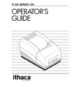
PRINTER CONNECTIONS
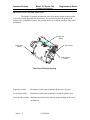
Up to four cables can be connected to the printer, providing for power, host
interface, and up to 2 cash draw (with a “Y” Connector) support. They all connect in the
back of the printer, which is shown below:
Power Connector
Cash Drawer Connector
Interface Connector
Back of Printer
CONNECTING THE INTERFACE CABLE
You need an appropriate interface cable. The parallel interface requires a straight
through 25 pin connector, with male termination on the printer end, or a 36 pin Centronix
Cable. See the interface section for complete pin definition details. The serial interface
requires a DB25 to DB9, or DB9 to DB9 pin null modem crossover cable, with a DB9 pin
female terminal on the printer end, and the appropriate gender connector at the host
computer end. See the communication section for complete pin definition details.
1. Plug the cable connector securely into the printer’s interface
connector.
2. Attach the other end of the cable to the appropriate terminal on the computer.
09/26/2000
Page 3 -3
General Information
Model 181 Series 180
Programmer’s Guide
TransAct Technologies
CONNECTING THE CASH DRAWER CABLES
The cash drawer option, (with a ”Y” connector) allows up to two cash drawers to
be connected to the printer in a system with a PC that has no connectors for the
cash drawer cables.
The cash drawers are operated by software commands from the host system
through the printer. For additional information on the printer commands used by
the host system to activate the cash drawer, see “Control Code Library” later in
this manual.
1. Plug the cash drawer cable into the connector on the printer.
The connector is a standard phone connector.
Note: The following illustration shows the pin outs for the cash drawer
connectors, as viewed from the rear of the unit.
Cash Drawer
123456
1
2
3
4
5
6
Power Connector
EPSON
ITHACA
STAR
J7 PIN # 1-2, 3-4, 5-6, 7-8,
9-10 *
Frame Ground
Dwr 1 Drive – (GND switched)
Status Switch +
Dwr Drive + (24 volt)
Dwr 2 Drive – (GND switched)
Ground
J7 PIN # 2-3, 4-5, 6-7, 8-9,
10-11
Dwr 2 Drive – (GND switched)
Status Switch +
Ground
Dwr Drive + (24 volt)
Dwr 1 Drive – (GND switched)
Frame Ground
J7 PIN # 5-6, 7-8, 9-10, 11-12,
13-14
Frame Ground
Dwr 1 Drive – (GND switched)
Dwr Drive + (24 volt)
Dwr Drive + (24 volt)
Dwr 2 Drive – (GND switched)
Status Switch +
* Default
Page 3 -4
09/26/2000
Programmer’s Guide
Model 181 Series 180
General Information
TransAct Technologies
Warning:
Use a drawer that matches the printer specification. Using an improper drawer
may damage the drawer as well as the printer.
Caution:
Do not connect a telephone line to the drawer kick-out connector; otherwise the
printer and the telephone line may be damaged.
CONNECTING THE POWER SUPPLY
Use the optional Ithaca Phi-Hong PSA-53 or equivalent power supply for your
printer. The following illustration shows the power cable connector and pin
assignments. The power cable connector is a 3 pin mini DIN plug and is located in the
small cavity under the printer.
Earth Ground
24 Volt supply 24 Volt supply +
Warning:
Make sure that you use the Ithaca Phi Hong PSA-53 power supply or equivalent.
Using an incorrect power supply may cause fire or electrical shock.
Caution:
If the power supply’s rated voltage and your outlet’s voltage do not match,
contact your dealer for assistance. Do not plug in the power cord. Otherwise, you may
damage the power supply or the printer.
1. Make sure that the power supply’s power cord is unplugged from the electrical
outlet.
2. Check the label on the power supply to make sure that the voltage required by
the power supply matches that of your electrical outlet.
3. Plug in the power supply’s cable as shown below.
Note: To remove the DC cable connector grasp the connector at the arrow and
pull it straight out.
09/26/2000
Page 3 -5
General Information
Model 181 Series 180
Programmer’s Guide
TransAct Technologies
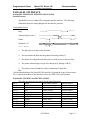
INSTALLING OR REPLACING THE PAPER ROLL
Note: Be sure to use paper rolls that meet specifications.
1. Open the printer cover by pulling the handle on the front of the printer toward you.
2. If the paper is being changed remove the empty paper core from the spindle.
3. Insert the new paper roll onto the spindle with the paper feeding over the top.
4. Push the paper roll down into the paper well.
5. Pull the paper edge over the platen and past the edge of the printer cover.
6. Close the cover making sure that the paper edge is protruding from the front of the
printer. Press the Feed button to check for proper operation.
Spindle
Paper Feed Button
Platen
Front Cover
Front of Printer
Page 3 -6
09/26/2000
Programmer’s Guide
Model 181 Series 180
General Information
TransAct Technologies
SELF TEST MODE
Description
The Ithaca Model 181 thermal printer has the ability to print self-test ticket(s) on powerup upon command. The self-test prints a variety of information about the printer
operating settings and configuration. The information provided by the self-test is listed
below, in order:
CONFIGURATION TICKET
Model number
Serial number
Operating system type and version.
Current emulation mode (Epson TM-T8x, Axiohm 7193, or Epson Tm-300)
Part intensity
Interface configuration
Hexdump mode status (on, off)
Carriage return control
Input buffer capacity
User definable RAM buffer capacity
Non-volatile eeprom buffer capacity
Contents of the eeprom buffer (Bit-image, Character set)
Startup macro definition status (yes, no)
Additional Information
Auto Cutter (enabled, disabled)
Statistical information
PRINT TICKETS
The configuration ticket is followed by print tickets: tickets printed at 15 CPI and
printed at 20 CPI. Each ticket prints 1 of 5 code pages available at that pitch.
09/26/2000
Page 3 -7
General Information
Model 181 Series 180
Programmer’s Guide
TransAct Technologies
CONFIGURATION MODE
Description
The Ithaca Model 181 thermal printer has many options and features that are user
configurable. Unlike most printers that use dip switches to control these settings, the
Model 181 has been equipped with an automated configuration mode. By powering the
printer on in a special sequence, the printer enters the configuration mode. In this mode,
the printer’s current settings are printed one at a time. By pressing the FEED button for
a short duration, the printer cycles through the settings modes. When the setting for the
item you desire has been selected, long FEED button presses will cause the printer to
move on to the next setting for the active mode. When all options have been configured
the user can enter the “Exit and Save Selection.” A long presses of the FEED button
will write the options permanently to non-volatile eeprom memory. See Configuration
Options for an ordered list of options and their associated settings.
ENTERING THE CONFIGURATION MODE
Follow the steps below to enter the configuration mode:
1.
2.
3.
4.
5.
6.
7.
8.
Power the printer off if it is not already off.
Open the cover.
Power the printer on while holding down the FEED button.
Wait until the status LED blinks a cover open condition (see Appendix B).
Release the FEED button.
Load the printer with paper if it is not already loaded.
Close the cover.
The printer will print a few lines of instructions followed by:
Short Press to enter config. mode now.
Long Press to exit config. mode now.
If the printer is powered off at any time during the configuration mode, no changes
will be saved.
The initial setting displayed with each option reflects the various configurable areas.
If you do not wish to change a setting, simply supply short presses of the FEED
button until the “Exit Without Saving” config. option is displayed. Then apply a long
press of the FEED button.
The printer does not have to be connected to a host computer to use the configuration
mode.
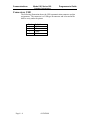
CONFIGURATION OPTIONS
Page 3 -8
09/26/2000
Programmer’s Guide
Model 181 Series 180
General Information
TransAct Technologies
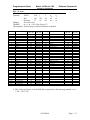
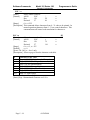
The tables below depict the Configurable Modes, in order, presented by the configuration
mode. Each options table shows the settings available for a given option, as well as the
default setting where applicable:
Configurable mode
Communication
Emulation
Configurable variable
Baud Rate
Possible selection
38400
19200
9600
4800
Word Format
8,n,1
7,o,1
7,e,1
8,n,2
8,o,1
8,e,1
Flow Control
DTR/DSR
CTS/RTS
CTS/RTS & DTR/DSR
XON/XOFF
Data Receive char
?
Serial Plug & Play
Enabled
Disabled
Emulation Mode
Default M80
Ithaca M50
Axiohm 7193
Epson TM-T88
Epson TM-T85
Epson TM-300
Many Selections
Language Set Active
Graphic buffering
Enabled
Disabled
Euro Substitution
Enabled
09/26/2000
Page 3 -9
General Information
Model 181 Series 180
Programmer’s Guide
TransAct Technologies
Disabled
Hardware
CR Control
Perform CR
Perform LF
Ignore CR
Auto Cutter
Enabled
Disabled
Auto Cutter Mode
Mode 1- Mode 5
Print Head Intensity
Setting 1 - Setting 5
Off Line status
Normal
Buffer full only
Automatic Status Back
Buffers
Input Buffer size
User defined Buffer size
Enabled
Disabled
Range 8k-100k
Range
Hex mode print
Hex mode
Active
Page 3 -10
09/26/2000
Reference Information
Model 181 Series 180
Programmer’s Guide
TransAct Technologies
CHAPTER 2
Reference Information
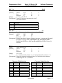
Printing Specifications
Printing method:
Thermal line printing
Dot density:
203 dpi x 203 dpi [8 dots/mm]
Printing direction:
Unidirectional with friction feed
Printing width:
72 mm (2.83"), 576 dot positions
Characters per line
(default):
(Font A) 44
(Font B) 57
Character spacing
(default):
0.25 mm (.01") (2 dots) (Font A)
0.25 mm (.01") (2 dots) (Font B)
Programmable by control command.
Printing speed:
Approximately 24 lines/second
(1/6" inch feed, at 24V, 20o C)
Approximately 101.6 mm/second
(approximately 4"/second)
NOTES:
Printing speed may be slower, depending on the data transmission speed and the
combination of control commands.
The printer switches the mode of the printing speed automatically.
There may be variations in printing after switching the mode of the printing
speed. To prevent this for logo printing, using a downloaded bit image is
recommended. (Change in printing speed does not occur during downloaded bit
image printing).
Paper feeding speed:
Approximately 101.6 mm/second
(approximately 4.00"/second)
continuous printing
09/26/2000
Page 4 - 1
Programmer’s Guide
Model 180 Series 181
Reference Information
TransAct Technologies
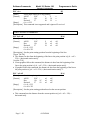
Line Spacing (default):
Epson TM-T8x, Epson TM-300 mode: 4.23 mm (1/6")
Axiohm 7193 mode: 3.35 mm (1/7.56")
Programmable by control command.
Number of characters:
Alphanumeric characters: 95
International characters: 32
Extended graphics: 128 x 7 pages
(including one space page)
Character structure:
Font A: 13 x 24 (including 2-dot spacing
in horizontal)
Font B: 10 x 24 (including 2-dot spacing
in horizontal)
Font A is the default
Standard
WxH
(mm)
Font A
13 × 24
Font B
10 × 24
1.38 × 3.00
(.06” × .12”)
1.00 × 3.00
(.04” × .12”)
CPL
44
57
Double-height
Double-width
WxH
(mm)
CPL
WxH
(mm)
CPL
44
2.75 × 3.00
(.11” × .12”)
2.00 × 3.00
(.08” × .12”)
22
1.63 × 6.00
(.06” × .24”)
1.00 × 6.00
(.04” × .24”)
57
* CPL = Characters Per Line
* Space between characters is not included
* Characters can be scaled up to 64 times as large as the standard sizes.
Page 4 -2
09/26/2000
28
Double-width/
Double-height
WxH
CPL
(mm)
2.75 × 6.00
(.11” × .24”)
2.00 × 6.00
(.08” × .24”)
22
28
Reference Information
Model 181 Series 180
Programmer’s Guide
TransAct Technologies
PAPER SPECIFICATIONS
Paper roll (single-ply):
Single ply fax grade thermal receipt paper
Thermal sensitive layer on the outside of roll
Paper thickness: .06 mm to .09 mm (.0024 to .0035 in.)
Paper width: 80 mm - 1mm + 0 mm (3.15 in. - .04 in. +.0 in.)
Maximum roll diameter: 83 mm (3.25 in.)
Outside core diameter: 19 mm minimum (.750 in. minimum)
Inside core diameter: 12.5 mm + 2.5 mm (.492 in. + .098 in.)
Paper to be free to release from core
Leading edge of paper to be free of glue or other contaminates
09/26/2000
Page 4 - 3
Programmer’s Guide
Model 180 Series 181
Reference Information
TransAct Technologies
ELECTRICAL CHARACTERISTICS
Supply Voltage:
24 VDC 5% (optional power supply: Ithaca
Phi Hong PSA- 53
Current
consumption:
Operating: Mean: approximately 2A.
Peak: Approximately 5.0A.
Standby: Mean: approximately 0.2A.
Note: Maximum 1A for drawer kick-out driving.
RELIABILITY
Print head life:
100 million pulses,
100 km
100 million cuts
Cutter life:
ENVIRONMENTAL CONDITIONS
Temperature:
Humidity:
Page 4 -4
Operating:
0 to 40C (32 to 104F)
Storage:
-40 to 70C (-40 to 158F)
(except for paper)
Operating:
10% to 90% RH, non-condensing
Storage:
5% to 90% RH, non-condensing
(except for paper)
09/26/2000
Programmer’s Guide
Model 181 Series 180
Software Commands
TransAct Technologies
CHAPTER 3
Commands
Emulation Modes and Available Commands
The Ithaca Model 181 thermal printer is capable of emulating an Epson TM-T8x, or a
TM-300B series printer and Axiohm 7193 printer. The Series 180 command set is a
combination of the Epson TM-T8x and Axiohm 7193 command sets. Though the Epson
TM-8x and Axiohm 7193 share many of the same commands, they do not all produce the
same results. Therefore, to ensure complete compatibility, the Series 180 must be
configured specifically for either Epson TM-T8x emulation or Axiohm 7193 emulation.
The current emulation mode can be obtained at any time by performing a Self-test
(Chapter 1), and may be changed at any time via the Configuration Mode (Chapter 1).
The following Epson TM-300 commands are not supported. Print Head Return Home,
Set/Cancel Unidirectional Printing, Select Paper Type, Print and Reverse Feed Lines, and
Set Validation Paper Waiting Time.
All of the commands supported by the Model 181 are available at any time, regardless of
the current emulation mode, unless otherwise noted. When the execution of a given
command differs depending upon the current emulation mode, it will be noted.
COMMAND TITLE LINE
The following line depicts the title line of a typical command:
Command Name
[ Origin ]
Command Name is the name of the command.
Origin specifies which printers command set the command comes from.
Origin may take on any combination of the following values:
B
E
A
I
*
=
=
=
=
=
Epson TM-300B command set.
Epson TM-T8x command set.
Axiohm 7193 command set.
Ithaca Series 180 command set.
Command has different functions depending upon the current
emulation mode.
09/26/2000
Page 5 - 1
Software Commands
Model 181 Series 180
Programmer’s Guide
TransAct Technologies
COMMAND NOTATION
[Name]
[Format]
[Range]
[Default]
[Description]
[Axiohm 7193]
[Epson TM-T8x]
[Epson TM-300B]
The name of the command.
The code sequence.
ASCII indicates the ASCII equivalents.
Hex indicates the hexadecimal equivalents.
Decimal indicates the decimal equivalents.
[ ] k indicates the contents of the [ ] should be repeated k
times.
Gives the allowable ranges for the arguments.
Shows the defaults used by the command.
Describes the function of the command.
Information that follows applies only when in
Axiohm 7193 emulation mode.
Information that follows applies only when in
Epson TM-T8x emulation mode.
Information that follows applies only when in Epson TM300B emulation mode.
EXPLANATION COMMANDS
MSB
LSB
ASB
HRI
(k)
HEX
DEC
Page 5 - 2
Most Significant Bit
Least Significant Bit
Automatic Status Back
Human Readable Interpretation
Number of bytes specified is × 1024
Hexadecimal number system, base 16
Decimal number system, base 10
09/26/2000
Programmer’s Guide
Model 181 Series 180
Software Commands
TransAct Technologies
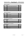
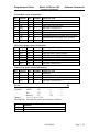
Supported Commands
Print and Feed Commands
Command
Name
Page
Number
LF
CR
ESC J
ESC d
DC4
NAK
ETB
Print and line feed
Print and carriage return
Print and feed paper
Print and feed n lines
Feed n print lines
Feed n Dot Rows
Print
5-7
5-7
5-7
5-8
5-8
5-8
5-7
Line Spacing Commands
Command
Name
Page
Number
ESC 2
ESC 3
SYN
Select default line spacing
Set line spacing
Add n extra dot rows
5-8
5-8
5-9
Character Commands
Command
Name
Page
Number
ESC SP
ESC %
ESC &
ESC ?
ESC R
ESC [ T
ESC ^ n
ESC t
ESC !
ESC ESC E
ESC G
ESC {
ESC V
ESC DC2
GS !
GS B
DC2
DC3
ESC SYN
Set right-side character spacing
Select/cancel user-defined character sets
Define user-defined characters
Cancel user-defined characters
Select an international character set
Select character code table
Print control character
Select character code table
Select print mode(s)
Turn underline mode on/off
Turn emphasized mode on/off
Turn double-strike mode on/off
Turn upside-down printing mode on/off
Turn 900 rotation mode on/off
Turn 900 counter-clockwise rotation mode on/off
Select character size
Turn white/black reverse printing mode on/off
Select double-wide characters
Select single-wide characters
Select pitch (column width)
5-9
5-10
5-10
5-11
5-12
5-13
5-14
5-14
5-15
5-15
5-16
5-16
5-16
5-17
5-17
5-17
5-18
5-18
5-18
5-18
09/26/2000
Page 5 - 3
Software Commands
Model 181 Series 180
Programmer’s Guide
TransAct Technologies
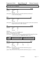
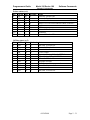
Panel Button Commands
Command
Name
Page
Number
ESC c 5
Enable/disable panel buttons
5-19
Paper Sensor Commands
Command
Name
Page
Number
ESC c 3
ESC c 4
Select paper sensor(s) to output paper end signals
Select paper sensor(s) to stop printing
5-19
5-20
Print Position Commands
Command
Name
Page
Number
ESC $
ESC \
ESC a
HT
ESC D
GS L
GS W
ESC DC4
Set absolute print position
Set relative print position
Select justification
Horizontal tab
Set horizontal tab positions
Set left margin
Set printing area width
Set column
5-20
5-20
5-21
5-21
5-21
5-22
5-22
5-22
Bit-image Commands
Command
Name
Page
Number
ESC *
ESC K
ESC L
ESC Y
GS *
GS /
Select bit-image mode
Select 8-dot single-density bit-image mode
Select 8-dot double-density bit-image mode
Select 8-dot double-density bit-image mode
Define downloaded bit-image in the RAM buffer
Print downloaded/stored bit-image
5-23
5-24
5-24
5-25
5-25
5-26
Page 5 - 4
09/26/2000
Programmer’s Guide
Model 181 Series 180
Software Commands
TransAct Technologies
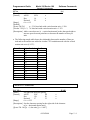
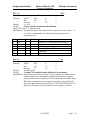
Status Commands
Command
Name
Page
Number
GS a
GS r
DLE EOT
ESC u1
ESC u1
ESC u 01
ESC v
Enable/Disable Automatic Status Back (ASB)
Transmit status
Real-time status transmission
Transmit peripheral device status
Request alternate status
Transmit cash drawer status
Transmit printer status
5-28
5-29
5-30
5-33
5-33
5-34
5-32
1
Command has different functions depending upon the current emulation mode.
Bar Code Commands
Command
Name
Page
Number
GS h
GS w
GS k
GS H
GS f
Set bar code height
Set bar code width
Print bar code
Select printing position of HRI characters
Select font HRI characters
5-38
5-35
5-36
5-38
5-38
Macro Function Commands
Command
Name
Page
Number
GS :
GS ^
GS _
Start/end macro definition
Execute macro
5-38
5-39
5-40
Delete startup macro definition
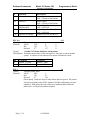
Mechanism Control Commands
Command
Name
Page
Number
GS V
ESC i
EM
SUB
Select cut mode and cut paper
Partial Knife Cut
Full knife cut
Partial knife cut
5-40
5-40
5-41
5-41
09/26/2000
Page 5 - 5
Software Commands
Model 181 Series 180
Programmer’s Guide
TransAct Technologies
Miscellaneous Commands
Command
Name
Page
Number
GS P
ESC @
DLE
GS I
ESC p
ESC =
DLE ENQ
ESC ‘
GS E
Set horizontal and vertical motion units
Initialize printer
Clear printer
Transmit printer ID
Generate pulse
Set peripheral device
Real-time request to printer
Copy user defined storage buffers
Set
5-41
5-41
5-41
5-42
5-42
5-43
5-43
5-44
5-44
Page 5 - 6
09/26/2000
Programmer’s Guide
Model 181 Series 180
Software Commands
TransAct Technologies
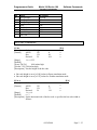
Print and Feed Commands
LF
[Name]
[Format]
[EAB]
Print and line feed
ASCII
LF
Hex
0A
Decimal
10
[Description] Prints the data in the print buffer and feeds one line based
on the current line spacing.
ETB
[Name]
[Format]
[A]
Print
ASCII
ETB
Hex
17
Decimal
23
[Description] Prints one line from the buffer and feeds paper one line at the current line
height (functions same as LF command).
CR
[Name]
[Format]
[EAB]
Print and carriage return
ASCII
CR
Hex
0D
Decimal
13
[Default]
[Epson TM-T8x, Epsom TM-300] CR ignored.
[Axiohm 7193]Functions same as LF.
[Description] The table below describes the operation of the LF command based upon
its default setting in the Configuration Mode (Chapter 1):
Paper
Automatic line feed enabled
Paper roll Functions as same as LF
Automatic line feed disabled
Ignored
ESC J n
[Name]
[Format]
[EA]
Print and feed paper
n
ASCII
ESC
J
n
Hex
1B
4A
n
Decimal
27
74
[Range]
0 n 255
[Description] Prints the data in the print buffer and feeds the paper [n ×
vertical motion unit].
[Epson 300B] Prints the data in the print buffer and feeds the paper [n × 1/144 in]
09/26/2000
Page 5 - 7
Software Commands
Model 181 Series 180
Programmer’s Guide
TransAct Technologies
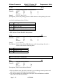
ESC d n
[Name]
[Format]
[EAB]
DC4 n
[Name]
[Format]
[A]
Print and feed n lines
n
ASCII
ESC
d
n
Hex
1B
64
n
Decimal
27
100
[Range]
0 n 255
[Description] Prints the data in the print buffer and feeds n lines.
Feed n print lines
n
ASCII
DC4
n
Hex
14
n
Decimal
20
[Range]
0 n 255
[Description] Feeds the paper n lines at the current line height without printing.
NAK n
[Name]
[Format]
[A]
Feed n Dot Rows
n
ASCII
NAK
n
Hex
15
n
Decimal
21
[Range]
0 n 255
[Description] Feeds the paper n dot rows [n × vertical motion unit] inches without
printing.
Line Spacing Commands
ESC 2
[Name]
[Format]
[EAB]
ESC 3 n
[Name]
[Format]
[EAB]
Select default line spacing
ASCII
ESC
2
Hex
1B
32
Decimal
27
50
[Description] Sets the line spacing to 1/6 inch.
Set line spacing
ASCII
ESC
Hex
1B
Decimal
27
0 n 255
[Range]
[Description]
[Epson TM-T8x]
[Axiohm 7193]
[Epson TM-300B]
Page 5 - 8
3
33
51
n
n
n
Sets the line spacing to [n × vertical motion unit].
Sets the line spacing to [n × (1/360”)].
Sets the line spacing to [n × (1/144”)]
09/26/2000
Programmer’s Guide
Model 181 Series 180
Software Commands
TransAct Technologies
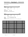
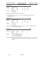
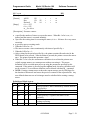
SYN n
[Name]
[Format]
[A]
Add n extra dot rows
ASCII
SYN
Hex
16
Decimal
22
0 n 12
n
n
n
[Range]
[Default]
n = 23, 6 lines/inch with vertical motion unit = 1/360.
[Epson TM-T8x]
[Axiohm 7193]n = 2, 7.6 lines/inch with vertical motion unit = 1/152.
[Description] Adds n extra dot rows [n × vertical motion unit] to the character height to
increase space between print lines or decrease the number of lines per
inch.
The following sample table shows the relationship between the number of lines per
inch and each extra dot row added in Axiohm 7193 emulation mode with the vertical
motion unit set to (1/152”):
Extra Rows
0
1
2
3
4
5
6
7
8
9
10
11
12
Lines Per Inch
8.5
8.0
7.6
7.2
7.0
6.6
6.3
6.1
5.9
5.6
5.4
5.2
5.1
Dot Rows
18
19
20
21
22
23
24
25
26
27
28
29
30
Character Commands
ESC SP n
[Name]
[Format]
[EAB]
Set right-side character spacing
n
ASCII
ESC
SP
n
Hex
1B
20
n
Decimal
27
32
[Range]
0 n 255
[Description] Sets the character spacing for the right side of the character
to [n × horizontal motion unit].
[Epson TM -300] [n × ½ dot units] [n = 1/406”]
09/26/2000
Page 5 - 9
Software Commands
Model 181 Series 180
Programmer’s Guide
TransAct Technologies
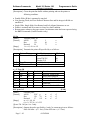
ESC % n
[Name]
[Format]
[EAB]
Select/cancel user-defined character sets
n
ASCII
ESC
%
n
Hex
1B
25
n
Decimal
27
37
See table below.
[Range]
[Epson TM -300] LSB only used.
[Description] Selects or cancels a user-defined character set as defined below:
Table of n
Hex Decimal
00
0
01
1
02
2
41
65
Function
Selects code page 437 and turns off user defined set.
Selects user defined character set in the RAM buffer
Selects code page 850 and turns off user defined set.
Selects user defined character set in non-volatile eeprom
buffer.
If the user defined character set in RAM is selected and the set does not exist, an
empty set will be created. Any user defined bit-image will be erased. Any characters
referenced that are not defined will be replaced as follows: equivalent code page 437
character in Axiohm 7193 emulation; equivalent current code page character in Epson
TM-T8x emulation.
If the user defined character set in the non-volatile eeprom buffer is selected and the
set does not exist, this command will be ignored (See the GS ‘ command for saving a
user defined character set in the RAM buffer to the non-volatile eeprom buffer).
ESC & y cl c2 [x1 d1...d(y × x1]...[xk d1...d(y × xk)]
[EA]
[Name]
Define user-defined characters
[Format]
ASCII
ESC & y c1 c2 [x1 d1...d(y × x1)]...[xk d1...d(y × xk)]
Hex
1B 26 y c1 c2 [x1 d1...d(y × x1)]...[xk d1...d(y × xk)]
Decimal
27
38 y c1 c1 [x1 d1...d(y × x1)]...[xk d1...d(y × xk)]
y=3
[Range]
0 x 13 Font A (13 × 24)
0 x 10 Font B (10× 24)
0 d1 ... d(y × xk) 255
k = c2-c1+1
[Axiohm 7193]
32 c1 c2 254
[Epson TM-T8x]
32 c1 c2 126
[Epson TM -300] y=2, 32 c1 c2 126
[Description] Defines user-defined characters.
y specifies the number of bytes in the vertical direction.
Page 5 - 10
09/26/2000
Programmer’s Guide
Model 181 Series 180
Software Commands
TransAct Technologies
c1 specifies the beginning character code for the definition, and c2 specifies the final
code.
x specifies the number of dots in the horizontal direction.
d is the dot data for the characters. The dot pattern is in the horizontal direction from
the left side. Any remaining dots on the right side are blank.
The allowable character code range differs between Epson and Axiohm emulation.
See [Range] above.
The data to define a user-defined character is (y × x) bytes.
Set a corresponding bit to 1 to print a dot or 0 to not print a dot.
In Epson emulation mode, there is a unique user defined character set for each pitch.
In Axiohm emulation mode, both pitches share the same user defined character set.
ESC & s n m [ a [ p ] s x a ] m-n+1
[E]
[Name]
Define user-defined characters
[Format]
1B 26 s n> m[a p1 p2 ps x a] m-n + 1
[Range]
s=2
32 n m 126
0 a 12 (9 x 9 font)
0 a 10 (7 x 9 font)
0 p1 ps x a 255
[Description] Defines user-defined characters for ANK characters codes.
The “s” specifies the number of bytes in the vertical direction.
The “n” specifies the beginning ASCll code for the definition, and “m” the final code.
If only one characters is defined, use n = m.
The allowable characters code range is from ASCll code 20 to 7E. When receive
buffer capacity is 1 Kbyte, the maximum number of characters is 9: when receive
buffer capacity is 40 bytes, the maximum number of characters is 44.
When the maximum number of user-defined characters has been defined, redefinition
of the defined ASCll codes is possible, but definition of new ASCll codes is not.
The “a” specifies the number of dots in the horizontal direction.
The “p” is the dot data for the characters. The dot pattern is the horizontal direction
from the left side. Any remaining dots on the right side are blank.
After user-defined characters are defined once, they are available until another
definition is made, the ESC @ command is executed, the printer is reset, or the power
is turned off.
[Default]
The same as the internal characters set.
[Notes]
Horizontal adjacent dots cannot be printed.
Only the top bit is valid in the secondary data bytes in the vertical direction.
09/26/2000
Page 5 - 11
Software Commands
Model 181 Series 180
Programmer’s Guide
TransAct Technologies
[Reference] ESC %
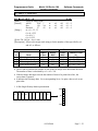
ESC ? n
[Name]
[Format]
[E]
Cancel user-defined characters
ASCII
ESC
?
Hex
1B
3F
Decimal
27
63
n
n
n
[Range]
[Axiohm 7193]
32 n 254
[Epson TM-T8x]
32 n 126
[Description] Cancels user-defined characters.
ESC R n
[Name]
[Format]
[EAB]
Select an international character set
n
ASCII
ESC
R
n
Hex
1B
52
n
Decimal
27
82
[Range]
0 n 10 - S033000 Firmware 1 Meg
[Range]
0 n 74 - S033001 Firmware 2 Meg
n=0
[Default]
[Description] Selects an international character set n from the following table:
Country
ASCII
French
German
British
Danish I
Swedish I
Italian
Spanish I
Japanese
Norwegian
Danish II
Spanish II
Latin American
French Canadian
Dutch
Swedish II
Swedish III
Swedish IV
Turkish
Swiss I
Epson ID
0
1
2
3
4
5
6
7
8
9
10
11
12
13
14
15
16
17
18
19
Page 5 - 12
Country
Swiss II
Cyrillic II-866
Polska Mazovia
ISO Latin 2
Serbo Croatic I
Serbo Croatic II
Multilingual
Norway
Portugal
Turkey
Greek 437
Greek 928
Greek 437 CYPRUS
ECMA-94
Canada French
Cyrillic I-855
Cyrillic II-866
East Europe Latin II-852
Greek 869
Windows East Europe
Epson ID
20
21
22
23
24
25
26
27
28
29
38
39
41
42
43
44
45
46
47
49
09/26/2000
Country
Windows Greek
Latin 5 (Windows Turkey)
Windows Cyrillic
Hungarian CWI
Kamenicky (MJK)
ISO Latin 4 (8859/4)
Turkey_857
Roman-8
Hebrew NC (862)
Hebrew OC
Windows Hebrew
KBL- Lithuanian
Publisher
Ukrainian
ISO Latin 6 (8859/10)
Windows Baltic
Cyrillic-Latvian
Bulgarian
Icelandic-861
Baltic 774
Epson ID
50
51
52
54
55
56
57
58
60
61
62
63
64
66
67
68
69
72
73
74
Programmer’s Guide
Model 181 Series 180
Software Commands
TransAct Technologies
ESC [ T nH nL
[Name]
Select character code table
[Format]
ASCII
ESC [
T
nH
nL
Hex
1B
5B
54
nH
nL
Decimal
27
91
84
nH
nL
See table below
[Range]
[Default]
nH = 1, nL = 181 (Code Page 437)
[Description] Selects a page n from the character code table.
Code Page
64
65
66
67
68
69
70
71
72
73
74
75
76
77
78
79
80
81
90
91
437
774
850
852
855
857
860
861
862
863
865
866
Country
USA (Slashed 0)
USA(Unslashed 0)
British
German
French
Swedish I
Danish
Norwegian
Dutch
Italian
French Canadian
Spanish
Swedish II
Swedish III
Swedish IV
Turkish
Swiss I
Swiss II
Publisher
Welsh
USA
Baltic 774
Multilingual
East Europe Latin II852
Cyrillic I-855
Turkey 857
Portugal
Icelandic-861
Hebrew NC (862)
Canada French
Norway
Cyrillic II-866
Decimal
<nh> <nl>
0,64
0,65
0,66
0,67
0,68
0,69
0,70
0,71
0,72
0,73
0,74
0,75
0,76
0,77
0,78
0,79
0,80
0,81
0,90
0,91
1,181
3,6
3,82
3,84
Hex
<nh> <nl>
0H,040H
0H,041H
0H,042H
0H,043H
0H,044H
0H,045H
0H,046H
0H,047H
0H,048H
0H,049H
0H,04AH
0H,04BH
0H,04CH
0H,04DH
0H,04EH
0H,04FH
0H,050H
0H,051H
0H,05AH
0H,05BH
1H,0B5H
3H,006H
3H,052H
3H,054H
Code Page
Country
869
874
895
1008
1009
1011
1012
1013
1014
1015
1016
1017
1018
1019
1020
1021
1022
1024
1026
1027
1028
1029
1030
1031
Greek 869
Thailand
Kamenicky (MJK)
Greek 437
Greek 928
Greek 437 CYPRUS
Turkey
Cyrillic II-866
Polska Mazovia
ISO Latin 2
Serbo Croatic I
Serbo Croatic II
ECMA-94
Windows East Europe
Windows Greek
Latin 5 (Windows Turkey)
Windows Cyrillic
Hungarian CWI
ISO Latin 4 (8859/4)
Ukrainian
Roman-8
ISO Latin 6 (8859/10)
Hebrew NC (862)
Hebrew OC
3,87
3,89
3,92
3,93
3,94
3,95
3,97
3,98
3H,057H
3H,059H
3H,05CH
3H,05DH
3H,05EH
3H,05FH
3H,061H
3H,062H
1032
1033
1034
1035
1072
Windows Hebrew
KBL- Lithuanian
Windows Baltic
Cyrillic-Latvian
Bulgarian
Decimal
<nh> <nl>
3,101
3,106
3,127
3,240
3,241
3,243
3,244
3,245
3,246
3,247
3,248
3,249
3,250
3,251
3,252
3,253
3,254
4,0
4,2
4,3
4,4
4,5
4,6
4,7
Hex
<nh> <nl>
3H,065H
3H,06AH
3H,07FH
3H,0F0H
3H,0F1H
3H,0F3H
3H,0F4H
3H,0F5H
3H,0F6H
3H,0F7H
3H,0F8H
3H,0F9H
3H,0FAH
3H,0FBH
3H,0FCH
3H,0FDH
3H,0FEH
4H,000H
4H,002H
4H,003H
4H,004H
4H,005H
4H,006H
4H,007H
4,8
4,9
4,10
4,11
4,48
4H.008H
4H,009H
4H,00AH
4H,00BH
4H,030H
The Code page Field is a 16 Bit field that is equivalent to the code page number. (ex. 1
* 256 + 181 = 437)
09/26/2000
Page 5 - 13
Software Commands
Model 181 Series 180
Programmer’s Guide
TransAct Technologies
ESC ^ n
[Name]
[Format]
Print Control Character
n
ASCII
ESC
^
n
Hex
1B
5E
n
Decimal
27
94
[Range]
0 n 255
[Description] This command allows characters from 0 - 31 codes to be printed. In
normal operation characters from 0 - 31 are control characters. This
command turns off control code translation for character n.
ESC t n
[Name]
[Format]
[E]
Select character code table
n
ASCII
ESC
t
n
Hex
1B
74
n
Decimal
27
116
[Range]
0 n 5, n = 255
n=0
[Default]
[Epson TM -300] n = 0 or 1 only
[Description] Selects a page n from the character code table.
n
0
1
2
3
4
5
255
Character Code Table
Page 0 (PC437 (U.S.A., Standard Europe))
Page 1 (PC850 (Multilingual)) (see note)
Page 2 (PC850 (Multilingual))
Page 3 (PC860 (Portuguese))
Page 4 (PC863 (Canadian-French))
Page 5 (PC865 (Nordic))
Page 255 (Space page)
[Notes] Page 1 International Character set U.S.A.
Page 5 - 14
09/26/2000
Programmer’s Guide
Model 181 Series 180
Software Commands
TransAct Technologies
ESC ! n
[Name]
[Format]
[EAB]
Select print mode(s)
ASCII
ESC
!
Hex
1B
21
Decimal
27
33
[Range]
0 n 255
[Epson TM -300] Bit 3 underfined.
[Description] Selects print mode(s) using n as follows:
Bit
0
1, 2
3
4
5
6
7
Off/On
Off
On
Off
On
Off
On
Off
On
Off
On
Hex
00
01
00
08
00
10
00
20
00
80
Decimal
0
1
0
8
0
16
0
32
0
128
n
n
n
Function
Character font A (13 × 24)
Character font B (10 × 24).
Undefined.
Emphasized mode not selected.
Emphasized mode selected.
Double-height mode not selected.
Double-height mode selected.
Double-width mode not selected.
Double-width mode selected.
Undefined.
Underline mode not selected.
Underline mode selected.
Determine the values of n by adding the values of all the characteristics you want to
select.
ESC - n
[E]
[Name]
Turn underline mode on/off
n
[Format]
ASCII
ESC
n
Hex
1B
2D
n
Decimal
27
45
[Range]
0 n 2, 48 n 50
[Description] Turns underline mode on or off, based on the following
values of n:
n
0, 48
1, 49
2, 50
Function
Turns off underline mode
Turns on underline mode (2-dots thick)
Turns on underline mode (2-dots thick)
09/26/2000
Page 5 - 15
Software Commands
Model 181 Series 180
Programmer’s Guide
TransAct Technologies
ESC E n
[Name]
[Format]
[E]
Turn emphasized mode on/off
ASCII
ESC
E
Hex
1B
45
Decimal
27
69
[Range]
0 n 255
[Description] Turns emphasized mode on or off
n
n
n
When the LSB is 0, emphasized mode is turned off.
When the LSB is 1, emphasized mode is turned on.
ESC G n
[Name]
[Format]
[E]
Turn double-strike mode on/off
ASCII
ESC
G
Hex
1B
47
Decimal
27
71
[Range]
0 n 255
[Description] Turns double-strike mode on or off.
n
n
n
When the LSB is 0, double-strike mode is turned off.
When the LSB is 1, double-strike mode is turned on.
ESC { n
[Name]
Turns upside-down printing mode on/off
n
[Format]
ASCII
ESC
{
n
Hex
1B
7B
n
Decimal
27
123
[Range]
0 n 255
[Description] Turns upside-down printing mode on or off.
[EB]
When the LSB is 0, upside-down printing mode is turned off.
When the LSB is 1, upside-down mode is turned on.
[Axiohm 7193]
Counter-clockwise rotation, ESC DC2, is turned off when upside-down printing mode
is turned on.
Page 5 - 16
09/26/2000
Programmer’s Guide
Model 181 Series 180
Software Commands
TransAct Technologies
ESC V n
[Name]
[Format]
[EAI]
Turn 900 rotation mode on/off
ASCII
ESC
V
Hex
1B
56
Decimal
27
86
n = 0, 1, 2, 48, 49, 50
[Range]
[Description] Turns 900 clockwise rotation mode on/off
n is used as follows:
n
0, 48
1, 49
2, 50
n
n
n
Function
Turns off all rotation modes
Turns on 900 clockwise rotation mode
Turns on 900 counter-clockwise rotation mode
ESC DC2
[Name]
[Format]
[A]
Turn 900 counter-clockwise rotation mode on/off
ASCII
ESC
DC2
Hex
1B
12
Decimal
27
18
[Description] Rotates characters 90 degrees counter-clockwise. It remains in effect until
the printer is reset or until a Clear Printer (10), Set/Cancel Upside Down Print (1B 7B), or Set/Cancel Rotated Print (1B 56) command is
received
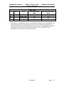
GS ! n
[Name]
[Format]
[E]
Select character size
n
ASCII
GS
!
n
Hex
1D
21
n
Decimal
29
33
[Range]
0 n 255
(1 vertical number of times 8, 1 horizontal number of times 8 )
[Description] Selects the character height using bits 0 to 2 and selects the character
width using bits 4 to 7, as follows:
Character Width Selection
Hex
Decimal
Width
00
0
1 (normal)
10
16
2 (double-width)
20
32
3
30
48
4
40
64
5
50
80
6
60
96
7
70
112
8
Hex
00
01
02
03
04
05
06
07
09/26/2000
Character Height Selection
Decimal
Height
0
1 (normal)
1
2 (double-height)
2
3
3
4
4
5
5
6
6
7
7
8
Page 5 - 17
Software Commands
Model 181 Series 180
Programmer’s Guide
TransAct Technologies
GS B n
[Name]
[Format]
[E]
Turn white/black reverse printing mode on/off
n
ASCII
GS
B
n
Hex
1D
42
n
Decimal
29
66
[Range]
0 n 255
[Description] Turns on or off white/black reverse printing mode.
When the LSB is 0, white/black reverse mode is turned off.
When the LSB is 1, white/black reverse mode is turned on.
DC2
[Name]
[Format]
[A]
Select double-wide characters
ASCII
DC2
Hex
12
Decimal
18
[Description] Prints double-wide characters. The printer is reset to single-wide mode
after a line has been printed or a Clear Printer (10) command is received.
DC3
[Name]
[Format]
[A]
Select single-wide characters
ASCII
DC3
Hex
13
Decimal
19
[Description] Prints single-wide characters
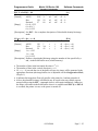
ESC SYN n
[A]
[Name]
Select pitch (column width)
n
[Format]
ASCII
ESC
SYN
n
Hex
1B
16
n
Decimal
27
22
[Range]
0 = Standard (44 col/15.61 CPI)
1 = Compressed (57 col/20.3 CPI)
n=0
[Default]
[Description] Selects the character pitch for a print line. See “Appendix B” for a
description of both pitches.
Page 5 - 18
09/26/2000
Programmer’s Guide
Model 181 Series 180
Software Commands
TransAct Technologies
Panel Button Commands
ESC c 5 n
[Name]
[Format]
[EAB]
Enable/disable panel buttons
n
ASCII
ESC c
5
n
Hex
1B
63
35
n
Decimal
27
99
53
[Range]
0 n 255
[Description] Enables or disables the panel buttons.
When the LSB is 0, the panel buttons are enabled.
When the LSB is 1, the panel buttons are disabled.
In Epson TM-T8x emulation mode, the ESC @ command will re-enable the panel
buttons.
Paper Sensor Commands
ESC c 3 n
[Name]
[Format]
[E]
Select paper sensor(s) to output paper end signals
n
ASCII
ESC c
3
n
Hex
1B
63
33
n
Decimal
27
99
51
[Range]
0 n 255
[Description] Selects the paper sensor(s) to output paper end signals. This command is
available only with a parallel interface and is ignored with a serial
interface.
Each bit of n is used as follows:
Bit
0
1
2
3
4-7
Off/On
Off
On
Off
On
Off
On
Off
On
-
Hex
00
01
00
02
00
04
00
08
-
Decimal
0
1
0
2
0
4
0
8
-
Function
Ignored.
Ignored.
Ignored.
Ignored.
Paper roll end sensor disabled.
Paper roll end sensor enabled.
Paper roll end sensor disabled.
Paper roll end sensor enabled.
Undefined.
09/26/2000
Page 5 - 19
Software Commands
Model 181 Series 180
Programmer’s Guide
TransAct Technologies
ESC c 4 n
[Name]
[Format]
[E]
Select paper sensor(s) to stop printing
n
ASCII
ESC
c
4
n
Hex
1B
63
34
n
Decimal
27
99
52
[Range]
0 n 255
[Description] This command is not supported and is ignored if received.
Print Position Commands
ESC $ nL nH
[EA]
[Name]
Set absolute print position
nL
nH
[Format]
ASCII
ESC
$
nL
nH
Hex
1B
24
nL
nH
Decimal
27
36
[Range]
0 nL 255
0 nH 255
[Description] Sets the print starting position from the beginning of the line.
[Epson TM-T8x]
The distance in dots from the beginning of the line to the print position is [(nL + nH ×
256) × (horizontal motion unit)].
[Axiohm 7193]
If non-graphics follow this command, the distance in dots from the beginning of the
line to the print position is [(nL + nH × 256) × (horizontal motion unit)].
If graphics follow this command, the distance in dots from the beginning of the line to
the print position is [(nL + nH × 256) × (horizontal motion unit)] / 2.
ESC \ nL nH
[EA]
[Name]
Set relative print position
nL
nH
[Format]
ASCII
ESC \
nL
nH
Hex
1B
5C
nL
nH
Decimal
27
92
[Range]
0 nL 255
0 nH 255
[Description] Sets the print starting position based on the current position.
This command sets the distance from the current position to [(nL + nH × 256) ×
horizontal unit].
Page 5 - 20
09/26/2000
Programmer’s Guide
Model 181 Series 180
Software Commands
TransAct Technologies
ESC a n
[Name]
[Format]
[EA]
Select justification
n
ASCII
ESC
a
n
Hex
1B
61
n
Decimal
27
97
[Range]
0 n 2, 48 n 50
[Description] Aligns all the data in one line to the specified position n selects the
justification as follows:
n
0, 48
1, 49
2, 50
Justification
Left Justification
Centering
Right Justification
HT
[Name]
[Format]
[EAB]
Horizontal tab
ASCII
HT
Hex
09
Decimal
9
[Description] Moves the print position to the next horizontal tab position if that position
exists.
ESC D n1 ... nk NUL
[Name]
Set horizontal tab positions
n1 ... nk
[Format]
ASCII
ESC
D
n1 ... nk
Hex
1B
44
n1 ... nk
Decimal
27
68
[Range]
1 n 255
0 k 32
[Default]
Every 8 characters for the 13×24 font.
[Epson TM -300] n = column number-1
[Description] Sets horizontal tab positions.
[EAB]
NUL
00
0
n specifies the column number for setting a horizontal tab position from the beginning
of the line.
k indicates the total number of horizontal tab positions to be set.
Epson and Axiohm emulation modes treat tab positions differently depending upon
factors such as character pitch, expansion and rotation.
09/26/2000
Page 5 - 21
Software Commands
Model 181 Series 180
Programmer’s Guide
TransAct Technologies
GS L nL nH
[Name]
Set left margin
nL
[Format]
ASCII
GS
L
nL
Hex
1D
4C
nL
Decimal
29
76
[Range]
0 nL 255
0 nH 255
[Description] Sets the left margin using nL and nH.
[E]
nH
nH
nH
The left margin is set to [(nL + nH 256) horizontal motion unit)] from the
beginning of the line.
GS W nL nH
[E]
[Name]
Set printing area width
nL
nH
[Format]
ASCII
GS
W
nL
nH
Hex
ID
57
nL
nH
Decimal
29
87
[Range]
0 nL 255
0 nH 255
[Description] The printing area width is set to [(nL + nH 256) horizontal motion
unit)] from the left margin.
ESC DC4 n
[Name]
[Format]
[A]
Set column
n
ASCII
ESC
DC4
n
Hex
1B
14
n
Decimal
27
20
[Range]
1 n 44 (Standard Pitch)
1 n 57 (Compressed Pitch)
if n is set to 0, 1 is assumed.
[Description] Prints the first character of the next print line in column n. It must be sent
for each line not printed at column one. The value of n is set to one after
each line.
Page 5 - 22
09/26/2000
Programmer’s Guide
Model 181 Series 180
Software Commands
TransAct Technologies
Bit-Image Commands
ESC m nL nH d1 ... dk
[EAB]
[Name]
Select bit-image mode
m
nL
nH
d1 ... k
[Format]
ASCII
ESC *
m
nL
nH
d1 ... k
Hex
1B
2A
m
nL
nH
d1 ... k
Decimal
27
42
m = 0, 1, 32, 33
[Range]
0 nL 255
0 nH 3
0 d 255
[Epson TM -300] m = 0 or 1 only
[Description] Selects a bit-image mode using m for the number of dots specified by nL
and nH, as follows:
m
0
1
32
33
Mode
8-dot single-density
8-dot double-density
24-dot single-density
24-dot double-density
Vertical Direction
Number
Density
of Dots
(DPI)
8
68
8
68
24
203
24
203
Horizontal Direction
Density
Amount of Data
(DPI)
(k)
102
nL + nH × 256
203
nL + nH × 256
102
(nL + nH × 256) × 3
203
(nL + nH × 256) × 3
The nL and nH indicate the number of dots of the bit image in the horizontal direction.
The number of dots is calculated by nL + nH × 256.
If the bit-image data input exceeds the number of dots to be printed on a line, the
excess data is ignored.
d indicates the bit-image data. Set a corresponding bit to 1 to print a dot or to 0 to not
print a dot.
8-Dot Single-Density Mode representation
MSB
Top of bit-image
d1
d2
d3
d4
....
....
....
....
....
dn
dn
LSB
09/26/2000
Page 5 - 23
Software Commands
Model 181 Series 180
Programmer’s Guide
TransAct Technologies
24-Dot Single-Density Mode representation
Top of bit-image
d1
d4
d7
d2
d5
...
d3
d6
...
....
MSB
dn
dn
LSB
ESC K nL nH d1 ... dk
[A]
[Name]
Select 8-dot single-density bit-image mode
nL
nH
d1 ... k
[Format]
ASCII
ESC K
nL
nH
d1 ... k
Hex
1B
4B
nL
nH
d1 ... k
Decimal
27
75
[Range]
0 nL 255
0 nH 3
0 d 255
[Epson TM -300] Print and reverse feed not supported.
[Description] See ESC * for a complete description of 8-dot single-density bit-image
mode.
ESC L nL nH d1 ... dk
[A]
[Name]
Select 8-dot double-density bit-image mode
nL
nH
d1 ... k
[Format]
ASCII
ESC L
nL
nH
d1 ... k
Hex
1B
4C
nL
nH
d1 ... k
Decimal
27
76
[Range]
0 nL 255
0 nH 3
0 d 255
[Description] See ESC * for a complete description of 8-dot double-density bit-image
mode.
Page 5 - 24
09/26/2000
Programmer’s Guide
Model 181 Series 180
Software Commands
TransAct Technologies
ESC Y nL nH d1 ... dk
[A]
[Name]
Select 8-dot double-density bit-image mode
nL
nH
d1 ... k
[Format]
ASCII
ESC Y
nL
nH
d1 ... k
Hex
1B
59
nL
nH
d1 ... k
Decimal
27
89
[Range]
0 nL 255
0 nH 3
0 d 255
[Description] See ESC * for a complete description of 8-dot double-density bit-image
mode.
GS x y d1 ... d(x × y × 8)
[EA]
[Name]
Define downloaded bit-image in the RAM buffer
x
y
d1 ... d(x y 8)
[Format]
ASCII
GS
*
x
y
d1 ... d(x y 8)
Hex
1D
2A
x
y
d1 ... d(x y 8)
Decimal
29
42
[Range]
1 x 255
1 y 48
0 d 255
[Description] Defines a downloaded bit-image using the number of dots specified by x
and y in the RAM buffer area (volatile memory).
The number of dots in the horizontal direction is x 8.
The number of dots in the vertical direction is y 8.
If ( x × y × 8) exceeds the size of the buffer in bytes, the image will be truncated in the
appropriate directions (the image buffer size is adjustable via the Configuration Mode,
Chapter 1).
d indicates bit-image data. Data (d) specifies a bit printed to 1 and not printed to 0.
After a downloaded bit-image is defined it may be saved to the non-volatile eeprom
storage buffer using the ESC ‘ command where it will remain indefinitely. Otherwise,
the image will remain in the RAM buffer where it is available until ESC @ or ESC &
is executed; the printer is reset; or the power is turned off.
09/26/2000
Page 5 - 25
Software Commands
Model 181 Series 180
Programmer’s Guide
TransAct Technologies
A representation of the format of a downloaded bit-image is depicted below:
Column
one
d1
dy
+1
d2
dy
+2
....
....
...
...
....
MSB
....
....
....
dn
....
LSB
d(xy8)
dy
GS / m
[Name]
[Format]
[EAI]
Print downloaded/stored bit-image
m
ASCII
GS
/
m
Hex
1D
2F
m
Decimal
29
47
[Description] Prints a downloaded or stored bit-image using the mode specified by m. m
selects a mode from the table below:
m
0-2
3-5
6
Off/On
*
On
Hex
*
40
Decimal
*
64
7
Off
-
00
-
00
-
Page 5 - 26
Function
See Mode Table below
Ignored.
Print image in user defined non-volatile
eeprom storage.
Print image in user defined RAM storage.
Ignored.
09/26/2000
Programmer’s Guide
Model 181 Series 180
Software Commands
TransAct Technologies
Hex
00
01
02
03
Decimal
0
1
2
3
Mode
Normal
Double-width
Double-height
Quadruple
Mode Table
Vertical Dot Density
(DPI)
203
203
101
101
Horizontal Dot Density
(DPI)
203
101
203
101
If the printer is commanded to print a user defined bit-image from the RAM buffer and
that image does not exist, the printer will check the non-volatile eeprom buffer for a
saved user defined bit-image and print that image if it exists. Existing applications not
programmed to make use of the eeprom storage buffer can use this fact to take
advantage of non-volatile user defined bit-images.
09/26/2000
Page 5 - 27
Software Commands
Model 181 Series 180
Programmer’s Guide
TransAct Technologies
Status Commands
GS a n
[Name]
[Format]
[E]
Enable/Disable Automatic Status Back (ASB)
n
ASCII
GS
a
n
Hex
1D
61
n
Decimal
29
97
[Range]
0 n 255
n=0
[Default]
[Description] Enables or disables ASB. ASB is enabled if any item is selected. The
printer automatically generates a 4-byte status message whenever the
status changes. Multiple status items can be selected. When n = 0, ASB is
disabled. If ASB is enabled when the printer is disabled by the ESC =
command, the printer transmits a 4-byte status message whenever the
status changes. The status items are selected using n as follows:
Bit
0
1
2
3
4-7
Off/On
Off
On
Off
On
Off
On
Off
On
-
Hex
00
01
00
02
00
04
00
08
-
Decimal
0
1
0
2
0
4
0
8
-
First byte (Printer information)
Bit Off/On Hex Decimal
0
Off
00
0
1
Off
00
0
2
Off
00
0
On
04
4
3
Off
00
0
On
08
8
4
On
10
16
5
Off
00
0
On
20
32
6
Off
00
0
On
40
64
7
Off
00
0
Function
Drawer kick-out connector status disabled.
Drawer kick-out connector status enabled.
On-line/off-line status disabled.
On-line/off-line status enabled.
Error status disabled.
Error status enabled.
Paper roll sensor status disabled.
Paper roll sensor status enabled.
Undefined.
Status for ASB
Not used. Fixed to Off.
Not used. Fixed to Off.
Drawer 1 or 2 kick-out connector status is LOW**.
Drawer 1 or 2 kick-out connector status is HIGH**.
On-Line.
Off-Line.
Not used. Fixed to On.
Cover Closed.
Cover Opened.
Paper is not being fed by the paper feed button.
Paper is being fed by the paper feed button.
Not used. Fixed to Off.
** See Appendix X for Cash drawer connector information.
Page 5 - 28
09/26/2000
Programmer’s Guide
Model 181 Series 180
Software Commands
TransAct Technologies
Second Byte (error information)
Bit Off/On Hex Decimal
0-2 3
Off
00
0
On
08
8
4
Off
00
0
5
Off
00
0
On
20
32
6
Off
00
0
On
40
64
7
Off
00
0
Status for ASB
Undefined.
No auto-cutter error.
Auto-cutter error occurred.
Not used. Fixed to Off.
No unrecoverable error.
Unrecoverable error occurred.
No automatically recoverable error occurred.
Automatically recoverable error occurred.
Not used. Fixed to Off.
Third byte (paper sensor information)
Bit Off/On Hex Decimal Status for ASB
0,1 Not used. Fixed to Off.
2,3 Off
00
0
Paper roll sensor: paper present.
On
0C
12
Paper roll sensor: paper NOT present.
4
Off
00
0
Not used. Fixed to Off.
5,6 Undefined.
7
Off
00
0
Not used. Fixed to Off.
Fourth byte (paper sensor information)
Bit Off/On Hex Decimal Status for ASB
0-3 Undefined.
4
Off
00
0
Not used. Fixed to Off.
5,6
Undefined.
7
Off
00
0
Not used. Fixed to Off.
GS r n
[Name]
[Format]
[E]
Transmit status
n
ASCII
GS
r
n
Hex
1D
72
n
Decimal
29
114
[Range]
1 n 2, 49 n 50
[Description] Transmits the status specified by n as follows:
n
1, 49
2, 50
Function
Transmits paper sensor status
Transmits drawer kick-out connector status
09/26/2000
Page 5 - 29
Software Commands
Model 181 Series 180
Programmer’s Guide
TransAct Technologies
Paper sensor status (n = 1 , 49).
Bit Off/On Hex Decimal
0,1 2,3 Off
00
0
On
0C
12
4
Off
00
0
5,6 7
Off
00
0
Status
Not used. Fixed to Off.
Paper roll sensor: paper present.
Paper roll sensor: paper NOT present.
Not used. Fixed to Off.
Undefined.
Not used. Fixed to Off.
Drawer kick-out connector status (n = 2, 50).
Bit Off/On Hex Decimal Status
0
Off
00
0
Drawer 1 or 2 connector status is LOW.
On
01
1
Drawer 1 or 2 connector status is HIGH.
1-3 Undefined.
4
Off
00
0
Not used. Fixed to Off.
5,6
Undefined.
7
Off
00
0
Not used. Fixed to Off.
DLE EOT n
[E*]
[Name]
Real-time status transmission
n
[Format]
ASCII
DLE
EOT
n
Hex
10
04
n
Decimal
16
4
n
[Range]
1 4
[Usage]
Epson TM-T8x emulation mode only.
[Description] Transmits the selected printer status specified by n in real time, according
to the following parameters:
n
1
2
3
4
Function
Transmit printer status
Transmit off-line status
Transmit error status
Transmit paper roll sensor status
Page 5 - 30
09/26/2000
Programmer’s Guide
Model 181 Series 180
Software Commands
TransAct Technologies
Printer status (n=1)
Bit Off/On Hex
0
Off
00
1
Off
02
2
Off
00
On
04
3
Off
00
On
08
4
On
10
5,6 7
Off
00
Decimal
0
2
0
4
0
8
16
0
Status
Not used. Fixed to Off.
Not used. Fixed to On.
Drawer 1 or 2 kick-out connector status is LOW**.
Drawer 1 or 2 kick-out connector status is HIGH**.
On-Line.
Off-Line.
Not used. Fixed to On.
Undefined.
Not used. Fixed to Off.
** See Chapter 1 for Cash drawer connector information.
Off-line status (n=2)
Bit Off/On Hex
0
Off
00
1
On
02
2
Off
00
On
04
3
Off
00
On
08
4
On
10
5
Off
00
On
20
6
Off
00
On
40
7
Off
00
Decimal
0
2
0
4
0
8
16
0
32
0
64
0
Status
Not used. Fixed to Off.
Not used. Fixed to On.
Cover is closed.
Cover is open.
Paper is not being fed by the FEED button.
Paper is being fed by the FEED button.
Not used. Fixed to On.
No paper-end stop.
Printing stops due to paper-end.
No error.
Error occurred.
Not used. Fixed to Off.
09/26/2000
Page 5 - 31
Software Commands
Model 181 Series 180
Programmer’s Guide
TransAct Technologies
Error status (n=3)
Bit Off/On Hex
0
Off
00
1
On
02
2
3
Off
00
On
08
4
On
10
5
Off
00
On
20
6
Off
00
On
40
7
Off
00
Decimal
0
2
0
8
16
0
32
0
64
0
Paper roll sensor status (n=4)
Bit Off/On Hex Decimal
0
Off
00
0
1
On
02
2
2, 3 Off
00
0
On
0C
12
4
On
10
16
5, 6 Off
00
0
On
60
96
7
Off
00
0
Status
Not used. Fixed to Off.
Not used. Fixed to On.
Undefined.
No auto-cutter error.
Auto-cutter error occurred.
Not used. Fixed to On.
No unrecoverable error.
Unrecoverable error occurred.
No automatically recoverable error occurred.
Automatically recoverable error occurred.
Not used. Fixed to Off.
Status
Not used. Fixed to Off.
Not used. Fixed to On.
Paper roll near-end sensor: paper adequate.
Paper roll near-end sensor: paper near end.
Not used. Fixed to On.
Paper roll end sensor: paper present.
Paper roll end sensor: paper not present.
Not used. Fixed to Off.
ESC v
[Name]
[Format]
[EB]
Transmit printer status
ASCII
ESC
v
Hex
1B
76
Decimal
27
118
[Epson TM -300] Bit 2 = Paper end
Bit 0,1,3-7 = undefined
[Description] Transmits the status of the paper sensor as 1 byte of data. When the paper
roll end sensor detects a paper-end, the printer goes off line and does not
execute this command until the paper-end condition is corrected.
Bit
0,1
2,3
4
5,6
7
Off/On
Off
On
Off
Off
Page 5 - 32
Hex
00
0C
00
00
Decimal
0
12
0
0
Status
Not used. Fixed to Off.
Paper roll sensor: paper present.
Paper roll sensor: paper NOT present.
Not used. Fixed to Off.
Undefined.
Not used. Fixed to Off.
09/26/2000
Programmer’s Guide
Model 181 Series 180
Software Commands
TransAct Technologies
ESC u n
[Name]
[Format]
[EB]
Transmit peripheral device status
n
ASCII
ESC
u
n
Hex
1B
75
n
Decimal
27
117
n = 0, 48
[Range]
[Usage]
*Epson TM-T8x emulation mode definition.
[Epson TM -300] n= 0, LSB only used.
[Description] Transmits the status of the draw kick-out connector as a byte when n = 0
or 48. This command allows the host to determine the status of a
peripheral device.
Bit
0
1-3
4
5,6
7
Off/On
Off
On
Off
Off
Hex
00
01
00
00
Decimal
0
1
0
0
Status
Drawer 1 or 2 connector status is LOW.**
Drawer 1 or 2 connector status is HIGH.**
Undefined.
Not used. Fixed to Off.
Undefined.
Not used. Fixed to Off.
** See Chapter 1 for Cash drawer connector information.
ESC u n
[Name]
[Format]
[A]
Request alternate status
n
ASCII
ESC
u
n
Hex
1B
75
n
Decimal
27
117
[Range]
See table below.
[Usage]
*Axiohm 7193 emulation mode definition, Parallel printer.
[Description] Sends status data to the host system. This command is available only on
Parallel printers and is intended for situations when the host computer
requires status but is not capable of P1284 bi-directional communications.
When this command is sent to the printer, the printer waits until all the
data in the input buffer has been processed. The PAPER EXHAUST line
then shows the status for the cash drawer or receipt paper as follows:
09/26/2000
Page 5 - 33
Software Commands
Model 181 Series 180
Programmer’s Guide
TransAct Technologies
1
n
00
Function
Drawer 1
01
Drawer 2
02
03
Paper Low (Not
Implemented)
Paper Out
>03
Ignored, No Change
Description
High = Open
Low = Closed or Not Present
High = Open
Low = Closed or Not Present
High = Paper Low
Low = Not Used
High = Paper Out (Default)
Low = Not Used
Printer Does Not Stay BUSY1
PAPER EXHAUST LINE is valid to indicate previously requested status.
ESC u 0
[Name]
[Format]
[A*]
Transmit cash drawer status
ASCII
ESC
u
0
Hex
1B
75
0
Decimal
27
117
0
[Usage]
*Axiohm 7193 mode definition, Serial printer.
[Description] Transmits current status of the cash drawers. One byte is sent to the host
system. If a drawer is not connected, the status will indicate closed.
Bit
0
1
1 Signifies
Drawer 1 Closed
Drawer 2 Closed
ESC v
[Name]
[Format]
0 Signifies
Drawer 1 Open
Drawer 2 Open
[A]
Transmit printer status
ASCII
ESC
v
Hex
1B
76
Decimal
27
118
[Description] Sends one byte of status data to the host system. The printer
will always respond with a NULL character (00 Hex) indicating a no fault
condition. If the printer has one of the error conditions indicated in the
table below, it will go busy and not respond.
Page 5 - 34
09/26/2000
Programmer’s Guide
Model 181 Series 180
Software Commands
TransAct Technologies
Bit
0
1
2
3
4
5
6
7
Status
Receipt Paper
Receipt Cover
Receipt Paper
Knife
Not Used
Printhead
Input Voltage
Not Used
0 Signifies
Present
Closed
Present
OK
OK
OK
Bar Code Commands
GS h n
[Name]
[Format]
[EA]
Set bar code height
ASCII
GS
Hex
1D
Decimal
29
1 n 255
h
68
104
n
n
n
[Range]
[Default]
[Epson TM-T8x]
0.90 inches high
[Axiohm 7193]1.06 inches high
[Description] Sets the height of the bar code.
Bar code height is set to [n/180] inches in Epson emulation mode.
Bar code height is set to [n/152] inches for Axiohm emulation mode.
GS w n
[Name]
[Format]
[EA]
Set bar code width
n
ASCII
GS
w
n
Hex
1D
77
n
Decimal
29
119
[Range]
1n6
n=3
[Default]
[Description] Set the horizontal side of the bar code. n specifies the bar code width as
follows:
09/26/2000
Page 5 - 35
Software Commands
Model 181 Series 180
Programmer’s Guide
TransAct Technologies
n
Module Width (mm)
for Multi-level Bar Code
1
2
3
4
5
6
0.125
0.250
0.375
0.500
0.625
0.750
Binary-level Bar Code
Thin element width (mm)
0.125
0.250
0.375
0.500
0.625
0.750
Thick element width (mm)
0.375
0.625
1.000
1.250
1.625
2.000
Multi-level bar codes are as follows:
UPC-A, UPC-E, JAN13 (EAN 13), JAN 8 (EAN 8), CODE93, CODE128
Binary-level bar codes are as follows:
CODE39, ITF, CODABAR
1
GS k m d1...dk NUL 2 GS k m n d1...dn
[EA]
[Name]
Print bar code
1
m
d1...dk
ASCII
GS
k
NUL
[Format]
m
d1...dk 00
Hex
1D
6B
d1...dk 0
Decimal
29
107 m
2
m
n
d1...dn
ASCII
GS
k
m
n
d1...dn
Hex
1D
6B
n
d1...dn
Decimal
29
107 m
1
[Range]
0 m 6 (k and d depends on the bar code system used)
2
65 m 73 (n and d depends on the bar code system used)
[Description] Selects a bar code system and prints the bar code.
m selects a bar code system as follows:
1
1
1
1
1
1
1
m
0
1
2
3
4
5
6
Bar Code System
UPC-A
UPC-E
JAN13 (EAN 13)
JAN 8 (EAN 8)
CODE39
Number of Characters
11 k 12
11 k 12
12 k 13
7k8
1k
ITF
CODABAR
1 k (even number)
1k
Page 5 - 36
09/26/2000
Remarks
48 d 57
48 d 57
48 d 57
48 d 57
48 d 57, 65 d 90
d = 32, 36, 37, 43, 45, 46,
47
48 d 57
48 d 57, 65 d 68
d = 32, 36, 37, 43, 45, 46,
47, 58
Programmer’s Guide
Model 181 Series 180
Software Commands
TransAct Technologies
2
2
2
2
2
m
65
66
67
68
69
Bar Code System
UPC-A
UPC-E
JAN13 (EAN 13)
JAN 8 (EAN 8)
CODE39
Number of Characters
11 k 12
11 k 12
12 k 13
7k8
1 n 255
2
70
ITF
2
71
CODABAR
1 n 255
(even number)
1 n 255
2
72
73
CODE93
CODE128
1 n 255
2 n 255
2
Remarks
48 d 57
48 d 57
48 d 57
48 d 57
48 d 57, 65 d 90
d = 32, 36, 37, 43, 45, 46,
47
48 d 57
48 d 57, 65 d 68
d = 32, 36, 37, 43, 45, 46,
47, 58
0 d 127
0 d 127
[Description for 1]
d indicates the character code to be printed.
A NULL (00 Hex) character ends the bar code definition.
[Description for 2]
n indicates the number of bytes of bar code data to be processed immediately following
n.
d indicates the character code to be printed.
The following apply to both GS k m d1...dk NUL and GS k m n d1...dn:
If the horizontal width exceeds the printing area, the printer only feeds the paper.
These commands feed as much paper as necessary to print the bar code according to
the GS h command.
These commands are enabled only when no data exists in the print buffer. When data
does exist in the print buffer, the printer processes the data following m as normal data.
After printing a bar code, the print position is set the beginning of the line.
These commands are not effected by print modes (emphasized, underline, character
size...), except for upside-down mode.
09/26/2000
Page 5 - 37
Software Commands
Model 181 Series 180
Programmer’s Guide
TransAct Technologies
GS H n
[Name]
[Format]
[EA]
Select printing position of HRI characters
n
ASCII
GS
H
n
Hex
1D
48
n
Decimal
29
72
[Range]
0 n 3, 48 n 51
[Description] Selects the printing position of HRI characters when printing a bar code.
n selects the printing position as follows:
n
0, 48
1, 49
2, 50
3, 51
Printing position
Not printed.
Above bar code.
Below bar code.
Both above and below the bar code.
HRI indicates Human Readable Interpretation.
GS f n
[Name]
[Format]
[E]
Select font for Human Readable Interpretation (HRI) characters
n
ASCII
GS
f
n
Hex
1D
66
n
Decimal
29
102
n = 0, 1, 48, 49
[Range]
[Description] Selects a font for the HRI characters used when printing a bar code. n
selects a font from the following table:
n
0, 48
1, 49
Font
Font A (13 24)
Font B (10 24)
Macro Function Commands
GS :
[Name]
[Format]
[E]
Start/end macro definition
ASCII
GS
:
Hex
1D
3A
Decimal
29
58
[Description] Starts or ends macro definition.
Macro definition starts when this command is received during normal operation and
ends when it is received during the macro definition.
The macro definition can contain up to 2048 bytes. If the definition exceeds this
value, the excess data is not stored.
Page 5 - 38
09/26/2000
Programmer’s Guide
Model 181 Series 180
Software Commands
TransAct Technologies
GS ^ r t m
[Name]
[Format]
[EI]
Execute macro
ASCII
GS
Hex
1D
Decimal
29
[Range]
0 r 255
0 t 255
m = See below
[Description] Executes a macro.
^
5E
94
r
r
r
t
t
t
m
m
m
r specifies the number of times to execute the macro. When Bit 1 of m is set, r is
ignored and the macro is executed infinitely.
t specifies the waiting time for executing the macro; it is t 100 msec for every macro
execution.
m specifies macro executing mode.
When the LSB of m = 0:
The macro executes r times continuously with interval specified by t.
When the LSB of m = 1:
After waiting for the period specified by t, the printer remains idle and waits for the
FEED button to be pressed. After the button is pressed, the printer executes the macro
once. The printer repeats this operation r times.
When Bit 5 of m is set, the current macro definition is saved into the printers nonvolatile eeprom memory as a startup macro without executing it. This macro
definition will be executed upon power-up using the parameters specified by this
command. If the printer is powered-up into self-test mode, the macro definition will
not be executed. A saved macro definition can be deleted with the GS _ command.
NOTE: Creating a startup macro reduces the eeprom storage area by 2048 bytes for
the duration of that macro and erases the previous contents of the eeprom buffer. Any
user defined characters sets or bit-images must be redefined after creating a startup
macro.
Definition of Mode byte m:
Bit Off/On Hex Decimal
0
Off
00
0
On
1-4 5
On
01
20
1
32
6
On
40
64
7
-
-
-
Function
Macro executes r times continuously with the interval
specified by t.
FEED button controlled operation with time interval t.
Undefined
Value given by r is ignored and macro is run
infinitely.
Save startup macro definition to eeprom memory
without executing.
Undefined.
09/26/2000
Page 5 - 39
Software Commands
Model 181 Series 180
Programmer’s Guide
TransAct Technologies
GS _ _
[Name]
[Format]
[I]
Delete startup macro definition
ASCII
GS
_
Hex
1D
5F
Decimal
29
95
[Description] Deletes a startup macro definition previously created by the GS ^
command.
If a startup macro was not previously defined, this command is ignored.
If a startup macro was previously defined, the macro definition is deleted and the space
it occupied is returned to the eeprom buffer.
NOTE: Any user defined character sets or bit-images will be erased and must be
redefined after deleting the startup macro.
Mechanism Control Commands
1
GS V m
[Name]
[Format]
2
GS V m n
[E]
Select cut mode and cut paper
1
m
ASCII
GS
V
m
Hex
1D
56
m
Decimal
29
86
2
m
n
ASCII
GS
V
m
n
Hex
1D
56
m
n
Decimal
29
86
1
m = 1, 49
[Range]
2
m = 65, 66, 0 n 255
[Description] Selects a mode for cutting paper and executes paper cutting. The value of
m selects the mode as follows:
m
1, 49
65, 66
Print mode
Partial cut
Feeds paper (cutting position + (n (vertical motion unit)]), and
performs a partial cut.
ESC i
[Name]
[Format]
[EA]
Partial Knife Cut
ASCII
ESC
i
Hex
1B
69
Decimal
27
105
[Description] Performs a partial knife cut.
Page 5 - 40
09/26/2000
Programmer’s Guide
Model 181 Series 180
Software Commands
TransAct Technologies
EM
[Name]
[Format]
[EA]
SUB
[Name]
[Format]
[A]
Full knife cut
ASCII
EM
Hex
19
Decimal
25
[Description] This command is implemented the same as partial knife cut, ESC i.
Partial knife cut
ASCII
SUB
Hex
1A
Decimal
26
[Description] Performs a partial knife cut.
Miscellaneous Commands
GS P x y
[Name]
[Format]
[Range]
[E]
Set horizontal and vertical motion units
x
ASCII
GS
P
x
Hex
1D
50
x
Decimal
29
80
0 x 255
0 y 255
y
y
y
[Default]
x = 180, y = 360
[Epson TM-T8x]
[Axiohm 7193]x = 152, y = 152
[Description] Sets the horizontal and vertical motion units to 1/x inch and 1/y inches,
respectively. When x and y are set to 0, the default setting of each value is
used (see defaults above).
ESC @
[Name]
[Format]
[EB]
Initialize printer
ASCII
ESC
@
Hex
1B
40
Decimal
27
64
[Description] Clears the data in the print buffer and resets the printer to the mode that
was in effect when the power was turned on.
DLE
[Name]
[Format]
[Usage]
[A*]
Clear printer
ASCII
DLE
Hex
10
Decimal
16
*Axiohm 7193 emulation mode only.
09/26/2000
Page 5 - 41
Software Commands
Model 181 Series 180
Programmer’s Guide
TransAct Technologies
[Description] Clears the print line buffer without printing and sets the printer to
following condition:
Double-Wide (12 dec) command is canceled.
Line Spacing, Pitch, and User-Defined Character Sets and bit-images in RAM are
unaffected.
Single-Wide, Single-High, Non-Rotated, and Left-Aligned characters are set.
Printer is restarted and error status is cleared in a fault condition.
Returns paper exhaust to the paper status if an alternate status has been requested using
the ESC u command. (Parallel interface only)
GS I n
[Name]
[Format]
[E]
Transmit printer ID
n
ASCII
GS
I
n
Hex
1D
49
n
Decimal
29
73
[Range]
1 n 3, 49 n 51
[Description] Transmits the printer ID specified by n as follows:
n
1, 49
Printer ID
Printer model ID
2, 50
3, 51
Type ID
ROM version ID
n = 2, Type ID
Bit
Off/On
0
Off
1
On
2, 3
4
Off
5, 6
7
Off
Hex
00
02
00
00
Specification
ID (hex)
Epson TM-T88/T88P
20
Epson TM-T85
08
Axiohm 7193
71
See Table below.
not implemented, returns zero.
Decimal
0
2
0
0
Function
Not used. Fixed to Off.
Auto-cutter equipped.
Undefined.
Not used. Fixed to Off.
Undefined.
Not used. Fixed to Off.
ESC p m t1 t2
[EAB]
[Name]
Generate pulse
m
t1
t2
[Format]
ASCII
ESC p
m
t1
t2
Hex
1B
70
tl
t2
Decimal
27
112 m
m = 0, 1, 48, 49
[Range]
0 t1 255, 0 t2 255
[Epson TM -300] m= 0 or 1 only.
[Description] Outputs the pulse specified by t1 and t2 to connector pin m as follows:
Pulse ON time = (t1 * 2ms) , Pulse OFF time = (t2 * 2ms)
Page 5 - 42
09/26/2000
Programmer’s Guide
Model 181 Series 180
Software Commands
TransAct Technologies
m
0, 48
1, 49
Connector pin
Drawer 1 kick-out connector pin 5.
Drawer 1 kick-out connector pin 2 (J9 2-3)
** See Appendix X for Cash drawer connector information.
*B
m
0
1
Connector pin
Drawer 1 kick-out connector pin 2.
Drawer 1 kick-out connector pin 5.
ESC = n
[Name]
[Format]
[EA]
Set peripheral device
n
ASCII
ESC
=
n
Hex
1B
3D
n
Decimal
27
61
[Range]
1 n 255
[Description] Selects device to which host computer sends data, using n as follows:
Bit
0
1-7
Off/On
Off
On
-
Hex
00
01
-
Decimal
0
1
-
Function
Printer disabled.
Printer enabled.
Undefined.
When the printer is disabled, it ignores all received data with the exception of the ESC
=, DLE ENQ 1 and DLE ENQ 2 commands.
If ASB is enabled when the printer is disabled by the ESC = command, the printer
transmits a 4-byte status message whenever the status changes.
DLE ENQ n
[E*]
[Name]
Real-time request to printer
n
[Format]
ASCII
DLE
ENQ
n
Hex
10
05
n
Decimal
16
5
[Range]
1n2
[Usage]
*Epson TM-T8x emulation mode only.
[Description] Responds to a request from the host computer. n specifies the request as
follows:
n
Request
1
Recover from an error and restart printing from the line where the error occurred
2
Recover from an error after clearing the receive and print buffers
When an auto-cutter error occurs, the printer can attempt to recover from the error by
using this command without turning the printer off.
09/26/2000
Page 5 - 43
Software Commands
Model 181 Series 180
Programmer’s Guide
TransAct Technologies
ESC ‘ n
[Name]
[Format]
[I]
Copy user defined storage buffers
n
ASCII
ESC
‘
n
Hex
1B
27
n
Decimal
27
39
[Description] Copies data between user defined RAM buffer and the non-volatile
eeprom buffer.
When the LSB of n is 0,
The content of the user defined ram buffer (containing user defined bit-image or
character set) is copied into the non-volatile eeprom storage buffer. The printer will go
busy and remain in that state momentarily while the write is taking place.
Data in the eeprom storage buffer will remain intact indefinitely or until the data is
rewritten with the ESC ‘ command.
When the LSB of n is 1,
The content of the non-volatile eeprom storage buffer (containing user defined bitimage or character set) is copied into the user defined ram buffer.
Data in the RAM storage buffer will remain intact until it is cleared with the ESC @
command or the printer is powered off.
User defined bit-images or character sets stored in the RAM or non-volatile eeprom
buffer can be accessed with the GS / and ESC % commands.
GS E n
[Name]
[Format]
[E*]
Set head energizing time
ASCII
GS
E
Hex
10
45
Decimal
29
69
[Range]
0 n 255
[Usage]
*Epson TM-T8x emulation mode only.
[Description] LSB = 1 normal print mode is selected.
LSB = 0 copy print mode is selected.
Page 5 - 44
09/26/2000
n
n
n
Programmer’s Guide
Model 181 Series 180
Operator Controls
TransAct Technologies
CHAPTER 4
Operator Panel Controls and Switches
Operator Controls consist of one push button and one LED. The location and
functionality of these controls are as follows:
LED
Paper Feed Button
Front of Printer
PAPER FEED BUTTON
The small circular button located on the front of the printer, has several
functions depending on the state of the printer. When the button is pressed, the functions
of the Line Feed button are as follows:
When the printer is in the normal operational state and the panel button is
depressed for a short duration the printer will feed the paper to a point exposing the last
printed line to the user; further depression of the button will result in the activation of the
4 inch/second slew mode in the printer until the button is released.
If the button is depressed during the printer reset cycle its operation varies,
depending on what operating mode you wish to enter. Reference the manual section on
Self -test, or configuring the printer for more details.
POWER/ERROR LED
The power/error LED located above the paper feed button, indicates a
power on state during normal operation. The led will flash when the printer enters any
error state. See Appendix B for the printer flash code definition.
09/26/2000
Page 6 - 1
Operator Controls
Model 181 Series 180
Programmer’s Guide
TransAct Technologies
PRINTER STATE CONTROL SWITCHES
The Model 181 printer monitors the state of the printer based on the position
of several switches housed in the mechanism. The switches monitor the printer with
respect to the availability of paper, the position of the cover and the position of the cutter
mechanism.
Paper Out
Switch
Front Cover
Cover Open
Switch
Cutter Position
Switch
Rear View of Receipt Housing
Paper Out switch:
Mechanical switch used to indicate the presence of paper.
Cover Open switch:
Mechanical switch used to indicate a closed or opened cover.
Cutter position switch: Mechanical switch used to indicate proper homing of the cutter
mechanism.
Page 6 - 2
09/26/2000
Programmer’s Guide
Model 181 Series 180
Trouble Shooting
TransAct Technologies
Chapter 5
Trouble Shooting
HEXADECIMAL DUMP
This feature allows experienced users to see exactly what data is being received by
the printer. This can be useful in finding software problems. When you turn on the
hex dump function, the printer prints all commands and other data in hexadecimal
format along with a guide section to help you find specific commands.
To use the hex dump feature, follow these steps:
1. Enter the printer’s Remote Configuration and turn the Hexdump option ON. See
Chapter 1 for information on using the Remote Configuration.
2. Upon exiting the Remote Configuration or subsequently powering the unit on/off,
the printer will print the following:
HEXADECIMAL DUMP
3. Run any software program that sends data to the printer. The printer prints all the
codes it receives in a two-column format. The first column contains the
hexadecimal codes and the second column gives the ASCII characters that
correspond to the codes.
HEXADECIMAL DUMP
1B 21 00 1B 26 02 40 40 .!..&.@@
1B 25 01 1B 63 34 00 1B .%..c4..
41 42 43 44 45 46 47 48 ABCDEFGH
A period (.) is printed for each code that has no ASCII equivalent.
During the hex dump all commands except DLE EOT and DLE ENQ are
disabled.
4. The printer will remain in this state until the Hexdump mode is turned off in the
Remote Configuration.
09/26/2000
Page 7 - 1
Programmer’s Guide
Model 181 Series 180
Communications
TransAct Technologies
Appendix A
Communications
OVERVIEW
In order for a receipt to be printed, a printer must be able to accept a data stream
containing characters and commands that the host computer wished the printer to
print. This chapter describes the various interfaces to allow this transmission of
data.
INTERFACES
In order for the printer to communicate with the host, a communication link must
be established. The Model 181 supports the following three communication
interfaces:
RS-232C Interface
Parallel Interface
USB
Each of these has a protocol associated with it that the host must understand and
adhere to. Only when the interface parameters are matched and the proper
protocol is used will the host and the printer be able to communicate. See the
respective sections in this chapter for a description of the protocol associated with
each type of interface.
RS-232C INTERFACE
The RS-232C interface uses either RTS/CTS, DTR/DSR or XON/XOFF
protocol. For RTS/CTS, changes in the RTS/CTS signal coordinates the
information flow. For DTR/DSR, changes in the DTR/DSR signal coordinates the
information flow. For XON/XOFF, data characters transmitted between the Host
computer control communication data flow.
The RS-232C version of the Model 181 offers the standard communications
options which are configured in the non-volatile eeprom memory.
RTS/CTS PROTOCOL
The RTS signal is used to control data transmission to the printer. It is driven
High when the printer is ready to receive data and driven low when it cannot
accept any more data. The host will transmit data to the printer when it
recognizes the state of the printer RTS signal is high.
09/26/2000
Page 8 - 1
Communications
Model 181 Series 180
Programmer’s Guide
TransAct Technologies________________________________
DTR/DSR PROTOCOL
The DTR signal is used to control data transmission to the printer. It is driven
High when the printer is ready to receive data and driven low when it cannot
accept any more data. The host will transmit data to the printer when it
recognizes the state of the printers DTR signal is high.
XON/XOFF PROTOCOL
ASCII characters coordinate the information transfer between the printer and the
host system. The printer sends an ASCII DC1(11Hex,XON) character when it is
ready to receive data and it sends an ASCII DC3(13Hex,XOFF) character when
it cannot accept any more data. The host system must monitor the communication
link in order to send data at the appropriate times.
RS-232C TECHNICAL SPECIFICATIONS
This section describes the pin settings for the connectors and the RS-232C
interface parameters.
CONNECTORS
The following table shows the RS-232C communication connector and pin
assignments. The connector is a 9-pin male D-shell connector and is located in
the hollow cavity under the printer.
Pin #
Signal Name
Signal Function
1
NOT USED
2
Received line Signal
Detector
Serial Receive
3
4
5
6
7
8
9
Serial Transmit
Data Terminal Ready
Ground
Data Set Ready
Request to Send
Clear to Send
Ring Indicator
Page 8 - 2
input signal to receive data from the host
system
output signal sending data to the host system
output signal to float control the host
Logic Ground
input signal to float control the printer
output signal to float control the host.
input signal to float control the printer
NOT USED
09/26/2000
PC Host Cross
Connect Pin #
3 Tx
2 Rx
6 DSR
5 GND
4 DTR
7 CTS
6 RTD
Programmer’s Guide
Model 181 Series 180
Communications
TransAct Technologies
PARALLEL INTERFACE
PARALLEL INTERFACE SPECIFICATION (P1284)
Parallel Protocol
The Model 82 uses a standard PC-compatible parallel interface. The following
illustration shows the timing diagram for the interface protocol.
Compatibility Mode:
Busy
Acknowledge(L) pin 10
.5uS
Strobe
Data(pins 9-2)
Ts
.5uS
Th
Th = Ts = .5uSec min.
1. The Host places its data on the data lines.
2. The host strobes the data into the printer latch using Strobe(L)
3. The printer Goes Busy(H) until the printer is ready to receive the next byte.
4. The printer acknowledges receipt of the data byte by Pulsing ACK(L).
5. The printer removes Bush(H) to allow continuation of data flow.
Note:
Definition and timing of the Parallel P1284 interface is beyond the scope of this manual,
for a complete description of this interface refer to the IEEE P1284 Specification.
PARALLEL TECHNICAL SPECIFICATIONS
This table describes the pin settings for the Parallel interface.
Pin 1
Strobe
Clock Data to printer
Pin 2-9
D0-D7
Data
Pin 10
ACK(L)
Printer Accepted Data
Pin 11
Busy
Printer is Busy
Pin 12
PE
Paper Out / Status
Pin 13
SLCT
Printer Selected
Pin 14
AUTOFD
Auto feed paper
Pin 15
ERR(L)
Printer Error
Pin 16
INIT(L)
Initialize the Printer
Pin 17
SLIN
Select Printer
Pin 18-25
GND
Ground
09/26/2000
Host to Printer
Host to Printer
Printer to Host
Printer to Host
Printer to Host
Printer to Host
Host to Printer
Printer to Host
Host to Printer
Host to Printer
Page 8 - 3
Communications
Model 181 Series 180
Programmer’s Guide
TransAct Technologies________________________________
Connectors: USB
The following illustration shows the USB communication connector and pin
assignments. The connector is a USB type B connector and is located in the
hollow cavity under the printer.
Pin #
1
2
3
4
Page 8 - 4
Definition
USVB
-Data
+Data
GND
09/26/2000
Programmer’s Guide
Model 181 Series 180
Error Code Diagnosis
TransAct Technologies
Appendix B
Error Code Diagnosis
Description
The Ithaca Model 181 thermal printer uses a single status LED to display on-line and
error conditions. The tables below describe the types of error conditions possible and the
patterns that the LED will flash for those conditions.
KEY to Graphical representation:
•
= LED IS ON for 0.5 seconds
•
= LED IS ON for 0.1 seconds
= LED IS OFF for 0.5 seconds
_
= LED IS OFF for 0.1 seconds
IN ORDER OR PRECEDENCE
Error Condition Present
Graphical Representation
Verbal Description
QSM RAM ERROR
______•_•_•_•_•_•_•______
(7 quick flashes)
RAM ERROR
______•_•______
(2 quick flashes)
EEPROM VERIFY ERROR
______•_•_•_•_•_•______
(6 quick flashes)
PRINTER NOT CONFIGURED
______•_•_•_•_•______
(5 quick flashes)
THERMAL HEAD OVERHEAT
_•_•_•_•_•_•
(rapid, continuous)
CUTTER ERROR
______•_•_•______
(3 quick flashes)
COVER OPEN
_•_•_•_•_•_•_
(continuous)
PAPER OUT
______••••••______••••••______
(slow, continuous)
09/26/2000
Page 9 - 1
Programmer’s Guide
Model 181 Series 180 Character Code Tables
TransAct Technologies
Appendix C
Character Code Tables
The following pages show the character code tables.
HEX
00
01
02
03
04
05
06
07
08
09
0A
0B
0C
0D
0E
0F
10
11
12
13
14
15
16
17
18
19
1A
1B
1C
1D
1E
1F
Decimal
0
1
2
3
4
5
6
7
8
9
10
11
12
13
14
15
16
17
18
19
20
21
22
23
24
25
26
27
28
29
30
31
ASCII
NULL
SOH
STX
ETX
EOT
ENQ
ACK
BEL
BS
HT
LF
VT
FF
CR
SO
SI
DEL
DC1
DC2
DC3
DC4
NAK
SYN
ETB
CAN
EM
SUB
ESC
FS
GS
RS
US
HEX
20
21
22
23
24
25
26
27
28
29
2A
2B
2C
2D
2E
2F
30
31
32
33
34
35
36
37
38
39
3A
3B
3C
3D
3E
3F
Decimal
32
33
34
35
36
37
38
39
40
42
42
43
44
45
46
47
48
49
50
51
52
53
54
55
56
57
58
59
60
61
62
63
ASCII
SP
!
“
#
$
%
&
(
)
*
+
,
>
/
0
1
2
3
4
5
6
7
8
9
:
;
<
=
>
?
09/26/2000
HEX
40
41
42
43
44
45
46
47
48
49
4A
4B
4C
4D
4E
4F
50
51
52
53
54
55
56
57
58
59
5A
5B
5C
5D
5E
5F
Decimal
64
65
66
67
68
69
70
71
72
73
74
75
76
77
78
79
80
81
82
83
84
85
86
87
88
89
90
91
92
93
94
95
ASCII
@
A
B
C
D
E
F
G
H
I
J
K
L
M
N
O
P
Q
R
S
T
U
V
W
X
Y
Z
[
\
]
^
_
HEX
60
61
62
63
64
65
66
67
68
69
6A
6B
6C
6D
6E
6F
70
71
72
73
74
75
76
77
78
79
7A
7B
7C
7D
7E
7F
Page 10 - 1
Decimal
96
97
98
99
100
101
102
103
104
105
106
107
108
109
110
111
112
113
114
115
116
117
118
119
120
121
122
123
124
125
126
127
ASCII
`
a
b
c
d
e
f
g
h
i
j
k
l
m
n
o
p
q
r
s
t
u
v
w
x
y
z
{
}
(SP)
Character Code Tables
Model 181 Series 180
Programmer’s Guide
TransAct Technologies
HEX
80
81
82
83
84
85
86
87
88
89
8A
8B
8C
8D
8E
8F
90
91
92
93
94
95
96
97
98
99
9A
9B
9C
9D
9E
9F
Decimal
128
129
130
131
132
133
134
135
136
137
138
139
140
141
142
143
144
145
146
147
148
149
150
151
152
153
154
155
156
157
158
159
Decimal ASCII HEX Decimal ASCII HEX Decimal ASCII
•
•
160
á
C0
192
E0
224
•
•
161
í
C1
193
E1
225
•
•
162
ó
C2
194
E2
226
•
•
163
ú
C3
195
E3
227
•
•
164
ñ
C4
196
E4
228
•
•
165
Ñ
C5
197
E5
229
•
•
166
a
C6
198
E6
230
•
•
167
o
C7
199
E7
231
•
•
•
168
C8
200
E8
232
•
•
•
169
C9
201
E9
233
•
•
•
170
CA
202
EA
234
•
•
•
171
CB
203
EB
235
•
•
•
172
CC
204
EC
236
•
•
•
173
CD
205
ED
237
•
•
•
174
CE
206
EE
238
•
•
•
175
CF
207
EF
239
•
•
•
176
D0
208
F0
240
•
•
•
177
D1
209
F1
241
•
•
•
178
D2
210
F2
242
•
•
•
179
D3
211
F3
243
•
•
•
180
D4
212
F4
244
•
•
•
181
D5
213
F5
245
•
•
•
182
D6
214
F6
246
•
•
•
183
D7
215
F7
247
•
•
•
184
D8
216
F8
248
•
•
•
185
D9
217
F9
249
•
•
•
186
DA
218
FA
250
•
•
•
187
DB
219
FB
251
•
•
•
188
DC
220
FC
252
•
•
•
189
DD
221
FD
253
•
•
•
190
DE
222
FE
254
•
•
ƒ
191
DF
223
FF
255
SP
(PC437: U.S.A., Standard Europe)
(International character set: U.S.A.)
Note: The character code tables show only which characters are printed. They do not show the
actual print pattern.
Page 10 - 2
ASCII
ç
ü
é
â
ä
à
å
ç
ê
ë
è
ï
î
ì
Ä
Å
É
æ
Æ
ô
ö
ò
û
ù
ÿ
ö
ü
¢
£
¥
HEX
A0
A1
A2
A3
A4
A5
A6
A7
A8
A9
AA
AB
AC
AD
AE
AF
B0
B1
B2
B3
B4
B5
B6
B7
B8
B9
BA
BB
BC
BD
BE
BF
09/26/2000
Programmer’s Guide
Model 181 Series 180 Character Code Tables
TransAct Technologies
HEX
80
81
82
83
84
85
86
87
88
89
8A
8B
8C
8D
8E
8F
90
91
92
93
94
95
96
97
98
99
9A
9B
9C
9D
9E
9F
Decimal
128
129
130
131
132
133
134
135
136
137
138
139
140
141
142
143
144
145
146
147
148
149
150
151
152
153
154
155
156
157
158
159
ASCII
Ç
ü
é
â
ä
à
å
ç
ê
ë
è
ï
î
ì
Ä
Å
É
æ
Æ
ô
ö
ò
û
ù
ÿ
ö
Ü
ø
£
Ø
×
ƒ
HEX
A0
A1
A2
A3
A4
A5
A6
A7
A8
A9
AA
AB
AC
AD
AE
AF
B0
B1
B2
B3
B4
B5
B6
B7
B8
B9
BA
BB
BC
BD
BE
BF
Decimal ASCII HEX
160
á
C0
161
í
C1
162
ó
C2
163
ú
C3
164
ñ
C4
165
Ñ
C5
166
a
C6
167
o
C7
•
168
C8
169
®
C9
•
170
CA
•
171
CB
•
172
CC
•
173
CD
•
174
CE
•
175
CF
•
176
D0
•
177
D1
•
178
D2
•
179
D3
•
180
D4
181
Á
D5
182
Â
D6
183
À
D7
184
©
D8
•
185
D9
•
186
DA
•
187
DB
•
188
DC
•
189
DD
•
190
DE
•
191
DF
(PC850: Multilingual)
(PC850: Multilingual)
09/26/2000
Decimal
192
193
194
195
196
197
198
199
200
201
202
203
204
205
206
207
208
209
210
211
212
213
214
215
216
217
218
219
220
221
222
223
ASCII
•
•
•
•
•
+
ã
Ã
•
•
•
•
•
•
•
¤
ð
Ð
Ê
Ë
È
i
Í
Î
Ï
•
•
•
•
Ì
•
HEX
E0
E1
E2
E3
E4
E5
E6
E7
E8
E9
EA
EB
EC
ED
EE
EF
F0
F1
F2
F3
F4
F5
F6
F7
F8
F9
FA
FB
FC
FD
FE
FF
Page 10 - 3
Decimal
224
225
226
227
228
229
230
231
232
233
234
235
236
237
238
239
240
241
242
243
244
245
246
247
248
249
250
251
252
253
254
255
ASCII
•
ß
Ô
Ò
Õ
Õ
µ
þ
Þ
Ú
Û
Ù
ý
Ý
—
´
–
•
•
¾
¶
§
•
`
°
¨
·
1
3
2
•
SP
Character Code Tables
Model 181 Series 180
Programmer’s Guide
TransAct Technologies
HEX
80
81
82
83
84
85
86
87
88
89
8A
8B
8C
8D
8E
8F
90
91
92
93
94
95
96
97
98
99
9A
9B
9C
9D
9E
9F
Decimal
128
129
130
131
132
133
134
135
136
137
138
139
140
141
142
143
144
145
146
147
148
149
150
151
152
153
154
155
156
157
158
159
Page 10 - 4
ASCII
Ç
ü
é
â
ä
à
Á
ç
ê
Ê
è
Í
Ô
ì
Ã
Â
É
À
È
ô
õ
ò
Ú
ù
Ì
Õ
Ü
¢
£
Ù
•
HEX
A0
A1
A2
A3
A4
A5
A6
A7
A8
A9
AA
AB
AC
AD
AE
AF
B0
B1
B2
B3
B4
B5
B6
B7
B8
B9
BA
BB
BC
BD
BE
BF
Decimal
160
161
162
163
164
165
166
167
168
169
170
171
172
173
174
175
176
177
178
179
180
181
182
183
184
185
186
187
188
189
190
191
ASCII
á
í
ó
ú
ñ
Ñ
a
o
•
HEX Decimal
C0
192
C1
193
C2
194
C3
195
C4
196
C5
197
C6
198
C7
199
C8
200
C9
201
•
CA
202
•
CB
203
•
CC
204
•
CD
205
•
CE
206
•
CF
207
•
D0
208
•
D1
209
•
D2
210
•
D3
211
•
D4
212
•
D5
213
•
D6
214
•
D7
215
•
D8
216
•
D9
217
•
DA
218
•
DB
219
•
DC
220
•
DD
221
•
DE
222
•
DF
223
(PC860: Portuguese)
09/26/2000
ASCII
•
•
•
•
•
+
•
•
•
•
•
•
•
•
•
•
•
•
•
•
•
•
•
•
•
•
•
•
•
•
•
•
HEX
E0
E1
E2
E3
E4
E5
E6
E7
E8
E9
EA
EB
EC
ED
EE
EF
F0
F1
F2
F3
F4
F5
F6
F7
F8
F9
FA
FB
FC
FD
FE
FF
Decimal
224
225
226
227
228
229
230
231
232
233
234
235
236
237
238
239
240
241
242
243
244
245
246
247
248
249
250
251
252
253
254
255
ASCII
•
ß
•
•
•
•
•
•
•
•
•
•
•
•
•
•
•
•
•
•
°
·
•
•
2
•
SP
Programmer’s Guide
Model 181 Series 180 Character Code Tables
TransAct Technologies
HEX
80
81
82
83
84
85
86
87
88
89
8A
8B
8C
8D
8E
8F
90
91
92
93
94
95
96
97
98
99
9A
9B
9C
9D
9E
9F
Decimal
128
129
130
131
132
133
134
135
136
137
138
139
140
141
142
143
144
145
146
147
148
149
150
151
152
153
154
155
156
157
158
159
ASCII
Ç
ü
é
â
Â
à
¶
ç
ê
ë
è
ï
î
—
À
§
É
È
Ê
ô
Ë
Ï
û
ù
¤
Ô
Ü
¢
£
Ù
Û
ƒ
HEX
A0
A1
A2
A3
A4
A5
A6
A7
A8
A9
AA
AB
AC
AD
AE
AF
B0
B1
B2
B3
B4
B5
B6
B7
B8
B9
BA
BB
BC
BD
BE
BF
Decimal
160
161
162
163
164
165
166
167
168
169
170
171
172
173
174
175
176
177
178
179
180
181
182
183
184
185
186
187
188
189
190
191
ASCII
HEX Decimal
C0
192
´
C1
193
ó
C2
194
ú
C3
195
¨
C4
196
’
C5
197
³
C6
198
¯
C7
199
Î
C8
200
•
C9
201
•
CA
202
•
CB
203
•
CC
204
¾
CD
205
•
CE
206
•
CF
207
•
D0
208
•
D1
209
•
D2
210
•
D3
211
•
D4
212
•
D5
213
•
D6
214
•
D7
215
•
D8
216
•
D9
217
•
DA
218
•
DB
219
•
DC
220
•
DD
221
•
DE
222
•
DF
223
(PC863: Canadian-French)
09/26/2000
ASCII
•
•
•
•
•
+
•
•
•
•
•
•
•
•
•
•
•
•
•
•
•
•
•
•
•
•
•
•
•
•
•
•
HEX
E0
E1
E2
E3
E4
E5
E6
E7
E8
E9
EA
EB
EC
ED
EE
EF
F0
F1
F2
F3
F4
F5
F6
F7
F8
F9
FA
FB
FC
FD
FE
FF
Page 10 - 5
Decimal
224
225
226
227
228
229
230
231
232
233
234
235
236
237
238
239
240
241
242
243
244
245
246
247
248
249
250
251
252
253
254
255
ASCII
•
ß
•
•
•
•
•
•
•
•
•
•
•
•
•
•
•
•
•
•
°
·
•
•
2
•
SP
Character Code Tables
Model 181 Series 180
Programmer’s Guide
TransAct Technologies
HEX
80
81
82
83
84
85
86
87
88
89
8A
8B
8C
8D
8E
8F
90
91
92
93
94
95
96
97
98
99
9A
9B
9C
9D
9E
9F
Decimal
128
129
130
131
132
133
134
135
136
137
138
139
140
141
142
143
144
145
146
147
148
149
150
151
152
153
154
155
156
157
158
159
ASCII
Ç
ü
é
â
ä
à
å
ç
ê
ë
è
ï
î
ì
Ä
Å
É
æ
Æ
ô
ö
ò
û
ù
ÿ
ö
Ü
ø
£
Ø
ƒ
HEX
A0
A1
A2
A3
A4
A5
A6
A7
A8
A9
AA
AB
AC
AD
AE
AF
B0
B1
B2
B3
B4
B5
B6
B7
B8
B9
BA
BB
BC
BD
BE
BF
Decimal
160
161
162
163
164
165
166
167
168
169
170
171
172
173
174
175
176
177
178
179
180
181
182
183
184
185
186
187
188
189
190
191
ASCII
á
í
ó
ú
ñ
Ñ
a
o
•
•
•
•
•
•
•
¤
•
•
•
•
•
•
•
•
•
•
•
•
•
•
•
•
HEX
C0
C1
C2
C3
C4
C5
C6
C7
C8
C9
CA
CB
CC
CD
CE
CF
D0
D1
D2
D3
D4
D5
D6
D7
D8
D9
DA
DB
DC
DD
DE
DF
Decimal
192
193
194
195
196
197
198
199
200
201
202
203
204
205
206
207
208
209
210
211
212
213
214
215
216
217
218
219
220
221
222
223
(PC865: Nordic)
Page 10 - 6
09/26/2000
ASCII
•
•
•
•
•
+
•
•
•
•
•
•
•
•
•
•
•
•
•
•
•
•
•
•
•
•
•
•
•
•
•
•
HEX
E0
E1
E2
E3
E4
E5
E6
E7
E8
E9
EA
EB
EC
ED
EE
EF
F0
F1
F2
F3
F4
F5
F6
F7
F8
F9
FA
FB
FC
FD
FE
FF
Decimal
224
225
226
227
228
229
230
231
232
233
234
235
236
237
238
239
240
241
242
243
244
245
246
247
248
249
250
251
252
253
254
255
ASCII
•
ß
•
•
•
•
•
•
•
•
•
•
•
•
•
•
•
•
•
•
°
·
•
•
2
•
SP
Programmer’s Guide
Model 181 Series 180 Character Code Tables
TransAct Technologies
HEX
80
81
82
83
84
85
86
87
88
89
8A
8B
8C
8D
8E
8F
90
91
92
93
94
95
96
97
98
99
9A
9B
9C
9D
9E
9F
Decimal
128
129
130
131
132
133
134
135
136
137
138
139
140
141
142
143
144
145
146
147
148
149
150
151
152
153
154
155
156
157
158
159
ASCII
SP
SP
SP
SP
SP
SP
SP
SP
SP
SP
SP
SP
SP
SP
SP
SP
SP
SP
SP
SP
SP
SP
SP
SP
SP
SP
SP
SP
SP
SP
SP
SP
HEX
A0
A1
A2
A3
A4
A5
A6
A7
A8
A9
AA
AB
AC
AD
AE
AF
B0
B1
B2
B3
B4
B5
B6
B7
B8
B9
BA
BB
BC
BD
BE
BF
Decimal
160
161
162
163
164
165
166
167
168
169
170
171
172
173
174
175
176
177
178
179
180
181
182
183
184
185
186
187
188
189
190
191
ASCII HEX Decimal
SP
C0
192
SP
C1
193
SP
C2
194
SP
C3
195
SP
C4
196
SP
C5
197
SP
C6
198
SP
C7
199
SP
C8
200
SP
C9
201
SP
CA
202
SP
CB
203
SP
CC
204
SP
CD
205
SP
CE
206
SP
CF
207
SP
D0
208
SP
D1
209
SP
D2
210
SP
D3
211
SP
D4
212
SP
D5
213
SP
D6
214
SP
D7
215
SP
D8
216
SP
D9
217
SP
DA
218
SP
DB
219
SP
DC
220
SP
DD
221
SP
DE
222
SP
DF
223
(Space Page)
09/26/2000
ASCII
SP
SP
SP
SP
SP
SP
SP
SP
SP
SP
SP
SP
SP
SP
SP
SP
SP
SP
SP
SP
SP
SP
SP
SP
SP
SP
SP
SP
SP
SP
SP
SP
HEX
E0
E1
E2
E3
E4
E5
E6
E7
E8
E9
EA
EB
EC
ED
EE
EF
F0
F1
F2
F3
F4
F5
F6
F7
F8
F9
FA
FB
FC
FD
FE
FF
Page 10 - 7
Decimal
224
225
226
227
228
229
230
231
232
233
234
235
236
237
238
239
240
241
242
243
244
245
246
247
248
249
250
251
252
253
254
255
ASCII
SP
SP
SP
SP
SP
SP
SP
SP
SP
SP
SP
SP
SP
SP
SP
SP
SP
SP
SP
SP
SP
SP
SP
SP
SP
SP
SP
SP
SP
SP
SP
SP
Character Code Tables
Model 181 Series 180
Programmer’s Guide
TransAct Technologies
INTERNATIONAL CHARACTER SET
ASCII Code
Country HEX 23
24
DEC 35
36
U.S.A
#
$
France
#
$
Germany
#
$
U.K.
£
$
Denmark I
#
$
Sweden
#
¤
Italy
#
$
Spain
PT
$
Japan
#
$
Norway
#
¤
Denmark II
#
$
Page 10 - 8
40
64
@
à
§
@
@
É
@
@
@
É
É
5B
91
[
°
Ä
[
Æ
Ä
°
i
[
Æ
Æ
5C
92
\
ç
Ö
\
Ø
Ö
\
Ñ
¥
Ø
Ø
09/26/2000
5D
93
]
§
Ü
]
Å
Å
é
¿
]
Å
Å
5E
94
^
^
^
^
^
Ü
^
^
^
Ü
Ü
60
96
`
`
`
`
`
é
ù
`
`
é
é
7B 7C 7D
123 124 125
{
¦
}
é
ù
è
ä
ö
ü
{
¦
}
œ
ø
å
ä
ö
å
à
ò
è
¨
ñ
}
{
¦
}
œ
ø
å
œ
ø
å
7E
126
˜
˜
ß
˜
˜
ü
ì
˜
˜
ü
ü
Programmer’s Guide
Model 181 Series 180
Upgrading/Changing OS
TransAct Technologies
Appendix D
Upgrading/Changing your printer Operating System
The Ithaca Series 180 thermal printer’s operating system is stored on a non-volatile flash
memory chip. The flash chip in your printer can be reprogrammed at any time using
software utilities supplied by TransAct Technologies Incorporated. These utilities give
you the ability to upgrade the capabilities of your printer’s operating system when newer
versions become available, as well as load customized versions of it to meet your specific
needs. All this process requires is that the Series 180 be connected to a host PC and the
appropriate software utility then run; the entire process takes less than 1.5 minutes.
Contact TransAct’s Ithaca facility or visit our web site for more information about
obtaining updates.
You may reach both the Sales and Technical Support Departments
at the following address and telephone or fax numbers:
TransAct Technologies Incorporated
Ithaca Facility
20 Bomax Drive
Ithaca, NY 14850 USA
Telephone
Main fax
Sales fax
Technical Support fax
Web site
(877) 7ithaca or (607) 257-8901
(607) 257-8922
(607) 257-3868
(607) 257-3911
http://www.transact-tech.com
09/26/2000
Page 11 - 1
THIS PAGE INTENTIONALLY
LEFT BLANK
PN: M068227-01
Rev. A
06/09/00