1
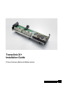
Transclinic Xi+
Installation Guide
PV Array Performance Monitor with Modbus Interface
Revision History
Contact details
Version
Date
Version
1.0
12/2011
First release (Australian
version)
Weidmuller Pty Ltd
43 Huntingwood Drive
Huntingwood
NSW 2148
Australia
Tel.
+61 (0) 2 9671 9999
Fax
+61 (0) 2 9671 9900
E-Mail [email protected]
Internet www.weidmuller.com.au
Contents
Revision History ............................................................................................................................................... 2
Contact details .................................................................................................................................................. 2
Contents ............................................................................................................................. 3
1.
Introduction ........................................................................................................... 5
1.1
General description........................................................................................................................... 5
1.2
Warnings and notices ....................................................................................................................... 6
1.2.1
Qualified personnel .............................................................................................................. 6
1.2.2
Accuracy of the technical documentation ............................................................................ 6
1.2.3
CE Mark ............................................................................................................................... 6
1.2.4
Declaration of Conformity .................................................................................................... 6
1.2.5
Recycling in accordance with WEEE ................................................................................... 7
What we can do for you? ................................................................................................................. 7
What do you have to do?................................................................................................................. 7
1.2.6
Use as intended ................................................................................................................... 7
2.
Installation ............................................................................................................. 8
2.1
General ............................................................................................................................................... 8
2.2
Location ............................................................................................................................................. 8
2.3
Connection diagram.......................................................................................................................... 9
2.4
Power Board Connections ............................................................................................................. 10
2.4.1
PV Array wiring (X1, X2, X4 and Busbars) ........................................................................ 10
String current measurement Inputs (X1 and X4) ........................................................................... 10
String current measurement common output (Busbar) ................................................................. 10
Voltage measurement (X2)............................................................................................................ 11
2.5
3.
CPU Board Connections ................................................................................................................ 11
2.5.1
Power supply (X7).............................................................................................................. 11
2.5.2
Data Communications (X1 and X3) ................................................................................... 11
2.5.3
Opto-coupled Digital inputs (X8) ........................................................................................ 12
2.5.4
Analogue Current/Voltage Inputs (X6 and X5) .................................................................. 12
2.5.5
Digital output (X4) .............................................................................................................. 12
Configuration....................................................................................................... 13
3.1.1
DIP Switches ...................................................................................................................... 13
3.1.2
SW1 – Modbus Address .................................................................................................... 13
3.1.3
SW2 – Data Speed, Parity and Read/Write Lock .............................................................. 13
PV Clinics Installation Manual 21/07/11 01.00
3
4.
Surge protection ................................................................................................. 14
4.1
Best practice for PV Plants ............................................................................................................ 14
4.2
Common mode and differential voltages...................................................................................... 14
4.3
Types of surge protection devices ................................................................................................ 15
4.3.1
DC arresters for PV Array side protection ......................................................................... 15
4.3.2
AC arresters for supply side protection.............................................................................. 15
4.3.3
Surge protection for data communications equipment ......................................................15
5.
Data Communications ........................................................................................ 16
5.1
General ............................................................................................................................................. 16
5.2
RS485 signals .................................................................................................................................. 16
5.2.1
Two wire RS485 ................................................................................................................. 17
5.2.2
Cable Shields ..................................................................................................................... 18
5.2.3
Mixed devices on Transclinics networks............................................................................ 18
5.2.4
Data Cables ....................................................................................................................... 19
5.2.5
Network Topography.......................................................................................................... 19
5.2.6
Termination resistances ..................................................................................................... 20
5.2.7
Addresses, network length and repeaters ......................................................................... 20
5.3
Rules for reliable RS485 networks ................................................................................................ 21
6.
Modbus ................................................................................................................ 22
6.1
General ............................................................................................................................................. 22
6.2
Modbus RTU .................................................................................................................................... 22
6.3
Alternative communications methods .......................................................................................... 23
6.3.1
Modbus TCP (Ethernet) ..................................................................................................... 23
Copper Ethernet Links ................................................................................................................... 23
Fibre-optic Ethernet links ............................................................................................................... 23
6.4
Modbus Maps .................................................................................................................................. 24
6.4.1
Calibration values (Holding Register Values) – for reference only ....................................24
6.5
Measurements (Input Register Values) ......................................................................................... 25
6.6
Register Values ............................................................................................................................... 26
4
6.6.1
Holding Register Values .................................................................................................... 26
6.6.2
Input Register Values......................................................................................................... 26
PV Clinics Installation Manual 21/07/11 01.00 01/12
www.weidmueller.com
1.
Introduction
1.1
General description
Transclinic Xi+ modules provide very detailed monitoring, at the string box, of all the main plant variables,
like string current, voltage and temperature. The current of each string is only one of the principle measures
of the health of a photovoltaic power station; So all Transclinics also allow measurement of the voltage of the
group of strings, the temperature of the equipment and the state of the surge protection, fuses and so on by
means of two analogue inputs and two binary digital inputs. The two analogue signal inputs can be used to
measure almost any variable around the plant. An alarm output is also provided in the form of a solid state
relay.
All data is available via an industry standard RS485 Modbus RTU interface for connection to PV Power plant
SCADA systems or Weidmuller’s Softclinic PV plant monitoring software.
String current measurements are made using precision shunts, which guarantee perfect linearity, greater accuracy and, importantly, measurements that are stable in the long term and free of the drift problems associated with Hall-effect sensors. Designed for mounting in string combiner boxes, the design combines string
currents on-board simplifying the array wiring.
When integrated into your string boxes the system allows a more proactive maintenance by detecting irregularities in electricity generation that normally go un-noticed but decrease the global yield of your investment.
These devices also speed the traditional maintenance of the installation and lower the price of ownership by
immediately alerting your service team to fused/blown surge protection fuses, disconnected cables, poorly
performing panels, and even overheating in the string boxes.
The Transclinic 4xi, 7xi, 8xi and 14xi models can take measurements from 4, 7, 8 or 14 input strings simultaneously, with a maximum input current of 20A or 30A (according to the model). This equipment can work in
ambient temperatures from -20ºC to 70ºC.
1.2
Warnings and notices
NOTICE
This device is intended for use in applications as described in the operating instructions only. Any
other form of usage is not permitted and can lead to accidents or destruction of the device. Using
the device in non-approved applications will lead immediately to the expiry of all guarantee and
warranty claims on the part of the operator against the manufacturer. Take the necessary precautions regarding electrostatic discharge while handling and mounting the device.
DANGER
Using the selected device for purposes other than those specified or failure to observe the operating instructions and warning notes can lead to serious malfunctions that may result in personal injury or damage to property.
WARNING
High voltage!
Disconnect PV Array before removing or mounting the unit.
1.2.1
Qualified personnel
This operating instruction has been written for trained and qualified personnel who are familiar with the valid
regulations and standards applicable to the field of application.
1.2.2
Accuracy of the technical documentation
This operating instruction has been written with due care and attention. However, unless otherwise required
by law we do not guarantee that the data, images and drawings are accurate or complete nor do we accept
liability for their contents. Weidmuller’s general terms and conditions of sale apply in their respective valid
form. These operating instructions are subject to alteration without notice.
1.2.3
CE Mark
This product fulfils the guidelines issued by the European Union (EU) and is therefore entitled to carry the
CE mark.
1.2.4
Declaration of Conformity
This product fulfils the Low Voltage Directive 2006/95/EC, the EMC Directive 2004/108/EC and the Product
Safety Directive 01/95/EC (DIN EN 61010-1).
6
PV Clinics Installation Manual 21/07/11 01.00 01/12
www.weidmueller.com
1.2.5
Recycling in accordance with WEEE
Purchasing our product gives you the opportunity, free of charge, to return the Device to Weidmuller at the
end of its lifecycle.
The EU Directive 2002/96 EC (WEEE) regulates the return and recycling of waste electrical and electronics
equipment. Manufacturers of electrical equipment are obliged as of 13/08/05 to take back and recycle free of
charge electrical equipment sold after that date. After that date, electrical equipment must not be disposed
through the ‘normal waste disposal channels’. Electrical equipment must then be disposed of and recycled
separately. All devices that fall under the directive must feature this logo.
What we can do for you?
Weidmuller offers you the possibility of returning your old device to us at no extra charge. Weidmuller will
then professionally recycle and dispose of your device in accordance with the applicable laws.
What do you have to do?
Once your device has reached the end of its service life, simply return it by parcel service (in the box) to the
Weidmuller subsidiary responsible for customer care - we will then initiate the necessary recycling and disposal measures. You will incur no costs or suffer any inconvenience.
1.2.6
Use as intended
Transclinics are equipment for remotely monitoring voltage and current and capturing values from photovoltaic field strings. The values measured are accessible through a “host” via MODBUS.
2.
Installation
2.1
General
Electrical installation must be carried out by qualified technical personnel in compliance with general electrical engineering regulations and current legislation. Specific regional standards must also be complied with.
Be sure that there is no voltage applied to any part of the housing, and that the PV Array is disconnected before installing or removing the equipment.
•
Always use a screwdriver with the correct blade size.
•
The connecting cables must be routed so that they are firmly positioned and fitted with a strain relief
mechanism.
For protection against electrocution, the equipment must be installed in a suitable housing or electrical panel.
Take the necessary precautions regarding electrostatic discharge while handling and mounting the device.
2.2
Location
The transclinic is designed to mount on TS35 DIN rail (normally in a string combiner box).
The final location of the device must provide sufficient fire protection in compliance with the
UNE-EN 60439-1 standard. It must also provide sufficient mechanical support.
Transclinic modules are designed to work in an operating temperature range of -20 °C to +70 °C.
8
PV Clinics Installation Manual 21/07/11 01.00 01/12
www.weidmueller.com
2.3
Connection diagram
2.4
Power Board Connections
2.4.1
PV Array wiring (X1, X2, X4 and Busbars)
There must be a switch or disconnection device to disconnect the PV Array in accordance with local regulations. This must be operated during installation to prevent electric shock (since PV Arrays typically operate at
dangerous voltages). Additional hazards arise because circuits carrying DC currents arc when broken (unlike
AC circuits).
String current measurement Inputs (X1 and X4)
Connect the negative pole from the PV Module string to the X1 and X4 (Transclinic 8xi+ and 14xi+ only) terminals.
For the Transclinic 8xi+and 14xi+ connect the same number of PV strings to X1 and X4. At least one PV
string must be connected to each.
The maximum current for each string connection is:
• 20A for Transclinic 7xi+ and 14xi+
• 30A for Transclinic 4xi+ and 8xi+
Physical connection specifications:
• Cross sectional Area:
With ferrules from 0.5 to 10 mm²
Without ferrules from 0.5 to 16 mm²
• Tightening torque: 1.2-1.5 Nm
• Stripping length/blade size: 12mm/1.0 x 5.5
String current measurement common output (Busbar)
Connect the common connection for the output currents to the busbar(s) on the circuit board. When you
connect the common negative poles, be sure to use the proper torque on each stud (regardless of whether a
cable is connected or not). Always wire the output busbar whose input terminals are connected.
Physical connection specifications:
• Cable with M6 ring cable connector
• Tightening torque: 4-4.5 Nm
10
PV Clinics Installation Manual 21/07/11 01.00 01/12
www.weidmueller.com
Voltage measurement (X2)
Connect the positive pole from the PV string to the X2 connection.
Normally the negative pole of the PV Array voltage measurement at X2 is already internally connected with
the negative pole of the PV array; so no additional connection is required. If you only need to measure voltage from the PV string without connecting any current input or output, then connect the negative pole to the
X2 connection.
The negative of the X2 connector is electrically connected to the common output busbar, which is why its
non-connection does not affect the measurement. Under no circumstances must it be connected to any other
negative of the equipment. Connection of the negative of any of the strings to this point (X2 negative), may
damage the equipment.
The Maximum String Voltage for the Transclinic xi+ is 1000Vdc.
Physical connection specifications:
• Cross sectional Area:
With ferrules: from 0.5 to 10 mm²
Without ferrules from 0.5 to 16 mm²
• Tightening torque 1.2-1.5 Nm
• Stripping length/blade size:12mm/1.0 x 5.5
2.5
CPU Board Connections
2.5.1
Power supply (X7)
Connect an isolated 24Vdc Power Supply to the X7 connector as shown in the connection diagram. The
power supply voltage must be in the range 18-36Vdc. Power consumption is less than 1.5W.
Using a galvanically isolated supply in each string box is the recommended configuration. If you are running
a central 24Vdc power supply to several string boxes, be aware that PV plants are typically electrically noisy
environments and that power supply wiring is subject to the same noise currents, induced voltage surges
and common mode noise as any other cable.
Physical connection specifications:
• Cross sectional Area:
With ferrules: from 0.2 to 2.5 mm²
Without ferrules from 0.2 to4mm²
• Tightening torque 0.4-0.5 Nm
• Stripping length/blade size: 7 mm / 0.6 x 3.5
2.5.2
Data Communications (X1 and X3)
Wire the Modbus line to connectors X1 and X3. Two connectors are provided so that the RS485 trunk cable
can be daisy chained through the unit and this is the recommended configuration. Stub connections can also
be used to connect the units to the trunk but their lengths must be kept very short (centimeters not meters
long).
RS485 networks have connections called signal grounds that are used to provide a reference point for signal
voltages. These are NOT related to the (typically very noisy) ground/earth points used in electrical circuits
and the two must never be connected.
For more information about Data communications and Modbus specification see the relevant sections of this
manual.
Physical connection specifications:
• Cross sectional Area:
With ferrules: from 0.2 to 2.5 mm²
Without ferrules from 0.2 to4mm²
• Tightening torque 0.4-0.5 Nm
• Stripping length/blade size: 7 mm / 0,6x3,5
2.5.3
Opto-coupled Digital inputs (X8)
The digital inputs accept a digital voltage signal. They read as:
•
ON for voltages between 15V and 24V
•
OFF for voltages between 0V and 5V
Physical connection specifications:
• Cross sectional Area:
With ferrules: from 0.2 to 2.5 mm²
Without ferrules from 0.2 to4mm²
• Tightening torque 0.4-0.5 Nm
• Stripping length/blade size: 7 mm / 0.6 x 3.5
2.5.4
Analogue Current/Voltage Inputs (X6 and X5)
AI1 and AI2 accept 0-10V or 0-20mA analogue signals according to the terminals selected. Use V+ and GND
for 0-10V signals and I+ and GND for 0-20mA signals. Use of Isolated current/voltage signals is recommended.
Again GND is the common connection and must not be connected to any system earth.
The Analogue Inputs, Digital Inputs and Digital Output are isolated from the other circuits.
Measurement accuracy is better than ±1%
Physical connection specifications:
• Cross sectional Area:
With ferrules: from 0.2 to 2.5 mm²
Without ferrules from 0.2 to 4mm²
• Tightening torque 0.4-0.5 Nm
• Stripping length/blade size: 7 mm / 0.6 x 3.5
2.5.5
Digital output (X4)
The digital output is a solid state relay controlled via the Modbus link.
Maximum voltage is 30Vdc/ac.
Maximum current is 50mA.
Physical connection specifications:
• Cross sectional Area:
With ferrules: from 0.2 to 2.5 mm²
Without ferrules from 0.2 to 4mm²
• Tightening torque 0.4-0.5 Nm
• Stripping length/blade size: 7 mm / 0.6 x 3.5
12
PV Clinics Installation Manual 21/07/11 01.00 01/12
www.weidmueller.com
3.
Configuration
3.1.1
DIP Switches
3.1.2
SW1 – Modbus Address
Use unique addresses: assign a unique Modbus slave address to each Modbus Slave device on the network. Although Modbus allows for Modbus slave addresses from 1 to 247, you can still only connect 32 unit
loads (including the PV Plant PC).
The following table specifies the MODBUS addresses.
Address
Bit 1
Bit 2
Bit 3
Bit 4
Bit 5
Bit 6
Bit 7
Bit 8
1
ON
OFF
OFF
OFF
OFF
OFF
OFF
OFF
2
OFF
ON
OFF
OFF
OFF
OFF
OFF
OFF
6
OFF
OFF
ON
OFF
OFF
OFF
OFF
OFF
8
OFF
OFF
OFF
ON
OFF
OFF
OFF
OFF
16
OFF
OFF
OFF
OFF
ON
OFF
OFF
OFF
32
OFF
OFF
OFF
OFF
OFF
ON
OFF
OFF
64
OFF
OFF
OFF
OFF
OFF
OFF
ON
OFF
128
OFF
OFF
OFF
OFF
OFF
OFF
OFF
ON
3.1.3
SW2 – Data Speed, Parity and Read/Write Lock
On/Off
Bit 1
Bit 2
Bit 3
Bit 4
ON
9600 bps
Read/Write Locked
Even Parity
Not Used
OFF
19200 bps
Read/Write Allowed
Odd Parity
Not Used
All devices on the RS485 network must use the same bit rate and parity. Read/Write should always be
locked. One stop bit and 8 data bits are standard for Modbus RTU.
4.
Surge protection
4.1
Best practice for PV Plants
Surge Protection Devices (SPDs) protect your equipment from various common fault conditions that occur in
PV plants. Larger PV installations cover a considerable surface area, typically in a highly exposed location,
and normally projected plant life spans are very large, so protection is essential. You might think that equipment designed for such environments would have in-built protection but there are technical reasons why this
is not generally the case. Important among these is that SPDs are frequently destroyed by large surges so
separate devices (preferably with plug-in modules) that can be quickly replaced after an incident are essential.
4.2
Common mode and differential voltages
The Transclinic has Isolated RS485 inputs which means that the signal wires +, - and GND are not electrically connected to the rest of the device. This means that is a voltage is applied to all wires equally no current
will flow. This type of voltage is called common mode voltage. Isolated RS485 inputs provide good protection
from common mode voltages.
Differential voltages are those that arrive at the device down one signal wire (+, - or GND) only. The actual
RS485 data is a differential signal but limited to the voltages allowed by the standard. If a large differential
voltage arrives at the device will flow through the input components and damage will occur. SPDs for communications circuits limit differential voltages and most also limit the common mode voltage (to protect devices with non-isolated inputs).
Use of twisted pair cables and the complete electrical separation of the signal and shield connections is essential to prevent differential noise and the subsequent damage to components. Conversely, connecting the
signal GND to any earth (or to the cable shield/drain can easily damage the equipment).
Differential voltages can also be induced in the PV Array wiring unless the wires are run parallel to each other. As the diagram below shows, large loops that can pick up noise (shown in red) are easy to create.
14
PV Clinics Installation Manual 21/07/11 01.00 01/12
www.weidmueller.com
4.3
Types of surge protection devices
Although the power line is the most obvious source of high-voltage surges, any wire connection between
your system and its environment can carry surges and stray voltages. Surges on data cables, for example,
can bring down the entire network, this means loss of valuable power production while repairs are made to
inverters and supporting equipment. The type of surge protection device used is determined by the nature of
the voltages and currents that the wires normally carry.
Weidmuller SPD devices are available with digital status outputs, which can be wired to the Transclinic digital
inputs, to indicate that the SPD has protected the system and will need replacement.
4.3.1
DC arresters for PV Array side protection
Since the array and associated ground grid represents a large target for lightning strikes, surge protection for
the inverters and other high capital cost items is critical. Weidmuller supply purpose built plug-in style surge
protection modules for string arrays that include indicators that show a device has protected the system and
needs replacement. Surge protection for Solar Panels and strings of solar panels require special consideration because they operate at high DC voltages and currents and can be subject to grounding faults.
4.3.2
AC arresters for supply side protection
Weidmuller have a wide range of standard AC devices that will protect your system from any surges caused
by lightning strikes and voltage variations on the power grid side. A core element of Weidmuller AC side
SPDs is a high-performance varistor, designed as a pluggable component and thermally triggered on overload in the event of a fault. Following the fault, which is indicated by the red/green function indicator, the
pluggable arrester module can be easily replaced.
4.3.3
Surge protection for data communications equipment
In the data sector it is, of course, important that data is sent from the transmitter to the receiver without
transmission losses and corruption and without picking up any damaging surges. This is best achieved by
having a series protection component included in the design. For data circuit protection, an SPD with low attenuation values are the best choice, particularly at high data rates.
5.
Data Communications
5.1
General
This section is a guide for the proper installation of Transclinic RS485 networks in a photovoltaic installation.
It should help, prevent possible installation errors and guarantee good communication. Most information is
valid for any RS485 network since what is explained are concepts of the standard. Transclinic data communications strictly comply with both Modbus and RS485 standards.
PV Plants are usually electrically noisy environments. Since arrays are typically very large and subject to
ground loops, induced noise on signal cables and earth potential differences around the plant can be considerable.
RS485 (defined by standard EIA485) has become the workhorse for allowing multiple devices to communicate over the same twisted pair. It does not describe the protocol, connectors or cable; it just describes the
physical characteristics of the network.
5.2
RS485 signals
The 485 standard is a balanced communication system. It includes 2 data lines (A and B), which are used to
transmit the signal. The system is considered ‘balanced’ because the signals are identical but inverted.
Fig. 2: Signals A and B in a 485 communication
Subsequently, both signals are compared to the reference (Signal GND) to obtain the data clearly and precisely. In the following example we can see an RS485 communication.
The data signal lines are called A and B on some equipment; D0 and D1 on some equipment; and + and −
on others. Reversing the two wires will prevent communication and there are no clear standards followed for
A/B and D0/D1 so consult the equipment manufacturer’s information to confirm. The easiest test is to simply
reverse the wires.
16
PV Clinics Installation Manual 21/07/11 01.00 01/12
www.weidmueller.com
Fig. 3: Example of RS485 communication
In addition to the data bits, we have the start, parity and stop bits.
Generally, one or several start bits are transmitted to indicate the start of data transmission. Next, the data
bits themselves are transmitted. A parity bit can be included (used to detect errors in the reception of the
frame) and finally the stop bits are sent.
5.2.1
Two wire RS485
As explained above, two different balanced signals are sent using cables A and B; however the signal is not
a differential signal between A and B but two different signals referenced to the same point (signal ground).
Fig. 4 Transmission of the two data signals with the same reference
RS485 is considered a two wire communication when only the wires corresponding with the two signals A
and B are connected in the line and all units transmit and receive over the same two wires. Note that this actually requires three wires as it must include the signal ground (GND) to provide the reference/0V.
The reference point (also called GND/Signal ground) from which signals A and B are obtained must be
common for the entire RS485 trunk.
Fig. 6 Interconnection of the 3 wires in ‘2 wire’ RS485 communication
Weidmuller’s Transclinics use a 3 wire system so connect all the devices using the three signal wires A (or
+), B (or -) and GND (or ref) using internal cable conductors (do not use the cable shield for any of these
connections).
5.2.2
Isolated vs Non-isolated Devices
All RS485 device inputs have an internal 0V reference which is compared to the signals A and B when reading the signal data. If common mode voltages on the A and B signal wires compared to this internal reference exceed the signal voltage (around 12V) then the circuit will not be able to read the data. This is why the
reference signal (via the signal GND wire) must be connected throughout the network.
Non-isolated input circuits still have an electrical connection to the other parts of the circuit (like the power
supply for example). This means that noise currents in other circuits and voltage differences around the plant
can disturb the internal 0V reference, produce currents in the Signal GND, and prevent proper communication.
Weidmuller’s Transclinic RS485 circuits have isolated inputs which allow far higher levels of common mode
noise on the signal lines without disturbing the signal transmission. For this reason, Weidmuller recommends
that only Transclinic devices are connected together and that slave devices from other manufacturers are
connected using a separate network.
The Master device (control room PC or Signal converter) on a Transclinic only network can have nonisolated inputs if proper shielding is used, if the environment is not excessively noisy and if the device circuit
is properly designed. Using a suitable isolated power supply for the Master device can also improve input
circuit isolation (but only for noise induced through the Power Supply). Even so, Weidmuller recommends using a master device with fully isolated inputs.
5.2.3
Cable Shields
Cable shielding is mainly used to protect the inner conductors that carry the data signals by absorbing any
induced voltages. It is normally recommended that the shielding be connected to a clean earth in order to
discharge these induced overvoltages.
Use a single earth point for the shield: PV Systems generally cover a large area and earth points around
the plant will be at varying potentials. Connecting the shield at two earth points means that considerable currents can flow through the shielding which may corrupt the signal. These ‘ground loops’ frequently occur in
photovoltaic installations. Consequently Weidmuller recommends that the cable shield must have continuity
throughout the entire bus but the shield drain must only be connected at a single point for the entire line.
Keep Shield and signal wires electrically separate: Never use the shield to connect the reference signal
(Signal GND) and be careful that there are no indirect connections between the shield and the signal wires
that it protects. For example, never connect the shield to an SPD that is being used to protect the data signals and never connect the shield to a Transclinic device.
Use a clean and electrically independent communications ground point: The communications ground
must theoretically be completely independent of other grounds in the system. In reality this does not usually
happen as overvoltages from other equipment may be induced through the ground (such as inverters) or
through nearby lightning discharges or switching noise (for example). If in doubt, connect the shield to communications ground using a gas arrester. This eliminates overvoltages introduced in the shield via the
ground.
5.2.4
Mixed devices on Transclinics networks
As well as the configuration of the transmission speeds, parity, etc., Weidmuller cannot know how equipment
from third party manufacturers will operate; if they are suitably isolated devices; or how they obtain the signal
18
PV Clinics Installation Manual 21/07/11 01.00 01/12
www.weidmueller.com
ground reference. Transclinics equipment have a floating (isolated) RS485 inputs (in other words, not connected to earth), but other equipment might be connected to ground or they could induce residual voltages.
Therefore recommend that the 485 communications line for Transclinics equipment be independent of other
equipment to prevent problems arising from incompatibilities. If equipment from a third party manufacturer
must be installed, review the characteristics carefully with the manufacturer and understand that Weidmuller
cannot be responsible for any resulting communication problems.
5.2.5
Data Cables
Generally a twisted pair is used with one conductor for signal A and the other one for signal B. Twisted pair
is used since they provide better immunity to electromagnetic interference. This is essential to guarantee a
proper communication at long distances.
Usually, one cable with several pairs is used for a 3 wire RS485 communication where one pair is used for
transmitting signals and another conductor of a different pair is used to interconnect the signal GNDs of the
devices.
Fig. 10 Example of RS485 cables for 3 wire communications
Weidmuller recommends using twisted pair cable to guarantee a better signal and prevent communication
problems. Cable gauges larger than AWG24 are recommended (AWG22 is a good option) and cable with a
shield to improve noise resistance. Larger gauges provide better communication. There are manufacturers
that provide specific solutions for RS485 industrial communications. Weidmuller recommends consulting with
a specialist to select the most ideal cable type.
5.2.6
Network Topography
The RS485 communication is designed for what is called a Daisy-Chain configuration, which consists in interconnecting the lines of the different devices linking them together as shown in the following figure.
Fig. 11 Proper RS485 network topology (Daisy-Chain)
Other types such as the tree or star types should not be used although a tree type structure may be valid as
long as the length of the stubs is kept to a minimum. In other words, a stub measuring several centimetres
can be used but not one measuring several metres. The stubs can cause signal reflections (when they are
poorly terminated), which worsen the quality of the communications. The recommendation is to avoid these
and if stubs are unavoidable, make them as short as possible (only for the inner panel).
5.2.7
Termination resistances
To prevent reflections at the ends of the cable, it is recommended that a 120Ω termination resistor is installed at each end of the RS485 line. These resistances must be installed between the A and B data lines at
each end of the network and at no other location in the network.
Fig. 13: Location of the termination resistors
Depending on the lengths of the cables and their quality, the resistance values may vary slightly (generally
between 100 and 150 ohms). This determination must be made based on a detailed analysis of the line.
Improved performance may be achieved by using a ‘failsafe’ termination at one end of the network.
5.2.8
Addresses, network length and repeaters
The Modbus RTU protocol may use addresses from 1 to 247. However, the RS485 protocol is limited to 32
components in a network sub-segment. This means that a network repeater must be installed every 32 components. Network repeaters for RS485 networks are readily available.
The maximum distance per segment is 1200m (specified in standard) although using cables at the limit is not
recommended and a suitable amount should be deducted. Repeaters can also be used to extend the length
of the network (although they will introduce an additional delay in response times).
20
PV Clinics Installation Manual 21/07/11 01.00 01/12
www.weidmueller.com
5.3
Rules for reliable RS485 networks
Some simple rules must be followed for reliable communications using RS485:
No more than 32 Loads: RS485 does not specify the maximum number of transceivers but allows for
the connection of a maximum of 32 ‘unit loads’. A unit load is typically a single device although some
transceivers are now available with ½ and ¼ unit load ratings. If you are unsure it is best to stick to 32
especially if you are using higher speeds.
Terminate each end of the bus: to avoid errors due to signal reflections and line coupling, it is necessary to terminate the bus at the beginning and at the end. Terminate the bus by inserting a 120Ω ½W
5% resistor between wire B and A (positive and negative signals) at the last and first instrument. A common mistake is to terminate the bus at each node, which will cause problems when there are more than
three of four nodes. The network termination is necessary even for point-to-point connections and connections over short distances.
Maximum bus length 1200m: for data rates above 100k, you will have to restrict the cable length even
further.
Use twisted pair, cable for the bus connections: the characteristic impedance of the cable should be
100-120Ω. A 120Ω cable presents a lighter load, so it is preferred. Use cables with wire gauge AWG24
at minimum, thicker cable like AWG22 can improve results over long runs.
Interconnect the 3 terminals (+, - and GND) between all the devices in the network. Use a twisted
pair for + and - and another wire (or both wires) from a different pair for signal GND connection.
Use shielded cable: Shielded cable can provide protection from interference in noisy environments.
Connect cable shields to a single clean communications ground point at one end of the cable only.
Keep communications ground and electrical earth separate: communications ground points are
separate from electrical earths which are typically very noisy. If the communications ground point is not
completely independent, or you are not certain, use a gas arrester between the shield and the communications ground point.
Interconnect the cable shield: The shield should be continuous for the full length of the network but
earthed (optionally via a spark gap arrestor) at a single point only. Do not connect the shield to any
Transclinic or OVP device.
Keep signal ground wire and electrical earth/cable shield separate: Do not connect the cable shield
to any of the signal wires - especially the RS485 signal ground wire (GND). Digital and analogue signals
often have wires (called signal grounds) that are used to provide a reference point for signal voltages –
they are not related to the (typically very noisy) ground/earth points used in electrical circuits and the two
should never be connected.
Use unique addresses: assign a unique Modbus slave address to each Modbus Slave device on the
network. Although Modbus allows for Modbus slave addresses from 1 to 247, you can still only connect
32 unit loads (including the PV Plant PC). A duplicate address will prevent communication because two
units transmitting at the same time will cause a collision.
Connect the devices using Daisy-chain topography: avoid stubs when possible and reduce their size
as much as possible if they cannot be entirely avoided (inside the panel).
Build an independent Network for the Transclinics: Do not install equipment from other manufacturers in the Transclinics RS485 network. Since Weidmuller cannot guarantee that other equipment available in the same line is compatible with the speed and characteristics of the Transclinics. Additionally,
this separation of networks simplifies fault finding.
Set all devices to the same speed (bps); parity; data-bits (8) and stop bits (1): Check that all network components (the masters as well as all of the slaves) have the same configuration otherwise the
communication will not operate properly.
6.
Modbus
6.1
General
Modbus is a simple and robust, polled, industrial communications protocol that has become the de-facto
standard for industrial applications and is now among the most commonly used systems for transferring data
between devices. Transclinic Modules use Modbus RTU serial communications via RS485 because the signals can be sent over long distances using cost effective, twisted pair cables.
For a complete description of Modbus Protocols, please refer to the www.modbus.org website.
6.2
Modbus RTU
Transclinics equipment operates using Modbus RTU communications over an RS485 network. This communication is based on a master-slave structure. A single ‘Master’ device (normally the PLC or PC) manages
the communications within the network. The other devices (Transclinics) act as ‘Slaves’ and only respond to
commands from the Master device.
The communications are carried out in a simple way: The master equipment sends a data information request or a command to the slave equipment that is selected. The slave equipment receives the request or
command and responds with the confirmation or the requested data.
Fig. 1 Master-Slave Communication in Modbus RTU
Transclinics operate in MODBUS RTU via RS485 because it allows operating at larger distances; it can be
easily installed; and is cost effective. The purpose of this section is not to cover the MODBUS protocol in detail; therefore, we only include this small description.
22
PV Clinics Installation Manual 21/07/11 01.00 01/12
www.weidmueller.com
6.3
Alternative communications methods
6.3.1
Modbus TCP (Ethernet)
Modbus TCP is a version of Modbus for use over Ethernet networks. Except for the communication between
devices it operates in a similar way to Modbus RTU (in that devices have documented memory maps that
you can use to access and interpret data).
Modbus RS485 can be converted to Modbus TCP by using a suitable Modbus Gateway like the SL-MODGW. This can greatly simplify cabling, especially if you already require Ethernet to that location. It also allows
you to connect distant parts of the network using a single fibre-optic link.
Media converters can be used to convert between Copper and Fibre-Optic Ethernet networks.
Copper Ethernet Links
Copper Ethernet is the most commonly used system. It is limited to 100m cable lengths so anything longer
will require optical fibre or radio links. There are a wide range of Ethernet products available to build your
network.
Fibre-optic Ethernet links
Fibre optic links can extend a Copper Ethernet network over several kilometres. You need a media converter
at each end to change between types. Optic fibre communications have a large advantage over Copper networks because they are completely electrically isolated, so problems with common mode noise and induced
voltages are eliminated.
6.4
Modbus Maps
Registers are addressed starting at zero. Therefore register numbered 1 is addressed as 0.
6.4.1
Calibration values (Holding Register Values) – for reference only
This table is provided for reference only; the values are factory set and should not be changed. The exception is the Digital Output Value (Register 37).
There is a DIP switch setting that controls writing of values to the unit. It should always be set to prevent
changes to these calibration values.
UNITS
DATA
R/W
5
(See description)
UNSIG.INTEGER
R/W
1024
mA (See desc.)
SIGN. INTEGER
R/W
1024
mA (See desc.)
SIGN. INTEGER
R/W
-1024
1024
mA (See desc.)
SIGN. INTEGER
R/W
STR04 -Current OFFSET Correction
-1024
1024
mA (See desc.)
SIGN. INTEGER
R/W
40007
STR05 -Current OFFSET Correction
-1024
1024
mA (See desc.)
SIGN. INTEGER
R/W
REGISTER8
40008
STR06 -Current OFFSET Correction
-1024
1024
mA (See desc.)
SIGN. INTEGER
R/W
REGISTER9
40009
STR07 -Current OFFSET Correction
-1024
1024
mA (See desc.)
SIGN. INTEGER
R/W
REGISTER10
40010
STR08 -Current OFFSET Correction
-1024
1024
mA (See desc.)
SIGN. INTEGER
R/W
REGISTER11
40011
STR09 -Current OFFSET Correction
-1024
1024
mA (See desc.)
SIGN. INTEGER
R/W
REGISTER12
40012
STR10 -Current OFFSET Correction
-1024
1024
mA (See desc.)
SIGN. INTEGER
R/W
REGISTER13
40013
STR11 -Current OFFSET Correction
-1024
1024
mA (See desc.)
SIGN. INTEGER
R/W
REGISTER14
40014
STR12 -Current OFFSET Correction
-1024
1024
mA (See desc.)
SIGN. INTEGER
R/W
REGISTER15
40015
STR13 -Current OFFSET Correction
-1024
1024
mA (See desc.)
SIGN. INTEGER
R/W
REGISTER16
40016
STR14 -Current OFFSET Correction
-1024
1024
mA (See desc.)
SIGN. INTEGER
R/W
REGISTER17
40017
V1 -Voltage OFFSET Correction
-1024
1024
V(See desc.)
SIGN. INTEGER
R/W
REGISTER18
40018
VOID
SIGN. INTEGER
R/W
REGISTER19
40019
T-Temperature OFFSET Correction
-1024
1024
ºC (See desc.)
SIGN. INTEGER
R/W
REGISTER20
40020
STR01 -Current GAIN Correction
-1024
1024
1/1024 β
SIGN. INTEGER
R/W
REGISTER21
40021
STR02 -Current GAIN Correction
-1024
1024
1/1024 β
SIGN. INTEGER
R/W
REGISTER22
40022
STR03 -Current GAIN Correction
-1024
1024
1/1024 β
SIGN. INTEGER
R/W
REGISTER23
40023
STR04 -Current GAIN Correction
-1024
1024
1/1024 β
SIGN. INTEGER
R/W
REGISTER24
40024
STR05 -Current GAIN Correction
-1024
1024
1/1024 β
SIGN. INTEGER
R/W
REGISTER25
40025
STR06 -Current GAIN Correction
-1024
1024
1/1024 β
SIGN. INTEGER
R/W
REGISTER26
40026
STR07 -Current GAIN Correction
-1024
1024
1/1024 β
SIGN. INTEGER
R/W
REGISTER27
40027
STR08 -Current GAIN Correction
-1024
1024
1/1024 β
SIGN. INTEGER
R/W
REGISTER28
40028
STR09 -Current GAIN Correction
-1024
1024
1/1024 β
SIGN. INTEGER
R/W
REGISTER29
40029
STR10 -Current GAIN Correction
-1024
1024
1/1024 β
SIGN. INTEGER
R/W
REGISTER30
40030
STR11 -Current GAIN Correction
-1024
1024
1/1024 β
SIGN. INTEGER
R/W
REGISTER31
40031
STR12 -Current GAIN Correction
-1024
1024
1/1024 β
SIGN. INTEGER
R/W
REGISTER32
40032
STR13 -Current GAIN Correction
-1024
1024
1/1024 β
SIGN. INTEGER
R/W
REGISTER33
40033
STR14 -Current GAIN Correction
-1024
1024
1/1024 β
SIGN. INTEGER
R/W
REGISTER34
40034
V1 -Voltage GAIN Correction
-1024
1024
1/1024 β
SIGN. INTEGER
R/W
REGISTER35
40035
VOID
SIGN. INTEGER
R/W
REGISTER36
40036
T-Temperature GAIN Correction
-1024
1024
SIGN. INTEGER
R/W
REGISTER37
40037
Digital Output
0
1
UNSIG. INTEGER
R/W
REGISTER38
40038
Analog 1 -OFFSET Correction
-1024
1024
mA (See desc.)
SIGN. INTEGER
R/W
REGISTER39
40039
Analog 1 -GAIN Correction
-1204
1024
1/1024 β
SIGN. INTEGER
R/W
REGISTER40
40040
Spare 2
0
65535
REGISTER41
40041
Analog 2 -OFFSET Correction
-1204
1024
mA (See desc.)
SIGN. INTEGER
R/W
REGISTER42
40042
Analog 2 -GAIN Correction
-1204
1024
1/1024 β
SIGN. INTEGER
R/W
REGISTER403
40043
Spare 3
0
65535
24
ID
Reg. #
DESCRIPTION
MIN
MAX
REGISTER1
40001
Spare 1
0
65535
REGISTER2
40002
Module Configuration
1
REGISTER3
40003
STR01 -Current OFFSET Correction
-1024
REGISTER4
40004
STR02 -Current OFFSET Correction
-1024
REGISTER5
40005
STR03 -Current OFFSET Correction
REGISTER6
40006
REGISTER7
1/1024 β
PV Clinics Installation Manual 21/07/11 01.00 01/12
www.weidmueller.com
6.5
Measurements (Input Register Values)
REGISTER ID
Reg. #
DESCRIPTION
MIN
MAX
UNITS
DATA
R/W
Function
INPUTS1
30001
Inputs INS1
0
3
(See description)
UNSIG. INTEGER
R
4
INST_CUR_STR01
30002
Current STR01
0
65535
mA
UNSIG. INTEGER
R
4
INST_CUR_STR02
30003
Current STR02
0
65535
mA
UNSIG. INTEGER
R
4
INST_CUR_STR03
30004
Current STR03
0
65535
mA
UNSIG. INTEGER
R
4
INST_CUR_STR04
30005
Current STR04
0
65535
mA
UNSIG. INTEGER
R
4
INST_CUR_STR05
30006
Current STR05
0
65535
mA
UNSIG. INTEGER
R
4
INST_CUR_STR06
30007
Current STR06
0
65535
mA
UNSIG. INTEGER
R
4
INST_CUR_STR07
30008
Current STR07
0
65535
mA
UNSIG. INTEGER
R
4
INST_CUR_STR08
30009
Current STR08
0
65535
mA
UNSIG. INTEGER
R
4
INST_CUR_STR09
30010
Current STR09
0
65535
mA
UNSIG. INTEGER
R
4
INST_CUR_STR10
30011
Current STR10
0
65535
mA
UNSIG. INTEGER
R
4
INST_CUR_STR11
30012
Current STR11
0
65535
mA
UNSIG. INTEGER
R
4
INST_CUR_STR12
30013
Current STR12
0
65535
mA
UNSIG. INTEGER
R
4
INST_CUR_STR13
30014
Current STR13
0
65535
mA
UNSIG. INTEGER
R
4
INST_CUR_STR14
30015
Current STR14
0
65535
mA
UNSIG. INTEGER
R
4
INST_V1
30016
Voltage V1
0
65535
V
UNSIG. INTEGER
R
4
INST_V2
30017
VOID
UNSIG. INTEGER
R
4
INST_TEMPER
30018
Temperature T1
-200
800
ºC x 10
SIGN. INTEGER
R
4
RMS_CUR_STR01
30019
RMS CurrentSTR01
0
65535
mA
UNSIG. INTEGER
R
4
RMS_CUR_STR02
30020
RMS CurrentSTR02
0
65535
mA
UNSIG. INTEGER
R
4
RMS_CUR_STR03
30021
RMS CurrentSTR03
0
65535
mA
UNSIG. INTEGER
R
4
RMS_CUR_STR04
30022
RMS CurrentSTR04
0
65535
mA
UNSIG. INTEGER
R
4
RMS_CUR_STR05
30023
RMS CurrentSTR05
0
65535
mA
UNSIG. INTEGER
R
4
RMS_CUR_STR06
30024
RMS CurrentSTR06
0
65535
mA
UNSIG. INTEGER
R
4
RMS_CUR_STR07
30025
RMS CurrentSTR07
0
65535
mA
UNSIG. INTEGER
R
4
RMS_CUR_STR08
30026
RMS CurrentSTR08
0
65535
mA
UNSIG. INTEGER
R
4
RMS_CUR_STR09
30027
RMS CurrentSTR09
0
65535
mA
UNSIG. INTEGER
R
4
RMS_CUR_STR10
30028
RMS CurrentSTR10
0
65535
mA
UNSIG. INTEGER
R
4
RMS_CUR_STR11
30029
RMS CurrentSTR11
0
65535
mA
UNSIG. INTEGER
R
4
RMS_CUR_STR12
30030
RMS CurrentSTR12
0
65535
mA
UNSIG. INTEGER
R
4
RMS_CUR_STR13
30031
RMS CurrentSTR13
0
65535
mA
UNSIG. INTEGER
R
4
RMS_CUR_STR14
30032
CurrentSTR14
0
65535
mA
UNSIG. INTEGER
R
4
RMS_V1
30033
RMS Voltage V1
0
65535
V
UNSIG. INTEGER
R
4
RMS_V2
30034
VOID
UNSIG. INTEGER
R
4
RMS_TEMPER
30035
RMS Temperature T1
-200
800
ºC x 10
SIGN. INTEGER
R
4
VERS_HARD
30036
Hardware Version
0
9999
(See description)
UNSIG. INTEGER
R
4
VERS_SOFT
30037
Software Version
0
9999
(See description)
UNSIG. INTEGER
R
4
INST_ANALOG1
30038
Analog 1Instantaneous Value
0
1000
%(See description)
UNSIG. INTEGER
R
4
RMS_ANALOG1
30039
Analog 1RMS Value
0
1000
%(See description)
UNSIG. INTEGER
R
4
INST_ANALOG2
30040
Analog 2Instantaneous Value
0
1000
%(See description)
UNSIG. INTEGER
R
4
RMS_ANALOG2
30041
Analog 2RMS Value
0
1000
(See description)
UNSIG. INTEGER
R
4
6.6
Register Values
6.6.1
Holding Register Values
REGISTER 40002:
MAXIMUM CURRENT OF EACH STRING
Register VALUE For MODULE Type: 01
02
03
04
05
06
07
08
09
10
11
12
13
14
-
-
-
1
CPU + 4xi
30A 30A 30A 30A -
-
-
-
-
-
-
-
-
2
CPU + 8xi
30A 30A 30A 30A 30A 30A 30A 30A -
-
-
-
-
-
-
-
4
CPU + 7xi
20A 20A 20A 20A 20A 20A 20A -
-
-
-
-
-
-
-
5
CPU + 14xi
20A 20A 20A 20A 20A 20A 20A 20A 20A 20A 20A 20A 20A 20A 20A 20A
-
REGISTER 40003 to 40016:
Current OFFSET Correction of every STRING (STR1 to STR14).
REGISTER 40020 to 40036:
Current GAIN Correction of every STRING
REGISTER 40017:
Voltage OFFSET Correction of V1.
REGISTER 40034:
Voltage GAIN Correction of V1.
REGISTER 40019:
Temperature OFFSET Correction of T1.
REGISTER 40036:
Temperature GAIN Correction of T1.
REGISTER 40037:
Digital Output Command:
(STR1 to STR14).
0--> turn off, 1--> turn on
REGISTER 40038 and 40041: Value OFFSET Correction of every Analog input (Analog1 and Analog2).
REGISTER 40039 and 40042: Value GAIN Correction of every Analog input (Analog1 and Analog2).
6.6.2
Input Register Values
The input registers contain instantaneous and RMS values of string Currents, Voltage, Module Temperature
and the analogue input values; Hardware and Software revisions; and the digital input status.
REGISTER 30001:
Digital Inputs Status: IN1 and IN2
REGISTER 30002 to 30015:
Instantaneous Current of every STRING (STR1 to STR14).
REGISTER 30019 to 30032:
RMS Current of every STRING (STR1 to STR14).
REGISTER 30016:
Instantaneous Voltage of V1.
REGISTER 30033:
RMS Voltage of V1.
REGISTER 30018:
Instantaneous Temperature of T1.
REGISTER 30035:
RMS Temperature of T1.
REGISTER 30038 and 30040: Instantaneous Value of Analog Inputs (Analog1 and Analog2).
%of the MAXIMUM Value (20mAor10V)
REGISTER 30039 and 30041: RMS Value of Analog Inputs (Analog1 and Analog2).
%of the MAXIMUM Value (20mAor10V)
REGISTER 30036:
HARDWARE Version “Version:
REGISTER 30037:
SOFTWARE Version 00.01 to 99.99”
26
PV Clinics Installation Manual 21/07/11 01.00 01/12