1
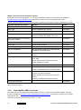
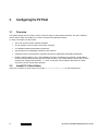
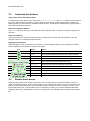
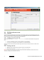
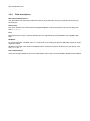
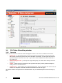
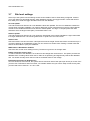
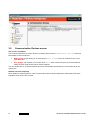
Softclinic PV Plant
Installation Guide
Real time data monitoring and long term data analysis for PV Plants
Revision History
Contact details
Version
Date
Version
1.0
07/2011
First release (Australian
version)
Weidmuller Pty Ltd
43 Huntingwood Drive
Huntingwood
NSW 2148
Australia
Tel.
+61 (0) 2 9671 9999
Fax
+61 (0) 2 9671 9900
E-Mail [email protected]
Internet www.weidmuller.com.au
Contents
Revision History ............................................................................................................................................... 2
Contact details .................................................................................................................................................. 2
Contents ............................................................................................................................. 3
1.
Introduction ........................................................................................................... 7
1.1
General description........................................................................................................................... 7
1.2
The Software package ...................................................................................................................... 8
1.2.1
Contents ............................................................................................................................... 8
1.2.2
PC Hardware requirements ................................................................................................. 8
1.2.3
Software registration ............................................................................................................ 8
1.3
Diagram of Information flows .......................................................................................................... 9
1.4
Modbus ............................................................................................................................................. 10
1.4.1
Overview ............................................................................................................................ 10
1.4.2
Modbus Maps .................................................................................................................... 10
Addresses and Offsets .................................................................................................................. 10
Data size ........................................................................................................................................ 10
1.5
Communications ............................................................................................................................. 11
1.5.1
Overview ............................................................................................................................ 11
1.5.2
Modbus RTU RS485 .......................................................................................................... 11
1.5.3
Modbus RTU RS232 .......................................................................................................... 12
1.5.4
Virtual COM ports .............................................................................................................. 12
1.5.5
Modbus TCP ...................................................................................................................... 12
Copper Ethernet Links ................................................................................................................... 12
Fibre-optic Ethernet links ............................................................................................................... 12
Modbus Gateways ......................................................................................................................... 12
2.
Installation ........................................................................................................... 13
2.1
Overview .......................................................................................................................................... 13
2.2
Planning ........................................................................................................................................... 13
2.3
Setting up the Control room PC Software .................................................................................... 13
2.3.1
Installing the MySQL Database ......................................................................................... 13
MySQL Versions ............................................................................................................................ 13
Password ....................................................................................................................................... 13
MySQL community edition Installation options .............................................................................. 14
2.3.2
Install MySQL ODBC Connector ....................................................................................... 14
2.3.3
Install PV-Clinic Runtime ................................................................................................... 15
PV Clinics Installation Manual 21/07/11 01.00
3
Installation...................................................................................................................................... 15
USB Product key ........................................................................................................................... 15
To start monitoring your PV Plant with PV-Clinic Runtime............................................................ 15
3.
Configuring the PV Plant .................................................................................... 16
3.1
Overview .......................................................................................................................................... 16
3.2
Install PV-Clinic Editor .................................................................................................................... 16
3.3
Command line buttons ................................................................................................................... 17
Copy, Paste, Insert and Delete buttons ......................................................................................... 17
Site/Table navigation buttons ........................................................................................................ 17
Disconnect buttons ........................................................................................................................ 17
Debugging/Test buttons ................................................................................................................ 17
3.4
Enable check boxes ........................................................................................................................ 17
3.5
PV-Clinic welcome screen .............................................................................................................. 18
3.5.1
Overview ............................................................................................................................ 18
3.5.2
Creating a new site or site link ........................................................................................... 18
3.5.3
Deleting a site link .............................................................................................................. 18
3.5.4
Field descriptions ............................................................................................................... 19
Site Name and Description ............................................................................................................ 19
Server Host .................................................................................................................................... 19
Port ................................................................................................................................................ 19
DB Name ....................................................................................................................................... 19
User and Password ....................................................................................................................... 19
3.6
PV-Clinics Site editing window ...................................................................................................... 20
3.6.1
3.7
Overview ............................................................................................................................ 20
Site level settings ............................................................................................................................ 21
On-Line Update ............................................................................................................................. 21
Historic Update .............................................................................................................................. 21
Historic Size ................................................................................................................................... 21
RMS values in Weidmuller modules .............................................................................................. 21
Enable string box historic when... .................................................................................................. 21
Estimating the historical database size ......................................................................................... 21
3.8
Communication Devices screen .................................................................................................... 22
User access and Emails ................................................................................................................ 22
Network size and complexity ......................................................................................................... 22
3.9
Communications Parameters Screens ......................................................................................... 23
3.9.1
General .............................................................................................................................. 23
3.9.2
Communications device settings ....................................................................................... 23
Name and Description ................................................................................................................... 23
Comm. mode ................................................................................................................................. 23
Timeouts ........................................................................................................................................ 23
Ethernet port settings .................................................................................................................... 24
Serial Port settings ........................................................................................................................ 24
4
PV Clinics Installation Manual 21/07/11 01.00
3.10
User groups screen......................................................................................................................... 25
DB User Name setting ................................................................................................................... 25
3.11
User group screen........................................................................................................................... 25
3.12
User settings screen ....................................................................................................................... 26
Username ...................................................................................................................................... 26
Enable............................................................................................................................................ 26
Host name ..................................................................................................................................... 26
Password ....................................................................................................................................... 26
Full Name and Description ............................................................................................................ 26
3.13
Assigning the User groups ............................................................................................................ 27
3.14
Email Groups Screen ...................................................................................................................... 28
SMTP Server and Firewall setup ................................................................................................... 28
Sending a test email ...................................................................................................................... 28
3.14.1
Email settings ..................................................................................................................... 29
SMTP Server and Port .................................................................................................................. 29
User ID/Password .......................................................................................................................... 29
From Address ................................................................................................................................ 29
Organisation .................................................................................................................................. 29
Subject ........................................................................................................................................... 29
3.15
Email Addresses screen ................................................................................................................. 29
3.16
Email Configuration Screen ........................................................................................................... 30
Email destination settings .............................................................................................................. 30
Enable............................................................................................................................................ 30
Sending a test email ...................................................................................................................... 30
3.17
Assigning the Email Groups .......................................................................................................... 31
3.18
SMS Communications device ........................................................................................................ 32
3.19
SMS Groups Screen ........................................................................................................................ 33
3.20
SMS Addresses Screen .................................................................................................................. 33
3.21
SMS Configuration Screen ............................................................................................................. 34
SMS destination settings ............................................................................................................... 34
Enable............................................................................................................................................ 34
Sending a test email ...................................................................................................................... 34
3.22
Assigning the SMS groups ............................................................................................................ 35
3.23
Custom Devices Screen ................................................................................................................. 36
3.24
3.23.1
General .............................................................................................................................. 36
3.23.2
Copy, Paste, Insert and Delete Buttons............................................................................. 36
Custom Group Screen .................................................................................................................... 37
3.24.1
Adding a custom device ..................................................................................................... 37
Use the Custom Devices library .................................................................................................... 37
Use the Device’s Modbus Map document ..................................................................................... 37
Ask us to do it... ............................................................................................................................. 37
3.25
Module Custom Configuration Screen .......................................................................................... 38
PV Clinics Installation Manual 21/07/11 01.00
5
3.25.1
Overview ............................................................................................................................ 38
3.25.2
General settings ................................................................................................................. 38
Name and Description ................................................................................................................... 38
Enable Module ............................................................................................................................... 38
Enable Historic............................................................................................................................... 38
Enable Alarms ............................................................................................................................... 39
3.25.3
Communications settings ................................................................................................... 39
Comm. Device ............................................................................................................................... 39
Protocol.......................................................................................................................................... 39
Modbus Station (Slave address) ................................................................................................... 39
3.25.4
Modbus Address Table ...................................................................................................... 39
Overview ........................................................................................................................................ 39
Definition and Alarms Tabs ........................................................................................................... 40
Data Name, Description, Engineering Units, Address and Data Type .......................................... 40
Scaling ........................................................................................................................................... 40
Alarm Settings ............................................................................................................................... 40
3.26
String Boxes screen........................................................................................................................ 41
3.27
Group Boxes screen ....................................................................................................................... 41
3.28
String Box settings Screen ............................................................................................................ 42
Voltage module and Voltage factor ............................................................................................... 42
Active digital output when alarm [XI+] ........................................................................................... 42
Enable lines ................................................................................................................................... 42
3.29
String Box Alarms ........................................................................................................................... 43
3.29.1
Overview ............................................................................................................................ 43
Module alarms ............................................................................................................................... 43
Alarms between modules in a group ............................................................................................. 43
6
PV Clinics Installation Manual 21/07/11 01.00
www.weidmueller.com
1.
Introduction
1.1
General description
The key to efficient energy production and consequently maximised return (and minimum payback time on
plant investment) is effective monitoring of plant production and the quick diagnosis of underperforming panels. A single panel in a string can reduce the output of the entire string and any strings connected in parallel
with that string. Softclinic PV plant provides constant monitoring of string performance and other critical plant
variables and provides instant notification to maintenance staff via email or SMS.
Weidmuller has developed Softclinic PV Plant specifically for monitoring photovoltaic plants. Softclinic PV
Plant is a professional and complete software package that complements the product range Transclinic XI
and Solar Clinics. The software manages the information generated by Weidmuller PV string monitoring
products but it has also been designed to interface directly with existing products from other manufacturers,
so it offers a global and unique solution for PV plant monitoring.
Softclinic PV Plant is divided into three programs with individual security settings for access to each program
and individual group and user security settings within each program:
•
PV-Clinic editor allows you to configure the monitoring system at installation time and to update the
information for changes to the system design. It lets you enter all the equipment to monitor (string
boxes, invertors, meters, weather stations, digital surge protection devices, actuators, etc.) so that
you can setup alarms and determine which groups of users will receive emails or SMSs instantly
when required. It also allows you to select which users will be able to monitor and analyse the data
that is collected as the plant operates.
•
PV-Clinic runtime runs on the control room computer. It collects all the data throughout the plant
according to the configuration; operates alarms and notifies users according to the setup requirements; and stores the information collected (in the popular MySQL database format) for later analysis.
•
PV-Clinic monitor allows secure access via the internet to information at one or more PV plants and
provides easy-to-use graphical analysis of current and historical data; clearing of incidents by service
technicians once inefficiencies have been investigated; and export of the data (in .xls format) and
graphs (in .pdf format for easy emailing).
Besides these powerful management features, the software has been designed with the user in mind which
is why Softclinic PV Plant is extremely intuitive and easy to use.
1.2
The Software package
1.2.1
Contents
The software package consists of a USB stick and a USB License key in a metal case as shown.
1.2.2
PC Hardware requirements
•
A PC which meets the requirements to run Windows XP, Windows 7 32-Bit or Windows 7 64-Bit.
•
Communications via Ethernet and/or RS485 - Weidmuller can supply USB to RS485 adaptors
(DCS771B); Ethernet to RS485 converters (SL-MOD-GW) and other devices according to your requirements.
•
Hard-drive using NTFS format. There are various factors and settings that determine the historical
database size requirements (see PV-Editor site level settings below). Modern drives can be around
the terabyte size and that is more than enough for most applications. In any case, a hard drive is
unlikely to last the lifespan of your PV Plant, so consideration should be given to regular backups
and eventually to replacement.
1.2.3
Software registration
It is essential that you register your copy of PV-Clinic with Weidmuller so that you can receive updates to the
software. To register send an email to the following email address:
[email protected]
You must specify the following information:
•
Company name
•
Address
•
Telephone
•
Contact Person
•
Date
•
Product code (can be viewed in Help > About).
You will receive an email confirming the correct registration of your software. If the software is not registered,
Weidmuller cannot be responsible for any issues with this or any future updates.
8
PV Clinics Installation Manual 21/07/11 01.00
www.weidmueller.com
1.3
Diagram of Information flows
This shows that how the information flows in the background for people that like a lot of detail. You don’t
need to understand this diagram to use the system. The most important thing to note is that PV Runtime
must be kept running so that the information is stored in the database and email/SMS alerts are generated
but apart from that does not require any attention.
PV Editor is important during the commissioning phase, after that mostly PV Monitor is used to check on the
system after alerts have been generated and to view performance data. Both of these programs are designed for off-site use.
1.4
Modbus
1.4.1
Overview
Modbus is a simple and robust, polled industrial communications protocol that has become the de-facto
standard for industrial applications and is now among the most commonly used systems for transferring data
between devices. PV Softclinic uses Modbus communications which allows it to monitor maximum possible
variety of measurements around the plant, from string currents and voltages to Inverter values to meteorological measurements all in one system. The connection is either serial via RS485 or via Ethernet.
For a complete description of Modbus Protocols, please refer to the www.modbus.org website.
1.4.2
Modbus Maps
Modbus allows reading and writing of ‘I/O registers’ and ‘addresses’ within any device that supports the protocol. The content of these addresses is defined by the device manufacturer and a complete map of the content is described by the devices ‘Modbus Map’ which gives tables of addresses and their meanings. An example for a simple Meteorological station might be:
Holding Register
Address
No. of
registers
Description
Data Multiplier
Units
8
1
Wind Speed
1
m/s
9
1
10Min Average Wind Speed
1
m/s
10
1
Wind Direction
1
degrees
19
2
Outside Humidity
1
%
24
1
Rain Rate
0.01
mm/Hr
25
1
UV Index
1
26
1
Solar Radiation
1
W/m2
27
1
Storm Rain
.01
mm
28
1
Current rate Of Storm Rain
.01
mm/Hr
29
1
Day Rain
.01
mm
30
1
Month Rain
.01
mm
31
2
Year Rain
.01
mm
42
1
Temperature
1
°C
49
1
Console Battery Voltage
1
Volts
52
1
Time of Sunrise
1
HHMM
53
1
Time of Sunset
1
HHMM
Addresses and Offsets
In this example, the register addresses are given as offsets. Modbus uses two address spaces:
•
Holding registers, which are 16-bit words from the start address of 30000
•
Input Registers, which are 16-bit words from the start address of 40000
So you would enter address of the temperature as 30042.
Data size
The data size is written as ‘No. of registers’, since input and holding registers are 16-bit words the device
uses mostly 16-bit values and some 32-bit values (for ‘year rain’ and ‘outside humidity’).
10
PV Clinics Installation Manual 21/07/11 01.00
www.weidmueller.com
1.5
Communications
1.5.1
Overview
This section describes the various communications options in overview. For more detail you should consult
the documentation supplied with the communication devices that you are using.
The diagram above shows the most basic install (over a single RS485 bus) where only Transclinic devices
are used to monitor the PV Array operation. This simple setup allows you to maintain maximum performance
of the PV Array by quickly informing maintenance and engineering staff of underperforming modules.
1.5.2
Modbus RTU RS485
RS485 (defined by standard EIA485) has become the workhorse for allowing multiple devices to communicate over the same twisted pair. It does not describe the protocol, connectors or cable; it just describes the
physical characteristics of the network.
Some simple rules must be followed for reliable communications using RS485:
•
No more than 32 Loads: RS485 does not specify the maximum number of transceivers but allows
for the connection of a maximum of 32 ‘unit loads’. A unit load is typically a single device although
some transceivers are now available with ½ and ¼ unit load ratings. If you are unsure it is best to
stick to 32 especially if you are using higher speeds.
•
Use a daisy chain configuration: connecting a device to the twisted pair creates a stub. Minimising
the stub length avoids transmission line problems. Transclinics provide two bus connectors to simplify the wiring.
•
Terminate each end of the bus: to avoid errors due to signal reflections and line coupling, it is necessary to terminate the bus at the beginning and at the end. Terminate the bus by inserting a 120Ω
½W 5% resistor between wire B and A (positive and negative signals) at the last and first instrument.
A common mistake is to terminate the bus at each node, which will cause problems when there are
more than three of four nodes. The network termination is necessary even for point-to-point connections and connections over short distances. Improved performance may be achieved by using a ‘failsafe’ termination at one end of the network. You should follow the device manufacturer’s recommendations with regard to ‘failsafe’ terminations.
•
Maximum bus length 1200m: for data rates above 100k, you will have to restrict the cable length
even further.
•
Use twisted pair, 24 AWG cable for the bus connections: the characteristic impedance of the cable should be 100-120Ω. A 120Ω cable presents a lighter load, so it is preferred.
•
Use a GND connection: Connect GND to the shield if a shielded cable is used. Using devices like
the Transclinic, which have isolated RS485 outputs, will reduce problems with common mode noise.
•
Use unique addresses: assign a unique Modbus slave address to each Modbus Slave device on
the network. Although Modbus allows for 0-255 Modbus slave addresses, you can still only connect
32 unit loads (including the PV Plant PC).
1.5.3
Modbus RTU RS232
Using an RS232 connection to a device may be useful for short distance point to point communications, i.e. if
you only have a single device to connect. Unless special low-capacitance cables are used, transmission distances are limited to about 50m.
1.5.4
Virtual COM ports
Since modern computers do not often come with RS232 serial ports (COM ports), you will probably use virtual serial/COM ports to connect to any serial devices. Virtual serial ports are not simple physical converters
but require driver software on the PC. These drivers are normally supplied with the virtual serial port device
or load automatically (for Windows compatible Plug and Play devices). Typical virtual serial port devices are:
•
Serial Expansion cards
•
USB to RS485 Converters
•
Ethernet to Serial converters
•
USB Dongles usually present a GSM modem interface as a virtual com port
To identify the COM port that has been assigned to Plug and Play devices go to the Device Manager in
Windows Control Panel.
1.5.5
Modbus TCP
Ethernet is rapidly overtaking serial communications for use in Industrial applications. The use of rugged industrial Ethernet products means that this is frequently the preferred option for communications in spite of
the increased cost over RS485 and other technologies.
Modbus TCP is a version of Modbus for use over Ethernet networks. Except for the communication between
devices it operates in a similar way to Modbus RTU in that devices have documented memory maps that you
can use to access and interpret data.
Copper Ethernet Links
Copper Ethernet is the most commonly used system. It is limited to 100m cable lengths so anything longer
will require optical fibre or radio links. There are a wide range of Ethernet products available to build your
network.
Fibre-optic Ethernet links
Fibre optic links can extend a Copper Ethernet network over several kilometres. You need a media converter
at each end to change between types. Optic fibre communications have another big advantage over Copper
networks because they are completely electrically isolated so problems with common mode noise and induced voltages are eliminated.
Modbus Gateways
You can put a Modbus RTU network at the end of an Ethernet network using a suitable Modbus Gateway
like the SL-MOD-GW. This can greatly simplify cabling if you already require Ethernet to that location. It also
allows you to connect distant parts of the network using a single fibre-optic link.
12
PV Clinics Installation Manual 21/07/11 01.00
www.weidmueller.com
2.
Installation
2.1
Overview
In this manual the installation process is broken into three parts:
1. Setting up the control room PC software
2. Connecting to the Transclinics and other Modbus devices
3. Setting up the plant configuration using PV editor
Important: the Control room computer must have an internet connection with a static IP address. This will
be required for Service staff to access the system and for Design staff to edit the configuration. Use of a
firewall is recommended.
2.2
Planning
Before you start it is important to plan the communications and have the information that you need for the installation. At the very least you must:
•
Decide on an administrator password for the system
•
Assign unique IP addresses to all the Ethernet devices on your network
•
Select Modbus slave addresses for each of the Transclinics and any other serial Modbus devices
•
Decide on serial communications parameters (Baud rate, Data Bits, Stop Bits, Parity and Flow control)
2.3
Setting up the Control room PC Software
2.3.1
Installing the MySQL Database
MySQL installation files
A version of the software for the MySQL database and the MySQL ODBC connector is available on the USB
stick supplied. You may wish to load the current release from http://dev.mysql.com. Alternatively contact us
for the latest supported version.
MySQL Versions
MySQL Community Edition is an Open Systems database available freely on-line. It is accessed by PV Softclinic using an ODBC connector which is available from the MySQL site. As long as the MySQL ODBC Connector and MySQL Database versions are compatible, the version of the Database is not critical. The currently supported version of MySQL is 5.1.
Password
Important: the password that you use to install the database becomes the administrator password for the
database (user = “root”). This password is also used when starting PV-Clinic Runtime. Choose carefully and
remember that the system may be operating for decades so decide where and who is responsible for keeping track of it. The password can be changed at any time using any of the MySQL management tools available from the web.
MySQL community edition Installation options
Download and save the appropriate .msi file from the MySQL website. Currently the file is available at
http://dev.mysql.com/downloads/mysql/. Alternatively contact us for the latest supported version.
MySQL should be installed with the following options (shown as they appear during the installation process):
Installation Window description
Options
Action
Welcome Screen
--
Press Next
Setup Type
Check Installation type: Typical
Press Next
Ready to install the program
--
Press Install
Wizard completed
Check “Configure the MySQL server now”
Uncheck “Register the MySQL server now”
Press Next
Welcome to MySQL Server Instance
configuration Wizard
--
Press Next
MySQL Server Instance configuration
Select “detailed configuration”
Press Next
Server type
Check “Server machine”
Press Next
Database usage
Check “Multifunction Database”
Press Next
Drive for InnoDB files
Use the default settings for InnoDB database
installation drive and directory
Press Next
Number of concurrent server connections
Check “Decision support” for number of connections
Press Next
Networking options
Check “TCP/IP networking”
Port: 3306
Check “Add firewall exception for this port”
Check “Enable strict mode”
Press Next
Default character set
Check “Standard Character set”
Press Next
Windows options
Check “Install as windows service”
Check “Include BIN directory in windows path”
Press Next
Security options
Password: XXXXXXXX
Confirm Password: XXXXXXX
Press Next
Check "Enable root access from remote machines”
Uncheck: “Create an anonymous account ”
Processing configuration....
--
Press finish
Note: these options apply to version 5.1 - the options may vary for later versions. If in doubt contact Weidmuller technical support.
2.3.2
Install MySQL ODBC Connector
Download and save the appropriate MySQL ODBC connector .msi file from the MySQL website. Currently
the file is available at http://dev.mysql.com/downloads/connector/odbc/. Alternatively contact us for the latest
supported version.
There are no options to select, simply run the .msi file.
14
PV Clinics Installation Manual 21/07/11 01.00
www.weidmueller.com
2.3.3
Install PV-Clinic Runtime
Installation
There are no options to select, simply run the file PV-Clinic Runtine.msi on the Control room PC.
USB Product key
PV-Clinic Runtime requires that you plug the installation key into one of the USB ports of the Control room
PC. For windows 7 the drivers will install automatically. For older versions of Windows, install the driver by
running the file HASPUserSetup.exe from the USB stick.
Note: without the installation key, the program will run in DEMO mode which shows simulated values but
does not collect or store values from the plant. Demo mode is indicated by in the title bar of the program.
To start monitoring your PV Plant with PV-Clinic Runtime
Click the PV-Clinic Runtime icon on your desktop, monitoring will start after a 20s delay. The USB Product
key must be connected.
3.
Configuring the PV Plant
3.1
Overview
The system design can be carried out via the internet using PV-Clinics Editor software. The same software
can be used to setup and update any number of PV plants at different locations.
To setup a new plant you will require:
•
A PC with PV-Clinic Editor software installed
•
The IP address of the PV Plant control room computer
•
The MySQL Database administrator password
•
A good name for the database (usually the site location)
•
A diagram of the communications network that shows IP Addresses and Modbus Addresses
•
Modbus Address Maps for any custom Modbus devices to be added to the network. Contact Weidmuller technical assistance (with part and model number) if you need assistance. Many devices have
already been mapped and saved as .xml files. These files can be added to the library of custom
devices for the PV-Clinics Editor program.
3.2
Install PV-Clinic Editor
There are no options to select, simply run the file PV-Clinic Editor.msi on the designers PC.
16
PV Clinics Installation Manual 21/07/11 01.00
www.weidmueller.com
3.3
Command line buttons
Copy, Paste, Insert and Delete buttons
To speed up the setup process you can use the Copy, Paste, Insert and Delete buttons at the bottom of
the screen whenever they are shown. These buttons let you build up a plant configuration by cutting and
pasting groups of custom devices, individual custom devices, custom device address maps, groups of string
boxes and individual string boxes.
Site/Table navigation buttons
The Arrows allow you to move up and down the rows a table and the Up button moves up the system tree
one level.
Disconnect buttons
These two buttons are only shown when the site is selected in the system tree. They allow you to save
changes and exit or to discard changes and exit.
Debugging/Test buttons
When the logger screen is shown there is a button to clear messages. When you are setting up a specific
email or SMS there are buttons to send test messages.
Icon
3.4
Button
Action
Copy
Copy the currently selected items to the clipboard
Paste
Paste clipboard items directly after the current selection
Insert
Insert a new (blank) line after the current selection
Delete
Delete the currently selected line
Save
Save changes and exit site (Site level only)
Discard
Discard changes and exit site (Site level only)
Clear
Clears the messages in the logger screen
Arrows
Move to the top/previous/next/bottom row of a table
Up
Move up a level in the system tree
Test Email
Send a test email
Test SMS
Send a test SMS
Enable check boxes
All parts of the system have ‘enable’ check boxes. You will see these as you start to build the system. To
make commissioning easier, uncheck these boxes as you configure the system. Then you can enable each
part as you go through and test for correct operation before carrying on to the next group or device. If you
suspect that a device or communication link is not operating correctly you can leave it disabled until later.
‘Disabled’ parts are be marked with a cross in the System tree and ‘enabled’ parts are marked with a green
tick.
3.5
PV-Clinic welcome screen
3.5.1
Overview
The first screen you will see when you start the PV-Clinics Editor program is the Site Manager window (see
above). The left-hand pane (System tree) contains a list of available PV Plants (sites). Site details for the selected PV plant are shown in the right-hand pane (Site Manager).
3.5.2
Creating a new site or site link
From the top menu select Site Manager > New Site Link, then fill in all the details in the right-hand
pane.
•
To create a completely new site, fill out the details for a new DB Name.
•
To connect to an existing site, fill out the details of an existing DB Name.
Press the ‘Connect to Site’ button (at the bottom right of the screen) to connect to the site or create a new
database.
3.5.3
Deleting a site link
•
Highlight the site connection that you wish to remove in the System tree.
•
From the top menu select Site Manager > Delete Site Link.
Note: This action only removes the connection to the site. All the site information remains and can be accessed by creating a new connection to the site.
18
PV Clinics Installation Manual 21/07/11 01.00
www.weidmueller.com
3.5.4
Field descriptions
Site Name and Description
The ‘Site Name’ and ‘Description’ fields are used locally by the Editor to help you identify the site that you
are linking to.
Server Host
Use the IP address of the PC that has the MySQL database. If this is the same PC as you are using then
write localhost.
Port
Normally the port is 3306 - unless a different port was specified during the installation of the MySQL database.
DB Name
For a new site select a suitable name. To create a link to an existing site type the DB Name exactly as it was
originally created.
DB Names are lower case and must be alphanumeric characters (numbers or letters) only (no spaces, commas, /’s. *’s, etc...).
User and Password
These are the login details set up for the administrator (user=’root’) when the MySQL database was installed.
3.6
PV-Clinics Site editing window
3.6.1
Overview
When you first connect to a site the window will appear as above. The screen is divided into four areas:
•
System tree - (in the left-hand pane), this shows a graphical representation of the PV Plant setup
which works the same way as the tree view in Windows’ file manager. To edit a particular area simply select that part of the tree. The + and – signs can be used to expand and contract branches of
the System tree.
•
Detailed settings screen - (in the top of the right-hand pane), this shows all the settings for the selected area.
•
Logger - (a white square to the bottom of the right-hand side pane), shows general messages including errors for the selected area.
•
Command line – (at the bottom of the right hand side pane), shows commands that can be used, for
example cut and paste commands, disconnect and buttons to clear the logger.
The various areas of the system tree are described below. Any new field descriptions are show as they appear.
20
PV Clinics Installation Manual 21/07/11 01.00
www.weidmueller.com
3.7
Site level settings
At the top of the system tree the settings screen shows details of the PV-Plant being configured. It allows
you to set values for plant wide settings; watch database events in the logger window. Command line buttons allow you to clear the logger and disconnect from the database.
On-Line Update
This interval sets how often the On-Line database values are updated. The On-Line database contains the
current value of all plant variables. It is used for displaying current measurements in the PV-Clinics Monitor
module so this variable determines how often the values update. For large or complex plants this value
should be set to the largest value (60s). The default value is 10s.
Historic Update
This interval sets how often the On-Line values are transferred to the Historic Database. Larger values lead
to a larger database size. It should be greater than or equal to the On-Line interval.
Historic Size
Check the historic size box and enter a time period to limit the length of time that historic records are kept. If
you will be backing up the database off site you can set this to a smaller value. Setting a smaller value will
reduce the time taken to query the database.
RMS values in Weidmuller modules
Check this box so that each reading from any Transclinic is given as an average value.
Enable string box historic when...
To reduce the size of the database, set a value for this voltage and check the box. This option prevents the
database from recording values when the PV Plant is not producing and significantly reduces the database
size. You would normally check this box and set a suitable value for the voltage.
Estimating the historical database size
As a rule of thumb, at 5s interval, the system will use less than 10M of disk space per device per month. So if
you have four Transclinics and one inverter, one weather station and you want to keep records for 25 years,
you will need around 10M x 6 x 12 x 25 = 18G.
3.8
Communication Devices screen
User access and Emails
The Communication devices screen shows a summary table of all the Communication Devices that have
been added. It also has tabs for:
•
Email groups, which allows you to select which Email Groups receive an email if there is a communication fault.
•
User Groups, which allows you to select which Users have remote access to the communications
setting screens using the PV-Clinics monitor software.
You can double-click on a communications device for more details; this will take you to the next level of the
system tree.
Network size and complexity
Since Modbus is a polled protocol, each communications device will be subjected to reasonable traffic flows
regardless of the size of the PV Plant.
22
PV Clinics Installation Manual 21/07/11 01.00
www.weidmueller.com
3.9
Communications Parameters Screens
3.9.1
General
Below the Communication devices screens are the individual communications devices. This allows you to
configure a particular RS485 link, Ethernet link or GSM modem (for SMSs).
3.9.2
Communications device settings
Name and Description
These fields allow you to add information that allows you to quickly identify the communications device. They
do not affect the device operation. The name must be unique (if it is not the program will use the first communications device with that name).
Comm. mode
There are a variety of different ‘Comm. Modes’ that are either Serial or Ethernet based. Ethernet based
modes require only the IP address and port number. Serial modes require settings for the serial port and serial communications parameters.
•
Modbus RTU – 232/422/485 - Communicates over a PC COM Port using Modbus RTU protocol.
The physical characteristics are determined by your computer hardware. Normally Modbus RTU devices use RS485 links connected to some kind of virtual port (see above).
•
Modbus RTU – UDP Raw – Connects directly to an Ethernet to serial converter using UDP protocol.
UDP protocol is a simple fast protocol that avoids some of the overheads of TCP.
•
Modbus RTU – TCP Raw - Connects directly to an Ethernet to serial converter using TCP protocol.
TCP has higher overheads than UDP because it establishes a link between computer and converter;
it is still fast enough for most applications.
•
Modbus TCP – The Ethernet TCP version of Modbus. The unofficial Port assigned for Modbus TCP
is 502.
•
SMS Modem – Sends SMS messages via a PC COM port using AT commands. The physical characteristics are determined by your computer hardware.
Timeouts
There are two timeout settings that are the same for Serial and Ethernet communications:
•
Message time out (default = 1000 msec) – the time the software waits before resending a message.
•
Time between messages (default = 50 msec) – a time delay that is inserted between messages.
Both values are set in milliseconds.
Ethernet port settings
Ethernet based communications have one setting for an IP Address in the format:
XXX.XXX.XXX.XXX:PPPP, where PPPP is the port number. The unofficial Port assigned for Modbus TCP is
502.
Serial Port settings
Serial port based communications have the usual settings which must be set to the same value as in the
communication device:
•
COM Port – The PC COM port number or virtual COM port number.
•
Baud Rate – Device Baud rate sets the data rate in bits per second.
•
Stop Bits – Stop bits allow the receiver to synchronise with each data bit. Most applications only require 1 stop bit.
•
Parity - the most common parity setting is "none", with error detection handled by the communication protocol.
•
Number of Bits - 8 data bits is almost universally used in newer applications. Change your device to
8-bits if it is not already.
Note: For virtual COM ports the serial parameters are often set in the converter hardware. Alternatively they
may be set in Windows Control Panel. The most reliable method is to set the same parameters in PV
Clinics; Control Panel and the Converter driver (if possible).
24
PV Clinics Installation Manual 21/07/11 01.00
www.weidmueller.com
3.10
User groups screen
The User groups screen shows a list of User groups and allows you to specify who can access parts of the
system via PC-Clinics Monitor software. Simply open the ‘User groups’ Tab in the appropriate menu and
check any user groups that require access.
DB User Name setting
The choice is between using the user name alone or by specifying the user group and user name separated
by a full stop. We recommend using the GroupName.UserName format to avoid duplication of user names.
This affects all logins to the system using PV-Clinics Monitor.
If you are running a second PV Plant database on the plant room PC (for testing, training or commissioning
purposes) take care not to duplicate User Names across the systems.
3.11
User group screen
Groups can be disabled or enabled and so can individual users. To delete a user select the user and then
select Users > Delete from the top menu.
To add a new group select Users > New > Group from the top menu.
3.12
User settings screen
A PV-Clinics user is defined by the username and the host ('computer') that the User connects from. To add
a new user select Users > New > User from the top menu.
Username
The username can be up to 16 characters long.
Note: depending on the DB User Name Setting of the system, you use either the Username format or
UserGroup.UserName format when logging in to the system.
Enable
Uncheck this checkbox temporarily disable access to the system for this user. For example, if the user is on
holiday or during commissioning.
Host name
The host specifier can be an IP-address or any kind of hostname and alias that can be resolved by looking
up the hostname on a server on either the local network or the Internet. Wildcards can be used. For instance
the wildcard '%' means 'any host'. So if the host is defined as ‘%' the user can connect from anywhere. Defining a specific IP address allows an added layer of security.
Password
After defining the username and specifying the host you can (and it is recommended) specify a password for
the user. The password must be retyped correctly (a green tick will appear to show that the passwords
match).
Full Name and Description
Add these details for your reference - they do not affect the operation of the software.
26
PV Clinics Installation Manual 21/07/11 01.00
www.weidmueller.com
3.13
Assigning the User groups
The screens that each user can access from PV-Clinics Monitor are set using the User Groups Tab at Communications, Custom Devices Group or String Box Group Level. Simply click the box next to the group to
toggle the access. A green tick indicates access is allowed.
The picture above shows the tab in Communication but the same tabs are shown at Custom Device Group
and String Box Group levels (shown highlighted above). PV Monitor does not allow users to access User,
Email and SMS operation.
In the example shown, Users Brad and Fred from the service department will be able to view the communications screens in PV Clinics Monitor. User David will not be able to access the information because he is
disabled as a user (because the enable checkbox is not ticked in the User setting screen). Bob does not get
access because access for his group (Engineering) is not enabled.
3.14
Email Groups Screen
The Email Groups screen sets up the SMTP server settings. Communication with the SMTP server is assumed to be via the computers internet connection and when an email is sent it will use the details given on
this page. For details of suitable settings contact your internet service provider (ISP) or your system administrator (to use your company’s mail server).
Note: Some ISPs will intercept traffic on port 25 so that you must use their mail server to relay messages.
SMTP Server and Firewall setup
Your company’s mail server will probably be set up to prevent relaying via port 25 unless specifically configured. This is a matter for your System Administrator but most mail servers can be set up to relay messages
received from a specific IP address (the fixed IP address of your PV Plant) without problems.
Your company firewall must also be set to allow messages through from the PV Plant IP Address at port 25.
Sending a test email
Select an Email address and use the
button (at the bottom of the screen) to test the
email settings. The logger will display messages showing progress.
28
PV Clinics Installation Manual 21/07/11 01.00
www.weidmueller.com
3.14.1 Email settings
SMTP Server and Port
Use the name or the IP address of an SMTP server. The Port is always set to 25.
User ID/Password
Use the login credentials for your SMTP server.
From Address
Emails sent out using this system will use this email address. Select an email address that will be monitored
in case anyone replies to the automated emails or use an address like [email protected].
Organisation
Put your company name or the name of the PV Plant in this location.
Subject
This field sets the subject line of any emails sent out by the system.
3.15
Email Addresses screen
Clicking on an email group in the system tree shows a table of the names and descriptions for people in that
group configured for that group. Double click on any name for more information or click the check box next to
the name to enable or disable that email address.
There is also and name and description field for the group and a check box that allows you to enable or disable the whole group.
3.16
Email Configuration Screen
Email destination settings
For each ‘Email address’ there is a configuration screen. This provides the usual Name and Description
fields. It also allows you to define Email (as well as CC and BCC) addresses.
Enable
Uncheck this checkbox temporarily disable emails from the system to this address. For example, if the user
is on holiday or during commissioning.
Sending a test email
Select an Email address and use the
button (at the bottom of the screen) to test the
email settings. The logger will display messages showing progress and a test email should arrive at the destination addresses.
30
PV Clinics Installation Manual 21/07/11 01.00
www.weidmueller.com
3.17
Assigning the Email Groups
Once you have setup the Email Groups and Addresses for the site, you can assign which groups get emails
when there is an alarm triggered. Operation is set using the Email Groups Tab at Communications, Custom
Devices Group or String Box Group Level. Simply click the box next to the group to toggle the setting. A
green tick indicates emails will be sent.
In the example shown, PV-Clinic Runtime will send an email to the addresses defined for ‘Bill’ when any
alarm configured for the string boxes in group inv1 is triggered.
Note: PV Clinic Runtime monitors values and sends alarm emails; if it is not running then emails will not be
sent to warn of alarm conditions.
3.18
SMS Communications device
To allow PV-Clinic Runtime to send SMS messages you need a GSM modem that accepts the extended
Hayes (AT) style commands for managing the SMS features. Most GSM modems will accept this command
set.
Set up the communications parameters by adding a communications device as shown above. If you are using a USB device it may be installed as a virtual COM Port (see above for details).
Note: ETSI GSM 07.05/3GPP TS 27.005 gives details of the AT command set.
32
PV Clinics Installation Manual 21/07/11 01.00
www.weidmueller.com
3.19
SMS Groups Screen
The SMS groups screen shows a table of SMS Groups and allows you the select the communications device
that you have set up for the GSM modem. You can click the checkbox at the left of each row to toggle the
groups enable setting. A green tick indicates that the group is enabled.
3.20
SMS Addresses Screen
The SMS Addresses screen allows you to add SMS groups and add a description of the group. It has a
checkbox for enabling the group and a table of SMS numbers that have been added to the group.
3.21
SMS Configuration Screen
SMS destination settings
For each ‘SMS Address’ there is a configuration screen. This provides the usual Name and Description fields
and allows you to define the phone number. The format of the telephone number will depend on the requirements of your modem and the PV Plant location.
Enable
Uncheck this checkbox to temporarily disable SMS messages from PV Clinics Runtime to this address. For
example, if the user is on holiday or during commissioning.
Sending a test email
Use the
button (at the bottom of the screen) to test the SMS settings. The logger will
display messages showing progress and a test SMS should arrive at the destination phone.
34
PV Clinics Installation Manual 21/07/11 01.00
www.weidmueller.com
3.22
Assigning the SMS groups
Once you have setup the SMS Groups and Addresses for the site, you can assign which groups get sent a
text when there is an alarm triggered. Operation is set using the SMS Groups Tab at Custom Devices Group
or String Box Group Level. Simply click the box next to the group to toggle the setting. A green tick indicates
an SMS will be sent.
In the example shown, PV-Clinic Runtime will send an SMS to the phone number defined for ‘Brad’ when
any alarm configured for the String boxes in group ‘inv1’ is triggered.
Note: PV Clinic Runtime monitors values and sends alarm SMS messages; if it is not running then SMS
messages will not be sent to warn of alarm conditions.
3.23
Custom Devices Screen
3.23.1 General
One of the strengths of PV-Clinics software is the ability to interface to a variety of devices around the PV
Plant and to monitor and collect information from those devices. The de-facto standard for industrial plant
communication is Modbus and there is a large array of products that have Modbus interfaces. To include any
of these into the PV Plant monitoring system you simply set them up as custom devices. The setup is extremely flexible and, for simplicity, common devices can be imported and exported as .xml files to form a library that greatly simplifies the setup process.
3.23.2 Copy, Paste, Insert and Delete Buttons
To speed up the setup process you can use the Copy, Paste, Insert and Delete buttons at the bottom of the
screen. The buttons are:
Icon
36
Referred to as
Action
Copy button
Copy the currently selected item to the clipboard
Paste button
Paste items on the clipboard directly after the current selection
Insert button
Insert a new (blank) line after the current selection
Delete button
Delete the currently selected line
PV Clinics Installation Manual 21/07/11 01.00
www.weidmueller.com
3.24
Custom Group Screen
3.24.1 Adding a custom device
Use the Custom Devices library
There is a library of custom devices stored as .xml files. To use a library device, select the appropriate custom device group in the system tree then select ‘Custom Devices > Load From Library..’ from the
top menu and choose the appropriate file.
You can make changes to the custom device and export the changes back as a new library item. Simply select the .xml file for the device you wish to add, or one that has a similar mapping, make the changes and
export with a new filename.
Use the Device’s Modbus Map document
Use the insert button to add a new device, the screen for that device will be shown and you can enter the details as required. For Modbus devices there is [usually] a document that describes the Modbus address map
available from the manufacturer. To add a new custom device you will normally need a copy of this so that
you can setup the map of the device registers.
Ask us to do it...
Weidmuller technical support can help you with this process. You will need to supply model number details
and we can supply you with an .xml file to add to your library.
3.25
Module Custom Configuration Screen
3.25.1 Overview
The Custom module setup screen allows you to enter details from the custom device’s Modbus map so that
PV Clinics can record and monitor the data. It also allows you to set alarms on each value supplied by the
custom device. If the alarm conditions are triggered a SMS and/or Email will be sent according to the configuration for that Custom Devices Group.
Normally you will add a device from the Custom Device library and the Modbus Map will already be configured. You can use this screen to make adjustments and set alarm values. You should also go through the
Names and Descriptions of each device parameter and remove them if they are not important to your application. Removing redundant values will make the map simpler and easier to follow.
3.25.2 General settings
Name and Description
These fields allow you to add information that allows you to quickly identify the custom device. They do not
affect the device operation. The name must be unique (if it is not the program will use the first communications device with that name).
Note: The name will become the table name in the database where the measurements taken from this device are stored.
Enable Module
Uncheck this box until you are ready to commission this device. You can also use it to temporarily disable
recording for the device while it is being serviced.
Enable Historic
Check this box if you wish to keep a history of readings from the device. A complete set of all enabled measurements will be recorded at the interval you entered the site level ‘Historic update’ setting and kept as long
as specified in the site level ‘Historic Size’ setting.
38
PV Clinics Installation Manual 21/07/11 01.00
www.weidmueller.com
Enable Alarms
Check this box if you have set any alarms for this device. See below for an explanation of how to set alarms.
3.25.3 Communications settings
Comm. Device
Select the relevant Communications device from the drop-down list.
Protocol
Leave this setting untouched.
Modbus Station (Slave address)
Select the Modbus slave address for the device. This setting is only used if the custom device is using a
serial version of Modbus.
3.25.4 Modbus Address Table
Overview
The center section of the right hand pane shows a table of Modbus Addresses. You can add, cut, copy,
paste, delete records and navigate around the rows of the table using the command buttons. Below the table
are two tabs which you use to set the contents of each address. You may wish to review the Modbus section
of this manual for a brief explanation of how Modbus addressing works or visit the Modbus website at
www.modbus.org.
Hint: you do not have to set up the entire Modbus map for the device. These maps are often extensive but
restricting the setup to critical measurements can significantly reduce setup time. It will also reduce the time
to process the device measurements and reduce the database size if the ‘Enable Historic’ checkbox is
ticked.
Definition and Alarms Tabs
When you have selected a row in the Modbus Address table, you can alter the settings in the Definition tab
(below the table) and you can set alarms to monitor any measurement by selecting the Alarms Tab.
Data Name, Description, Engineering Units, Address and Data Type
Choose a suitable data name for the location and add a description to help you interpret the reading. Select
suitable engineering units from the drop down box after the Data Name.
Take the Address and Data type from the Modbus Map for the device. Do not enter the address as an offset,
enter the full address (e.g. 30830 not 830).
Note: The data name becomes the Field Name in the database table for the device.
Scaling
To scale the raw data from the Modbus register enter a range for the raw data (Max Raw and Min Raw
fields) and the corresponding range for the engineering data (Max EU and Min EU fields). Add an offset in
engineering units to offset the engineering units.
In the example shown above, the raw data of 0 to 1000 represents 0 to 100.0 m/s.
Alarm Settings
You can set alarms in the Alarms Tab. These will trigger SMS or Emails according to the select for the relevant custom devices group. No alarms will be sent unless the checkbox for Enable Alarms is ticked.
In the example shown, an alarm is set for wind speeds above 20m/s which last for more than two minutes.
40
PV Clinics Installation Manual 21/07/11 01.00
www.weidmueller.com
3.26
String Boxes screen
The String Boxes screen shows a list of all String box groups. There is also an Alarms category that allows
you to set system-wide alarms for all string boxes and for groups of string boxes. There are no general settings on this screen; it simply shows a table of the String box groups that you have defined.
You can use the command buttons to add or delete groups from the PV Plant setup. You should group string
boxes together if they can be expected to produce the same power output, for example, if the modules are
angled the same way to the sun, or are connected to the same central inverter.
3.27
Group Boxes screen
The String Box group screen shows a list of String Boxes in that group. It also allows you to define who will
receive SMS and Email alerts when an alarm condition is triggered for any string box in that group. There is
also a Tab that determines which Users have access to the group data through the PC Clinics Monitor software.
3.28
String Box settings Screen
The Module string box setting screen has a similar layout to the Custom devices screens. The difference is
that you can only add preconfigured string box types and there is no alarm setting at register level. Alarms
are set for all string boxes in the alarm screen shown below.
The settings screen still allows you to change ‘Name’, ‘Description’, ‘Comm. Device’ and Modbus station values as well as enabling the module and alarm monitoring for the module in the same way as custom devices.
Note: The ‘Name’ field is used for the database table name for that device in the historical database.
Voltage module and Voltage factor
These values are used to compensate for differing cable losses around the plant.
Active digital output when alarm [XI+]
Each Transclinic XI+ has a digital output. If you check this box and there is an alarm condition for any of the
strings monitored by this Transclinic it will operate the digital output. The output can be attached to a relay
that operates a light on top of the combiner box to make it easy to find faults. You can use it however you
want.
Enable lines
You can enable or disable each measurement by clicking on the beginning of the line. A green tick will appear if the value is being monitored.
42
PV Clinics Installation Manual 21/07/11 01.00
www.weidmueller.com
3.29
String Box Alarms
3.29.1 Overview
There is one screen for setting all string box alarms. It is divided into two sections:
•
Module alarms are triggered if any string monitoring module meets the conditions. SMS or Emails
are then sent according to the Group SMS and Email settings.
•
Alarms between modules in a group are triggered if the values from any module deviate from the
average of all modules in the same group.
Deviation alarms operate by comparing the value from an input against an average value calculated from
several units.
Module alarms
Module alarms can be as shown on the screen. Minimum string current and voltage down alarms should only
be used for fault finding over short time periods as they will trigger when the plant is not producing.
Alarms between modules in a group
PV Clinic Runtime compares the values from each module in a group against the average value for the entire group. If the deviation from the average exceeds the group average an alarm is given (by SMS or Email
according to the configuration). These alarms allow the quick identification of underperforming strings so that
corrective action can be taken to restore production.