1
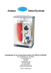
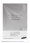
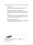
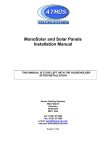
Air Source Heat Pump
Installation and Maintenance Manual
Model Numbers:
RC090MHXEA
RC160MHXEA
January 2013
www.samsungehs.co.uk Hendra - January 2013
1
The outdoor unit (boiler)
Deciding on Where to Install the Outdoor Unit
The outdoor unit must not be placed on its side or upside down, as the compressor lubrication
oil will run into the cooling circuit and seriously damage the unit.
Choose a location where the noise of the Air to Water Heat Pump when running and the
discharged air do not disturb any neighbours.
Install the outdoor unit on a flat, stable surface with plenty of drainage, gravel or grass is
ideal; make sure the base can support its weight
Position the outdoor unit so that the air flows into an open area.
Place the outdoor unit where there are no plants and animals
When installing the outdoor unit near sea make sure it is not directly exposed to sea breeze.
The golden rule is, if you can see the sea from the position of the outdoor unit you need to
apply Blygold or equivalent anti-corrosion coating on the whole unit.
The unit needs to be securely
mounted at least 100mm off the
ground on rubber feet or wall
brackets, the unit must be bolted
down for security using 10mm bolts
and Zebedee bolts.
The unit must have adequate
drainage away from the unit; it can
produce up to 6 L / hour.
There is a drainage kit included
which we recommend you don’t
use, its best to let the unit drain into
the ground. The drain holes in the
unit are clearly shown, if a drip tray
is used it must be 25mm longer and wider than the base of the unit to catch all the drips.
Dimensions:
Size 16 - 1420mm (h) 940mm (w) 330mm (d) 103kg
Size 9 - 998mm (h) 940mm (w) 330mm (d) 75kg
The space around the unit is very important, allow:
150mm to the left hand side (facing the front of the
unit), 600mm to the right of the unit, 300mm to the
rear of the unit and 1500mm to the front of the unit.
The unit will not benefit from being mounted on the
North or South of the building any aspect is fine, you
should avoid very exposed positions to avoid wind
blowing into the back or front of the unit and very
sheltered positions.
An exposed location may increase difficulty for full unit defrost.
The Control Box
When the heat pump is delivered it comes with a control box which also contains the flow
switch. Install the control unit indoors as it’s not waterproof.
It needs to be sited within 15m of the hot water cylinder, 100m of the outdoor unit and as near
as possible to the pump, flow switch and any zone valves.
The box is 323mm wide, 339mm high, 131mm deep
www.samsungehs.co.uk Hendra - January 2013
2
The 9kW unit has 1 inch BSP
male connections; these should
be connected to flexi hoses.
To maintain flow rate we
recommend 22mm pipework is
used with this machine.
All Pipework including the flexis
need to be insulated with 23mm
lagging
It is essential to connect an
expansion vessel, pressure
gauge, pressure relief valve, filling
loop, magnetic filter/strainer and
automatic bypass.
A pump will be required, normally
in the flow. Dependant on system
resistance some times, 2 pumps
may be required.
Either a 3 port diverter valve or 2
x 2 port valves need to be
installed for domestic hot water
prioritisation.
A flow meter / setter and flow
switch should be installed and a
strainer in the return.
The domestic hot water cylinder
must be manufactured specifically
for the heat pump.
www.samsungehs.co.uk Hendra - January 2013
3
The 16 kW unit has 1 inch BSP
male connections, these should
be connected to flexi hoses
(supplied).
To maintain flow rate we
recommend 28mm pipework is
used with this machine.
All Pipework including the flexis
need to be insulated with 23mm
lagging
It is essential to connect an
expansion vessel, pressure
gauge, pressure relief valve, filling
loop, magnetic filter/strainer and
automatic bypass.
A pump will be required, normally
in the flow. Dependant on system
resistance some times, 2 pumps
may be required.
Either a 3 port diverter valve or 2
x 2 port valves need to be
installed for domestic hot water
prioritisation.
A flow meter / setter and flow
switch should be installed and a
strainer in the return.
The domestic hot water cylinder
must be manufactured specifically
for the heat pump.
www.samsungehs.co.uk Hendra - January 2013
4
Other components you need to supply and fit:
An expansion vessel, pressure gauge, pressure relief valve and filling
loop
Most heating engineers use a robokit with the appropriate size expansion
vessel, this is sized exactly the same way as when using a boiler.
Pump
Your pump needs to supply 20l/min for the 9kW and 30l/min for the 16kW unit.
The static resistance through the unit is 10kPa for the 9kW and 15kPa for the
16kW unit. The flow meter has a resistance of around 5kPa
The cylinders (Gledhill) have a static resistance of 5kPa for the heat pump coil
and 19kPa for the solar coil.
The total resistance of the components will be approximately 39kPa for the size
9 unit and if the cylinder is piped using both coils and approximately 44kPa for
the size 16 unit if using both coils.
Flow switch and flow meter
The unit requires 16L / min flow at all times, if you don’t achieve this
E911 error will occur to check this flow switch is installed. The flow
switch comes with the control box.
The flow Switch MUST be installed in horizontal pipe with at least
150mm of straight pipe either side, connection is 1” female BSP. The
wire is 2m long and needs to connect into the wiring station. This wire can be extended to
suit. We recommend a flow meter is installed into the flow side of the flow switch as per the
photo. Adaptors may be required to enable this join. The flow switch is not IP65 rated
(weatherproof) and so must not be installed externally.
Diverter valves
If you require domestic hot water and heating, diverter valves are
required, you need to supply these. You can use a three port or 2
port valves. The three ports must be of the diverter variety or wired
as a diverter, see wiring.
Bypass Valve
You must install a bypass valve in the heating circuit as far away from the heat
pump as possible. The bypass valve enables flow to be maintained as the tevs
shut down at all times to prevent unit flow fault.
Buffer vessels
We don’t normally use buffer vessels on Samsung EHS systems; as long as the water volume
circulating is over 20 Litre. The inbuilt variable speed compressor means the unit can operate
without a buffer.
1m of 22mm pipe holds 380 ml of water, if you add the volume in the unit and components
and make sure you put the bypass valve more than 25m from the heat pump your system
volume will be adequate. When utilizing multiple units, a buffer or low loss header is required
to hydraulically join the units.
Magnetic Filter
A magnetic filter with strainer must be installed in the return to the unit. A magnetic filter
ensures that debris/foreign materials do not cause restrictions within the pipework / system.
Glycol
A propylene glycol mixture must be utilized to prevent freezing of the water within the system.
It is important that the glycol concentration is adequate to protect the unit in case of power
failure in very cold conditions. If the unit freezes up there will be no warranty. Manufacturer
dependant, a mix of around 25% should suffice.
www.samsungehs.co.uk Hendra - January 2013
5
The Cylinder
The cylinder needs to be installed less than 15m from the control box to allow for the
temperature sensor cable. Note the size and weight of the cylinder. Full installation
instructions are included with the cylinder.
We only recommend using Gledhill heat pump stainless steel cylinders however other
cylinders can be used IF the coil area is more than 2.5m^2. Smaller coils are not acceptable
and cannot be used. Please do not attempt to utilize a standard central heating, non-heat
pump optimized cylinder. Cylinders can be pressurised or open vented.
When using Gledhill cylinders both the heat pump
(top) coil and the solar (bottom) coil should be
used. If no solar thermal is being used the heat
pump should connect to both coils as per the
recommendations in the Gledhill installation
instructions, and oversized by 30% to take into
account 0kW input from solar thermal in winter.
G3
The G3 regulations state in section 3.13a “for all
indirect heat sources an overheat cut out to
disconnect the supply to the stored vessel in the
event of the stored water overheating must be
employed so that the temperature of the stored
water does not exceed 100C”.
For this reason the heat pump cylinder comes with
a 2 port valve and tank stat. The valve can be
installed in the flow as per the diagram.
However as the refrigerant used in the Samsung
EHS is R410A it is not able to physically heat above its critical temperature of 72.8C.
Many heating engineers do not install this valve.
If solar thermal is used it needs to be connected to the bottom coil of the cylinder as shown.
www.samsungehs.co.uk Hendra - January 2013
6
www.samsungehs.co.uk Hendra - January 2013
7
www.samsungehs.co.uk Hendra - January 2013
8
Wiring and Power Supply Information
Power
The EHS system needs 2 power supplies:
One connects into the outdoor unit, 20 Amp for the 9kW and 32
Amp for the size 16
The one for the control box is 16 Amp and wires into the top of
the breaker (mcb) in the box
Immersion Heater
The immersion heater is connected into the control box terminals
A3 Neutral and A4 Live, The control box controls the operation of
the immersion heater. If a fused spur is used it must be labelled
as switching it off will cause an error.
Communication cable
This must be run from the outdoor unit to the control box. Use 2 core flex 0.5-1mm (its 16V
ac)
Sensors
The blue cylinder sensor plugs into a socket T4 on the
controller PCB and into the control sensor pocket in the tank in
the top ½ of the cylinder. The tanks sensor needs to go 115mm
into the tank; it must be clipped so it can’t pull out.
The red safety sensor is to avoid over temperature, when using a backup boiler or heater, it
clips to the outlet of the boiler. If no backup boiler is used the sensor is not needed. It plugs
into a red socket T3 on the controller PCB
There is a black wire with a red plug in the box, this is not used.
Sensors cannot not be cut or extended. Keep sensors away from mains cables please
Diverter Valves
Using a three port valve
3 way valve if A to heating & B to HW wire both the white and grey wires to B9, Blue to B7 the
rest are not used. If valve is piped the other way round use terminal B10 instead of B9
Using two port valves
2 port valve for Hot water, wire brown wire to B9 and Blue to B7, the rest are not used.
2 port valve for heating zone 1 wire B14 live and B11 Neutral
2 port valve for heating zone 2 wire B18 live and B17 Neutral
Thermostats/ timers and under floor heating manifolds
We recommend in all cases the heating should be controlled by an external field supplied
room stat / setback stat time clock etc. or run signal from a boiler enable signal from under
floor manifolds. If both rads and u floor are used in the same system the heat pump can be
controlled to run at 2 different set points one for each thermostat terminal.
To run the unit with radiators make a connection from B20 – B24, to run the unit from under
floor heating make the connection from B20 - B22.
B20 is permanently live 240V ac. B19 is Neutral
When the stat is made the unit will run, when the stat opens the unit will stop. Hot water
production is not affected and will always take priority.
Pump
The circulation pump must be wired Live to B6 and neutral to B5, MAX pump power is 500
Watts. If two pumps are used wire them both to these terminals
www.samsungehs.co.uk Hendra - January 2013
9
Start Up Procedure
Disable the cooling function, with the power OFF, remove
the front of the remote controller, slide it upwards, turn it
over and flick dip switch 1 to on.
Cooling will no longer be available
On the outdoor unit remove the front cover, there
are 2 screws at the top and one at the bottom, slide
the cover down. Inside the unit is a baseplate
heater which is not normally required in the UK,
disconnect the bottom wire white plug and tuck it
out the way
Filling and flushing:
The Building Regulations for England and Wales, Part L, 2006, now require a central heating
system to be cleaned and inhibited chemically whenever the boiler is changed or any major
works are carried out to the system.
When installing any Heat pump we insist on a thorough system flush prior to connection of the
new equipment, your warranty will be at risk if a suitable flush is not carried out and the
system becomes blocked during normal operation.
Power flushing
The recommended procedure is to power flush the system in both forward and reverse
directions at 110% of the normal flow rate and to use a chemical flushing agent where
required.
Filling
Using the power flusher fill the system with water and 25% Propylene Glycol to more than 1
bar. It’s a good idea to note what the flow rate is through the system on the inline flow meter.
DON’T fill the unit with a hose expecting no air locks, the heat pump is prone to air locking at
the outdoor unit, there is no auto air vent here.
Don’t pour neat glycol into the unit; there is no chance of the heating pump moving neat
glycol around the system.
Powering Up
Apply power to indoor control box first then the outdoor unit.
On the outdoor unit PCB the display will show 88 88, It will then
say Ad meaning it’s checking the addresses for you.
Soon it will say Ad then flashing numbers 00, 01 02 etc. Finally it
will count up to 15. It has now finished addressing.
It will now flash a message like 00 00, dE, F0 etc.
This is it telling you the units it can see. The unit is now ready to
run.
If the outdoor unit / remote controller show E201 there is a comms
error. Check the comms cable F1 and F2.
In the middle of the control box PCB you will see two tiny leds one
red and one orange flashing. The red one shows the signal leaving
the PCB and the orange shows the signal coming back from the
outdoor unit.
www.samsungehs.co.uk Hendra - January 2013
10
Starting it up in heating mode
If you have two port valves you should find the heating
valves are open and the hot water valve closed. If you
have a 3 port valve it should be open to heating mode.
Start the unit my Pressing heating on off button (top left
inside the door) to start the unit, set the mode to heating
(sun symbol)
Set the desired water temperature i.e. 50C using the up
and down buttons.
Flow Switch and E911 READ THIS
When the pump is running a little house with a circle around it in the status window of the
controller.
The unit wants to see 14 l / min flow to activate the flow switch, if there is not enough flow a
E911 fault will show every 15 seconds
Check:
The flow rate on the flow meter it MUST be over 15l/min
The flow switch is connected to the PCB of the control box
The flow switch is round the right way you can turn the head, there is an arrow
All valves are open.
The pump speed is set at highest
There is no air in the system
There is water in the system
If none of this works you need a bigger pump or its air locked
To clear the fault stop and start the machine again with the button on the remote controller.
After 3 mins of pump operation the outdoor unit will start, don’t rush the system it takes time
Caution in Cold weather
If the water in the system is below 10C the heat pump WILL NOT
START.
Press the blue view button you can see 4 sensor readings, press it
until the pump symbol shows (a circle round a house). This is the
water temperature, if it’s below 10C the unit will not start but the
pump will run.
You must warm up the water to get the unit to run, the easiest way
to do this is to add a tank and use the immersion to warm up the
tank first, the warm water from the tank will preheat the heat pump
and it will start to operate. For more info see page 13.
Set up the bypass valve with radiators
In heating mode check the unit is pushing water into the heating circuit only. Open the bypass
valve fully, if you are not sure set it to its lowest setting. Now close every radiator on the
system except one.
Using the flow meter check the flow rate is above 15/l to avoid E911 faults. Adjust the bypass
valve to achieve this. If 911 occurs clear the fault switching the unit on and off at the remote.
The bypass is set now open the rads again.
Set up the bypass valve with U floor heating
In heating mode check the unit is pushing water into the heating circuit only. Open the bypass
valve fully, if you are not sure set it to its lowest setting. If 911 occurs clear the fault switching
the unit on and off at the remote.
Using the flow meter check the flow rate is above 15/l to avoid E911 faults. Adjust the bypass
valve to achieve this. If 911 occurs clear the fault by sending an off and then an on command
to the unit. Reset the power to the ufloor manifold to do this.
The bypass is set now turn up the wall stats again.
www.samsungehs.co.uk Hendra - January 2013
11
What the symbols mean:
Setting the correct time
www.samsungehs.co.uk Hendra - January 2013
12
Telling the unit it has a tank.
When the unit is delivered it doesn’t think there is a
hot water cylinder tank installed. You have to tell
the unit about the cylinder.
Press test button for 3 seconds
The screen will start to flash,
Press up twice, 30 will appear
Press set (grey) 3011 will appear Press set (grey),
0 will appear Press up once 1 will appear
Press set (grey) once 3011 will appear press
cancel delete 2 x to return to normal screen
IF E904 error shows the tank sensor is not
connected
Starting the System in hot water mode
Press Hot water on off button to start the
unit, top left button.
The unit speed is adjusted with the std, eco
power button, set to middle position, 2 dots
showing.
Set the desired temperature 48C using the
up and down buttons. This can ONLY be set
if the Heating function is switched OFF and
HW is on
NOTE when the unit is heating the tank this
coke can symbol shows on the controller.
After 20 mins of operation if the tank temperature is not reached the immersion heater will
start to help out. This time can be adjusted using setting 3032
Press the blue view button you can see 4 sensor
readings, press it until the tap symbol shows.
This is the tank temperature. It will display for about
10 seconds. Check the temperature is not fluctuating
more than 1C in this time. If it is the sensor is not
installed correctly or is damaged. If this happens the
system WILL NOT WORK PROPERLEY
www.samsungehs.co.uk Hendra - January 2013
13
Run test in hot water mode
In hot water mode check that the 3 port valve or the 2 x 2 ports are sending water into the hot
water cylinder, if not check the wiring.
Using the check button (blue) on the remote controller check the hot water cylinder
temperature and note it down, the hot water temperature is displayed when the tap symbol
shows.
After 15 minutes of running check the hot water temperature again, it should have risen, again
note the temperature.
If the temperature has not raised check the temperature sensors is installed properly and
again check the operation of the 3 port or 2 port valves. If the unit is running well it should
heat the cylinder to 48C without needing the immersion heater
Setting up the tank immersion heater
The Gledhill tank has an immersion heater with its own stat; this
MUST be set to 70C. This is to avoid the immersion heater cutting
out before the legionella function is complete
Tank timer
To avoid the tank heating being switched off we always add 2 on
timers a day one at 3-00 am and one at 15-00 pm.
Press daily button once, no 1 and on shows, press set (grey), press up or down until the tap
symbol shows at the top of the screen with
2 dots press set, adjust hours with up or
down button to 3 am press set, minutes
flash press set. Now everything flashes
press set (grey). No 2 appears do the
same again but for 15-00.
After everything is set no 3 will show.
Press cancel delete twice, the normal
screen will show. Daily will appear next to
the time. The timer is active
To delete the timers press daily 2 x the set
schedule will show, press and hold cancel
delete for 5 seconds, keep doing this until
no1 shows, press cancel delete 2 x and in
the normal screen daily will have
disappeared.
The hot water tank has priority over the heating, if the tank temperature falls 5 degrees below
its set point the unit will automatically switch to heating the cylinder. Once set temperature is
achieved the unit will go back to heating the house.
The hot water cylinder loses almost no heat (1/3 a degree an hour) if no hot water is used.
The hot water cylinder takes less than an hour to heat up from cold. If you need hot water
very fast the DHW button forces the unit to heat the water flat out, the unit will stay in this
mode until you press the DHW button again
To protect from legionella the tank is heated to 60 degrees C once a week automatically.
Performance testing
With the unit running flat out measure the temperature of the air temperature as it enters the
coil and the ambient temperature well away from the unit? They need to be the same for the
unit to operate properly.
Not enough hot water.
The Water storage temperature is lower (48C) than a normal fossil fuel cylinder. It’s important
to check that any shower or bath mixers do not further reduce the water temperature. Using
your thermometer check that the hot water comes out the tap at the same temperature it
leaves the cylinder. If it doesn’t you might need to make adjustments to taps mixers etc.
DON’T raise the tank temperature to compensate.
www.samsungehs.co.uk Hendra - January 2013
14
Field Settings
Many field settings will need to be made: NOTE the set button is the grey one not the blue
When finished or if you get lost press cancel delete 2 x to return to the normal screen
Note: if you set a field setting and go back to check it, it will not have changed, the field
setting do not get written to the PCB until you finish setting and exit.
Field settings to set see user manual for a full list
1061
2011
2012
2021
2022
2031
2032
2091
2092
3011
3025
3032
3042
3043
3044
3061
30s
-2
+15
45C
37C
50C
35C
1
1
1
50
30
3
60
1
length of time backlight is on in the Samsung rc
low ambient setting for optimisation set to -5 in Scotland
high ambient temp for optimisation
for u floor. Hi water temp for optimisation
lowest water temp for optimisation
for rads. Hi water temp for optimisation
lowest water temp for optimisation
tells unit to use a u floor run signal
tells unit to use an external room stat
tells unit it has a tank connected
mins, max tank heating time, make longer for big tanks i.e. 75 mins for 300L
mins, delay time before immersion heater starts in tank mode
Tuesday day legionella happens (always use Tuesday)
am time it happens
C legionella temp
if a solar thermal system is installed
A full list of field settings are in the installation and user manual which come with the outdoor
unit
www.samsungehs.co.uk Hendra - January 2013
15
Operating the System in heating mode using an external
thermostat and / or a boiler run signal from an under floor
manifold.
You have now set the unit up to run from an external signal; the controller no longer drives the
unit.
Using a field supplied room thermostat or signal from an under floor heating system. This is
wired to the thermostat terminals for radiators wire from B20 – B24, for under floor heating
wire to B20 - B22
When the contact is made the unit will start and the water temperature will be controlled by
the boiler, you will not have any control over it. The water temperature is determined by the
outdoor temperature; the colder it is outside the warmer the water.
You will see 0.0C on the screen; this shows the unit under external control using weather
compensation function to work out the water temperature. You set this up in the field settings
2011 to 2031. If you need to boost the heating water temp this can be done by pressing the
silver up and down buttons. This boosts the radiators by up to +5 C but warning this will cost
more money to run.
The heat pump is operated using a signal from a room stat (field supply) or from the under
floor heating manifold only. When you make a run signal a sun will appear in the screen of the
RC, the pump will also start.
When an external stat or run signal is used most of the functions of the Samsung remote are
disabled.
A waging finger shows at the bottom to show this.
All these buttons are disabled and the functions they control are also disabled
Note: when the heating command is sent to the unit it will not start for 3 minutes. And
when the thermostat or signal is removed the pump will run on for up to 6 minutes.
www.samsungehs.co.uk Hendra - January 2013
16
Maintenance Monobloc systems
The Samsung heat pump should be maintained at least once a yea r to comply with warranty
and RHI.
Maintenance procedure
Stop the unit, clean the strainer or magnetic filter in accordance with manufacturer’s
recommendations and replace it.
Test the concentration of the Anti-freeze (glycol) in the system using a Glycol tester the level
should be 25%. If you don’t have a glycol tester a Samsung glycol tester can be bought from
your heat pump supplier or online.
Refill the unit, pressure should be 1 -2 bar,
We need to test the operation of the unit against the hot water cylinder. So first we need to
draw off 20 liters of water, run a couple of taps for 5 mins to achieve this.
Test the unit as described on page 13 and 14
The unit should start up automatically in hot water mode, if it doesn’t press the top right button
on the controller, in 3-4 mins it will start heating the tank, a coke can symbol will show in the
status section of the remote controller.
The heat pump should be able to achieve 48C cylinder temperature without using the
immersion heater.
While running, check the coil on the heat pump for damage & debris, the coil needs washing
we recommend you use Pro-universal heat pump cleaner, this is available online or from your
heat pump supplier, one bottle will do up to 3 units. Instructions are given on the bottle.
Hot water Cylinder:
Check electrical connections & sensor are fixed properly and
the overheat thermostat is set to 70C.
Overheat Thermostat Adjustment
Press the silver immersion button on the Samsung remote controller; this will force the
immersion heater on. Check immersion heater works properly, Measure the current drawn by
the heater; it should be 12-13 Amps.
Measure the temperature of the flow using the remote controller.
Measure the flow rate from the flow meter.
With the unit running flat out measure the temperature of the air as it enters the coil and the
temperature of the air in the garden. They should be the same check cold air is not
recirculating.
www.samsungehs.co.uk Hendra - January 2013
17
Leave this with the Homeowner
Your Samsung heat pump heats the house and hot water cylinder much like a normal
fossil fuel boiler however there are a couple of differences which you should notice.
1
The radiator temperatures are lower than normal and will alter as the outdoor
temperature changes. The colder it is outside the warmer the rads and vice versa.
This function is automatic and is designed to save you money. At hottest they will
reach 50C. If you would like a constant radiator temperature this can be set by an
engineer but it will increase your run costs by up to 25%.
2
The system is designed to run continuously in cold weather, turning the system on
and off will make the house uncomfortable and will increase your run costs. The most
efficient way to run this heating system is to leave it running at the set temperature 24
hours a day in winter time. If you turn off the heating and let the house get cold (less
than 17C) it will take a very long time to warm back up to a sensible temperature.
Your systems have been set up to be simple to operate.
The Samsung controller looks like this, you should not use
this or press the buttons on it, it is for commissioning and
making settings to the system only.
You should see 0.0C on the screen this means the unit is
under external control from a room thermostat.
If the system goes in to fault, the screen will show a number
at the bottom starting with E, for example E911 – A00
The engineer will want to know this number when you call
him.
Heating
Control of the heating is by your wall mounted thermostat, not the Samsung controller; you
need to read the instructions for this thermostat as its field supplied. The boiler will run when
told too by the thermostat. DON’T set the room temperature too low, the heat pump takes
time to recover the house temperature, as a rule don’t set the temperature more than 2
degrees below your normal set temperature when you go out of the house or it will take a long
time to recover.
To switch off the heating in summer set the temperature down to 16C to avoid the heating
starting up.
To control the temperature in your rooms please use the radiator valves.
Hot water
Your system will keep the hot water cylinder hot at all times automatically, as you use the
water the heat pump will constantly top up the cylinder. A cold cylinder should be reheated
within an hour. An anti legionella operation will be completed at a predetermined time every
Tuesday morning.
Warranty Important
Attached to this document is a warranty page your installer must fill in both sides and return it
to activate the warranty. No claim will be processed without this paperwork being returned.
www.samsungehs.co.uk Hendra - January 2013
18
Samsung EHS Warranty
Unit 2 Warrior Park
Eagle Close
Chandlers Ford
SO534NF
Web site www.samsungehs.co.uk
Email [email protected]
Warranty Registration Card
Please complete both sides of this warranty
card and return it to activate the warranty
Installer Name and Address
telephone number & contact name
Installation Address
Where was the unit purchased:
Date Installed
Date of
commissioning
Heat Pump Model No
Serial No
Hot water Cylinder
installed
Yes/no
Cylinder make
and model no
Warranty period
Standard 3 years
Optional
extended
warranty
Extended 7 years
Please sign below and return to our Warranty Dept. via fax 08458430122, email
[email protected] or post to the address above. Once received and if
accepted we will then arrange for the replacement component(s) to be despatched.
Signature
Date
www.samsungehs.co.uk Hendra - January 2013
19
Samsung EHS Warranty
Unit 2 Warrior Park
Eagle Close
Chandlers Ford
SO534NF
Web site www.samsungehs.co.uk
Email [email protected]
Warranty Registration Card
Please complete both sides of this warranty
card and return it to activate the warranty
For terms and conditions of the warranty please refer to the warranty document at
www.samsungehs.co.uk / information / downloads / technical downloads.
www.samsungehs.co.uk Hendra - January 2013
20