1
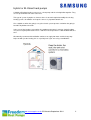
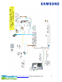
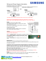
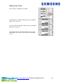
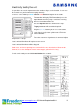
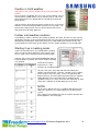
Air Source Heat Pump
Installation and Maintenance Manual
Combi Hybrid
Model Numbers:
RC090MHXEA
RC160MHXEA
www.samsungehs.co.uk ©G Hendra September 2014
1
Hybrid or Bi-Valent heat pumps
A hybrid or Bi-valent heating system uses a heat pump and the existing boiler together. They
are set up to NEVER run at the same time.
This type of system is popular as it means there is no work required to modify the existing
heating system, all radiators are kept the same as is pipework controls etc.
Like a hybrid car when the going is easy the electric system operates and when the going is
hard the oily bit does the work.
In the case of the heating system when the outdoor temperature is warmer (typically above
+3C) the heat pump will heat the hous e and when the temperature is cold the boiler will take
over.
We normally recommend the old boiler continues to supply hot water and the heat pump
helps out with just the heating, this is especially true if you arre using a combi boiler.
www.samsungehs.co.uk ©G Hendra September 2014
2
The outdoor unit (boiler)
Deciding on Where to Install the Outdoor Unit
The outdoor unit must not be placed on its side or upside down, as the compressor lubrication
oil will run into the cooling circuit and seriously damage the unit.
Choose a location where the noise of the Air to Water Heat Pump when running and the
discharged air do not disturb any neighbours.
Install the outdoor unit on a flat, stable surface with plenty of drainage, gravel or grass is
ideal; make sure the base can support its weight
Position the outdoor unit so that the air flows into an open area.
Place the outdoor unit where there are no plants and animals
When installing the outdoor unit near sea make sure it is not directly exposed to sea breeze.
The golden rule is, if you can see the sea from the position of the outdoor unit you need to
apply Blygold or equivalent anti-corrosion coating on the whole unit.
The unit needs to be securely
mounted at least 100mm off the
ground on rubber feet or wall
brackets, the unit must be bolted
down for security using 10mm bolts
and Zebedee bolts.
The unit must have adequate
drainage away from the unit; it can
produce up to 6 L / hour.
There is a drainage kit included
which we recommend you don’t
use, its best to let the unit drain into
the ground. The drain holes in the
unit are clearly shown, if a drip tray
is used it must be 25mm longer and wider than the base of the unit to catch all the drips.
Dimensions:
Size 16 - 1420mm (h) 940mm (w) 330mm (d) 103kg
Size 9 - 998mm (h) 940mm (w) 330mm (d) 75kg
The space around the unit is very important, allow:
150mm to the left hand side (facing the front of the
unit), 600mm to the right of the unit, 300mm to the
rear of the unit and 1500mm to the front of the unit.
The unit will not benefit from being mounted on the
North or South of the building any aspect is fine, you
should avoid very exposed positions to avoid wind
blowing into the back or front of the unit and very
sheltered positions.
An exposed location may increase difficulty for full unit defrost.
The Control Box
When the heat pump is delivered it comes with a control box which also contains the flow
switch. Install the control unit indoors as it’s not waterproof.
It needs to be sited within 15m of the hot water cylinder, 100m of the outdoor unit and as near
as possible to the pump, flow switch and any zone valves.
The box is 323mm wide, 339mm high, 131mm deep
www.samsungehs.co.uk ©G Hendra September 2014
3
The heat pump unit has 1 inch BSP male connections; these should be connected to flexi
hoses (supplied).
To maintain flow rate we recommend 28mm pipework is used with this machine. NEVER use
22mm plastic tube, if you insist on using plastic use 28mm throughout
All Pipework including the flexis need to be insulated with 23mm lagging
It is essential to connect an expansion vessel, pressure gauge, pressure relief valve, filling
loop, magnetic filter/strainer and automatic bypass.
A pump will be required, normally in the flow. Dependant on system resistance some times, 2
pumps may be required.
A flow meter / setter and flow switch should be installed and a strainer in the return.
www.samsungehs.co.uk ©G Hendra September 2014
4
Other components you need to supply and
fit:
An expansion vessel, pressure gauge, pressure relief valve and filling loop
Most heating engineers use a robokit with the appropriate size expansion
vessel; this is sized exactly the same way as when using a boiler.
Pump
Your pump needs to supply 20l/min for the 9kW and 30l/min for the 16kW unit.
The static resistance through the unit is 10kPa for the 9kW and 15kPa for the
16kW unit. The flow meter has a resistance of around 5kPa.
The total resistance of the components will be approximately 39kPa for the size
9 unit and if the cylinder is piped using both coils and approximately 44kPa for
the size 16 unit if using both coils.
Flow switch and flow meter
The unit requires 16L / min flow at all times, if you don’t achieve this
E911 error will occur to check this flow switch is installed. The flow
switch comes with the control box.
The flow Switch MUST be installed either horizontally or vertically with at least 150mm of
straight pipe either side, connection is 1” female BSP. The wire is 2m long and needs to
connect into the wiring station. This wire can be extended to suit. We recommend a flow
meter is installed into the flow side of the flow switch as per the photo. Adaptors may be
required to enable this join. The flow switch is not IP65 rated (weatherproof) and so must not
be installed externally.
Diverter valves
You will need to put a 2 port valve on both the heat pump and the boiler to shut
them off when they are not operating, you need to supply these. The valve on
the heat pump can be a single check non return valve.
Bypass Valve
You must install a bypass valve in the heating circuit as far away from the heat
pump as possible. The bypass valve enables flow to be maintained as the tevs
shut down at all times to prevent unit flow fault.
Buffer vessels
We don’t normally use buffer vessels on Samsung EHS systems; as long as the water volume
circulating is over 20 Litre. The inbuilt variable speed compressor means the unit can operate
without a buffer.
1m of 22mm pipe holds 380 ml of water, if you add the volume in the unit and components
and make sure you put the bypass valve more than 25m from the heat pump your system
volume will be adequate. When utilizing multiple units, a buffer or low loss header is required
to hydraulically join the units.
Magnetic Filter
A magnetic filter with strainer must be installed in the return to the unit. A magnetic filter
ensures that debris/foreign materials do not cause restrictions within the pipework / system.
Glycol
A propylene glycol mixture must be utilized to prevent freezing of the water within the system.
It is important that the glycol concentration is adequate to protect the unit in case of power
failure in very cold conditions. If the unit freezes up there will be no warranty. Manufacturer
dependant, a mix of around 25% should suffice.
www.samsungehs.co.uk ©G Hendra September 2014
5
www.samsungehs.co.uk ©G Hendra September 2014
6
Wiring and Power Supply Information
Changing the wiring to your combi boiler
Existing Combi wiring will be like this
Remove the stat from the combi and wire it to
the grey wire on 2 port valve 2
Your boiler may have different terminal numbers than the ones shown above.
Connect T2 or run terminal to the grey wire of the 2 port valve see next page
MAKE SURE YOUR COMBI RUNS ON 240V signals first. If not a relay is required
Power
The EHS system needs 2 power supplies:
One connects into the outdoor unit, 20 Amp for the 9kW
and 32 Amp for the size 16
The one for the control box is 3 Amp and wires into the top
of the breaker (mcb) in the box
Communication cable
This must be run from the outdoor unit to the control box.
Use 2 core flex 0.5-1mm (its 16V ac)
Sensors
Sensors cannot not be cut or extended. Keep sensors
away from mains cables please
The blue cylinder sensor is not required it is normally used in the cylinder
The red safety sensor is to avoid over temperature, clip it to
the outlet of the combi boiler. It plugs into a red socket T3 on
the controller PCB
There is a black wire with a red plug in the box, this is not
used.
Diverter Valves
2 port valve no 1 for the heat pump wire B6 live and B5 Neutral
2 port valve no 2 for combi wire to B4 live and B5 Neutral wire the orange B24 and grey to the
run signal in the combi
Thermostats/ timers and under floor heating manifolds we recommend in all cases the
heating should be controlled by an external field supplied room stat / setback stat time clock
etc. or run signal from a boiler enable signal from under floor manifolds. If both rads and u
floor are used in the same system the heat pump can be controlled to run at 2 different set
points one for each thermostat terminal.
To run the unit with a stat make a connection from B20 – B24.
B20 is permanently live 240V ac. B19 is Neutral
When the stat is made the unit will run, when the stat opens the unit will stop. NOTE the
pump will run on for 6 minutes after the unit is told to stop.
Pump
The circulation pump must be wired Live to B6 and neutral to B5, MAX pump power is 500
Watts. If two pumps are used wire them both to these terminals
www.samsungehs.co.uk ©G Hendra September 2014
7
Checklist
Checklist
Outdoor unit:
Is there 300mm to the left of the outdoor unit?
Is there 600mm to the right of the outdoor unit?
Is there 300mm to the rear of the outdoor unit?
Is there 1500mm at the front of the outdoor unit?
Is the unit more than 100mm above the ground?
Have you allowed for the unit drainage?
Is there a power supply to the outdoor unit?
Indoor control box
Have you stuck the yellow sticker (attached) to the front of the unit?
Is there a separate supply for the indoor control box
Have you wired in a room thermostat? OR a run signal from ufloor
manifold
Is the Samsung remote controller well out of reach of the end user?
The plumbing:
Is plastic pipe being used? If so is it all bigger than 22mm?
Is a flow meter installed directly into the flow switch?
Is the flow switch horizontal?
Is there 150mm of straight pipe either side of the flow switch?
If the pump is a variable speed type is it set to meet max speed within
10 seconds?
Is there a filter before the return to the heat pump?
Have you installed a bypass valve or allowed for bypass?
Have you got your glycol ready to put in the unit?
Have you lagged all external pipework?
www.samsungehs.co.uk ©G Hendra September 2014
8
Filling and flushing:
The Building Regulations for England and Wales, Part L, 2006, now require a central heating
system to be cleaned and inhibited chemically whenever the boiler is changed or any major
works are carried out to the system. When installing any Heat pump we insist on a thorough
system flush prior to connection of the new equipment, your warranty will be at risk if a
suitable flush is not carried out and the system becomes blocked during normal operation.
The recommended procedure is to power flush the system in both forward and reverse
directions at 110% of the normal flow rate and to use a chemical flushing agent where
required.
Filling
Using the power flusher fill the system with water and 25% Propylene Glycol to more than 1
bar. DON’T fill the unit with a hose expecting no air locks, the heat pump is prone to air
locking at the outdoor unit, there is no auto air vent here. Don’t pour neat glycol into the unit;
there is no chance of the heating pump moving neat glycol around the system.
With the power OFF, remove the front of the remote controller, slide it upwards, turn it over
DON’T TOUCH THE PCB, there are 8 dip switches near the red sensor, using a small
screwdriver flick dip switch 1 and 5 to on. Cooling will no longer be available. Put the
controller back on the wall.
On the outdoor unit remove the front cover, there are 2 screws at
the top and one at the bottom, slide the cover down. Inside the unit
on the back of the white switch box there is a baseplate heater
PCB see picture. Which is not normally required in the UK,
disconnect the bottom wire with the white plug and tuck it out the
way
Powering Up
Apply power to indoor control box first then the outdoor unit.
In the middle of the control box PCB you will see two tiny leds one
red and one orange flashing. The red one shows the signal leaving
the PCB and the orange shows the signal coming back from the
outdoor unit. If this doesn’t happen check there is power on at the outdoor unit. Check the
comms cable between the outdoor unit and the control box F1 and F2.
Put the cover back on the outdoor unit.
www.samsungehs.co.uk ©G Hendra September 2014
9
Setting the Clock
Press the grey set button for 5 seconds.
The day will flash, adjust this with the silver up and down
buttons, press grey set.
The hours will flash adjust this with the silver up and down
buttons, press grey set.
The minutes will flash, adjust this with the silver up and
down buttons, press grey set you are back to the normal
screen.
www.samsungehs.co.uk ©G Hendra September 2014
10
Electrically testing the unit:
It is possible to test each component one after another using a service function. You can use
this to make sure you have wired everything correctly.
To access service mode press blue set button and test button together for 6 seconds.
The controller will display TEST. Immediately press the
top left button to turn the pump on and leave it running
while in test mode to avoid a fault.
Press the top left button the unit will run the pump.
The grey set button will start the backup boiler
Using the blue view button you can see 5 temperature
sensors, inlet and outlet to the heat exchanger, the red
sensor (where used), water cylinder and sensor in the
remote controller.
To test the external run signal or stat is connected adjust
temperature on stat up.
If stat is wired to B22 Heat1 will replace test on screen.
If stat is wired to B24 Heat 2 will be displayed.
If both stats 1 and 2 are operating heat 1 and 2 will flash one after the other. Watch out for
this, wireless stats can cause problems where they send a signal which the unit sees on both
terminals, it sees this through the neutral, if this happens you will need a relay.
To exit service mode press and hold cancel delete for 6 seconds
www.samsungehs.co.uk ©G Hendra September 2014
11
Test 1 To Avoid further problems we
recommend you set the units up in test mode before
starting the heat pump.
Firstly in test mode run the pump, press blue set button and test button together for 6
seconds. The controller will display TEST. Immediately press the top left button to turn the
pump on and leave it running while in test mode.
When the pump is running a little house with a circle around it in the status window of the
controller.
The unit wants to see at least 16 l / min flow to
activate the flow switch, if there is not enough
flow the unit will never operate. You should
have a flow meter installed, if you haven’t now
is the time to buy one.
If you look into the flow meter you can see the
flow in litres per minute. In this picture you can
see a flow rate indicated, this shows 25l/min
NOT 35l/min
If the flow rate is too low you need to fix this before moving on.
Check:
All valves are open. Including TRVs, underfloor heads etc., the heating 2 port zone valves
should also be open by default during this test.
The pump speed is set at highest, not fluctuating but at high constant speed. If you have a
small pump 15/50 or 15/60 this will almost certainly not be big enough.
There is no air in the system, hold the top of the flow switch, you can actually feel the paddle
moving back and forward and hear it rattling if there is air.
If you manually open the hot water 2 way valve check the flow rate again, if you can only
reach 16l with the heating and hot water open together it’s a sure sign the pump you have
installed is too small.
Once the flow rate is high enough move onto test 2 below (while still in test mode)
Test 2
Set up the bypass valve with radiators
In heating mode check the unit is pushing water into the radiator heating circuit only. Press
the std eco power button this closes valve 2. This valve is for zone 2 wired to B15 and B18.
Open the bypass valve fully, if you are not sure set it to its lowest setting. Now close every
radiator on the system except one.
Using the flow meter check the flow rate is above 16/l to avoid faults. Adjust the bypass valve
to achieve this. The bypass is set now open the rads again.
Set up the bypass valve with U floor heating
In heating mode check the unit is pushing water into the under floor heating circuit only press
the top right button this closes the valve is for zone 1 wired to B11 and B14.
. Open the bypass valve fully, if you are not sure set it to its lowest setting. Using the flow
meter check the flow rate is above 16/l to avoid faults. Adjust the bypass valve to achieve this.
The bypass is set now turn up the wall stats again.
To exit service mode press and hold cancel delete for 6 seconds
www.samsungehs.co.uk ©G Hendra September 2014
12
Caution in Cold weather
If the water in the system is below 10C the heat pump WILL NOT
START.
Press the blue view button you can see 4 sensor readings, press it
until the pump symbol shows (a circle round a house). This is the
water temperature, if it’s below 10C the unit will not start but the
pump will run.
You must warm up the water to get the unit to run, the easiest way
to do this is to run the backup boiler using the test run page 11 to
preheat the heating circuit. Once it’s warm come out of test run
and check the heat pump works ok.
Further cold weather cautions
If everything is cold less than 5C (the remote controller, the water, the tank etc.) the unit will
not operate correctly, it can’t understand how the house has got so cold. You will find the on
off button for heating won’t work and if you try to use HW mode it will switch itself off. You
need to allow the unit to warm up first. Make sure the remote controller is in a heated room.
Starting it up in heating mode:
If you have two port valves you should find the heating
valves are open and the hot water valve closed. If you
have a 3 port valve it should be open to heating mode.
Start the unit my Pressing heating on off button (top left
inside the door) to start the unit, set the mode to heating
(sun symbol)
Set the desired water
temperature i.e. 50C
using the up and down buttons.
Once the unit starts, the pump will start immediately the
compressor will start after 3 minutes, you will see the symbol
for the compressor in the status screen. The pipework will
begin to heat up, check the flow temperature by pressing blue
view button once, the temp of the flow is shown next to a
symbol of a house in a circle. Over time this will warm up, now
check all the radiators or U floor loops are hot as well.
NOTE:
On the latest software if there is a problem with flow no error
shows for 10 minutes, it’s waiting for the air to come out the
system.
If the compressor (outdoor unit) fails to start this could be due
to flow problems. See next page
www.samsungehs.co.uk ©G Hendra September 2014
13
E911 and compressor not running READ
THIS
When the pump is running a little house with a circle around it in the status window of the
controller.
The unit wants to see 16 l / min flow to activate the flow switch, if there is not enough flow the
compressor will fail to start, after a few minutes an E911
fault will show every 15 seconds
Check:
The flow rate on the flow meter it MUST be over 18l/min
The flow switch is connected to the PCB of the control box
The flow switch is round the right way you can turn the head, there is an arrow
All valves are open.
The pump speed is set at highest
There is no air in the system
There is water in the system
If none of this works you need a bigger pump or its air locked
If you think the flow switch is faulty, (it very rarely is) remove the paddle from the water by
undoing the red nut, you will need to block up the hole temporarily. Now run the pump system
again using the top left button, pressing it twice clears any faults. After 3 mins of pump
operation and holding the flow switch the outdoor unit will start, don’t rush the system it takes
time
If the flow switch is ok After 3 minutes the compressor / outdoor unit will start so the problem
is flow and possibly air / cavitation see below:
Rattling flow switch / Cavitation
E911 fault could be caused by a rattling flow switch. This can usually be heard but can also
be felt by holding the flow switch. To correct it use a screwdriver on the top of the flow switch
and turn the screw from 12 o’clock to 1 o’clock.
Alternatively you could also adjust the flow meter, use a pair of plyers on the top of the flow
meter and turn the ball-o-fix valve from 12 o’clock to 1 o’clock; this deflects the water flow &
should further reduce the rattle.
Flow meter in standard positioning:
Flow meter in 1 o’clock positioning:
www.samsungehs.co.uk ©G Hendra September 2014
14
Field Settings
Field settings are what define how the unit is configured and how it will work, each system
can have very different field settings.
Many field settings will need to be made: NOTE the set button is the grey one not the blue
Field settings are in groups the 20s are for weather compensation and temperature control in
heating, the 30s are for the cylinder and the 40s are for backup boilers and hybrid systems.
Below are the field setting specific to your system as described in this book.
Enter field settings by pressing test for 6 seconds, 10 will show
on the screen
Scroll up to 20 using the silver up button, press set, 2011 will
show.
To adjust this setting press set again the setting will appear at
the top of the screen, adjust it with the silver up down buttons
and press set again, scroll up to the next field setting using the
up and down buttons and repeat.
When you have finished all your 20 settings press cancel delete
once, 20 will show on the screen, press the silver up button to
move to the 30s and repeat the procedure above.
When finished or if you get lost press cancel delete 2 x to return
to the normal screen
When finished or if you get lost press cancel delete 2 x to return
to the normal screen
Note: if you set a field setting and go back to check it, it will not have changed, the field
setting do not get written to the PCB until you finish setting and exit.
Field settings combi and heating only hybrids
• 1061 30scs backlight on duration
•
•
•
•
•
•
•
•
2011 same setting as 4033 low ambient setting for optimisation
2012 15
high ambient temp for optimisation
2031 50C for rads 45C for Ufloor. Hi water temp for optimisation
2032 37C
lowest water temp for optimisation
2092 1
tells unit to use an external stat or u floor run signal
4031 1
tells unit a backup boiler is present
4032 1
tells unit to use backup boiler
4033 3C
changeover temperature from HP to boiler, system specific
A full list of field settings are in the installation and user manual which come with the outdoor
unit
www.samsungehs.co.uk ©G Hendra September 2014
15
Operating the System in heating mode
using an external thermostat and / or a boiler run signal
from an under floor manifold.
You have now set the unit up to run from an external signal Using a field supplied room
thermostat or signal from an under floor heating system through B20-B22 and/or B20-B24;
the controller no longer drives the unit.
When the contact is made the unit will start and the water temperature will be controlled by
the heat pump, you will not have any control over it. The water temperature is determined by
the outdoor temperature; the colder it is outside the warmer the water. The unit is running in
weather comp mode,
You will see 0.0C on the
screen; the unit is using
weather compensation
function to work out the water
temperature. If you need to
boost the heating water temp
this can be done by pressing
the silver up and down
buttons. This boosts the
radiators by up to +5 C but
warning this will cost more
money to run.
When an external stat or run
signal is used most of the
functions of the Samsung
remote are disabled. A waging finger shows at the bottom to show this.
All these buttons are disabled and the functions they control are also disabled
Note: when the heating
command is sent to the unit it
will not start for 3 minutes.
And when the thermostat or
signal is removed the pump
will run on for up to 6
minutes.
On latest software the end
user can override the stat
switching the unit off with the
top left button. Avoid this as
the unit will no longer run. If
the sun signal is not on the
display the heating is not
going to operate.
www.samsungehs.co.uk ©G Hendra September 2014
16
Testing the backup boiler operation.
Using the field settings you have set the heat pump to heat the house when it is warmer than
3 C outside, below 3c the boiler takes over the heating.
You need to test this works
Start the unit operating in heating mode using the heat pump
On the back of the heat pump outdoor unit is a black temperature sensor, it looks like a tube;
you need to put this in a glass of ice and water to convince the unit that the outdoor
temperature has fallen.
Once it registers the temperature falling below 3C the heat pump will stop. A symbol of a milk
churn with a B in it will appear in the right hand side of the status window on the Samsung
remote controller.
A run signal should now be being sent to the combi boiler which should fire up, it should start
its pump and the 2 port valve for the combi should be open.
There may be a period of up to 6 minutes where the heat pump is also operating, please wait
and the heat pump will switch itself off.
Once this all works you need to warm up the temperature sensor on the back of the heat
pump to convince the unit to restart.
NOTE the heat pump wont restart at 3 C it restarts 3 degrees higher than the set temperature
so in this case at 6 C.
www.samsungehs.co.uk ©G Hendra September 2014
17
Warranty Registration Card
Warranty MUST be registered within 30 days of delivery to
site. You must send proof of delivery with the warranty card.
Warranty will start from the date the unit is delivered.
All registrations made more than 30 days after this period will be rejected.
If commissioning data is not available at this time register the unit and send the data at a later
date, the warranty certificate will be returned to you when the whole form is completed.
This warranty covers only the Samsung components of the installation, it is parts with a preset labour allowance only. The warranty is between Freedom Heat pumps and the installation
company only, this is NOT an end user warranty.
It is the role of the installer to offer a warranty to the end user covering all of the heating
system including the heat pump.
The standard warranty is valid for 12 months from date of delivery as entered on this card. If
the unit is installed by a Samsung approved installer and this card is sent back within 30 days
of delivery date the warranty is automatically extended to 36 months.
Approved installers also have access to warranty extensions at the time of registration for
warranty; a 4 year extension to the warranty can be purchased from your distributor or directly
from Freedom Heat Pumps.
Call 02380274833 for details and pricing
The warranty card can also be used as a maintenance card.
www.samsungehs.co.uk ©G Hendra September 2014
18
Please return a photo or scan of this form and the delivery note to
[email protected] Once received we will confirm receipt and start of the warranty
period.
I accept the terms of the Samsung warranty and confirm the system has been registered
within 30 days of delivery. I also include a copy of the delivery note.
Signed
Name
www.samsungehs.co.uk ©G Hendra September 2014
19
Maintenance Monobloc Systems
The Samsung heat pump should be maintained at least once a year to comply with warranty
and RHI. The warranty card also doubles up as a maintenance sheet.
Maintenance procedure
Stop the unit, clean the strainer or magnetic filter in accordance with manufacturer’s
recommendations and replace it.
Test the concentration of the Anti-freeze (glycol) in the system using a Glycol tester the level
should be 25%. If you don’t have a glycol tester a glycol tester / refractometer can be bought
from your heat pump supplier or online.
Refill the unit, pressure should be 1 -2 bar,
We need to test the operation of the unit against the hot water cylinder. So first we need to
draw off 50 liters of water, run a couple of taps for 5 mins to achieve this. The unit should start
up automatically in hot water mode, if it doesn’t press the top right button on the controller, in
3-4 mins it will start heating the cylinder, a coke can symbol will show in the status section of
the remote controller.
The heat pump should be able to achieve 48C cylinder temperature without using the
immersion heater.
While running, check the outdoor unit for damage & debris, the coil needs washing, we
recommend you use an approved EHS heat pump cleaning chemical, your distributor will
stock this. Instructions are given on the bottle. You also need to clean and polish the outside
casing we recommend car wax to do this.
Hot water Cylinder:
Check electrical connections & sensor are fixed properly and the
overheat thermostat is set to 70C.
Overheat Thermostat
Adjustment
Press the silver immersion button on the Samsung remote controller; this will force the
immersion heater on. Check immersion heater works properly, Measure the current drawn by
the heater; it should be 12-13 Amps.
Measure the temperature of the flow using the remote controller.
Measure the flow rate from the flow meter.
With the unit running flat out measure the temperature of the air as it enters the coil and the
temperature of the air in the garden. They should be the same check cold air is not
recirculating.
www.samsungehs.co.uk ©G Hendra September 2014
20
Leave this page with the Homeowner
Your Samsung heat pump heats the house and hot water cylinder much like a normal
fossil fuel boiler however there are a couple of differences which you should notice.
1
The radiator temperatures are lower than normal and will alter as the outdoor
temperature changes. The colder it is outside the warmer the rads and vice versa.
This function is automatic and is designed to save you money. At their hottest they
will reach 50C. If you would like a constant radiator temperature this can be set by an
engineer but it will increase your run costs by up to 25%.
2
The system is designed to run continuously in cold weather, turning the system on
and off will make the house uncomfortable and will increase your run costs. The most
efficient way to run this heating system is to leave it running at the set temperature 24
hours a day in winter time. If you turn off the heating and let the house get cold (less
than 17C) it will take a very long time to warm back up to a sensible temperature.
Your systems have been set up to be simple to operate.
The Samsung controller looks like this, you should not use
this or press the buttons on it, it is for commissioning and
making settings to the system only.
You should see 0.0C on the screen this means the unit is
under external control from a room thermostat.
If the system goes into fault, the screen will show a number
at the bottom starting with E, for example E911 – A00
The engineer will want to know this number when you call
him.
Heating
Control of the heating is by your wall mounted thermostat, not the Samsung controller; you
need to read the instructions for this thermostat as its field supplied. The boiler will run when
told to by the thermostat. DON’T set the room temperature too low, the heat pump takes time
to recover the house temperature, as a rule don’t set the temperature more than 2 degrees
below your normal set temperature when you go out of the house or it will take a long time to
recover.
To switch off the heating in summer set the temperature down to 16C to avoid the heating
starting up.
To control the temperature in your rooms please use the radiator valves.
Backup Boiler
The heat pump to heat the house when it is warmer than 3 C outside, below 3c the boiler
takes over the heating. You will notice the radiators will be much hotter in boiler mode.
NOTE as the temperature is rising the heat pump wont restart at 3 C it restarts 3 degrees
higher than the set temperature so in this case at 6 C.
Hot water
Your system will keep the hot water cylinder hot at all times automatically, as you use the
water the heat pump will constantly top up the cylinder. A cold cylinder should be reheated
within an hour. An anti-legionella operation will be completed at a predetermined time every
Tuesday morning. The hot water will be hotter on a Tuesday morning than the rest of the
week.
www.samsungehs.co.uk ©G Hendra September 2014
21


![4403002491_712_716 menu_EN_A [s]](http://vs1.manualzilla.com/store/data/005650300_1-96030b29e24dd373b0bced3bef593dda-150x150.png)