1
USER MANUAL
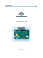
ScratchDuino.Lab
St.Petersburg
2015
JSC “Tyrnet”
ScratchDuino.Lab
St.Petersburg
JSC “Tyrnet”
2015
Printed by the order of
JSC “Tyrnet”
Reviewer:
— Professor Irina B. Gotskaya, EdD, Chairperson of IT Education Methodology
Dept. at Herzen State Pedagogical University (St.Petersburg)
Elena A. Vostrikova
ScratchDuino.Lab: User Manual / Elena A. Vostrikova, Leonid S. Zakharov,
Ekaterina A. Lvova. — St.Petersburg: Reprographics Center of JSC “Tyrnet”,
2015. — 54 p.
This User Manual explains how to operate ScratchDuino.Lab, which is an electronic device with built-in sensors of sound and light, an adjustable resistor,
and interface to attach extra sensors.
The Manual contains the following information:
1. Instructions on installing the software for the three major operating systems
(OS).
2. List of the components in the box, the methods for sensors testing and calibration. Essential information about the programming language Scratch needed for the work.
3. Examples of working scripts to use with the sensors.
4. Instructions on registering and placing individual projects at the portal
wiki.scratchduino.com, as well as the opportunities of children’s and adults’
cooperation within the framework of the festival “ScratchDuino Libre Robotics”.
© JSC “Tyrnet”, 2015
Table of Contents
Installing the Software for ScratchDuino.Lab ..................................................... 4
Windows OS Family ........................................................................................ 4
Linux OS Family ............................................................................................... 8
Mac OS Family .............................................................................................. 12
Components of the Kit ..................................................................................... 13
Sensors Testing and Calibration .................................................................... 15
Basic Concepts of Scratch ............................................................................. 19
Basic Algorithms of Scratch ........................................................................... 22
Projects To Make Use of the ScratchDuino.Lab Components ........................... 28
Buttons ......................................................................................................... 28
Slider............................................................................................................. 29
Sound Sensor ................................................................................................ 30
External Temperature Sensor ........................................................................ 33
External sensors ............................................................................................ 35
Promoting the Community of the Like-Minded ................................................ 38
Wiki Portal of Project ScratchDuino: Signing up ............................................ 38
wiki.scratchduino.com: Uploading a Project ................................................. 44
Rules on Discussing the Projects at wiki.scratchduino.com........................... 47
Information Sources ......................................................................................... 50
Appendix .......................................................................................................... 51
Statutes of ScratchDuino Libre Robotics Festival ........................................... 51
4
Installing the Software for ScratchDuino.Lab
Windows OS Family
To work successfully with ScratchDuino.Lab under Windows, it is
necessary to install at least the visual programming environment for
Scratch and Arduino UNO driver. In addition, advanced users might
want to install along with the Arduino IDE the Arduino developer’s
environment as well.
The software can be obtained from:
the CD, shipped with ScratchDuino.Lab;
the file server of the project — http://files.scratchduino.ru/;
the official developers website.
Installation from the CD or from the File Server of the Project
How to install Scratch: run the installation file ../windows/Scratchduino.exe
from CD or or download and run the installation file from the file server —
http://files.scratchduino.ru/Software/Windows/Scratchduino.exe
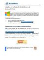
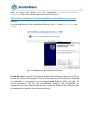
The Installation Wizard will ask you to choose a language — choose English,
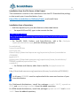
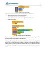
then press Ок, Next, and Install. In a few seconds, two icons will appear at the
desktop (or in the application list of the Start button, depending on individual
setup)— Scratch and Scratchduino Robot (Fig. 1).
Fig. 1. The icons to appear.
To operate Scratchduino.Lab, the Scratch software is intended! To launch, click the Cat icon.
5
How to install the driver: run the executable../windows/ScratchDuino_
drivers.exe from CD or download it from the file server —
http://files.scratchduino.ru/Software/Windows/ScratchDuino_drivers.exe.
and run.
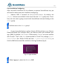
In the dialog boxes of the Installation Wizard, click Yes, then Next, Install, and
Finish.
Fig. 2. Dialog boxes of Installation Wizard.
A note for users: You will not find any Arduino IDE software either on the CD or
on the file server of the project. This is intentional, as with Arduino IDE installed
it is possible to reprogram the pre-programmed Arduino UNO cartridge. To
avoid confusions, we do not recommend Arduino IDE installation for
inexperienced users. Advanced users can install the Arduino IDE software from
the developer’s website (see the next section).
6
How to Install the Software from the Developer’s Website
1. Download the installer for Scratch 1.4 from the developer’s website:
http://download.scratch.mit.edu/ScratchInstaller1.4.exe.
Run the installer, choose English as installation language and follow
the instructions of Installation Wizard. After a successful installation
you’ll see the Scratch icon (Cat).
2. Download the fresh version of the Arduino IDE software from the developer’s website https://www.arduino.cc/en/Main/Software and follow the installation instruction — https://www.arduino.cc/en/Guide/Windows.
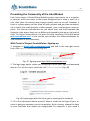
How to Connect ScratchDuino.Lab via USB Cable
Plug the USB cable, shipped along with ScratchDuino.Lab, into the USB port of
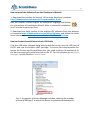
the PC and into the Arduino UNO cartridge. To ensure the communication between the Scratch and ScratchDuino.Lab, you need to know the number of serial port connecting ScratchDuino.Lab to the PC. For this purpose, go to Device
Manager, usually found at Control Panel.
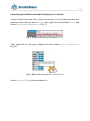
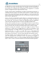
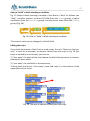
Fig. 3. A snapshot of Device Manager window, showing the number
of serial (COM) port, to which the device is connected automatically.
7
Remember the number of the COM port! It is the port you’ll need to select
in Scratch. In Fig. 3, Arduino UNO matches the port COM9.
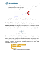
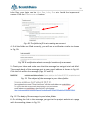
Connecting Scratchduino.Lab and Selecting a Port in Scratch
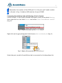
Launch Scratch. In the Scratch window that opens, select a blue block Sensing,
then right-click on the block Sensor and select show ScratchBoard watcher
(Fig. 4).
Fig. 4. Right-click menu of the Sensor block.
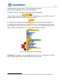
Right-click on the grey background and choose select serial/usb port (Fig. 5).
Fig. 5. Right-click menu of the ScratchBoard.
Select the port, to which ScratchDuino.Lab is connected, in the drop-down list.
8
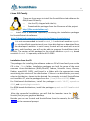
Linux OS Family
There are three ways to install the ScratchDuino.Lab software for
GNU/Linux OS family:
Use the CD, shipped with the kit;
Download the packages from the file server of the project
http://files.scratchduino.ru/;
Install from a dedicated repository containing the installation packages
for ScratchDuino.Lab software:
http://download.opensuse.org/repositories/home:/scratchduino/.
It is not recommended to install scratch_1.4 and virtual machine squeakvm via the official repositories of your Linux distribution or download from
the developer’s website. In such a case, Scratch will not work with a serial
port, and therefore, you will not be able to program ScratchDuino.Lab in
Scratch. The version of the package for the virtual machine squeak-vm, based
on which Scratch 1.4 operates, must be 4.0.3-2202.
Installation from the CD
The packages for installing the software under an OS of Linux family are on the
CD in the ../linux folder. Installation packages are built for some of the most
common Linux distributions (RHEL/CentOS, Fedora, Scientific Linux, Ubuntu,
Debian, openSUSE, SLED), and found in a folder with the appropriate name
mentioning the version of the distribution. If there is no distribution you need,
select a distribution, closest to the desired. For example, to install ScratchDuino
on Linux Mint 17, use the packages from the ../linux/xUbuntu14.04/ folder.
For Deb-based distributions, install the packages scratch 1.4.0.7, squeak-vm
4.0.3, and squeak-plugins-scratch.
For RPM-based distributions, install the packages squeak-vm 4.0.3 and scratch
1.4.0.7.
After the successful installation, you will find the launcher icons for
Scratch (Cat) at your graphical desktop.
Besides you can run Scratch and ScratchDuino from the console; for this, type
scratch at the command prompt.
9
Installation from the File Server of the Project
The installation is similar to the installation from the CD. Download the packages that match your Linux distribution, from
http://files.scratchduino.ru/Software/Linux/, and install them.
Installation from a Repository
Add the repository for your distribution as described below:
for openSUSE and SLE, type in the console the line
$ sudo zypper addrepo
http://download.opensuse.org/repositories/home:/scratchduino/XXXXXXX/
ScratchDuino
for CentOS, RHEL, Fedora, and ScientificLinux, add a file /etc/yum.
repos.d/scratchduino.repo, with the following contents:
[scratchduino]
name=ScratchDuino
type=rpm-md
baseurl=http://download.opensuse.org/repositories/home:/scratchduino
/XXXXXXX/
gpgcheck=1
gpgkey=http://download.opensuse.org/repositories/home:/scratchduino/
XXXXXX/repodata/repomd.xml.key
enabled=1
for Debian and Ubuntu, add a line to the file /etc/apt/sources.list:
deb
http://download.opensuse.org/repositories/home:/scratchduino/XXXXXXX/ /
In all cases, XXXXXXX must be replaced with the name and version of your
Linux distribution.
For Deb-based distributions, install the packages scratch 1.4.0.7, squeak-vm
4.0.3, and squeak-plugins-scratch from the added repository.
For RPM-based distributions, install the packages squeak-vm 4.0.3 and scratch
1.4.0.7 from the added repository.
10
Post-Installation Configuring
After successful installation of the software to operate ScratchDuino.Lab, you
will need to make some post-installation configuring.
Arduino UNO is accessed via /dev/ttyACM<номер>. By default, the
/dev/tty* devices are available to the users from the dialout group only. Therefore, the user who is going to work with ScratchDuino.Lab must belong to the
dialout group.
Add the user to the dialout group!
If your Linux distribution is either Ubuntu 12.04 and later or an Ubuntubased distribution (for example, Mint), you need to check your windows manager (WM). By default, it is Compiz. Unfortunately, Compiz can cause conflicts
with Scratch. That’s why it is recommended to install the package gnomesession-fallback (for Ubuntu 14.04 and later — gnome-session-flashback), so
that the WM choice would be available at the login window (Fig. 6).
Fig. 6. Login window.
When logging in, select the Metacity WM!
11
Connecting ScratchDuino.Lab and Selecting a Port in Scratch
Launch Scratch from the GUI or from the console. In the Scratch window that
pops up, select the blue block Sensing, then right-click on the block Sensor and
select show ScratchBoard watcher (Fig. 7).
Fig. 7. Right-click menu of the block sensor.
Then right-click on the grey background and choose select serial/usb port
(Fig. 8).
Fig. 8. Right-click menu of the ScratchBoard.
Select /dev/ttyACM0 in the drop-down list.
12
Mac OS Family
To install the software for Mac OS, it is possible to use the CD,
shipped with ScratchDuino.Lab, or to download the installation
files from the file server of the project.
On the CD, the installation file is in the ../mac/Scratch.dmg
folвer.
The link to download from the file server is
http://files.scratchduino.ru/Software/Mac/Scratch.dmg.
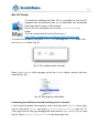
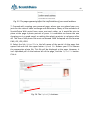
To install the software, just open Scratch.dmg and drag the Scratch folder into
the Application folder (Fig. 9).
Fig. 9. The window looks like that.
Open Application in a file manager, go to the Scratch folder, and run the executable (Fig. 10).
Fig. 10. Running the executable.
Connecting ScratchDuino.Lab and Selecting a Port in Scratch
In the Scratch window that appears, select the blue block Sensing, then rightclick on the block Sensor and select show ScratchBoard watcher (see Fig. 7).
Then right-click on the grey background and choose select serial/USB port (see
Fig. 8). Select /dev/cu.usbmodem1411 in the drop-down list.
13
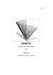
Components of the Kit
ScratchDuino.Lab (“Digital Laboratory”) is intended for laboratorial and illustrating experiments, research projects of the students, and hands-on training at
the IT-classes and the lessons on natural sciences in primary and secondary
schools, 5–11 grades.
The equipment includes:
Arduino UNO microcontroller with the options of standalone operation
and cinnection to a PC with monitor;
built-in sensors (see Fig. 13);
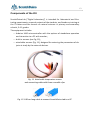
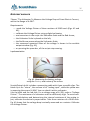
attachable sensors (Fig. 11), designed for metering the parameters of objects at study by the external devices.
Fig. 11. Attachable temperature sensor
and connecting cable with three crocodile clips.
Fig. 12. 180-cm-long cable to connect ScratchDuino.Lab to a PC.
14
10
9
8
1
7
2
3
4
6
5
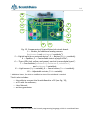
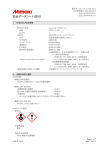
Fig. 13. Components of ScratchDuino.Lab circuit board:
1— Sockets for additional analog sensors
(resistance-A and resistance-B variables1);
2 — Digital input for an external device*; 3 — Button (Button variable);
4 — Speaker; 5 — Controllable matrix of eight LEDs*;
6 — Three LEDs (red, yellow, and green), each at its own digital input*;
7 — Four buttons (resistance-A, resistance-B, resistance-C,
and resistance-D variables);
8 — Light sensor (Light variable); 9 — Sound sensor (Sound variable);
10 — Adjustable resistor (Slider variable).
* Additional items, for which a modified version of ScratchBoard is needed.
The kit also includes:
the cable to connect the ScratchBoard to a PC (see Fig. 12);
a CD with the software;
User Manual;
written guarantee.
1
The said variables are used in the Scratch programming language, which is considered later.
15
Sensors Testing and Calibration
To be able to compose the programs, it is important to study the response of
the sensors and the values taken by the buttons of ScratchDuino.Lab. Despite
their being standard, the sensors in different kits of ScratchDuino.Lab can have
their own individual ranges of sensitivity.
Table 1. Sensitivity Ranges and Values Taken by the ScratchDuino.Lab Buttons
Sensor or button (name of the variable)
Min Max
Light sensor (Light variable)
12
98
Sound sensor (Sound variable)
23
100
Adjustable resistor (Slider variable)
0
100
false
true
0
100
0,6
22,5
Black button (Button variable)
Four buttons (resistance-A, resistance-B, resistance-C,
and resistance-D variables)
Temperature sensor
(when connected, uses the resistance-A variable)
Calibration of Light Sensor
To calibrate a light sensor, a meter of illuminance is used. In our case, it is digital luxmeter LX101. The measurements shown in Table 2 and in Fig. 14.
1
3
11
22
37
42
53
63
75
83
92
220
320
440
562
Luxmeter
LX-101, lx
Light
sensor
110
Table 2. Relation between the Meterage of ScratchDuino.Lab Light Sensor
and Luxmeter LX-101
12
47
60
65
67
67
69
70
70
71
72
73
75
82
86
90
16
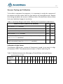
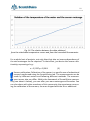
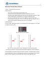
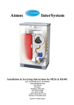
Fig. 14. Area of linear dependency (confidence range)
between the Luxmeter LX-101 and the light sensor of ScratchDuino.Lab
meterage curves.
Using the Luxmeter LX-101 user manual’s guidelines on recommended level of
luminance at working places (Fig. 15), it is possible to assume that the built-in
light sensor of ScratchDuino.Lab can be with great confidence used as a
luxmeter at a luminance of up to 100 lx calculated by Formula 1. This formula is
obtained as per a trend line (approximation of the function) for the light sensor
values from 12 to 73.
y = x - 15,62
(1)
confidence range of the sensor
Fig. 15. Recommended luminance at working places
and the confidence range of ScratchDuino.Lab light sensor.
17
Calibration of Sound Sensor
The measurements are made in a room at complete silence. In this case the
sensor indicates the value 23. The natural sounds (voice, music etc.) correspond to a range of 60–80. A maximum of 100 can be achieved when you make
a vigorous breathing-out into the sensor. To identify the functional dependence
of the sensor sound in decibels (dB), you need to use a digital phonometer.
Methods of measurements and the derivation of a formula are similar to those
described for the calibration of light and temperature sensors.
The Values Taken by Adjustable Resistor Slider
At the leftmost position it reads as 0, at the rightmost position — as 100.
The Values Taken by Black Button
On pressing this button, its value toggles from false to true and vice versa.
The Values Taken by Coloured Buttons
On pressing any of these buttons, its value toggles from 0 to 100 and vice versa.
All the buttons have a usual group of contacts: a couple of fixed contacts and a
movable contact between them. At the movable contact, a rod is fastened that
protrudes out of the case of the circuit board.
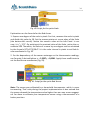
Calibration of Temperature Sensor
To calibrate a temperature sensor, we are going to measure the temperature
of water being continuously heated up, and we put the readings, taken from a
thermometer and from a sensor panel, into Table 3. Make a graphical plot
based on the data of the table (Fig. 16).
Table 3. Relation between the Values Taken from the Attachable Temperature
Sensor and the Household Thermometer
Термометр,
градусы
Датчик температуры, ед.
0
5
10
15
20
25
30
35
40
45
50
0,6
2,2
4,3
6,7
9
11,1
13,7
15,8
17,9
20,2
22,5
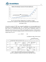
The trend line (approximation of the function) shows that the relation between
the values taken from the attachable temperature sensor and from the household thermometer is linear and can be expressed by Formula 2:
y = 0,4497x - 0,4165
(2)
18
Fig. 16. The relation between the data obtained
from the attachable temperature sensor and from the household thermometer.
For a whole host of projects, not only direct but also an inverse dependency of
the said meterages can be required. To that effect, just derive the inverse relationship, expressing х by у:
х = 2,2237у + 0,9261
(3)
Sensors calibration Calibration of the sensor is a specific area of educational
research performed using the ScratchDuino.Lab. The measurements can be
made by different meters and following different methods. The measurement errors also can differ. Within the framework of ScratchDuino community (see about it below), you can offer your own meterage and formulas. You
can also share with other members of this community the experience concerning the calibration of the sensors, the ones shipped with the kit or additional.
19
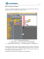
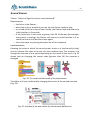
Basic Concepts of Scratch
Scratch is a computer model of the real world. Its environment with the items
of graphical user interface (GUI) is shown in Fig. 17.
1
2
3
4
5
6
7
8
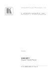
Fig. 17. The Scratch environment:
1 — Info Panel; 2 — the Block Palette (groups of commands);
3 — the Script Area; 4 —Control group; 5 — the Actor (sprite);
6 — background of current Stage; 7 — the Sprites Panel; 8 — the Stage area.
The world of Scratch consists of many objects (the word “object” stems from
Latin objectum, which means a thing) populating a common space. The objects
are anything that exists in the nature: people, animals, wind, snow, tree,
sun, letters, ice-cream, candies and all.
The objects can also be Actors to implement the algorithms.
20
An algorithm is an exact, step-by-step instruction determining the behaviour of
the Actor(s) that brings the data (taken, for example, from the ScratchDuino.
Lab sensors) to a required result. Development of an algorithm is a creative
process. An algorithm can be represented as a script.
Scripts in Scratch and in ScratchDuino are made of ready blocks-commands, resembling the bricks of Lego. This syntax is quite intuitive. To make a script, you
have to join several blocks (just snap them together in the Script Area). The
blocks and the order they follow each other are important, because they define
what an Actor is going to do.
Actors in Scratch are depicted by sprites (Sprite is a supernatural creature, an
elf), while the space where the events are happening is a Stage. The Stage can
be an Actor too. The stories in Scratch are described using the algorithms.
There are only two kinds of Actors in Scratch: the Stage and the sprites.
Sprites, either created by the users, or downloaded or found in a sprite library,
are the Actors that operate within the project. Many projects include, as a minimum, one sprite that can move around the project screen, unlike the stage.
Except for running the commands, a sprite can change its costume. The appearance of a sprite can be changed directly or with the commands in the
scripts editing area. To change a costume, you need to go to the Costumes tab,
found next to the Scripts and Sounds tabs. The Costumes tab contains the
whole list of costumes, and the costumes can be modified or imported from a
sprite library or from your PC. You can create and add a new costume as well.
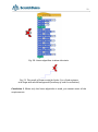
The Stage includes a set of images found under the Backgrounds tab (Fig. 18),
which are background for the sprites’ actions. On launching the program, a
background image is ready: it is a white rectangle, 480-pixel wide and 360-pixel
high. A “pixel” is a dot, a minimal component of rasterized computer graphics.
Fig. 18. The Backgrounds Tab.
21
The command set for the sprites consists of 125 commands, while for the stage
there are 85 of them. This set allows for the implementation of a vast variety of
algorithms. All the commands are found at the top-left pane of the program
window (the Block Palette), distributed into eight groups. The groups are highlighted with different colours: Motion, Looks, Sound, Pen, Control, Sensing,
Operators, and Variables.
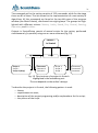
Projects in ScratchDuino consist of several scripts for the sprites, performed
simultaneously (in parallel) using one or more costumes (Fig. 19).
PROJECT
in Scratch
Sprite 1
Stage
Sprite...
Спрайт …
- Script 1
- Script …
- Script 2 (Stop)
- Costume 1
- Costume 2
- Costume...
- Script 1
- Script 2
- Script …
- Costume 1
- Costume 2
- Costume...
Fig. 19. The structure of a project in Scratch.
Highlighted is the mandatory part.
The rest depends on the author’s design.
To describe the projects in Scratch, the following pattern is used:
theme;
requirements to meet;
description of the project progressing and/or explanations for the script;
the picture of the script.
22
Basic Algorithms of Scratch
The algorithms can be divided into three kinds as of their structure: linear,
branching, and loops.
Linear algorithm is such one, for which all the commands are done one after
another and only once. Its script is a sequence of blocks, following from top to
bottom in the order of their performing.
Theme: “The Crab Draws the Stairs”.
Requirements:
the Actor is the Crab;
the drawing is made like in an animated cartoon;
an easy option to change the number of stair-steps and their size is provided;
the script runs if the value of Slider variable is greater than 50.
Implementation of the project “The Crab Draws the Stairs”
using a linear algorithm
We have to teach our Crab to draw the stairs. The Crab lives in a rectangular
field of a size 480×360 pixels and knows how to locate a place in the field by its
coordinates2. The Crab can make a prescribed number of moves; wait; and
point in the directions left and right by 0, 90, and 180 degrees. The Crab has a
pen that leaves a line when put down. A script for the Crab is shown in Fig. 20.
As per this script, the Crab draws 3 steps (Fig. 21). The script starts running on
pressing the “up arrow” key.
If you use a purely linear algorithm:
the process of “building” the stairs is not visible, but the picture appears
instantly;
changing the number of stair-steps needs to make the script longer and
to edit numeric values in each block, so this method cannot be called
easy;
the requirement concerning the Slider cannot be met.
2
It is reasonable to start studying Scratch since the 5th grade, as the students have to be aware of some mathematical notions, such as “coordinate plane”, “positive and negative numbers”, “decimal fraction”, “degree
measure of angles” etc. However, simple projects can be implemented in primary school as well.
23
Fig. 20. Linear algorithm to draw the stairs.
Fig. 21. The result of linear script for Sprite 1 in a Crab costume
at a Stage with white background (courtesy of crab1-a collection).
Conclusion 1. When only the linear algorithm is used, you cannot meet all the
requirements.
24
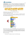
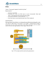
Loop algorithms. A loop is a series of commands to be repeated until a
specified condition becomes true. Thanks to the operators controlling the loop,
the script can be done much shorter. Scratch provides the blocks for four kinds
of loops: unconditioned (endless); with a counter; with a pre-condition; and
with a post-condition (Fig. 22).
Fig. 22. Loops in Scratch.
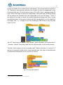
Implementation of the project “The Crab Draws the Stairs”
using a linear algorithm and a loop
It is easy to notice that in Fig. 20, a set of commands is repeated: make 60
moves, point in the direction 0° (upwards), make 40 moves, point in direction
90°. That means we can use a loop.
Fig. 23. A loop.
Notice that the script in Fig. 23 is shorter than in Fig. 20, and the Crab has
drawn 5 stair-steps (Fig. 24). Now it will be enough to change the value in the
repeat box, and you will have as many stair-steps as you like. If we change the
number of the moves (the height of a stair-step) from 40 to 20 in just one
block, all the stair-steps will change.
When we use a loop:
the process of “building” the stairs is not visible anyway;
25
we have managed to meet the requirement about easily changing the
number and the size of the stair-steps;
the requirement concerning the Slider cannot be met yet.
Fig. 24. The result of script with a loop for Sprite 1 in a Crab costume
at a Stage with white background (courtesy of crab1-a collection).
Conclusion 2. When only the linear algorithm and a loop is used, you cannot
meet all the requirements of the project “The Crab Draws the Stairs”.
Branching algorithms. An algorithm is called branching if it has several options
to choose for a further action. The choice can be simple (in case of two alternative options) or complicated (when there are more than two options) (Fig. 25).
Fig. 25. A complicated choice.
The moment of a choice is called the branching point. Branching is one of the
three basic structures of algorithms (along with the linear flow of commands
and the loop). All the programming languages have special operators (or commands) — conditional operators, to implement an action depending on a stated condition. Scratch has three conditional operators in its Control group:
complete branching (IF-THEN-ELSE), incomplete branching (IF-THEN), and
pause (WAIT UNTIL) (Fig. 26).
Fig. 26. Conditional operators in Scratch.
26
Implementation of the project “The Crab Draws the Stairs”
using a linear algorithm, a loop, and a branching
As shown in Fig. 27, the ready script (Fig. 23) was added by:
1) two blocks of pauses
, enabling you to see (like in an ani3
mated cartoon ) the process of drawing the stairs;
2) a block of incomplete branching
, that checks the value of the Slider variable from the connected ScratchDuino.Lab. In accordance with the specified condition, the script runs if the Slider rests at the right-hand side of its
“lane”, that is, the value of the Slider variable is greater than 50.
Fig. 27. An algorithm with branching.
Conclusion: The project can be implemented in full only in case when all three
kinds of algorithms (linear, loop, and branching) are used.
3
Such delay, convenient for human eye, belongs to the methods of developing the projects with animation.
27
How to “build” a block checking a condition
Fig. 27 shows a block checking a condition. Such block is “built” as follows: you
“drag”, one after another, the block IF-THEN (from the Control group), a logical
expression (from the Operators group), and the sensor value (from the Sensing
group) (Fig. 28).
Fig. 28. How to “build” a block checking a condition.
The numeric value can be changed in the Edit field.
Editing the script
If you need to remove a block from a ready script, the rule “Detach at the bottom” is used. As an example, to remove a block from the script in Fig. 29 (the
block is marked by a red arrow), you have to:
1) “tear away” the piece of the script below the block that you want to remove,
putting this piece aside;
2) “tear away” the said block in the same way;
3) bring back the former “torn away” piece and snap it to the bottom of the
upper piece of the script.
Fig. 29. The way to remove a block from the script.
28
Projects To Make Use
of the ScratchDuino.Lab Components
Buttons
ScratchDuino.Lab allows you to operate virtual Actors. Consider using the buttons (resistance-A, resistance-B, resistance-C, and resistance-D variables).
Theme: “The Cat’s Journey”.
Requirements:
for the “journey”, an appropriate picture is set as a background;
on pressing the coloured buttons of ScratchDuino.Lab, the Cat must
move rightwards, leftwards, upwards, and downwards;
the script stops on pressing the space bar of the keyboard.
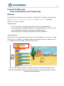
Implementation
Click on the Stage and select the Background tab. Select New background and
click the Import button. A window with ready images will open. Select the Nature folder and in this folder, select the file desert.
Fig. 30. Two sample scripts to control a sprite in a Cat costume (file cat1-a)
with the ScratchDuino.Lab keys. Framed is the first script that stops all scripts
on pressing the space bar.
29
Slider
Theme: “Varying the Speed of the Ball by Slider”.
Requirements:
the Actor is the Ball;
launching the script, the Ball starts to move horizontally “back and
forth”, bouncing from the walls within the Stage;
the speed of the Ball is controlled with Slider;
the script stops on pressing the space bar of the keyboard.
Implementation
The key idea of the solution is to change the coordinate step along the х axis.
The effect of bouncing at the border of the Stage is implemented through a
comparison of the current coordinate of the Ball (х position) and the coordinates of the left and right borders of the Stage: 200 and -200.
Fig. 31. The script and the result of its performance.
30
Sound Sensor
Theme: “Hop on a Signal (a clap or a word uttered)”.
Requirements:
the Actor is the Dancer;
when the script is launched, you can see the Dancer ready to hop;
on a loud shriek (or a clap of your hands), the Dancer hops and returns to
initial position in 3 seconds;
if the noise level in the room is greater than 24 all the way (for example,
some music is playing), the Dancer still returns to initial position in 3 seconds (to have a rest) and then hops again;
the script stops on pressing the space bar of the keyboard.
Implementation
Knowing the value at which the sound sensor reacts to a loud sound (a clap),
you can choose the value to be put into the condition box. The solution is to
change the costume of one sprite depending on the result of the check. Fig. 32
shows that on changing the sensor value (greater than 24) the costume is
changed.
Fig. 32. The script and the result of its performance.
The effect of a hop is achieved by changing the center of the second costume
(Fig. 33).
Fig. 33. Location of the new center for the costume ballerina-d.
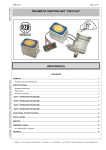
31
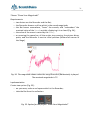
Theme: “Show Your Magnitude!”
Requirements:
two Actors are the Recorder and the Bat;
the Recorder draws a red line which is the sound magnitude;
the Bat hovers somewhere, “hears” the sounds, and “remembers” the
maximal value of the Sound variable, displaying it in a cloud (Fig. 34);
the value of the move is varied by the Slider;
on pressing the space bar, all the scripts stop running, the picture disappears, and the Recorder is sent to initial position (bottom-left corner of
the Stage).
Fig. 34. The magnitude shown when the song Ohne dich (Rammstein) is played.
The maximal magnitude is 72.
Implementation
Create two sprites (Fig. 35):
on your own, make a red square which is the Recorder;
take the Bat from the collection.
Fig. 35. Sprites for the project “Show Your Magnitude!”
32
As per our study of the sound sensor (see above), its minimal value at silence is
23. Therefore, you need to subtract this number so that the magnitude in the
field would be zero. The sensitivity range is 23 to 93, that is, approximately 70
units, while the Stage to show the magnitude is 360-pixel high. Dividing 360 by
70, we obtain the multiplier for the magnitude to fit into the Stage. “-150” is
the value of the step to move the picture downwards along the y axis, as the
coordinate center of the sprite (a point of (0;0) coordinates) is in the middle of
the Stage. The Slider’s range is 0 to 100. Dividing by 200 allows to vary the step
from 0 to 0.5.
Fig. 36. Two scripts for Sprite 1: one “draws”, while the other, if the space bar is
pressed, “erases” the picture and sets the Self-Recorder to the initial position.
The Bat’s task requires to use a variable max4. Before the loop, it is set to 0. If
within the loop the sound sensor value exceeds zero, the value of variable max
is updated and displayed in the cloud for 1 second.
Fig. 37. Script for Sprite 2.
4
The variables are created in the Variables group.
33
External Temperature Sensor
Theme: “Household Thermometer”.
Requirements:
Two Actors are the Scale and the Red Arrow;
the Scale of the household thermometer is placed on the left;
the Red Arrow moves along the Scale, while on the left a numeric value
of the temperature is displayed in an output window (Fig. 39);
you have to determine the size of one degree in pixels at the Scale.
on pressing the space bar, all the scripts stop running, and the Scale is
sent to initial position (bottom-left corner of the Stage).
Implementation
On your own, make both sprites: the temperature Scale ranging 0 to +50 and
the Red Arrow (Fig. 38).
Fig. 38. Sprites for the project.
Fig. 39. Three views of the screen, showing the results of the project.
You can see a dynamic change of the measured temperature of the ambience.
We are going to make two scripts for Sprite 2 (Scale): a standard stop on pressing the space bar, while on launching the project (on pressing the “up arrow”
key) the Scale is placed in the bottom-left corner of the Stage (Fig. 40).
34
Fig. 40. Script for the sprite Scale.
Explanations on the formula for the Red Arrow.
1. Express one degree of the scale in pixels. For that, measure the scale in pixels
and divide this value by 50. Set the mouse pointer at a zero value of the Scale
(the bottom-left corner). Notice the numeric value at the Info Panel. In our
case, it is “– 175”. On pointing at the maximal value of the Scale, notice the coordinate 175. Therefore, the value of a move by one degree can be calculated
by the formula (175+175)/50=7. It is the scale interval in pixels to set Red Arrow coordinates in Fig. 39.
2. For the dependency of the sensor meterage on the thermometer readings,
use Formula 2 derived before: х = 2,2237у + 0,9261. Apply these coefficients to
set the Red Arrow coordinates (Fig. 41).
Fig. 41. Script for the sprite Red Arrow.
Note: The sensor was calibrated by a household thermometer, which is never
too exacting. That’s why during the project implementation it was noticed that
the sensor showed the temperature value higher than our own senses suggested. You have to calibrate your temperature sensor using a thermometer of a
better precision.
35
External sensors
Theme: “The Voltmeter To Measure the Voltage Drop at Direct Electric Current,
within the Range of 4–20V”.
Requirements:
made the Voltage Divisor of three resistors of 91KΩ each (Figs. 42 and
43);
calibrate the Voltage Divisor using a digital voltmeter;
use two actors in the script: the Voltmeter Scale and the Red Arrow;
the Voltmeter Scale is placed on the left;
the Red Arrow moves along the Voltmeter Scale;
the measured numerical value of the voltage is shown in the variable
output window (Fig. 42);
on pressing the space bar, all the scripts stop running.
Implementation
Fig. 42. Measuring the battery voltage
using the Device, and a view of the screen.
ScratchDuino.Lab kit includes a connecting cable with three crocodile clips. The
black clip is for “minus”, the red one is for “analog input”, while the yellow one
is powering the sensor (4.36V). You can check it with a voltmeter.
Use the black and the red clips. For a voltage range of 4–20V, make a “Voltage
Divisor”. The resistance of a voltmeter must be sufficiently high. To avoid complicated calculations and determining the internal resistance of the analog input, calibrate the device by experiments. Take three resistors of a 91KΩ each.
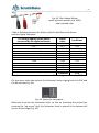
Fig. 43 shows that the voltage drop is actually measured on a resistor. Calibrate
the Voltage Divisor.
36
Fig. 43. The Voltage Divisor
made of three resistors of a 91KΩ
and crocodile clips.
Table 4. Relation between the Values of the ScratchDuino.Lab Sensor
and the Digital Voltmeter
The voltage applied to the device
measured by the digital voltmeter
Sensor
value
Coefficient
3.94
4.95
5.9
6.97
8.03
9
10.02
11.08
12
13.02
14.03
15.77
18.57
23.4
28
33
38.03
42.72
47.51
52.49
56.9
61.68
66.57
74.7
4.71
4.73
4.75
4.73
4.74
4.75
4.74
4.74
4.74
4.74
4.74
4.74
AVERAGE
4.74
As Table 4 shows, the dependency is linear. The average coefficient is 4.74.
On your own, make two sprites: the Voltmeter Scale ranging from 0 to 20V and
the Red Arrow (Fig. 44).
Fig. 44. Sprites for the project.
Make the script for the Voltmeter Scale, so that on launching the project (on
pressing the “up arrow” key) the Voltmeter Scale is placed in the bottom-left
corner of the Stage (Fig. 45).
37
Fig. 45. Script for the sprite Scale.
Explanations on the formula in the script for the sprite Red Arrow:
place the Arrow closer to the Scale picture;
use variable u for the measured voltage;
place the Arrow at the y axis according to the variable value;
show the variable.
Fig. 46. Script for the sprite Red Arrow.
Test the Voltage Divisor. Measure the battery voltage as shown in Fig. 42. The
dynamic changes of the value will be displayed.
Note: Using this device, you can measure a voltage of 0 to 4V. However, your
meterage is not going to be very precise. At the same time, measuring a voltage of 0 to 4V is not difficult, as no divisor is needed: it is enough to connect a
power source of up to 4V to the black and the red clips. It is important to make
the calibration following the above-mentioned methods and make a separate
script.
38
Promoting the Community of the Like-Minded
Each lucky owner of ScratchDuino.Robokit project constructor, be it a teacher
or parents, with time starts to feel some disappointment: what is next? As a
rule, their ideas of creating new projects quickly come to an end. However, if
there is a place where you can show off your projects and get them commented, or watch the ready projects of other people, your creativity gets a new impetus. The Internet communities are just about that, and they resemble the
thematic clubs where there are no differences caused by the age or the level of
skills. For Project ScratchDuino, the place for such socializing is the Wiki portal
wiki.scratchduino.com. In this section, we consider the recommendations for
new members of this community.
Wiki Portal of Project ScratchDuino: Signing up
1. Navigate to http://wiki.scratchduino.com and and in the top-right corner
find a link Log in / create account (Fig. 47).
Fig. 47. Signing up at http://wiki.scratchduino.com.
2. The login page opens, where you are going to enter your login and password
later on. For the first time, select the link Create an account (Fig. 48).
Fig. 48. Login page (with the link to get to creating of an account).
3. Fill in the information about yourself. Keep in mind that the login of your account is going to represent you at the website. By this reason, choose the login
as your nickname that makes you recognizable. For example, if your name is
39
John Doe, your login can be John Doe, John, Doe etc. Avoid the impersonal
names. Click the Create account button.
Fig. 49. The fields to fill in at creating an account.
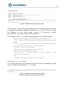
4. If all the fields are filled correctly, you will see a notification similar to shown
in Fig. 50:
Fig. 50. A notification about successful creation of an account.
5. Check your Inbox and make sure that the message has not got into Junk Mail.
The sample body of the message sent to your email address is shown in Fig. 64.
Click the link within the message (Figs. 51 and 52).
Fig. 51. The subject of the message in your Inbox folder.
Fig. 52. The body of the message in your Inbox folder.
6. On clicking the link in the message, you get to the project website at a page
with the wording shown in Fig. 53:
40
Fig. 53. The page appearing after the confirmation of your email address.
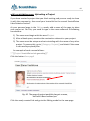
7. Proceed with creating your personal page, where you can upload your projects for the sake of ideas exchange and discussions. Many of the members of
ScratchDuino Wiki portal have never met each other, so it would be nice to
place at the page a photo portrait of yours. It is advisable to choose the one
showing you in a good mood, as making the robotic projects is a pleasure after
all! The size of the photo file must not exceed 2MB. Accepted are file formats
PNG, GIF, JPG, JPEG.
8. Select the link Upload file in the left menu of the portal. At the page that
opens find and click the upper button Upload file. Browse your PC to choose
the appropriate photo file. This file will be displayed at the page. However, it
isn’t uploaded yet! At the bottom left of the page, find the Upload file button.
Click it.
Fig. 54. The Upload file buttons.
41
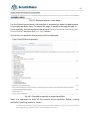
9. As a result, the page with the uploaded file will look
like shown in Fig. 55. Скопируйте имя страницы Copy
the title of the page. In our example it is File:11-042015.jpg.
10. Now, create the proper page of ScratchDuino
community member at the portal http://wiki.
scratchduino.com. Take notice that your account name
at the top of the page is highlighted red (Fig. 56). It
means that the page has got a title, but isn’t created yet!
Click on the account name.
Fig. 67. The name of
the page that bears
your photo.
Fig. 56. From now on, your page has a title, but is not created so far.
11. You'll get to the page with the message shown in Fig. 57.
.
Fig. 57. The page where you are offered to create a personal page.
Select the link Edit this page.
12. A window of a text editor will open.
Fig. 58. Your page in the Editing mode.
For members of the community, a template of personal page is provided. To
create a page, it is enough to enter the phrase {{subst:Template:Personal user
page}} very carefully (without any mistake) and click the Save page button. As a
result, your page will be created with a standard content (Fig. 59).
42
Fig. 59. Standard content of your page.
13. Go to the Edit tab. Fill in the mandatory lines at Personal page of Community member ScratchDuino. Replace the filename Logo-1024be1-300x54.png with
the filename of your own photo. Instead of “Community member
ScratchDuino”, type in your Name and Surname etc.
For example, in the Editing mode a personal page can be made as follows:
[[File:11-04-2015.jpg|thumb|100px|left|Elena Vostrikova]]
'''City:''' [https://en.wikipedia.org/wiki/Novokuznetsk Novokuznetsk]
Russia
'''School:''' [http://ipknk.ru municipal autonomous educational institution of additional education "Training Institute"]
'''Position:''' department manager
'''My contribution to the prоject ScratchDuino:'''
[[Project ScratchDuinoLab gameship]]
'''My discussion of creative projects of other members of the
ScratchDuino community'''
null
[[Category: Community members ScratchDuino]]
14. Click the Save page button.
For the sake of security, the system will ask you to enter a codeword (Fig. 60).
Type it in and click the button Save page again.
Fig. 60. A check to ensure that the portal
is addressed by a human and not by a bot.
43
On saving the changes, a standard page will be your very own and individual!
Fig. 61. Your page with personal content.
Click on the category Community members ScratchDuino, and you’ll get to the
page with the list of those who have created their pages and are preparing (or
are ready) to upload their projects. Now you can explore the community members’ pages and participate in the discussions on completed projects.
44
wiki.scratchduino.com: Uploading a Project
If you have created a project that you think exciting and you are ready to share
it with the community, then send your brainchild to the annual ScratchDuino
Libre Robotics Festival.
At your personal page in the Editing mode, add a name of the page to place
your project at. For this, you need to type in the name adherent to following
conventions:
1) The name must begin with the word Project.
2) After a blank space, mention the nomination relevant to your project.
3) The name must be unique and not coinciding with the name of any other
project. To ensure this, go to [[Category: Projects]] and check if the name
is not used by anybody else.
An example of such a name follows:
* '''[[Project ScratchDuino.Lab gameship]]'''
Click the button Save page!
Fig. 62. The page of project portfolio has got a name,
but hasn’t been created yet.
Click the newly-created link and go to the Editing mode for the new page.
45
Fig. 63. Editing mode for a new page.
For the Festival participants, the template is provided to make the deployment
of a project portfolio easy. To create the page, it would be enough to type in
(very carefully, without mistakes) the phrase {{subst:Template:Festival project
ScratchDuino}} and click the Save page button.
As a result, the portfolio of the project will be deployed.
Fig. 64. A template page for a project portfolio.
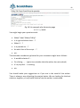
Next, it is important to fulfill all the sections of the portfolio. Below, a ready
portfolio (in editing mode) is shown.
==Name of author (s) of the project and the reference (s) of person (s) on
the page http://http://wiki.scratchduino.com/==
46
[[User:Elena Vostrikova]]
==Category party==
Party outside the category
==Nomination serving festival project==
ScratchDuinoLab
==Description of the festival project==
Once in the era before the advent of computers and the Internet, children were playing Battleship on the slot machines. Now you can play its
online version at this address http://morskoy-boy.15kop.ru/game/
We have created a semblance of the game. At the top of the screen,
there are sail boats, while at the bottom of the screen there is a gun. The
gun is moved by the left and right buttons on ScratchDuinoLab. When
you press the upper button, the gun fires and the game pauses. When
you press the lower button, the game continues. The game has several
levels. Each level increases the speed of the ships. If you miss, your life
shortens. At the background of the game the sea creatures are floating.
==Link to download the festival project==
[https://goo.gl/U5RCYx Active link to the file in "*.sb"]
[[Category: Project]]
[[Category: ScratchDuino 2016]]
Click the button Save page!
From now on, your project is available for the whole community. The comments can be read and written at the project page, at the Discussion tab.
47
Rules on Discussing the Projects at wiki.scratchduino.com
The Festival is not a contest but a live exchange of ideas, findings, and ready
projects, as well as a permanent search of the best ways to introduce the libre
robotics. That is why, along with the number and the quality of the projects uploaded, the Expert Group will consider also the number and the quality of the
discussions led by a participant.
The discussion is always a dialogue: one person puts questions and another
person answers. If somebody has left a question for you at the Discussion tab
(Fig. 65), or there are criticisms or ideas offered to make your project better, it
is considered a good practice to thank for the question and give a detailed answer, to agree with a criticism or retort against it, to consider and accept (decline) the suggestions.
Fig. 65. The Discussion tab
at the page of project portfolio.
To not reduce the discussion to just a mutual exchange of emoticons or rather
meaningless sentences like “Great!” or “Cool!”, we would suggest a “3-2-1”
strategy. It means that you have to put THREE questions, give TWO criticisms,
and offer ONE improvement. An example of a discussion following such strategy is shown in Fig. 67. On completing your message, click the Your signature
and timestamp button. You will see a character string --~~~~. Then click the
Save the page button.
You should be nice and polite with the people, especially as you are a perfect
stranger for them. When discussing a project, avoid the harsh phrases like
“Your stuff is nonsense!” in favour of something like “This idea needs certain
refinement.” It is not easy to start developing a worthy project at once, and it is
important to encourage the newbies. A friendly word can lend them wings!
48
Fig. 66. An example of a discussion page
in Editing mode.
You might begin your questions with:
When? How? Where? Why?
Is it right to believe that … ?
What if … ?
Is it possible to … ?
At which line of the script … ?
etc.
The advisable introductory phrases for your comments might be as follows:
It would be better if …
On clicking ..., … (point to a mistake that the author has not noticed)
It’s a pity that ... is missing
etc.
You should make your suggestions as if you are in the stead of the author.
There is always a way of getting the project better. We are looking for the best
solutions together, so any useful idea to help the author is welcomed.
49
Fig. 67. An example of a discussion page
in Read mode.
The Expert Group of the Festival does not deal with the anonymous messages! Having your message complete, always click the button Your
signature and timestamp.
50
Information Sources
Information environment of the project
ScratchDuino official website
File server
ScratchDuino Wiki
ScratchDuino Group at Google+
ScratchDuino video channel at YouTube
Group at VKontakte social network
http://www.scratchduino.com/
http://files.scratchduino.ru/
http://wiki.scratchduino.com/
https://goo.gl/uVRm6D
https://goo.gl/Y5jDz8
http://vk.com/scratchduino
Russian-speaking help desk
[email protected]
51
Appendix
Statutes of ScratchDuino Libre Robotics Festival
1. General Provisions
All-Russia (International, in case of foreign participants) festival “ScratchDuino
Libre Robotics” (hereinafter, the Festival) shall be held annually, in accordance
with the state policy concerning the development of educational robotics and
lifelong IT-education in the Russian Federation.
Founders of the Festival: JSC “Tyrnet” and partners.
The objectives of the Festival are:
generalization and promotion of the experience of applying the libre robotics;
introduction of libre robotics into the curriculums of primary and secondary educational institutions, as well as in the family form and for selfeducation.
Participants of the Festival: educators, students, and creative teams of adults
and children, ranked by their skills and education level.
2. The Organization of the Festival
2.1. The preparation and holding of the Festival shall be carried out by an Organizing Committee.
2.2. The Organizing Committee shall:
make a list of the Expert Group;
notify about the schedule, the procedure, and the results of the Festival;
examine the projects submitted to the Festival;
promote the best participants of the Festival.
3. The Content and the Procedure of the Festival
3.1. The Festival shall be held in 3 stages.
Stage 1— Grassroots (September–December):
the Festival participants are registering on the website
http://wiki.scratchduino.ru and uploading the portfolio of their festival projects;
52
the Festival participants study each other’s projects, make their comments, and put questions to the authors;
the participants put their applications into a self-registration sheet at a
page of the Festival website;
ScratchDuino Group at Google+ (https://goo.gl/uVRm6D) runs consultative workshops;
the information about the Festival is published by the mass media.
Stage 2— Expertise (January):
the Expert Group is working;
the best participants of the Festival are being chosen, ranked by educational level within the nominations.
Stage 3 — Final (February 7— International Day of Robotics)
the best participants of the Festival are announced and awarded.
3.2. The examination of the projects shall be made within two (or four, in case
of such kinds of projects) nominations, taking into account the educational
level:
ScratchDuino.Lab
ScratchDuino.Robokit
ScratchDuino.Lab (modification)
ScratchDuino.Robokit (modification)
3.3. The participants themselves shall upload their projects to the portal
http://wiki.scratchduino.com/ as a project portfolio, with mandatory indication of the participant category [[Category: Projects]]
[[Category: ScratchDuino 2016]]
3.4. The projects submitted shall have no feedback review of the Expert Group.
3.5. The names of the best participants of the Festival shall be placed at the
homepage of the Festival website.
4. Selection Criteria To Choose the Best Participants of the Festival
number and quality of the projects submitted;
number and quality of the discussions held by the participant on the projects of other people.
53
5. The Festival Schedule
5.1. The project portfolio is to be placed at http://wiki.scratchduino.com/
by ___ “____” 20__ .
5.2. The list of the best participants mentioning their awards is to be published
at the homepage of the Festival website on February 7 — International Day of
Robotics.
6. Awards for the Participants of the Festival
6.1. All the participants shall get the electronic certificates.
6.2. Based on the rating of their projects, the PARTICIPANTS, LAUREATES, and
WINNERS of the Festival shall be chosen, ranked by educational level within the
nominations.
User Manual
Elena A. Vostrikova, Cand.Sc. (Education),
Chief of Education Development Dept.
at Additional Vocational Training Institute, Novokuznetsk
[email protected]
Leonid S. Zakharov, programming engineer
with Kemerovo Region Department at the Russian Ministry of Interior,
Novokuznetsk
Ekaterina A. Lvova, engineering team leader of Project ScratchDuino,
St.Petersburg
[email protected]
ScratchDuino.Lab
Translation by Elena Tolstyakova
Passed for printing XX.XX.2015. 1000 copies.
JSC “Tyrnet” Reprographics Center
Medikov pr. 5/7, St.Petersburg, 197022 Russia