1
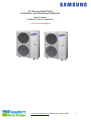
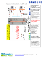
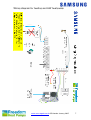
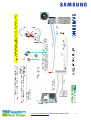
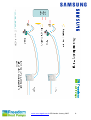
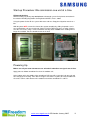
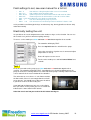
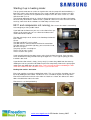
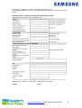
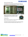
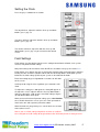
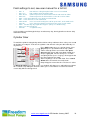
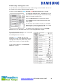
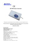
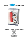
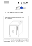
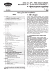
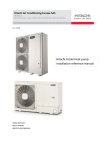
Installer
Please
Read
Instructions
Inside
www.samsungehs.co.uk ©G Hendra January 2015
1
www.samsungehs.co.uk ©G Hendra January 2015
2
Air Source Heat Pump
Installation and Maintenance Manual
Model Numbers:
RC090-120-140 and 160MHXEA
2 units connected together
www.samsungehs.co.uk ©G Hendra January 2015
3
The outdoor unit (boiler)
Deciding on Where to Install the Outdoor Units
Choose a location where the noise of the Air to Water Heat Pump when running and the
discharged air do not disturb any neighbours.
Install the outdoor unit on a flat, stable surface with plenty of drainage, gravel or grass is
ideal; make sure the base can support its weight
Position the outdoor unit so that the air flows into an open area, where there are no plants
and animals
If you can see the sea from the position of the outdoor unit you need to apply Blygold, Bronze
glow or equivalent anti-corrosion coating on the whole unit.
The unit will not benefit from being mounted on the North or south of the building, any aspect
is fine, you should avoid very exposed positions to avoid wind blowing into the back or front of
the unit.
The unit needs to be securely
mounted at least 100mm off the
ground on rubber feet. The unit
must be bolted down for security
using 10mm bolts and Zebedee
bolts. If wall brackets are used we
recommend 600mm unistrut
cantilever arms are used. Caution
should be applied when wall
mounting because any vibration
form the unit can be transmitted into
wall creating noise.
the
The unit must have adequate drainage away from the unit; it can produce up to 6 L / hour.
There is a drainage kit included which we recommend you don’t use, its best to let the unit
drain into the ground. If a drip tray is used it must be 25mm longer and wider than the base of
the unit to catch all the drips.
Dimensions:
Size 16 - 1420mm (h) 940mm (w) 330mm (d) 103kg
Size 9 - 998mm (h) 940mm (w) 330mm (d) 75kg
The space around the unit is very important, allow:
300mm to the left hand side (facing the front of the
unit), 600mm to the right of the unit, 300mm to the
rear of the unit and 1500mm to the front of the unit.
The Control Box
Each heat pump is delivered with its own control box which also contains the flow switch.
Install the control unit indoors as it’s not waterproof.
It needs to be sited less than 15m of the hot water cylinder, 100m of the outdoor unit and as
near as possible to the pump, flow switch and any zone valves.
The box is 323mm wide, 339mm high, 131mm deep
www.samsungehs.co.uk ©G Hendra January 2015
4
Pipework Schematic size 9 and 16 units
Each heat pump has 1
inch BSP male
connections; these should
be connected to flexi
hoses.
The flexi hoses have to be
insulated to conform to
MCS.
You cannot combine the
flow of the units together
without a low loss header
or buffer.
To maintain flow rate we
recommend 28mm
pipework is used with this
machine. NEVER use
22mm plastic tube, if you
insist on using plastic use
28mm throughout
You will also need to
install:
A low loss header, buffer
or 2 heat exchangers, 2
High resistance pump,
Expansion vessel,
Pressure gauge,
Pressure relief valve,
filling loop,
2 x Magnetic filter
Strainer.
2 x Flow meters
Flow switch
4 x 2 port valves
We recommend the
system has a break in it,
you can use a header, a
buffer or a heat exchanger
to do this. This is done to
maintain uninterrupted
flow.
The domestic hot water
cylinder must be
manufactured specifically
for the heat pump and
have a coil with a surface
area of 3m^2 equivalent.
www.samsungehs.co.uk ©G Hendra January 2015
5
Other components you need to supply and fit:
An expansion vessel, pressure gauge, pressure relief valve and filling
loop
Most heating engineers use a robokit with the appropriate size expansion
vessel; this is sized exactly the same way as when using a boiler.
Pump
Your pump needs to supply 20l/min for the 9kW and 30l/min for the 16kW unit.
The static resistance through the unit is 10kPa for the 9kW and 15kPa for the
16kW unit. The flow meter has a resistance of around 5kPa
The cylinders (Gledhill) have a static resistance of 5kPa for the heat pump coil
and 19kPa for the solar coil.
The total resistance of the components will be approximately 39kPa for the size
9 unit and if the cylinder is piped using both coils and approximately 44kPa for the size 16
unit.
Flow switch and flow meter
Each unit requires 17L / min flow at all times, if you don’t achieve
this E911 error will occur to check this flow switch is installed. The
flow switch comes with the control box.
The flow Switch MUST be installed in either horizontally or vertically
with at least 150mm of straight pipe either side, connection is 1” female BSP. The wire is 2m
long and needs to connect into the wiring station. This wire can be extended to suit. We
recommend a flow meter is installed into the flow side of the flow switch as per the photo.
Adaptors may be required to enable this join. The flow switch is not IP65 rated (weatherproof)
and so must not be installed externally.
Diverter valves
If you require domestic hot water and heating, diverter valves are required, you
need to supply these.
Water Filter
In all cases a filter with strainer needs to be installed in the return to the heat pump. A
magnetic filter must also be installed in the return to the unit. The filters ensure that
debris/foreign materials do not cause damage to the heat exchanger in the unit voiding
warranties.
Glycol
A propylene glycol mixture must be utilized to prevent freezing of the water within the system.
It is important that the glycol concentration is adequate to protect the unit in case of power
failure in very cold conditions. If the unit freezes up there will be no warranty. Manufacturer
dependant, a mix of around 25% should suffice.
Buffer vessels, heat exchangers and low loss headers
You don’t have to use a buffer vessel on a Samsung but we do need a minimum flow rate of
17l/min and have a circulating volume of over 20 Litre. To achieve this is much easier if you
break the system in two with a header, a buffer or a heat exchanger.
Bypass Valve
If you don’t use a header buffer or heat exchanger you must install a bypass
valve in the heating circuit as far away from the heat pump as possible. The
bypass valve enables flow to be maintained as the trv’s shut down at all times to
prevent unit flow fault.
The Cylinder:
The cylinder needs to be installed less than 15m from the control box to allow for the
temperature sensor cable. Note the size and weight of the cylinder. Full installation
instructions are included with the cylinder.
Cylinders can be used IF the coil area is more than 2.5m^2. Smaller coils are not acceptable
and cannot be used. Please do not attempt to utilize a standard central heating, non-heat
pump optimized cylinder. Cylinders can be pressurised or open vented.
www.samsungehs.co.uk ©G Hendra January 2015
6
Wiring diagram for heating and HW heat pump:
www.samsungehs.co.uk ©G Hendra January 2015
7
www.samsungehs.co.uk ©G Hendra January 2015
8
www.samsungehs.co.uk ©G Hendra January 2015
9
Wiring and Power Supply Information: Master
Power The EHS system needs 2 power supplies:
One connects into the outdoor unit, 20 Amp for the 9kW and 32 Amp for the size 16
The one for the control box is 3 Amp and wires into A1 and A2 on the PCB, the breaker must
be removed.
Communication cable
Must be run from the outdoor unit to the control box. Use 2 core flex 0.5-1mm (its 16V ac)
Sensors
The red safety sensor is to avoid over temperature, it plugs into a red socket T3 on the
controller PCB and must be fixed to the flow pipe of the heat pump before it joins the header
Thermostats/ timers and under floor heating manifolds
We recommend in all cases the heating should be controlled by an external field supplied
room stat / setback stat, time clock or a run signal from a boiler enable signal from under floor
manifolds. The heat pump run signal connects from B20 – B22, B20 is permanently live 240V
ac.
Pump
The circulation pump must be wired Live to B6 and neutral to B5, MAX pump power is 500
Watts. If two pumps are used wire them both to these terminals
Wiring and Power Supply Information: Slave
Power The Each EHS system needs 2 power supplies:
One connects into the outdoor unit, 20 Amp for the 9kW and 32 Amp for the size 16
The one for the control box is 16 Amp and wires into A1 and A2 on the PCB, the breaker must
be removed.
Immersion Heater
The immersion heater is connected into the control box terminals A3 Neutral and A4 Live, The
control box controls the operation of the immersion heater. If a fused spur is used it must be
labelled as switching it off will cause an error.
Communication cable
Must be run from the outdoor unit to the control box. Use 2 core flex 0.5-1mm (its 16V ac)
Sensors
The blue cylinder sensor plugs into a socket T4 on the
controller PCB and into the control sensor pocket in the cylinder
in the top ½ of the cylinder. Must be above immersion. The
cylinder sensor needs to go 115mm into the cylinder; it must be
clipped so it can’t pull out.
The red safety sensor is not needed.
Using two port valves
2 port valve for Hot water, wire brown wire to B9 and Blue to B7, the rest are not used.
2 port valve for heating zone 1 wire B14 live and B11 Neutral
Run signal
The run signal for this unit comes from terminal B2 in the mater unit and connects to
B22 in the slave unit.
Pump
The circulation pump must be wired Live to B6 and neutral to B5, MAX pump power is 500
Watts. If two pumps are used wire them both to these terminals
www.samsungehs.co.uk ©G Hendra January 2015
10
Start-up Procedure: We commission one unit at a time
Filling and flushing:
When installing any Heat pump we insist on a thorough system flush prior to connection in
line with the Building Regulations for England and Wales, Part L, 2006.
Using the power flusher fill the system with water and 25% Propylene Glycol to more than 1
bar.
With the power OFF, remove the front of the remote controller by sliding it upwards, turn it
over and hold the red sensor at the top. DON’T TOUCH THE PCB, there are 8 dip switches
near the red sensor, using a small screwdriver flick dip switch 1 and 5 to on. Cooling will no
longer be available. Put the controller back on the wall.
Powering Up
Makes sure all your room thermostats are off and all underfloor run signals are off first.
Apply power to indoor control box first then the outdoor unit.
At the indoor unit In the middle of the control box PCB you will see two tiny leds one red and
one orange/green flashing. If this doesn’t happen check there is power on at the outdoor unit.
Check the comms cable between the outdoor unit and the control box F1 and F2.
www.samsungehs.co.uk ©G Hendra January 2015
11
Setting the Clock
Press the grey set button for 5 seconds.
The day will flash, adjust this with the silver up and down
buttons, press grey set.
The hours will flash adjust this with the silver up and down
buttons, press grey set.
The minutes will flash, adjust this with the silver up and
down buttons, press grey set you are back to the normal
screen.
Field Settings
Field settings are what define how the unit is configured and how it will work, each system
can have very different field settings.
Many field settings will need to be made: NOTE the set button is the grey one not the blue
Field settings are in groups the 20s are for weather compensation and temperature control in
heating, the 30s are for the cylinder and the 40s are for backup boilers and hybrid systems.
Below are the field setting specific to your system as described in this book.
Enter field settings by pressing test for 6 seconds, 10 will show
on the screen
Scroll up to 20 using the silver up button, press set, 2011 will
show.
To adjust this setting press set again the setting will appear at
the top of the screen, adjust it with the silver up down buttons
and press set again, scroll up to the next field setting using the
up and down buttons and repeat.
When you have finished all your 20 settings press cancel delete
once, 20 will show on the screen, press the silver up button to
move to the 30s and repeat the procedure above.
When finished or if you get lost press cancel delete 2 x to return
to the normal screen
Note: if you set a field setting and go back to check it, it will not
have changed, the field setting do not get written to the PCB until you finish setting and exit.
www.samsungehs.co.uk ©G Hendra January 2015
12
Field settings to set, see user manual for a full list
•
•
•
•
•
•
•
2011 -2
low ambient setting for optimisation set to -5 in Scotland
2012 +15
high ambient temp for optimisation
2021 45-50
Flow temperature in cold weather 50C for rads 45C for ufloor
2022 37C
Flow temperature in mild weather 37 for rads 37C for ufloor
2091 1 tells unit to look for a run signal on terminal B22
4021 1
tells unit a backup heat pump is present
4024 +10
tells unit not to use the backup heater if ambient is above +10C
# it is possible to scroll through the days & select every day, then legionella can be run daily
rather than weekly.
Electrically testing the unit:
It is possible to test each component one after another using a service function. You can use
this to make sure you have wired everything correctly.
To access service mode press blue set button and test button together for 6 seconds.
The controller will display TEST.
Press the top left button the unit will run the pump.
To test the external run signal or stat is connected adjust
temperature on stat up.
Heat1 will replace test on screen.
To exit service mode press and hold cancel delete for 6
seconds
Test 1
Firstly in test mode run the pump, press blue set button and test button together for 6
seconds. The controller will display TEST. Immediately press the top left button to turn the
pump on and leave it running while in test mode. When the pump is running a little house with
a circle around it in the status window of the controller.
The unit wants to see at least 17 l / min flow to activate
the flow switch, if there is not enough flow the unit will
never operate. You should have a flow meter installed,
if you haven’t now is the time to buy one.
If you look into the flow meter you can see the flow in
litres per minute. In this picture you can see a flow rate
indicated, this shows 25l/min NOT 35l/min
If the flow rate is too low you need to fix this before moving on.
www.samsungehs.co.uk ©G Hendra January 2015
13
Starting it up in heating mode:
Turn up your thermostats to send a run signal to the unit, the pump will start immediately, a
little house with a circle round it appears in the status window, when the compressor starts
after 3 minutes, you will see the symbol for the compressor in the status screen. It’s a little
milk churn with a c in it.
The pipework will begin to heat up, check the flow temperature by pressing blue view button
once, the temp of the flow is shown next to a symbol of a house in a circle. Over time this will
warm up, now check all the radiators or U floor loops are hot as well.
E911 and compressor not running, E911 means the water is not moving
fast enough to push the paddle switch.
If you look into the flow meter you can see the flow in litres per
minute. In this picture you can see a flow rate indicated, this
shows 25l/min NOT 35l/min
The flow switch trips out at 15l/min, if the flow drops below this
E911 shows.
Check:
The flow rate MUST is over 17l/min
The flow switch is connected to the PCB of the control box
The flow switch is round the right way, you can turn the head,
All valves are open.
The pump speed is set at highest
There is no air in the system
There is water in the system
If you manually open the hot water 2 way valve check the flow rate again, if you can only
reach 16l with the heating and hot water open together it’s a sure sign the pump you have
installed is too small.
If you think the flow switch is faulty, (it very rarely is) remove the paddle from the water by
undoing the red nut, you will need to block up the hole temporarily. Now run the pump again
switch your stats down then up again. After 3 mins of pump operation and holding the flow
switch the outdoor unit will start, don’t rush the system it takes time
Rattling flow switch / Cavitation
E911 fault could be caused by a rattling flow switch. This can usually be heard but can also
be felt by holding the flow switch. To correct it use a screwdriver or pliers on the top of the
Flow meter and turn the ball-o-fix valve from 12 o’clock to 1 o’clock; this deflects the water
flow & should further reduce the rattle.
Flow meter in 1 o’clock positioning:
www.samsungehs.co.uk ©G Hendra January 2015
14
Please return a photo or scan of this form and the delivery note to
[email protected] Once received we will confirm receipt and start of the warranty
period.
I accept the terms of the Samsung warranty and confirm the system has been registered
within 30 days of delivery. I also include a copy of the delivery note.
Signed
Name
www.samsungehs.co.uk ©G Hendra January 2015
15
Start-up Procedure: Slave
With the power OFF, remove the front of the remote controller by sliding it upwards, turn it
over and hold the red sensor at the top. DON’T TOUCH THE PCB, there are 8 dip switches
near the red sensor, using a small screwdriver flick dip switch 1 and 5 to on. Cooling will no
longer be available. Put the controller back on the wall.
Setting up the cylinder immersion heater
The immersion heater has its own stat; this MUST be set to 70C. This
is to avoid the immersion heater cutting out before the legionella
function is complete
Powering Up
Makes sure all your room thermostats are off and all underfloor run signals are off first.
Apply power to indoor control box first then the outdoor unit.
At the indoor unit In the middle of the control box PCB you will see two tiny leds one red and
one orange/green flashing. If this doesn’t happen check there is power on at the outdoor unit.
Check the comms cable between the outdoor unit and the control box F1 and F2.
www.samsungehs.co.uk ©G Hendra January 2015
16
Setting the Clock
Press the grey set button for 5 seconds.
The day will flash, adjust this with the silver up and down
buttons, press grey set.
The hours will flash adjust this with the silver up and down
buttons, press grey set.
The minutes will flash, adjust this with the silver up and
down buttons, press grey set you are back to the normal
screen.
Field Settings
Field settings are what define how the unit is configured and how it will work, each system
can have very different field settings.
Many field settings will need to be made: NOTE the set button is the grey one not the blue
Field settings are in groups the 20s are for weather compensation and temperature control in
heating, the 30s are for the cylinder and the 40s are for backup boilers and hybrid systems.
Below are the field setting specific to your system as described in this book.
Enter field settings by pressing test for 6 seconds, 10 will show
on the screen
Scroll up to 20 using the silver up button, press set, 2011 will
show.
To adjust this setting press set again the setting will appear at
the top of the screen, adjust it with the silver up down buttons
and press set again, scroll up to the next field setting using the
up and down buttons and repeat.
When you have finished all your 20 settings press cancel delete
once, 20 will show on the screen, press the silver up button to
move to the 30s and repeat the procedure above.
When finished or if you get lost press cancel delete 2 x to return
to the normal screen
Note: if you set a field setting and go back to check it, it will not
have changed, the field setting do not get written to the PCB until you finish setting and exit.
www.samsungehs.co.uk ©G Hendra January 2015
17
Field settings to set, see user manual for a full list
•
•
•
•
•
•
•
•
•
•
•
2011 -2
low ambient setting for optimisation set to -5 in Scotland
2012 +15
high ambient temp for optimisation
2021 45-50
Flow temperature in cold weather 50C for rads 45C for ufloor
2022 37C
Flow temperature in mild weather 37 for rads 37C for ufloor
2091 1 tells unit to look for a run signal on terminal B22
3011 1 tells unit it has a tank connected
3025 50-90
mins, max tank heating time, 50 for up to 210L, 75 for 300L tanks
3032 30
mins, delay time before immersion heater starts in tank mode
3042 Wednesday day legionella happens (always use Wednesday)
3043 3 am time it happens
3044 60
C legionella temp
# it is possible to scroll through the days & select every day, then legionella can be run daily
rather than weekly.
Cylinder timer
To avoid the cylinder heating being switched off we always add 2 on timers a day, one at 3-00
am and one at 15-00 pm. To insure the cylinder is hot 24 hours a day we don’t normally set
any off times.
Press daily button once, no 1 and on shows, press
grey set, press up or down until the tap symbol
shows at the top of the screen with 2 dots press
grey set, adjust hours with up or down button to 3
am press grey set, minutes flash press set. Now
everything flashes press set (grey). No 2 appears do
the same again but for 15-00.
After everything is set no 3 will show. Press cancel
delete twice, the normal screen will show.
Daily will appear next to the time. The timer is active.
To delete the timers press daily 2 x the set schedule will show, press and hold cancel delete
for 5 seconds, keep doing this until no1 shows, press cancel delete 2 x and in the normal
screen daily will have disappeared.
www.samsungehs.co.uk ©G Hendra January 2015
18
Electrically testing the unit:
It is possible to test each component one after another using a service function. You can use
this to make sure you have wired everything correctly.
To access service mode press blue set button and test button together for 6 seconds.
The controller will display TEST. Immediately press the
top left button to turn the pump on and leave it running
while in test mode to avoid a fault.
Press the top left button the unit will run the pump.
Press weekly to test the immersion heater in the hot
water cylinder.
The hot water valve should be closed, Press the lock
button to make a coke can appear the HW valve should
move to open, press lock again to close it.
The Heating valve will be open, Press the top right
button to close it. 2-1 will show on the screen, Press top right to open it again.
To test the external run signal or stat is connected
adjust temperature on stat up.
Heat1 will replace test on screen.
Using the blue view button you can see 5
temperature sensors, inlet and outlet to the heat
exchanger, the red sensor (where used), water
cylinder and sensor in the remote controller.
To exit service mode press and hold cancel
delete for 6 seconds
www.samsungehs.co.uk ©G Hendra January 2015
19
Test 1 To Avoid further problems we recommend you set
the units up in test mode before starting the heat pump.
Firstly in test mode run the pump, press blue set button and test button together for 6
seconds. The controller will display TEST. Immediately press the top left button to turn the
pump on and leave it running while in test mode. When the pump is running a little house with
a circle around it in the status window of the controller.
The unit wants to see at least 17 l / min flow to activate
the flow switch, if there is not enough flow the unit will
never operate. You should have a flow meter installed,
if you haven’t now is the time to buy one.
If you look into the flow meter you can see the flow in
litres per minute. In this picture you can see a flow rate
indicated, this shows 25l/min NOT 35l/min
If the flow rate is too low you need to fix this before moving on.
Starting it up in heating mode:
Turn up your thermostats to send a run signal to the unit, the pump will start immediately, a
little house with a circle round it appears in the status window, when the compressor starts
after 3 minutes, you will see the symbol for the compressor in the status screen. It’s a little
milk churn with a c in it.
The pipework will begin to heat up, check the flow temperature by pressing blue view button
once, the temp of the flow is shown next to a symbol of a house in a circle. Over time this will
warm up, now check all the radiators or U floor loops are hot as well.
Starting the System in hot water mode
Press Hot water on off button to start the unit, top right
button.
Set the desired temperature to 48C press blue set
button once until a tap shows now set using the up and
down buttons.
The unit will take up to 6 minutes to start in Hot water
mode, be patient don’t press buttons. When the unit is
heating the cylinder this coke can symbol shows on
the controller.
Run test in hot water mode
In hot water mode check that the 2 ports are sending water into the hot water cylinder, Using
the view button (blue) on the remote controller check the hot water cylinder temperature and
note it down, the hot water temperature is displayed when the tap symbol shows.
After 15 minutes of running check the hot water temperature again, it should have risen, again
note the temperature. If the temperature has not risen check the blue temperature sensors is
installed properly. If the unit is running well it should heat the cylinder to 48C without needing
the immersion heater
Not enough hot water.
The Water storage temperature is lower (48C) than a normal fossil fuel cylinder. It’s important
to check that any shower or bath mixers do not further reduce the water temperature. Using
your thermometer check that the hot water comes out the tap at the same temperature it
leaves the cylinder. If it doesn’t you might need to make adjustments to taps mixers etc.
DON’T raise the cylinder temperature to compensate.
www.samsungehs.co.uk ©G Hendra January 2015
20
Problems:
If there is a problem see page 14
Caution in Cold weather
If the water in the system is below 10C the heat pump WILL NOT START.
Press the blue view button, you can see 4 sensor readings, press it until the pump symbol
shows (a circle round a house). This is the water temperature, if it’s below 10C the unit will
not start but the pump will run.
You must warm up the water to get the unit to run, the easiest way to do this is to run the
immersion in Test mode (page 13) to warm up the cylinder first, by manually cranking open
the HW valve you can prime the heat pump with the warm water coming back from the
cylinder.
If everything is cold less than 5C (the remote controller, the water, the tank etc.) the unit will
not operate correctly, it can’t understand how the house has got so cold. You will find the on
off button for heating won’t work and if you try to use HW mode it will switch itself off. You
need to allow the unit to warm up first. Make sure the remote controller is in a heated room.
www.samsungehs.co.uk ©G Hendra January 2015
21
Warranty Registration Card
Warranty MUST be registered within 30 days of delivery to
site. You must send proof of delivery with the warranty card.
Warranty will start from the date the unit is delivered.
All registrations made more than 30 days after this period will be rejected.
If commissioning data is not available at this time register the unit and send the data at a later
date, the warranty certificate will be returned to you when the whole form is completed.
This warranty covers only the Samsung components of the installation, it is parts with a preset labour allowance only. The warranty is between Freedom Heat pumps and the installation
company only, this is NOT an end user warranty.
It is the role of the installer to offer a warranty to the end user covering all of the heating
system including the heat pump.
The standard warranty is valid for 12 months from date of delivery as entered on this card. If
the unit is installed by a Samsung approved installer and this card is sent back within 30 days
of delivery date the warranty is automatically extended to 36 months.
Approved installers also have access to warranty extensions at the time of registration for
warranty; a 4 year extension to the warranty can be purchased from your distributor or directly
from Freedom Heat Pumps.
Call 02380274833 for details and pricing
The warranty card can also be used as a maintenance card.
www.samsungehs.co.uk ©G Hendra January 2015
22
Please return a photo or scan of this form and the delivery note to
[email protected] Once received we will confirm receipt and start of the warranty
period.
I accept the terms of the Samsung warranty and confirm the system has been registered
within 30 days of delivery. I also include a copy of the delivery note.
Signed
Name
www.samsungehs.co.uk ©G Hendra January 2015
23
Maintenance Monobloc Systems
The Samsung heat pump should be maintained at least once a year to comply with warranty
and RHI. The warranty card also doubles up as a maintenance sheet.
Maintenance procedure
Stop the unit, clean the strainer or magnetic filter in accordance with manufacturer’s
recommendations and replace it.
Test the concentration of the Anti-freeze (glycol) in the system using a Glycol tester the level
should be 25%. If you don’t have a glycol tester a glycol tester / refractometer can be bought
from your heat pump supplier or online.
Refill the unit, pressure should be 1 -2 bar,
We need to test the operation of the unit against the hot water cylinder. So first we need to
draw off 50 liters of water, run a couple of taps for 5 mins to achieve this. The unit should start
up automatically in hot water mode, if it doesn’t press the top right button on the controller, in
3-4 mins it will start heating the cylinder, a coke can symbol will show in the status section of
the remote controller.
The heat pump should be able to achieve 48C cylinder temperature without using the
immersion heater.
While running, check the outdoor unit for damage & debris, the coil needs washing, we
recommend you use an approved EHS heat pump cleaning chemical, your distributor will
stock this. Instructions are given on the bottle. You also need to clean and polish the outside
casing we recommend car wax to do this.
Hot water Cylinder:
Check electrical connections & sensor are fixed properly and the
overheat thermostat is set to 70C.
Overheat Thermostat
Adjustment
Press the silver immersion button on the Samsung remote controller; this will force the
immersion heater on. Check immersion heater works properly, Measure the current drawn by
the heater; it should be 12-13 Amps.
Measure the temperature of the flow using the remote controller.
Measure the flow rate from the flow meter.
With the unit running flat out measure the temperature of the air as it enters the coil and the
temperature of the air in the garden. They should be the same check cold air is not
recirculating.
www.samsungehs.co.uk ©G Hendra January 2015
24
Explaining the Operation of the Master System to the end
user
You have now set the unit up to run from an external signal Using a field supplied room
thermostat or signal from an under floor heating system through B20-B22 and/or B20-B24;
the controller no longer drives the unit.
When the contact is made the unit will start and the water temperature will be controlled by
the heat pump, you will not have any control over it. The water temperature is determined by
the outdoor temperature; the colder it is outside the warmer the water. The unit is running in
weather comp mode,
You will see 0.0C on the
screen; the unit is using
weather compensation
function to work out the water
temperature. If you need to
boost the heating water temp
this can be done by pressing
the silver up and down
buttons. This boosts the
radiators by up to +5 C but
warning this will cost more
money to run.
When an external stat or run
signal is used most of the
functions of the Samsung remote are disabled. A waging finger shows at the bottom to show
this.
All these buttons are disabled and the functions they control are also disabled
Note:
when the heating command is
sent to the unit it will not start for 3
minutes. And when the thermostat or
signal is removed the pump will run on for
up to 6 minutes.
On latest software the end user can
override the stat switching the unit off with
the top left button. Avoid this as the unit
will no longer run. If the sun signal is not
on the display the heating is not going to
operate.
How the slave works:
When the master unit is struggling to heat the house and the ambient temperature is below
10C the slave unit will be asked to help out.
How hot water works
The hot water cylinder has priority over the heating, if the cylinder temperature falls 5 degrees
below its set point the unit will automatically switch to heating the cylinder. Once set
temperature is achieved the unit will go back to heating the house.
The hot water cylinder loses almost no heat (1/3 a degree an hour) if no hot water is used.
The hot water cylinder takes less than an hour to heat up from cold. If you need hot water
very fast the DHW button forces the unit to heat the water flat out, the unit will stay in this
mode until you press the DHW button again
To protect from legionella the cylinder is heated to 60 degrees C once a week automatically.
www.samsungehs.co.uk ©G Hendra January 2015
25
Leave this page with the Homeowner
Your Samsung heat pump heats the house and hot water cylinder much like a normal
fossil fuel boiler however there are a couple of differences which you should notice.
1
The radiator temperatures are lower than normal and will alter as the outdoor
temperature changes. The colder it is outside the warmer the rads and vice versa.
This function is automatic and is designed to save you money. At their hottest they
will reach 50C. If you would like a constant radiator temperature this can be set by an
engineer but it will increase your run costs by up to 25%.
2
The system is designed to run continuously in cold weather, turning the system on
and off will make the house uncomfortable and will increase your run costs. The most
efficient way to run this heating system is to leave it running at the set temperature 24
hours a day in winter time. If you turn off the heating and let the house get cold (less
than 17C) it will take a very long time to warm back up to a sensible temperature.
Your systems have been set up to be simple to operate.
The Samsung controller looks like this, you should not use this or
press the buttons on it, it is for commissioning and making settings
to the system only.
You should see 0.0C on the screen this means the unit is under
external control from a room thermostat.
If the system goes into fault, the screen will show a number at the
bottom starting with E, for example E911 – A00
The engineer will want to know this number when you call him.
Heating
Control of the heating is by your wall mounted thermostat, not the Samsung controller; you
need to read the instructions for this thermostat as its field supplied. The boiler will run when
told to by the thermostat. DON’T set the room temperature too low, the heat pump takes time
to recover the house temperature, as a rule don’t set the temperature more than 2 degrees
below your normal set temperature when you go out of the house or it will take a long time to
recover.
To switch off the heating in summer set the temperature down to 16C to avoid the heating
starting up.
To control the temperature in your rooms please use the radiator valves.
Hot water
Your system will keep the hot water cylinder hot at all times automatically, as you use the
water the heat pump will constantly top up the cylinder. A cold cylinder should be reheated
within an hour. An anti-legionella operation will be completed at a predetermined time every
Tuesday morning. The hot water will be hotter on a Tuesday morning than the rest of the
week.
Warranty Important
Attached to this document is a warranty page your installer must fill it in and return it to
activate the warranty. No claim will be processed without this paperwork being returned. Your
installer will offer you some warranty packages to cover your installation and their own work.
www.samsungehs.co.uk ©G Hendra January 2015
26