1
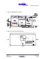
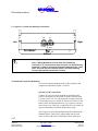
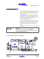
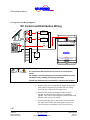
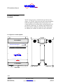
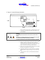
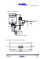
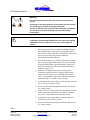
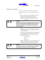
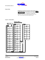
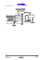
INCORPORATED RE Installation Manual F 3 Figure 3-3: Inverter AC Raceway Connections 26 27 Left Right L1 N GND L2 AC OUT L1 N GND L2 AC IN 29 28 Bottom Warning Class 1 Wiring Methods Are To Be Used For Field Wiring Connections To Terminals Of A Class 2 Circuit. It Is Also Extremely Important To Observe A Physical Separation Between Class 1 And Class 2 Circuits. Be Sure To Route Class 1 And Class 2 Wiring Through Separate Knockouts And Conduits. Terminal and Component Definitions This section contains the descriptions of the connectors and components called out in Figure 3-2 and 3-3. (22) and (23) DC connections Connect 24 or 48 volt DC (depending on your RE model) positive and negative to the inverter’s flat DC terminals with 5/16 cap screws. Use 5/16 ring terminals or compression lugs. For the RE24-4500 use a #02286-08, JJN-400, 400A fast blow fuse and 4/0 cable, and for the RE48-4500, use a #02286-03, JJN-200, 200A fast blow fuse. This fuse is required by UL to be within 18 inches of the Battery Terminals on the battery string. The wiring of your inverter installation should conform to the National Electric Code (NEC) and any other state or local codes in effect at the time of installation. These codes have 3-12 Copyright 2001 Vanner Inc. 4282 Reynolds Dr. Hilliard Ohio 43026 Phone: (614) 771-2718 FAX: 614-771-4904 www.vanner.com RE-Installation_Manual_Rev01e RE-4500 Owners Manual Rev 01e 910157-A