1
P-965
A/V Tuner Pre Amplifier
Introduction
ENGLISH
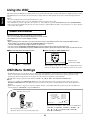
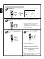
READ THIS BEFORE OPERATING YOUR UNIT
This symbol is intended to alert the user to the
presence of uninsulated "dangerous voltage"
within the product's enclosure that may be of
sufficient magnitude to constitute a risk of
electric shock to persons.
CAUTION
WARNING
: TO REDUCE THE RISK OF
ELECTRIC SHOCK, DO NOT
REMOVE COVER (OR BACK). NO
USER-SERVICEABLE PARTS
INSIDE. REFER SERVICING TO
QUALIFIED SERVICE PERSONNEL.
This symbol is intended to alert the user to the
presence of important operating and
maintenance (servicing) instructions in the
literature accompanying the appliance.
: TO REDUCE THE RISK OF FIRE OR ELECTRIC SHOCK,
DO NOT EXPOSE THIS APPLIANCE TO RAIN OR MOISTURE.
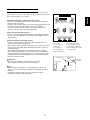
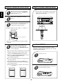
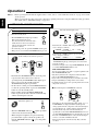
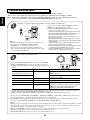
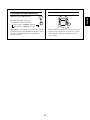
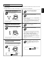
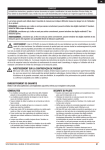
Caution regarding placement
To maintain proper ventilation, be sure to leave a space around the unit (from the largest outer
dimensions including projections)
equal to, or greater than, shown below.
Left and right panels : 10 cm
Rear panel : 10 cm
Top panel : 30 cm
Do not block ventilation openings or stack other equipment on the top.
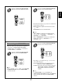
FOR YOUR SAFETY
EUROPE
AUSTRALIA
220 V
240 V
Units shipped to Australia are designed for operation on 240 V AC only.
To ensure safe operation, the three-pin plug supplied must be inserted only into a
standard three-pin power point which is effectively earthed through the normal household
wiring. Extension cords used with the equipment must be three-core and be correctly
wired to provide connection to earth.
Improper extension cords are a major cause of fatalities. The fact that the equipment
operates satisfactorily does not imply that the power point is earthed and that the
installation is completely safe. For your safety, if in any doubt about the effective earthing
of the power point, consult a qualified electrician.
PAN-EUROPEAN UNIFIED VOLTAGE
All units are suitable for use on supplies 220~240 V AC.
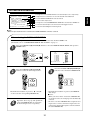
•
•
•
•
•
•
•
•
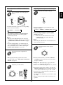
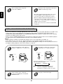
Avoid high temperatures. Allow for sufficient heat dispersion when installed on a rack.
Keep the set free from moisture, water, and dust.
Do not let foreign objects in the set.
Handle the power cord carefully. Hold the plug when unplugging the cord.
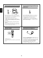
Unplug the power cord when not using the set for long periods of time.
Do not obstruct the ventilation holes.
Do not let insecticides, benzene, and thinner come in contact with the set.
Never disassemble or modify the set in any way.
CAUTION
• The ventilation should not be impeded by covering the ventilation openings with items, such
as newspapers, table-cloths, curtains, etc.
• No naked flame sources, such as lighted candles, should be placed on the apparatus.
• Please be care the environmental aspects of battery disposal.
• The apparatus shall not be exposed to dripping or splashing for use.
• No objects filled with liquids, such as vases, shall be placed on the apparatus.
2
CONTENTS
READ THIS BEFORE OPERATING YOUR UNIT
• System Connections
| 4
• Front Panel Controls
| 13
ENGLISH
• Introduction
| 2
• Universal Remote Controls
| 15
OPERATING COMPONENTS WITH REMOTE CONTROL
REMOTE CONTROL OPERATION RANGE | 18
LOADING BATTERIES | 18
ENTERING A SETUP CODE | 19
| 18
• ROOM 2 Remote Controls
REMOTE CONTROL OPERATION RANGE
LADING BATTERIES | 21
| 21
• Operations
LISTENING TO A PROGRAM SOURCE | 22
SURROUND SOUND | 25
ENJOYING SURROUND SOUND | 28
LISTENING TO RADIO BROADCASTS | 33
LISTENING TO RDS BROADCASTS(FM only)
| 36
(RDS Tuner(Regional Option for some countries in Europe, etc.)
RECORDING | 39
DIGITAL AUDIO RECORDING WITH MD RECORDER | 40
OTHER FUNCTIONS | 41
ROOM 2 SOURCE PLAYBACK | 43
• Using the OSD
CURRENT STATUS DISPLAY
| 44
• OSD Menu Settings
| 44
SETTING THE SPEAKER SETUP | 46
SETTING THE SYSTEM SETUP | 51
SETTING THE SURROUND SETUP | 57
SETTING THE CH LEVEL SETUP | 60
SETTING THE ROOM2 FEED SETUP | 63
• Troubleshooting Guide
• Specifications
| 65
| 66
3
ENGLISH
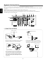
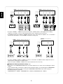
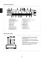
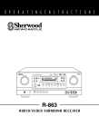
System Connections
• Pleas be certain that this unit is unplugged from the AC outlet before making any connections.
• Since different components often have different terminal names, carefully read the operating instructions of the component
connected.
• Be sure to observe the color coding when connecting audio and video cords.
• Make connections firmly and correctly. If not, it can cause loss of sound, noise or damage to the unit.
• If the electricity fails or the AC input cord is left unplugged for about 2 weeks, the memorized contents will be lost.
Should this happen, memorize them again.
3
10 7
IN3
Y
4,10
CB
IN2
CR
Y
CB
COMPONENT
1
8
12
9
IN1
CR
Y
CB
CR
Y
MONITOR OUT
IN1
IN2
OUT
IR
AC INLET
230V~50Hz
50W
OPR.
SVC.
USB
SW2
PREOUT
DIGI-LINK
1
2
DC TRIGGER OUT
12V d.c. 100mmA
AM
LOOP
FM
75
RS-232C
CB
CR
MONITOR OUT
OPT IN4
CENTER
SW1
AUX
OUT
VIDEO1
OUT
TAPE
OUT
VIDEO2/
ROOM2
OUT
OPT IN3
FRONT
OPT IN2
6
SURR.
MANUFACTURED UNDER LICENSE FROM DOLBY
LABORATORIES. "DOLBY", "PRO LOGIC", AND THE
DOUBLE-D SYMBOL ARE TRADEMARKS OF DOLBY
LABORATORIES.
MANUFACTURED UNDER LICENSE FROM DIGITAL
THEATER SYSTEMS, INC. U.S. PAT. NO'S. 5,451,942;
5,956,674; 5,974,380; 5,978,762; 6,487,535 AND OTHE
U.S. AND WORLD-WIDE PATENTS ISSUED AND
PENDING. "DTS", "DTS-ES", "DTS 96/24" AND "NEO:6"
ARE TRADEMARKS OF DIGITAL THEATER SYSTEMS,
INC. COPYRIGHT 1996, 2003 DIGITAL THEATER
SYSTEMS, INC. ALL RIGHTS RESERVED.
AUX
VIDEO 1
TAPE
VIDEO 2
CD
VIDEO3
OPT IN1
SURR.
BACK
MODEL NO. P-965
A/V TUNER PREAMPLIFIER
AC OUTLET
SW
CENTER
OUT
DESIGNED IN USA
ASSEMBLED IN KOREA
GND
FRONT
SER. NO
VIDEO 4
SURR.
VIDEO 5
PHONO
COAX IN1
R
L
R
L
SURR.
BACK
R
8CH DIRECT IN
L
8CH DIRECT IN
COAX IN2
COMPOSITE
DIGITAL
5
4
3
2
S-VIDEO
5
SWITCHED
230V~50Hz
TOTAL 100W MAX
11
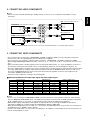
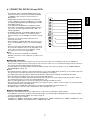
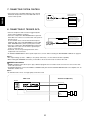
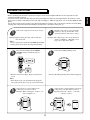
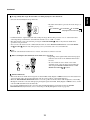
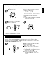
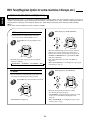
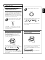
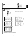
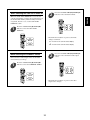
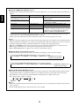
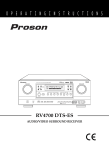
1. CONNECTING ANTENNAS
FM Indoor Antenna
FM Outdoor Antenna
• A 75Ω outdoor FM antenna may be used to further improve the reception. Disconnect the indoor
antenna before replacing it with the outdoor one.
• Change the position of the FM indoor antenna until you
get the best reception of your favorite FM stations.
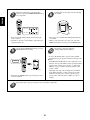
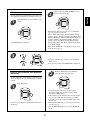
AM Outdoor Antenna
AM Loop Antenna
AM Loop Antenna
• Place the AM loop antenna as far as possible from
the receiver, TV set, speaker cords and the AC input
cord and set it to a direction for the best reception.
• If the reception is poor with the AM loop antenna, an
AM outdoor antenna can be used in place of the AM
loop antenna.
4
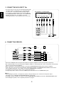
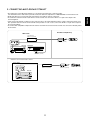
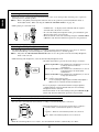
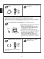
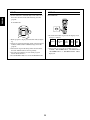
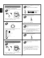
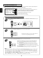
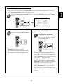
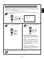
2. CONNECTING AUDIO COMPONENTS
AUX CD recorder, MD recorder, etc.
TAPE MONITOR Tape deck, MD recorder, etc.
L AUDIO
R IN
L AUDIO
R OUT
AUX
OUT
AUDIO L
IN
R
AUDIO L
OUT R
TAPE
OUT
AUX
CD CD player, etc.
TAPE
PHONO Turntable with MM type cartridge
L AUDIO
R OUT
CD
GND
GND
AUDIO L
OUT R
PHONO
R
L
• The TAPE MONITOR IN/OUT jacks may also be connected to the LINE OUT/IN jacks of an optional graphic equalizer.
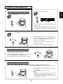
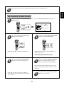
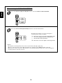
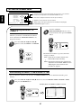
3. CONNECTING VIDEO COMPONENTS
• There are three types of video jacks ( COMPONENT, S-VIDEO, (composite) VIDEO ) for connecting video components.
Connect them to the corresponding video jacks according to their capability.
• For your reference, the excellence in picture quality is as follows : “COMPONENT” >“S-VIDEO”>(composite) “VIDEO” .
• When making COMPONENT VIDEO connections, connect “Y” to “Y” , “CB” to “CB” (or “B-Y” , “PB”) and “CR” to “CR” (or “R-Y” ,
“PR” ).
• When connecting to video recording component such as video deck, DVD recorder, etc . or TV for ROOM 2, you must use
the same type of video jacks that you did connect to video playback components such as DVD player, LD player, etc.
• This unit is equipped with a function that up-converts composite video or S-Video signals to component video signals or downconverts S-Video signals to composite video signals and outputs them from the MONITOR OUTs. Because of this, one of
three types of MONITOR OUT jacks can be connected to the monitor TV regardless of how the video components are
connected to VIDEO IN jacks of this unit.
• Connect the video components, referring to the following table.
Relationship between the video input signal and video output signal
MONITOR OUTs
Video input signals
COMPONENT
S-VIDEO
×
×
×
(composite) VIDEO
×
×
×
×
×
×
VIDEO 2 / ROOM 2 OUTs
COMPONENT
S-VIDEO
(composite)VIDEO
S-VIDEO
(composite) VIDEO
Composite
Composite
Composite
×
Composite
S-Video
S-Video
S-Video
S-Video
×
S-Video
S-Video
Composite
S-Video
Composite
Component
×
×
×
×
Component
Composite
Composite
×
Composite
Component
S-Video
S-Video
S-Video
×
Component
S-Video
Composite
S-Video
Composite
Notes :
• In such a case of making only COMPONENT VIDEO connections between this unit and video component, while viewing a
movie via MONITOR COMPONENT OUTs, if the OSD menu operation is performed with the OSD, CURSOR control(▲, ▼,
◀, ▶), ENTER buttons, etc., the picture is automatically turned off and only the OSD menu is displayed.
• When S-Video signals and composite video signals are input into this unit, even though the OSD menu operation is
performed, the OSD menu cannot be displayed via MONITOR (composite) VIDEO OUT.
• When Sherwood DVD player such as V-756 , etc. is connected to the DIGI-LINK jack for system control, you should connect
the DVD player to the “ VIDEO 2” jacks of this unit.
Because, if the PLAY button, etc. is pressed on the DVD player, the VIDEO 2 is automatically selected as an input source on
this unit. Then playback, etc. starts.
5
ENGLISH
Note:
• Do not connect the turntable with MC type cartridge directly. If you have it, use a separate head amplifier or set-up
transformer.
VIDEO 2 DVD player, DVD recorder, etc.
VIDEO 1 Video deck, DVD recorder, etc.
Y
ENGLISH
CB
Y
COMPONENT
OUT
CR
CB
AUDIO
OUT
R L
AUDIO
IN
R L
(COMPOSITE)
VIDEO
OUT IN
COMPONENT
OUT
CR
S-VIDEO
OUT IN
AUDIO
OUT
R L
(COMPOSITE)
VIDEO
OUT
IN
S-VIDEO
OUT IN
IN2
IN1
VIDEO2/
ROOM2
OUT
VIDEO1
OUT
Y
AUDIO
IN
R L
CB
Y
CR
CB
COMPONENT
CR
VIDEO2/
ROOM2
OUT
VIDEO 1
VIDEO 1
VIDEO 2
• The jacks of VIDEO 1 / VIDEO 2 may also be connected to a DVD recorder or other digital video recording
component. For details , refer to the operating instructions of the component to be connected.
• For ROOM 2 playback, the VIDEO 2 / ROOM 2 OUT jacks can be connected to the amplifier, TV , etc. installed in
another room. (For details , refer to “ROOM 2 connections” on page 10.)
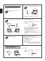
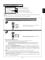
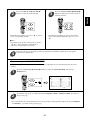
MONITOR TV, Projector, etc.
VIDEO 3 DVD player, LD player, Video deck, etc.
Y
CB
CR
Y
COMPONENT
OUT
CB
AUDIO
OUT
R L
(COMPOSITE)
VIDEO
OUT
CR
S-VIDEO
OUT
VIDEO3
CB
(COMPOSITE)
VIDEO
IN
S-VIDEO
IN
MONITOR OUT
IN3
Y
COMPONENT
IN
Y
CR
CB
CR
MONITOR OUT
• The jacks of VIDEO 3 / VIDEO 4 / VIDEO 5 can also be connected to an additional video component such as a
cable TV tuner, an LD player or satellite system .
• Connect the jacks of VIDEO 4 / VIDEO 5 to the video components in the same way.
Component video input default settings : (*)
• If you connect the COMPONENT VIDEO INs to your video components, it is easier to do so following the default
settings.
• If your component video connections are different from the default setting , you should assign the COMPONENT
VIDEO INs you used with the “When selecting the COMPONENT VIDEO SETUP” procedure on page 54.
• The default settings are as follows :
COMPONENT IN 1 : VIDEO 1, COMPONENT IN 2 : VIDEO 2, COMPONENT IN 3 : VIDEO 3
6
• The OPTICAL and the COAXIAL DIGITAL OUTs of the
components that are connected to CD, AUX and VIDEO
1~ VIDEO 6 of this unit can be connected to these
DIGITAL INs.
• A digital input should be connected to the components
such as a CD player, LD player, DVD player, etc. capable
of outputting DTS Digital Surround, Dolby Digital or PCM
format digital signals, etc.
• If the component with OPTICAL or COAXIAL IN jack is
connected to the OPTICAL or COAXIAL OUT jack of this
unit, you can record the high quality sound of CDs , etc.
without degradation.
• For ROOM 2 playback, the COAXIAL DIGITAL OUT can
be connected to the amplifier, etc. installed in another
room.(For details, refer to “ROOM 2 connections” on page
10.)
• For details, refer to the operating instructions of the
component connected.
• When making the COAXIAL DIGITAL connection, be sure
to use a 75 Ω COAXIAL cord, not a conventional AUDIO
cord.
• All of the commercially available optical fiber cords cannot
be used for the equipment. If there is an optical fiber cord
which cannot be connected to your equipment, consult
your dealer or nearest service organization.
Note :
• Be sure to make either a OPTICAL or a COAXIAL
DIGITAL connection on each component. (You don’t need
to do both.)
USB
PC with USB port
OPT IN4
Component with
OPTICAL DIGITAL OUT
OPT IN3
Component with
OPTICAL DIGITAL OUT
OPT IN2
Component with
OPTICAL DIGITAL OUT
OPT IN1
Component with
OPTICAL DIGITAL OUT
Component such as an
MD recorder, CD recorder
with OPTICAL DIGITAL IN
OUT
Component such as an
MD recorder, CD recorder
with COAXIAL DIGITAL IN
COAX IN1
Component with
COAXIAL DIGITAL OUT
COAX IN2
DIGITAL
Component with
COAXIAL DIGITAL OUT
USB audio connection
• The USB audio connection feature allows you connect a PC to this unit to hear soundtracks from your PC. USB device
controls on the computer(such as volume) may or may not work. In either case, we recommend leaving all volume controls on
the computer max and controlling volume from this unit.
• You may update the operating software through this USB connection in the future.(For details, refer to “CONNECTING PC
FOR UPGRADES” on page 12.)
Notes:
• This USB terminal only supports 2 channel PCM signals. In case of other digital signals, loud noise or no sound may be heard
from the speakers, and it may be harmful to your ears and damages the speakers.
• The digital signals being input into this USB terminal will not be output from the OPTICAL and COAXIAL OUT jacks.
• Some operating systems(OSs) may or may not work with this USB terminal.
• The sound may be interrupted, degraded or played back incorrectly due to your PC settings and PC specifications. Refer to
the operating instructions of your PC concerning USB devices, etc.
• Don’t use other applifications on your PC when playing back through this USB connection.
• Sherwood cannot be held responsible for damage to your computer system, software crashes or failures or any other possible
computer problems due to this configuration.
• Do not disconnect the USB cable while playing a soundtrack or updating the operating software, etc.
Should this happen, it may be result in malfunction or cause damage to the unit.
Digital input default settings
• If you connect the DIGITAL INs to your components, it is easier to do so following the default settings.
• If your DIGITAL connections are different from default settings, you should assign the DIGITAL INs you used with the “When
selecting the DIGITAL INPUT SETUP” procedure on page 51.
• The default settings are as follows :
OPTICAL IN 1 : VIDEO 1, OPTICAL IN 2 : VIDEO 2, OPTICAL IN 3 : VIDEO 3, OPTICAL IN 4 : VIDEO 5, COAXIAL IN 1 : CD,
COAXIAL IN 2 : VIDEO 4, (Front) OPTICAL IN 5 : VIDEO 6, USB : AUX
7
ENGLISH
4. CONNECTING DIGITAL INs and OUTs
ENGLISH
5. CONNECTING 8CH DIRECT INs
• Use these jacks to connect the corresponding analog audio
and video outputs of a DVD player or a external decoder ,
etc. that has 6 , 7 or 8 channel audio and video outputs.
• In case of 6 or 7 channel outputs , do not connect both of
the SURROUND BACK L and R inputs or the SURROUND
BACK R input to this unit . (For details, refer to the
operating instructions of the component to be connected. )
Decoder with 6, 7 or 8 channel outputs
S-VIDEO
OUT
8 CH DIRECT OUTs
CENTER
SUBWOOFER
FRONT
R L
SURROUND SURR.BACK
R L
R L
(COMPOSITE)
VIDEO OUT
SW
CENTER
FRONT
SURR.
SURR.
BACK
R
8CH DIRECT IN
L
8CH DIRECT IN
COMPOSITE
S-VIDEO
6. CONNECTING PREOUTs
Additional powered
subwoofer
powered
subwoofer
SW2
Sherwood A-965
PREOUT
CENTER
Power amplifiers
SW1
CENTER
Center speaker
FRONT
L
FRONT
R
Front speakers
SURR.
L
SURROUND
R
SURR.
BACK
L
SURROUND BACK
R
Surround speakers
Surround back speakers
• Connect the PREOUT jacks to the powered speakers or the power amplifiers connected to speakers respectively.
• We recommand that you use Sherwood power amplifier A-965 for 7 channels(front L/R, center, surround L/R, surround back
L/R) for easy operation and installation.
• When using only one surround back speaker, connect the SURROUND BACK LEFT jack to the power amplifier.
• If this is the case, you can connect the subwoofer without built-in amplifier to SURROUND BACK RIGHT terminals of the
power amplifier.(For details, refer to “When selecting the SUBWOOFER” on page 49.)
• To emphasize the deep bass sounds, connect a powered subwoofer.
• To enjoy deeper bass sounds, connect an additional powered subwoofer to the SUBWOOFER 2 jack.
Notes :
• After installing the speakers , first adjust the speaker setting according to your environment and speaker layout.
(For details, refer to “SETTING THE SPEAKER SETUP” on page 46.)
• According to speaker settings, you cannot use either SURROUND BACK RIGHT jack or both of SURROUND BACK jacks.
• For installing the speakers, refer to “Speaker placement” on page 9.
8
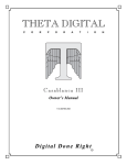
Speaker placement
ENGLISH
Ideal speaker placement varies depending on the size of your room
and the wall coverings, etc. The typical example of speaker placement
and recommendations are as follows :
■Front left and right speakers and center speaker
• Place the front speakers with their front surfaces as flush with TV or
monitor screen as possible.
• Place the center speaker between the front left and right speakers and
no further from the listening position than the front speakers.
• Place each speaker so that sound is aimed at the location of the
listener’s ears when at the main listening position.
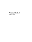
■Surround left and right speakers
• Place the surround speakers approximately 1 meter(40 inches) above
the ear level of a seated listener on the direct left and right of them or
slightly behind.
■Surround back left and right speakers
• Place the surround back speakers at the back facing the front at a
narrower distance than front speakers.
• When using a single surround back speaker, place it at the rear center
facing the front at a slightly higher position(0 to 10 inches ) than the
surround speakers.
• We recommend installing the surround back speaker at a slightly
downward facing angle. This effectively prevents the surround back
channel signals from reflecting off the TV or screen at the front center,
resulting in interference and making the sense of movement from the
front to the back less sharp.
1. TV or screen
2. Front left speaker
3. Subwoofer
4. Center speaker
5. Front right speaker
6. Surround left speaker
Surround speaker
7. Surround right speaker
8. Surround back left speaker
9. Surround back right speaker
10. Surround back center speaker
11. Listeing position
Surround back
speaker
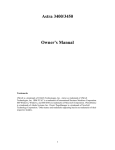
■Subwoofer
Point slightly
downward
Front speaker
• The subwoofer reproduces powerful deep bass sounds.
Place a subwoofer anywhere in the front as desired.
■Notes :
• When using a conventional TV, to avoid interference with the TV
picture, use only magnetically shielded front left and right and center
speakers.
• To obtain the best surround effects, the speakers except the
subwoofer should be full range speakers.
9
60 to 90 cm
7. CONNECTING SYSTEM CONTROL
• Connect this jack to the DIGI LINK jack of the external
Sherwood component that uses the DIGI LINK II or III
remote control system.
Sherwood component
with DIGI LINK II or III
DIGI-LINK
ENGLISH
CD player
Tape deck
System
control
cord
DVD player
8. CONNECTING DC TRIGGER OUTs
• Connect components that need to be triggered by DC
under certain conditions as follows :
• Connect a component to DC TRIGGER OUT 1 jack that
Component such as
Sherwood A-965 to be
allows DC 12 V to turns on or off when this unit’s power is
triggered by DC when this
turned on or off.
unit's power is turned on
In case that this unit is connected to Sherwood power
Component to be triggered
amplifier A-965, connect DC TRIGGER IN jack of A-965
by DC when a specific input
1
2
to DC TRIGGER OUT 1 jack for system power control.
source is selected
DC TRIGGER OUT
12V d.c. 100 A
• Connect a component to DC TRIGGER OUT 2 jack that
allows DC 12 V to turn on or off when a specific input
source is selected or not.
• For details, refer to the operating instructions of the
components to be connected .
• To link DC TRIGGER OUT 2 with a specific input source, refer to “When selecting the DC TRIGGER 2 SETUP” on page 55.
mm
Notes :
• This output voltage (12 V d.c., 100mA ) is for (status) control only , it is not sufficient for drive capability.
• When making DC TRIGGER connection, you should use the stereo mini cord, not a mono mini cord.
ROOM 2 connections
• ROOM 2 playback feature allows you to play a different program source in another room as well as one source in the main
room at the same time.
• For ROOM 2 playback, connect the VIDEO 2 / ROOM 2 OUT jacks and the COAXIAL DIGITAL OUT to the amplifier, TV. etc.
installed in another room.
Note :
• To minimize hum or noise, use high quality connection cords.
Main room
Another room(Room 2)
This unit
OUT
VIDEO2/
ROOM2
OUT
IN
S-VIDEO
IN
VIDEO
TV or projector
L AUDIO
IN
R
COAXIAL
DIGITAL IN
Amplifier
10
Speakers
• The multi-room system kit(sold separately ) is essential for operation from a remote location .
For information on the multi-room system kit, contact the Xantech corporation at 1-800-843-5465 or www.xantech.com.
• IR IN jacks allow you to control this unit from another room with the remote control unit.
• To control this unit from another room with the remote control unit, connect the IR IN 1 or 2 jack to the output of the
connecting block.
• If this unit is located inside a cabinet or other enclosure where the infrared beams from the remote control unit cannot enter,
then operation with the remote control unit will not be possible. In such a case, connect the IR IN 1 or 2 jack to the output of
the connecting block.
• To control other compatible component from another room with the universal remote control unit, connect the IR OUT jack to
the IR emitter.
Another room(Room 2)
Main room
Connecting block
(Multi-room system kit)
output
IR receiver
(Multi-room system kit)
IN1
IN2
OUT
IR
This unit
DVD player
MASTER VOLUME
MULTI
MUL
TI CONTROL
INPUT SELECTOR
POWER
STANDBY
ON/
DECODING
STEREO
DIGITAL/ANALOG
PURE AUDIO
VIDEO
AUDIO
T.MON
8CH DIRECT
OFF
W R A S
-965
A/V TUNER AMPLIFIER P
P-965
WIDE RANGE AMPLIFIER STAGE
IR emitter
(Multi-room system kit)
• When this unit is located inside a cabinet.
In the cabinet
Connecting block
(Multi-room system kit)
IN1
IN2
OUT
IR
This unit
MASTER VOLUME
MULTI
MUL
TI CONTROL
INPUT SELECTOR
POWER
STANDBY
ON/
W R A S
WIDE RANGE AMPLIFIER STAGE
DECODING
STEREO
DIGITAL/ANALOG
PURE AUDIO
VIDEO
AUDIO
T.MON
8CH DIRECT
OFF
-965
A/V TUNER AMPLIFIER P
P-965
11
RNC-500
output
IR receiver
(Multi-room system kit)
ENGLISH
9. CONNECTING MULTI-ROOM SYSTEM KIT
ENGLISH
10. CONNECTING PC FOR UPGRADES
• This unit incorporates USB as well as RS-232C terminal
that may be used in the future to update the operating
software so that it will be able to support new digital audio
formats and the like.
• Connect either USB or RS-232C terminal to your PC(You
don’t need to do both).
RS-232C
USB
PC with USB
or RS-232C port
OPR.
SVC.
UPGRADE switch
RS-232C connections for external control
• RS-232C terminal is also to be used in conjunction with
an external controller to control this unit by using an
external device.
Notes :
• Be sure to set the UPGRADE switch to “SVC”(service) before updating.
• This switch should be set to “OPR”(operation) during normal operation except for upgrades.
If not, this unit will not operate normally.
• Programming for upgrades and external control requires specialized programming knowledge and for that reason we
recommend that it only be done by qualified installers. For more information on future upgrades and external control, visit the
Sherwood web site at www.sherwoodamerica.com or contact your dealer.
• Do not disconnect the connection cable while updating the operating software, etc.
Should this happen, it may be result in malfunction or cause damage to the unit.
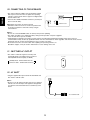
11. SWITCHED AC OUTLET
• This outlet is switched on(power-on mode) and
off(standby mode) according to power control as
follows(Maximum total capacity is 100 W).
AC OUTLET
Standby mode - Switched AC outlet off
Power-on mode - Switched AC outlet on
12. AC INLET
• Plug the supplied AC input cord into this AC INLET and
then into the wall AC outlet.
Note:
• Do not use an AC input cord other than the one supplied
with this unit. The AC input cord supplied is designed for
use with this unit and should not be used with any other
device.
To a wall AC outlet.
12
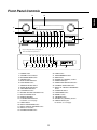
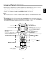
Front Panel Controls
14
ENGLISH
13
MASTER VOLUME
MULTI CONTROL
12
11
INPUT SELECTOR
POWER
STANDBY
DECODING
STEREO
DIGITAL/ANALOG
PURE AUDIO
VIDEO
AUDIO
T.MON
8CH DIRECT
1
ON/
OFF
15
A/V TUNER PRE AMPLIFIER P-965
2
3
4
5
6
7
20
21
22
23
8
9
10
• To open the panel door, push gently on
the lower third of the panel door.
16
17 18
H
VS
CH.SEL
19
PLIIx
PLII MUSIC
PARAMETER
DYNAMIC RANGE
LABEL
ENTER/MEMO
BAND
TUNE
+
CINEMA EQ
TONE MODE
ROOM2
FM MODE
PRESET
+
VIDEO 6
PHONES
OPTICAL IN5
24
25
26
27
28
29
30
1. POWER switch
2. STANDBY button/indicator
3. DECODING MODE button
4. STEREO button
5. DIGITAL/ANALOG button
6. PURE AUDIO button
7. VIDEO SELECTOR button
8. AUDIO SELECTOR button
9. TAPE MONITOR button
10. 8 CH DIRECT button
11. MASTER VOLUME CONTROL knob
12. MULTI CONTROL knob
13. REMOTE SENSOR
14. FLUORESCENT DISPLAY
For details, see next page.
15. PANEL DOOR
16. DOLBY HEADPHONE button
17. DOLBY VIRTUAL SPEAKER button
18. DOLBY PL IIx button
19. DYNAMIC RANGE button
31
32
S-VIDEO
VIDEO
L
AUDIO
R
33
20. LABEL button
21. ENTER/MEMORY button
22. BAND button
23. TUNING UP(+)/DOWN(-) buttons
24. HEADPHONE jack
25. HEADPHONE SELECTOR button
26. CHANNEL SELECTOR button
27. DOLBY PL II MUSIC PARAMETER
button
28. CINEMA EQ button
29. TONE MODE button
30. ROOM 2 button
31. FM MODE button
32. PRESET UP(+)/DOWN(-) buttons
33. VIDEO 6 INPUT jacks
For details, see next page.
13
FLUORESCENT DISPLAY
ENGLISH
1
2
3
4
5
6 7 8
DOLBY H DIGITAL EX VIRTUAL DIRECT AUTO
L
C
R
PCM PRO LOGIC
MPEG PURE
SOUND TAPE MON STEREO
ANALOG
DIGITAL
RE-MASTERING
3
9
DTS ES 96/24 NEO:6
RDS EON TA PTY
Z
TUNED TP PRESET
VIDEO SET
123456
R2 MUTE
CINE-EQ
MEMORY
20
21
22
23
AP-SW
24
SL SW SR
LFE
SB
12
11
13
14
1. CHANNEL indicators
2. PCM SIGNAL indicator
3. SURROUND MODE indicators
4. TAPE MONITOR indicator
5. DIRECT indicator
6. STEREO indicator
7. AUTO indicator
8. RDS indicators
9. SLEEP indicator
10. VIDEO INPUT indicators
11. MPEG SIGNAL indicator
12. PURE AUDIO indicator
13. ANALOG INPUT indicator
15
16
17
18
10
19
14. DIGITAL INPUT indicator
15. Input, frequency, volume level, operating
information, etc.
16. RE-MASTERING indicator
17. TUNED indicator
18. PRESET indicator
19. ROOM 2 indicator
20. MUTE indicator
21. CINEMA EQ indicator
22. MEMORY indicator
23. SPEAKER indicator
24. SUBWOOFER indicators
VIDEO 6 INPUT JACKS
VIDEO 6
OPTICAL IN5
OPTICAL
DIGITAL IN
S-VIDEO
S-VIDEO
IN
VIDEO
VIDEO
IN
L - AUDIO - R
• The VIDEO 6 input jacks may be also connected to an
additional video component such as a camcorder, a
video game player, etc.
• If the OPTICAL IN 5 is connected to the component
connected to VIDEO 6, it is easier to do so following the
default settings.(For details, refer to “Digital input default
settings” on page 7.)
• If the OPTICAL IN 5 connection is different from the
default settings, you should assign the DIGITAL INs you
used with the “When selecting the DIGITAL INPUT
SETUP” procedure on page 51.
L R
AUDIO IN
VIDEO 6 Camcorder, video game player, etc.
14
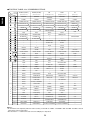
This universal remote control can operate not only this unit but also most popular brands of audio and video components
such as CD players, DVD players, tape decks, TVs, VCRs, satellite units, cable boxes, etc.
• To operate 8 components other than this unit, you should enter the setup code for each component.
(For details, refer to “ENTERING A SETUP CODE” on page 19)
• The numbered buttons on the remote control have different functions in different device modes.
For details, refer to “FUNCTION TABLE of the NUMBERED BUTTONS” on the next page.
Note :
• This section explains the basic operations to control this unit and other Sherwood components with this remote control.
For various and convenient functions of this remote control, refer to the operating manual inclosed with this remote control.
DIGI LINK system remote controls
This remote control can also operate Sherwood compatible components bearing the DIGI LINK(II or III) logo.
• For DIGI LINK system remote control operation, first make the DIGI LINK connections between Sherwood components.
• In the DIGI LINK III remote control system, if pressing PLAY, etc. on CD player or tape deck, CD or TAPE MONITOR is
selected automatically on the unit without selecting the input source. Then PLAY, etc. starts.
POWER ON
STANDBY
STANDBY button
POWER ON button
MAIN
AUD1 AUD2
LCD(FUNCTION) buttons
CD
SAT
AUX
Enters the MAIN menu mode.
Activates the backlighting of the remote control
for a specified time(up to 99 sec.) If any other
button is pressed while the backlighting is on,
the remote control will remain backlit for an
additional period.
VCR
TAPE
MAIN button
LIGHT button
TV
DVD
CABLE
AUD1
LCD(FUNCTION) buttons
PAGE button
While displaying the page menu of the
selected device or the favorite channel menu,
each time this button is pressed, its page changes.
VOLUME UP/DOWN( / ) buttons
PA GE
LCD SCREEN
FAV
MAIN
FAVORITE button
Enters the favorite channel mode.
Each time this button is pressed, its page changes.
CH.
SEL
CH/
VOL
ADJUST
MUTE
DECODE
DSP
CHANNEL LEVEL / ADJUST
UP/DOWN( / ) buttons
DSP
CURSOR CONTROL(
ENTER( ) buttons
RETURN
STEREO
NUMERIC(1~0) buttons
1
2
3
4
5
6
7
8
9
OSD/MENU
MACRO buttons
To operate a macro function,
press the corresponding
MACRO button.
DISP
0
ENT
MI
M2
M3
RNC-510
15
),
ENGLISH
Universal Remote Controls
FUNCTION TABLE of the NUMBERED BUTTONS.
Device to
be controlled
Button
symbol
AUDIO 1("AUD1")
AUDIO 2("AUD2")
CD
TAPE
TV
(for receiver, "001")
(for receiver, "001")
(for CD player, "001")
(for tape deck, "001")
(for TV, "001")
POWER ON
POWER ON
<POWER ON>
<POWER ON>
POWER ON
STANDBY
STANDBY
<STANDBY>
<STANDBY>
STANDBY
ENGLISH
POWER ON
STANDBY
CHANNEL SELECTOR
CHANNEL SELECTOR
CH.
SEL
CH LEVEL/ADJUST UP(
)
CH LEVEL/ADJUST UP(
<CHANNEL SELECTOR>
)
<CH LEVEL/ADJUST UP(
PREVIOUS CHANNEL
<CHANNEL SELECTOR>
)> <CH LEVEL/ADJUST UP(
)>
CHANNEL UP(
)
CH/
ADJUST
CH LEVEL/ADJUST DOWN( ) CH LEVEL/ADJUST DOWN( ) <CH LEVEL/ADJUST DOWN( )> <CH LEVEL/ADJUST DOWN( )>
CHANNEL DOWN(
VOLUME UP( )
VOLUME UP( )
<VOLUME UP( )>
<VOLUME UP( )>
VOLUME UP( )
VOLUME DOWN( )
VOLUME DOWN( )
<VOLUME DOWN( )>
<VOLUME DOWN( )>
VOLUME DOWN( )
MUTE
MUTE
<MUTE>
<MUTE>
MUTE
DECODING MODE
DECODING MODE
PLAY
FORWARD PLAY
-
)
VOL
MUTE
DECODE
DSP
DSP MODE UP( )
DSP MODE UP( )
-
-
SURROUND MODE
DSP MODE DOWN( )
DSP MODE DOWN( )
-
-
-
-
-
FORWARD SKIP
FAST FORWARD
-
-
-
REVERSE SKIP
REWIND
-
-
-
PAUSE
PAUSE
-
RETURN
RETURN
-
RECORD
-
DSP
RETURN
STEREO
STEREO
STOP
STOP
LANGUAGE
CURSOR CONTROL
CURSOR CONTROL
<CURSOR CONTROL>
<CURSOR CONTROL>
CURSOR CONTROL
ENTER
ENTER
<ENTER>
<ENTER>
ENTER
0~9
STEREO
0~9
0~9
0~9
0~9
DISPLAY
DISPLAY
<DISPLAY>
<DISPLAY>
-
OSD
OSD
<OSD>
<OSD>
MENU
(Left 1)
TUNER
SLEEP
PLAY
DECK SELECTOR A
-
(Left 2)
CD
DIMMER
REVERSE SKIP
REVERSE PLAY
SLEEP
(Left 3)
TAPE MONITOR
ROOM 2
STOP
RECORD
CAPTION
(Left 4)
AUX
TEST TONE
REPEAT A< >B
REWIND
-
(Left 5)
PHONO
OSD
-
STOP
-
(Right 1)
VIDEO 1
DIGITAL/ANALOG
PAUSE
DECK SELECTOR B
-
0
9
DISP
OSD/MENU
ENT
P
A
G
E
(Right 2)
VIDEO 2
SURROUND A/B
FORWARD SKIP
FORWARD PLAY
AUTO SET
(Right 3)
VIDEO 3
SURROUND BACK
INTRO SCAN
PAUSE
ADD/ERASE
(Right 4)
VIDEO 4
PURE AUDIO
-
FAST FORWARD
-
(Right 5)
VIDEO 5
PL II MUSIC PARAMETER
-
-
-
(Left 1)
VIDEO 6
SEARCH MOE
<SLEEP>
<SLEEP>
PIP
(Left 2)
DTS
PTY SELECT
<DIMMER>
<DIMMER>
SWAP
(Left 3)
DOLBY DIGITAL
MEMORY
<ROOM 2>
<ROOM 2>
SOURCE
1
P
A
G
E
2
(Left 4)
PCM
TUNING UP(+)
<TEST TONE>
<TEST TONE>
-
(Left 5)
MPEG
TUNIGN DOWN(-)
<OSD>
<OSD>
-
(Right 1)
8 CH DIRECT("7.1 IN")
EON TA
<DIGITAL/ANALOG>
<DIGITAL/ANALOG>
-
(Right 2)
PL II MOVIE
EON PTY
<SURROUND A/B>
<SURROUND A/B>
STILL
(Right 3)
PL II MUSIC
PRESET SCAN
<SURROUND BACK>
<SURROUND BACK>
-
(Right 4)
NEO 6 CINEMA
PRESET UP(+)
<PURE AUDIO>
<PURE AUDIO>
-
(Right 5)
NEO 6 MUSIC
PRESET DOWN(-)
<PL II MUSIC PARAMETER> <PL II MUSIC PARAMETER>
-
Notes :
• To control this unit completely with this remote control, you should use “AUD 1” and “AUD 2” both and “001” should be entered
respectively as their setup codes.
• The functions in < > work for this unit, not for the CD player or tape deck.
16
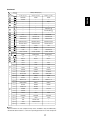
Continued
Device to
be controlled
Button
symbol
DVD(for DVD player)
V-768, etc.("001")
VD-4106, etc.("091")
VD-8300, etc.("116")
POWER ON
POWER
POWER
STANDBY
-
-
-
-
DIGEST
-
-
-
-
-
-
-
VOLUME UP(
-
-
VOLUME DOWN(
-
-
-
PLAY
PLAY
PLAY/PAUSE
FORWARD SKIP
FORWARD SKIP
FORWARD SKIP
REVERSE SKIP
REVERSE SKIP
REVERSE SKIP
FORWARD SEARCH
FORWARD SEARCH
FORWARD SEARCH
REVERSE SEARCH
REVERSE SEARCH
REVERSE SEARCH
STEP
ENGLISH
POWER ON
STANDBY
CH.
SEL
CH/
ADJUST
)
VOL
MUTE
DECODE
)
DSP
DSP
PAUSE
PAUSE
RETURN
RETURN
-
STOP
STOP
STOP/RETURN
CURSOR CONTROL
CURSOR CONTROL
CURSOR CONTROL
ENTER
ENTER/SELECT
ENTER/SELECT
0~9
0~9
0~9
DISPLAY
DISPLAY
DISPLAY
MENU
-
-
SETUP
SETUP
SETUP
RETURN
STEREO
0
9
DISP
OSD/MENU
ENT
(Left 1)
(Left 2)
TITLE
TITLE
TITLE
(Left 3)
AUDIO
AUDIO
AUDIO
(Left 4)
SUBTITLE
SUBTITLE
SUBTITLE
P
A
(Left 5)
DISC SKIP
SOUND
3D SOUND
(Right 1)
OPEN/CLOSE
OPEN/CLOSE
OPEN/CLOSE
(Right 2)
ZOOM
ZOOM
ZOOM
G
E
1
P
A
G
E
2
(Right 3)
SEARCH
SEARCH
PBC
(Right 4)
REPEAT A< >B
REPEAT A< >B
REPEAT A< >B
(Right 5)
REPEAT MODE
REPEAT
REPEAT
(Left 1)
MARKER
MARKER
MARKER
(Left 2)
INTRO SCAN
RESUME
-
(Left 3)
RANDOM
RANDOM
SHUFFLE
(Left 4)
SUBTITLE
-
-
(Left 5)
ANGLE
ANGLE
ANGLE
(Right 1)
PROGRAM
PROGRAM
PROGRAM
(Right 2)
CLEAR
CLEAR
CLEAR
(Right 3)
TIME
REVERS SLOW
-
(Right 4)
SLOW
FORWARD SLOW
-
(Right 5)
PAL/NTSC
-
-
Notes :
• Some functions for each component may not be available or may work differently .
• For details about functions , refer to the operating instructions of each component .
17
ENGLISH
OPERATING COMPONENTS WITH REMOTE CONTROL
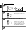
REMOTE CONTROL OPERATION RANGE
Enter the setup code of the components
respectively, referring to “ENTERING A
SETUP CODE” (page 19).
1
• Use the remote control within a range of about 7
meters (23 feet) and angles of up to 30 degrees
aiming at the remote sensor.
Turn on the components you want to
operate.
2
MASTER VOLUME
MULTI CONTROL
INPUT SELECTOR
POWER
STANDBY
ON/
DECODING
STEREO
DIGITAL/ANALOG
PURE AUDIO
VIDEO
Select the device on the main menu of the
remote control corresponding to the
component you want to operate.
3
AUDIO
T.MON
8CH DIRECT
OFF
-965
A/V TUNER PRE AMPLIFIER P
P-965
Example) When selecting “AUD 1” or “AUD 2” to
operate this unit.
POWER ON
STANDBY
POWER ON
STANDBY
MAIN
AUD1 AUD2
PAGE
FAV
MAIN
CH.
SET
CH/
VOL
ADJUST
MUTE
DECODE
CD
DSP
TV
DVD
DSP
VCR
TAPE
RETURN
SAT
STEREO
1
4
AUX
CABLE
AUD1
7
2
5
8
3
6
9
OSD/MENU
The device selected presently
DISP
0
ENT
MI
M2
M3
RNC-510
• Then the page menu of the selected device will be
displayed.
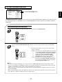
LOADING BATTERIES
Press the button corresponding to the
operation you want while aiming the
remote control at the REMOTE SENSOR
on the component.
4
When the remote control does not operate or “LOW
BATTERY” is displayed on the LCD screen, etc., the old
batteries should be replaced.
• When operating a Sherwood CD player or tape deck
using the system remote control, aim the remote
control at the REMOTE SENSOR on this unit.
• However, in case of Sherwood DVD player or TV,
aim it at the REMOTE SENSOR on the
corresponding component.
■In case of selecting a function on the page menu of
the selected device.
• Find a function with pressing the PAGE button
repeatedly and then press the button corresponding
to the desired function.
Example) when selecting a function on the AUD 1’s
page menu.
Functions on the page 1
AUD1
1
2
Functions on the page 2
AUD1
TUNER
VID1
VID6
7.1IN
CD
VID2
DTS
PL2MV
T.MON
VID3
DOLBY PL2MS
AUX
VID4
PCM
PHONO
VID5
MPEG
PAGE1
NOE6C
NEO6M
PAGE2
18
Remove the cover.
Load four alkaline batteries (“AAA” size.
1.5V) matching the polarity.
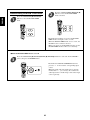
• This remote control can control up to ten different components.
• Before operating audio and video components using the remote control supplied with this unit, the setup code for each
component should be entered.
• For system remote control operation between Sherwood components, “001” was stored previously in the memory of each
device such as “AUD 1” and “AUD 2” for this unit, “CD” for CD player, “TAPE” for tape deck , “TV” for TV and “DVD” for DVD
player.
So, you don’t need to enter its code for each Sherwood component except in such a case that its code does not work.(When
entering each setup code for Sherwood CD player and tape deck , do from the below step ③.)
Turn on the component you want to control.
2
1
Example) When entering the setup code for this unit,
turn on this unit.
■Note:
If your component has the discrete POWER ON and OFF
buttons, please do not turn on the component manually.
3
Find the setup code for your component
referring to “Set-Up Code Table” in the
operating manual of this remote control.
Example) The 3 digit setup codes for the Sherwood
“Audio” are 001,024, ...(Hint:The correct
setup code for this unit is “001”.)
Press both the MAIN and OSD/MENU
(/ENTER) buttons simultaneously for 3
seconds.
Select the Pre-PROgramming mode.
4
POWER ON
STANDBY
POWER ON
STANDBY
MAIN
PAGE
SETUP
FAV
MAIN
CH.
SET
CH/
VOL
P-PRO
LEARN
FAV
MACRO
PUNCH
RECAL
ADJUST
MUTE
DECODE
DSP
DSP
ERASE
EDIT
LIGHT
CLONE
RETURN
STEREO
1
4
7
2
5
8
3
6
OSD/MENU
9
OSD/MENU
DISP
0
ENT
MI
M2
M3
ENT
RNC-510
Then the setup menu will be displayed on the LCD
screen.
■Note:
If the display of the corresponding mode disappears,
start again from the above step ③ or the current mode.
5
Then the Pre-PROgramming menu will be displayed.
Select the device corresponding to the
component you want to control.
Example) When selecting the “AUD 1” for
unit or amplifier, etc.
6
Select the device from which the appropriate
3 digit setup code table will be selected.
Example) If it is the “AUD 1” code table,
select the “AUD 1” .
POWER ON
STANDBY
POWER ON
STANDBY
P-PRO
AUD1
CD
AUD1
AUD1
AUD2
AUD1
TV
DVD
VCR
TAPE
SAT
AUD2
CD
DVD
CABLE
SELECT
AUX
SAT
EXIT
CABLE
TABLE
19
SAVE
VCR
TAPE
AUX
001
TV
DOWN
UP
ENTER
ENGLISH
ENTERING A SETUP CODE
Enter the 3 digit setup code aiming the
remote control at the REMOTE SENSOR on
the component.
ENGLISH
7
8
Confirm that it is the right code by selecting
the SAVE.
POWER ON
STANDBY
AUD 1
001
SAVE
EXIT
DOWN
POWER ON
STANDBY
UP
ENTER
PAGE
AUD 1
FAV
MAIN
001
SAVE
CH.
SET
CH/
VOL
ADJUST
MUTE
DECODE
DSP
DSP
EXIT
For "001" :
0
0
1
DOWN
RETURN
STEREO
1
2
4
5
7
8
3
UP
ENTER
6
9
OSD/MENU
DISP
MI
0
ENT
M2
M3
For "102" :
1
0
2
RNC-510
Your component will be turned off when the right
code is entered.
Continue to enter the corresponding codes until your
component turns off.
The code is saved and the Pre-PROgramming mode
is resumed.
When you do not want to save the code, select the
EXIT on the LCD screen or press the MAIN button.
To resume the MAIN menu mode, press the
MAIN button twice briefly.
9
10
If any of the buttons fails to operate as they should,
start from the step ① again to enter the next setup code.
■Notes:
If the Manufacturer/Brand for your component is not
listed in “Set-Up Code Table” in the operating manual
of this remote control, please use the “ 2 Auto Scan
Method” on page 13 in the operating manual of this
remote control.
Although each setup code is designed to work with
many different modes, certain codes may not work
with some models.( Also, certain codes may only
operate some of the functions available on a given
model.)
POWER ON
STANDBY
MAIN
PAGE
FAV
MAIN
CH.
SET
CH/
VOL
ADJUST
MUTE
DECODE
DSP
DSP
RETURN
STEREO
1
2
4
5
7
8
3
6
9
OSD/MENU
DISP
0
ENT
MI
M2
M3
The selected device
RNC-510
Each time the MAIN button is pressed, the previous
mode is resumed.
11
Operate the component using the
corresponding function buttons.
Repeat the above steps ① to ⑩ for each of your other components.
20
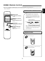
This remote control unit is an additional remote control unit for the ROOM 2 source playback only.
• You can use the ROOM 2 functions with this remote control unit more conveniently in another room than with the universal
remote control unit.
REMOTE CONTROL OPERATION RANGE
• Aim the ROOM 2 remote control(or the
universal remote control) at the IR receiver
installed in another room.(For details, refer to
“CONNECTING MULTI-ROOM SYSTEM
KIT” on page 11.)
ROOM2
ROOM 2 BUTTON
PHONO
CD
TUNER
VIDEO 1
VIDEO 2
VIDEO 3
VIDEO 4
VIDEO 5
VIDEO 6
AUX
Each time this button is pressed,
the ROOM 2 function is activated or
canceled.
AUDIO
ROOM 2 INPUT SELECTOR
BUTTONS
When one of these buttons is pressed,
the corresponding input source is
selected.
Another room(Room 2)
To main room
MUTE BUTTON
IR receiver
(Multi-room system kit)
Mutes the sound of the ROOM2 source.
•To resume the previous sound level,
press it again.
MUTE
VOLUME
VOLUME UP/DOWN(
BUTTONS
• When you operate the ROOM 2 function in the
main room, aim the universal remote control(or
the ROOM 2 remote control) at the remote
sensor of this unit.
)
Adjust the sound volume of the
ROOM 2 source.
LOADING BATTERIES
1
2
21
Remove the cover.
Load two batteries (“AAA” size, 1.5V )
matching the polarity.
ENGLISH
ROOM 2 Remote Controls
ENGLISH
Operations
Notes : • Before operating this unit with the supplied remote control, refer to “ Universal Remote Controls” on page 15 for details
about operation.
• Before operating this unit, first set this unit as desired for optimum performance, doing the OSD menu setting procedures.
(For details, refer to “OSD Menu Settings” on page 44.)
LISTENING TO A PROGRAM SOURCE
Select the desired input source.
Before operation
• Enter the standby mode.
3
POWER
• The STANDBY button lights up in amber.
This means that the unit is not
disconnected from the AC mains and a
small amount of current is retained to
support the memorized contents and
operation readiness.
• To switch the power off, push the POWER switch again.
• Then power is cut off and the STANDBY button goes off.
ON /
CH.
SET
CH/
ADJUST
DECODE
or
DSP
STEREO
4
7
2
5
8
3
6
9
OSD/MENU
DISP
0
ENT
MI
M2
M3
VID3
AUX
VID4
PHONO
VID5
PAGE1
TAPE MONITOR function
You can connect either a tape deck or a graphic equalizer to the
unit’s TAPE MONITOR jacks.
Only when you listen to the component connected to these
jacks, set the TAPE MONITOR button to on.
If you connect a 3-head tape deck, you can listen to the sound
being recorded during recording, not the source sound.
For further details, refer to the operating instructions of the
component connected.
RETURN
1
VID2
T.MON
• When the TAPE MONITOR button is set to on so that
“TAPE MON” lights up, other inputs can not be heard
from the speakers.
To listen to an input source except TAPE MONITOR, be sure
to set the TAPE MONITOR button to off.
FAV
MAIN
CD
• Each time the “VIDEO” button is pressed, the input
source changes as follows:
VIDEO 1 VIDEO 2 ------VIDEO 6
MUTE
DSP
VID1
(frequency display)
STANDBY
VOL
AUD1
TUNER
• Each time the “AUDIO” button is pressed, the input
source changes as follows:
PHONO
TUNER
CD
AUX
POWER ON
PAGE
POWER ON
STANDBY
T.MON
or
POWER ON
STANDBY
STANDBY
AUDIO
OFF
In the standby mode, turn the power on.
1
INPUT SELECTOR
VIDEO
RNC-510
• Each time the STANDBY button on the front panel
is pressed, the unit is turned on to enter the
operating mode (the STANDBY button lights up in
blue) or off to enter the standby mode(the
STANDBY button lights up in amber).
• On the remote control, press the POWER ON button
to enter the operating mode or press the STANDBY
button to enter the standby mode.
• In the standby mode if the INPUT SELECTOR
button is pressed, the unit is turned on automatically
and the desired input is selected.
When selecting the 8 CH DIRECT as desired
POWER ON
STANDBY
8CH DIRECT
AUD1
VID6
or
7.1IN
DTS
PL2MV
DOLBY
PL2MS
PCM
NEO6C
MPEG
NEO6M
PAGE2
Switch the speakers on.
• Depending on the surround back speaker setting, “8(, 7 or
6) CH DIRECT” is displayed and the 8(/7/6) separate
analog signals from the component connected to this input
pass through the tone, volume and bass management(if
selected) circuits only and can be heard from your
speakers.(In case that the TAPE MONITOR button is set to
on, the TAPE MONITOR button is automatically set to off.)
• Press the 8 CH DIRECT button or select the desired input
source to cancel the 8 CH direct function.
• These analog signals can be heard only. They cannot be
recorded.
2
• Then the SPEAKER indicator ( ) lights up and the
sound can be heard from the speakers.
• When using the headphones for private listening,
press this button again to switch the speakers off,
then the SPEAKER indicator ( ) goes off(speaker
off mode).
22
When CD, AUX or VIDEO 1~ VIDEO 6 is
selected
Select the tone mode as desired.
7
Select the digital or the analog input as
desired.
TONE MODE
POWER ON
STANDBY
ENGLISH
4
Adjusting the tone (bass and treble)
DIGITAL/ANALOG
AUD2
SLEEP
or
D/A
DIMM
S.A/B
ROOM2
SUR.B
T.TON
PURE
OSD
PARA.
PAGE1
• Each time this button is pressed, the corresponding
input is selected as follows:
DIGITAL
• Each time this button is pressed, the tone mode
changes as follows:
BASS
TREBLE DEFEAT OFF(or ON)
ANALOG
• The tone display is shown for several seconds.
• If the tone display disappears, press the TONE
MODE button again.
• ( ) : When the tone defeat function is activated
(“DEFEAT ON”), bass and treble modes
cannot be selected
■Note:
• When the pure audio function is activated, the tone
mode cannot be selected.
• When PHONO, TUNER or TAPE MONITOR is
selected as an input source, the analog input is
automatically selected.
■Notes:
• When the selected digital input is not connected,
“DIGITAL” is flickering, meaning no sound.(Refer
to “ENJOYING SURROUND SOUND” on page
28.)
• To select the digital input, you should assign the
connected DIGITAL IN to the corresponding input
source. (For details, refer to “When selecting the
DIGITAL INPUT SETUP” on page 51.)
8
At the desired tone mode, adjust as
desired.
MULTI CONTROL
5
Operate the selected component for
playback.
■At the tone defeat mode, each time the MULTI
CONTROL knob is rotated, the tone defeat mode
changes as follows:
• When playing back the program sources with
surround sound, refer to “ENJOYING SURROUND
SOUND” on page 28.
DEFEAT ON : When listening to a program source
↕
without the tone effect.
DEFEAT OFF : When adjusting the tone for your taste.
Adjust the (overall) volume.
6
■At the desired tone (bass or treble), each time the
MULTI CONTROL knob is rotated, the tone level
can be adjusted within the range of +10~ -10 dB.
• In general, we recommend the bass and treble to be
adjusted to 0(flat) level.
• To complete tone adjustment, repeat the above steps
⑦ and ⑧.
• Extreme settings at high volume may damage your
speakers.
POWER ON
STANDBY
MASTER VOLUME
PAGE
FAV
MAIN
CH.
SET
or
VOL
CH/
VOL
ADJUST
MUTE
DECODE
DSP
DSP
RETURN
STEREO
1
DOWN
UP
2
4
5
7
8
3
6
9
OSD/MENU
DISP
0
ENT
MI
M2
M3
RNC-510
23
ENGLISH
Achieving higher purity of sound quality
Compensating for edgy or shrill movie
sound tracks
POWER ON
STANDBY
PURE AUDIO
AUD2
SLEEP
or
S.A/B
ROOM2
SUR.B
T.TON
PURE
OSD
CINEMA EQ
D/A
DIMM
PARA.
PAGE1
• Only when playing program sources recorded in
either analog stereo or 2 channel PCM format, the
pure audio function can be selected.
• “PURE” lights up and the stereo mode is
automatically selected and all the video-related
circuits as well as the digital processing circuits are
turned off.
• Press this button again to cancel the pure audio
function.
• When you select other input source or the other
between digital and analog inputs, the pure audio
function is automatically canceled.
• When 96 kHz PCM(2 channel stereo) signals are
input or the pure audio function is selected, the
cinema EQ function can not be selected.
• “CINEMA-EQ ON” will scroll on the display.
• Press it again to cancel, then “CINEMA-EQ OFF”
will scroll on the display.
Muting the sound
Listening with the headphones
POWER ON
STANDBY
PHONES
PAGE
MUTE
FAV
MAIN
CH.
SET
CH/
VOL
ADJUST
MUTE
DECODE
DSP
DSP
RETURN
STEREO
1
2
4
5
7
8
3
6
9
OSD/MENU
DISP
0
ENT
MI
M2
M3
RNC-510
• Ensure that the HEADPHONE SELECTOR button is
set to the speaker off mode.
• Depending on the signal format which is being input,
you can listen in different Dolby Headphone modes,
stereo mode, etc. with pressing the DOLBY
HEADPHONE button. (For details, refer to
“Listening in a Dolby Headphone mode” on page 30).
• “MUTE” lights up.
• To resume the previous sound level, press the button
again.
24
SURROUND SOUND
Surround modes
■DTS Digital Surround
DTS Neo : 6 Cinema
This mode is optimum for playing movies. Decoding is
performed with emphasis on separation performance to
achieve the same atmosphere with 2-channel sources as with
6.1-channel sources.
DTS Digital Surround(also called simply DTS) is a multichannel digital signal format which can handle higher data
rates than Dolby Digital. Although both Dolby Digital and DTS
are 5.1 channel formats, discs bearing the “
” are
generally thought to provide better sound quality due to the
lower audio compression required.
It also provides wide dynamic range and separation, resulting
in magnificent sound.
■DTS - ES Extended Surround™
(
DTS Neo : 6 Music
This mode is suited mainly for playing music. The front left
and front right signals bypass the decoder and are played
directly so there is no loss of sound quality, and the effect of
the surround signals from the center, surround left, surround
right and surround back channels adds a natural sense of
expansion to the sound field.
)
This is a new multi channel digital signal format which greatly
improves the 360- degree surround impression and space
expression thanks to further expanded surround signals,
offering high compatibility with the conventional DTS format.
In addition to the 5.1 channels, DTS-ES Extended Surround
also offers the surround back (sometimes also referred to as
“surround center”) channel for surround playback with a total
of 6.1 channels. DTS-ES Extended Surround includes two
signal formats with different surround signal recording
methods as follows:
■DTS 96/24
Conventional surround formats used sampling frequencies of
48 or 44.1 kHz, so 20 kHz was about the maximum playback
signal frequency. With DTS 96/24, the sampling frequency is
increased to 96 or 88.2 kHz to achieve a wide frequency
range of over 40 kHz. In addition, this format has a resolution
of 24 bits, resulting in the same frequency band and dynamic
range as 96kHz / 24 bit PCM signals.
As with conventional DTS surround, DTS 96/24 is compatible
with a maximum of 5.1 channels. DTS 96/24 is fully
compatible with the conventional DTS surround format, so
DTS 96/24 sources can be played using a conventional DTS
5.1 channel decoder.
DTS-ES™ Discrete 6.1
Because the signals for 6.1 channels (including the surround back
channel) are fully independent, it is possible to achieve a sense
that the acoustic image are moving about freely among the
background sounds surrounding the listener from 360 degrees.
Though maximum performance is achieved when sound
tracks recorded with this system are played using a DTS -ES
decoder, when played with a conventional DTS decoder, the
surround back channel signals are automatically downmixed
to the surround left and surround right channels so that none
of the signal components are lost.
“DTS”, “DTS-ES”, “DTS 96/24” and “Neo:6” are trademarks
of Digital Theater Systems, Inc.
■Dolby Digital
Dolby Digital is the multi- channel digital signal format
developed by Dolby Laboratories. Discs bearing the
“
DOLBY ” includes the recording of up to 5.1 channels of
DTS - ES™ Matrix 6.1
With this format, the additional surround back channel
signals undergo matrix encoding and are input to the
surround left and surround right channels beforehand. During
playback, they are decoded to the surround left, surround
right and surround back channels.
Because the bit stream format is 100% compatible with
conventional DTS signals, the effect of the DTS-ES Matrix 6.1
format can be achieved even with DTS 5.1- channel signal
sources. Of course, it is possible to play DTS-ES Matrix 6.1 channel signal sources with a DTS 5.1 - channel decoder.
When DTS-ES Discrete 6.1 or Matrix 6.1 sources are decoded
with a DTS - ES decoder, the format is automatically detected
upon decoding and the optimum surround mode is selected.
However, some DTS - ES Matrix 6.1 sources may be detected
as DTS sources. In this case, the DTS - ES Matrix mode
should be selected manually to play these sources.
D I G I T A L
digital signals, which can reproduce much better sound
quality, spatial expansion and dynamic range characteristics
than the previous Dolby Surround effect.
■Dolby Digital EX
This mode creates the back (sometimes also referred to as
“surround center”) signals from the surround left and right
signals in Dolby Digital 5.1 channel source using a matrix
decoder and provides 6.1 channel surround playback. For the
best results, this mode should be selected during playback of
DOLBY ”) recorded in Dolby Digital
sources(bearing the “
Surround EX. With this additional channel, you can experience
more dynamic and realistic moving sound especially.
When Dolby Digital EX sources are decoded with a Dolby
Digital EX decoder, the format is automatically detected upon
decoding and the Dolby Digital EX mode is selected.
However, some Dolby Digital EX sources may be detected as
Dolby Digital sources. In this case, the Dolby Digital EX mode
should be selected manually to play these sources.
DTS Neo : 6™ surround
This mode applies conventional 2-channel signals such as
digital PCM or analog stereo signals to the high precision digital
matrix decoder used for DTS-ES Matrix 6.1 to achieve 6.1channel surround playback. DTS Neo : 6 surround includes two
modes for selecting the optimum decoding for the signal source.
25
ENGLISH
• This unit incorporates a sophisticated Digital Signal Processor that allows you to create optimum sound quality and sound
atmosphere in your personal Home Theater.
ENGLISH
■Dolby Pro Logic IIx surround
■Dolby Virtual Speaker
Dolby Pro Logic IIx decodes all stereo (2 channel ) and 5.1
channel sources and extends to 7.1channel surround
playback. It delivers the most natural, full range and
immersing 7.1 channel listening experience. Dolby Pro Logic
IIx surround includes three modes as follows :
This mode creates a virtual surround sound field using as few
as two front speakers, allowing you to experience listening
from 5.1 channel speakers.
This mode is effective not only for 5.1 channel sources but
also for stereo ( 2 channel ) sources.
■Dolby Headphone
Dolby Pro Logic IIx Movie
When enjoying movies, this mode allows you to further
enhance the cinematic quality by adding processing that
emphasizes the sounds of the action special effects.
The Dolby Headphone function simulates 5.1 channel
surround sound , which allows you to enjoy 5.1 channel
surround sound through 2 channel headphones, just like
listening from 5.1 channel speakers.
This mode is effective not only for 5.1 channel sources but
also for stereo ( 2 channel ) sources.
Dolby Pro Logic IIx Music
When listening to music, this mode allows you to further
enhance the sound quality by adding processing that
emphasizes the musical effects.
Manufactured under license from Dolby Laboratories.
“Dolby”, “Pro Logic” and the double-D symbol are trademarks
of Dolby Laboratories.
Dolby Pro Logic IIx Game
When enjoying video games, this mode allows you to further
enhance the game quality by panning the impact of game
sound to surround channels.
■MPEG Multichannel
This mode is a surround system which faithfully reproduces
the ambience and dynamics of movie soundtracks and music
alike. Though the number of audio channels are same as
Dolby Digital, discs bearing the “
” provides
much better at locating individual sounds to the correct and
stable position in the sound stage.
■Dolby Pro Logic II surround
This mode applies conventional 2-channel signals such as
digital PCM or analog stereo signals as well as Dolby
Surround signals, etc. to surround processing to offer
improvements over conventional Dolby Pro Logic circuits.
Dolby Pro Logic II surround includes Dolby Pro Logic II
Movie, Dolby Pro Logic II Music and Dolby Pro Logic II Game
like Dolby Pro Logic IIx surround.
• The following modes apply conventional 2-channel signals such as digital PCM or analog stereo signals to high performance
Digital Signal Processor to recreate sound fields artificially. Select one of the 13 provided surround modes according to the
program source you want to play.
■Theater
■Club 1/2
This mode provides the effect of being in a theater -in-the
round when watching a play.
This mode creates the sound field of a jazz club with a low
ceiling and hard walls (Club 1) or a live house with a relatively
spacious floor (Club 2).
■Movie
■Arena 1/2
This mode provides the effect of being in a movie theater
when watching a movie.
This mode provides the feeling of a live concert in a medium sized (Arena 1) or large (Arena 2) arena.
■Hall 1/2
■Game
This mode provides the ambience of a chamber hall for
chamber music or an instrumental solo (Hall 1) or a concert
hall for orchestral music or an opera (Hall 2).
Use this mode to enjoy video game sources.
■4CH Stereo
■Stadium
This mode creates a wider, deeper and more natural
soundstage from 2 channel PCM or analog stereo sources.
The front left channel signals are output to the surround left
channel and the front right channel signals are output to the
surround right channel.
This mode provides the expansive sound field to achieve the
true stadium effect when watching baseball or soccer games.
■Church
This mode provides the ambience of a church for baroque,
string orchestral or choral group music.
■Matrix
This mode reproduces a delayed signals from the surround
channels to emphasize the sense of expansion for music
sources.
• When using the 8 CH DIRECT INs to play back the sound from the additional multi-channel decoder for surround sound, you
can enjoy the corresponding surround sound, too.( For details, refer to the operating instructions of the component to be
connected.)
26
For your reference, the sound from each channel can be reproduced according to the surround modes as follows:
Channels
FRONT L/R
CENTER
SURROUND
L/R
SURROUND BACK
L/R
SUBWOOFER
—
DTS, DTS 96/24
DTS ES DISCRETE/MATRIX
—(*)
DTS NEO 6: CINEMA/MUSIC
—
DOLBY DIGITAL
DOLBY DIGITAL EX
—(*)
DOLBY PRO LOGIC IIx MOVIE/MUSIC/GAME
DOLBY PRO LOGIC II MOVIE/MUSIC/GAME
—
—(*)
DOLBY VIRTUAL SPEAKER
—
—(*)
MPEG
—
4CH STEREO
—
—
—(*)
Other Surrounds
STEREO
—(*)
—
—
—
—(*)
8 CH DIRECT
(*): Depending on the subwoofer mode setting, the sound from the subwoofer channel may be reproduced.
• Depending on the speaker settings and the number of the encoded channels, etc. the sound from the corresponding channels
cannot be reproduced.(For details, refer to “SETTING THE SPEAKER SETUP” on page 46.)
27
ENGLISH
Modes
ENGLISH
ENJOYING SURROUND SOUND
• Surround sound effect will not work properly if the signal passes through a graphic equalizer.
Please refer to your equalizer operating instructions for guidance on switching off (or defeating) the equalizer.
Note: Before surround playback, first perform the SPEAKER SETUP procedure, etc. on the OSD menu for optimum
performance. (For details, refer to “SETTING THE SPEAKER SETUP” on page 46.)
Depending on the input digital signal format, select the desired decoding mode.
1
• You can select the “DTS”, “DOLBY DIGITAL”, “PCM” or
“MPEG” mode directly on the remote control.
• Each time the DECODING MODE button is pressed, the
decoding mode changes as follows :
POWER ON
STANDBY
DECODING
AUD1
VID6
7.1IN
DTS
PL2MV
DOLBY PL2MS
PCM
or
NEO6C
MPEG
NEO6M
PAGE1
PAGE
FAV
MAIN
CH.
SET
CH/
VOL
ADJUST
MUTE
DECODE
DSP
DSP
DECODE
■Notes :
• Only when the digital input is selected as signal input for the
input sources except PHONO, TUNER and TAPE
MONITOR, the decoding mode can be selected.
• Noise may be generated at the beginning of playback and
while searching during DTS playback in the auto mode. In this
case, try playing in the DTS mode.
* Auto mode(“AUTO” lights up): The input digital signal format
(DTS, Dolby Digital, MPEG or PCM( 2 channel stereo), etc.)
used by the selected digital input source is detected
automatically to perform the necessary decoding process for
optimum surround mode.
* Dolby Digital mode(“DOLBY DIGITAL” lights up): The Dolby
Digital signal processing is performed only when Dolby Digital
signals are input.
* DTS mode(“ DTS” lights up): The DTS signal processing is
performed only when DTS signals are input.
* MPEG mode(“MPEG” lights up): The MPEG signal processing
is performed only when MPEG signals are input.
* PCM mode(“PCM” lights up): The PCM signal processing is
performed only when PCM signals are input.
MULTI CONTROL
Select the desired surround mode.
POWER ON
STANDBY
2
AUD1
or
VID6
7.1IN
DTS
PL2MV
DOLBY PL2MS
PCM
NEO6C
MPEG
NEO6M
PAGE1
PAGE
• Each time the MULTI CONTROL knob is rotated or the DSP MODE
UP(▶) or DOWN(◀) button is pressed , the surround mode changes
depending on the input signal format and the selected decoding mode
as follows :
Signal format being input
Dolby Digital 5.1,
Selected decoding mode
Auto, Dolby Digital mode
FAV
MAIN
CH.
SET
CH/
VOL
ADJUST
MUTE
DECODE
DSP
DSP
DSP
DSP
Selectable surround mode
(DOLBY DIGITAL EX,)
Dolby Digital EX 6.1 channel sources
DOLBY DIGITAL
Dolby Digital 2 channel sources
(DOLBY DIGITAL EX,) DOLBY DIGITAL [,PL II MOVIE, PL
II MUSIC, PL II GAME]
DTS sources
Auto, DTS mode
(DTS ES MATRIX or DTS ES DISCRETE,) DTS
MPEG sources
Auto, MPEG mode
MPEG
PCM ( 2 channel ) sources
Auto, PCM mode
Analog stereo sources
[PL II MOVIE, PL II MUSIC, PL II GAME,] BYPASS,
-
DTS NEO 6 : CINEMA, DTS NEO 6 : MUSIC, THEATER,
MOVIE, HALL 1/2, STADIUM, CHURCH, CLUB 1/2,
ARENA 1/2, GAME, 4CH STEREO, MATRIX
( ): Possible only when surround back channel is not set to “None”, [ ] : Possible only when surround back channel is set to “None”.
(Refer to “When selecting the SPEAKER CONFIGURATION” on page 46.)
BYPASS mode: Audio signals bypass signal processing circuits for surround sound and are palyed in stereo mode.
• You can select the “PL II MOVIE”, “PL II MUSIC”, “DTS NEO: 6 CINEMA” or “DTS NEO : 6 MUSIC” mode directly on the
remote control depending on the input signal format and the selected decoding mode.
• When MPEG signals are input in the required decoding mode, the corresponding surround mode will be automatically selected
regardless of using the MULTI CONTROL knob or DSP MODE UP(▶) or DOWN(◀) button.
■Notes:
• When the selected decoding mode is not matched to the input signal format, the indicator of the signal being input flickers, meaning
the required process cannot be performed and no sound is heard. Therefore, be sure to select the required decoding mode and the
available surround mode according to the input signal format.
• When the 8 CH DIRECT is selected as an input source, the decoding and surround modes cannot be selected.
• When the pure audio function is activated, the surround mode cannot be selected.
• When 96 kHz PCM signals are input , the stereo mode is automatically selected.
28
Continued
ENGLISH
To enjoy Dolby Pro Logic IIx surround even while playing in a surround mode.
• Select the desired Dolby Pro Logic IIx mode.
POWER ON
STANDBY
PAGE
• Each time this button is pressed, the mode changes as
follows:
FAV
MAIN
CH.
SET
CH/
VOL
ADJUST
MUTE
PL IIx MOVIE
DECODE
DSP
DSP
or
PL IIx MUSIC
STEREO
1
2
4
5
7
8
PL IIx GAME
Off(original surround mode)
RETURN
3
6
9
OSD/MENU
DISP
MI
0
ENT
M2
M3
RNC-510
• Combined with the original surround mode, Dolby Pro Logic IIx decoding creates 6.1 or 7.1 channel surround
sound depending on whether the surround back channel is set to “1CH” or “2CH”.
▶) button only when the OSD menu
• The desired mode can be selected with pressing the CURSOR RIGHT(▶
operation is not performed.
• You can select the desired of the combined modes with use of the MULTI CONTROL knob or the DSP MODE
▶)/DOWN(◀
◀) buttons only when playing a stereo (2 channel) source in a surround mode.
UP(▶
Note :
• When the surround back channel is set to “None”, this function cannot be activated.
When canceling the surround mode for normal stereo operation.
• Depending on the signal format which is being input,
either the stereo mode or the 2CH downmix mode is
selected.
STEREO
• To cancel either the stereo mode or the 2 CH
downmix mode, select the desired surround mode
or
with using the MULTI CONTROL knob or DSP
STEREO
▶/◀
◀) buttons.
MODE UP/DOWN (▶
POWER ON
STANDBY
PAGE
FAV
MAIN
CH.
SET
CH/
VOL
ADJUST
MUTE
DECODE
DSP
DSP
RETURN
STEREO
1
2
4
5
7
8
3
6
9
OSD/MENU
DISP
0
ENT
MI
M2
M3
RNC-510
2CH downmix mode
• This mode allows the multi-channel signals encoded in DTS, Dolby Digital or MPEG format to be mixed down into
2 front channels and to be reproduced through only two front speakers or through headphones.
• When the HEADPHONE SELECTOR button is set to the speaker off mode to listen with headphones, if the Dolby
Headphone off mode is selected while playing the digital signals from DTS, Dolby Digital or MPEG sources, it will
enter the 2CH downmix mode automatically.
To cancel the 2CH dwonmix mode, select the desired Dolby Headphone mode with pressing the DOLBY
HEADPHONE button.(For details, refer to “Listening in a Dolby Headphone mode” on page 30.)
29
ENGLISH
Listening in a Dolby Virtual Speaker mode
• This mode creates a virtual surround sound field using as few as two front speakers, allowing you to experience
listening from 5.1 channel speakers.
Note : Before using Dolby Virtual Speaker function, first set the speaker layout and virtualization mode as
desired.(For details, “When selecting the VIRTUAL SPEAKER SETUP” on page 48.)
• While playing in a surround mode,
POWER ON
STANDBY
PAGE
FAV
MAIN
CH.
SET
CH/
VOL
ADJUST
MUTE
DECODE
DSP
DSP
or
RETURN
STEREO
1
4
7
2
5
8
3
6
• “DOLBY VS ~” is displayed and combined with the original
surround mode, this mode is activated.
• To cancel the Dolby Virtual Speaker mode, press this button again.
Then it returns to the previous mode.
• The desired mode can be selected with pressing the CURSOR LEFT
(◀) button only when the OSD menu operation is not performed.
9
OSD/MENU
DISP
0
ENT
MI
M2
M3
RNC-510
Listening in a Dolby Headphone mode
• The Dolby Headphone function simulates 5.1 channel surround sound, which allows you to enjoy 5.1 channel
surround sound through 2 channel headphones, just like listening from 5.1 channel speakers.
Note : Only when the HEADPHONE SELECTOR button is set to the speaker off mode, the Dolby Headphone
mode can be selected.
• While listening with headphones, select the desired Dolby Headphone mode.
• Each time this button is pressed, the mode changes as follows :
POWER ON
STANDBY
PAGE
FAV
MAIN
CH.
SET
CH/
VOL
ADJUST
MUTE
DECODE
DSP
DSP
or
RETURN
STEREO
1
2
4
5
7
8
3
6
9
OSD/MENU
DISP
0
ENT
MI
M2
M3
DOLBY HEADPHONE 1: This simulates the soundfield as if you were in
a relatively small room with less
reverberations.
DOLBY HEADPHONE 2: This simulates the soundfield as if you were in
a typical listening room with moderate
reverberations.
DOLBY HEADPHONE 3: This simulates the soundfield as if you were in
a large space like theater.
RNC-510
Off : It returns to the previous mode.
In case of playing the digital signals from DTS, Dolby Digital or
MPEG sources, it will enter the 2CH downmix mode.
• In case of playing in a surround mode before using headphones,
combined with the original surround mode, the selected Dolby
Headphone mode is activated.
• The desired mode can be selected with pressing the CURSOR UP(▲)
button only when the OSD menu operation is not performed.
Selecting the surround back channel mode as connected
• You can set the surround back channel mode according to surround back speaker connection.
POWER ON
STANDBY
AUD2
SLEEP
D/A
DIMM
S.A/B
ROOM2
SUR.B
T.TON
PURE
OSD
PARA.
PAGE1
• Each time this button is pressed, the mode changes as follows :
1 channel : When a surround back speaker is connected.
2 channel : When two surround back speakers are connected.
None : When surround back speakers are not connected.
Note:
• When the surround speaker is set to “None”, the surround back channel is automatically set to None.
30
• The volume level of each channel can be adjusted easily with the test tone function.
■Note: When speakers are switched off , the test tone function does not work.
Enter the test tone mode.
• The test tone will be heard from the speaker of each
channel for 2 seconds as follows:
1
2
SL
(
SR
Surround Right
SC) or (
Surround Left (Surround Center)
BL
BR)
(Surr. Back Left Surr. Back Right)
D/A
DIMM
S.A/B
ROOM2
SUR.B
T.TON
PURE
OSD
FR
Front Right
SUBwoofer
AUD2
SLEEP
C
Center
SUB
POWER ON
STANDBY
FL
Front Left
• Depending on the speaker setting(None or No), the
test tone of the corresponding channel is not
available.
• ( ): possible depending on whether the surround back
channel is set to 2 CH or 1 CH.
PARA.
PAGE1
At each channel, adjust the level as desired
until the sound level of each speaker is
heard to be equally loud.
Cancel the test tone function.
3
POWER ON
STANDBY
POWER ON
STANDBY
MULTI CONTROL
AUD2
SLEEP
PAGE
FAV
MAIN
D/A
DIMM
S.A/B
CH/
ROOM2
SUR.B
ADJUST
T.TON
PURE
CH.
SET
CH/
VOL
ADJUST
MUTE
or
DECODE
DSP
DSP
OSD
PARA.
PAGE1
RETURN
STEREO
DOWN
UP
1
2
4
5
7
8
3
6
9
OSD/MENU
DISP
0
ENT
MI
M2
M3
RNC-510
• You can select the desired channel and adjust its
level with repeating the steps ① and ② in
“Adjusting the current channel levels” procedure.
Adjusting the current channel levels
• After adjusting each channel level with test tone, adjust the channel levels either according to the program sources
or to suit your tastes.
• If you have performed the CH LEVEL SETUP procedure on the OSD menu, you can memorize the adjusted
channel levels into preset memory(PRESET 1, PRESET 2) and recall the memorized whenever you want.(Refer to
“SETTING THE CH LEVEL SETUP” on page 60.)
Select the desired channel.
1
• Each time this button is pressed, the corresponding
channel is selected as follows:
FRONT-L
POWER ON
STANDBY
FRONT-C
SUBWOOFER
FRONT-R
SURR-R
SURR-L ( SURR-C) or ( BACK-L BACK-R)
CH.SEL
PAGE
FAV
MAIN
CH.
SET
CH/
VOL
ADJUST
CH.
SEL
• Depending on the speaker setting and surround
mode, etc., some channels cannot be selected.
• ( ): possible depending on whether the surround back
channel is set to 2 CH or 1 CH.
■Note: When speakers are switched off, only
FRONT-L and FRONT-R channels can be
selected.
MUTE
or
DECODE
DSP
DSP
RETURN
STEREO
1
2
4
5
7
8
3
6
9
OSD/MENU
DISP
0
ENT
MI
M2
M3
RNC-510
31
ENGLISH
Adjusting each channel level with test tone
Adjust the level of the selected channel as
desired.
ENGLISH
2
3
Repeat the above steps ① and ② to adjust
each channel level.
POWER ON
STANDBY
MULTI CONTROL
PAGE
FAV
MAIN
CH.
SET
CH/
CH/
VOL
ADJUST
MUTE
or
ADJUST
DECODE
DSP
DSP
RETURN
STEREO
DOWN
UP
1
2
4
5
7
8
3
6
9
OSD/MENU
DISP
0
ENT
MI
M2
M3
RNC-510
Adjusting the Dolby Pro Logic IIx / Dolby Pro Logic II Music parameters
• When selecting either the Dolby Pro Logic IIx Music mode or the Dolby Pro Logic II Music mode depending on
whether “S/B CH” is set to “None” or not, you can adjust the various surround parameters for optimum surround
effect.(Refer to “When selecting the SPEAKER CONFIGURATION” on page 46.)
Press the DOLBY PL II MUSIC PARAMETER button to select the desired parameter.
1
• Each time this button is pressed, the parameter changes and is
displayed for several seconds as follows;
POWER ON
STANDBY
PLII MUSIC
PARAMETER
※Panorama mode(“PANORAMA”, default value : OFF)
This mode extends the front stereo image to include the
surround speakers for an exciting “wraparound” effect with
side wall imaging. Select “OFF” or “ON”.
AUD2
SLEEP
or
D/A
DIMM
S.A/B
ROOM2
SUR.B
T.TON
PURE
OSD
※Center width control(“C-WIDTH”, default value : 0)
This adjusts the center image so it may be heard only from the
center speaker, only from the left/right speakers as a phantom
image, or from all three front speakers to varying degrees.
The control can be set in 8 steps from 0 to 7.
PARA.
PAGE1
※Dimension control(“DIMENSION”, default value : 0)
This gradually adjusts the soundfield either towards the front
or towards the rear. The control can be set in 7 steps from -4
to +2.
At the desired parameter, adjust it as desired.
3
2
POWER ON
STANDBY
MULTI CONTROL
PAGE
FAV
MAIN
CH.
SET
CH/
VOL
or
ADJUST
MUTE
DECODE
DSP
DSP
CH/
ADJUST
RETURN
STEREO
1
4
7
2
5
8
3
6
9
OSD/MENU
DISP
0
ENT
MI
M2
M3
RNC-510
• If the parameter display disappears, start from the
step ① again.
32
Repeat the above steps ① and ② to
adjust other parameters.
LISTENING TO RADIO BROADCASTS
ENGLISH
Select the desired band.
Auto tuning
2
Select the tuner.
1
BAND
AUDIO
POWER ON
STANDBY
AUD1
TUNER
or
VID1
CD
VID2
T.MON
VID3
AUX
BAND
FREQUENCY
VID4
PHONO
VID5
• Each time this button is pressed, the band is changed
to FM or AM.
• When pressing the BAND button without selecting
the TUNER, the tuner will be selected automatically.
PAGE1
Press the TUNING UP(+) or DOWN(-) button for more than 0.5 second.
3
TUNE
+
• Then “ AUTO” appears on the display. The tuner
will now search until a station of sufficient strength
has been found. The display shows the tuned
frequency and “TUNED”.
• If the station found is not the desired one, simply
repeat this operation.
• Weak stations are skipped during auto tuning.
POWER ON
STANDBY
AUD2
or
SCH.M
E.TA
PTY S
E.PTY
MEMO
P.SCA
TUNE+
PSET+
TUNE- PSETPAGE2
Manual tuning
• Manual tuning is useful when you already know the
frequency of the desired transmitter.
• Perform the steps ①~② in “Auto tuning” procedure and
press the TUNING UP(+) or DOWN(-) button
repeatedly until the right frequency has been reached.
TUNE
POWER ON
STANDBY
+
AUD2
or
SCH.M
E.TA
PTY S
E.PTY
MEMO
P.SCA
TUNE+
PSET+
TUNE- PSETPAGE2
Auto presetting
• Auto presetting function automatically searches for FM stations only and store them in the memory.
• While listening to FM broadcasts, press and hold down the (ENTER/)MEMORY button for more than 3 seconds.
ENTER/MEMO
• Then “AUTO” is flickering and this unit starts auto
presetting.
• Up to 30 FM stations can be stored.
Notes:
• FM stations of weak strength cannot be memorized.
• To memorize AM stations or weak stations,
perform “Manual presetting” procedure with using
“Manual tuning” operation.
POWER ON
STANDBY
AUD2
or
SCH,M
E.TA
PTY S
E.PTY
MEMO
P.SCA
TUNE+
PSET+
TUNE-
PSET-
PAGE2
33
Press the (ENTER/) MEMORY button.
ENGLISH
Manual presetting
2
• You can store up to 30 preferred stations in the
memory.
POWER ON
STANDBY
ENTER/MEMO
Tune in the desired station with auto or
manual tuning.
1
AUD2
or
SCH,M
E.TA
PTY S
E.PTY
MEMO
P.SCA
TUNE+
PSET+
TUNE-
PSET-
PAGE2
• “MEMORY” is flickering for several seconds.
Select the desired preset number (1~30) and press the (ENTER/)MEMORY button.
3
PRESET
+
ENTER/MEMO
POWER ON
STANDBY
4
AUD2
E.TA
SCH.M
E.TA
PTY S E.PTY
PTY S E.PTY
MEMO
MEMO
P.SCA
P.SCA
TUNE+ PSET+
TUNE+ PSET+
TUNE- PSETPAGE2
TUNE- PSETPAGE2
within 2 seconds
For “15” :
1
For “30” :
0
5
• The station has now been stored in the memory.
• When using the NUMERIC buttons, the station is
stored automatically without pressing the
(ENTER/)MEMORY button.
• A stored frequency is erased from the memory by
storing another frequency in its place.
• If “MEMORY” goes off, start again from the above
step ②.
POWER ON
STANDBY
AUD2
SCH.M
• When using the NUMERIC buttons on the remote
control.
3
Examples) For “3” :
Repeat the above steps ① to ③ to
memorize other stations.
MEMORY BACKUP FUNCTION
The following items, set before the unit is turned off,
are memorized.
• INPUT SELECTOR settings
• Surround mode settings
• Preset stations, etc.
Note : If the electricity fails or the AC input cord is
disconnected for about 2 weeks, they are all
cleared. So you should memorize them again.
Tuning to preset stations
• After selecting the tuner as input source, select the desired preset number.
PRESET
+
• When using the NUMERIC buttons on the remote
control.
3
Examples) For “3”:
POWER ON
STANDBY
AUD2
or
SCH.M
E.TA
PTY S
E.PTY
MEMO
P.SCA
TUNE+
PSET+
within 2 seconds
TUNE- PSETPAGE2
34
For “15”:
1
For “30”:
0
5
• While listening to FM broadcasts.
FM MODE
POWER ON
STANDBY
AUD2
• Each time this button is pressed,
the FM mode changes as follows;
SCH.M
E.TA
PTY S
E.PTY
MEMO
P.SCA
TUNE+
PSET+
TUNE- PSETPAGE2
Stereo mode : “STEREO” lights up.
Mono mode : “STEREO” goes off.
• When FM stereo broadcasts are poor because of weak
broadcast signals, select the FM mono mode to reduce
the noise, then FM broadcasts are reproduced in
monaural sound.
• The unit will start scanning the stations in the preset
sequence and each station is received for 5 seconds.
• At the desired station, press this button again to
stop scanning.
35
ENGLISH
Scanning preset stations in sequence
Listening to FM stereo broadcasts
RDS Tuner(Regional Option for some countries in Europe, etc.)
ENGLISH
LISTENING TO RDS BROADCASTS(FM ONLY)
RDS(Radio Data System) is a method for sending information signals together with the transmitter signals. Your tuner is
capable of translating these signals and putting the information on the display. These codes contain the following informations.
Program Service name(PS), A list of Program Types(PTY), Traffic Announcement(TA), Clock Time(CT), Radio Text(RT).
Note:
• In the other countries, RDS tuner function cannot be available.
RDS search
2
• Use this function to automatically search and
receive the stations offering RDS services.
While displaying “RDS SEARCH”.
TUNE
+
POWER ON
STANDBY
1
In the FM mode, select the RDS search
mode.
AUD2
or
PRESET
+
SCH.M
E.TA
PTY S
E.PTY
MEMO
P.SCA
TUNE+
PSET+
TUNE- PSETPAGE2
POWER ON
STANDBY
AUD2
SCH.M
E.TA
PTY S
E.PTY
MEMO
P.SCA
TUNE+
PSET+
• The tuner automatically searches stations offering
RDS services and the station name is displayed.
• If the station found is not the desired one, press the
TUNING or PRESET button again while the RDS
indicator is flickering.
• If no other RDS station is found, “NO RDS” is
displayed.
• When “RDS SEARCH” is not displayed, repeat again
from the above step ①.
TUNE- PSETPAGE2
• Each time this button is pressed, the search mode
changes as follows:
RDS SEARCH
TP SEARCH
PTY SEARCH
OFF
While displaying “TP SEARCH”.
TP search
2
• Use this function to automatically search and receive
the stations broadcasting the traffic program.
TUNE
+
POWER ON
STANDBY
1
AUD2
In the FM mode, select the TP search mode.
or
PRESET
+
SCH.M
E.TA
PTY S
E.PTY
MEMO
P.SCA
TUNE+
PSET+
TUNE- PSETPAGE2
POWER ON
STANDBY
AUD2
SCH.M
E.TA
PTY S
E.PTY
MEMO
P.SCA
TUNE+
PSET+
• The tuner automatically searches for stations
broadcasting the traffic program.
• “NO TRAFFIC”is displayed if the signal is too weak
or there are no stations broadcasting the traffic
program.
• When “TP SEARCH” is not displayed, repeat again
from the above step ①.
TUNE- PSETPAGE2
• “TP SEARCH” is displayed.
36
2
• Use this function to automatically search and receive
the stations broadcasting the desired program type.
While displaying “PTY SEARCH”, select
the desired program type.
POWER ON
STANDBY
1
In the FM mode, select the PTY search
mode.
AUD2
SCH.M
E.TA
PTY S
E.PTY
MEMO
P.SCA
TUNE+
PSET+
TUNE- PSETPAGE2
POWER ON
STANDBY
AUD2
SCH.M
E.TA
PTY S
E.PTY
MEMO
P.SCA
TUNE+
PSET+
• Each time this button is pressed, one of 32 different
types of programs is selected.
(News, Affairs, Information, Sport, Education, Drama,
Culture, Science, Varied, Pop Music, Rock Music, Easy
Music, Light Classic, Classics, Other Music, Weather,
Finance, Children, Social Affair, Religion, Phone In,
Travel, Leisure, Jazz Music, Country Music, Nation
Music, Oldies Music, Folk Music, Documentary, Alarm
Test, Alarm!, NONE)
TUNE- PSETPAGE2
• “PTY SEARCH” is displayed.
• When “PTY SEARCH” is not displayed, repeat again
from the above step ①.
3
TUNE
+
POWER ON
STANDBY
AUD2
or
PRESET
+
SCH.M
E.TA
PTY S
E.PTY
MEMO
P.SCA
TUNE+
PSET+
• The tuner automatically searches a station offering
PTY services.
• If no station is found, “NO PROGAM” is displayed.
TUNE- PSETPAGE2
EON PTY (EON: Enhanced Other Networks
information)
2
• Use this function to automatically search and receive
the desired program type while listening to a RDS
station.
1
While the PTY indicator is flickering,
select the desired program type.
POWER ON
STANDBY
AUD2
In the RDS mode.
SCH.M
E.TA
PTY S
E.PTY
MEMO
P.SCA
TUNE+
PSET+
TUNE- PSETPAGE2
POWER ON
STANDBY
• If one of the preset stations is broadcasting the
selected program type, it will be tuned in while
listening to a RDS station.
• If the station stops broadcasting the selected program
type, the tuner will find other stations repeatedly.
• If no station is found, the previous RDS station will
be tuned in.
• When the PTY indicator goes off, repeat again from
the above step ①.
• press the EON PTY button to cancel the EON PTY
mode.
AUD2
SCH.M
E.TA
PTY S
E.PTY
MEMO
P.SCA
TUNE+
PSET+
TUNE- PSETPAGE2
• Program type is displayed and the PTY indicator is
flickering.
37
ENGLISH
PTY search
ENGLISH
EON TA
DISPLAY
• Use this function to automatically search and receive
the traffic announcement while listening to traffic
program.
In the FM mode.
POWER ON
STANDBY
In the TP mode.
PAGE
FAV
MAIN
CH.
SET
CH/
VOL
ADJUST
MUTE
DECODE
DSP
DSP
POWER ON
STANDBY
DISP
AUD2
SCH.M
E.TA
PTY S
E.PTY
MEMO
P.SCA
TUNE+
PSET+
RETURN
STEREO
1
2
4
5
7
8
3
6
9
OSD/MENU
DISP
0
ENT
MI
M2
M3
RNC-510
TUNE- PSETPAGE2
• Each time this button is pressed, the display mode
changes as follows:
• Traffic program is displayed and the TA indicator lights
up.
• If the preset station broadcasting traffic announcement is
found, it will be tuned in while listening to the traffic
program.
• If the station stops broadcasting traffic announcement,
the tuner will find other stations repeatedly.
• If no station is found, the previous traffic program
station will be tuned in.
• Press the EON TA button to cancel the EON TA mode.
Program
→ Frequency → Service name →
(PS)
Program
Clock
Radio
Type → Time → Text
(PTY)
(CT)
(RT)
• If the signals are too weak or no RDS service is
available, “NO NAME DATA”, “NO PTY DATA”,
“NO TIME DATA” or “NO TEXT DATA” will be
displayed.
38
• The analog signals from the 8 CH DIRECT inputs as well as the digital signals from DIGITAL inputs or USB can be heard but
cannot be recorded.
• The volume, channel level, tone(bass, treble) settings, etc. have no effect on the recording signals.
Recording with TAPE MONITOR
Select the desired input as a recording source
except TAPE MONITOR.
1
Start play on the desired input.
VIDEO
3
POWER ON
STANDBY
AUDIO
AUD1
TUNER
or
VID1
CD
VID2
T.MON
VID3
AUX
• For tape monitor function, refer to “TAPE MONITOR
function” on page 22.
• When the AUX IN/OUT jacks are connected to audio
recording component such as MD recorder, tape
deck, etc., in the same manner, recording with AUX
can be performed.
VID4
PHONO
VID5
PAGE1
• You can select “VID 6” on the page 2 of “AUD 1” on
the remote control.
Dubbing from video components onto
VIDEO 1
1
2
Start recoding on the component
connected to TAPE MONITOR.
2
Select the desired input of VIDEO 2~ 6 as
a recording source except VIDEO 1.
Start recording on the component
connected to VIDEO 1.
Start play on the desired input.
3
VIDEO
POWER ON
STANDBY
• The audio and video signals from the desired input
will be dubbed onto the VIDEO 1and you can enjoy
them on the TV set and from the speakers.
• When the VIDEO 2(/ROOM 2) IN/OUT jacks are
connected to video recording component such as
video deck, etc., in the same manner, recording with
VIDEO 2 can be performed.
(If this is the case, be sure to deactivate the ROOM 2
function.)
AUD1
or
TUNER
VID1
CD
VID2
T.MON
VID3
AUX
VID4
PHONO
VID5
PAGE1
• You can select “VID 6” on the page 2 of “AUD 1” on
the remote control.
Dubbing the sound and image signals
separately onto VIDEO 1
2
Example) When dubbing the VIDEO 2 image signal and
the CD sound signal separately onto VIDEO 1.
Select VIDEO 2 as a image recording
source with performing “When selecting
the CURRENT VIDEO” procedure on
page 53.
Select CD as an sound recording source.
1
AUDIO
POWER ON
STANDBY
Image source
AUD1
TUNER
or
VID1
CD
VID2
T.MON
VID3
AUX
VID4
PHONO
Sound source
VID5
PAGE1
Image source
Sound source
39
ENGLISH
RECORDING
4
ENGLISH
3
Start recording on the component
connected to VIDEO 1.
Start play on the components connected to
VIDEO 2 and CD respectively.
• The audio signal from the CD and the video signal
from the VIDEO 2 will be dubbed and you can
enjoy them on the TV set and from the speakers.
• When the VIDEO 2(/ROOM 2) IN/OUT jacks are
connected to video recording component such as
video deck, etc., in the same manner, recording with
VIDEO 2 can be performed.
(If this is the case, be sure to deactivate the ROOM
2 function.)
DIGITAL AUDIO RECORDING WITH MD RECORDER
• Only when the OPTICAL or COAXIAL DIGITAL OUT of this unit is connected to the OPTICAL DIGITAL IN of the MD recorder
or CD recorder, you can enjoy high-quality sound of digital recording without converting the original signals. Refer to
“CONNECTING AUDIO COMPONENTS” and “CONNECTING DIGITAL INs and OUTs” on page 5 and 7 and the operating
instructions of the MD recorder or CD recorder.
• However, when the COAXIAL DIGITAL OUT is connected to the component installed in another room for ROOM 2 playback,
the digital signals from the COAXIAL DIGITAL OUT will be used for ROOM 2 playback.
Notes:
• Digital recording is available for the digital audio program sources such as CDs, MDs, some DVDs, etc.
• In most DVDs as well as some CDs, etc., digital recording may not be available depending on the signal format.
• There are some restrictions on recording digital signals. When making digital recordings, refer to the operating instructions of
your digital recording equipment to know what restrictions are imposed.
1
Select a desired input of CD, AUX and
VIDEO 1~VIDEO 6 as a recording source.
2
For digital recording, select the desired
digital input as recording signal input.
POWER ON
STANDBY
DIGITAL/ANALOG
AUD2
SLEEP
INPUT SELECTOR
VIDEO
AUDIO
AUD1
TUNER
or
D/A
POWER ON
STANDBY
VID2
T.MON
VID3
AUX
or
VID1
CD
DIMM
S.A/B
ROOM2
SUR.B
T.TON
PURE
OSD
PARA.
PAGE1
VID4
PHONO
VID5
PAGE1
• Each time this button is pressed, the corresponding
input is selected as follows:
DIGITAL
ANALOG
Note : When the selected digital input is not
connected, “DIGITAL” is flickering,
meaning no recording as well as no sound.
3
Start play on the desired input.
Start recording on the component
connected to OPTICAL or COAXIAL
DIGITAL OUT.
4
40
OTHER FUNCTIONS
Adjust the dynamic range as desired.
Compressing the dynamic range
(Dolby Digital sources only)
• This function compresses the dynamic range of
previously specified parts of the Dolby Digital sound
track(with extremely high volume)to minimize the
difference in volume between the specified and nonspecified parts.
This makes it easy to hear all of the sound track when
watching movies at night at low levels.
1
ENGLISH
2
MULTI CONTROL
• Each time the MULTI CONTROL knob is rotated,
the compression rate changes as follows:
While the digital signals from the Dolby
Digital program source are being input.
DYNAMIC RANGE
• In some Dolby Digital software, this function may
not be available.
• “DYNAMIC : ~” is displayed for several seconds.
• If the dynamic range mode disappears, start again
from the above step ①.
Operating the sleep timer
Adjusting the brightness of the
fluorescent displays
• The sleep timer allows the system to continue to
operate for a specified period of time before
automatically shutting off.
• To set the unit to automatically turn off after the
specified period of time.
POWER ON
STANDBY
AUD2
SLEEP
POWER ON
STANDBY
AUD2
SLEEP
DIMM
S.A/B
ROOM2
SUR.B
T.TON
PURE
OSD
20
30
SUR.B
T.TON
PURE
PARA.
PAGE1
PARA.
PAGE1
• Each time this button is pressed, the brightness of all
fluorescent displays of Sherwood components
connected by the DIGI LINK III changes together as
follows:
• Each time this button is pressed, the sleep time
changes and disappears in several seconds as follows:
10
S.A/B
ROOM2
OSD
D/A
D/A
DIMM
60
90
OFF
Unit : minutes
ON
• While operating the sleep timer, “
” lights up.
• When the sleep time is selected, all display panels of
Sherwood components connected by the DIGI LINK
III are dimly lit.
dim
OFF
• In the display OFF mode, pressing any button will
restore the display ON mode.
41
ENGLISH
Entering a label
2
• This function can be operated on the input sources
except TUNER and TAPE MONITOR.
1
Select the desired input source to enter its
label.
AUDIO
8CH DIRECT
LABEL
POWER ON
STANDBY
INPUT SELECTOR
VIDEO
Press the LABEL button to enter the label
input mode.
Example ) When selecting VIDEO 1.
AUD1
TUNER
VID2
T.MON
VID3
AUX
VID4
PHONO
or
VID1
CD
Confirm your selection.
VID5
4
PAGE1
LABEL
• You can select “VID 6” or “7.1 IN” on the page 2
of “AUD 1” on the remote control.
Select the character on the flickering digit.
3
• Then the next digit will flicker.
MULTI CONTROL
5
• On up to 9 digits, the desired characters can be entered.
Note: If any of INPUT SELECTOR buttons is
pressed while entering a label, the label input
mode will be canceled.
• Each time the MULTI CONTROL knob is rotated,
the characters change as follows:
Blank (
Repeat the above steps ③ and ④ to enter
the desired characters on the rest of the
digits.
)
Alphabets: A~Z, a~z
Memorize the desired label.
6
Numerals: 0~9
ENTER/MEMO
Symbols: ( ) + , . – /
Correcting or clearing a label
1
AUDIO
8CH DIRECT
AUD1
TUNER
VID1
CD
VID2
T.MON
VID3
AUX
or
• To clear a label, make a blank on each digit and
memorize it, then the label is cleared and its factory
input source will be displayed.
• If the LABEL button is pressed for more than 3
seconds, blanks will be made on all the digits at
once.
POWER ON
STANDBY
INPUT SELECTOR
VIDEO
2
Select the desired input source to be
rectified or cleared.
VID4
PHONO
Repeat the steps ②~⑥ in “Entering a
label” procedure.
VID5
PAGE1
• You can select “VID 6” or “7.1 IN” on the page 2 of
“AUD 1” on the remote control.
42
• This function allows enjoying one source in the main room and playing another in a different room at the same time.
• The analog signals from the 8 CH DIRECT inputs and TAPE MONITOR INs cannot be output from the VIDEO 2 / ROOM
2(audio) OUTs, meaning no playback in a different room.
• When you connect the multi-room system kit to the IR IN 1 or 2 jack of this unit, you can control this unit with not only the
universal remote control unit but also the ROOM 2 remote control unit in a different room, too.
(For details, refer to “CONNECTING MULTI-ROOM SYSTEM KIT” on page 11 and “ROOM 2 Remote Controls” on page 21.)
■When using the ROOM 2 remote control unit
• You can use the ROOM 2 function with the ROOM 2
remote control unit more conveniently.
Press the ROOM 2 button.
ROOM2
■When using the universal remote control unit or the
buttons on the front panel.
Press the ROOM 2 button.
1
ROOM2
PHONO
1
CD
TUNER
VIDEO 1
VIDEO 2
VIDEO 3
VIDEO 4
VIDEO 5
VIDEO 6
AUX
AUDIO
POWER ON
STANDBY
AUD2
ROOM2
SLEEP
D/A
MUTING
VOLUME
or
• “R2” is flickering for several seconds and the
ROOM 2 function is activated.
• To cancel the ROOM 2 function, press it again.
Then “R2” goes off.
• In the operating mode, when one of the ROOM 2
INPUT SELECTOR buttons on this remote control
is pressed, the ROOM 2 function is automatically
activated without pressing the ROOM 2 button and
the desired input is selected.
2
Select the desired
input as a ROOM 2
source.
PHONO
CD
TUNER
VIDEO 1
VIDEO 2
VIDEO 3
VIDEO 4
VIDEO 5
VIDEO 6
S.A/B
ROOM2
SUR.B
T.TON
PURE
OSD
PARA.
PAGE1
• “R2” is flickering for several seconds and the ROOM 2
function is activated.
• To cancel the ROOM 2 function, press it again.
Then “R2” goes off.
• You can cancel the ROOM 2 function with using these
buttons even in the standby mode.
ROOM2
PHONO
DIMM
CD
TUNER
VIDEO 1
VIDEO 2
VIDEO 3
VIDEO 4
VIDEO 5
VIDEO 6
2
AUX
AUDIO
AUX
AUDIO
Select the desired input as a ROOM 2 source
while “R2” is flickering.
MUTING
VOLUME
VIDEO
• The selected ROOM 2 source is displayed for several
seconds as follows: (R2) PHONO, (R2) TUNER, (R2) CD,
(R2) AUX, (R2) VIDEO 1~6.
• Only these sources can be played in another room.
• When an audio program source is selected, as a ROOM 2
source, the image of the video program source selected
previously can be played separately, too. (For details, refer
to “ SETTING THE ROOM2 FEED SETUP” on page 63.)
• The MUTE and VOLUME UP/DOWN(▲/▼) buttons on
this remote control can be available for the ROOM 2 source
only.
Note:
• When the muting effect for the ROOM 2 source is operating,
“R2” is flickering.
3
AUDIO
• The selected ROOM 2 source is displayed for several
seconds.
• Only while “R2” is flickering, the volume level for the
ROOM 2 source can be adjusted.
• When “R2” is not flickering and lights up, press the ROOM
2 button briefly twice.
Start play on the component related to the
ROOM 2 source.
3
Start play on the component related to the
ROOM 2 source.
Notes:
• Even when this unit enters the standby mode, in such a case that “R2” lights up still and the STANDBY button lights up in blue as it
does in the operating mode, meaning only the ROOM 2 circuitry operates, the ROOM 2 source can be played independently.
• When the ROOM 2 function is operating in the standby mode, only the ROOM 2 remote control unit is available.
• When you do not use the ROOM 2 function, cancel the ROOM 2 function to save electricity.
• For ROOM 2 volume adjustment, refer to “SETTING THE ROOM 2 FEED SETUP” on page 63.
43
ENGLISH
ROOM 2 SOURCE PLAYBACK
ENGLISH
Using the OSD
This unit incorporates an OSD(On-screen display) function to provide information about basic operation of this unit and to simplify the setup procedures.
The OSD function uses a monitor TV connected to this unit as a display and has two kinds of display modes such as current status display and menu
screen.
■Notes:
• Any on-screen display shown on the monitor TV will not be recorded.
• In some countries, this unit allows you to select either NTSC or PAL color system as video format.
If it is different from your video components, video softwares, etc., in the standby mode, press the TONE MODE button and the ENTER/MEMORY
button on the front panel simultaneously, then the video format is changed to either the NTSC or the PAL color system. However, it is fixed to the PAL
color system in other countries.
CURRENT STATUS DISPLAY
This mode shows the status corresponding to each operation.
• The on-screen display will automatically disappear in several seconds.
• For examples, there are 2 status displays as follows.
■Notes :
• When watching a movie earnestly, if you want to turn off the current status display function, set the OSD auto display mode to
Off.(For details, refer to “When selecting the OSD AUTO DISPLAY” on page 53.)
※ Current status display function might not operate as expected if :
• You view a movie via MONITOR COMPONENT OUTs while component video signals are input into this unit.
• You view a movie via MONITOR (composite) VIDEO OUT while S-Video signals and composite video signals are input into this unit.
When selecting the desired input source.
When selecting the TEST TONE mode.
VIDEO 1 (OPTICAL 1)
FL
Input source
Signal input
: ------
- - - - - - : 0 dB
Channel level or
overall volume display
• When adjusting overall volume, the volume level display will be shown.
• The test tone display will be shown until the test tone mode is canceled.
OSD Menu Settings
• The OSD menu allows you to perform the setup procedures easily. In most situations, you will only need to set this once during the installation and
layout of your home theater, and it rarely needs to be changed later. The OSD menu consists of 5 main menus: speaker setup, system setup,
surround setup, CH level setup and room 2 feed setup. Some of these menus are divided into various sub-menus.
• The OSD menu settings are performed easily with the CURSOR control(▲, ▼, ◀, ▶), OSD, RETURN and ENTER buttons.
Notes:
• In such a case of making only COMPONENT VIDEO connections between this unit and video components, while viewing a movie via the
MONITOR COMPONENT OUTs, if the OSD menu operation is performed, the picture is automatically turned off and only the OSD menu is
displayed.
• When S-Video signals and composite video signals are input into this unit, even though the OSD menu operation is performed, the OSD menu
cannot be displayed via MONITOR (composite) VIDEO OUT.
Turn the menu screen on.
1
MA I N
PAGE
FAV
MAIN
ME N U
SPEAKER
SYSTEM
S URROUND
CH L E VEL
R OOM 2 F E E D
POWER ON
STANDBY
CH.
SET
SETUP
SETUP
SETUP
SETUP
SETUP
CH/
VOL
ADJUST
MUTE
DECODE
DSP
DSP
OSD: Qu i t
RETURN
STEREO
1
4
7
2
5
8
3
, : Mo v e
E NTE R : S e l e c t
OSD/MENU
6
9
OSD/MENU
DISP
0
ENT
MI
M2
M3
ENT
• In the bottom of the display, “OSD” stands for the OSD button,
“RETURN” for “RETURN”, “ENTER” for “ENTER”, “▲”,
“▼”, “◀” and “▶” for CURSOR UP(▲), DOWN(▼),
LEFT(◀) and RIGHT(▶).
RNC-510
• The main menu will be shown.
• To turn the menu screen off, press this button again.
44
2
Select the desired menu using the CURSOR
UP(▲)/DOWN(▼) buttons.
POWER ON
STANDBY
PAGE
FAV
MAIN
CH.
SET
ENGLISH
CH/
VOL
ADJUST
MUTE
DECODE
DSP
DSP
RETURN
STEREO
1
2
4
5
7
8
3
6
9
OSD/MENU
DISP
0
ENT
MI
M2
M3
Confirm your selection.
3
• The selected category or item will provide the needed
setting details using the subsequent screens.
POWER ON
STANDBY
PAGE
FAV
MAIN
CH.
SET
CH/
VOL
ADJUST
MUTE
DECODE
DSP
DSP
RETURN
STEREO
1
2
4
5
7
8
3
6
9
OSD/MENU
DISP
0
ENT
MI
M2
M3
RNC-510
■When selecting the SPEAKER SETUP
S P E A KE R
SE T UP
S P E A K E R C O N F I G U R A T I ON
SPEAKER D I STANCE
V I R T UA L S P E A K E R SE TUP
SUBWOOFER : A C T I V E
S U B W O O F E R M O D E : L F E + SW
CROSSOVER F R E Q . : 8 0Hz
R E T URN : B a c k
■When selecting the SYSTEM SETUP
SYSTEM
SE TU P
DIGI TAL I NPUT SETUP
T O NE C O N T R O L
On
OS D A U T O D I S P L A Y :
VID 1
C UR R E N T V I D E O :
C OMP O N E N T V I D E O S E T U P
D C T R I GG E R 2 S E TU P
D IGI TAL
Off
RE - M A S T E R I NG :
R E T UR N : B a c k E N T ER : S e l e c t
46
ENTER : Sel ect
■When selecting the SURROUND SETUP
S U R ROU N D
RETURN : B ack
■When selecting the CH LEVEL SETUP
CH
SETUP
DE COD I NG M O D E : A U T O
S U R R OUN D M O D E :
DO L B Y D I G I T A L E X
+ N ONE
DY N A M I C R A N G E : 0 . 0
P L I I x M US I C P A R A M E T E R
,
LEVEL
P R ESE T 1 :
P R ESE T1
P R ESE T 2 :
P R ESE T 2
CH
L EVEL
L F E L EVEL
57
RETURN : B ac k
: Se l ect
■When selecting the ROOM2 FEED SETUP
R OOM 2 F E E D
V O L U M E MO D E
ROOM2 F EE D
T UNER
CD
AUX
P HONO
RETURN : B a c k
S E T UP
Variable
:
:
Off
V I DEO 1
V I DEO 2
V I DEO 3
V I DEO 4
V I DEO 5
V I DEO 6
,
: S e l ect
51
63
• For the setting details, see page in .
• Adjust the setting(s) in each setting category to your preference.
• When the RETURN button is pressed on a sub-menu, the previous menu is resumed.
45
SETUP
C AL L
TRIM
C AL L
TRIM
TRIM
TRIM
, :Sel ect
EN TE R : Ca l l
60
SETTING THE SPEAKER SETUP
ENGLISH
• After you have installed this unit and connected all the components, you first perform the speaker setup settings for the
optimum sound acoustics according to your environment and speaker layout.
S P E A KE R
SE T UP
S P E A K E R C O N F I G U R A T I ON
SPEAKER D I STANCE
V I R T UA L S P E A K E R SE TUP
SUBWOOFER : A C T I V E
S U B W O O F E R M O D E : L F E + SW
CROSSOVER F R E Q . : 8 0Hz
To select the sizes of the speakers that are connected.
To enter the distance between the listening position and each speaker to set
the delay time automatically for the optimum surround playback.
To adjust the Dolby Virtual Speaker setting modes as desired.
To select the type of the subwoofer that is connected.
To select the desired subwoofer mode.
R E T URN : B a c k
ENTER : Sel ect
To select the desired crossover frequency.
When selecting the SPEAKER CONFIGURATION
1
Press the CURSOR UP(▲)/DOWN(▼) buttons to select the SPEAKER CONFIGURATION, then press
the ENTER button.
POWER ON
STANDBY
S P E A K E R CO N F I G UR A T I O N
PAGE
S U B WOO F E R
FR ON T
CE N T E R
S U R R ROU ND
S / B CH
SU R R . B ACK
FAV
MAIN
CH.
SET
CH/
VOL
ADJUST
MUTE
DECODE
DSP
DSP
RETURN
STEREO
1
3
2
4
5
7
8
MI
Yes
:
:
2CH
Large
Large
Large
Large
6
9
OSD/MENU
DISP
:
:
:
0
ENT
M2
M3
RETURN:Back
,
:Sele ct
RNC-510
2
Press the CURSOR UP(▲)/DOWN(▼) buttons to select the desired speaker.
POWER ON
STANDBY
PAGE
FAV
MAIN
CH.
SET
CH/
VOL
ADJUST
MUTE
DECODE
DSP
DSP
RETURN
STEREO
1
4
7
2
5
8
3
• Each time these buttons are pressed, “◀” and “▶” are
moved to the corresponding speaker mode.
6
9
OSD/MENU
3
DISP
0
ENT
MI
M2
M3
Press the CURSOR LEFT(◀)/RIGHT(▶) buttons to select the desired mode.
POWER ON
STANDBY
PAGE
FAV
MAIN
CH.
SET
CH/
VOL
ADJUST
MUTE
DECODE
DSP
DSP
RETURN
STEREO
1
4
7
2
5
8
3
6
9
OSD/MENU
DISP
0
ENT
MI
M2
M3
• Depending on your speaker type, you can select one of these following speaker types.
• Yes/No : Select the desired depending on whether a subwoofer is connected or not.
• Large : Select this when connecting speakers that can fully reproduce sounds below
crossover frequency.
• Small : Select this when connecting speakers that cannot fully reproduce sounds below
crossover frequency.When this is selected, sounds below crossover frequency are
sent to the subwoofer.
• None : Select this when no speakers are connected. When this is selected, sounds are sent to
the front speakers.
• 2CH/1CH : Select the desired depending on the number of surround back speakers.
RNC-510
Notes :
• When speakers are set to “Small”, you should set the CROSSOVER FREQUENCY correctly according to their
low frequency playback capacity. (Refer to “When selecting the CROSSOVER FREQUENCY” on page 50.)
• When “FRONT’ is set to “Small”, “SUBWOOFER” is automatically set to “Yes”, and when “SUBWOOFER” is
set to “No”, “FRONT” is automatically set to “Large”.
• When “FRONT” is set to “Small”, “CENTER”, “SURROUND” and “SURR. BACK” cannot be set to “Large”.
• When “SURROUND” is set to “None”, “SURR. BACK” is automaticaly set to “None”.
46
ENGLISH
4
Repeat the above steps ② and ③ until the speakers are all set to the desired mode.
When selecting the SPEAKER DISTANCE
1
Press the CURSOR UP(▲)/DOWN(▼) buttons to select the SPEAKER DISTANCE, then press the
ENTER button.
POWER ON
STANDBY
SPEAKER DISTANCE
PAGE
Meters
UNIT :
FL : 3 . 0
R : 3 .0
C : 3.0
SURR .
L : 3.0
SURR .
R : 3.0
BL : 3 . 0
R : 3 .0
FAV
MAIN
CH.
SET
CH/
VOL
ADJUST
MUTE
DECODE
DSP
DSP
RETURN
STEREO
1
2
4
5
7
8
3
6
9
OSD/MENU
DISP
0
ENT
MI
M2
M3
RETURN: Bac k
,
: Selec t
RNC-510
2
Press the CURSOR UP(▲)/DOWN(▼)
buttons to select the unit.
3
Press the CURSOR LEFT(◀)/RIGHT(▶)
buttons to select the desired unit.
POWER ON
STANDBY
POWER ON
STANDBY
PAGE
FAV
MAIN
PAGE
FAV
MAIN
CH.
SET
CH/
VOL
CH.
SET
ADJUST
MUTE
CH/
VOL
DECODE
DSP
ADJUST
MUTE
DSP
DECODE
DSP
DSP
RETURN
STEREO
1
2
4
5
7
8
RETURN
3
STEREO
6
9
OSD/MENU
DISP
0
ENT
MI
M2
M3
1
2
4
5
7
8
3
6
9
OSD/MENU
DISP
0
ENT
MI
M2
M3
RNC-510
• Each time these buttons are pressed, “Meters” or
“Feet” is selected.
• Once a unit is selected, the distances are
automatically changed in the selected unit.
• Then “◀” and “▶” are moved to the unit mode.
4
Press the CURSOR UP(▲)/DOWN(▼)
buttons to select the desired speaker.
5
Press the CURSOR LEFT(◀)/RIGHT(▶)
buttons to enter the distance from the
selected speaker to the listening position.
• You can set the distance within the range of 0.3~9
meters in 0.3 meter intervals(or 1~30 feet in 1 feet
intervals)
• Then “◀” and “▶” are moved to its distance.
• You cannot select the subwoofer and the speakers
set to “None”.
6
47
Repeat the above steps ④ and ⑤ until the
distances are all entered.
ENGLISH
When selecting the VIRTUAL SPEAKER SETUP
1
Press the CURSOR UP(▲)/DOWN(▼) buttons to select the VIRTUAL SPEAKER SETUP, then press
the ENTER button.
POWER ON
STANDBY
VIRTUAL
SPEAKER SETUP
DOL B Y
PAGE
CH/
VOL
ADJUST
MUTE
DECODE
DSP
DSP
RETURN
STEREO
2
4
5
7
8
Off
S P E A K E R L AYOUT :
2 - SP E A K E R
MO D E :
W I DE
CH.
SET
1
VS :
FAV
MAIN
3
6
9
RETURN: Bac k
OSD/MENU
DISP
0
ENT
MI
M2
M3
,
:Se l ec t
RNC-510
2
Press the CURSOR LEFT(◀)/RIGHT(▶) buttons to select the DOLBY VS(Virtual Speaker) mode
as desired.
POWER ON
STANDBY
PAGE
• Each time these buttons are pressed, the Dolby
Virtual Speaker mode changes as follows :
FAV
MAIN
CH.
SET
CH/
VOL
ADJUST
On : Select this to activate the Dolby Virtual Speaker
function.
MUTE
DECODE
DSP
DSP
RETURN
STEREO
1
2
4
5
7
8
3
6
Off : Select this to cancel it.
9
OSD/MENU
DISP
0
ENT
MI
M2
M3
RNC-510
3
Press the CURSOR UP(▲)/DOWN(▼)
buttons to select the SPEAKER LAYOUT
mode.
4
Press the CURSOR LEFT(◀)/RIGHT(▶)
buttons to select the desired mode.
POWER ON
STANDBY
POWER ON
STANDBY
PAGE
FAV
MAIN
CH.
SET
CH/
VOL
ADJUST
MUTE
DECODE
DSP
PAGE
DSP
FAV
MAIN
CH.
SET
CH/
VOL
ADJUST
RETURN
MUTE
STEREO
DECODE
DSP
DSP
1
2
4
5
7
8
3
6
9
OSD/MENU
RETURN
DISP
0
ENT
MI
M2
M3
STEREO
1
2
4
5
7
8
3
RNC-510
6
9
OSD/MENU
DISP
0
ENT
MI
M2
M3
• You can select the desired one of four speaker
layouts for actual speakers to be used .
• Each time these buttons are pressed , the speaker
layout mode changes as follows :
2- SPEAKER : Select this when using 2 front speakers.
3- SPEAKER : Select this when using 2 front and
center speakers.
4- SPEAKER : Select this when using 2 front and 2
surround speakers.
5- SPEAKER : Select this when using 2 front, center
and 2 surround speakers.
Note :
• When the speakers are set to “None”, the corresponding
speaker layout modes cannot be selected.
48
6
Press the CURSOR LEFT(◀)/RIGHT(▶)
buttons to select the desired mode.
POWER ON
STANDBY
PAGE
FAV
MAIN
POWER ON
STANDBY
ENGLISH
5
Press the CURSOR UP(▲)/DOWN(▼)
buttons to select the virtualization mode.
CH.
SET
CH/
VOL
ADJUST
MUTE
DECODE
DSP
DSP
RETURN
STEREO
PAGE
1
2
4
5
7
8
FAV
MAIN
CH.
SET
CH/
VOL
3
6
9
ADJUST
OSD/MENU
MUTE
DISP
0
ENT
MI
M2
M3
DECODE
DSP
DSP
RNC-510
RETURN
STEREO
1
3
2
4
6
5
7
9
8
• Each time these buttons are pressed, the virtualization
mode changes as follows:
OSD/MENU
DISP
0
ENT
MI
M2
M3
WIDE: This mode expands the front channel sound
field.
REFERENCE: This is the standard mode.
Notes :
• When “WIDE” is selected as virtualization mode,
you can select “2-SPEAKER”, “3-SPEAKER”, “4SPEAKER” or “5-SPEAKER”.
• When “REFERENCE” is selected as virtualization
mode, you can select “2-SPEAKER” or “3SPEAKER” only.
When selecting the SUBWOOFER
2
• When the subwoofer without built-in amplifier is
connected to “SURROUND BACK RIGHT”
terminals of the power amplifier, you should set
“SUBWOOFER” to “PASSIVE”.
1
Press the CURSOR LEFT(◀)/RIGHT(▶)
buttons to select the desired mode.
POWER ON
STANDBY
PAGE
Press the CURSOR UP(▲)/DOWN(▼)
buttons to select the SUBWOOFER.
FAV
MAIN
CH.
SET
CH/
VOL
ADJUST
MUTE
DECODE
DSP
DSP
RETURN
STEREO
1
2
4
5
7
8
POWER ON
STANDBY
3
6
9
OSD/MENU
DISP
0
ENT
MI
M2
M3
RNC-510
PAGE
FAV
MAIN
CH.
SET
• Depending on your subwoofer type , you can select
one of following types.
CH/
VOL
ADJUST
MUTE
DECODE
DSP
DSP
RETURN
STEREO
1
2
4
5
7
8
ACTIVE: Select this when connecting the powered
subwoofer to “SW” of PREOUT jacks.
PASSIVE: Select this when connecting the subwoofer
without built-in amplifier to “SURROUND
BACK RIGHT” terminals of the power
amplifier.
3
6
9
OSD/MENU
DISP
0
ENT
MI
M2
M3
Note :
• When “S/B CH” is set to “2 CH” on the SPEAKER
CONFIGURATION menu, the SUBWOOFER
cannot be selected.
Note :
• If “SUBWOOFER” is set to “PASSIVE”, the
SURROUND BACK RIGHT channel of the PREOUT
jacks is automatically changed to SUBWOOFER
channel.
49
ENGLISH
When selecting the SUBWOOFER MODE
1
2
Press the CURSOR UP(▲)/DOWN(▼)
buttons to select the SUBWOOFER
MODE.
Press the CURSOR LEFT(◀)/RIGHT(▶)
buttons to select the desired mode.
POWER ON
STANDBY
PAGE
FAV
MAIN
CH.
SET
POWER ON
STANDBY
CH/
VOL
ADJUST
MUTE
DECODE
DSP
DSP
RETURN
STEREO
PAGE
1
2
4
5
7
8
FAV
MAIN
CH.
SET
CH/
VOL
ADJUST
3
6
9
OSD/MENU
MUTE
DECODE
DSP
DISP
0
ENT
MI
M2
M3
DSP
RNC-510
RETURN
STEREO
1
2
4
5
7
8
3
6
9
• Each time these buttons are pressed, the mode
changes as follows :
OSD/MENU
DISP
0
ENT
MI
M2
M3
LFE: Select this when the subwoofer reproduces only
the low Frequency Effects from multi-channel
sources that contain LFE channel, also called
the “.1” channel.
LFE + SW: Select this when the subwoofer
reproduces the Low Frequency Effects or
the bass sounds regardless of program
source and surround mode.
• Regardless of subwoofer mode setting, the bass
sounds of the speakers set to “Small” can be sent to
the subwoofer.
When selecting the CROSSOVER
FREQUENCY
2
• Crossover frequency is the frequency (Hz) below
which the bass sound of each main speakers is to
output from the subwoofer or from speakers which
are set to “Large”(when not using a subwoofer).
Press the CURSOR LEFT(◀)/RIGHT(▶)
buttons to select the desired crossover
frequency.
POWER ON
STANDBY
PAGE
FAV
MAIN
CH.
SET
CH/
VOL
ADJUST
MUTE
1
DECODE
Press the CURSOR UP(▲)/DOWN(▼)
buttons to select the CROSSOVER
FREQUENCY.
DSP
DSP
RETURN
STEREO
1
2
4
5
7
8
3
6
9
OSD/MENU
DISP
0
ENT
MI
M2
M3
RNC-510
POWER ON
STANDBY
PAGE
• You can select the desired within 40~120 Hz in 20 Hz
intervals(default value: 80 Hz).
• For speakers set to “Small”, sound with a frequency
below the selected crossover frequency is cut, and
instead the cut bass sound is output from the
subwoofer or speakers which are set to “Large”.
Example) When 100 Hz is selected , the bass sound
below 100 Hz is output from the subwoofer
or large speakers.
FAV
MAIN
CH.
SET
CH/
VOL
ADJUST
MUTE
DECODE
DSP
DSP
RETURN
STEREO
1
2
4
5
7
8
3
6
9
OSD/MENU
DISP
0
ENT
MI
M2
M3
50
SETTING THE SYSTEM SETUP
To assign the connected DIGITAL INs to the desired input sources respectively.
To adjust the tone as desired or to select the desired cinema EQ mode.
To set the OSD AUTO DISPLAY mode as desired.
To select a video input source.
To assign the connected COMPONENT VIDEO INs to the desired of VIDEO 1~6.
To select the desired input source that uses the DC trigger 2 function.
To select the desired digital re-mastering mode.
Note:
• When the pure audio function is activated, the TONE CONTROL cannot be selected.
When selecting the DIGITAL INPUT SETUP
• You should assign the connected DIGITAL INs to the desired of CD, AUX and VIDEO 1~6.
(For details, refer to “CONNECTING DIGITAL INs and OUTs” on page 7.)
1
Press the CURSOR UP(▲)/DOWN(▼) buttons to select the DIGITAL INPUT SETUP, then press the
ENTER button.
POWER ON
STANDBY
PAGE
D I G I TA L I N P U T
CD
:
A UX
:
V I DEO 1
:
V I DEO 2
:
V I DEO 3
:
V I DEO 4
:
V I DEO 5
:
V I DEO 6
:
RETURN: Ba ck
FAV
MAIN
CH.
SET
CH/
VOL
ADJUST
MUTE
DECODE
DSP
DSP
RETURN
STEREO
1
2
4
5
7
8
3
6
9
OSD/MENU
DISP
0
ENT
MI
M2
M3
SETUP
COAX1
USB
OPT1
OPT2
OPT3
COAX2
OPT4
OPT5
,
:Se l e c t
RNC-510
2
Press the CURSOR UP(▲)/DOWN(▼)
buttons to select the desired input source.
3
Press the CURSOR LEFT(◀)/RIGHT(▶)
buttons to select the desired DIGITAL IN.
POWER ON
STANDBY
POWER ON
STANDBY
PAGE
PAGE
FAV
MAIN
FAV
MAIN
CH.
SET
CH/
VOL
CH.
SET
ADJUST
MUTE
CH/
VOL
ADJUST
DECODE
MUTE
DSP
DSP
DECODE
DSP
DSP
RETURN
STEREO
1
2
1
2
3
4
5
4
5
6
7
8
8
9
RETURN
STEREO
7
3
6
9
OSD/MENU
DISP
0
ENT
MI
M2
M3
OSD/MENU
DISP
0
ENT
MI
M2
M3
RNC-510
• Each time these buttons are pressed, the DIGITAL
INs change.
Notes:
• When you select “None” instead of a DIGITAL IN
for an input source, the analog input is automatically
selected.
• In such a case that a DIGITAL IN is assigned to two
input sources or more, when these input sources are
selected, the digital audio signals can be heard from
the same DIGITAL IN.
• Each time these buttons are pressed, “◀” and “▶”
are moved to the corresponding DIGITAL IN.
4
Repeat the above steps ② and ③ until the
connected DIGITAL INs are assigned to
the desired input sources respectively.
51
ENGLISH
SYSTEM
SE TU P
DIGI TAL I NPUT SETUP
T O NE C O N T R O L
On
OS D A U T O D I S P L A Y :
VID 1
C UR R E N T V I D E O :
C OMP O N E N T V I D E O S E T U P
D C T R I GG E R 2 S E TU P
D IGI TAL
Off
RE - M A S T E R I NG :
R E T UR N : B a c k E N T ER : S e l e c t
ENGLISH
When selecting the TONE CONTROL
1
Press the CURSOR UP(▲)/DOWN(▼) buttons to select the TONE CONTROL, then press the ENTER
button.
POWER ON
STANDBY
T ON E C O N T R O L
C I N EMA
PAGE
EQ
:
Off
:
Off
FAV
MAIN
CH.
SET
T ONE DEF E A T
CH/
VOL
ADJUST
MUTE
DECODE
DSP
DSP
RETURN
STEREO
1
2
4
5
7
8
3
6
RETURN: Ba ck
9
OSD/MENU
DISP
0
ENT
MI
M2
M3
,
:Se l e c t
RNC-510
Note:
• When the pure audio function is activated, the TONE CONTROL cannot be selected.
2
Press the CURSOR UP(▲)/DOWN(▼) buttons to select the desired item.
POWER ON
STANDBY
PAGE
FAV
MAIN
CH.
SET
CH/
VOL
ADJUST
• Each time these buttons are pressed, “◀” and “▶”
are moved to the corresponding mode.
MUTE
DECODE
DSP
DSP
RETURN
STEREO
1
2
4
5
7
8
3
6
9
OSD/MENU
3
DISP
0
ENT
MI
M2
M3
Press the CURSOR LEFT(◀)/RIGHT(▶) buttons to select the desired mode.
POWER ON
STANDBY
PAGE
FAV
MAIN
CH.
SET
• Each time these buttons are pressed, the modes change
as follows:
CH/
VOL
ADJUST
MUTE
DECODE
DSP
DSP
RETURN
STEREO
1
2
4
5
7
8
3
6
9
OSD/MENU
DISP
0
ENT
MI
M2
M3
RNC-510
When the tone defeat mode is set to Off to adjust
the tone (bass and treble)
When CINEMA EQ mode is selected
• When 96kHz PCM(2 channel stereo) signals are
input, the cinema EQ function cannot be activated.
1. Press the CURSOR UP(▲)/DOWN(▼) buttons to
select the desired tone mode.
• Each time these buttons are pressed, “▶” is moved to
the tone defeat mode or the corresponding tone mode.
2. At the desired tone mode, press the CURSOR
LEFT(◀)/RIGHT(▶) buttons to adjust the selected
tone as desired.
• The tone level can be adjusted within the range of -10
~+10 dB.
• In general, we recommend the bass and treble to be
adjusted to 0 dB(flat level).
• Extreme settings at high volume may damage your
speakers.
3. To complete tone adjustment, repeat the above steps 1
and 2.
On : Select this to compensate for edgy or shrill movie
sound tracks.
↕
Off : Select this to cancel the cinema EQ function.
When TONE DEFEAT mode is selected
On : Select this when listening to a program source
without the tone effect.
↕
Off : Select this when adjusting tone for your taste.
Note :
• When the tone defeat mode is set to On, the tone (bass
and treble) cannot be adjusted.
52
2
• When the OSD AUTO DISPLAY is set to On, the
current status display overlaps the program image on
the monitor TV and may interfere with your movie
enjoyment. In such a case, set the OSD AUTO
DISPLAY to Off.
Press the CURSOR LEFT(◀)/RIGHT(▶)
buttons to select the desired mode.
POWER ON
STANDBY
PAGE
FAV
MAIN
CH.
SET
CH/
VOL
ADJUST
MUTE
1
DECODE
Press the CURSOR UP(▲)/DOWN(▼)
buttons to select the OSD AUTO
DISPLAY.
DSP
DSP
RETURN
STEREO
1
2
4
5
7
8
3
6
9
OSD/MENU
DISP
0
ENT
MI
M2
M3
RNC-510
POWER ON
STANDBY
PAGE
• Each time these buttons are pressed, the mode
changes as follows:
FAV
MAIN
CH.
SET
CH/
VOL
ADJUST
MUTE
DECODE
DSP
DSP
On : To turn on the current status display.
↕
Off : To turn off the current status display.
RETURN
STEREO
1
2
3
4
5
6
7
9
8
OSD/MENU
DISP
0
ENT
MI
M2
M3
When selecting the CURRENT VIDEO
2
• You can select a video input source on the OSD
menu and enjoy its image.
1
Press the CURSOR UP(▲)/DOWN(▼)
buttons to select the CURRENT VIDEO.
Press the CURSOR LEFT(◀)/RIGHT(▶)
buttons to select the desired video input
source.
POWER ON
STANDBY
PAGE
FAV
MAIN
CH.
SET
CH/
VOL
ADJUST
MUTE
DECODE
DSP
DSP
POWER ON
STANDBY
RETURN
STEREO
PAGE
1
2
4
5
7
8
FAV
MAIN
3
6
9
OSD/MENU
CH.
SET
DISP
0
ENT
MI
M2
M3
CH/
VOL
ADJUST
MUTE
DECODE
DSP
RNC-510
DSP
RETURN
STEREO
1
2
4
5
7
8
3
6
9
• Each time these buttons are pressed, the video
input source changes.
OSD/MENU
DISP
0
ENT
MI
M2
M3
53
ENGLISH
When selecting the OSD AUTO DISPLAY
ENGLISH
When selecting the COMPONENT VIDEO SETUP
• You should assign the connected COMPONENT VIDEO INs to the desired of VIDEO 1~6.
(For details, refer to “CONNECTING VIDEO COMPONENTS” on page 5~6.)
1
Press the CURSOR UP(▲)/DOWN(▼) buttons to select the COMPONENT VIDEO SETUP, then press
the ENTER button.
POWER ON
STANDBY
C OM P ONE N T
PAGE
V
V
V
V
V
V
FAV
MAIN
CH.
SET
CH/
VOL
ADJUST
MUTE
DECODE
DSP
DSP
RETURN
STEREO
1
2
4
5
7
8
3
I DEO
I DEO
I DEO
I DEO
I DEO
I DEO
V I DEO
1
2
3
4
5
6
:
:
:
:
:
:
SETUP
IN1
IN2
IN3
None
None
None
6
RETURN: Ba ck
9
OSD/MENU
DISP
0
ENT
MI
M2
M3
,
: Se l e c t
RNC-510
2
Press the CURSOR UP(▲)/DOWN(▼)
buttons to select the desired input source.
3
Press the CURSOR LEFT(◀)/RIGHT(▶)
buttons to select the desired
COMPONENT VIDEO IN.
POWER ON
STANDBY
POWER ON
STANDBY
PAGE
PAGE
FAV
MAIN
FAV
MAIN
CH.
SET
CH/
VOL
CH.
SET
ADJUST
MUTE
CH/
VOL
ADJUST
DECODE
MUTE
DSP
DSP
DECODE
DSP
DSP
RETURN
STEREO
RETURN
STEREO
1
2
3
4
5
6
7
8
1
2
4
5
7
8
9
DISP
MI
0
ENT
M2
M3
3
6
9
OSD/MENU
DISP
0
ENT
MI
M2
M3
OSD/MENU
RNC-510
• Each time these buttons are pressed , the
COMPONENT VIDEO INs change .
• Each time these buttons are pressed, “◀” and
“▶” are moved to the corresponding
COMPONENT VIDEO IN.
Note :
• In such a case that a COMPONENT VIDEO IN is
assigned to two input sources or more, when these
input sources are selected, the component video
signals can be viewed from the same COMPONENT
VIDEO IN.
4
Repeat the above steps ② and ③ until the connected COMPONENT VIDEO INs are assigned to
the desired input sources respectively.
54
• To turn on the component connected to DC TRIGGER OUT 2 jack when the desired input source is selected,
you should link DC TRIGGER 2 with the desired input source.
1
Press the CURSOR UP(▲)/DOWN(▼) buttons to select the DC TRIGGER 2, then press the ENTER
button.
POWER ON
STANDBY
DC
PAGE
FAV
MAIN
CH.
SET
CH/
VOL
ADJUST
MUTE
DECODE
DSP
DSP
RETURN
STEREO
1
2
4
5
7
8
T R I G GE R 2
D C T R I G GE R
T UNER
CD
AUX
T A P E MO N .
P H ONO
3
6
9
ENTER : Se t
OSD/MENU
DISP
0
ENT
MI
M2
M3
V
V
V
V
V
V
,
SE T U P
Off
:
I DEO
I DEO
I DEO
I DEO
I DEO
I DEO
, ,
1
2
3
4
5
6
: Move
RNC-510
2
■When the DC TRIGGER 2 mode is set to On
Press the CURSOR LEFT(◀)/RIGHT(▶)
buttons to select the DC TRIGGER 2 mode
as desired.
3
POWER ON
STANDBY
PAGE
Press the CURSOR UP(▲)/
DOWN(▼)/LEFT(◀)/RIGHT(▶)
buttons to select the desired input source
that uses the DC trigger 2 function, then
press the ENTER button.
FAV
MAIN
CH.
SET
CH/
VOL
ADJUST
MUTE
DECODE
DSP
DSP
POWER ON
STANDBY
RETURN
STEREO
1
2
4
5
7
8
3
6
9
PAGE
OSD/MENU
DISP
0
ENT
MI
M2
M3
FAV
MAIN
CH.
SET
CH/
VOL
ADJUST
MUTE
DECODE
DSP
RNC-510
• Each time these buttons are pressed, the DC
TRIGGER 2 mode changes as follows:
DSP
RETURN
STEREO
1
2
4
5
7
8
3
6
9
OSD/MENU
On : Select this to activate the DC trigger function.
↕
Off : Select this to cancel the DC trigger function.
DISP
0
ENT
MI
M2
M3
RNC-510
• Each time the CURSOR CONTROL buttons are
pressed, “▶” is moved to the corresponding input
source.
When the ENTER button is pressed at the desired
input source, “+” is marked it with.
• When the input sources marked with “+” on this
menu are selected with the AUDIO and VIDEO
SELECTOR buttons, etc.,the DC trigger function is
automatically activated. (For details, refer to
“CONNECTING DC TRIGGER OUTs” on page 10.)
• When the ENTER button is pressed at the input
source marked with “+”, “+” is cleared and the DC
trigger 2 function is canceled for this input source.
• Repeat this step until the desired input sources are all
selected.
55
ENGLISH
When selecting the DC TRIGGER 2 SETUP
ENGLISH
When selecting the DIGITAL RE-MASTERING
1
Press the CURSOR UP(▲)/DOWN(▼) buttons to select the DIGITAL RE-MASTERING.
POWER ON
STANDBY
PAGE
FAV
MAIN
CH.
SET
CH/
VOL
ADJUST
MUTE
DECODE
DSP
DSP
RETURN
STEREO
1
2
4
5
7
8
3
6
9
OSD/MENU
2
DISP
0
ENT
MI
M2
M3
Press the CURSOR LEFT(◀)/RIGHT(▶) buttons to select the desired mode.
POWER ON
STANDBY
• Each time these buttons are pressed, the digital remastering mode changes as follows:
PAGE
FAV
MAIN
On : Select this to process the input signal digitally and to
convert its sampling frequency to 192 kHz for an
more detailed sound reproduction.
CH.
SET
CH/
VOL
ADJUST
MUTE
DECODE
DSP
DSP
↕
RETURN
STEREO
1
2
3
4
5
6
7
8
9
Off : Select this to cancel the digital re-mastering function.
OSD/MENU
DISP
MI
0
ENT
M2
M3
RNC-510
■Notes :
• The digital re-mastering function does affect on the front left and right signals only.
However, it does not affect on the digital signals that are output from the DIGITAL OUTs of this unit.
• When the stereo mode or the pure audio function is selected while playing analog stereo sources, the digital remastering function cannot be activated.
56
SETTING THE SURROUND SETUP
SETUP
RETURN : B ack
,
: Se l ect
To select the desired decoding mode.
To select the desired surround mode.
To select the desired Dolby surround mode.
To adjust the dynamic range as desired.
To adjust the PL IIx MUSIC PARAMETER as desired.
Notes :
• Only when the digital input is selected as signal input, the decoding mode and the surround mode can be both selected as
desired.
• When the analog input is selected, only the surround mode can be selected as desired.
When selecting the DECODING MODE, SURROUND MODE, DYNAMIC RANGE
1
Press the CURSOR UP(▲)/DOWN(▼) buttons to select the desired item.
POWER ON
STANDBY
PAGE
FAV
MAIN
CH.
SET
CH/
VOL
ADJUST
MUTE
DECODE
DSP
DSP
• Each time these buttons are pressed, “◀” and “▶” are
moved to the corresponding mode.
RETURN
STEREO
1
2
4
5
7
8
3
6
9
OSD/MENU
2
DISP
0
ENT
MI
M2
M3
Press the CURSOR LEFT(◀)/RIGHT(▶) buttons to select the desired mode.
POWER ON
STANDBY
PAGE
FAV
MAIN
CH.
SET
CH/
VOL
ADJUST
MUTE
DECODE
DSP
DSP
RETURN
STEREO
1
2
3
4
5
6
8
9
7
• Each time these buttons are pressed, the modes change as
follows according to the selected item :
OSD/MENU
DISP
MI
0
ENT
M2
M3
RNC-510
When DECODING MODE is selected
• Depending on the input digital signal format, you can select the desired decoding mode.
AUTO : Select this for automatic detection of a digital input signal format.
The input digital signal format (DTS, Dolby Digital, MPEG or PCM(2 channel stereo), etc.) used by the
selected digital input source is detected automatically to perform the necessary decoding process for
optimum surround modes.
DOLBY DIGITAL : Select this for Dolby Digital signal processing. The decoding process is preformed only when
Dolby Digital signals are input.
DTS : Select this for DTS signal processing. The decoding process is performed only when DTS signals are input.
MPEG : Select this for MPEG signal processing. The decoding process is performed only when MPEG signals are
input.
PCM : Select this for PCM signal processing. The decoding process is performed only when PCM signals are input.
Notes :
• Surround sound effect will not work properly if the signal passes through a graphic equalizer.
Please refer to your equalizer operating instructions for guidance on switching off(or defeating) the equalizer.
• Only when the digital input is selected as signal input for the input sources except PHONO, TUNER and TAPE
MONITOR, the decoding mode can be selected.
• Noise may be generated at the beginning of playback and while searching during DTS playback in the auto mode.
In this case, try playing in the DTS mode.
57
ENGLISH
S U R ROU N D
DE COD I NG M O D E : A U T O
S U R R OU N D M O D E :
DO L B Y D I G I T A L E X
+ N ONE
DY N A M I C R A N G E : 0 . 0
P L I I x M US I C P A R A M E T E R
ENGLISH
When the SURROUND MODE is selected
• Depending on the input signal format and the selected decoding mode, you can select the desired surround mode as
follows:
Signal format being input
Dolby Digital 5.1,
Selected decoding mode
Auto, Dolby Digital mode
Selectable surround mode
(DOLBY DIGITAL EX,)
Dolby Digital EX 6.1 channel sources
DOLBY DIGITAL
Dolby Digital 2 channel sources
(DOLBY DIGITAL EX,) DOLBY DIGITAL [,PL II MOVIE,
PL II MUSIC, PL II GAME]
DTS sources
Auto, DTS mode
(DTS ES MATRIX or DTS ES DISCRETE,) DTS
MPEG sources
Auto, MPEG mode
MPEG
PCM ( 2 channel ) sources
Auto, PCM mode
Analog stereo sources
[PL II MOVIE, PL II MUSIC, PL II GAME,] BYPASS,
-
DTS NEO 6 : CINEMA, DTS NEO 6 : MUSIC, THEATER,
MOVIE, HALL 1/2, STADIUM, CHURCH, CLUB 1/2,
ARENA 1/2, GAME, 4CH STEREO, MATRIX
( ): Possible only when surround back channel is not set to “None”, [ ] : Possible only when surround back channel is set to “None”.
(Refer to “When selecting the SPEAKER CONFIGURATION” on page 46.)
BYPASS mode: Audio signals bypass signal processing circuits for surround sound and are palyed in stereo mode.
■Notes:
• When the selected decoding mode is not matched to the input signal format, the indicator of the signal being input
flickers, meaning the required process cannot be performed and no sound is heard. Therefore, be sure to select the
required decoding mode and the available surround mode according to the input signal format.
• When the 8 CH DIRECT is selected as an input source, the decoding and surround modes cannot be selected.
• When the pure audio function is activated, the surround mode cannot be selected.
• When 96 kHz PCM signals are input, the stereo mode is automatically selected.
When the Dolby surround mode is selected
• Combined with the original surround mode , the Dolby surround mode can be selected as follows:
* In case that the HEADPHONE SELECTOR button is set to speaker on mode.
→ (PL IIx MOVIE ↔ PL IIx MUSIC ↔ PL IIx GAME ↔ ) DOLBY VS~ ↔ NONE(Dolby surround off) ←
(original surround mode)
( ) : Impossible only when surround back channel is set to “None”.
* In case that the HEADPHONE SELECTOR button is set to speaker off mode.
→ DOLBY HEADPHONE 1 ↔ DOLBY HEADPHONE 2 ↔ DOLBY HEADPHONE 3 ↔ NONE(Dolby Headphone off) ←
(original surround mode)
When the DYNAMIC RANGE is selected
• This function compresses the dynamic range of previously specified parts of the Dolby Digital sound track (with
extremely high volume) to minimize the difference in volume between the specified and non-specified parts.
This makes it easy to hear all of the sound track when watching movies at night at low levels.
• The compression rate changes as follows :
Notes :
• Only while the digital signals from the Dolby Digital program source are being input, the dynamic range function
can be activated.
• In some Dolby Digital software, this function may not be available.
58
■Note:
• Depending on whether “S/B CH” is set to “None” or not, you can select either the Dolby Pro Logic II surround
or the Dolby Pro Logic IIx surround and can adjust its parameters as desired only while listening in either the PL
II MUSIC mode or the PL IIx MUSIC mode.
(Refer to “When selecting the SPEAKER CONFIGURATION” on page 46.)
1
Press the CURSOR UP(▲)/DOWN(▼) buttons to select the PL II(x) MUSIC PARAMETER, then press
the ENTER button.
POWER ON
STANDBY
PL I I x
MU S I C P A R A M E T E R
P A N OR A M A
PAGE
:
Off
FAV
MAIN
CH.
SET
CEN T ER
CH/
VOL
ADJUST
MUTE
WIDTH +- - - - - - -
0
DECODE
DSP
DSP
D I ME NS I O N
- - - - +- 0 +
RETURN
STEREO
1
4
6
5
7
0
3
2
R E TURN : B a c k
9
8
OSD/MENU
DISP
0
ENT
MI
M2
M3
,
: Se lect
RNC-510
2
Press the CURSOR UP(▲)/DOWN(▼)
buttons to select the desired parameter.
3
Press the CURSOR LEFT(◀)/RIGHT(▶)
buttons to adjust the selected parameter as
desired.
POWER ON
STANDBY
POWER ON
STANDBY
PAGE
FAV
MAIN
CH.
SET
CH/
VOL
ADJUST
MUTE
DECODE
DSP
PAGE
DSP
FAV
MAIN
CH.
SET
CH/
VOL
ADJUST
MUTE
RETURN
STEREO
DECODE
DSP
DSP
1
2
4
5
7
8
3
6
9
OSD/MENU
RETURN
STEREO
1
2
3
4
5
6
7
8
DISP
0
ENT
MI
M2
M3
RNC-510
9
OSD/MENU
DISP
0
ENT
MI
M2
M3
When selecting the PANORAMA mode
This mode extends the front stereo image to include the
surround speakers for an exciting “wraparound” effect
with side wall imaging. Select “Off” or “On”(default
value:Off).
When selecting the CENTER WIDTH control
This adjusts the center image so it may be heard only
from the center speaker, only from the left/right
speakers as a phantom image, or from all three front
speakers to varying degrees.
The control can be set in 8 steps from 0 to 7(default
value : 0).
When selecting the DIMENSION control
This gradually adjusts the soundfield either towards the
front or towards the rear. The control can be set in 7
steps from -4 to +2(default value : 0).
4
Repeat the above steps ② and ③ to adjust other parameters.
59
ENGLISH
When selecting the PL IIx MUSIC PARAMETER(or the PL II MUSIC PARAMETER)
SETTING THE CH LEVEL SETUP
ENGLISH
CH
LEVEL
SETUP
P R ESE T 1 :
P R ESE T1
P R ESE T 2 :
P R ESE T 2
CH
L EVEL
L F E L EVEL
C AL L
TRIM
C AL L
TRIM
TRIM
TRIM
, :Sel ect
EN TE R : Ca l l
RETURN : B ac k
To recall the channel levels memorized into preset memory or to memorize
the channel levels adjusted in the CH LEVEL TRIM menu, etc.
To memorize the adjusted channel levels into preset memory.
To adjust the current channel levels as desired.
To adjust LFE (Low Frequency Effect) levels included in Dolby Digital,
DTS and MPEG program sources.
When selecting the PRESET 1 or
PRESET 2
2
• You can recall the memorized channel levels
whenever you want or can memorize the channel
levels adjusted in the CH LEVEL TRIM men, etc.
into preset memory.
1
Press the CURSOR
LEFT(◀)/RIGHT(▶) buttons to select
the desired mode, then press the ENTER
button.
POWER ON
STANDBY
Press the CURSOR UP(▲)/DOWN(▼)
buttons to select the PRESET 1 or PRESET
2.
PAGE
FAV
MAIN
CH.
SET
CH/
VOL
ADJUST
MUTE
DECODE
DSP
DSP
RETURN
STEREO
1
2
4
5
7
8
3
6
9
OSD/MENU
DISP
0
ENT
MI
M2
M3
POWER ON
STANDBY
RNC-510
PAGE
• Each time these buttons are pressed, the mode
changes as follows :
FAV
MAIN
CH.
SET
CH/
VOL
ADJUST
MUTE
DECODE
DSP
DSP
CALL : Select this to recall the channel levels
memorized into preset memory.
RETURN
STEREO
1
2
3
4
5
6
7
8
9
OSD/MENU
DISP
0
ENT
MI
M2
M3
SAVE : Select this to memorize the channel levels
adjusted in the CH LEVEL TRIM menu or in
“Adjusting the current channel levels”
procedure on page 31.
When selecting the PRESET 1 TRIM or PRESET 2 TRIM
• You can adjust the channel levels directly in the PRESET TRIM menu and can memorize them into preset
memory.
1
Press the CURSOR UP(▲)/DOWN(▼) buttons to select the PRESET 1TRIM or PRESET 2 TRIM,
then press the ENTER button.
Example) When the PRESET 2 TRIM is selected.
POWER ON
STANDBY
PAGE
PRESE T2
TRIM
FL
: ------ - - - - - : 0 dB
C
: ------ - - - - - : 0 dB
FR : ------ - - - - - : 0 dB
SR : ------ - - - - - : 0 dB
BR : ------ - - - - - : 0 dB
BL : ------ - - - - - : 0 dB
SL : ------ - - - - - : 0 dB
SW : - - - - - - - - - - - : 0 dB
RETURN : Ba c k
,
: Se l e c t
FAV
MAIN
CH.
SET
CH/
VOL
ADJUST
MUTE
DECODE
DSP
DSP
RETURN
STEREO
1
2
4
5
7
8
3
6
9
OSD/MENU
DISP
0
ENT
MI
M2
M3
RNC-510
60
3
Press the CURSOR LEFT(◀)/RIGHT(▶)
buttons to adjust the level of the selected
channel as desired.
POWER ON
STANDBY
POWER ON
STANDBY
PAGE
PAGE
FAV
MAIN
FAV
MAIN
CH.
SET
CH.
SET
CH/
VOL
CH/
VOL
ADJUST
MUTE
ADJUST
MUTE
DECODE
DSP
DSP
DECODE
DSP
DSP
RETURN
STEREO
RETURN
STEREO
1
2
3
4
5
6
7
8
9
1
2
4
5
7
8
3
6
9
OSD/MENU
OSD/MENU
DISP
0
ENT
MI
M2
M3
DISP
0
ENT
MI
M2
M3
RNC-510
• Each time these buttons are pressed, the channel
level can be adjusted within the range of -15~+15
dB.
• Each time these buttons are pressed, “▶” is moved
to the corresponding channel.
Note :
• Depending on the speaker settings such as “None”
and “No”, center, surround, surround back or
subwoofer channel will not be selected.
4
Repeat the above steps ② and ③ to adjust each channel level until the sound level of each speaker
is heard to be equally loud.
When selecting the CHANNEL LEVEL TRIM
• You can adjust the current channel levels as desired. These adjusted levels are just memorized, not into preset
memory.
1
Press the CURSOR UP(▲)/DOWN(▼) buttons to select the CH LEVEL TRIM, then press the
ENTER button.
POWER ON
STANDBY
PAGE
CH
LEVE
FL
: -----C
: -----FR : -----SR : -----BR : -----BL : -----SL : -----SW : - - - - - RETURN : Ba c k
FAV
MAIN
CH.
SET
CH/
VOL
ADJUST
MUTE
DECODE
DSP
DSP
RETURN
STEREO
1
2
4
5
7
8
3
6
9
OSD/MENU
DISP
0
ENT
MI
M2
M3
L TR I M
- - - - - - : 0 dB
- - - - - - : 0 dB
- - - - - - : 0 dB
- - - - - - : 0 dB
- - - - - - : 0 dB
- - - - - - : 0 dB
- - - - - - : 0 dB
- - - - - - : 0 dB
,
: Se l e c t
RNC-510
2
Preform the steps ②~④ in “When selecting the PRESET 1 TRIM or PRESET 2 TRIM” procedure on
the previous page.
• You can memorize the current channel levels into preset memory with performing “When selecting the PRESET
1 or PRESET 2 ” procedure on the previous page.
61
ENGLISH
2
Press the CURSOR UP(▲)/DOWN(▼)
buttons to select the desired channel.
ENGLISH
When selecting the LFE LEVEL TRIM
1
Press the CURSOR UP(▲)/DOWN(▼) buttons to select the LFE LEVEL TRIM, then press the ENTER
button.
POWER ON
STANDBY
LFE
PAGE
LEVEL
TR IM
FAV
MAIN
CH.
SET
CH/
VOL
ADJUST
MUTE
DECODE
DSP
DSP
RETURN
STEREO
1
2
4
5
7
8
3
6
9
OSD/MENU
DISP
0
ENT
MI
M2
M3
RETURN:Back
,
: Select
RNC-510
2
Press the CURSOR UP(▲)/DOWN(▼) buttons to select the desired LFE level mode.
POWER ON
STANDBY
• Each time these buttons are pressed, “▶” is moved to
the corresponding LFE level mode.
PAGE
FAV
MAIN
CH.
SET
CH/
VOL
ADJUST
MUTE
DECODE
DSP
DSP
RETURN
STEREO
1
2
4
5
7
8
3
6
9
OSD/MENU
3
DISP
0
ENT
MI
M2
M3
Press the CURSOR LEFT(◀)/RIGHT(▶) buttons to adjust the selected LFE level as desired.
POWER ON
STANDBY
PAGE
FAV
MAIN
CH.
SET
CH/
VOL
ADJUST
MUTE
DECODE
DSP
DSP
RETURN
STEREO
1
2
4
5
7
8
3
6
9
OSD/MENU
DISP
0
ENT
MI
M2
M3
RNC-510
4
• Each time these buttons are pressed, the LFE level can be
adjusted within the range of either -10~0 dB for Dolby
Digital program sources or -10~+10 dB for DTS and
MPEG program sources.
• In general, we recommend the LFE level for Dolby
Digital program sources to be set at 0 dB and at +10 dB
for DTS program sources.(However, the recommended
LFE level for some early DTS program sources is 0 dB.)
If the recommended levels seem too high, lower the
setting as necessary.
Repeat the above steps ② and ③ until each level is adjusted as desired.
62
R OOM 2 F E E D
V O L U M E MO D E
ROOM2 F EE D
T UNER
CD
AUX
P HONO
RETURN : B a c k
S E T UP
Variable
:
:
Off
V I DEO 1
V I DEO 2
V I DEO 3
V I DEO 4
V I DEO 5
V I DEO 6
,
: S e l ect
To select the desired volume mode.
To select the desired ROOM 2 source.
• The ROOM 2 function allows enjoying one source in the main room while playing another in a different room at the same time.
• The analog signals from the 8 CH DIRECT inputs and TAPE MONITOR INs cannot be output from the VIDEO 2 / ROOM 2
(audio) OUTs.
When selecting the VOLUME MODE
1
Press the CURSOR UP(▲)/DOWN(▼) buttons to select the VOLUME MODE.
POWER ON
STANDBY
PAGE
FAV
MAIN
CH.
SET
CH/
VOL
ADJUST
MUTE
DECODE
DSP
DSP
RETURN
STEREO
1
2
4
5
7
8
3
6
9
OSD/MENU
2
DISP
0
ENT
MI
M2
M3
Press the CURSOR LEFT(◀)/RIGHT(▶) buttons to select the desired volume mode for the ROOM 2
source.
POWER ON
STANDBY
PAGE
FAV
MAIN
CH.
SET
CH/
VOL
ADJUST
MUTE
DECODE
DSP
DSP
RETURN
STEREO
1
2
3
4
5
6
7
8
9
OSD/MENU
DISP
MI
0
ENT
M2
M3
RNC-510
• Each time these buttons are pressed, the volume mode
changes as follows:
Variable : Select this when an power amplifier is connected
to the VIDEO 2/ROOM 2(audio) OUTs for ROOM
2 source playback. You can adjust the ROOM 2
volume level with the MASTER VOLUME
CONTROL knob of this unit or the VOLUME
UP/DOWN buttons on the remote control.
Fixed : Select this when an integrated amplifier, etc. is
connected to the VIDEO 2/ROOM 2(audio) OUTs.
You can adjust the ROOM 2 volume level on the
connected integrated amplifier, etc.
↕
Notes :
• In case that an integrated amplifier, etc. is connected to the VIDEO 2/ROOM 2(audio) OUTs and the volume
mode is set to Variable, if the ROOM 2 volume level is adjusted to high level on both this unit and the connected
amplifier, the ROOM 2 speaker and the connected amplifier may be damaged.
Therefore, be sure to set the volume mode to Fixed for safe operation when using amplifier with its own volume
control for ROOM2.
• When selecting the Fixed mode, first adjust the volume level as desired in the Variable mode and select the Fixed
mode. Then the volume level will be fixed to the adjusted level.
63
ENGLISH
SETTING THE ROOM2 FEED SETUP
ENGLISH
When selecting the ROOM 2 FEED mode
1
2
Press the CURSOR UP(▲)/DOWN(▼)
buttons to select the ROOM 2 FEED
mode.
Press the CURSOR LEFT(◀)/RIGHT(▶)
buttons to select the ROOM 2 FEED
mode as desired.
POWER ON
STANDBY
POWER ON
STANDBY
PAGE
FAV
MAIN
CH.
SET
CH/
VOL
ADJUST
MUTE
DECODE
DSP
PAGE
FAV
MAIN
RETURN
CH.
SET
STEREO
CH/
VOL
DSP
ADJUST
1
2
4
5
7
8
3
MUTE
DECODE
DSP
6
DSP
9
OSD/MENU
DISP
0
ENT
MI
M2
M3
RETURN
STEREO
1
2
4
5
7
8
RNC-510
3
6
9
OSD/MENU
DISP
0
ENT
MI
M2
M3
• Each time these buttons are pressed, the ROOM 2
FEED mode is changed to “On” or “Off”.
• When the ROOM 2 FEED mode is set to “Off”, the
ROOM 2 source cannot be selected.
• When you do not use the ROOM 2 function, set the
ROOM 2 FEED mode to Off to save electricity.
When the ROOM 2 FEED mode is set to On
3
Press the CURSOR UP(▲)/DOWN(▼)/LEFT(◀)/RIGHT(▶) buttons to select the desired ROOM 2
source, then press the ENTER button.
POWER ON
STANDBY
PAGE
• Each time the CURSOR CONTROL buttons are
pressed, “+” is moved to the corresponding input
source.
• When the audio and video input sources are both
marked with “+” , you can enjoy the sound of the
audio input source and the image of the video input
source separately.
FAV
MAIN
CH.
SET
CH/
VOL
ADJUST
MUTE
DECODE
DSP
DSP
RETURN
STEREO
1
2
4
5
7
8
3
6
9
OSD/MENU
DISP
0
ENT
MI
M2
M3
RNC-510
64
If a fault occurs, run through the table below before taking your unit for repair.
If the fault persists, attempt to solve it by switching the unit off and on again. If this fails to resolve the situation, consult
your dealer. Under no circumstances should you repair the unit yourself as this could invalidate the warranty!
PROBLEM
POSSIBLE CAUSE
REMEDY
No power
• The AC input cord is disconnected.
• Poor connection at AC wall outlet or the outlet is
dead or off.
• Connect cord securely.
• Check the outlet using a lamp or another
appliance.
No sound
• The speaker wires are disconnected.
• The master volume is adjusted too low.
• The MUTE button is pressed to ON.
• The selected decoding mode is not matched to
the input signal format.
• Incorrect selection of input source.
• Incorrect connections between the components.
• Check the speaker connections.
• Adjust the master volume.
• Press the MUTE button to cancel the muting effect.
• Select the available decoding mode.
No sound from the surround
speakers
• Surround mode is switched off(normal stereo mode).
• Master volume and surround level are too low.
• Monaural source is used.
• Surround speaker setting is “None”.
• Select a surround mode.
• Adjust master volume and surround level.
• Select a stereo or surround source.
• Select the desired surround speaker setting.
No sound from the center
speaker
• Dolby Virtual Speaker, normal stereo mode, etc
is selected.
• Center speaker setting is “None”.
• Master volume and center level are too low.
• Select the desired surround mode.
• The input signal format or the current surround
mode cannot support the 7.1(or 6.1) surround.
• Master volume and surround back level are too low.
• Surround back speaker setting is “None”.
• Under the proper situations, perform the 7.1(or
6.1) surround playback.(For details, refer to
“ENJOYING SURROUND SOUND” on page 28.)
• Adjust master volume and surround back level.
• Select the desired surround back speaker setting.
Stations cannot be received
• No antenna is connected.
• The desired station frequency is not tuned in.
• Antenna is in wrong position.
• Connect an antenna.
• Tune in the desired station frequency.
• Move antenna and retry tuning.
Preset stations cannot be
received
• An incorrect station frequency has been memorized.
• The memorized stations are cleared.
• Memorize the correct station frequency.
• Memorize the stations again.
Poor FM reception
• No antenna is connected.
• The antenna is not positioned for the best reception.
• Connect an antenna.
• Change the position of the antenna.
Continuous hissing noise during
FM reception, especially when a
stereo broadcast is received.
• Weak signals.
• Change the position of the antenna.
• Install an outdoor FM antenna.
Continuous or intermittent hissing
noise during AM reception,
especially at night.
• Noise is caused by motors, fluorescent lamps or
lightning, etc.
• Keep the unit away from noise sources.
Remote control unit does not
operate.
• Batteries are not loaded or exhausted.
• The remote sensor is obstructed.
• Replace the batteries.
• Remove the obstacle.
Other Sherwood components do
not react to remote control
commands.
• DIGI LINK connections are not made properly.
• Make proper DIGI LINK connections.
A label cannot be displayed.
• Malfunction due to external influences such as
static electricity, etc.
• Clear it using “To clear a label”. (Refer to
“Correcting or clearing a label” on page 42)
OSD function is not available.
• Video connections between this unit and the
monitor TV are not made correctly.
• Make proper video connections.
No sound from the surround back
speakers
• Select the desired input source correctly.
• Make connections correctly.
• Select the desired center speaker setting.
• Adjust master volume and center level.
• Install an outdoor AM antenna.
65
ENGLISH
Troubleshooting Guide
Specifications
ENGLISH
PRE AMPLIFIER SECTION
● Analog Audio
• Total harmonic distortion, output 1 V, 1 kHz | 0.05 %
• Intermodulation distortion
60 Hz : 7 kHz = 4 : 1 SMPTE, 8 Ω, output 1 V | 0.09 %
• Input sensitivity/impedance, output 1 V
Phono (MM) | 2.5 mV/47 kΩ
Line (CD, TAPE MONITOR, VIDEO) | 200 mV/47 kΩ
• Signal to noise ratio, IHF “A” weighted
Phono (MM) | 72 dB
Line (CD, TAPE MONITOR, VIDEO) | 100 dB
• Frequency response
Phono (MM), RIAA, 30~20, 000Hz | ±1.0 dB
LINE (CD, TAPE MONITOR, VIDEO), 10~100,000 Hz | +0, -3 dB
• Output level
TAPE MONITOR REC, 1 kΩ | 180 mV
PRE OUT(Front, Center, Surround, Surround back, Subwoofer), 1 kΩ
• Bass/Treble control, 100 Hz/10 kHz | ±10 dB
• Maximum output | 9 V
| 1.0 V
● Digital Audio
• Sampling frequency | 32, 44.1, 48, 96, 192 kHz
• Digital input level
Coaxial, 75 Ω | 0.5 Vp-p
Optical, 660 nm | -15~-21 dBm
VIDEO SECTION
• Video format | PAL
• Input sensitivity(=Output level), 75 Ω
Video(Composite (normal)) |
S-Video(luminance signal) |
(chrominance signal)
Component video(R-Y signal)
(B-Y signal)
(Y signal) |
1 Vp-p
1 Vp-p
| 0.286 Vp-p
| 0.5 Vp-p
| 0.5 Vp-p
1.0 Vp-p
FM TUNER SECTION
• Tuning frequency range | 87.5~108 MHz
• Usable sensitivity, THD 3 %, S/N 26 dB | 17.2 dBf
• 46 dB quieting sensitivity, mono/stereo | 25.2/43.2 dBf
• Signal to noise ratio, 65 dBf, mono/stereo | 72/68 dB
• Total harmonic distortion, 65 dBf, 1 kHz, mono/stereo | 0.2/0.3 %
• Frequency response, 20 Hz~15 kHz | ±1.5 dB
• Stereo separation, 1 kHz | 45 dB
• Capture ratio | 3.0 dB
• IF rejection ratio | 120 dB
AM TUNER SECTION
• Tuning frequency range | 522~1611 kHz
• Usable sensitivity | 12.5 mV
• Signal to noise ratio | 51 dB
• Selectivity | 30 dB
GENERAL
• Power supply | 230 V~50 Hz
• Power consumption | 50 W
• Switched AC outlet | TOTAL 100 W max.
×166×
×380 mm(17-3/8×
×6-1/2×
×15 inches)
• Dimensions(W×H×D) | 440×
• Weight(Net) | 18.5 kg(40.8 lbs)
Note: Design and specifications are subject to change without notice for improvements.
66
P-965
A/V Tuner Pre Amplifier
5707-04747-002-0