1
VECTOR INVERTER
-INSTRUCTION MANUAL-
SSCNET COMMUNICATION OPTION
FR-V5NS
Thank you for choosing the Mitsubishi vector inverter option unit.
This instruction manual gives handling information and precautions for use of this equipment. Incorrect handling
might cause an unexpected fault. Before using the equipment, please read this manual carefully to use the equipment
to its optimum.
Please forward this manual to the end user.
This section is specifically about safety matters
Do not attempt to install, operate, maintain or inspect this product until you have read through this instruction
manual and appended documents carefully and can use the equipment correctly. Do not use this product until you
have a full knowledge of the equipment, safety information and instructions.
In this instruction manual, the safety instruction levels are classified into "WARNING" and "CAUTION".
WARNING
Assumes that incorrect handling may cause hazardous conditions, resulting in
death or severe injury.
CAUTION
Assumes that incorrect handling may cause hazardous conditions, resulting in
medium or slight injury, or may cause physical damage only.
Note that the
CAUTION level may lead to a serious consequence according to conditions. Please follow the
instructions of both levels because they are important to personnel safety.
SAFETY INSTRUCTIONS
1. Electric Shock Prevention
WARNING
While power is on or when the inverter is running, do not open the front cover. You may get an electric shock.
Do not run the inverter with the front cover removed. Otherwise, you may access the exposed high-voltage
terminals and charging part and get an electric shock.
Even if power is off, do not remove the front cover except for wiring or periodic inspection. You may access the
charged inverter circuits and get an electric shock.
Before starting wiring or inspection, check to make sure that the inverter power indicator lamp is off, wait for at
least 10 minutes after the power supply has been switched off, and check that there are no residual voltage using
a tester or the like. The capacitor is charged with high voltage for some time after power off and it is dangerous.
A-1
WARNING
Any person who is involved in the wiring or inspection of this equipment should be fully competent to do the work.
Always install the option unit before wiring. Otherwise, you may get an electric shock or be injured.
Handle this option unit with dry hands to prevent an electric shock.
Do not subject the cables to scratches, excessive stress, heavy loads or pinching. Otherwise, you may get an electric shock.
2. Injury Prevention
CAUTION
While power is on or for some time after power-off, do not touch the inverter as it is hot and you may get burnt.
3. Additional Instructions
Also note the following points to prevent an accidental failure, injury, electric shock, etc.:
(1) Transportation and mounting
CAUTION
Do not install or operate the option unit if it is damaged or has parts missing.
Do not stand or rest heavy objects on the product.
Check that the mounting orientation is correct.
Prevent screws, metal fragments or other conductive bodies or oil or other flammable substance from entering the inverter.
(2) Test operation and adjustment
CAUTION
Before
starting operation, confirm and adjust the parameters. A failure to do so may cause some machines to
make unexpected motions.
A-2
(3) Usage
WARNING
Do not modify the equipment.
Do not perform parts removal which is not instructed in this manual. Doing so may lead to fault or damage of the
inverter.
CAUTION
When parameter clear or all parameter clear is performed, each parameter returns to the factory setting. Reset
the required parameters before starting operation.
For prevention of damage due to static electricity, touch nearby metal before touching this product to eliminate
static electricity from your body.
(4) Maintenance, inspection and parts replacement
CAUTION
Do not test the equipment with a megger (measure insulation resistance).
(5) Disposal
CAUTION
Treat as industrial waste.
(6) General instruction
All illustrations given in this manual may have been drawn with covers or safety guards removed to provide indepth
description. Before starting operation of the product, always return the covers and guards into original positions as
specified and operate the equipment in accordance with the manual.
A-3
CONTENTS
1.PRE-OPERATION INSTRUCTIONS
1.1
1.2
1.3
1.4
1.5
1
Unpacking and Product Confirmation ..................................................................................................1
Packing Confirmation...........................................................................................................................1
Caution.................................................................................................................................................1
Structure ..............................................................................................................................................2
Operation Overview .............................................................................................................................3
2.INSTALLATION
4
2.1 Pre-Installation Instructions..................................................................................................................4
2.2 Setting the Station Numbers and Terminating Resistor.......................................................................4
2.2.1 Setting the station numbers ..........................................................................................................5
2.2.2 Setting the terminating resistor .....................................................................................................6
2.3 Installation and Removal......................................................................................................................7
3. WIRING
3.1
3.2
3.3
3.4
8
Wiring Example....................................................................................................................................8
Connection Example............................................................................................................................9
SSCNET Cables and Ground Cable..................................................................................................10
Wiring Route ......................................................................................................................................12
4. SSCNET COMMUNICATION STATUS
13
5. INITIAL COMMUNICATION SETTING FROM MOTION CONTROLLER
14
6. INVERTER SETTINGS AND INDICATIONS
15
6.1
6.2
Operation Mode Switchover...............................................................................................................15
Initial Communication Waiting Status ("CF" alarm)............................................................................16
6.2.1
6.2.2
Pr. 499 "action selection at SSCNET communication interruption" ............................................17
Pr. 52 "DU/PU main display data selection" ...............................................................................17
7. RESTRICTIONS ON THE FUNCTIONS
7.1
18
Inverter Parameter List ......................................................................................................................18
8. PRECAUTIONS
25
9. ALARM INDICATION DEFINITIONS AND CORRECTIVE ACTIONS
26
1.PRE-OPERATION INSTRUCTIONS
1.1 Unpacking and Product Confirmation
Take the option unit out of the package, check the unit name, and confirm that the product is as you ordered and
intact.
This product is a plug-in option unit designed for exclusive use in the Mitsubishi FR-V500 series vector inverter.
Before using it, check the type and SERIAL number of the inverter.
• This product may be used with the FR-V520-1.5k to 55k series manufactured in and after May 2002. Any of the
models may be used with this unit if its SERIAL number indicated on the rating plate and package has
"25" or later version. For details on the SERIAL number, please contact your sales
representative.
SERIAL is made up of 1 version symbol, 1 alphabet letter or numeric character indicating month, and 7 numeric
characters indicating the year and control number as shown below. (Only the first three digits of the control
number are printed on the package.)
2
Symbol Year Month Control number
SERIAL number
1.2 Packing Confirmation
Make sure that the package includes the following
• Instruction manual ...........................................................................1
• Mounting screws M3 × 10 ...............................................................2 (Refer to page 7.)
• Ferrite core ......................................................................................2 (Refer to page 9.)
1.3 Caution
(1) Refer to the following manuals or software HELP for full information on the motion controller.
• Q173CPU/Q172 CPU user’s manual ..............................................IB-0300040
• Q173CPU/Q172 CPU motion controller (SV13/SV22)
programming manual (real mode version) ......................................IB-0300043
(2) Servo System Controller NETwork is abbreviated to SSCNET in this manual.
1
PRE-OPERATION INSTRUCTIONS
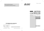
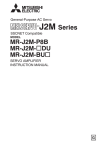
1.4 Structure
Front view
Mounting
hole
Side view
Mounting hole
21
0
CD RXST TXST
E D CB
8 7
CON8
6 5 43
OPEN
150 Ω
A9
150 Ω
1)Terminating
resistor
5)Station number
switch
F
OPEN
6)Earth(Ground)
terminal
3)Input
connector
5)Station number
switch
CON9
3)Input connector
FR-V5NS
4)Connector
3)Output connector
2)LED
Option fixing hole
Name
1) Terminating resistor
CD(carrier
disconnection alarm)
2) LED
RXST (receiving)
TXST (transmitting)
Communic
3) ation
connector
Input
Output
4) Connector
5) Station number switch
6) Earth (Ground) terminal
Function
Set terminating resistor present/absent using a jumper connector.
Refer
to
page
6
Lit when the inverter and host computer have been physically disconnected.
-
Lit while receiving.
Lit while transmitting.
Communication cable input connector for connecting SSCNET from the
motion controller or other FR-V500 series (servo amplifier).
Communication cable output connector for connecting SSCNET to other FRV500 series or the servo amplifier.
To be connected to the option unit connector of the inverter.
Set the station number of the inverter when connected to the motion controller.
To be connected to the ground terminal of the inverter.
2
-
5
12
PRE-OPERATION INSTRUCTIONS
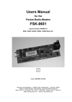
1.5 Operation Overview
In communication with the Mitsubishi motion controller, the inverter operation (speed control or position
control or torque control under vector control with encoder), monitoring, or parameter setting can be
performed from a program on the motion controller.
SSCNET enables less wiring, improved reliability, improved synchronous control performance and motion
controller-driven multi-axis batch control.
Motion controller
Motion control
FR-V500
FR-V5NS
Emergency stop
output shutoff
Torque command
Position command
Speed command
SSCNET
Torque command** interface
Control command
Emergency stop*
Monitor data
Speed command
SSCNET
interface Position
command
Position
Current
monitor
control
Speed
control
Torque
control**
Speed monitor/feedback pulse monitor
* When the emergency stop signal is input, the inverter shuts off the output and the motor coasts.
**Please contact your sales representative when performing torque control.
CAUTION
The inverter can perform vector control with encoder (speed control, position control, torque
control) under the command from the motion controller. (Pr. 800 "control system selection" is
made invalid.)
3
IM
Enco
der
2.INSTALLATION
2.1 Pre-Installation Instructions
Make sure that the input power of the inverter is off.
CAUTION
With input power on, do not install or remove the option unit. Otherwise, the inverter and
option unit may be damaged.
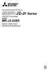
2.2 Setting the Station Numbers and Terminating Resistor
OUT
150Ω OPEN
IN
0
REMARKS
Refer to page 10 for the FR-V5NSCBL (SSCNET cable).
4
ED B
C
CB
ED
CB
98 7
ED
0
A
IN
150Ω OPEN
21
0
98 7
FR-V5NSCBL_
150Ω OPEN
A
FR-V5NSCBL_
F
Setting: 1 (second axis)
98 7
21
F
Setting: 0 (first axis)
FR-V5NS
65 3
4
21
65 3
4
65 3
4
Motion
controller
Q172CPU
FR-V5NS
A
FR-V5NS
F
Setting: 2 (third axis)
(Terminating resistor
FR-V5NSCBL_
present (150Ω))
150Ω OPEN
150Ω OPEN 150Ω OPEN
OUT
IN
OUT
INSTALLATION
2.2.1 Setting the station numbers
Set the inverter station number before switching on the inverter and do not change the setting while power is on.
SSCNET allows up to eight axes to be connected in one communication system.
Station number switch
Description
Station Number
Description
0
First axis
8
Not used.
98 7
1
2
3
4
5
6
Second axis
Third axis
Fourth axis
Fifth axis
Sixth axis
Seventh axis
9
A
B
C
D
E
7
Eighth axis
F
Not used.
Not used.
Not used.
Not used.
Not used.
Not used.
Normal start.
The inverter starts in the operation
mode set in Pr. 79 "operation mode
selection".
CB
ED
0
21
A
65 3
4
Station Number
Move the arrow ( ) to the position
corresponding to the station number you
want to set.
F
Factory setting
REMARKS
• If any of the station No. 8 to No. E is set to the inverter, it is placed in a communication initialization waiting status after
power-on, but communication is not established. Do not use 8 to E.
• When the station No. F is set to the inverter, it starts in the external operation mode (when Pr. 79 = 0) and operates
normally. It cannot perform SSCNET operation.
Refer to the inverter manual for Pr. 79 "operation mode selection" for the station No. F.
• Set the station numbers consecutively in connection order. (You can also set the station numbers independently of the
connection order.)
CAUTION
1.
2.
3.
If you change any station number while the inverter power is on, the setting is not made valid. The setting is
made valid after power is switched on again or the RES signal is turned on.
You cannot set the same station number to two or more inverters on the same bus. (Such setting disables
normal communication.)
Set the switch securely into the switch numeral position.
Setting it in a middle position disables normal data communication.
5
INSTALLATION
2.2.2 Setting the terminating resistor
The terminating resistor setting jumper connectors are factory-set in the terminating resistor absent
(OPEN) position. To make the terminating resistor present, change the positions of both jumper connectors
on the FR-V5NS to the 150Ω positions. Only the terminating resistor of the inverter (servo amplifier)
furthest from the motion controller should be made present (150Ω).
Factory setting
Factory setting
CAUTION
1. Do not change the jumper connector positions while power is on.
2. Jumper connectors must be fitted in either OPEN or 150Ω . If they are fitted in both positions at
the same time, the option unit may be damaged.
3. For the handling of the servo amplifier terminating resistor, refer to the instruction manual of
the servo amplifier.
6
INSTALLATION
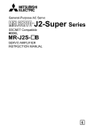
2.3 Installation and Removal
(1) Install the option unit to Slot 3. (If you install it to Slot 1 or 2, E.OP1 (E.OP2) is displayed and operation is not performed.)
(2) Insert the option unit connector into the Slot 3 connector of the inverter securely. At this time, also insert the option
fixing holes securely.
Refer to the following diagram for the position of Slot 3. Push the option unit securely into the option fixing hook.
(3) Fix the two right and left places of the option unit to the inverter securely with the accessory mounting screws. If
the screw holes do not line-up, the connector may not have been inserted securely. Check for insecure insertion.
Inverter
(Without cover)
Slot 1
Slot 2
Accessory screw (2 pcs.)
Inverter side connector
Slot 3
Option fixing hook
The option fixing hooks
are provided for Slots 1, 2, 3.
Option side connector (rear)
(4)
To remove the option unit, remove the two left and
right screws, and then hold the option unit and pull
its bottom toward you as shown in the figure. (The
option unit is fixed by the hook of the inverter.)
CAUTION
You cannot use this option with any other communication options. Also, there are restrictions on some of the other
option functions. (Refer to page 25.)
7
3. WIRING
3.1 Wiring Example
NFB
Power
supply
Motion
controller
Other FR-V500 +
FR-V5NS (or servo amplifier)
A Dedicated motor (SF-V5R)
(Note 1) B
FAN
C
FR-V500
R
U
S
V
W
U
V
W
E
OH
SD
G1
G2
PA
PAR
PB
PBR
PZ
PZR
PG
SD
A
B
C
D
F
G
S
R
N
T
SSCNET
unit
FR-V5NS
Earth
(Ground)
terminal
IM
Thermal
protector
Enco
der
Main circuit
terminals
Control circuit
terminals
Note 1: The fan power supply of the 7.5kW or
less dedicated motor is single-phase.
8
WIRING
3.2 Connection Example
Motion controller
Q172CPU
Power
supply
module
*
* Use enclosed ferrite cores to prevent noises from the
inverter from affecting SSCNET communication.
Wind the ferrite core around cables for both I/O sides
one time.
CAUTION
When the inverter installed on a cart, etc. is
affected by vibration, perform wiring in such a way
that the ferrite cores are secured.
PLC CPU
Motion CPU
2)
1)
Terminating resistor
*
*
Inverter
FR-V500 series + FR-V5NS
Motion controller
Q173CPU
Power
supply
module
Servo
MR-J2S-B
Inverter
FR-V500 series + FR-V5NS
Inverter
FR-V500 series + FR-V5NS
Servo
MR-H-BN
PLC CPU
Motion CPU
Cable branch unit
Q173DV
6)
4)
5)
Terminating resistor
3)
Motion controller CPU
Inverter
1), 5) FR-V5NSCBL_
Cables
2), 4)
6)
3)
*
*
*
*
Q173CPU or Q172CPU
FR-V500 series + FR-V5NS (SSCNET communication unit)
For connection of Q172CPU and FR-V5NS, for connection of FR-V5NS and FR-V5NS
For connection of Q172CPU/FR-V5NS and MR-J2-B/MR-J2S-B/MR-J2-03B5, for
Q172J2BCBL_M(-B)
connection of Q173DV and FR-V5NS
Q172HBCBL_M(-B) For connection of Q172CPU/FR-V5NS and MR-H-BN
Q173DVCBL_M
For connection of Q173CPU and Q173DV
9
WIRING
3.3 SSCNET Cables and Ground Cable
Use our optional SSCNET connection cables.
(1) Cable type
Type *
Q172J2BCBL_M(-B)
Q172HBCBL_M(-B)
FR-V5NSCBL_
Q173DVCBL_M
Length [m]
Cable Type
0.5, 1, 5
UL20276 AWG#28 7 pair (cream)
0.5, 1, 5, 10, 20
0.5, 1
UL20276 AWG#28 7 pair (ivory)
UL20276 AWG#28 13 pair (cream)
* _ in the type represents the cable length.
Symbol
Cable Length (m)
005
0.5
01
1
05
5
10
10
20
20
REMARKS
• If the necessary length is not found in the optional cables,
Connection
fabricate it on the customer side. For SSCNET cables, use
the twisted pair shielded cables indicated above or equivalent. diagram TXD1
TXD1*
The overall wiring length of the bus cables on the same bus is
SG
SG
30m.
RXD1
RXD1*
• When fabricating SSCNET cable on the user side
SG
• Connector: HDR-E14MGI x 2(Honda tsushin kogyo Co., Ltd)
BT
EMG1
• Wire: UL20276φ4.9 (Ivory AWG#28 x 7P)
EMG1*
(Bando electric wire co., Ltd.)
TXD2
1
8
2
9
3
10
6
13
4
11
5
TXD2* 12
RXD2 7
RXD2* 14
1
8
2
9
3
10
6
13
4
11
5
12
7
14
TXD1
TXD1*
SG
SG
RXD1
RXD1*
SG
BT
EMG1
EMG1*
TXD2
TXD2*
RXD2
RXD2*
CAUTION
• When fabricating a bus cable, make sure to connect cables to correct signals. Otherwise, overrun or burst may occur.
10
WIRING
(2) Earth (Ground) Cable
For wiring to the earth (ground) terminal of the FR-V5NS, use a crimping terminal with sleeve.
•Cable gause: 2 mm2
•Crimping terminal: 2-3.5 (with sleeve)
11
WIRING
3.4 Wiring Route
•Route the SSCNET cables using the space on the right side of the control circuit terminal.
•Connect the earth (ground) cable to the earth (ground) terminal of the inverter using the space on the left
side of the control circuit terminal. (For the position of the earth (ground) terminal of the inverter, refer to
the inverter manual.)
CAUTION
When reinstalling the front cover of the inverter, route the cables in the wiring space securely
so that the inverter control circuit terminal and option connection cables are not caught
between the inverter and cover.
12
4. SSCNET COMMUNICATION STATUS
When the inverter is fitted with the SSCNET communication unit (FR-V5NS) and has any of station No. 0 to No. 7, powering it on places it in the SSCNET communication initialization waiting status. In this status, the inverter is put in the
SSCNET operation mode and cannot be switched to the external or PU operation mode. In addition, the Pr. 79 "operation mode selection" setting is disabled. How SSCNET communication is performed is shown below.
The status of communication with the motion controller can be monitored as a communication status.
To monitor it, set "39" (communication status) in Pr. 52 "DU/PU main display data selection". (Refer to page 17.)
Inverter power-on
SSCNET communication status
(*1)
Waiting for initial communication
12
Motion controller
power-on
Initial communication start
13
Initial communication
parameter setting
14
Initial communication end
Inverter alarm
(outside initial
parameter range)
99
E.9
2#
(*2)
Alarm
code
(*3)
3#
(*2)
Emergency stop
88
Ready off/servo off
Alarm reset
Ready on/servo off
Ready on/servo on
Motion controller
power-off
Cancel
Communication shutoff
4#
(*2)
99
E.OP3
(*4)
CF alarm
(*5)
Waiting for initial communication
11
13
CommunicaDescription
tion Status
The V5NS is not fitted or the station number is F
0
After SSCNET communication had been estab11
lished, the motion controller powered off.
Immediately after the inverter has been powered
on, it is waiting for motion controller power-on
12
and initial communication.
Initialization communication start
13
The initial parameters are being received during
14
initialization.
Ready off was received.
2#
Servo off was received.
3#
Servo on was received.
4#
Emergency stop (inverter output shutoff)
88
Inverter trip
99
#: Axis number
*1. The inverter is put in the SSCNET operation mode.
*2. In the part #, the axis number appears.
("21" appears when the station number is 0.)
*3. To reset the alarm, the alarm reset signal from the SSCNET or the RES terminal is valid.
A power-on reset recovers the inverter from the alarm in
the initialization waiting status.
*4. When communication is interrupted, an inverter reset (CF
alarm) or inverter alarm (E.OP3) occurs.
To select alarm output presence/absence and stop operation, use Pr. 499 "action selection at SSCNET communication interruption". (Refer to page 17.)
*5. If the motion controller is powered off during inverter power
input, the inverter is placed in the initialization waiting status.
5. INITIAL COMMUNICATION SETTING FROM MOTION CONTROLLER
The following parameters are set during initial communication with the motion controller.
For the setting method, refer to the manual of the motion controller (Refer to page 1 for the manual types.)
No.
Basic
parameters
1
2
3
4
5
6
7
8
9
10
11
12
Adjustment
parameters
13
14
15
16
17
18
19
20
21
22
23
24
Name
Maximum speed
Electronic thermal O/L relay
Regenerative function selection
Special regenerative brake duty
Applied motor
Motor capacity
Number of motor poles
Online auto tuning selection
Torque restriction level
Torque restriction level (regeneration)
Torque restriction level
(3rd quadrant)
Torque restriction level
(4th quadrant)
Easy gain tuning response level setting
Easy gain tuning selection
Number of encoder pulses
Encoder rotation direction
Thermal protector input
Position loop gain
Position feed forward gain
In-position width
Error excessive level
Speed control P gain 1
Speed control integral time 1
Model speed control gain
Inverter
Parameter
No.
No.
Name
25 Notch filter frequency
26 Notch filter depth
Adjust- 27 Speed feed forward control/model adaptive speed control selection
ment
parame- 28 Speed feed forward filter
ters
29 Speed feed forward torque restriction
30 Load inertia ratio
31 Speed feed forward gain
32 DA1 terminal function selection
33 Speed monitoring reference
34 Current monitoring reference
Extended 35 DA2 terminal function selection
parame- 36 Overspeed detection level
ters
37 Torque characteristic selection
output region torque character38 Constant
istic selection
39 Torque monitoring reference
1
9
30
70
71
80
81
95
22
812
813
814
818
819
851
852
876
422
423
426
427
820
821
828
Inverter
Parameter
No.
862
863
877
878
879
880
881
54
55
56
158
374
801
803
866
CAUTION
If any of the initial communication setting parameter
values is outside the setting range, "E.9" is displayed at
the time of initial communication.
REMARKS
Refer to the inverter manual for details of the parameters.
14
6. INVERTER SETTINGS AND INDICATIONS
6.1 Operation Mode Switchover
Power-on
1)
SSCNET
operation
2) (When Pr. 79 = 0 (factory setting))
C
D
External
operation
A
B
PU
operation
E
F
(1) Starting operation mode
Symbol
Switchover Type
1)
SSCNET operation mode
2)
External operation (Pr. 79 = 0 (factory setting))
Switchover Method
When the station number setting is any of 0 to 7 (first to eighth axes).
(SSCNET operation is enabled at completion of initial communication.)
When the FR-V5NS is not fitted or the station number setting is F.
(2) Operation mode switchover (When Pr. 79 = 0)
Symbol
Switchover Type
Switchover Method
D
External operation →
PU operation
PU operation →
external operation
SSCNET operation →
external operation
External operation →
SSCNET operation
Switchover is disabled while power is on. After switching power off, remove the FR-V5NS or set the station number to F and switch power on.
Switchover is disabled while power is on. After switching power off, set the station number to any of 0 to
7 and switch power on with the FR-V5NS fitted.
E
SSCNET operation →
PU operation
Switchover is disabled while power is on. After switching power off, remove the FR-V5NS or set the station number to F, switch power on, and then press the PU button to switch the operation mode.
F
PU operation →
SSCNET operation
Switchover is disabled while power is on. After switching power off, set the station number to any of 0 to 7
and switch power on with the FR-V5NS fitted.
A
B
C
Operate the PU operation key on the PU.
Operate the external operation key on the PU.
15
INVERTER SETTINGS AND INDICATIONS
CAUTION
1. In the SSCNET operation mode, the Pr. 79 "operation mode selection" setting is invalid.
2. Any station number changed with power on is invalid. The setting is made valid when power is
switched on again or a reset is made with the RES terminal.
STOP
3. Even if SSCNET operation is being performed,
of the PU (FR-DU04-1/FR-PU04V) can
RESET
be used to make a stop (when Pr. 75 = 14 (factory setting) to 17). At this time, the deceleration
time is 0s. Refer to the inverter manual for Pr. 75 "PU stop selection".
REMARKS
During SSCNET operation, "NET" is displayed on the FR-PU04V and the "EXT" LED is lit on the FR-DU04-1 to indicate the operation mode.
6.2 Initial Communication Waiting Status ("CF" alarm)
If SSCNET communication is disabled due to the fault of the communication cable and the power-off of the
communication equipment (personal computer) or motion controller, etc., the output is shut off and the CF
alarm is displayed on the FR-DU04-1 (or FR-PU04V).
Pr. 499 "action selection at SSCNET communication interruption" can be used to select the operation to be
performed at occurrence of communication interruption.
16
INVERTER SETTINGS AND INDICATIONS
6.2.1 Pr. 499 "action selection at SSCNET communication interruption"
You can select the operation to be performed at occurrence of communication interruption.
Pr. 499 Setting
Operation
0
(Factory setting)
Output shutoff
(coasting)
1
Output shutoff
(coasting)
Reset the inverter.
The inverter is placed in the initial communication waiting status (CF
alarm) and can be recovered from the alarm when initial communication is restarted.
"E.OP3" is displayed.
Resetting the inverter places it in the initial communication waiting status (CF alarm) and allows it to be recovered from the alarm when initial
communication is restarted.
REMARKS
If communication data is in a CRC error etc., E.OP3 occurs regardless of the Pr. 499 setting.
6.2.2 Pr. 52 "DU/PU main display data selection"
You can select the SSCNET communication status to be displayed on the operation panel or parameter
unit. To display it, set "39" in Pr. 52 and select the voltage monitor (third monitor). Refer to page 13 for the
monitored data.
Pr.No
52
Function
Setting Range
Remarks
Set
39
to
display
the SSCNET
DU/PU main display data selection 0, 5 to 12, 17 to 20, 23, 24, 32 to 35, 38, 39 communication status
monitor.
REMARKS
For the set values of other than "39", refer to the inverter manual.
17
7. RESTRICTIONS ON THE FUNCTIONS
7.1 Inverter Parameter List
Function validity: There are restrictions on the inverter functions in the SSCNET communication operation
mode. O indicates the valid parameter, and X the invalid parameter.
Inverter
Parameter No.
Name
Name
Function
Validity
Acceleration/deceleration time
increments
X
44
Second acceleration/deceleration
time
X
22
Torque restriction level
O
45
Second deceleration time
X
24
Multi-speed setting (speed 4)
X
50
Second speed detection
O
25
Multi-speed setting (speed 5)
X
26
Multi-speed setting (speed 6)
X
52
DU/PU main display data
selection
O
PU level display data selection
O
21
Torque boost (manual)
X
1
Maximum speed
O
Minimum speed
Inverter
Parameter No.
Inverter
Parameter No.
0
2
Function
Validity
Function
Validity
X
3
Base frequency
X
4
Multi-speed setting (high speed)
X
5
Multi-speed setting (middle
speed)
Name
X
27
Multi-speed setting (speed 7)
X
53
Multi-speed input compensation
X
54
DA1 terminal function selection
O
Acceleration/deceleration pattern
X
55
Speed monitoring reference
O
Current monitoring reference
O
6
Multi-speed setting (low speed)
X
28
7
Acceleration time
X
29
8
Deceleration time
X
30
Regenerative function selection
O
56
O
31
Speed jump 1A
X
57
Restart coasting time
X
32
Speed jump 1B
X
58
Restart cushion time
X
Remote setting function selection
X
9
Electronic thermal O/L relay
10
DC injection brake operation
speed
X
33
Speed jump 2A
X
59
11
DC injection brake operation time
X
34
Speed jump 2B
X
60
Intelligent mode selection
X
12
DC injection brake voltage
X
35
Speed jump 3A
X
65
Retry selection
X
13
Starting speed
X
36
Speed jump 3B
X
67
X
15
Jog speed setting
X
37
Speed display
O
Number of retries at alarm
occurrence
Up-to-speed sensitivity
X
X
X
41
Retry waiting time
16
Jog acceleration/deceleration
time
68
O
O
X
MRS input selection
Speed detection
Retry count display erasure
17
42
69
Special regenerative brake duty
O
19
Base frequency voltage
X
43
Speed detection for reverse
rotation
70
O
71
Applied motor
O
20
Acceleration/deceleration
reference speed
72
PWM frequency selection
O
X
18
RESTRICTIONS ON THE FUNCTIONS
Inverter
Parameter No.
Name
Function
Validity
Inverter
Parameter No.
Name
Function
Validity
Inverter
Parameter No.
73
Speed setting signal
X
75
Reset selection/disconnected PU
detection/PU stop selection
O
77
Parameter write disable selection
O
78
Reverse rotation prevention
selection
O
79
Operation mode selection
X
80
Motor capacity
O
81
Number of motor poles
O
82
Motor excitation current (no load
current)
O
83
Rated motor voltage
84
Rated motor frequency
90
Motor constant R1
O
91
Motor constant R2
O
92
Motor constant L1
O
93
Motor constant L2
O
94
Motor constant X
O
95
Online auto tuning selection
O
96
Auto tuning setting/status
O
110
Third acceleration/deceleration
time
X
111
Third deceleration time
X
143
Backlash deceleration stopping
time
X
116
Third speed detection
O
144
Speed setting switchover
117
Station number
O
145
118
Communication speed
O
150
Name
Function
Validity
119
Stop bit length/data length
O
151
Output current detection time
O
120
Parity check presence/absence
O
152
Zero current detection level
O
121
Number of communication retries
O
153
Zero current detection time
O
122
Communication check time
interval
O
156
Stall prevention operation
selection
O
123
Waiting time setting
O
157
OL signal output timer
O
124
CR, LF presence/absence
selection
O
158
DA2 terminal function selection
O
160
Extended function selection
O
128
PID action selection
X
129
PID proportional band
X
162
X
130
PID integral time
X
Automatic restart after
instantaneous power failure
selection
O
131
Upper limit
X
163
First cushion time for restart
X
O
132
Lower limit
X
164
First cushion voltage for restart
X
165
Restart current restriction level
X
171
Actual operation hour meter clear
O
133
PID action set point for PU
operation
X
134
PID differential time
X
140
Backlash acceleration stopping
speed
X
141
Backlash acceleration stopping
time
X
Backlash deceleration stopping
speed
X
142
180* DI1 terminal function selection
O
181* DI2 terminal function selection
O
182* DI3 terminal function selection
O
183* DI4 terminal function selection
O
187* STR terminal function selection
O
190* DO1 terminal function selection
O
191* DO2 terminal function selection
O
192* DO3 terminal function selection
O
X
195* A,B,C terminal function selection
O
PU display language selection
O
232
Multi-speed setting (speed 8)
X
Output current detection level
O
233
Multi-speed setting (speed 9)
X
*Some functions of the I/O signals set using these parameters are invalid. Refer to page 24.
19
RESTRICTIONS ON THE FUNCTIONS
Inverter
Parameter No.
Name
Function
Validity
Inverter
Parameter No.
Name
Function
Validity
Inverter
Parameter No.
Name
Function
Validity
234
Multi-speed setting (speed 10)
X
281
Brake operation time at start
X
318
Y5 output selection
O
235
Multi-speed setting (speed 11)
X
282
Brake operation speed
X
319
Y6 output selection
O
236
Multi-speed setting (speed 12)
X
283
Brake operation time at stop
X
320
RA1 output selection
O
237
Multi-speed setting (speed 13)
X
O
X
X
RA2 output selection
Multi-speed setting (speed 14)
284
321
238
Deceleration detection function
selection
322
RA3 output selection
O
239
Multi-speed setting (speed 15)
X
285
Overspeed detection speed
X
330
RA output selection
O
240
Soft-PWM setting
O
286
Droop gain
O
331
Station number
X
244
Cooling fan operation selection
O
287
Droop filter constant
O
332
Communication speed
X
250
Stop selection
X
288
O
333
Stop bit length
X
251
Output phase failure protection
selection
Droop function activation
selection
O
306
Analog output signal selection
O
334
Parity check presence/absence
X
X
O
X
Override bias
Setting for zero analog output
Number of communication retries
252
307
335
253
Override gain
X
308
O
336
X
261
Power failure stop selection
X
Setting for maximum analog
output
Communication check time
interval
Waiting time setting
X
262
Subtracted speed at deceleration
start
X
309
Analog output signal voltage/current
switchover
337
O
341
X
263
Subtraction starting speed
X
310
Analog meter voltage output
selection
CR/LF presence/absence
selection
O
342
E2PROM
write selection
O
264
Power-failure deceleration time 1
X
X
X
O
Stop position command selection
Power-failure deceleration time 2
311
350
265
Setting for zero analog meter
voltage output
351
Orientation switchover speed
X
266
Power-failure deceleration time
switchover speed
X
312
Setting for maximum analog
meter voltage output
O
356
Internal stop position command
X
278
Brake opening speed
X
313
Y0 output selection
In-position zone
X
O
357
279
Brake opening current
X
314
Y1 output selection
O
360
External position command
selection
X
280
Brake opening current detection
time
315
Y2 output selection
O
361
Position shift
X
316
Y3 output selection
O
362
Orientation position loop gain
X
317
Y4 output selection
O
X
*Some functions of the I/O signals set using these parameters are invalid. Refer to page 24.
20
RESTRICTIONS ON THE FUNCTIONS
Inverter
Parameter No.
Name
Function
Validity
374
Overspeed detection level
O
380
Acceleration S pattern 1
X
Inverter
Parameter No.
Name
Function
Validity
Inverter
Parameter No.
Name
Function
Validity
469
Third position feed amount lower
4 digits
X
470
Third position feed amount upper
4 digits
X
421
Command pulse scaling factor
denominator
X
Position loop gain
O
381
Deceleration S pattern 1
X
422
382
Acceleration S pattern 2
X
423
Position feed forward gain
O
383
Deceleration S pattern 2
X
424
X
471
Fourth position feed amount
lower 4 digits
X
393
Orientation selection
X
Position command acceleration/
deceleration time constant
396
Orientation speed gain (P term)
X
425
Position feed forward command
filter
X
472
Fourth position feed amount
upper 4 digits
X
397
Orientation speed integral time
X
426
In-position width
O
398
Orientation speed gain (D term)
X
473
X
427
Excessive level error
O
Fifth position feed amount lower
4 digits
399
Orientation deceleration ratio
474
Fifth position feed amount upper
4 digits
X
475
Sixth position feed amount lower
4 digits
X
476
Sixth position feed amount upper
4 digits
X
477
Seventh position feed amount
lower 4 digits
X
478
Seventh position feed amount
upper 4 digits
X
479
Eighth position feed amount
lower 4 digits
X
480
Eighth position feed amount
upper 4 digits
X
481
Ninth position feed amount lower
4 digits
X
482
Ninth position feed amount upper
4 digits
X
X
430
Pulse monitor selection
O
400* DI11 terminal function selection
O
450
Second applied motor
X
401* DI12 terminal function selection
O
402* DI13 terminal function selection
O
451
Second motor control method
selection
X
403* DI14 terminal function selection
O
404* DI15 terminal function selection
O
452
Second electronic thermal O/L
relay
X
405* DI16 terminal function selection
O
453
Second motor capacity
X
454
Number of second motor poles
X
464
Digital position control suddenstop deceleration time
X
465
First position feed amount lower
4 digits
X
466
First position feed amount upper
4 digits
X
406
407
High resolution analog input
selection
X
Motor temperature detection filter
O
410* D011 terminal function selection
O
411* D012 terminal function selection
O
412* D013 terminal function selection
O
413
Encoder pulse output division ratio
O
419
Position command right selection
X
467
Second position feed amount
lower 4 digits
X
420
Command pulse scaling factor
numerator
X
468
Second position feed amount
upper 4 digits
X
21
RESTRICTIONS ON THE FUNCTIONS
Inverter
Parameter No.
Name
Function
Validity
483
Tenth position feed amount lower
4 digits
X
484
Tenth position feed amount upper
4 digits
X
Eleventh position feed amount
lower 4 digits
X
485
Inverter
Parameter No.
Name
Function
Validity
Inverter
Parameter No.
Control system selection
X
820
Speed control P gain 1
O
801
Torque characteristic selection
O
821
Speed control integral time 1
O
802
Pre-excitation selection
O
822
Speed setting filter 1
X
803
Constant output region torque
characteristic selection
O
823
Speed detection filter 1
O
824
Torque control P gain 1
O
804
Torque command right selection
X
825
Torque control integral time 1
O
805
Torque command value (RAM)
X
826
Torque setting filter 1
X
806
Torque command value (RAM,
E2PROM)
X
827
Torque detection filter 1
O
Speed restriction selection
828
Model speed control gain
O
807
X
Forward rotation speed restriction
Speed control P gain 2
X
808
830
X
Speed control integral time 2
X
809
Reverse rotation speed
restriction
831
X
832
Speed setting filter 2
X
833
Speed detection filter 2
X
810
Torque restriction input method
selection
X
834
Torque control P gain 2
X
812
Torque restriction level
(regeneration)
835
Torque control integral time 2
X
836
Torque setting filter 2
X
813
Torque restriction level
(3 quadrant)
O
837
Torque detection filter 2
X
840
Torque bias selection
X
814
Torque restriction level
(4 quadrant)
O
841
Torque bias 1
X
815
Torque restriction level 2
X
842
Torque bias 2
X
816
Acceleration torque restriction
X
843
Torque bias 3
X
817
Deceleration torque restriction
X
844
Torque bias filter
X
845
Torque bias operation time
X
846
Torque bias balance
compensation
X
Eleventh position feed amount
upper 4 digits
487
Twelfth position feed amount
lower 4 digits
X
488
Twelfth position feed amount
upper 4 digits
X
489
Thirteenth position feed amount
lower 4 digits
X
490
Thirteenth position feed amount
upper 4 digits
491
Fourteenth position feed amount
lower 4 digits
X
492
Fourteenth position feed amount
upper 4 digits
X
Fifteenth position feed amount
lower 4 digits
X
494
Fifteenth position feed amount
upper 4 digits
X
495
Remote output selection
O
496
Remote output data 1
O
497
Remote output data 2
O
818
Easy gain tuning response level
setting
O
499
Action selection at SSCNET
communication interruption
O
819
Easy gain tuning selection
O
493
X
Function
Validity
800
486
X
Name
22
O
RESTRICTIONS ON THE FUNCTIONS
Inverter
Parameter No.
Name
Function
Validity
Inverter
Parameter No.
X
879
Speed feed forward torque
restriction
O
880
Load inertia ratio
O
881
Speed feed forward gain
O
Name
Function
Validity
847
Fall-time torque bias
No. 3 bias
848
Fall-time torque bias
No. 3 gain
X
849
Analog input offset adjustment
X
890
Maintenance output setting time
O
851
Number of PLG pulses
O
891
Maintenance output timer
O
852
PLG rotation direction
O
892
Maintenance output signal clear
O
854
Excitation ratio
O
900
DA1 terminal calibration
O
859
Torque current
O
901
DA2 terminal calibration
O
862
Notch filter frequency
O
902
Speed setting No.2 bias
X
863
Notch filter depth
O
903
Speed setting No.2 gain
X
864
Torque detection
O
904
Torque command No.3 bias
X
865
Low speed detection
O
905
Torque command No.3 gain
X
866
Torque monitoring reference
O
917
No. 1 terminal bias (speed)
X
867
DA1 output filter
O
918
No. 1 terminal gain (speed)
X
868
No. 1 terminal function
assignment
X
919
No. 1 terminal bias (torque/
magnetic flux)
X
870
Speed deviation level
O
871
Speed deviation time
O
920
No. 1 terminal gain (torque/
magnetic flux)
X
873
Speed restriction
X
990
PU buzzer control
O
874
OLT level setting
O
991
PU contrast adjustment
O
875
Fault definition
X
876
Thermal protector input
O
877
Speed feed forward/model
adaptive speed control selection
O
878
Speed feed forward filter
O
23
RESTRICTIONS ON THE FUNCTIONS
REMARKS
Whether the I/O terminal function in the SSCNET communication operation mode is valid or invalid is indicated by O or X.
Input Signal
Signal name
RL
RM
RH
Low-speed operation command
(Pr. 59 = 0)
X
Remote setting (setting clear)
(Pr. 59 = other than 0)
X
Mid-speed operation command
(Pr. 59 = 0)
X
Remote setting (deceleration)
(Pr. 59 = other than 0)
X
X
Remote setting (acceleration)
(Pr. 59 = other than 0)
X
RT
Second function selection/
second motor switchover
X
JOG
Jog operation selection
X
X
X9
Third function selection
X
X10
FR-HC, FR-CV connection
(Inverter operation enable
signal)
O
X11
X12
FR-HC connection
(instantaneous power failure
detection)
PU operation external interlock
signal
Validity
Signal name
X14
PID control enable terminal
X
BRI Brake sequence opening signal X
High-speed operation command
(Pr. 59 = 0)
15 speed selection
REX (Combination with three speeds RL,
RM, RH)
Output Signal
Input Signal
Validity
X
X
Signal name
Output Signal
Validity
RUN
Inverter running
O
SU
Up to speed
X
IPF
Instantaneous power
failure or undervoltage
O
OL
Overload alarm
O
X16
PU operation/external operation
switchover
X20
S-pattern acceleration/
deceleration C switchover
terminal
X
FU,
FB
Output speed detection
O
X22
Orientation command
X
LX
Pre-excitation/servo on
X
FU2,
FB2
Second output speed
detection
O
MRS
Output stop
O
FU3,
FB3
Third output speed
detection
O
RBP
Regenerative brake
prealarm
O
X
STOP
Start self-hold selection
X
MC
Control mode switchover
X
TL
Torque restriction selection
X
X42
Torque bias selection 1
X
X43
Torque bias selection 2
X
X44
P control selection
(P/PI control switchover)
X
X45
Servo on (position control)
X
STR
Reverse rotation command
STF
Forward rotation command
OH
External thermal relay
O
-
No function
O
RES
Reset
O
1
Speed setting auxiliary input
X
2
Speed setting input
X
Validity
FAN
Fan fault output
O
O
FIN
Heatsink overheat
prealarm
ORA
Orientation in-position
X
Y30
Output during forward
rotation
O
Y31
Output during reverse
rotation
O
Y32
Regeneration status
output
O
RY2
Operation ready 2
O
O
LS
Low speed output
TU
Torque detection
O
Y36
In-position
O
THP
Electronic thermal
overload protection
prealarm
O
MT Maintenance timer output
O
PU
PU operation mode
X
Y40
Trace status
O
RY
RUN
2
Inverter running 2
O
REM
Remote output*
O
ER
Minor fault output 2
X
LF
Minor fault output
O
ABC
Alarm output
O
-
No function
O
Inverter operation ready
O
Y12 Output current detection
O
X
Y13
Zero current detection
O
X
FDN
PID lower limit
X
FUP
PID upper limit
X
RL
PID forward/reverse
rotation output
X
BOF
Brake opening request
X
24
Signal name
* The function using the PU
connector is valid.
8. PRECAUTIONS
• The inverter parameter values cannot be changed from the motion controller. Use the PU (FR-DU04-1/
FR-PU04V) to change them. (Except the initial communication setting parameters)
• The usable encoder pulses are 1000 to 4096 pulses.
• Start and stop are SSCNET commands, and STR and STF are disabled. Among the external inputs (commands), only MRS, RES and OH are enabled.
• Before starting operation, always give the servo ON signal from the host controller to put the motor in the
servo lock status, and then start operation.
• The running speed and rotation direction are as commanded from the motion controller.
• During SSCNET operation, the acceleration/deceleration of the inverter is automatically set to 0 s.
When "0" is set in Pr.288 "droop function activation selection", droop control can not be performed. Set
"1" or "2" in Pr.288. (For details, refer to the inverter manual.)
• The overcurrent and overvoltage alarms in the SSCNET operation mode are "E.OC3" and "E.OV3", respectively. (For details, refer to the inverter manual.)
• The restrictions on the I/O signals (refer to page 24) also apply to the case where any of the other options
(FR-A5AY, FR-A5AR, FR-A5NR, FR-V5AX, FR-V5AY) is used with this option. (When the FR-A5NR is
used with this option, RS-485 communication is disabled.)
• Offline auto tuning cannot be performed from the motion controller. Perform it from the PU before starting
communication.
25
9. ALARM INDICATION DEFINITIONS AND CORRECTIVE ACTIONS
This section provides the definitions of the alarm indications and their corrective actions.
(1) Faults
When any of the protective functions is activated, the inverter shuts off the output and outputs the corresponding alarm.
When the protective function is activated, find the cause, and then refer to the inverter manual and reset
the inverter to resume operation.
Operation panel
indication
Name
Description
Check point
Corrective action
Operation panel
indication
Name
Description
Check point
Corrective action
E.OP3
FR-PU04V
Option slot alarm 3
Option slot 3 alarm
• If communication shutoff occurs at the Pr. 499 "action selection at SSCNET communication interruption"
setting of "1", this alarm is displayed and the inverter output is stopped. If a communication line alarm
occurs between the motion controller and plug-in option, the inverter output is stopped.
• Check for communication shutoff.
• Check that the plug-in option is connected to the connector securely.
• Check the communication cable for wire break.
• Check that the terminating resistor is set correctly.
• Check that the option card is normal.
• Recover communication from shutoff.
• Check the option function settings, etc.
• Connect the plug-in option securely.
E. 3
FR-PU04V
Fault 3
Option alarm
If poor contact etc. occurs at the connector between the inverter and communication option, the inverter output is stopped.
Check that the communication option is plugged into the connector securely.
• Connect the communication option securely.
• Contact your sales representative.
26
ALARM INDICATION DEFINITIONS AND CORRECTIVE ACTIONS
Operation panel
indication
Name
Description
Check point
Corrective action
E. 9
FR-PU04V
Fault 9
Initial communication alarm
If any of the values set in the initial communication parameters is outside the setting range at the time of initial communication of the motion controller and inverter (FR-V5NS), the alarm is displayed and initial communication is stopped.
Check that the initial communication parameter values are set within the setting ranges.
Refer to page 14 and check the initial communication parameter values.
(2) Alarm
When the protective function is activated, the output is not shut off.
Operation panel
indication
Name
Description
Check point
Corrective action
CF
FR-PU04V
CF
Initial communication waiting status
If SSCNET communication is disabled due to the fault of the communication cable or the power-off of the
communication equipment (personal computer) or motion controller, the output is shut off and the alarm is
displayed.
The operation to be performed at occurrence of communication shutoff can be selected using Pr. 499 "action
selection at SSCNET communication interruption".
• Check the communication cable for a fault.
• Check that the communication equipment (personal computer) and motion controller have not been powered off.
• Check that the setting of Pr. 499 "action selection at SSCNET communication interruption" is correct.
• Change the communication cable.
• Power on the communication equipment (personal computer) and motion controller.
• Check the Pr. 499 "action selection at SSCNET communication interruption" setting.
27
REVISIONS
*The manual number is given on the bottom left of the back cover.
Print Date
*Manual Number
May, 2002
Jul., 2003
IB(NA)-0600106E-A
IB(NA)-0600106E-B
Feb., 2005
IB(NA)-0600106E-C
Revision
First edition
Additions
Torque control setting
Additions
Procedure for fabricating SSCNET cable