1
PowerNet
™
Twin Client
Terminal Emulation for Falcon RF ™
User’s Guide
PowerNet Twin Client User’s Guide
Second Edition ©2000
All rights reserved. No part of this work may be reproduced,
transmitted, or stored in any form or by any means without prior
written consent, except by a reviewer, who may quote brief
passages in a review, or as provided for in the Copyright Act of
1976.
Datalight Sockets® are a registered trademark of Datalight.
Novell® is a registered trademark of Novell.
PSC® is a registered trademark of PSC Inc.
Falcon™ is a trademark of PSC Inc.
PowerNet Twin Client™ is a trademark of Connect, Inc.
Windows® is a registered trademark of Microsoft Corporation.
Many of the designations used by manufacturers and sellers to distinguish their products are
claimed as trademarks. Where these designations appear here and
When the authors were aware of a trademark or registered trademark claim, the designations
have been printed with a trademark or registered trademark (™ or ®) symbol.
The information contained in this document is subject to change without notice.
00-649-00
3/2000
CONTENTS
Introduction: PowerNet Twin Client Emulator .......................... v
What is PowerNet Twin Client......................................................... vii
Chapter 1: Getting Started ........................................................ 1-1
Installation ............................................................................................ 1-3
Loading Default PowerNet Twin Client on Falcon ................. 1-4
Starting PowerNet Twin Client....................................................... 1-6
Configure PowerNet Twin Client................................................... 1-7
Configuration Menu .............................................................. 1-7
Edit IP .......................................................................................... 1-8
Edit Host List............................................................................. 1-9
Edit Authorization.................................................................1-10
PowerNet Twin Client Demo Mode ...............................1-11
Running Emulator ........................................................................... 1-12
Viewport Panning ........................................................................... 1-13
Chapter 2: Configuration Utility.............................................. 2-1
Starting Configuration Utility.......................................................... 2-3
Set Emulation and Servers .............................................................. 2-4
Emulation .................................................................................. 2-4
Host Servers.............................................................................. 2-4
New-Environ Setting .............................................................. 2-6
Configuring PowerNet Twin Client............................................... 2-7
The Keyboard Tab ................................................................. 2-8
The Display Tab....................................................................2-11
The Scanner Tab...................................................................2-19
The Log Levels Tab..............................................................2-22
The Polling/Timers Tab......................................................2-23
The Alarm Tab.......................................................................2-27
The Printer Tab .....................................................................2-30
The Misc Tab..........................................................................2-32
Load New Configuration .............................................................. 2-34
PowerNet Twin Client User Guide
<i>
Chapter 3: Advanced Keyboard Options............................. 3-1
Keyboard Macros ............................................................................... 3-3
Falcon Key Codes ................................................................... 3-3
Build Keyboard Macro Object File .................................... 3-3
Keyboard Mapping ............................................................................ 3-5
Define Keyboard Mapping Object.................................... 3-7
Chapter 4: Advanced Display Options.................................. 4-1
Display Mapping Object................................................................... 4-3
Character Sets .......................................................................... 4-3
Build Display Mapping Object File.................................... 4-4
Chapter 5: Advanced Scanner Options ................................ 5-1
Data Mapping Object........................................................................ 5-3
Build Data Mapping Object File......................................... 5-3
Data Editor Object.............................................................................. 7-5
Build Data Editor Object File............................................... 5-7
Decoder Control Object.................................................................... 5-8
Chapter 6: Extended Commands ........................................... 6-1
Barcode Decoder Control ................................................................ 6-3
Input Mode ........................................................................................... 6-4
Input Validation .................................................................................. 6-5
Double High/Wide............................................................................. 6-6
Beeper Control .................................................................................... 6-7
Video Attributes .................................................................................. 6-8
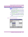
Chapter 7: Screen Capture Utility........................................... 7-1
Start Screen Capture .......................................................................... 7-3
Identify Terminal Host...................................................................... 7-4
Capture Screens .................................................................................. 7-6
< ii >
PowerNet Twin Client User Guide
Chapter 8: Screen Formatter Utility ...................................... 8-1
Starting the Screen Formatter ........................................................ 8-3
Configure Screen Formatter................................................ 8-3
Screen Formatting Concepts........................................................... 8-4
Screen Elements...................................................................... 8-5
Screen Formatter Environment.......................................... 8-6
Using PowerNet Twin Client Screen Formatter........................ 8-7
Specify Screen Identifier ....................................................... 8-8
Mark Screen Elements .......................................................... 8-9
Build Terminal Screen.........................................................8-12
After Reformatting ...............................................................8-15
Appendix A: Keyboard Maps for the PSC Falcon 315..........................A-i
Model VT.............................................................................................. A-iii
Models 3270/5250 .......................................................................... A-iv
Appendix B: Keyboard Maps for the PSC Falcon 325..........................B-i
Model VT.............................................................................................. B-iii
Models 3270/5250 ........................................................................... B-v
Appendix C: Keyboard Maps for the PSC Falcon 335..........................C-i
Model VT.............................................................................................. C-iii
Models 3270/5250 ........................................................................... B-v
Appendix D: Keyboard Maps for the LXE ................................................ D-i
Model VT.............................................................................................. D-iii
Models 3270/5250 ...........................................................................D-v
Index: PowerNet Twin Client .................................. Index-i
PowerNet Twin Client User Guide
< iii >
INTRO
PowerNet Twin
Client Emulator
What is PowerNet Twin Client
PowerNet Twin Client is a terminal emulation and screen formatting
package. This application supports VT100/220, HP700/92, and IBM
3270/5250 emulation.
PowerNet Twin Client consists of a telnet client that will run on a standalone terminal client and a Windows-based configuration. The formatting utility provides screen shaping without the need for an NCU (Network Control Utility).
PowerNet TN and PowerNet Twin Client refer to the same application
and are used interchangeably in this document.
PowerNet Twin Client: Basic Features
The following basic features are available with PowerNet Twin Client
configurations:
• Industry standard telnet protocol over TCP/IP.
• Windows-based configuration utility.
• Extended command set for terminal control from
the host application.
PowerNet Twin Client: Advanced Features
The PowerNet Twin Client also has advanced features that improve the
ability to reformat host application screens:
I The Screen Capture Utility is a Windows-based terminal
emulator. This utility captures "snapshots" of the host
application screens that are formatted by the Screen Formatter
Utility.
I The Screen Formatter Utility builds screen formatter files for
use on the terminal. A Windows interface is used to capture
the 80 column by 24 row terminal screens and then reformat
them to fit into the terminal’s screen area.
PowerNet Twin Client User Guide
< vii >
1
Getting Started
CHAPTER CONTENTS
Installation........................................................ <1-3>
Loading Default PowerNet Twin Client
on Falcon .................................................... <1-4>
Starting PowerNet Twin Client .........................<1-6>
Configure PowerNet Twin Client ......................<1-7>
Configuration Menu
Edit IP
Edit Host List
Edit Authorization
PowerNet Twin ClientDemo Mode
Running Emulator ............................................ <1-12>
Viewport Panning ............................................. <1-13>
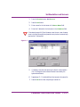
Installation
Installation
To install PowerNet Twin Client, insert the CD into the CD drive.
Complete the following steps:
1.
Open the CD drive directory. Run the setup.exe file.
2.
Read the on-screen instructions and press the Next button to
continue the installation.
3.
Press the Next button to accept the default installation directory.
The default directory is C:\PWRNETTN.
w If necessary, press the Browse button to define a different
installation directory.
w Press the Next button to continue the installation process.
4.
Press the Next button to accept the default Program Folder for the
PowerNet TN startup icon. The default program folder is
PowerNetTN.
w If necessary, enter an alternate program folder name in the
Program Folders field at the top of the Select Program
Folder form.
w Press the Next button to continue the installation process.
5.
Enter PE3892 as the installation key in the blank dialog box.
Press the Next button.
6.
Press the OK button when the “Installation Complete” message
appears.
PowerNet Twin Client User Guide
< 1-3 >
Getting Started
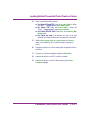
Loading Default PowerNet Twin Client on Falcon
The next task is to load a basic PowerNet Twin Client configuration
onto the Falcon.
Complete the following steps:
For Falcon 6x5 only: Begin with step 2.
1.
Type FORMAT at the C:\ prompt on the Falcon. Press ENTER
to begin formatting.
2.
Use the serial cable provided with the Falcon to connect the
Falcon’s serial port to a serial port on the PC.
3.
Press the Windows Start button.
4.
Select Programs and then select PowerNet TN.
5.
Select Configuration Utility to start the PowerNet Twin Client
Windows configuration utility.
6.
Open the Terminal menu and select Options.
7.
Select the Falcon Type from the Terminal Model list.
8.
Select the type of radio installed in the Falcon from the Radio
Type list.
9.
< 1-4 >
From the Communications Port group, select the COM Port that
will be used by the PC to communicate with the Falcon.
w The selected COM Port must match the port the serial cable
was attached to in Step 2.
10.
Press the OK button to save the selected options.
11.
Select Save As from the File menu.
12.
Enter default.cf in the File Name field and press the Save
button.
13.
Verify that the Falcon is turned on and at a C:\ prompt.
PowerNet Twin Client User Guide
Loading Default PowerNet Twin Client on Falcon
14.
Perform a safe-boot of the terminal.
w For Falcon 315 and 325: Press <CTL><ALT><DEL>. When
the “Wait...” message appears, press <ESC><DEL>.
w For Falcon 335: Press <CTL><ALT><DEL>. When the
“Wait...” message appears, press <ESC><SPACE>.
w For Falcon 615/655 (6x5): Press <F5> at the starting MSDOS prompt.
w For Falcon 3xx only: The terminal will emit a low tone
followed by a higher pitched tone if the safe-boot is successful.
15.
Select Send Program Files to Terminal from the Terminal
menu in the PowerNet Twin Client Windows Configuration
utility.
16.
Press the Yes button to confirm sending the configuration files to
the Falcon.
17.
Type LD on the Falcon keypad and press the ENTER key.
18.
Press the OK button on the PC to start the transfer.
19.
Press the OK button on the PC after receiving the Transfer
Complete message.
PowerNet Twin Client User Guide
< 1-5 >
Getting Started
Starting PowerNet Twin Client
To complete the installation process, perform a safe reboot the Falcon
terminal:
w For Falcon 315 and 325: Press <CTL><ALT><DEL>. When
the “Wait...” message appears, press <ESC><DEL>.
w For Falcon 335: Press <CTL><ALT><DEL>. When the
“Wait...” message appears, press <ESC><SPACE>.
w For Falcon 615/655 (6x5): Press <F5> at the starting MSDOS prompt.
w For Falcon 3xx only: The terminal will emit a low tone
followed by a higher pitched tone if the safe-boot is successful.
After rebooting the Falcon, the PowerNet Twin Client will start
automatically.
< 1-6 >
PowerNet Twin Client User Guide
Configure PowerNet Twin Client
Configure PowerNet Twin Client
Configuration Menu
Do not bypass the Configuration Menu. The Falcon will not function
properly without configuration.The IP Address and Host IP Address
must both be set in the Configuration Menu.
The application must be configured on both the PC and the Falcon.
After the Falcon has been rebooted and the PowerNet Twin Client
application has started, an “Any Key to Continue” message will be
displayed. If this message does not appear, please repeat the steps for
“Loading Default PowerNet Twin Client on Falcon” on page 1-4.
Complete the following at the Continue Prompt to start the
Configuration utility on the Falcon.
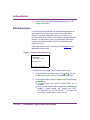
Figure 1-1 Start Screen
PowerNet Twin Client
(C) 1991-1998, Connect
Press Any Key to Continue
For all Falcons: Press uppercase <C> to enter configuration screen.
The PowerNet TN Configuration Menu is shown in Figure 1-2 on
page 1-8. Use the Falcon’s up and down cursor keys ( and ) to
navigate the menu, and press ENTER for the desired option.
PowerNet Twin Client User Guide
< 1-7 >
Getting Started
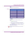
Figure 1-2 Configuration Menu
Edit Functions
Edit IP
Edit Host List
Edit Radio
Run Survey
Switch Modes
Run Emulator
Exit
Edit IP
The Edit IP option sets up the IP address for each Falcon.
Figure 1-3 Sample IP Address Configuration Screen
IP nnn.nnn.nnn.nnn
SN nnn.nnn.nnn.nnn
RT nnn.nnn.nnn.nnn
<F3> Save <F7> Quit
Complete the following steps to configure the Falcon’s IP address:
1.
Using the Falcon’s up and down-arrow keys ( and ), highlight
the Edit IP function and press the ENTER key.
2.
Enter the Falcon’s IP address in the IP field and press the ENTER
key.
3.
Enter the Falcon’s subnet mask in the SN field and press the
ENTER key.
4.
Enter the Falcon’s router (gateway) IP address in the RT field and
press the ENTER key.
If the Falcon does not require a router (gateway) IP address, enter
0.0.0.0 in the RT field and press the ENTER key.
< 1-8 >
PowerNet Twin Client User Guide
Configure PowerNet Twin Client
5.
Press the <F3> key to save the IP settings and return to the
Configuration Menu.
Consult the IS manager at the installation site to coordinate the IP addresses
of the Falcons with the rest of the network installation.
For DHCP support: Enter 0.0.0.1 as the IP address. (Datalight™
TCP/IP stack only)
Edit Host List
PowerNet Twin Client supports up to five host machines. The host list
option sets the IP address for each host machine. A sample host list
screen is displayed in Figure 1-4.
Figure 1-4 Sample Host List Configuration Screen
Host n
IP nnn.nnn.nnn.nnn
Port nnnn
<F3> Save <F7> Quit
Complete the following steps to configure the host’s IP address:
1.
Using the Falcon’s up and down-arrow keys ( and ), highlight
the Edit Host List function and press the ENTER key.
2.
Enter the IP address of the host application server in the IP field
and press the ENTER key.
3.
Enter the port for the telnet session in the Port field and press the
ENTER key. The default port value is 23.
w Contact the network administrator if there is any confusion on
the port value.
4.
Repeat steps 2 and 3 until each host IP address has been entered.
PowerNet Twin Client User Guide
< 1-9 >
Getting Started
5.
Press the <F3> key to save the host settings and return to the
Configuration Menu.
Edit Authorization
Once the Falcon’s IP address and host machine address have been set,
each PowerNet Twin Client terminal must then be authorized to
operate. The terminal authorization code, which is based on the
terminal’s unique serial number or MAC address, is provided with each
terminal. If an authorization code is not included with the terminal,
complete and send the PowerNet Twin Client authorization code
request form to PSC.
Use the authorization screen to enter the code. See Figure 1-5 for a
sample authorization screen.
Figure 1-5 Sample Authorization Screen
F0003196
Authorization
39DB-0989-AA21
Not Authorized
<F3> Save <F7> Quit
Complete the following steps to enter the authorization code:
< 1-10 >
1.
Using the Falcon’s up and down-arrow keys ( and ), highlight
the Edit Authorization function and press the ENTER key.
2.
Enter the authorization code in the Authorization field and press
the ENTER key.
w The authorization code must be entered exactly as it is
presented.
w When the authorization code is entered and the ENTER key
pressed, a status prompt will change from “NOT
AUTHORIZED” to “TN ADVANCED”. If this status does
not change, the authorization code is incorrect.
PowerNet Twin Client User Guide
Configure PowerNet Twin Client
3.
Press the <F3> key to save the authorization code and return to
the configuration menu.
Failure to authorize a Falcon properly will prevent the unit from operating
with PowerNet Twin Client. Contact a reseller for assistance if there are any
problems with authorization.
PowerNet Twin Client Demo Mode
PowerNet Twin Client runs only in demo mode if no authorization code
is entered or if an incorrect authorization code is entered. The client
program will have all of the normal functionality of the registered
product but will cease operation after thirty minutes.
A “RECOVERABLE ERROR” message will be displayed if there is any
attempt to run the emulator. Press any key to connect the client to the
host in demo mode.
PowerNet Twin Client User Guide
< 1-11 >
Getting Started
Running Emulator
After configuring the Falcon data terminal (IP Address, host list, and
authorization code), login to the host application.
Complete the following steps to start the PowerNet Twin Client
emulator:
1.
Perform a safe-boot of the terminal.
w For Falcon 315 and 325: Press <CTL><ALT><DEL>. When
the “Wait...” message appears, press <ESC><DEL>.
w For Falcon 335: Press <CTL><ALT><DEL>. When the
“Wait...” message appears, press <ESC><SPACE>.
w For Falcon 615/655 (6x5): Press <F5> at the starting MSDOS prompt.
w For Falcon 3xx only: The terminal will emit a low tone
followed by a higher pitched tone if the safe-boot is successful.
2.
After receiving the “Any Key to Continue” message, press any key
to connect to the application host server.
If the first host connection fails, PowerNet Twin Client will try to
connect to the second defined host. If all of the defined hosts fail
to connect, an error will be displayed.
< 1-12 >
PowerNet Twin Client User Guide
Viewport Panning
Viewport Panning
If a screen of text is larger than the terminal’s screen, it is still possible to
pan the viewable screen on a Falcon (viewport).
For the Falcon 315 and 315: Press <CTL><(directions)arrow>.
For the Falcon 335: Press <ALT><(directions)arrow>.
It is highly recommended that the screens be redesigned to fit within the
display area of the terminal.
PowerNet Twin Client User Guide
< 1-13 >
2
Configuration Utility
The PowerNet Twin Client Configuration utility sets up the PowerNet
Twin Client application for Falcon terminals. The Configuration utility
provides the tools to quickly modify RF, scanner, keyboard, and display
settings. After a configuration has been created, the same settings can be
loaded onto additional Falcon units.
CHAPTER CONTENTS
Starting Configuration Utility...........................<2-3>
Set Emulation and Servers.................................<2-4>
Emulation
Host Servers
New-Environ Setting
Configuring PowerNet Twin Client ...................<2-7>
The Keyboard Tab
The Display Tab
The Scanner Tab
The Log Levels Tab
The Polling/Timers Tab
The Alarm Tab
The Printer Tab
The Misc Tab
Load New Configuration...................................<2-34>
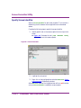
Starting Configuration Utility
Starting Configuration Utility
Complete the following steps:
1.
Verify that the Falcon is properly attached to the host PC.
2.
Press the Windows Start button.
3.
Select Programs and then select PowerNet TN.
4.
Select Configuration Utility to start the PowerNet Twin Client
Windows Configuration utility.
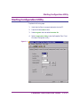
Figure 2-1
PowerNet Twin Client User Guide
< 2-3 >
Configuration Utility
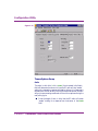
Set Emulation and Servers
Before configuring the PowerNet Twin Client emulator to work with the
target server, select the appropriate emulation type and identify host
servers.
Emulation
PowerNet Twin Client supports several terminal emulation modes that
connect to a variety of host application terminals.
1.
From the Terminal menu, select Emulation.
2.
Select the proper emulation for the application (refer to Table 2-1
for available values).
Depending upon the selected emulation value, configurable fields in the
PowerNet Twin Client Configuration utility will either be enabled or
disabled (grayed out).
3.
Press the OK button.
Emulation Values
Table 2-1
Default
VT100
Available Values
VT100
VT200
HP700
IBM3270
IBM5250
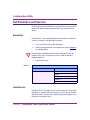
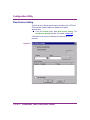
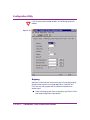
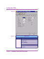
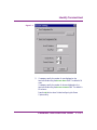
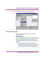
Host Servers
PowerNet Twin Client supports up to five host machines. This provides
redundancy in the event that the connection to one of the host machines
should fail. Define the host list by completing the following steps in the
PowerNet Configuration utility:
< 2-4 >
PowerNet Twin Client User Guide
Set Emulation and Servers
1.
From the Terminal menu, select Servers.
2.
Press the Add button.
3.
Enter a name for the host server in the Server Name field.
4.
Enter the IP address for the host server in the IP Address field.
If the network supports DNS and the server name is known, enter the server
name in the Server Name field and press the Lookup button to automatically
populate the IP Address field.
Figure 2-2
5.
If necessary, enter the host server’s port value for a telnet session
(Do not change this value unless otherwise instructed by the
system administrator).
6.
Repeat steps 2 — 5 to add additional host servers to the server list.
7.
Press the OK button after completing the server list.
PowerNet Twin Client User Guide
< 2-5 >
Configuration Utility
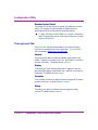
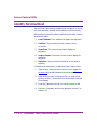
New-Environ Setting
The New Environ settings supports terminal scripting of the 3270 and
5250 emulation types by application developers or system
administrators.
l
From the Terminal menu, select New Environ Setting. The
New-Environ Settings window is illustrated in Figure 2-3.
These options can script the Variable and the Value for any or all
terminals
Figure 2-3
< 2-6 >
PowerNet Twin Client User Guide
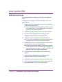
Configuring PowerNet Twin Client
Configuring PowerNet Twin Client
PowerNet Twin Client can be operated without any adjustments to the
default configuration.
The Configuration Utility tabs include the Keyboard, Display,
Scanner, Log Levels, Polling/Timers, and Alarm settings. These
settings can be configured to work with a number of host applications as
well as specific automated data collection processes (i.e. scanning).
Grayed out fields in the PowerNet Twin Client Configuration utility are
not configurable.
PowerNet Twin Client User Guide
< 2-7 >
Configuration Utility
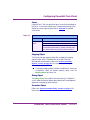
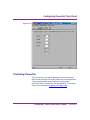
The Keyboard Tab
The Keyboard Configuration Tab modifies how the keyboard
interacts with the host application. The Keyboard Configuration Tab
is illustrated in Figure 2-4.
.
Figure 2-4
End Key
Select the key from the pull-down list that will be the End Key. The
terminal session is terminated when the End Key is pressed.
< 2-8 >
PowerNet Twin Client User Guide
Configuring PowerNet Twin Client
Auto Send Key
The Auto Send Key automatically processes an entry when the
maximum amount of data allowed in a field is inputted. For example, if
the maximum input field for a Social Security number is 11 characters
(###-##-####) the auto send key will process the entry after 11
characters have been entered.
l
Select the Auto Send Key from the Auto Send Key pull-down
list.
Key Click
The Key Click feature enables an audible “click” that verifies when a key
on the Falcon has been pressed.
l
Check the box to enable this feature.
Case Conversion
Case Conversion controls the case of data sent to the host application.
For example, if the host application requires all data entry to be upper
case, PowerNet Twin Client will convert the entry TestEntry to
TESTENTRY if the Case Conversion feature is set to Upper.
Conversely, if the Case Conversion feature is set to Lower, entries will
be converted to lower case
.
Table 2-2
Case Conversion Values
Default
None
Available Values
None: No case conversion will be applied to the entered
text.
Upper: All entered text will be converted to upper case
characters before being sent to the host application.
Lower: All entered text will be converted to lower case
characters before being sent to the host application.
PowerNet Twin Client User Guide
< 2-9 >
Configuration Utility
Mapping Object
The Mapping Object links the keys on the Falcon to a specified terminal
key. For instance, a mapping object can specify that the keypress
<CTL><V> on the Falcon will be the <pf24> key stroke on the host
application. Refer to the “Keyboard Mapping” section on page 3-5
for information on building and editing Mapping Object files.
l
To apply a Mapping Object to a current configuration, select the
appropriate map object from the Mapping Object pull-down list.
Macro Object
A Macro Object links a pre-defined macro or a sequence of key strokes
to a single key on the Falcon. Refer to the “Keyboard Macros”
section on page 3-3 for information on building and editing Macro
Object files.
l
To apply a Macro Object to a current configuration, select the
appropriate macro object from the Macro Object pull-down list.
Advanced
Selecting the Advanced button displays the Advanced 3270 Keyboard
screen (Only available with 3270 emulation). Figure 2-5 illustrates this
screen.
Setting the Attribute and Last Field Keys is a function best performed by the
system administrator.
Figure 2-5
< 2-10 >
PowerNet Twin Client User Guide
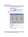
Configuring PowerNet Twin Client
The Display Tab
The Display Tab modifies how the Falcon display interacts with the
host application. The Display Tab is illustrated in Figure 2-6.
Figure 2-6
Quadrant Mode
There are two options when a Falcon installation requires converting the
host application screen to the size of the display on the terminal:
l
Reformat the host application display so it can be contained on an
appropriately sized screen.
l
Utilize the various PowerNet Twin Client Quadrant Modes to
control the movement of the viewport.
PowerNet Twin Client User Guide
< 2-11 >
Configuration Utility
l
Select the mode from the Quadrant Mode pull-down list that
best meets the installation requirements.
Table 2-3
Quadrant Mode Values
Default
Off
Available Values
Hard: Positions on a quadrant boundary regardless of
input field boundaries. Panning keys are disabled.
Lock: Locks the terminal display to host display row and
column coordinates (see Lock Row and Lock Column
below).
Off: Disables quadrant processing; the client attempts
to center the current host input field in the terminal
display
On: Enables quadrant processing; however, input fields
that cross quadrant boundaries result in a shift to the left
or right
Soft: Positions on a quadrant boundary regardless of
input field boundaries. Viewing keys are enabled.
Lock Row
If the Lock Quadrant Mode was selected, define the row (coordinate y)
where the display will begin. (Refer to the “Quadrant Mode” section
on page 2-11 for more information.)
l
Enter the desired row value in the Lock Row field.
Table 2-4
< 2-12 >
Lock Row Values
Default
0
Available Values
0 - 25
PowerNet Twin Client User Guide
Configuring PowerNet Twin Client
Figure 2-7 The position of a locked quadrant is determined by the specified coordinates of the upper
left corner of the desired area.
For example, the locked quadrant is defined by the coordinates x, y:
Row (y): 10
Column (x): 15
x, y
Lock Column
If the Lock Quadrant Mode was selected, define the column
(coordinate x) where the display will begin. (Refer to the “Quadrant
Mode” section on page 2-11 for more information.)
l
Enter the desired column value in the Lock Column field.
Table 2-5
Lock Column Values
Default
0
Available Values
0 - 80
Scroll Mode
If the Lock Quadrant Mode was selected, the host application display
can be scrolled on the viewport. (Refer to the “Quadrant Mode”
section on page 2-11 for more information.) The possible scroll values
are shown in Table 2-6 on page 2-14.
l
Select the scroll method from the Scroll Mode pull-down list that
best meets the application requirements.
PowerNet Twin Client User Guide
< 2-13 >
Configuration Utility
Table 2-6
Scroll Mode Values
Default
Full
Available Values
Full: Terminal display is moved in
full-screen increments.
Falcon 315: Scrolls down 8 rows
and scrolls right 20 columns.
Falcon 325/335: Scrolls down 16
rows and scrolls right 21 columns.
Falcon 6x5: Scrolls down 24 rows
and scrolls right 80 columns.
Half: Terminal display is moved in
half screen increments.
Falcon 315: Scrolls down 4 rows
and scrolls right 10 columns.
Falcon 325/335: Scrolls down 8
rows and scrolls right 10 columns.
Falcon 6x5: Scrolls down 12 rows
and scrolls right 40 columns.
Language
PowerNet Twin Client supports several different languages. (Refer to
Table 2-7 for a list of available values.) The selected language defines the
character set used for terminal error message displays.
l
Select the language from the Language pull-down list that best
meets the application requirements.
Table 2-7
Language Values
Default
English
Available Values
English:
French:
German:
Spanish:
Danish:
Swedish:
< 2-14 >
PowerNet Twin Client User Guide
Configuring PowerNet Twin Client
Cursor
PowerNet Twin Client can adjust the type of cursor that is displayed on
the Falcon. In most cases, a Soft cursor is the best value because it will
display the current keyboard state. Refer to Table 2-8 for available
cursor values.
.
Table 2-8
Cursor Values
Default
Hard
Available
Values
Hard: Displays a blinking block cursor.
Hide: Cursor is not displayed.
Soft: Displays a software-generated cursor that displays
the current keyboard state (i.e. shifted, controlled, FN1,
etc.). See the Falcon RF manual for more information.
Mapping Object
The Display character mapping object file is created by the display
mapping object editor. The Edit button at the end of the field
automatically starts the editor. Refer to the “Advanced Display
Options” section on page 4-1 for information on building and
editing Mapping Object files.
l
If a display mapping object has been pre-defined for the current
configuration, select the desired mapping object from the
Mapping Object pull-down list.
Dialog Object
The Dialog Object file is used for terminal scripting. This feature is
only for advanced terminal system administrators with knowledge and
experience in developing terminal scripts.
Formatter Object
Refer to the “Screen Formatter Utility” section on page 8-1 for
more information.
PowerNet Twin Client User Guide
< 2-15 >
Configuration Utility
l
To apply a Formatter Object to a current configuration, select
the appropriate object file from the Formatter Object pull-down
list.
Relocation Options Group
This feature will relocate a selected screen section from one area of the
host application screen to the locked screen section that will be displayed
on the Falcon.
Figure 2-8
x, y
Destination
Source
Source
The value entered in the Source field determines the first host
application row to be relocated.
l
Enter the first row of the host application screen to be relocated in
the Source field.
Destination
The value entered in the Destination field determines where the
relocated lines will be repositioned on the client screen.
l
< 2-16 >
Enter the row to which the source row(s) will be relocated on the
client screen in the Destination field.
PowerNet Twin Client User Guide
Configuring PowerNet Twin Client
Row Count
It is possible to move multiple rows to a new destination. Beginning
with the source row, enter the number of rows that will be relocated in
the Row Count field.
Move Blank
Use the Move Blank option to specify whether blank rows will be
relocated to the specified destination.
l
Checking the Move Blank checkbox enables the relocation of
blank rows.
Double High
To display the host application using double-high characters, select the
Double High checkbox.
Enabling the Double High checkbox will reduce the display from 8 rows to 4
rows on the Falcon 315. On the Falcon 325/335, the display will be reduced
from 16 to 8. This feature is not available on the Falcon 6x5.
Double Wide
To display the host application using double-wide characters, select the
Double Wide checkbox.
Enabling the Double Wide checkbox will reduce the number of columns by
half.
Reverse Video
Some terminal host applications use reverse text for added visual
characteristics. This is often done to draw attention to warnings and/or
application controls. To enable this function, select the Reverse Video
checkbox.
Wait Message
The Wait Message checkbox enables or disables the display of the
“WAITING FOR DATA” message on the terminal. A “WAITING
FOR DATA” message will be displayed when the data is locked on the
PowerNet Twin Client User Guide
< 2-17 >
Configuration Utility
server. Typically, this occurs when the data is already in use and the
telnet session is waiting for the data to be released.
Advanced VTERM Display
Pressing the Advanced button will display the Advanced VTERM
Display window. (Figure 2-9 illustrates the Advanced VTERM
Display Window.) Checked items will appear as reverse video.
These values should only be modified by experienced terminal emulation
users.
Figure 2-9
Attribute Mask
The Attribute Mask selection determines how reverse video fields from
the host will be displayed on the terminal.
Field Mask
The Field Mask selection determines the terminal display of video fields
that are sent in the Block Mode.
< 2-18 >
PowerNet Twin Client User Guide
Configuring PowerNet Twin Client
Blink Mask
The Blink Mask selection determines how blinking video fields will be
displayed on the terminal.
The Scanner Tab
The Scanner Tab sets the parameters of how the Falcon terminal’s
scanner interacts with the host application. The Scanner Tab is
illustrated in Figure 2-10 on page 2-20.
Send Key
Similar to the Auto Send Key, the Send Key automatically processes a
data entry when an input field has received scanned input. For example,
if a product number is scanned, the send key would be processed
immediately after the scan.
l
Select the key that will be specified as the Send Key from the
Send Key pull-down list.
Scan Ahead
This feature is not programmable and is grayed out.
Truncation
If the length of the scanned input is greater than the length of the input
field, the Truncation feature will reduce the length of the scanned input
to match the target input field.
l
Enable the Truncation field to activate the PowerNet Twin Client
Truncation feature.
PowerNet Twin Client User Guide
< 2-19 >
Configuration Utility
If the Truncation feature has been enabled, the Field Wrapping feature is
disabled.
Figure 2-10
Stripping
Spaces and underscores that trail scanned input will cause data integrity
problems when entered into the target application. PowerNet Twin
Client can strip trailing spaces and/or underscore characters from
scanned input.
l
< 2-20 >
Select the stripping value from the Stripping pull-down list that
best meets the application requirements.
PowerNet Twin Client User Guide
Configuring PowerNet Twin Client
Table 2-9
Stripping Values
Default
Off
Available Values
Off: Don’t strip.
Space: Strip spaces.
Score: Strip underscores.
Both: Strip both spaces and underscores.
Binary-128
The Binary-128 checkbox enables or disables the processing of binary
code 128 bar codes on the terminal. The default value is off.
Data Mapping Object
The PowerNet Twin Client package can map the incompatible extended
characters of the terminal server to the DOS character set on the Falcon.
It is then possible to make a change in data entry without requiring any
change to the host application. Refer to the “Data Mapping Object”
section on page 5-3 for more information on building and editing the
Data Mapping Object file.
l
To apply a Data Mapping Object to a current configuration,
select the appropriate mapping object from the Data Mapping
Object pull-down list.
Data Editor Object
The Data Editor Object feature edits scanned data before it is entered
into the host application. For example, if a scanned entry needs to be
modified or parsed, PowerNet Twin Client will handle this via the Data
Editor Object. Refer to “Build Display Mapping Object File” on
page 4-4 for more information on building and editing the Data Editor
Object file.
l
To apply a Data Editor Object to a current configuration, select
the appropriate mapping object from the Data Editor Object
pull-down list.
PowerNet Twin Client User Guide
< 2-21 >
Configuration Utility
Decoder Control Object
The scanner of the Falcon can be controlled via the Decoder Control
Object. For example, this feature enables or disables particular
symbologies as well as controls different symbology options.
l
To apply a Decoder Control Object to a current configuration,
select the appropriate control object from the Decoder Control
Object pull-down list.
The Log Levels Tab
The Log Levels Tab sets the parameters for the terminal’s logging
functions to track data within the host application. The Log Levels
Tab is illustrated in Figure 2-11 on page 2-23
.
General
The General pull-down list defines the general logging level for the
handler. There are 10 log levels, from 0 to 9, with a level of 9 collecting
the most information. The default value is 0 (zero).
Display
The Display pull-down list defines the level of logging for host and
terminal display logging. A level higher than 7 results in a hex dump of
the displays. The default value is 0 (zero).
Formatter
The Formatter pull-down list defines the level of logging for the screen
formatting routines. The default value is 0 (zero).
Dialog
The Dialog pull-down list defines the level of logging for dialog
routines. The default value is 0 (zero).
< 2-22 >
PowerNet Twin Client User Guide
Configuring PowerNet Twin Client
Figure 2-11
The Polling/Timers Tab
The Polling/Timers Tab sets the parameters on how the terminal’s
radio timer and polling functions will interact with the host application.
These timing parameters can be modified to tune the radio's
performance when interacting with the host application. The Polling/
Timers Tab is illustrated in Figure 2-12 on page 2-24.
PowerNet Twin Client User Guide
< 2-23 >
Configuration Utility
Figure 2-12
Timers Options Group
Radio
The value, in clock ticks (1 tick = 55ms), that is entered in the Radio
field will determine the amount of time the RF radio will stay “awake”
waiting for a transaction response initiated by the host. If no response is
received from the host server by the time this value has expired, the radio
will go into power savings mode and will check for a response during the
next polling cycle.
l
< 2-24 >
Enter the length of time, in ticks, that the RF radio will remain
“awake” waiting for a response from host server in the Radio
field.
PowerNet Twin Client User Guide
Configuring PowerNet Twin Client
Increasing the Radio value will improve network performance, but will also
reduce the battery life.
Power
The value, in seconds, entered in the Power field will determine the
length of terminal inactivity from the scanner, keyboard, or radio. The
Falcon will enter Sleep Mode during periods of inactivity (see the Falcon
User Guide for more information on the Falcon Sleep Mode).
l
Enter the length of inactive time, in seconds, that initiates the
Falcon entering Sleep Mode in the Power field.
Backlight
The value, in seconds, entered in the Backlight field determines how
long the Falcon backlight will stay on after keyboard or scanner input.
Refer to Table 2-10 for specific values.
l
Enter the length of time, in seconds, that the Falcon backlight will
stay on, after input in the Backlight field.
.
Table 2-10
Backlight Values
Default
0
Available Values
0: Backlight does not turn on after keyboard or scanner
input.
> 0: Backlight will stay on for the specified amount of
time (in seconds) after keyboard or scanner input.
30: Maximum value.
AP Polling Options Group
These settings are only available when using a Symbol Spectrum 24equipped Falcon RF unit.
The Symbol Spectrum 24 radio has an advanced power management
algorithm that controls the radio polling interval.
After a transmission from the radio, the radio will immediately poll for a
transmission from the host server. If no transmission was received, the
PowerNet Twin Client User Guide
< 2-25 >
Configuration Utility
interval between polling increases and continues until such time as the
maximum interval has been reached.
The optimum power saving/performance configuration uses a dynamic
algorithm for determining the timeout period. For example, a timeout
period of 1 second can be specified, but as time continues and no traffic
is present, the timeout value increases. This dynamic scenario is
controlled with the Primary/Min, Max and Algorithm settings, as
illustrated in Figure 2-13.
Maximum
Primary/Min
Figure 2-13
Polling Frequency over Time (with Algorithm 11)
Primary/Min
If the Algorithm value is set to 11, the value set in the Primary/Min
Field determines what the minimum beacon interval will be. For
example, if the terminal is to begin listening every 200ms, set the
Primary/Min value to 2 (1:100 ms).
l
Enter the minimum polling time, in seconds, for the Symbol
radio in the Primary/Min field.
Max
If the Algorithm value is set to 11, the value set in the Max field
determines what the maximum beacon interval will be. For example, to
set the longest duration between listens to 1 second, the value must be
set to 10.
l
Enter the maximum polling time, in seconds, for the Symbol
radio in the Max field.
Algorithm
The Algorithm value controls how often the radio listens for a beacon.
A value between 1 and 10 specifies a static polling period:
(1=100ms, 2=200ms, 9=900ms, and 10=1 sec)
< 2-26 >
PowerNet Twin Client User Guide
Configuring PowerNet Twin Client
11 specifies the dynamic polling period. The default is 0 (zero).
l
Enter the algorithm value the Symbol radio will use in the
Algorithm field.
Proxim
The NET.CFG file for Proxim equipped Falcon RF units is optimized
for maximum performance and battery life. To modify the Proxim
power management values, it is necessary to edit the NET.CFG file.
Review the Falcon RF User Guide for more information.
The Alarm Tab
The Alarm Tab sets the parameters on how the terminal’s alarm (beep)
functions when interacting with the host application. The Alarm Tab is
illustrated in Figure 2-14 on page 2-28.
Mode
PowerNet Twin Client offers several different alarm modes. In
environments where a tone may be inaudible, the scan indicator (alarm
mode) can be set to provide a visual alarm. Refer to Table 2-11 on
page 2-28 for specific values.
l
From the Mode pull-down list, select the alarm mode.
The alarm mode must be set to spec1 or spec2 for duration to take
effect.
PowerNet Twin Client User Guide
< 2-27 >
Configuration Utility
Figure 2-14
Table 2-11
Mode Values
Default
Bell
Available Values
Bell: Enables the audible alarm as a double beep.
Both: Enables the double beep and the scan indicator
light as the alarm.
Flash: Enables the scan indicator light as the alarm
with no audible alarm.
Off: Disables the audible alarm.
Spec1: Enables the audible alarm as a single beep.
Spec2: Enables the single beep and the scan indicator
as the alarm.
< 2-28 >
PowerNet Twin Client User Guide
Configuring PowerNet Twin Client
Volume
The Volume adjusts the volume value of the audible alarms.
l
Select the desired alarm volume from the Volume pull-down list.
Table 2-12
Volume Values
Default
Hi
Available Values
Hi
Low
Duration
The Duration value defines the duration of the audible alarm on the
terminal in milliseconds.
l
Enter the duration, in milliseconds (i.e. 500 ms for .5 seconds),
for the audible alarm in the Duration field.
Frequency
The Frequency value defines the alarm frequency and is defined in
hertz. The default value is 2048.
l
Enter the frequency, in hertz, of the audible alarm in the
Frequency field.
Scan Duration
The Scan Duration value defines the duration of the audible alarm that
is generated by a successful scan operation on the terminal in
milliseconds.
l
Enter the scan duration, in milliseconds (i.e. 500 ms for.5
seconds), in the Scan Duration field.
Scan Frequency
The Scan Frequency value defines the scan alarm frequency and is
defined in hertz. The default value is 0 (zero).
l
Enter the frequency, in hertz, of the audible alarm in the
Frequency field.
PowerNet Twin Client User Guide
< 2-29 >
Configuration Utility
Define a scan frequency value that is different from the value in the
Frequency field. Different tones allow the user to distinguish between a
successful scan and an error condition.
Allow Multiple
Select the Allow Multiple checkbox to enable the Falcon terminal to
process any multiple alarms sent sequentially and without a break from
the host server. If the checkbox is disabled, only a single alarm will
sound. (Figure 2-14 on page 2-28 illustrates this checkbox.)
The Printer Tab
The Printers Tab lists the printers that can be used with the Falcon.
The Printers Tab is illustrated in Figure 2-15.
Figure 2-15
< 2-30 >
PowerNet Twin Client User Guide
Configuring PowerNet Twin Client
Type
Select a printer from the Type pull-down list.
Table 2-13
Printer Type Values
Default
None
Available Values
None
Ps1000
Ps1001
Ps1004
Monarch
Pddumb
Comtec
Codewriter
Comtec(s)
Rascal
Init Object
The Init Object pull-down list selects an initialization file for the
printer.
1.
2.
Press Edit to open a dialog box.
Select a file to edit from the pull-down list or create a new file.
w The file must contain the initialization commands for the
specific printer.
Refer to the printer’s documentation for information on defining and
editing the printer’s initialization file.
Be sure to enter a semicolon at the end of each line in the initialization
commands.
PowerNet Twin Client User Guide
< 2-31 >
Configuration Utility
The Misc Tab
The Misc Tab includes miscellaneous configuration features for specific
emulation values.
Extended Command Group (3270, 5250 only)
Start
Start specifies a unique character sequence within the host display,
which turns all subsequent characters into an Extended Command.
Only an End sequence will terminate the Extended Command. The
default is blank which indicates that the option is not in use.
End
End specifies a unique character sequence that terminates the Extended
Command.
Data Stream Group (3270 only)
Send All MDT
The Data Stream Group determines how fields with the Modified Data
Tag bit set are selected for transmission to the host application.
If set to No, only unprotected fields modified by the terminal operator
are transmitted.
If set to Yes, all fields with the MDT bit set (protected and
unprotected) are transmitted.
The default is yes.
Send NULL
If checked, all null characters are transmitted to the host.
< 2-32 >
PowerNet Twin Client User Guide
Configuring PowerNet Twin Client
Answerback (VT100, VT220, HP700 only)
Note: AS400 hosts must check this field.
An answerback is a message returned to the host application in response
to a request
(CTRL-E).
l
Octal escape sequences may be embedded (\nnn).
l
The default value is blank.
l
Inserting the sequence $1 into the answerback string causes
VTerm to substitute the 3-digit IP address for Access Point
terminals.
The following answerback examples send the indicated response
back to the host:
answerback = Hello World
Sends Hello World as a response.
answerback = $1
Sends three digit ID i.e., 065, 066, etc.
answerback = RF$1
Sends RFXXX where XXX is ID.
answerback = RF$1\015
PowerNet Twin Client User Guide
< 2-33 >
Configuration Utility
Load New Configuration
After creating and saving the PowerNet Twin Client configuration, load
the new configuration to the terminal.
Complete the following steps to load a new PowerNet Twin Client
configuration:
< 2-34 >
1.
Perform a safe-boot of the terminal.
w For Falcon 315 and 325: Press <CTL><ALT><DEL>. When
the “Wait...” message appears, press <ESC><DEL>.
w For Falcon 335: Press <CTL><ALT><DEL>. When the
“Wait...” message appears, press <ESC><SPACE>.
w For Falcon 615/655 (6x5): Press <F5> at the starting MSDOS prompt.
w For Falcon 3xx only: The terminal will emit a low tone
followed by a higher pitched tone if the safe-boot is successful.
2.
Select Send Setup Files to Terminal from the Terminal menu
in the PowerNet Twin Client Windows configuration utility.
3.
Type LD at a c:\ prompt on the Falcon and press the ENTER.
w If the terminal currently has PowerNet Twin Client running,
press the <F10> key on the terminal to terminate the current
session.
w Falcon 315 Only: When the “Any Key to Continue” message
appears, press <ALPHA><CAPS><C> and select Exit; this
will return the c:\ prompt.
4.
From the PC, select the OK button after confirming that the LD
on the terminal has started.
5.
From the PC, select the OK button after receiving the “Transfer
Complete” message.
6.
Perform a safe-boot as presented in step 1.
PowerNet Twin Client User Guide
3
Advanced
Keyboard Options
PowerNet Twin Client provides several advanced keyboard options to
assign custom macros to a specific Falcon key or remap a Falcon key to
provide greater functionality with host applications.
CHAPTER CONTENTS
Keyboard Macros ..............................................<3-3>
Falcon Key Codes
Build Keyboard Macro Object File
Keyboard Mapping ...........................................<3-5>
Define Keyboard Mapping Object
Keyboard Macros
Keyboard Macros
PowerNet Twin Client can create and assign macros to the Falcon
keyboard. These macros are defined within a Keyboard Macro Object
file.
Falcon Key Codes
Macro Object files are constructed using the following syntax:
<key code>=<macro string>;
<key code> is the Falcon key code. (Refer to Table 3-1 on page 3-4
for the specific Falcon key codes.)
For example, to send the text vt100 followed by ENTER when a user
presses the <F9> key, define the following in the Macro Object file:
pf9=vt100\015; (\015 is the octal code for ENTER)
Multiple keyboard macros can be defined in a single Macro Object file.
Each line of the Keyboard Macro Object file must be terminated by a
semicolon.
pf1=login5\015;
pf2=passwd5\015;
pf3=vt100\015;
pf4=appname\015;
Build Keyboard Macro Object File
To build a Keyboard Macro Object file, complete the following steps:
1.
Verify that the Keyboard tab of the PowerNet Twin Client
Configuration utility is selected.
2.
Press the Edit button next to the Macro Object pull-down list.
3.
Enter a name for the macro object file in the File Name field and
press the Open button.
4.
Repeat the procedure for defining keyboard macros as shown in
the section on Falcon Key Codes.
PowerNet Twin Client User Guide
< 3-3 >
Advanced Keyboard Options
5.
When finished defining the macros, select Exit from the File
menu.
6.
Press the Yes button to save the macros that have been defined.
7.
Select the saved file from the Macro Object pull-down list.
8.
Save the PowerNet Twin Client configuration by selecting Save
from the main screen File menu.
The selected keyboard macros will be loaded the next time the Falcon
terminal is programmed using the PowerNet Twin Client Configuration
utility.
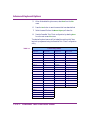
Falcon Key Codes
Table 3-1
< 3-4 >
Keypress
Key Code
Keypress
Key Code
<FN1>1
pf1
<left arrow>
left_a
<FN1>2
pf2
<right arrow>
right_a
<FN1>3
pf3
<down arrow>
down_a
<FN1>4
pf4
<up arrow>
up_a
<FN1>5
pf5
<CTL>A
ctl_a
<FN1>6
pf6
<CTL>B
ctl_b
<FN1>7
pf7
<CTL>C
ctl_c
<FN1>8
pf8
<CTL>D
ctl_d
<FN1>9
pf9
<CTL>F
ctl_f
<FN1>0
pf10
<CTL>N
ctl_n
<ALT>1
pf11
<CTL>O
ctl_o
<ALT>2
pf12
<CTL>R
ctl_r
<ALT>3
pf13
<CTL>W
ctl_w
<ALT>4
pf14
<CTL>X
ctl_x
<ALT>5
pf15
<CTL>Y
ctl_y
<ALT>6
pf16
<ALT>7
pf17
<ALT>8
pf18
<ALT>9
pf19
<ALT>0
pf20
PowerNet Twin Client User Guide
Keyboard Mapping
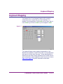
Keyboard Mapping
The PowerNet Twin Client Keyboard Mapping utility can add or
modify the function of a particular key or key combination. For
example, if the host application utilizes <F24> and the Falcon does not
have a <F24> key, the Falcon’s <F24> key can be mapped to <F24>.
Figure 3-1
The Keyboard Mapper contains a graphical representation of the
selected Falcon keyboard on the left of the screen. Key map assignments
are located on the right side of the screen. The key map assignment is
defined by the new value of the key (selected from the Transmit column)
and the transmission method (selected from the Mode column). Refer to
Table 3-2 on page 3-6 for specific transmission mode values.
PowerNet Twin Client User Guide
< 3-5 >
Advanced Keyboard Options
Transmission Mode Values
Table 3-2
Default
Blank
Available
Values
local: Handle the specified key locally on the terminal, send (if
required, as in the case of alphanumeric characters and
symbols) when <enter> on the terminals pressed.
xmit: Transmit the key immediately to the host
lamp: Turn on the terminal’s backlight
light: Lighten the display contrast.
dark: Darken the display contrast.
noop: Don’t do anything
edleft*: Non-destructive backspace (move) to the left of the
cursor within a field (operates like a left arrow key)
edrite*: Non-destructive space (move) to the right of the cursor
within a field (operates like a left arrow key)
edbksp*: Destructive backspace (move) to the left of the cursor
within a field
edefld*: Edit mode.
edeeof*: Destructive space (move) to the right of the cursor
within a field, to the end of the field.
lhelp: This key, when pressed, displays the terminal ID, date,
time, and WHIP/WHAP version number.
scan: Set a key that, when pressed, triggers the scanner to
scan.
* = The cursor must be in block mode for these transmission modes to operate.
< 3-6 >
PowerNet Twin Client User Guide
Keyboard Mapping
Define Keyboard Mapping Object
Complete the following steps to map a Falcon key:
1.
Verify that the Keyboard tab of the PowerNet Twin Client
Configuration utility is selected.
2.
Press the Edit button next to the Mapping Object pull-down list.
3.
Select the Falcon Type.
4.
Select the key from the simulated Falcon keyboard that is to be
modified. Verify the selection in the Unmodified field to the
right of the keyboard.
5.
Select the new keyboard value from the Transmit column that
corresponds with the keyboard state that is to be modified.
6.
Select the mode that will be applied to the mapped keyboard
value.
7.
After defining the keyboard mapping objects, select Exit from the
File menu.
8.
Enter a name for the mapping object file in the File Name field
and press the Save button.
9.
Select the file from the Mapping Object pull-down list.
Save the PowerNet Twin Client configuration by selecting Save from
the File menu. The defined keyboard mapping objects will be loaded
the next time the Falcon terminal is programmed using the PowerNet
Twin Client Configuration utility.
PowerNet Twin Client User Guide
< 3-7 >
4
Advanced
Display Options
PowerNet Twin Client can map the unsupported characters of the
terminal server to the Falcon character set.
CHAPTER CONTENTS
Display Mapping Object ...................................<4-3>
Character Sets
Build Display Mapping Object File
Display Mapping Object
Display Mapping Object
This feature is for experienced terminal system administrators only.
Character Sets
Character sets between the Falcon and terminal servers are compatible
for the lower 128 characters, but extended character sets are often
incompatible. For example, the © symbol is DOS character 169, but the
same © symbol might be ISO-8859-1 character 170. The Display
Mapping Object file maps the DOS character set of the Falcon to the
character set that the terminal server uses.
Display Mapping Object files are constructed using the following
syntax:
<Character from Host>=<Character
Desired>,xlat;
<Character from Host> is the character sent by the terminal
server and <Character Desired> is the DOS character to be
displayed on the Falcon. Each line is ended with xlat and a semicolon.
For example, to substitute ISO-8859-1 character ¥ (0xa5) with DOS
character (0x9d), define it in the following fashion:
0xa5=0x9d,xlat;
Multiple character mapping definitions can be specified in a single
Display Mapping Object file, however, each line of the Display Mapping
Object file must be terminated by a semicolon.
0xa5=0x9d,xlat;
0xa4=0x9b,xlat;
PowerNet Twin Client User Guide
< 4-3 >
Advanced Display Options
Build Display Mapping Object File
When building the Display Mapping Object file, complete the following
steps.
1.
Verify that the Display tab of the PowerNet Twin Client
Configuration utility is selected.
2.
Press the Edit button next to the Mapping Object pull-down list.
3.
Enter a name for the mapping object file in the File Name field
and press the Open button.
4.
Define all of the necessary character mappings according to the
examples shown in the section, “Character Sets” on page 4-3.
5.
When finished defining the character mappings, select Exit from
the File menu.
6.
Press the Yes button to save the defined character mappings.
7.
Select the file from the Mapping Object pull-down list.
Save the PowerNet Twin Client configuration by selecting Save from
the File menu. The selected display mapping objects will be loaded the
next time the Falcon terminal is programmed using the PowerNet Twin
Client configuration utility.
< 4-4 >
PowerNet Twin Client User Guide
5
Advanced
Scanner Options
PowerNet Twin Client enables a system administrator to manipulate
both the the Falcon’s scanner and the scanned data entry. This chapter
describes the Data Mapping Object, Data Editor Object, and the
Decoder Control Object.
CHAPTER CONTENTS
Data Mapping Object ....................................... <5-3>
Build Data Mapping Object File
Data Editor Object ........................................... <5-5>
Build Data Editor Object File
Decoder Control Object ................................... <5-8>
Data Mapping Object
Data Mapping Object
The PowerNet Twin Client Mapping Object can be utilized to send a
keypress every time the string is scanned.
<textstring>=<keystroke>;
<textstring> is the original text string and <keystroke> is the
keypress to send when the specified text string is scanned. Each line
must end with a semi-colon.
For example, the Data Mapping Object file might look like the
following:
$G$ENT=<ENTER>;
123=<TAB>;
DKTH34=<PF1>;
H$*LK=<PF2>;
Build Data Mapping Object File
To build the Data Mapping Object file, complete the following steps:
1.
Verify that the Scanner tab of the PowerNet Twin Client
Configuration utility is selected.
2.
Press the Edit button next to the Data Mapping Object pulldown list. (Refer to Figure 2-10 for an illustration of this screen.)
3.
Enter a name for the data mapping object file in the File Name
field and press the Open button.
4.
Define all of the necessary data mapping objects according to the
examples above.
5.
After building the data mapping object file, select Exit from the
File menu.
6.
Press the Yes button to save the data mapping object file.
7.
Select the file from the Data Mapping Object pull-down list.
PowerNet Twin Client User Guide
< 5-3 >
Advanced Scanner Options
Save the PowerNet Twin Client configuration by selecting Save from
the File menu. The selected data mapping objects will be loaded the
next time the Falcon terminal is programmed using the PowerNet Twin
Client Configuration utility.
< 5-4 >
PowerNet Twin Client User Guide
Data Editor Object
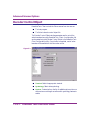
Data Editor Object
PowerNet Twin Client utilizes the data scanning sequence to edit the
data it is scanned.
To make defining the Data Editor Object easier, a PowerNet Scan Editor
has been included with the PowerNet Twin Client Configuration utility.
Figure 5-1
Scan editing is based on the length and pattern of the scanned entry
(determined by Recognition Building Blocks; refer to Table 5-1 on
page 5-6). Once the scanned entry pattern has been recognized, a series
of Operational Building Blocks manipulate the scanned entry. (Refer to
Table 5-2 on page 5-6.)
PowerNet Twin Client User Guide
< 5-5 >
Advanced Scanner Options
The Recognition Building Blocks are illustrated in Table 5-1:
:
Table 5-1
Recognition Building Blocks
Blocks
A: Alpha Character
N: Numeric Character
*: Any Character
=: Must Match Next Character
The Operation Building Blocks are illustrated in Table 5-2:
Table 5-2
Operation Building Blocks
Blocks
X: Delete Character
*: Copy As Is
( ): Substitute
“ ”: Insert
The examples in Table 5-3 illustrate how the Recognition and
Operation Building Blocks manipulate scanned data.
Table 5-3
< 5-6 >
PowerNet TN Scan Editor Examples
Start Value
Size
Recognition
Operation
End Value
PN-1245
7
AA=-NNNN
“F”*******
FPN-1245
5A5567BBAT
10
**********
**********”F”
5A5567BBATF
TGR87
5
AAANN
**(S)**
TGS87
78-RHG
6
NN=-AAA
**X***
78RHG
PowerNet Twin Client User Guide
Data Editor Object
Build Data Editor Object File
Build the Data Editor Object file by completing the following steps.
1.
Verify that the Scanner Tab of the PowerNet Twin Client
Configuration utility is selected.
2.
Press the Edit button next to the Data Editor Object pull-down
list.
3.
Enter the length of the scanned entry in the Size field.
4.
Use the Recognition Building Blocks to construct the pattern of
the scanned entry that will be manipulated in the Recognition
field.
5.
Use the Operational Building Blocks to manipulate the scanned
data entry in the Operation field.
6.
After building the decoder control object file, select Exit from the
File menu.
7.
Press the Yes button to save the decoder control object.
8.
Enter a name for the mapping object file in the File Name field
and press the Save button.
9.
Select the file from the Data Editor Object pull-down list.
Save the PowerNet Twin Client configuration by selecting Save from
the File menu. The selected data editor objects will be loaded the next
time the Falcon terminal is programmed using the PowerNet Twin
Client Configuration utility.
PowerNet Twin Client User Guide
< 5-7 >
Advanced Scanner Options
Decoder Control Object
PowerNet Twin Client controls the Falcon scanner from two sources:
l
The host program.
l
The Falcon’s decoder control object file.
The Decoder Control Object sets the parameters used to control the
active barcodes when using PowerNet Twin Client. A configuration file
can be created using the Decoder Control Object in the PowerNet Twin
Client Configuration utility. Once the file is completed, a set of active
barcodes will be available to the Falcon when online.
Figure 5-2
l
Terminal: Select the appropriate terminal.
l
Symbology: Select active symbology.
l
Options: Determine from the list of available options minimum
and maximum code length as well as which symbology features to
enable.
< 5-8 >
PowerNet Twin Client User Guide
6
Extended Commands
The host application can issue extended commands to the terminal. The
extended command set is a superset of the standard VT100/VT220
escape sequences which allow the following:
l
Enabling and/or disabling barcode decodes.
l
Controlling scanner and/or keyboard input.
l
Setting allowed input character sets.
l
Setting double high, double wide or double high/wide fonts.
l
Control beep duration and frequency.
CHAPTER CONTENTS
Barcode Decoder Control
Extended Commands .................................<7-3>
Input Mode .......................................................<7-4>
Input Validation ................................................<7-5>
Double High/Wide ...........................................<7-6>
Beeper Control..................................................<7-7>
Video Attributes ................................................<7-8>
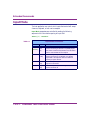
Barcode Decoder Control Extended Commands
Barcode Decoder Control Extended Commands
These commands are sent from the host to change decoder settings
within Falcon 3xx terminals. Refer to online help for the command set.
PowerNet Twin Client User Guide
< 6-3 >
Extended Commands
Input Mode
The host application can control which inputs the terminal will accept.
A scanner, keyboard, or both can be accepted.
Input Mode parameters are controlled by sending the following
sequence to the Falcon before opening an input field:
<ESC>[!1; <mode>z.
Input Mode Parameters
Table 6-1
Mode
Action
0 (de- Scan
fault) and
key
< 6-4 >
Description
Data is initially accepted from either the keyboard or
scanner. Scanning is allowed on a partially keyed
field, which causes the keyed data to be discarded
and the scanned data to be accepted.
1
Scan
or key
Data is initially accepted from either the keyboard or
scanner. Scanning is not allowed on a partially
keyed field. If the operator clears the field then
scanning is again allowed.
2
Scan
only
Data is accepted only from the scanner; the
keyboard is turned off.
3
Key
only
Data is accepted only from the keyboard; the
scanner is turned off.
PowerNet Twin Client User Guide
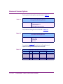
Input Validation
Input Validation
Input validation is used to control the allowed data format for entered
characters. The sequence used for this function is:
<ESC>[!2;<mode>z.
The mode parameter can be one of the following:
:
Table 6-2
Input Validation
Mode
Action
0 (default)
Accept characters between 0x20 and 0x7F.
1
Accept alpha characters only.
2
Accept numeric characters only.
3
Accept alpha and numeric characters.
For example, to allow keyboard input of numeric characters only, the
following sequence would be used:
<ESC>[!1;3z<ESC>[!2;2z
(HEX equivalent: 1B 5B 21 31 3B 33 7A 27 5B 21
32 3B 32 7A)
To reset the terminal back to normal input, the following sequence is
used:
<ESC>[!1;0z<ESC>[!2;0z
(HEX equivalent: 1B 5B 21 31 3B 30 7A 27 5B 21
32 3B 30 7A)
PowerNet Twin Client User Guide
< 6-5 >
Extended Commands
Double High/Wide
This parameter is sent from the host to select double high, double wide
or both double high/wide fonts on the terminal.
The syntax of the command is:
<ESC>[!5;<high>;<wide>z.
Table 6-3
Double High/Wide
Hide
Wide
Action
0
0
Default. Displays characters normally.
1
1
Displays characters in Double Wide Mode.
2
0
Displays characters in Double High Mode.
3
1
Displays characters in both Double High and Double
Wide Mode.
Once a font size has been set, it continues to be in effect until another
font size change is issued or the Falcon is rebooted. To reset to normal
video, use the following sequence to turn off both double high and
double wide:
<ESC>[!5;0;0z
(HEX equivalent: 1B 5B 21 35 3B 30 3B 30 7A)
The font size change command also causes a screen clear simultaneously.
< 6-6 >
PowerNet Twin Client User Guide
Beeper Control
Beeper Control
The beep duration and frequency, and the scan beep duration and
frequency may be set using extended commands. These commands
allow setting the duration of the beeps in milliseconds. The duration on
the Falcon has a granularity of 55 ms because of its PC-based
architecture. This means that any duration is rounded up to the next
multiple of 55 ms. For example, setting a duration of 60 ms actually
causes the beeper to sound for 110 ms.
The frequency is set in hertz. If the frequency is set to zero, the terminal
uses the optimum frequency for the Falcon’s speaker. To control the
beeps, the following escape sequence can be used:
<esc>[!6;1;<Alarm_Dur>;<Alarm_Freq>;<Scan_Dur>
;<Scan_Freq>z
The default settings for the beep are a duration of 150 ms with a
frequency setting of zero (0) while the scan beep defaults to a duration
of 300 ms with a frequency setting of zero (0). The following example
illustrates setting the default values:
<ESC>[!6;1;150;0;300;0z
(HEX equivalent: 1B 5B 21 36 3B 31 3B 31 35 30
3B 30 3B 33 30 30 3B 30 7A)
If desired, the default settings can be changed. For example, to set a beep
of 110 ms at 500 Hz and a scan beep of 220 ms at 1000 Hz, the
following sequence is used:
<ESC>[!6;1;110;500;220;1000z
(HEX equivalent: 1B 5B 21 36 3B 31 3B 31 31 30
3B 35 30 30 3B 32 32 30 3B 31 30 30 30 7A)
PowerNet Twin Client User Guide
< 6-7 >
Extended Commands
Video Attributes
Reverse video and blinking video attributes are supported using the
standard VT-100/220 escape sequences:
Table 6-4
Video Attributes
Blink
<ESC>[5m
(HEX: 1B 5B 35 6D)
Reverse
<ESC>[7m
(HEX: 1B 5B 37 6D)
Blink and Reverse Video must be enabled in advanced VTerm.
< 6-8 >
PowerNet Twin Client User Guide
7
Screen Capture Utility
The Screen Capture utility builds a screen database. The Screen
Formatter utility accesses this database of host application screens and
reformats them to fit on a terminal display screen.
CHAPTER CONTENTS
Start Screen Capture ......................................... <7-3>
Identify Terminal Host...................................... <7-4>
Capture Screens................................................. <7-6>
Start Screen Capture
Start Screen Capture
Before reformatting a terminal application’s screens, a database of the
host’s application screens must be created. The Screen Capture utility
telnets to the host application and saves the individual screens into a
database.
Complete the following steps to start the Screen Capture utility.
1.
Press the Windows Start button.
2.
Select Programs and then select PowerNet TN.
3.
Select Configuration Utility to start the PowerNet Twin Client
Windows Configuration utility.
4.
From the Object Editors menu select Screen Capture.
PowerNet Twin Client User Guide
< 7-3 >
Screen Capture Utility
Identify Terminal Host
After the Screen Capture utility has been started, configure it to connect
to the host application that will be reformatted for the Falcon display.
Before configuring the utility, obtain the following information from the
system administrator:
1.
Host IP Address: The IP address of the system host application.
2.
Host Port: The port used by the host to listen for telnet
connections.
3.
Screen Rows: The number of rows used to display the
application.
4.
Screen Columns: The number of columns used to display the
application.
5.
Emulation: The type of terminal emulation the host server is
expecting.
Complete the following steps to configure the Screen Capture utility:
< 7-4 >
1.
Select Session Settings from the Session menu. Figure 7-1
on page 7-5 illustrates a sample Session Settings window.
2.
Select whether to use a Configuration File. If so, enter the file
directory location. The Browse button can be used to locate the
file if necessary.
3.
Enter the IP address of the host in the Host IP Address field.
4.
Host Port: if necessary, enter the port address for the host. The
default is 23.
PowerNet Twin Client User Guide
Identify Terminal Host
Figure 7-1
5.
If necessary, specify the number of rows displayed on the
terminal’s screen using the Screen Rows field. The default is 24
rows.
If necessary, specify the number of columns displayed on the
terminal’s screen using the Screen Columns field. The default is
80 columns.
Press the OK button when finished configuring the Screen
Capture utility.
PowerNet Twin Client User Guide
< 7-5 >
Screen Capture Utility
Capture Screens
The Screen Capture utility is an enhanced terminal emulator that
captures and records the screens of the host application.
1.
Select Connect from the Session menu.
2.
As each screen of the host application appears, take a snapshot of
each screen that requires formatting.
Capture snapshots by performing one of these three steps:
w Press <CTL><T>.
w Select Snapshot from Session menu.
w Press the Snapshot button on the toolbar (the Camera icon).
It is best to take a screen snapshot after data has been entered into all of the
fields on the screen. Reviewing a screen complete with data will make it
easier to format.
< 7-6 >
3.
Once the snapshots of the host application’s screens have been
taken, select Save from the File menu.
4.
Enter the name of the screen database in the File Name field and
press the Save button.
5.
Select Exit from the File menu to close the Screen Capture utility.
PowerNet Twin Client User Guide
8
Screen Formatter Utility
The Screen Formatter reformats the host application screens to meet the
display requirements of a Falcon terminal.
CHAPTER CONTENTS
Starting the Screen Formatter ........................... <8-3>
Configure Screen Formatter
Screen Formatter Concepts ............................... <8-4>
Screen Elements
Screen Formatter Environment
Using PowerNet Twin Client
Screen Formatter ....................................... <8-7>
Specify Screen Identifier
Mark Screen Elements
Build Terminal Screen
After Reformatting
Starting the Screen Formatter
Starting the Screen Formatter
Complete the following steps to start the Screen Formatter utility.
1.
Press the Windows Start button.
2.
Select Programs and then select PowerNet TN.
3.
Select Screen Formatter under the Tools Menu to start the
PowerNet Twin Client Windows Configuration utility.
w After starting the Screen Formatter utility, open the desired
screen database.
4.
Select Open from the File menu.
5.
Select the screen database that contains the snapshots that will be
reformatted and press the Open button.
The first screen snapshot will be displayed in the Formatter
window.
Configure Screen Formatter
Before formatting the host application screens, the appropriate
configuration settings must be completed.
1.
Select Setup from the Tools menu.
2.
Select the type of emulation needed to use with the host
application from the Emulation pull-down list.
3.
Select the Falcon Type from the list of Terminal Screen types.
4.
If necessary, adjust the rows and columns to match the host
application using the Rows and Columns fields.
5.
Press the OK button when complete.
PowerNet Twin Client User Guide
< 8-3 >
Screen Formatter Utility
Screen Formatting Concepts
Formatting the host application’s display to meet the needs of the data
terminal involves manipulating four screen elements: Screen
Identification Tag, Display Text, Display Fields, and Input Fields.
Once elements have been identified, drag and drop or copy and paste to
the terminal screen.
Figure 8-1 The Four Elements of Screen Formatting
Formatter Window
Terminal Screen
Screen Identification Tag
(Red Text)
Display Text
(Black Text)
Display Field
(Green Text)
Input Field
(Blue Bars)
< 8-4 >
PowerNet Twin Client User Guide
Screen Formatting Concepts
Screen Elements
The screen elements are the tools used to reformat the host application’s
original screen for the terminal. The following four screen elements are
needed to completely reconstruct the host application’s screen.
Screen Identification Tag
A Screen Identification Tag must be assigned to each host application
screen snapshot. This identification tag serves as a link between the host
application screen and the reformatted screen displayed on the terminal.
This identification tag also enables splitting large host application
displays into multiple terminal display pages. For example, if a host
application screen contains more rows of screen elements than can be
properly displayed on a Falcon terminal, it may be divided into multiple
display pages.
Display Text
The Display text element is descriptive (or directive) text that appears
on the terminal display. Display text is statically defined.
Display Fields
Display fields are used to display information from the host
application server. For example, a Display field is used to display an
item description that is retrieved after a user enters a part number.
Input Fields
Input fields are the only screen element that accept data entry from the
user. Input fields also can be used as Display fields
This is beneficial when the host application server is displaying data that
a user must verify and/or update. For example, an ordered quantity may
be displayed, accepted, and/or changed using an Input field.
PowerNet Twin Client User Guide
< 8-5 >
Screen Formatter Utility
Screen Formatter Environment
The Screen Formatter supports the use of standard Windows techniques
to reformat the application screen for the terminal. As illustrated in
Figure 8-1 on page 8-4, the Screen Formatter has two windows: the
Formatter Window and the Terminal Screen.
Formatter Window
The screen snapshots that were saved earlier are displayed in the
Formatter window. Identify the screen elements in the Formatter
window and drag them to the desired location in the Terminal screen.
There are a series of navigation controls to scroll through the screen
snapshots contained in the current database.
When scrolling through these screen snapshots, formatted screens from
the Terminal screen will be displayed.
Terminal Screen
Formatted screens are built using the space contained in the Terminal
screen. Multiple Terminal screens can be useful when working with a
single screen snapshot. Press the New button on the Terminal screen to
create an additional terminal display page for the current host screen
snapshot.
< 8-6 >
PowerNet Twin Client User Guide
Using PowerNet Twin Client Screen Formatter
Using PowerNet Twin Client Screen Formatter
Figure 8-2 illustrates a screen that has just been loaded in the Screen
Formatter. Note the following elements:
l
The numbers below the PartNo Display Text and to the right of
the Price Display Text are Input Fields. This field does not
automatically appear as an Input Field because it was not the
Input Field when the screen shot was taken (this screen element
can be marked as an Input Field).
l
The 20lb Super Green Law and 994 screen elements are
both Display Fields. These screen elements can also be marked.
l
The vertical bars automatically identify the Cost Input Field.
The Cost Input Field was highlighted when the screen snapshot
was taken.
The rest of the screen elements displayed are Display Text elements.
Figure 8-2 Mark an Input Field Screen Element
PowerNet Twin Client User Guide
< 8-7 >
Screen Formatter Utility
Specify Screen Identifier
Specify a Screen Identifier for each screen snapshot. This is critical in
maintaining the link between the host application and reformatted
screens.
Complete the following steps to specify the screen identifier:
1.
Identify specific text on the screen snapshot that is unique to this
screen.
w Figure 8-3 illustrates the text [INV MASTER FILE],
which is unique to this screen snapshot.
Figure 8-3 Screen Formatter
2.
3.
Highlight the unique text.
Right-click on the highlighted text and select Add Ident. Figure
8-4 on page 8-9 illustrates this window.
After Add Ident is selected, the highlighted text will turn red. Note that
only one Screen Identifier is needed per screen snapshot
< 8-8 >
PowerNet Twin Client User Guide
Using PowerNet Twin Client Screen Formatter
Figure 8-4 Converting Unique Screen Text into a Screen Identifier
Mark Screen Elements
After specifying the Screen Identifier, mark the screen elements
contained in the snapshot.
Mark Input Fields
The numbers below the PartNo Display Text, the numbers to the right
of the Price Display Text, and the vertical bars to the right of the Cost
Display Text are all input fields. Since the Cost Input Field has
automatically been defined, only mark the input field below the PartNo
Display Text.
1.
Highlight the number below the PartNo Display Text.
w Highlight beyond the end of the number to accept data entry
greater than the displayed length. Avoid highlighting any
length greater than the width of the Falcon terminal display.
PowerNet Twin Client User Guide
< 8-9 >
Screen Formatter Utility
2.
Right-click on the highlighted text and select Add Input Field.
w After selecting the Add Input Field, the highlighted text will
be replaced with blue vertical bars (these will be marked as
light blue since this input field has not been placed on the
terminal screen).
3.
Highlight the number to the right of the Price Display Text.
w Highlight beyond the end of the number to accept data entry
greater than the displayed length.
4.
Right-click on the highlighted text and select Add Input Field.
After selecting the Add Input Field, the highlighted text will be
replaced with blue vertical bars.
Mark Display Fields
The numbers below the Description Display Text and the numbers to
the right of the OnHand Display Text are both Display Fields. The
process for marking Display Fields is the same as marking Input
Fields, except that Add Display Fields is selected.
1.
Highlight the text below the Description Display Text.
w Highlight beyond the end of the number to display data
longer than the currently selected value.
w Avoid highlighting any length greater than the width of the
Falcon terminal display. Figure 8-5 on page 8-11 illustrates
this window.
2.
Right-click on the highlighted text and select Add Display Field.
w After selecting the Add Display Field, the highlighted text
will be colored green. If spaces were included in the
highlighted text, green dots will replace those spaces.
3.
Highlight the number to the right of the OnHand Display Text.
w Highlight beyond the end of the number to display data
longer than the currently displayed value.
w Avoid highlighting any length greater than the width of the
Falcon terminal display.
< 8-10 >
PowerNet Twin Client User Guide
Using PowerNet Twin Client Screen Formatter
Figure 8-5 Drag Screen Elements from Formatter Window to Terminal Screen
4.
Right-click on the highlighted text and select Add Display Field.
w After selecting the Add Display Field, the highlighted text
will be colored green. If spaces were included in the
highlighted text, green dots will replace those spaces.
Display Text
Unlike the other Screen Elements, it is not necessary to explicitly
mark the location of Display Text. Either type new display text directly
Display Text from the Formatter window.
PowerNet Twin Client User Guide
< 8-11 >
Screen Formatter Utility
Build Terminal Screen
Once the screen identifier has been set, mark the Input and Display
Fields.
Complete the following steps to build the reformatted screen in the
Terminal screen.
< 8-12 >
1.
Position the cursor in the middle of the top row of the Terminal
Screen and type INVENTORY.
w This is a good example of defining different Display Text on
the formatted screen. This is especially useful if the length of
the Display Text must be shortened.
2.
Highlight the PartNo Display Text in the Formatter window.
3.
Click and hold the highlighted text. Drag the text to the
beginning of the second row of the Terminal Screen.
4.
Highlight the Input Field below the PartNo Display Text.
w Click and hold the highlighted Input Field. Drag the field to
the beginning of the third row of the Terminal Screen.
5.
Press the New button on the Terminal Screen to create a second
terminal screen for the current screen snapshot.
w After the user enters a part number in the PartNo Input Field,
the second terminal screen will automatically be displayed. By
using multiple terminal screens, it is easier to reformat host
applications that have numerous screen elements.
6.
Highlight the Description Display Text in the Formatter
window.
7.
Click and hold the highlighted text. Drag the text to the
beginning of the first row of the Terminal Screen.
8.
Highlight the Input Field below the Description Display Text.
9.
Click and hold the highlighted Input Field. Drag the field to the
beginning of the second row of the Terminal Screen.
PowerNet Twin Client User Guide
Using PowerNet Twin Client Screen Formatter
10.
Highlight the row that contains both the OnHand Display Text
and Display Field.
w An entire line in the Formatter window can be selected, even
if the line contains more than one type of screen element.
11.
Click and hold the highlighted selection. Drag the selection to the
fourth row of the Terminal Screen.
12.
Highlight the row that contains both the Price Display Text and
Input Field.
13.
Click and hold the highlighted selection. Drag the selection to the
fifth row of the Terminal Screen. Figure 8-6 illustrates the
Terminal screen.
Figure 8-6 Drag Screen Elements to the Second Terminal Screen
14.
Highlight the row that contains both the Cost Display Text and
Input Field.
PowerNet Twin Client User Guide
< 8-13 >
Screen Formatter Utility
15.
Click and hold the highlighted selection. Drag the selection to the
sixth row of the Terminal Screen.
The screen snapshot illustrated in Figure 8-5 on page 8-11 has been
reformatted into two terminal display pages.
Additional screen snapshots can be reformatted.
w Press the Next (>) button at the bottom of the Formatter
window to display the next screen snapshot.
w Repeat the above steps until all of the screen snapshots
contained in the current screen database have been
reformatted.
After Reformatting
After reformatting all of the necessary screens in the screen database,
complete the following steps:
1.
Verify that the Display tab of the PowerNet Twin Client
Configuration utility is selected.
2.
Press the Edit button next to the Mapping Object pull-down list.
3.
Enter a name for the Mapping Object file in the File Name field
and press the Open button.
4.
Define all of the necessary character mappings.
5.
When finished defining the character mappings, select Exit from
the File menu.
6.
Press the Yes button to save the defined character mappings.
7.
Select the file from the Mapping Object pull-down list.
Save the PowerNet Twin Client configuration by selecting Save from
the File menu. The selected display mapping objects will be loaded the
next time the Falcon terminal is programmed using the PowerNet Twin
Client Configuration utility.
< 8-14 >
PowerNet Twin Client User Guide
APPENDIX A:
Keyboard Maps for the
PSC Falcon 315
APPENDIX CONTENTS
Model VT ......................................................... <A-iii>
Models 3270/5250 ........................................... <A-iv>
Model VT
Model VT
Model VT
Table A-1
Base
Alpha
FN 1
FN 2
Caps
Ctrl
Alt
Esc
Up
Down
Left
Right
1
2
3
4
5
6
7
8
9
0
.
Space
BkSp
+
=
#
$
,
%
:
\
*
?
Intl
Delete
Esc
a
b
c
d
k
l
m
h
i
j
e
f
g
o
n
p
Space
BkSp
q
r
s
t
u
v
w
x
y
z
Esc
Esc
Top
Bottom
Home
Esc
View Up
View Down
View Left
View Right
Esc
Dark
Light
Space
BkSp
‘
&
~
[
_
“
;
/
]
^
Esc
A
B
C
D
K
L
M
H
I
J
E
F
G
O
N
P
Space
BkSp
Q
R
S
T
U
V
W
X
Y
Z
Space
BkSp
Space
BkSp
Delete
Delete
Delete
Delete
Delete
F1
F2
F3
F4
F5
F6
F7
F8
F9
F10
Space
BkSp
(
@
|
{
<
)
!
‘
}
>
Swap
Delete
F11
F12
F13
F14
F15
F16
F17
F18
F19
F20
PowerNet Twin Client User’s Guide
< A-iii >
Models 3270/5250
Table A-2
Models 3270/5250
Base
Alpha
FN 1
FN 2
Caps
Ctrl
Alt
Esc
Up
Down
Left
Right
1
2
Esc
a
b
c
d
k
l
Esc
Esc
Top
Bottom
Home
Esc
View Up
View Down
View Left
View Right
Esc
F1
F2
Esc
A
B
C
D
K
L
3
m
F3
4
5
6
7
8
9
0
.
Space
BkSp
+
=
#
$
,
%
:
\
*
?
Enter
h
i
j
e
f
g
o
n
p
Space
BkSp
q
r
s
t
u
v
w
x
y
z
Enter
F4
F5
F6
F7
F8
F9
F10
Space
BkSp
(
@
|
{
<
)
!
‘
}
>
Enter
Dark
Light
Space
BkSp
‘
&
~
[
_
“
;
/
]
^
Enter
F11
F12
FieldNum.Ovr
1
M
F13
Roll Down
1
H
I
J
E
F
G
O
N
P
Space
BkSp
Q
R
S
T
U
V
W
X
Y
Z
Enter
F14
F15
F16
F17
F18
F19
F20
Reset
SysReq
Space
BkSp
Space
BkSp
PA1
1
PA2
PA3
New Line
Null End
Field Mark
Roll Up
Field+
Refresh
Stat
Dup
Redraw
Dev.Cncl
Enter
2
Intl
Swap
Delete Delete Delete Delete Delete
Delete
1. PA1, PA2, and PA3 are only in 3270 mode.
2. Alt+Enter is Field Exit in 3270 and EOF in 5250.
< A-iv >
Alpha+Alt Fn1+Alt
PowerNet Twin Client User’s Guide
EOF/FldEx
Delete
Help
Enter
Enter
APPENDIX B:
Keyboard Maps for the
PSC Falcon 325
APPENDIX CONTENTS
Model VT ......................................................... <B-iii>
Models 3270/5250 ........................................... <B-iv>
Model VT
Model VT
Model VT
Table B-1
Base
Cap
F1
F2
F3
F4
F5
0
1
2
3
4
5
6
7
8
9
Space
Esc
BkSp
Up
Down
Left
Right
a
b
c
d
e
f
g
h
i
j
k
F1
F2
F3
F4
F5
0
1
2
3
4
5
6
7
8
9
Space
Esc
BkSp
Up
Down
Left
Right
A
B
C
D
E
F
G
H
I
J
K
Ctrl
0
1
2
3
4
5
6
7
8
9
Space
Esc
BkSp
View Up
View Down
View Left
View Right
Alt
Fn
Intl
F11
F12
F13
F14
F15
F6
F7
F8
F9
F10
:
/
@
‘
$
!
^
‘
?
~
Space
Esc
BkSp
F11
F12
F13
F14
F15
Space
Esc
BkSp
Info
\
*
.
+
|
_
&
,
=
<
Space
Esc
BkSp
Roll Up
Roll Down
F16
F17
F18
F19
F20
Home
Info
table continues on next page
PowerNet Twin Client User’s Guide
< B-iii >
Table B-1
(Continued)
< B-iv >
Model VT
Base
Cap
l
m
n
o
p
q
r
s
t
u
v
w
x
y
z
L
M
N
O
P
Q
R
S
T
U
V
W
X
Y
Z
Ctrl
Alt
Fn
Intl
>
(
)
#
;
[
]
End Pos.
PowerNet Twin Client User’s Guide
Insert
%
“
{
}
End Pos.
Models 3270/5250
Models 3270/5250
Table B-2
Models 3270/5250
Base
Caps
F1
F2
F3
F4
F5
0
1
2
3
4
5
6
7
8
9
Space
Esc
BkSp
Up
Down
Left
Righ
a
b
c
d
e
f
g
h
i
j
k
F1
F2
F3
F4
F5
0
1
2
3
4
5
6
7
8
9
Space
Esc
BkSp
Up
Down
Left
Right
A
B
C
D
E
F
G
H
I
J
K
Ctrl
F24
0
1
2
3
4
5
6
7
8
9
Space
Esc
BkSp
View Up
View Down
View Left
View Right
Alt
Fn
Intl
F11
F12
F13
F14
F15
F6
F7
F8
F9
F10
:
/
@
‘
$
!
^
‘
?
~
Space
Esc
BkSp
F11
F12
F13
F14
F15
Space
Esc
BkSp
Clear
Info
\
*
.
+
|
_
&
,
=
<
Space
Esc
BkSp
Roll Up
Roll Down
F16
F17
F18
F19
F20
F21
F22
F23
Info
M1
M2
table continues on next page
PowerNet Twin Client User’s Guide
< B-v >
Table B-2
Models 3270/5250
Base
l
m
n
o
p
q
r
s
t
u
v
w
x
y
z
< B-vi >
Caps
Ctrl
Alt
Fn
Intl
L
>
M3
M
(
Home
N
)
Field O
#
Field +
P
;
ErEOF
Q
[
ErlNP
R
]
Reset
S
SysReq
T
Insert
Clear
U
%
Attention
V
“
End Pos.
W
{
Help
X
}
Field Exit
Y
Z
PF24 Mapped to same location is Info key, which is
info I, so only Info key works.
PowerNet Twin Client User’s Guide
APPENDIX C:
Keyboard Maps for the
PSC Falcon 335
APPENDIX CONTENTS
Model VT ......................................................... <C-iii>
Models 3270/5250 ........................................... <C-iv>
Model VT
Model VT
Model VT
Table C-1
Base
Cap
F1
F2
F3
F4
F5
0
1
2
3
4
5
6
7
8
9
Space
Esc
a
b
c
d
e
f
g
h
i
j
k
l
m
n
o
p
F1
F2
F3
F4
F5
0
1
2
3
4
5
6
7
8
9
Space
Esc
A
B
C
D
E
F
G
H
I
J
K
L
M
N
O
P
Ctrl
0
1
2
Roll down
4
5
6
7
8
Roll Up
Space
Esc
Alt
Fn
F11
F12
F13
F14
F15
F6
F7
F8
F9
F10
Tab
End
Down
PgDn
Left
View Key
Right
Home
Up
PgUp
BkSp
Del
@
#
‘
>
/
=
\
!
+
$
%
~
<
‘
|
Field Mark
View Down
View Left
View Right
View Up
9
Space
Esc
F16
F17
F18
F19
F20
Home
Info
table continues on next page
PowerNet Twin Client User’s Guide
< C-iii >
Table C-1
(Continued)
Model VT
Base
q
r
s
t
u
v
w
x
y
z
< C-iv >
Cap
Ctrl
Alt
Q
R
S
T
Insert
U
V
W
X
End Pos.
Y
Z
Intl maps to the same keys as Alt
PowerNet Twin Client User’s Guide
Fn
?
_
:
;
%
&
*
“
.
,
Models 3270/5250
Models 3270/5250
Table C-2
Models 3270/5250
Base
Caps
F1
F2
F3
F4
F5
0
1
2
3
4
5
6
7
8
9
Space
Esc
a
b
c
d
e
f
g
h
i
j
k
l
m
n
o
p
F1
F2
F3
F4
F5
0
1
2
3
4
5
6
7
8
9
Space
Esc
A
B
C
D
E
F
G
H
I
J
K
L
M
N
O
P
Ctrl
0
1
2
Roll down
4
5
6
7
8
Roll Up
Space
Esc
Alt
Fn
F11
F12
F13
F14
F15
F6
F7
F8
F9
F10
Tab
End
Down
PgDn
Left
View Key
Right
Home
Up
PgUp
BkSp
Del
@
#
‘
>
/
=
\
!
+
$
%
~
<
‘
|
Field Mark
View Down
View Left
View Right
View Up
Space
Esc
F16
F17
F18
F19
F20
F21
F22
F23
Info
M1
M2
M3
Home
Field Field +
ErEOF
table continues on next page
PowerNet Twin Client User’s Guide
< C-v >
Table C-2
Models 3270/5250
Base
Caps
Ctrl
q
r
s
t
u
v
w
x
y
z
Alt
Fn
Q
ERINP
?
R
Reset
_
S
SysReq
:
T
Insert
Clear
;
U
Attention
%
V
End Pos
&
W
Help
*
X
Field Exit
“
Y
.
Z
,
Intl maps to same the same keys as Alt
.PF24 Mapped to same location as Info key, which is Alt I, so only Info
key works.
< C-vi >
PowerNet Twin Client User’s Guide
APPENDIX D:
Keyboard Maps
for the LXE
APPENDIX CONTENTS
Model VT ..........................................................<D-iii>
Models 3270/5250 ............................................<D-iv>
Model VT
Model VT
Model VT
Table D-1
Base
Shift
F1
F2
F3
F4
F5
F6
F7
F8
F9
F10
Up
Down
Left
Right
0
1
2
3
4
5
6
7
8
9
.
Back Space
Space
Esc
a
b
c
d
e
F11
F12
F13
F14
F15
F16
F17
F18
F19
F20
Up
Down
Left
Right
Ctrl
Alt
2nd
Back Light
View Up
View Down
View Left
View Right
Roll Up
Roll Down
Darken
Lighten
Down
Roll Down
ErEOF
<
[
]
=
Left
Right
ErEOF
Up
Delete
Space
Esc
A
B
C
D
E
Space
Esc
Ctrl a
Ctrl b
Ctrl c
Ctrl c
Ctrl e
Space
Esc
{
}
/
+
Delete
Insert
Space
Esc
|
~
:
#
table continues on next page
PowerNet Twin Client User’s Guide
< D-iii >
Table D-1
(Continued)
< D-iv >
Model VT
Base
Shift
Ctrl
f
g
h
i
j
k
l
m
n
o
p
q
r
s
T
u
v
w
x
y
z
F
G
H
I
J
K
L
M
N
O
P‘
Q
R
S
t
U
V
W
X
Y
Z
Ctrl f
Ctrl g
Ctrl h
Ctrl i
Ctrl j
Ctrl k
Ctrl l
Ctrl m
Ctrl n
Ctrl o
Ctrl p
Ctrl q
Ctrl r
Ctrl s
Ctrl t
Ctrl u
Ctrl v
Ctrl w
Ctrl x
Ctrl y
Ctrl z
PowerNet Twin Client User’s Guide
Alt
2nd
;
“
‘
*
,
.
?
_
‘
(
)
!
$
\
%
&
@
^
Models 3270/5250
Models 3270/5250
Table D-2
Models 3270/5250
Base
Shift
Ctrl
F1
F2
F3
F4
F5
F6
F7
F8
F9
F10
Up
Down
Left
Right
0
1
2
3
4
5
6
7
8
9
.
Back Space
Space
Esc
a
b
c
d
e
F11
F12
F13
F14
F15
F16
F17
F18
F19
F20
Up
Down
Left
Right
F21
F22
F23
F24
Alt
Back Light
View Up
View Down
View Left
View Right
Roll Up
Roll Down
Darken
Lighten
PA1
PA2
PA3
Down
Left
Right
ErEOF
Up
Delete
Space
Esc
A
B
C
D
E
2nd
Space
Esc
Ctrl a
Ctrl b
Ctrl c
Ctrl c
Ctrl e
Space
Esc
Attention
Bottom
Clear
Redraw
Field Exit
Home
ErEOF
<
[
]
>
=
{
}
/
+
Delete
Insert
Space
Esc
|
~
:
#
table continues on next page
PowerNet Twin Client User’s Guide
< D-v >
Table D-2
< D-vi >
Models 3270/5250
Base
Shift
Ctrl
Alt
2nd
f
g
h
i
j
k
l
m
n
o
p
q
r
s
T
u
v
w
x
y
z
F
G
H
I
J
K
L
M
N
O
P‘
Q
R
S
t
U
V
W
X
Y
Z
Ctrl f
Ctrl g
Ctrl h
Ctrl i
Ctrl j
Ctrl k
Ctrl l
Ctrl m
Ctrl n
Ctrl o
Ctrl p
Ctrl q
Ctrl r
Ctrl s
Ctrl t
Ctrl u
Ctrl v
Ctrl w
Ctrl x
Ctrl y
Ctrl z
Field Mark
;
“
‘
*
,
.
?
_
‘
(
)
!
$
\
%
&
PowerNet Twin Client User’s Guide
Help
Info
Local Exit
Field New Line
Field +
Reset
Sys Req
Top
Dup
Refresh
@
Null End
Back Tab
^
A
Blink Mask
Advanced button
Keyboard Tab 2-10
Advanced VTERM Display
Display Tab 2-18
Alarm Tab 2-27
Allow Multiple 2-30
Duration 2-29
Frequency 2-29
Mode 2-27
Scan Duration 2-29
Scan Frequency 2-29
Volume 2-29
Volume values
Alarm Tab 2-29
AlarmMode
Alarm Tab 2-27
Algorithm 2-26
Allow Multiple
Alarm Tab 2-30
Answerback 2-33
AP Polling Options Group 2-25
Algorithm 2-26
Max 2-26
Primary/Min 2-26
Attribute Mask
Display Tab 2-18
Authorization code
entering 1-10
Auto Send Key
Keyboard Tab 2-9
B
Backlight 2-25
Binary 128
Scanner Tab 2-21
Display Tab 2-19
Build
data editor object file 5-7
C
capture screens 7-6
Case Configuration
Keyboard Tab 2-9
Values 2-9
Commands
Barcode Decoder Control 6-3
Beeper Control 6-7
Double High/Wide 6-6
DoubleHigh/Wide
Values 6-6
Input Mode 6-4
Input Mode Parameters 6-4
Input Validation 6-5
Video Attributes 6-8
Values 6-8
Communications Port 1-4
Configuration Menu 1-7
Demo mode 1-11
Edit Authorization 1-10
Edit Host List 1-9
Edit IP 1-8
required settings 1-7
Sample Authorization Screen 1-10
Sample Host List 1-9
Sample IP address 1-8
Start Screen 1-7
Configuration utility 2-1, 2-7, 2-27
Alarm Tab 2-27
Volume 2-29
Volume values 2-29
Display Tab 2-11
PowerNet Twin Client User Guide
< Index-i >
Quadrant Mode 2-11
Screen 2-11
grayed out fields 2-7
Host Servers 2-4
Keyboard Tab 2-8
Advanced button 2-10
Auto Send Key 2-9
Case Conversion 2-9
Case Conversion Values 2-9
End Key 2-8
Key Click 2-9
Macro Object 2-10
Screen 2-3, 2-8
Log Levels Tab 2-22
Misc Tab 2-32
New-Environ setting 2-6
screen 2-6
on Falcon 1-7
Polling/Timers Tab 2-23
Printer Tab 2-30
Scanner Tab 2-19
Setting Emulation 2-4
Setting Host Servers 2-4
starting 2-3
Terminal Emulation 2-4
values 2-4
Configuring
Screen Formatter utility 8-3
Cursor
Display Tab 2-15
D
Data Editor Object 5-5
build 5-7
Operation Building Blocks 5-6
Recognition Building Blocks 5-6
Scanner Tab 2-21
< Index- ii >
Data Mapping Object
Scanner Tab 2-21
Data Stream Group 2-32
Decoder Control Object 5-8
Scanner Tab 2-22
Demo mode 1-11
Destination
Display Tab 2-16
Dialog
Log Levels Tab 2-22
Dialog Objects Group
Display Tab 2-15
Display
Log Levels Tab 2-22
Display Fields 8-5
Display Tab
Advanced VTERM Display 2-18
Attribute Mask 2-18
Blink Mask 2-19
Configuration utility 2-11
Cursor 2-15
Destination 2-16
Dialog Objects Group 2-15
Double High 2-17
Double Wide 2-17
Field Mask 2-18
Formatter
Objects Group 2-15
Language 2-14
Lock Column 2-13
Lock Column Values 2-13
Lock Row 2-12
Lock Row Values 2-12
Mapping Object 2-15
Move Blank 2-17
Quadrant Mode 2-11
Values 2-12
Relocation Options Group 2-16
PowerNet Twin Client User Guide
Reverse Video 2-17
Row Count 2-17
Screen 2-11
Scroll Mode 2-13
Source 2-16
Wait Message 2-17
Display Tab 2-18
Formatter
Log Levels Tab 2-22
Formatter Objects Group
Display Tab 2-15
Formatter Window 8-6
Frequency
Alarm Tab 2-29
Display Text 8-5, 8-11
Double High
Display Tab 2-17
Double Wide
Display Tab 2-17
Duration
Alarm Tab 2-29
H
Host Servers
setting 2-4
I
E
Edit host list 1-9
Edit IP 1-8
Elements
Screen Formatter utility 8-4
Emulation
setting 2-4
Values 2-4
Emulator
Starting 1-12
End Key
K
Keyboard Tab 2-8
Environment 8-6
error, recoverable 1-11
Extended Command Set 2-32
F
Falcon
Loading 2-34
Programming 2-34
safe boot 1-5, 1-6, 1-12
Field Mask
Identification Tag 8-5
Init Object 2-31
Input Fields 8-5
Input Validation
Values 6-5
Installation 1-3
Key 1-3
setup .exe file 1-3
Key
Installation 1-3
Key Click
Keyboard Tab 2-9
Keyboard Maps A-i, B-i, D-i
Falcon315 A-i
Falcon325 B-i
LXE D-i
Keyboard maps
Falcon315
Model VT A-iii
PowerNet Twin Client User Guide
< Index-iii >
Models 3270/5250 A-iv
Falcon325
Model VT B-iii
Models 3270/5250 B-v
Falcon335
Model VT C-iii
Models 3270/5250 C-v
LXE
Model VT D-iii
Models 3270/5250 D-v
Keyboard MapsKeyboard Maps
Falcon335 C-i
Keyboard Tab
Advanced
screen 2-10
Advanced button 2-10
Case Configuration 2-9
Values 2-9
configuration utility 2-8
Key Click 2-9
Macro Object 2-10, 3-3
Mapping Object 2-10, 3-5
L
Language
Display Tab 2-14
Loading Falcon 2-34
Loading New Configuration 2-34
Lock Column
Display Tab 2-13
Values 2-13
Lock Row
Display Tab 2-12
Log Levels Tab
Configuration utility 2-22
Dialog 2-22
< Index- iv >
Display 2-22
Formatter 2-22
General 2-22
M
Macro Object
Keyboard Tab 2-10
Macros, Keyboard 3-3
Build 3-3
Falcon Key Codes 3-4, A-iii, B-iii, C-iii,
D-iii
Mapping Object
build file 4-4
building 4-4
character sets 4-3
Data 5-3
display 4-3
Display Tab 2-15
Keyboard 3-5
Keyboard Tab 2-10
Mapping Object, Data
Define 5-3
Mapping Object, Keyboard
Define 3-7
Max 2-26
Misc Tab 2-32
Mode
Alarm Tab 2-27
Move Blank
Display Tab 2-17
N
New Configuration
loading 2-34
New-Environ setting
screen 2-6
PowerNet Twin Client User Guide
O
R
Operation Building Blocks 5-6
Options
Communications Port 1-4
Radio Type 1-4
P
Polling/Timers Tab
Algorithm 2-26
AP Polling Options Group 2-25
Backlight 2-25
Configuration utility 2-23
Max 2-26
Power 2-25
Primary/Min 2-26
Radio 2-24
Timers Options Group 2-24
Power 2-25
Primary/Min 2-26
Printer Options Group
Init Object 2-31
Printer Type 2-31
Printer Type Values 2-31
Printer Tab
Configuration utility 2-30
Init Object 2-31
PrinterType 2-31
PrinterType Values 2-31
Printer Type 2-31
Values 2-31
Programming Falcon 2-34
Q
Quadrant Mode
Display Tab 2-11
Radio 2-24
Type 1-4
rebooting Falcon 1-5, 1-6, 1-12
Recognition Building Blocks 5-6
recoverable error 1-11
Relocation Options Group
Destination 2-16
Display Tab 2-16
Move Blank 2-17
Row Count 2-17
Source 2-16
Reverse Video
Display Tab 2-17
Row Count
Display Tab 2-17
Running emulator 1-12
S
safe boot 1-5, 1-6, 1-12
Scan Ahead
Scanner Tab 2-19
Scan Duration 2-29
Scan Frequency
Alarm Tab 2-29
Scanner Tab 2-19
Binary 128 2-21
Data Editor Object 2-21, 5-5
Data Mapping Object 2-21, 5-3
Decoder Control Object 2-22, 5-8
Scan Ahead 2-19
Send Key 2-19
Stripping 2-20
Truncation 2-19
Screen capture utility
capture screens 7-6
PowerNet Twin Client User Guide
< Index-v >
session settings screen 7-5
starting 7-3
target terminal 7-4
Screen Elements 8-5
Screen Formatter utility
after reformatting 8-14
Configuring 8-3
Display Tab 2-16
Starting
Configuration utility 2-3
Emulator 1-12
PowerNet Twin Client 1-6
Stripping
Scanner Tab 2-20
Elements
Display Text 8-11
elements 8-4
dragging 8-11, 8-13
marking 8-7, 8-9
marking display fields 8-10
marking input fields 8-9
elements of 8-4
Environment 8-6
Formatter Window 8-6
Terminal Screen 8-6
Screen Elements 8-5
Display Fields 8-5
Display Text 8-5
Identification Tag 8-5
Input Fields 8-5
Screen Identifier 8-8
starting 8-3
Terminal Screen
Building 8-12
Using 8-7
Screen Identifier 8-8
Scroll Mode
Display Tab 2-13
Send Key
Scanner Tab 2-19
Servers
screen 2-5
setup.exe file 1-3
Source
< Index- vi >
T
Target terminal
screen capture utility 7-4
Terminal Emulation
setting 2-4
supported vii
values 2-4
Terminal Screen 8-6
Building 8-12
viewport panning 1-13
Terminal scripting
Emulation
types 2-6
Timers Options Group
Backlight 2-25
Polling/Timers Tab 2-24
Power 2-25
Radio 2-24
Truncation
Scanner Tab 2-19
U
Using
Screen Formatter utility 8-7
V
Values
PowerNet Twin Client User Guide
Case Configuration 2-9
Double High/Wide 6-6
Emulation 2-4
Input Mode Parameters 6-4
Input Validation 6-5
Lock Row 2-12
Printer Type 2-31
Quadrant Mode 2-12
Video Attributes 6-8
Viewport panning 1-13
Volume
Alarm Tab 2-29
Values 2-29
W
Wait Message
Display Tab 2-17
PowerNet Twin Client User Guide
< Index-vii >
Asia Pacific
PSC Hong Kong
Hong Kong
Telephone: [852]-2-584-6210
Telefax: [852]-2-521-0291
Italy
PSC S.r.l.
Vimercate (MI), Italy
Telephone: [39] (0) 39/62903.1
Telefax: [39] (0) 39/6859496
Australia
PSC Asia Pacific Pty Ltd.
North Ryde, Australia
Telephone: [61]0(2)9878 8999
Telefax: [61]0(2)9878 8688
Japan
PSC Japan K.K.
Shinagawa-ku, Tokyo, Japan
Telephone: [81] (0)3 3491 6761
Telefax: [81] (0)3 3491 6656
France
PSC Sarl
LES ULIS Cedex, France
Telephone: [33] .01.64.86.71.00
Telefax: [33] .01.64.46.72.44
Latin America
PSC S.A., INC.
Miami, Florida, USA
Telephone: (305) 539-0111
Telefax: (305) 539-0206
Germany
PSC GmbH
Darmstadt, Germany
Telephone: [49] (0) 61 51/93 58 0
Telefax: [49] (0) 61 51/93 58 58
United Kingdom
PSC Bar Code Ltd.
Watford, England
Telephone: [44] (0)1923 809500
Telefax: [44] (0) 1923 809 505
PSC Europe, S.A.
La Cell Saint Cloud, France
Telephone: [33] .01.30.78.44.80
Telefax: [33] .01.39.18.53.94
Corporate Headquarters
675 Basket Road
Webster, NY 14580-9787
Telephone: (716) 265-1600
Toll Free: (800) 828-6489
Telefax: (716) 265-6400
© 2000 PSC Inc.
PSC Scanning, Inc.
959 Terry Street
Eugene, OR 97402-9150
Telephone: (541) 683-5700
Toll Free: (800) 547-2507
Telefax: (541) 686-1702
00-649-00
00-649-00
PSC Millrace
1800 Millrace Drive
Eugene, OR 97403
Telephone: (541) 344-1189
Toll Free: (800) 929-7899
Telefax: (541) 344-1399
www.pscnet.com