1
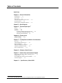
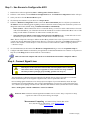
USER’S MANUAL 6222 12 Channel 24-Bit Ethernet Thermocouple Input Module Measurement Computing 10 Commerce Way Norton, MA 02766 *372922B-01* 372922B-01 Rev 1.1 (508) 946-5100 Fax: (508) 946-9500 [email protected] www.mccdaq.com Warranty Information Contact Measurement Computing by phone, fax, or e-mail in regard to warranty-related issues: Phone: (508) 946-5100, fax: (508) 946-9500, e-mail: [email protected] Limitation of Liability Measurement Computing cannot be held liable for any damages resulting from the use or misuse of this product. Copyright, Trademark, and Licensing Notice All Measurement Computing documentation, software, and hardware are copyright with all rights reserved. No part of this product may be copied, reproduced or transmitted by any mechanical, photographic, electronic, or other method without Measurement Computing’s prior written consent. IOtech product names are trademarked; other product names, as applicable, are trademarks of their respective holders. All supplied IOtech software (including miscellaneous support files, drivers, and sample programs) may only be used on one installation. You may make archival backup copies. CE Notice Many Measurement Computing products carry the CE marker indicating they comply with the safety and emissions standards of the European Community. When applicable these products have a Declaration of Conformity stating which specifications and operating conditions apply. You can view the Declarations of Conformity at www.mccdaq.com/legal.aspx (CE Information page). Warnings, Cautions, Notes, and Tips Refer all service to qualified personnel. This caution symbol warns of possible personal injury or equipment damage under noted conditions. Follow all safety standards of professional practice and the recommendations in this manual. Using this equipment in ways other than described in this manual can present serious safety hazards or cause equipment damage. This warning symbol is used in this manual or on the equipment to warn of possible injury or death from electrical shock under noted conditions. This ESD caution symbol urges proper handling of equipment or components sensitive to damage from electrostatic discharge. Proper handling guidelines include the use of grounded anti-static mats and wrist straps, ESD-protective bags and cartons, and related procedures. This symbol indicates the message is important, but is not of a Warning or Caution category. These notes can be of great benefit to the user, and should be read. In this manual, the book symbol always precedes the words “Reference Note.” This type of note identifies the location of additional information that may prove helpful. References may be made to other chapters or other documentation. Tips provide advice that may save time during a procedure, or help to clarify an issue. Tips may include additional reference. Specifications and Calibration Specifications are subject to change without notice. Significant changes will be addressed in an addendum or revision to the manual. As applicable, the hardware is calibrated to published specifications. Periodic hardware calibration is not covered under the warranty and must be performed by qualified personnel as specified in this manual. Improper calibration procedures may void the warranty. CAUTION Using this equipment in ways other than described in this manual can cause personal injury or equipment damage. Before setting up and using your equipment, you should read all documentation that covers your system. Pay special attention to Warnings and Cautions. Note: During software installation, Adobe® PDF versions of user manuals will automatically install onto your hard drive as a part of product support. The default location is in the Programs group, which can be accessed from the Windows Desktop. Initial navigation is as follows: Start [on Desktop] All Programs IOtech … Refer to the PDF documentation for information regarding hardware and software. For detailed information regarding Encore software, refer to the Help information that can be accessed directly from IOtech’s Encore application following its installation. Table of Contents F Quick Start Chapter 1 – General Information Introduction …… 1-1 Front Panel …… 1-1 Rear Panel …… 1-1 Connector Backshells and Ferrules …… 1-3 Synchronization …… 1-4 Stacking Plate and Handle Options …… 1-5 Chapter 2 – Block Diagram Chapter 3 – Thermocouple Input 1 Wiring …… 3-1 Circuitry …… 3-2 Accuracy …… 3-2 Accuracy for Different Thermocouple Types …… 3-2 Cold-Junction Temperature Accuracy …… 3-4 Minimizing Thermal Gradients ...... 3-4 Chapter 4 – Counter Input Counter Settings …… 4-1 Encoder Settings …… 4-2 Chapter 5 – CE Compliance and Noise Considerations Overview …… 5-1 CE Standards and Directives …… 5-1 Safety Conditions …… 5-2 Emissions/Immunity Conditions …… 5-3 CE Rules of Thumb for 6220 …… 5-3 Noise Considerations …… 5-4 Chapter 6 – Software, IOtech Encore Chapter 7 – Product Care and Customer Support Electrostatic Discharge (ESD), Handling Notice …… 7-1 Product Care …… 7-1 The ReadMe File and the Install CD-ROM …… 7-2 Customer Support …… 7-2 Chapter 8 – Specifications, IOtech 6222 1 For information regarding digital signals, refer to the Digital I/O section of the Specifications chapter. 6222 User’s Manual IOtech 6222 Quick Start 12-Channel, 24-Bit, Ethernet, Thermocouple Module Before you get started verify that you have the following items and meet or exceed the minimum requirements listed. 6222 device TR-60U Power Supply and Cable Ethernet Crossover Cable* IOtech Encore Installation CD, Version 1.1 PC: Minimum Requirements: CPU: Intel® Pentium® 4, 3.0 GHz or equivalent RAM: 1 GB Monitor: 1024 by 768 screen resolution PC: Recommended: CPU: Intel® CoreTM 2 Duo Family RAM: 2+ GB Monitor: 1024 by 768 screen resolution * An Ethernet crossover cable (provided) should only be used when connecting a 6000 Series device directly to the PC. A standard Ethernet cable should be used when connecting via a hub/switch. A Gigabit switch is recommended when connecting multiple devices. Step 1 - Connect the 6222 to the Ethernet and to the Power Supply IMPORTANT: You must use a crossover cable if connecting a 6000 Series device directly to a PC. In this scenario the 6222 is connected directly to an Ethernet port on a host computer. 1. Connect the Ethernet cable to the Ethernet jack on the 6222. If connecting directly to the PC, as indicated above (i.e., instead of connecting to a network hub) you must use an Ethernet crossover cable. 2. Connect the other end of the Ethernet cable to the Ethernet jack on the host computer or network hub. 3. Connect the power supply cable from the TR-60U Power Supply to the External Power connector on the 6222. 4. Connect the TR-60U to a standard AC outlet, and set the rear panel Power Switch to “I” to turn the unit on. The 6222 Power LED will light up. 5. If Encore software is already installed, reboot the PC and skip to Step 3; otherwise proceed to Step 2, Install Encore Software. Step 2 - Install Encore Software Rev 1. Close all running applications on the host PC. 2. Insert the Encore CD into your CD-ROM drive and wait for the CD to auto-run. An Opening Screen will appear. If AutoRun is disabled: (a) right-click Windows Start menu, (b) select Explore, (c) navigate to the CD ROM drive, and (d) double-click Autorun.exe 3. Follow the screen prompts. 1.1 325228B-01 Step 3 – Use Encore to Configure the 6222 1. Run the Encore software application (Start>> All Programs>>IOtech>>Encore). 2. In Encore’s main toolbar, click the Hardware Configuration button. The Hardware Configuration window will open. 3. Select your device from the Detected Devices panel. 4. Click the top arrow button to set your device as a Project Device. 5. In Encore’s Hardware Configuration window, look in the Device Information panel to verify that your 6222 has an IP Address. Note the following points regarding common connection scenarios. Both points assume that you have not changed the 6222 from its default setting of Obtain an IP Address Automatically. o Direct Connect – When a 6000 Series device is connected directly (via crossover cable or hub/switch) to a host PC with no fixed IP Address, you will need to reboot the PC and the device to allow a default IP Address to be set. This setting of an IP Address is automatic. No other action is needed. (See note.) o Network Connect (Common scenario using existing network with DHCP server) – A 6000 Series device will automatically request and receive an IP Address. No user action is needed. (See note.) Note - Encore will provide a message to indicate an IP Address problem if one exists. If you receive such a message, consult your network administrator and also check Encore’s Comprehensive Help file (via the Help pull-down menu on Encore’s main window). Look at the topic: Connection Scenarios and IP Addresses (under Configuring Hardware >>Hardware Setup). 6. Click the Next button (at the bottom of the Hardware Configuration dialog to access the Acquisition Setup tab. 7. Configure and enable channels as desired for your application. For detailed information refer to Encore’s Comprehensive Help file (via the Help pull-down menu on Encore’s main window). Make sure that each computer and each device on the dedicated network has a unique IP Address. Step 4 - Connect Signal Lines CAUTION Turn off power to the system devices and externally connected equipment before connecting cables. Electric shock or damage to equipment can result even under low-voltage conditions. Take ESD precautions (packaging, proper handling, grounded wrist strap, etc.) The 6222 supports 12 thermocouple input channels (CH1 through CH12) via three removable screw-terminal blocks on the front panel. It also supports 8 digital I/O lines via a rear panel DB9 connector. Prior to making signal connections review the Specifications chapter of your 6222 manual to ensure the input signals do not exceed specified limits. After you have installed Encore you can access a pdf version of the 6222 User’s Manual by navigating from the host PC’s Windows Start Menu as follows (location shown is the default): Start>>All Programs>>IOtech>>6000 Series>>6222 User Manual Reference Note: The Encore software application includes Context-sensitive Help, Comprehensive Help, a Quick Start Video Tutorial, and a Getting Started pdf. Measurement Computing 10 Commerce Way, Norton, MA 02766 Phone: (508) 946-5100, Fax: (508) 946-9500 E-mail: [email protected] Internet: www.mccdaq.com *325228B-01* 325228B-01 Printed in Hungary General Information 1 Introduction …… 1-1 Front Panel …… 1-1 Rear Panel …… 1-1 Connector Backshells and Ferrules …… 1-3 Synchronization …… 1-4 Stacking Plate and Handle Options …… 1-5 Introduction The 6222 is a twelve-channel, 24-bit resolution thermocouple input module device that connects to a host PC‟s Ethernet port (directly or via a network hub/switch) and can be synchronized with other 6000 series devices. Up to twelve thermocouple inputs can be connected to each unit via front panel removable screw-terminal connectors. Each of the channels has a TC+ and TC- connection. As indicated by the block diagram in chapter 2, the 6222 contains three internal modules. Each supports four thermocouple channels; and each module has a common terminal (COM) that is internally connected to an isolated ground reference. Within a module channel to channel can be within 1.5V of each other and within 250V to ground and within 250V to one of the other two modules. The hardware provides the signal conditioning and acquisition engine, and the software defines the specific configuration and analysis aspects of the system. Front Panel The front panel is populated with three removable screw-terminal connectors. Each of these connectors contains 10 terminals to support COM and three thermocouple channels. Each channel has two connection points, the odd numbered terminals are the negative (-) input and the even numbered terminals are positive (+). Additional information is included in chapters 3 and 8. Note that connector backshells can be fitted over the terminalconnectors to protect them and the associated thermocouple connections. Backshells are discussed further on page 1-3. Channel Designation on the 6222 Front Panel Rear Panel The following items reside on the rear panel, from left to right: 1st cable tie mount, Ethernet jack, DB9Digital I/O port, 2nd cable tie mount, #6-32 chassis ground screw, four status LEDs, two synchronization jacks, a power input jack, and a power switch. A description of each follows. 6222 User’s Manual General Information 1-1 CABLE TIE MOUNTS: Two cable tie mounts are present to provide for strain relief of cables. ETHERNET: The 10/100BaseT Ethernet port can connect to the Ethernet port of the host PC, or to an Ethernet network. The Ethernet connector has two built in LEDs that indicate traffic flow on the network. Refer to Accessories in the Specifications chapter for Ethernet cables available from Measurement Computing. When connecting the unit directly to a PC (i.e., when not connecting to a network hub) you will need to use an Ethernet crossover cable. Ethernet cable length must be <3 m (9.8 ft) in order for the system to be CE Compliant. DIGITAL I/O: Eight digital I/O lines are accessible via a 9-pin, female DSub connector. Additional information is included in chapter 8. GROUND (#6-32): Provides a connection point for Chassis Ground via use of a #6-32 machine screw. STATUS LEDS: Power „ON‟ when the device is connected to a sufficient power source, and the power switch is in the „l‟ (On) position. Boot During initial power up, the Boot light will be On to signal the first stage boot process. When this has completed successfully, the Boot light will remain Off. If an internal error is detected during this first stage boot process, this light will be blinking. Contact Measurement Computing to arrange repair service. Active During initial power up, the Active light will be Off during the boot process, including network configuration. The process will complete with a fast Blink, and then steady On condition. With both the Power and Active lights On, the device is in the Ready state. After this, the Active light will signal communications with a host computer at a slower blink rate. Data The Data light will be On any time the device is acquiring channel data that is available to the host PC control software. Note: After turning on the device, it can take up to 2 minutes to reach ready state, depending on network settings. This can be monitored by the LED sequence: Power Light On Boot Light On then Off Active Light Off, then Blinking, then On. SYNC: Two “synchronization ports” provide a means of synchronizing units regard to pre-trigger data and post-trigger scanning. Note that each 6000 Series device is capable of being designated as a Master Unit, Slave Unit, or Terminating Slave Unit. The assignment is made in Encore. Refer to the following section, Synchronization, for details. Refer to Accessories in the Specifications chapter for SYNC cables available from Measurement Computing. Up to nine units can be synchronized. The total combined length of the SYNC cables is not to exceed 2.438m (8 ft). POWER INPUT: +19 VDC to +30 VDC, through a connector on the chassis. Power is typically supplied to the device via a TR-60U, 24VDC universal power supply. POWER SWITCH: A switch with a “0” label for Power Off, and a “ ” for Power On. 1-2 General Information 6222 User’s Manual Connector Backshells and Ferrules Connector backshells are optional protective casings that can be fitted onto the 6222 removable screw-terminal connectors. The backshells provide a thermal shield to reduce the effect of short term ambient temperature changes, and to ensure the accuracy of the cold junction measurement. They also provide mechanical relief and protection for the TC wires and screw terminal connections. Accuracy specifications are only valid when using provided connectors and properly installed backshells. Terminating thermocouple wires with ferrules will also help maintain good connections in vibration applications, but unless a backshell is used, there will be no protection to the screw-terminal connectors or to the wires at the point of connection. Each 6222 is shipped with three screw-terminal connectors and three backshells. Extra connector/backshell kits can be ordered from the factory. Each kit contains one connector and one backshell. Connector Backshell (2 views) 6222 User’s Manual Using a Ferrule General Information 1-3 Synchronization To synchronize from two to nine 6000 Series devices, link them together with synchronization cables as indicated in the example figure. Note that the first device (relative to the circuit) will be the Master. The last device connected will be the Terminating Slave. Thus the synchronized devices must proceed sequentially from the Master to Terminating Slave, as indicated in the figures. Note that channel-to-channel phase relationships in a multi-device configuration are not necessarily fixed. See notes below. After physically linking the devices via the sync cables, they must still be configured as a “Synchronized Device Group” in the Encore software. To do this, use the Synchronize Devices page of Encore‟s Hardware Setup tab. Each Synchronized Group consists of one Master Device and at least one Slave Device. By default, the first 6000 Series device added to the Synchronization Group will be the Master and the last device added to the group will be the Terminating Slave. TO ACQ TO ACQ Encore‟s Synchronized Device Group Configuration panel includes a pull-down list which allows you to select the device that you want to have function as Master and the one you want to function as Terminating Slave, should this be different than the default settings. Encore will display a Synchronization Error icon if it detects that a necessary synch cable is missing or not properly connected. TO ACQ TO ACQ Up to nine units can be synchronized. The total combined length of the SYNC cables is not to exceed 2.438m (8 ft). Unplug sync cables from devices that are not intended to be part of a “Synchronized Device Group.” Leaving a sync cable connected to an independent device can lead to errors. Leaving an un-terminated sync cable on a synchronized device can lead to errors. The sampled data phase relationship among channels between multiple devices is dependent on the Channel Sync Skew specification for each device. When utilizing different models in a multi-device system, any differences in the ADC filter delay (“Input Delay”) should be added. Reference Note: For detailed information refer to the Encore software‟s Comprehensive Help. You can access the Help from within Encore. After doing so, navigate to the synchronization related topic as follows from the Help‟s Contents panel: Configuring Hardware>>Hardware Setup>>Synchronizing Devices. 1-4 General Information 6222 User’s Manual Stacking Plate and Handle Options The 6000 Series device chassis are equipped with feet (on the lower panel) and dimples (on the upper panel) to allow for quick stacking of units. A rigid securing of two or more units together is possible with the use of optional stacking plate kits (190658A-01). Each kit contains two stacking plates and eight screws (8-32 x .500 in., Phillips Flat, 82 Degree). If needed, additional kits can be used to stack and secure more devices. An optional handle kit (HA-210-5-BK) is available to provide a convenient way of carrying a single 6000 Series device or a secured stacked set of devices. Each handle kit includes one black molded plastic handle and two mounting screws (1/4-20 x 7/8 in., Phillips Pan Head). 6000 Series Devices Handle Stacking Plate (1 of 2) (from kit HA-210-5-BK) (from kit 190658A-01) To attach two or more 6000 Series devices to each other using stacking plates: 1. Align the bottom two holes of a plate (hole tapers facing out) with the top two center holes of the lower 6000 Series device. 2. Secure the plate with two 8-32 x .500 in. Phillips screws (provided). Tighten the screws snug, but do not over-tighten. 3. Repeat steps 1 and 2 for the second plate, on the other side of the 6000 Series device. 4. Attach the second 6000 Series device using the remaining four screws. 5. Repeat these steps with other stacking plate kits and devices, as applicable. To mount a handle: Attach the handle to a 6000 Series device using the two outer holes on the device and the two 1/4-20 x 7/8 in., Phillips Pan Head screws (provided). Tighten the screws snug, but do not over-tighten. 6222 User’s Manual General Information 1-5 Block Diagram 2 The 12 thermocouple input channels of the 6222 are set up in three distinct isolated sections. Channels 1 through 4 share a common (COM) and an isolator; channels 5 through 8 and channels 9 through 12 also have this scenario. IOtech 6222 Block Diagram Note 1: Circuits for channel group ‘5 through 8’ and group ‘9 through 12’ look like that of the first group; for which only one channel is illustrated. Each four-channel circuit has one 24-bit ADC and one CJC. 6222 User’s Manual Block Diagram 2-1 Thermocouple Input 3 Wiring …… 3-1 Circuitry …… 3-2 Accuracy …… 3-2 Accuracy for Different Thermocouple Types …… 3-2 Cold-Junction Temperature Accuracy …… 3-4 Minimizing Thermal Gradients ...... 3-4 Wiring The 6222 has three 10-terminal, detachable screw-terminal connectors. Each of the three connectors supports four thermocouple input channels. Each channel has a terminal to which you can connect the positive lead of the thermocouple, TC+, and a terminal to which you can connect the negative lead of the thermocouple, TC–. For each set of four channels (Channels 1 through 4, 5 through 8, and 9 through 12) the 6222 has a common terminal (COM) that is internally connected to the isolated ground reference of the module. The following figure shows the terminal assignments for each channel. Odd numbered terminals are negative (-) and even numbered terminals are positive (+). When connecting thermocouple input signals to the 6222, connect the positive lead of the thermocouple to the TC+ terminal and the negative lead to the TC– terminal. If you are unsure which of the thermocouple leads is positive and which is negative, check the thermocouple documentation or the thermocouple wire spool. If you are using shielded wiring, connect one end of the shield to the COM terminal as indicated in the following figure. 6222 User’s Manual Thermocouple Input 3-1 Circuitry The following figure represents a circuit for one channel. The two 10M ohm resistors produce input impedance at the channel’s positive and negative terminals. The gain and offset errors that result from the source impedance of the thermocouple will be negligible for most applications. Other voltage sources (with higher source impedance) can introduce more significant error. Refer to the Specifications chapter for more information about errors that result from source impedance. Analog Input Circuit for 1 Channel Accuracy This section pertains to various factors that have an effect on temperature measurement error. These are: the type of thermocouple being used, the temperature being measured, the accuracy of the thermocouple, and the cold-junction temperature. Accuracy for Different Thermocouple Types The following figures show the typical and maximum errors for the different thermocouple types when used with the 6222 over the full temperature range. The figures also show the maximum error for the thermocouple types with the 6222 at room temperature (15°C to 35°C). The figures account for gain errors, offset errors, differential and integral nonlinearity, quantization errors, noise errors, and isothermal errors. The figures do not account for the accuracy of the thermocouple itself. Temperature gradients across the 6222 terminals affect the cold-junction temperature accuracy. Refer to the upcoming Cold-Junction Temperature Measurement Accuracy sub-section for more information about temperature gradients. 3-2 Thermocouple Input 897690 6222 User’s Manual 6222 User’s Manual Thermocouple Input 3-3 Cold-Junction Temperature Accuracy Heat dissipated by the 6222’s internal circuitry and other nearby heat sources can heat up the unit’s terminals, placing them at a different temperature than that of the cold-junction compensation sensor. The thermal gradient generated across the terminals can cause terminals of different channels to be at different temperatures; the resulting measurement creates errors not only in absolute accuracy but also in the relative accuracy between channels. The accuracy specifications (presented in Chapter 8) include the errors caused by the gradient across the module terminals, and assume the use of properly installed connector backshells. Minimizing Thermal Gradients Thermocouple wire can be a significant source of thermal gradients if it conducts heat or cold directly to the terminal junctions. To minimize these errors follow these guidelines: Use small-gauge thermocouple wire. Smaller wire transfers less heat to or from the measuring junction. Run thermocouple wiring together near the screw-terminal connector to keep the wires at the same temperature. Avoid running thermocouple wires near hot or cold objects. If you connect any extension wires to thermocouple wires, use wires made of the same conductive material. Install connector backshells. 3-4 Thermocouple Input 897690 6222 User’s Manual Counter Input 4 The 6222 has four 32-bit counter inputs that accept frequency inputs up to 20 MHz. The counter inputs are individually configurable for counter or encoder measurements. You activate each input, enable logging, and configure counter options with Encore. Counter Settings Counter Source The source to use for the counter. Choices are: Internal Clock Timer 1 Timer 2 Digital Line 0 – Digital Line 7 One source can be used in multiple counters. Counter Gate The gate to use for the counter. Choices are: Unused (do not gate the counter) Internal Clock Timer 1 Timer 2 Digital Line 0 – Digital Line 7 One gate can be used in multiple counters. Count Settings The functions or values for the counter source. Choices are: Clear on Read – The counter counts up and is cleared after each read. By default, the counter counts up and only clears the counter at the start of a new scan command. The value of the counter before it is cleared is latched and returned. Totalize – The counter counts up and is cleared at the start of a new scan. Start Count value – The value used to start counting. The default is zero. Stop Count value – The value used to stop counting. The default is 65535. Rollover – The count rolls over upon reaching the start or stop value. Counter Source Direction The direction in which to count. Choices are: Counter Source Detection The count to detect in relation to the signal edge. Choices are: 6222 User’s Manual Increment – Count up (default). Decrement – Count down. Rising Edge – Detects the count when the signal goes from low to high. Falling Edge – Detects the count when the signal goes from high to low. Counter Input 4-1 Encoder Settings Resolution The encoder resolution, which is the number of full quadrature cycles per full shaft revolution (360 mechanical degrees). Choices are: X1 – One count per cycle (default) X2 – Two counts per cycle X4 – Four counts per cycle Encoder Sources There are three encoder sources – A, B, or Z. For each source select one of the digital pins (Digital Line 0 – Digital Line 7) When set for Encoder measurements, the device can count "negative" values; that is, when counting down, the encoder will continue counting down below 0. This capability is useful when calculating the position of an encoder. 4-2 Counter Input 6222 User’s Manual CE Compliance & Noise Considerations 5 Overview …… 5-1 Safety Conditions …… 5-1 Emissions/Immunity Conditions …… 5-2 CE Rules of Thumb …… 5-2 Noise Considerations …… 5-3 Overview CE compliant products bear the “CE” mark and include a Declaration of Conformity stating the particular specifications and conditions that apply. The test records and supporting documentation that validate the compliance are kept on file at the factory. The standards are published in the Official Journal of European Union under direction of CENELEC (European Committee for Electrotechnical Standardization). The specific standards relevant to data acquisition equipment are listed on the product’s Declaration of Conformity. This product meets the essential requirements of applicable European directives, as amended for CE markings in accordance with the product family standard for: electrical equipment for measurement, control, and laboratory use immunity requirements for equipment used in controlled EM environments Refer to this product’s Declaration of Conformity (DoC) for any additional regulatory compliance information. You can view our Declarations of Conformity at www.mccdaq.com/legal.aspx (CE Information page). Safety Conditions Users must comply with all relevant safety conditions as stated in the user’s manual and in the pertinent Declarations of Conformity. Both the documentation and the associated hardware make use of the following Warning and Caution symbols. If you see any of these symbols on a product or in a document, carefully read the related information and be alert to the possibility of personal injury and/or equipment damage. This WARNING symbol is used in documentation and/or on hardware to warn of possible injury or death from electrical shock under noted conditions. This WARNING/CAUTION symbol is used to warn of possible personal injury or equipment damage under noted conditions. This CAUTION symbol warns of possible equipment damage due to electrostatic discharge. The discharge of static electricity can damage some electronic components. Semiconductor devices are especially susceptible to ESD damage. You should always handle components carefully, and you should never touch connector pins or circuit components unless you are following ESD guidelines in an appropriate ESD-controlled area. Such guidelines include the use of properly grounded mats and wrist straps, ESD bags and cartons, and related procedures. Unless otherwise stated our data acquisition products contain no user-serviceable parts. Only qualified personnel are to provide service to the devices. User’s Manual CE-Compliance & Noise Considerations 5-1 The specific safety conditions for CE compliance vary by product; but general safety conditions include the following bulleted items: The operator must observe all safety cautions and operating conditions specified in the documentation for all hardware used. The host computer and all connected equipment must be CE compliant. All power must be off to the device and externally connected equipment before internal access to the device is permitted. Ensure that isolation voltage ratings do not exceed documented voltage limits for power and signal inputs. All wire insulation and terminal blocks in the system must be rated for the isolation voltage in use. Voltages above 30 Vrms or ±60 VDC must not be applied if any condensation has formed on the device. Current and power use must not exceed specifications. Do not defeat fuses or other over-current protection. Emissions/Immunity Conditions The specific immunity conditions for CE compliance vary by product. General immunity conditions include the following: Cables must be shielded, braid-type with metal-shelled connectors. Input terminal connections are to be made with shielded wire. The shield should be connected to the chassis ground with the hardware provided. The host computer must be properly grounded. In low-level analog applications some inaccuracy is to be expected when I/O leads are exposed to RF fields or transients, as noted on the Declaration of Conformity, if applicable to the device. CE Rules of Thumb The device is CE Compliant at the time it leaves the factory and should remain in compliance as long as the conditions stated on the Declaration of Conformity continue to be met. A few general rules of thumb: Use short cables. When assembling or disassembling components, take ESD precautions, including the use of grounded wrist straps. Ensure that the host computer is CE Compliant. Review the most recent Declaration of Conformity. Ensure all system components are properly grounded. 5-2 CE-Compliance & Noise Considerations User’s Manual Noise Considerations Controlling electrical noise is imperative because it can present problems even with the best measurement equipment. Most laboratory and industrial environments suffer from multiple sources of electrical noise. For example, AC power lines, heavy equipment (particularly if turned on and off frequently), local radio stations, and electronic equipment can create noise in a multitude of frequency ranges. Local radio stations are a source of high frequency noise, while computers and other electronic equipment can create noise in all frequency ranges. Creating a completely noise-free environment for test and measurement is seldom practical. Fortunately, simple techniques such as using shielded/twisted pair wires, filtering, and differential voltage measurement are available for controlling the noise in our measurements. Some techniques prevent noise from entering the system; other techniques remove noise from the signal. While many techniques for controlling noise in signals provide a means of removing the noise that is already present, the preferred solution is to prevent the occurrence of noise in the signal in the first place. The following practices, some of which are required for CE compliance, should be employed to minimize noise. Make a solid earth ground connection. Using insulated, low resistance wire, connect the chassis to solid earth ground. This practice accomplishes the following: (a) keeps radiated emissions low by keeping the chassis electrically quiet, (b) keeps potential common-mode voltages low, (c) improves user safety, and (d) provides a safe path for Electrostatic Discharge energy back to earth ground. Minimize ambient EMI. The lower the ambient EMI, the better. Sources of electromagnetic interference include solenoids, motors, computer equipment, high power distribution wiring, etc. Distance cables. Route signal cables away from Ethernet lines, Mains and other high voltage cables and equipment to minimize signal interference from radiated noise. User’s Manual CE-Compliance & Noise Considerations 5-3 Software, IOtech Encore 6 Encore is the premier Out-of-the-Box data acquisition software package and is included with each 6000 Series module. Encore combines ease of use with advanced functionality, including customizable data layouts, powerful analysis, and reporting capabilities. Instead of having a program to log data, another to analyze, and a third to develop report data, Encore includes the functionality of all three into one package, thus shortening the learning curve, and saving time and cost. Features Easily configure 6000 Series hardware Data streaming & playback Comprehensive report generation Drag and drop directly into Excel® Built-in analysis including FFT We recommend that you watch the Encore Quick Start Video Tutorial prior to using Encore. After watching the video you should be able to set up and run an application. You can use Encore’s Comprehensive Help to view details about various aspects of the application. Comprehensive Help includes a search function, allowing you to quickly look up the subject of interest. Once you have installed Encore you can navigate from the host PC’s Windows’ Desktop to access the Comprehensive Help and several other items as indicated in the table below. Use this Path from the Desktop: To Access: File Format Start>>All Programs>>IOtech>>Encore>> Comprehensive Help Encore Getting Started with Encore Quick Start Video Tutorial Readme All 6000 Series user’s manuals .chm software application .pdf .wmv .html .pdf Start>>All Programs>>IOtech>>6000 Series>> Should you have questions or need support you can contact Measurement Computing through one of the means provided on the front cover of this manual. 6000 Series Software 6-1 Product Care and Customer Support 7 Electrostatic Discharge (ESD) Handling Notice…… 7-1 Product Care …… 7-1 The ReadMe File and the Install CD-ROM …… 7-2 Customer Support …… 7-2 Electrostatic Discharge (ESD) Handling Notice The discharge of static electricity can damage some electronic components. Semiconductor devices are especially susceptible to ESD damage. You should always handle components carefully, and you should never touch connector pins or circuit components unless you are following ESD guidelines in an appropriate ESD-controlled area. Such guidelines include the use of properly grounded mats and wrist straps, ESD bags and cartons, and related procedures. Product Care 6000 series devices are essentially maintenance free and require only a minimal amount of care. They should be treated much like any other high-tech piece of equipment. In general: Operate the units in ventilated and relatively dust-free environments. Keep the units clear of harsh chemicals and abrasive elements. Avoid exposing the products to extreme heat; for example, avoid setting the units near boilers and furnaces. Avoid extreme shock and vibration. Avoid subjecting the units to liquids and extremely fine air particulate, such as silica dust. Never open the unit. The unit should only be opened by qualified service technicians. A “common-sense” approach to handling acquisition components will go a long way in protecting them from inadvertent damage. Note that you can use lint-free rags and Isopropyl Alcohol (Rubbing Alcohol) to clean the outer surfaces of a 6000 series device. 6000 Series Product Care and Customer Support 7-1 The Readme File and the Install CD-ROM The Install CD-ROM includes a ReadMe file. The ReadMe may contain late-breaking information that does not appear in other documentation. During installation you should review the ReadMe file when prompted to by the program. The Install CD-ROM includes: Windows drivers Encore, interactive measurement software* User documentation in Adobe® PDF format Customer Support If you need to report problems or request product support . . . Note: Please do not return any equipment to the factory unless it has an RMA number (Return Merchandise Authorization number). RMA numbers are issued by the factory. To report problems or request support, contact our Application Engineering department. Contact information follows shortly. When you contact us, please have the following information available, as applicable: Hardware model numbers and software version numbers. Operating system, type of computer, and device information in the Windows control panel, such as interrupts and address settings for our hardware and others. Results of any tests. Hardware setup and software configuration. Information on input signals, including voltage ranges, signal impedance ranges, noise content, and common mode voltages. The name of a contact person from your company who can discuss the problems encountered. Instructions for return shipping. All troubleshooting notes and comments on tests performed, and all problem-related conditions. Note: Before calling for assistance, take a few minutes to read all parts of the manual that may be relevant to the problem. Also, please review the troubleshooting material. You can reach Measurement Computing by one of the following means: Phone: Fax: E-mail: Internet: Mail: (508) 946-5100 (508) 946-9500 [email protected] www.mccdaq.com Measurement Computing 10 Commerce Way Norton, MA 02766 All equipment returned to the manufacturer must have an RMA (Return Material Authorization) number. You can obtain an RMA number from our Application Engineering department. When returning the equipment, use the original shipping container (or equivalent) to prevent damage. Put the RMA number on your shipping label to ensure that your shipment will be handled properly. After receiving your equipment, we will fax a confirmation form that summarizes the charges (if applicable) and expected return date. * Encore includes a Comprehensive Help (.chm), a Getting Started with Encore manual(.pdf) and a Quick Start Video Tutorial (.wmv). 7-2 Product Care and Customer Support 6000 Series Specifications – 6222 8 The following specifications are typical for the temperature range -40 to 50°C, unless otherwise noted. Input Characteristics Number of channels............................................................ 12 thermocouple channels 3 internal cold-junction compensation channels ADC resolution................................................................... 24 bits Type of ADC ..................................................................... Delta-Sigma Voltage measurement range ............................................... ±80mV Channel-to-COM ......................................................... ±1.5V Common-to-earth ground ............................................ ±250V Common-mode rejection ratio (0 to 60 Hz) Channel-to-COM ......................................................... 95dB Common-to-earth ground ............................................ >170dB Temperature measurement ranges ..................................... Works over ranges defined by NIST for Cold-junction compensation accuracy1 0 to 50°C ..................................................................... 0.6°C (1.1°F) typ, 1.3°C (2.3°F) max -40 to 50°C ................................................................. 1.7°C (3.1°F) max Data rate (fs) ....................................................................... 2 S/s Multiple device, channel sync skew2 .................................. 1 Sample Period Input bandwidth (-3dB) ...................................................... 15Hz Noise rejection ................................................................... 85dB min at 50/60Hz Overvoltage protection ...................................................... ±30V between any input and common Differential input impedance .............................................. 20M Input current ....................................................................... 50nA Input noise .......................................................................... 1µVrms Gain error .......................................................................... 0.05% max at 25°C, 0.06% typ at -40 to 50°C, 0.1% max at -40 to 50°C 1 Offset error ........................................................................ 15µV typ, 20µV max Gain error from source impedance ..................................... 0.05ppm per impedance source impedance due to input Offset error from source impedance ................................... 0.05µV typ, 0.07µV max per due to input current source impedance Power Power consumption ............................................................ 4.1 W max Power jack .......................................................................... Barrel type: 5.5 mm O.D.; 2.1 mm I.D. Physical Characteristics Weight ............................................................................... 1.22 Kg (2.7 lb) Dimensions ........................................................................ 276.9mm W x 169.8mm D x 30.5mm H (10.9” W x 6.685” D x 1.2”H) 1 Accuracy specifications are only valid when using provided connectors and properly installed backshells. 6222 User’s Manual Specifications 8-1 Specifications are subject to change without notice. Removable screw-terminal blocks ..................................... 3 blocks, 4 channels per block, 10 terminals per block Screw-terminal wiring ........................................................ 12 to 24 AWG wire with 10mm (0.39 in.) section ............................................................................................ of insulation stripped from connection end Torque for screw terminals ................................................. 0.5 to 0.6 Nm (4.4 to 5.3 lbin.) Ferrules (optional, not supplied) ......................................... 0.25mm2 to 2.5mm2 Digital I/O Channels: 8 Digital I/O, programmable as a single port, or as individual lines Power-up mode: Inputs pulled low Connector: DB-9 female (figure) Digital I/O Channel/Line Numbers DB9 – As viewed from the rear panel. Programmable Input Scanning Modes: Asynchronous .............................................................. Under program control at any time relative to analog scanning. Synchronous ................................................................ Data captured synchronously with the analog channels. Input Levels: Low ............................................................................ 0 to +0.8 V High ............................................................................ +2.0 V to +5.0 V Input voltage range without damage .......................... –0.6 V to +5.6 V max. Input pull-down resistor: .................................................... 10kΩ Output voltage range: ....................................................... 0 to +3.0V(may be externally pulled up to 5.6V without damage) Output resistance: ............................................................. 40Ω Output Levels: (see 6000 Series Digital Output graph below) Input / Output Circuit Sampling: ........................................................................... 1 MHz max continuous Output timing: ................................................................... Outputs are always written asynchronously. 2 Refer to the synchronization section of chapter 1 for information regarding multiple devices. 8-2 Specifications 6222 User’s Manual Specifications are subject to change without notice. Counter Input Channels ............................................................................. Up to 4 independent Resolution........................................................................... 32-bit Input frequency................................................................... 20 MHz maximum Input characteristics ............................................................ 10 k Ω pull-down Trigger level ....................................................................... TTL Minimum pulse width......................................................... 25 ns high, 25 ns low Programmable modes ......................................................... Counter, Encoder Encoder resolution .............................................................. x1 (default), x2, and x4 Encoder sources .................................................................. A, B, and Z; can be assigned to any digital pin x. Counter source .................................................................... Internal Clock, Timer 1, Timer 2, and digital pin x. One source can be used in multiple counters. Counter mode options......................................................... Totalize, Clear on Read, Rollover, Stop at the Top, Increment, Decrement, Rising Edge, Falling Edge Counter gate options ........................................................... Unused, Internal Clock, Timer 1, Timer 2, and Digital pin x. One gate can be used in multiple counters. Safety Safety Voltages Only connect voltages that are within these limits. Channel-to-COM ................................................................ ±30V max Isolation Voltages Channel-to-channel ............................................................ Within each four-channel internal module .................. no isolation between channels Between each four-channel internal module ............... 250V isolation Note: There is no isolation between channels 1, 2, 3, and 4; no isolation between channels 5, 6, 7, and 8; and no isolation between channels 9, 10, 11, and 12. Channel-to-earth ground, continuous .......................... 250Vrms, Measurement Category II Note: Measurement Category II is for measurements performed on circuits directly connected to the electrical distribution system. This category refers to local-level electrical distribution, such as that provided by a standard wall outlet (for example, 115 V for U.S. or 230 V for Europe). Do not connect to signals or use for measurements within Measurement Categories III or IV. Environmental The 6222 is intended for indoor use only but may be used outdoors if installed in a suitable enclosure. Operating temperature ....................................................... -40 to 50°C Storage temperature .......................................................... -40 to 85°C Ingress protection ............................................................... IP 40 Operating humidity ............................................................. 10 to 90% RH, noncondensing Storage humidity ............................................................... 5 to 95% RH, noncondensing Maximum altitude .............................................................. 2,000 m (6562 ft) Pollution Degree ................................................................ 2 6222 User’s Manual Specifications 8-3 Specifications are subject to change without notice. Calibration Calibration interval ............................................................. 1 year Contact Measurement Computing for information regarding calibration service. Note: The above calibration information pertains to hardware calibration, not to be confused with “user” or “software” calibration. When performing a “user” calibration via Encore (or other software) keep in mind that sample rate affects both gain and offset of the hardware, and therefore any “user” calibration should be performed at the same sample rate that is intended for measurements. Accessories TR-60U CA-1 CA-216 CA-74-1 24VDC @ 0.8A (max) universal power supply 120V IEC AC Mains cable (US) 220V IEC Mains Cable (EU) RJ12 Shielded Cable, 6-Conductor, Sync, 0.3m (1ft)1 190658A-01 Stacking plate kit; includes: 2 stacking plates 8 screws (8-32x0.5in, Phillips Flat, 82 degree) CN-271 Backshell connector kit; includes: 1 plastic backshell connector and 1 screw-terminal connector HA-210-5-BK: Handle kit; Includes: 1 molded black plastic handle 2 screws (1/4-20x7/8in, Phillips Pan Head) CA-192-7C CA-242 CA-242-7 Ethernet Crossover Cable, 2.133m (7ft)2,3 Ethernet Patch Cable, 0.457m (1.5ft) 2 Ethernet Patch Cable, 2.133m (7ft) 2 Cable Notes: 8-4 1 Up to nine units can be synchronized. The total combined length of the SYNC cables is not to exceed 2.438m (8 ft). 2 Ethernet cable length must be <3 m (9.8 ft) in order for the system to be CE Compliant. 3 An Ethernet crossover cable must be used when connecting a 6000 Series device directly to the host PC. Specifications 6222 User’s Manual