1
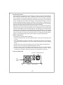
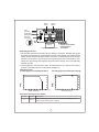
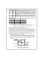
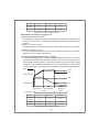
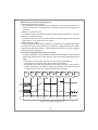
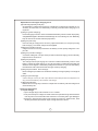
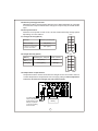
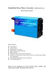
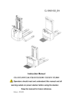
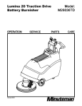
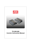
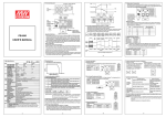
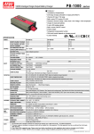
PB-600
Instruction Manual
PB-600 Instruction Manual
Index
0.Product description................................................................................. 1
1.Notes on operation ................................................................................. 1
2.Front and back panel .............................................................................. 1
3.Derating curve ........................................................................................ 2
3.1 Charging current VS temperature...................................................... 2
3.2 Charging current VS input voltage ..................................................... 2
4.Function description for CN100 ............................................................... 2
5.LED Indication ........................................................................................ 3
6.Explanation of operation logic (charging stages)...................................... 3
6.1 2 stage charging (flick switch to "2" stage)......................................... 3
6.2 3 stage charging (flick switch to "3" stage)......................................... 4
6.3 8 stage charging (flick switch to "8" stage)......................................... 5
7.Function description ............................................................................... 6
7.1 Input voltage .................................................................................... 6
7.2 PFC ................................................................................................. 6
7.3 Remote control ................................................................................. 6
7.4 2, 3, or 8 stage charging mode selection ........................................... 7
7.5 Reverse polarity protection ............................................................... 7
7.6 Fan speed control ............................................................................. 7
7.7 Charger OK relay (RY15) .................................................................. 7
7.8 Output OK relay (RY13) .................................................................... 8
7.9 Temperature compensation .............................................................. 8
8.Wiring for battery................................................................................... 8
9.Suggested battery capacity ..................................................................... 9
10.Series and parallel connection of batteries ............................................ 9
11.Recommended wire specification ....................................................... 9
12.Failure correction notes ........................................................................ 10
Sep. 2014 Version 11
0.Product description
PB-600 is MW's next generation smart charger. It has many of the protective features
that consumers would like to have in a charger including battery misconnection
(wrong voltage), reverse polarity, battery disconnection or not connected, and battery
failure analysis. The latest high efficiency switching topology plus microcontroller
power management are utilized in its design. Three types of charging curves are
offered for lead acid battery charging, 2 stages for quick charging, 3 stages (quick +
float), and 8 stages for optimized charging. Charging stage selection can be easily
made by the user through the selection switch on the front panel.
Depending on battery brand and type (lead acid, gel, lithium iron, and lithium manganese);
the battery may require special charging curves and adjustment to the protective
functions which differs from the standard settings. The charging curves and protective
functions can be customized by reprogramming its firmware. Basically, you can change
the voltage/current settings of each individual stage plus adjust or cancel the protective
functions. Please note, the factory charging curve is for charging lead-acid battery.
Please contact MW regarding other types of battery charging requirements.
1.Notes on operation:
◎Designed for charging lead acid battery.
◎Must be installed in a dry and well ventilated area. It should not be exposed to rain
or snow.
◎The cables between charger and battery should be kept as short as possible to
prevent excessive voltage drop. Too much voltage drop will lead to longer charging
period.
◎Please make sure charging voltage and current meets battery specification.
◎Refrain from connecting new and old batteries in series.
◎Charger should be in the OFF mode before making battery connection or disconnection.
◎Three years warranty is provided under normal operating conditions. Failure
resulting from improper operation will result in cancellation of warranty.
2.Front and back panel
AC INLET ON/OFF SWITCH
ON
Fan
Ventilation
Hole
OFF
AC INPUT
Figure 2.1 Front Panel
1
Battery
Positive
LED
Indicator
Common
Negative
Power
Stage 8/3/2
2/3/8 stage
selection switch
Function
Connector
10
+
WARNING :
-
Please check battery
polarity before
connection
Battery
Figure 2.2 Back Panel
Assembly guidelines:
1.The charger should be turned OFF prior to battery connection. Suitable wire gauge
should be chosen based on rated charging current of the charger unit. Double-check
battery polarity before making the battery connection. Positive terminal of the charger
must be connected to + of the battery and negative terminal to of the battery. Also,
make sure the positive and negative terminals of the charger are not accidentally
shorted together.
2. After plugging in the AC power cable, flick the ON/OFF (0/-) switch to the ON(-)
position. The LED indicator on the switch will light up.
3.Derating curve
3.1 Charging current VS temperature
3.2 Charging current VS input voltage
100
100
90
80
80
60
70
60
40
50
20
-20
40
0
10
20
30
40
50
60
70 (HORIZONTAL)
90
95
100
115
264
INPUT VOLTAGE (VAC) 60Hz
AMBIENT TEMPERATURE (℃)
4.Function description for CN100
Pin No.
1,2
Function Description
RY13
Relay contact rating (max.): 30V/1A. "Short" when battery is full.
"Open" when battery is still charging.
2
Pin No.
Function Description
5,6
RY15
Relay contact rating (max.): 30V/1A. "Short" when the unit is working
normally; “Open” when the unit is in a faulty condition
7,8
Temperature sensor which comes with the charger can be connected
to the unit to allow temperature compensation of the charging voltage.
GND/RTH
If the temperature sensor is not used, the charger can still work
normally.
9,10
RC-/RC+
Turn the output ON and OFF by electrical or dry contact between
pin10 (RC+) and pin9 (RC-). Open: start charging. Short: stop charging.
5.LED Indication
Color
Status
Steady
Red
Flashing
Fail
Orange
Charging
Green
Full
Charging
Types of failure: 1 Battery disconnected 2 Damaged battery
3 Reverse polarity
4 Incorrect battery voltage (e.g. PB-600-12 connected to 24V battery)
5 Activation of protection function (e.g. OTP, OVP, and Short)
6.Explanation of operation logic (charging stages):
PB-600 has a total of 3 charging modes to choose from, 2 stages, 3 stages, and
8 stages. 8 stages charging differ from 2 stages with the addition of pulse, soft start,
analysis, recondition, float, and maintain stages. 2 stages provide simple and quick
charging. 3 stages is similar to 2 stages with the exception of not shutting OFF after
the battery is fully charged. Lastly, 8 stages will allow charging to maximum capacity.
User can select between 2,3 or 8 stages depending on their requirement.
6.1 2 stage charging (flick switch to "2" stage)
During initial charge (stage 1), charger will provide maximum current to the battery.
The built-in fan will also turn ON. As the battery starts to get full, charging current
will gradually decrease (stage 2). When charging current decrease to less than
10% of max. LED indicator will turn Green to show a full charge and the charger
will turn OFF.
Start
V boost
Charge Voltage
100%
10%
Charge Current
stage 1
stage 2
Constant Current Constant Voltage
Color of LED
Orange
3
Battery Full
Green
State
PB-600-12
PB-600-24
PB-600-48
Constant
Current
40A
21A
10.5A
V boost
14.4V
28.8V
57.6V
Figure 6.1 2 stage charging curve
Explanation for 2 stages charging curve
(0)Initial stage (battery analysis):
Check battery voltage level to see if it is within the normal range, whether or not
a battery is connected, or if the battery is already full and further charging is not
required.
(1)Stage 1 (constant current):
A constant current is provided so the battery can be quickly charged to 2.4V per cell.
(2)Stage 2 (constant voltage):
A constant voltage of 2.4V per cell is provided until the charging current naturally
tapers down to 10% then stop charging.
6.2 3 stage charging (flick switch to "3" stage)
During initial charge (stage 1), charger will provide maximum current to the battery.
The built-in fan will also turn ON. As the battery starts to get full, charging current
will gradually decrease (stage 2: programmed to last no longer than 24hrs). When
charging current decrease to less than 10% of max. LED indicator will turn Green
to show a full charge. The charger will now maintain a float charge voltage (stage 3).
Start
V boost
V float
Charge Voltage
100%
10%
Charge Current
stage 1
Constant Current
stage 2
stage 3
Constant Voltage
Battery Full
Orange
Color of LED
Green
State
PB-600-12
PB-600-24
PB-600-48
Constant
Current
40A
21A
10.5A
V boost
V float
14.4V
13.8V
28.8V
27.6V
57.6V
55.2V
Figure 6.2 3 stage charging curve
4
Explanation for 3 stages charging curve
(0)Initial stage (battery analysis):
Check battery voltage level to see if it is within the normal range, whether or not
a battery is connected, or if the battery is already full and further charging is not
required.
(1)Stage 1 (constant current):
A constant current is provided so the battery can be quickly charged to 2.4V per cell.
(2)Stage 2 (constant voltage):
A constant voltage of 2.4V per cell is provided until the charging current naturally
tapers down to 10% then move on to stage 3.
(3)Stage 3 (Float voltage):
A float voltage of 2.3V per cell is provided so that the battery can maintain full charge.
*For applications that utilize the charger (PB-600) to charge batteries and supply
system power simultaneously(e.g. UPS system), please select "3 stage" charging
for the best use of the charger.
6.3 8 stage charging (flick switch to "8" stage)
8 stage charging provides optimized charge to lead acid battery. It also prolongs
battery life and increase storage capacity. Some of the main advantages are as
below:
◎Advantage of pulse stage: Use pulse current to revive aged battery.
◎Advantage of recondition stage: Allow full charge of battery.
◎Advantage of float and maintain stage: After LED turns green, maintenance
charge is provided so the battery is always in a full state. User will have access
to a full battery whenever it is disconnected from the charger.
Start
Pulse
Charge
Soft
Start
Constant
Current
Constant
Voltage
Battery
Analysis
Recondition
Float
Charge
Maintain
Pulse
Soft
Start
Constant
Current
Constant
Voltage
Analysis
Recond
Float
Maintain
stage 1
stage 2
stage 3
stage 4
stage 5
stage 6
stage 7
stage 8
Charge
Voltage
Charge
Current
Color of
LED
Orange
Green
Figure 6.3 8 stage charging curve
5
Explanation for 8 stages charging curve
(0)Initial stage (battery analysis):
Check battery voltage level to see if it is within the normal range, whether or not
a battery is connected, or if the battery is already full and further charging is not
required.
(1)Stage 1 (pulse charging):
Pulse charging is used to revive tired lead acid battery which is either improperly
charged/discharged or allowed to self-discharge as occurs during non-use. Basically,
help to restore its normal chemical properties.
(2)Stage 2 (soft start):
Use low charge voltage and current to prepare the battery to accept upcoming
bulk charging, so a better charge can be applied.
(3)Stage 3 (constant current):
A high constant current is provided so the battery can be quickly charged to 2.4V
per cell.
(4)Stage 4 (constant voltage):
A constant voltage of 2.4V per cell is provided until the charging current naturally
tapers down to a low level.
(5)Stage 5 (analysis):
The charger will stop charging for 2 minutes to determine battery status. If the
battery voltage is higher than 2.1V per cell, the battery is determined as OK and
will move on to stage 6. If the battery voltage is lower than 2.1V per cell, the battery
fail indication will come ON and the charger will stop charging.
(6)Stage 6 (recondition boost charge):
Boost voltage is provided to recondition the battery storage capacity to its original
state.
(7)Stage 7 (float charge):
A float voltage of 2.3V per cell is provided for extended period of time(about one
day) so that the battery can maintain full charge.
(8) Stage 8 (maintain):
Maintenance charge is provided to compensate for battery self-discharge and
extend battery life.
7.Function description
7 .1 Input voltage
◎Input voltage range is 90~264Vac or 127~370Vdc.
◎The provided input voltage must fall within the specified range otherwise the
unit may be non-functional also the active PFC circuit may fail or get damaged.
◎Efficiency will get lower when input voltage is at low line. Please note, load
derating will be required when input voltage is below 100Vac.
6
7.2 PFC
◎Built-in active PFC circuit: PF>0.95 when input voltage is between 90~230Vac
with full load at the output. On the other hand, if the input voltage is >230V or
output is not at full load, the PF will drop below 0.95.
7.3 Remote control
The charger can be turned ON/OFF by using the "remote control" function.
Between RC+ (pin10)
and RC- (pin9)
Charger
SW open
ON
SW closed
OFF
CN100
1 RY13 RY13 2
Power
Stage 8/3/2
NC
NC
RY15 RY15
10
GND RTH
9
+
-
RC- RC+
10
Battery
SW
7.4 2, 3, or 8 stage charging mode selection
The charger features user selectable 2, 3, or 8 stage charging. The charging
profile is selected by moving the slide switch on the back panel.
Switch
Charging mode
Slide right
2 stage charging
Middle
3 stage charging
Slide left
8 stage charging
Power
Stage 8/3/2
10
Stage 8/3/2
+
-
Battery
7
7.5 Reverse polarity protection
With built-in battery reverse polarity detection circuit. When the battery is connected
in reverse at the output terminal of the charger, the output relay circuit will remain
open.
7.6 Fan speed control
With built-in fan speed control circuit, the fan will automatically change speed
depending on load condition.
CN100
7.7 Charger OK relay (RY15)
Charger
1 RY13 RY13 2
NC
Between pin5 and pin6
NC
RY15 RY15
Work normally
ON (short)
Failure or protection
function activated
OFF (open)
GND RTH
9
RC- RC+ 10
RY15
7.8 Output OK relay (RY13)
CN100
1
Between pin1 and pin2
Color of LED
Battery full
ON (short)
Green
Charging
OFF (open)
Orange
Battery
RY13 RY13
NC
2
NC
RY15 RY15
GND RTH
9
RC- RC+ 10
RY13
7. 9 Temperature compensation
Temperature sensor which comes with the charger can be connected to the unit
to allow temperature compensation of the charging voltage. If the temperature
sensor is not used, the charger can still work normally.
Power
Stage 8/3/2
10
The temperature
sensor can either
be attached to the
battery or placed
in its surrounding
environment.
+
-
Battery
NTC
8
8.Wiring for battery
Select suitable wire guage based on rated charging current. Refer to the following
table for minimum wire gauge. We highly recommend using RED wire for + connection
and BLACK wire for-connection:
CROSS SECTION(mm 2 )
AWG
Max. Current(A)
UL1015(600V 105℃)
14
2.1
12
12
3.3
22
10
5.3
35
7
10
46
6
16
60
4
25
80
9.Suggested battery capacity
Model
Battery capacity
PB-600-12
135-400AH
PB-600-24
70-210AH
PB-600-48
35-105AH
Note: 1.Using battery capacity larger than the suggested value will not lead to damage
of the battery. The main drawback is it may take longer to fully charge the
battery.
2.If you're unsure about max allowable charging current of your battery, please
refer to the battery's technical specification or consult its manufacturer.
10.Series and parallel connection of batteries
1.Batteries in series
Voltage can be doubled when 2 batteries are connected in series. However, the
capacity (Ah) will remain the same. For example, 2 x 12V 100Ah batteries connected
in series = 24V 100Ah.
+
Battery
-
+
-
Battery
9
2.Batteries in parallel
Wh en 2 bat ter ies a re c onnect ed i n pa ral lel, v olta ge r em ai ns th e s am e a nd t he
capacity (Ah) doubles. For example, 2 x 12V 100Ah batteries connected in parallel
= 12V 200Ah.
+
-
Battery
+
-
Battery
11.Recommended wire specification
Installation
Safety rating
Maximum length
Desktop, counter top, chassis
box (mobile)
SP-2, SPE-2, SPT-2,SV,SVE,SVT
10ft (3 meter)
Grounded, fixed in place
(not mobile)
S, SE, SO, SP-3, SPT-3, ST, STO,
SJ, SJE, SJO, SJT, SJTO
Not specified
Note: Please install in accordance with the table above. Wire gauge should be no
smaller than No. 18 AWG/3C. Socket type restricted to 15A, 125V (NEMA 5-15P)
or 15A, 250V(NEMA 6-15P) with power cord length ranging from 1.8 meters
to 10 meters.
12.Failure correction notes
Status
Unable to
charge
the battery
LED indicator
does not turn
Green after a
long charging
period
Possible reasons
Solutions
ON/OFF switch in the OFF position
Switch to the ON position
Battery reverse polarity
Reconnect using the
right polarity
Battery with higher voltage is
connected
Use battery with the
correct voltage
Input AC voltage is too low
Make sure input source
is between 90~264VAC
Battery exceeded lifespan or
damaged
Replace with a new
battery
Output cables are too thin
Replace with suitable
wire gauge
If you are not able to clear the failure condition, please contact Mean Well or
any of our distributors for repair service.
10
N o . 2 8 , W u q u a n 3 r d R d . , Wu g u D i s t . , N e w Ta i p e i C i t y 2 4 8 , Ta i w a n