1
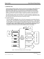
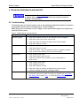
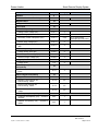
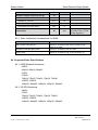
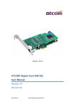
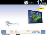
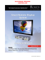
ELECTRONIC REVISION CONTROLLED Document Number 106957 Rev A Rosen Aviation Smart Remote Display System Technical Manual, Smart Remote Display System © 2014 by Rosen Aviation, LLC All Rights Reserved The information contained herein is proprietary to Rosen Aviation, LLC. No part of this publication may be reproduced, transmitted, transcribed, stored in a retrieval system, or translated into any language in any form by any means without the written authorization from Rosen Aviation, LLC, except as allowed under copyright laws. Trademarks Venue and CES are trademarks of Rockwell Collins, Inc. Disclaimer of Liability The information contained in this document is subject to change without notice. Because we are continuously improving and adding features to our products, Rosen Aviation, LLC reserves the right to change specifications without prior notice. Rosen Aviation, LLC shall not be liable for technical or editorial errors or omissions contained herein. Rosen Aviation, LLC 1020 Owen Loop South Eugene, OR 97402 541.342.3802 888.668.4955 Fax: 541.342.4912 www.rosenaviation.com Document Number: 106957 Template: 4.4.1.6FM2; Revision A; 12/06/12 Revision: Date: 03/13/14 A Page 2 of 24 Rosen Aviation Smart Remote Display System Contents 1. INTRODUCTION.............................................................................................................................. 5 1.1. System Overview ...................................................................................................................... 5 1.2. Smart Remote Display System Components ....................................................................... 6 1.2.1. Technical Drawings................................................................................................................6 2. INPUTS/OUTPUTS.......................................................................................................................... 6 2.1. Smart RMEB Configurations ................................................................................................... 7 3. REMOTE DISPLAY MODULE INSTALLATION GUIDELINES .............................................. 7 3.1. Mounting Configurations.......................................................................................................... 7 3.1.1. Bulkhead Mounting Requirements ........................................................................................8 4. ASSEMBLY INSTRUCTIONS FOR COSMETIC COMPONENTS ......................................... 8 4.1. Mounting Cosmetic Backs to a Bulkhead ............................................................................. 8 4.2. Attaching an RDM to a Cosmetic Back ................................................................................. 9 4.3. Mounting a Bezel .................................................................................................................... 10 5. SYSTEM CONNECTIONS ........................................................................................................... 10 5.1. Pinout Connections ................................................................................................................ 11 5.2. Address Strapping .................................................................................................................. 11 6. INITIAL POWER UP...................................................................................................................... 14 6.1. No Video Signal ...................................................................................................................... 14 7. MAINTENANCE OSD MENU ...................................................................................................... 15 7.1. Picture-quality Controls.......................................................................................................... 15 7.2. Backlight ................................................................................................................................... 16 7.3. Hue............................................................................................................................................ 16 7.4. Aspect Ratio ............................................................................................................................ 16 7.5. Advanced Menu ...................................................................................................................... 17 7.5.1. Color Gains: Red, Green, Blue ............................................................................................17 7.5.2. Horizontal and Vertical Adjustments....................................................................................18 7.5.3. Overscan ..............................................................................................................................18 7.5.4. Factory Default .....................................................................................................................18 7.6. Exit ............................................................................................................................................ 18 8. TECHNICAL REFERENCES AND SUPPORT......................................................................... 19 8.1. Troubleshooting ...................................................................................................................... 19 8.2. Cleaning the Displays ............................................................................................................ 20 8.3. RTCA DO-160G Qualifications for Displays ....................................................................... 20 8.3.1. Other Certification Considerations for RDMs ......................................................................22 Document Number: 106957 Template: 4.4.1.6FM2; Revision A; 12/06/12 Revision: Date: 03/13/14 A Page 3 of 24 Rosen Aviation Smart Remote Display System 8.4. Supported Video Specifications ........................................................................................... 22 8.4.1. HDMI Standard Resolutions ................................................................................................22 8.4.2. 3G-SDI Resolutions .............................................................................................................22 9. DEFINITIONS ................................................................................................................................. 23 10. REVISION HISTORY .................................................................................................................. 24 Document Number: 106957 Template: 4.4.1.6FM2; Revision A; 12/06/12 Revision: Date: 03/13/14 A Page 4 of 24 Rosen Aviation Smart Remote Display System 1. INTRODUCTION The Smart Remote Display System consists of an ultra-thin remote display module (RDM) and a smart, high-definition remote electronics box that can run an extra peripheral SDI display to maximize the viewing experience. The remote electronics design provides more mounting flexibility because the video processing electronics box can be located up to 50 feet from the displays. The high-definition display modules are available in a range of screen sizes and the mounting options allow customers to configure a system that fits their aircraft’s cabin interior. This manual provides general instructions about how to install all bulkhead configurations of the Smart Remote Display System onto your aircraft. It contains everything you need to know to wire the components and confirm that the system is functioning correctly. 1.1. System Overview The Smart RMEB (P/N 0700-150) (P/N 441-2028-100) is designed for aircraft with a Rockwell Collins’ Venue™ Cabin Management System and Cabin Electronics System™ (CES). Although the Smart RMEB can operate a second 3G-SDI display using RS-232 control and SDI cable to route the digital video sources/signals, the Rockwell Collins’ application software will select only one display at a time—either the RDM or the SDI. The interface circuitry and wiring is identical for all Remote Display Module (RDM) configurations; the only difference between the configurations is the amount of power the Smart RMEB provides to the displays. RS-232 SDI Ethernet Interface Power Output USB 2.0 HDMI IN 3G-SDI IN Power Input 28VDC only Smart Remote Electronics Monitor Box (RMEB) Display RS-232 Serialized Video Output Rosen Display (RDM) CES or Venue CMS SDI Display Analog (L/R) Audio Output Figure 1 Smart Remote Display System functional diagram Document Number: 106957 Template: 4.4.1.6FM2; Revision A; 12/06/12 Revision: Date: 03/13/14 A Page 5 of 24 Rosen Aviation Smart Remote Display System 1.2. Smart Remote Display System Components Each Smart RMEB will operate one RDM. To complete your RDM installation, the following cosmetic components are also available: Remote Display Modules (RDM) are available in sizes: 19”, 22”, 24”, 26”, 32”, 42”, and 55” Mounting accessories: front bezel, cosmetic back, and credenza lift Connector kits (sold separately) – see the technical drawing for specific part numbers 1.2.1. Technical Drawings Technical drawings are available for all components of the Smart Display system. Consult them for information about the following features: Installation dimensions Pinout descriptions Specifications – performance and environmental External connectors and interconnect cabling 2. INPUTS/OUTPUTS In addition to an RDM, you can also connect a second peripheral SDI display to the Smart RMEB. The unit’s SDI video output will support any SDI display that is compatible with Rockwell Collins’ protocol through RS-232. It scales and distributes HDMI, internal processor-generated video, and streaming Ethernet video input simultaneously to the RDM and peripheral SDI display outputs at 1080p/60 resolution. The Smart RMEB also supports the following functions: Distributes 3G-SDI video input to either the RDM or the peripheral SDI display. Distributes stereo analog audio for the associated HDMI, HD-SDI, Ethernet, and internal processor-generated video. Hosts an Audio and Video on Demand (AVOD) application - for decoding digital media files (H.264, MPEG1/2, and MP3) and distribution of the audio and video. Interfaces with USB 2.0 Mass Storage Devices in support of the AVOD feature. Hosts interactive Rockwell Collins’ moving map application - for simultaneous distribution to the RDM and peripheral SDI display. A 100BASE-T Ethernet communication with Venue and CES systems. RS-232 communication to the peripheral SDI display. Document Number: 106957 Template: 4.4.1.6FM2; Revision A; 12/06/12 Revision: Date: 03/13/14 A Page 6 of 24 Rosen Aviation Smart Remote Display System 2.1. Smart RMEB Configurations The Smart RMEB has several possible operational mode configurations, depending on the specific aircraft installation. The unit has four possible media inputs (HDMI, SDI, Streaming Video over Ethernet, or USB), two possible video outputs (RDM and a peripheral SDI Display), and a single analog audio output for consistent sound quality at any volume. Additionally, the system can play media from the internal solid-state storage drive. During typical operations, a single media source is selected as the priority output at any given time, and the priority media source can be simultaneously distributed to (either one or both of) the displays and the audio output device. (Note: Rockwell Collins’ cabin management system has the ability to disable either display.) 3. REMOTE DISPLAY MODULE INSTALLATION GUIDELINES 3.1. Mounting Configurations Remote Display Modules (RDMs) have three distinct mounting options: flush mount, semi-proud mount, and proud mount configurations. The RDMs can be flush mounted, mounted with a sleek bezel (semi-proud), or proud-mounted between a bezel and cosmetic back. The photos below are representative of the different bulkhead mounting options for the remote displays. Please contact your sales associate for specific configurations. RDM Flush mount Front bezel Semi-proud mount Cosmetic back Proud mount Figure 2 Mounting options for RDMs Flush mount – RDM only Semi-proud mount – RDM with bezel Proud mount – RDM with bezel and a cosmetic back Document Number: 106957 Template: 4.4.1.6FM2; Revision A; 12/06/12 Revision: Date: 03/13/14 A Page 7 of 24 Rosen Aviation Smart Remote Display System 3.1.1. Bulkhead Mounting Requirements The Smart RMEB and RDMs do not require any external forced-air cooling. A flush mounted RDM can mount either from the back, through an interior wall, or from the front mounting tabs. Proud-mounted RDMs must attach from the front into the cosmetic back. Use the technical drawings to assist in the installation process. Pay close attention to the dimensions when considering installation requirements. Dimensions for some models may vary, so be sure to consult the latest drawings. Touching the LCD with excessive force may leave pressure spots that show in video display. Handle with care. 4. ASSEMBLY INSTRUCTIONS FOR COSMETIC COMPONENTS This section provides instructions about how to assemble the cosmetic backs and bezels. To add a stylish, proud-mount option, mount the cosmetic back to the bulkhead, attach the RDM to the cosmetic back, and then snap on the bezel. Note: Protect cosmetic and sensitive components from scratches, nicks, and debris during hardware installation. 4.1. Mounting Cosmetic Backs to a Bulkhead The cosmetic backs use two different types of mounting brackets, depending on the size of RDM that you install. The cosmetic backs are a universal fit—there is no top or bottom. Technical drawings for the Remote Display System accessories are available on the separate high-definition display product pages on the Rosen Aviation website. Attach the 19”, 22”, 24”, and 26” cosmetic back to the bulkhead using the four mounting brackets and a minimum of four FHP screws (customer supplied) in the .188 mounting holes, as shown below. Attach to bulkhead Attach to RDM Figure 3 1901-, 2201-, 2401-, and 2601-800 cosmetic back mounting tabs Document Number: 106957 Template: 4.4.1.6FM2; Revision A; 12/06/12 Revision: Date: 03/13/14 A Page 8 of 24 Rosen Aviation Smart Remote Display System Attach the 32” cosmetic back to the bulkhead using six #6 100 FHP screws (customer supplied). Attach the 42” cosmetic back to the bulkhead using ten #6 100 FHP screws (customer supplied). Attach the 55” cosmetic back to the bulkhead using twelve #6 100 FHP screws (customer supplied) Attach to bulkhead Attach to RDM Figure 4 3201-800, 4201-800, and 5501-800 cosmetic back mounting bracket 4.2. Attaching an RDM to a Cosmetic Back Figure 5 shows an exploded view of a proud-mount assembly. Align the four tabs on the RDM with the four mounting brackets on the cosmetic back. Secure with two 4-40 fasteners in each tab/bracket. For more dimensional information, see the technical drawings for your specific assembly. Mounting brackets on the cosmetic back Figure 5 RDM with a proud-mount bezel assembly Document Number: 106957 Template: 4.4.1.6FM2; Revision A; 12/06/12 Revision: Date: 03/13/14 A Page 9 of 24 Rosen Aviation Smart Remote Display System 4.3. Mounting a Bezel Mount the cosmetic back and monitor before attaching the bezel. To attach a bezel to a RDM, align the mounting bosses with the monitor standoffs and gently press on the retaining clips to snap the bezel into place. Bezels attach around the perimeter of the RDMs with retention fasteners. The quantity and type of bezel fasteners varies depending on the size of the bezel and RDM. Figure 6 shows the different assembled retention fasteners on the bezels. Only wire retaining clips on 19”–26” bezels Top and bottom wire clips Ball stud receivers on 32”, 42”, and 55” bezel sides Figure 6 Different bezel retention fasteners 5. SYSTEM CONNECTIONS Figure 7 shows the Smart RMEB’s front panel connectors. The Smart RMEB outputs a serialized video signal via an RJ-45 cable from P4 and provides conditioned power and control to the RDM via a harness with DA15 connectors from J3. HDMI video input Aircraft power 3G-SDI input 3G-SDI peripheral display Aircraft I/O Ethernet 3G-SDI streaming, USB 2.0, peripheral display audio output RS-232 RDM video RDM power controls Figure 7 Smart Remote Display System connections Document Number: 106957 Template: 4.4.1.6FM2; Revision A; 12/06/12 Revision: Date: 03/13/14 A Page 10 of 24 Rosen Aviation Smart Remote Display System The RDM receives power, control, and serialized video from the Smart RMEB located up to 50 feet away, as shown below. To obtain information about interconnect cables, please contact Rosen Aviation’s Technical Support at 541.434.4512 and request the Interconnect Cable Specification for Venue System Remote Electronics (P/N 107175). The peripheral SDI display may be located up to 75 feet away from the Smart RMEB. Please contact Rockwell Collins for cable specifications. Figure 8 Smart Remote Display system connections 5.1. Pinout Connections There are several ways to connect the remote display system to an aircraft’s entertainment system. Follow the pinout descriptions on the technical drawing (P/N 0700-150-CD) to assist in completing the wiring connections. Note: This display is for entertainment purposes only; connect to a non-critical power bus. 5.2. Address Strapping The Smart RMEB has different IP addresses based on the platform mode that you set. 5.2.1. Factory Mode From the factory, the Smart RMEB will have an IP Address set to 10.10.10.50 with a netmask of 255.255.255.0. The factory mode IP Address is always hardcoded; therefore, you do not have to set the address bit pins. The address bit pins are pins 1 thru 5 on the P2 connector. Document Number: 106957 Template: 4.4.1.6FM2; Revision A; 12/06/12 Revision: Date: 03/13/14 A Page 11 of 24 Rosen Aviation Smart Remote Display System 5.2.2. Venue Mode The Smart RMEB in the Venue mode has an IP Address of 10.240.11.xx with a netmask of 255.240.0.0. The last octet of the IP address (xx) is calculated on how the address bit pins 1 thru 5 are wired on the P2 Connector. To specify an IP address of 10.240.11.1, wire the address bit pins 1 thru 5 on the Smart RMEB as follows. Table 1 A Smart RMEB IP address of 10.240.11.1 for Venue mode P2 Connector Pin 5 P2 Connector Pin 1 P2 Connector Pin 2 P2 Connector Pin 3 P2 Connector Pin 4 Bit 4 Bit 3 Bit 2 Bit 1 Bit 0 OPEN OPEN OPEN OPEN GND Note: In the table above, only Bit 0 is tied to ground and all other bits are OPEN. This combination gives binary 00001, resulting in value of 1 in decimal. Similarly, if the Smart RMEB needs an IP address of 10.240.11.2, the address bit pin 3 (Bit 1) needs to grounded and the other pins need to be left OPEN, as follows: Table 2 A Smart RMEB IP address of 10.240.11.2 for Venue mode P2 Connector Pin 5 P2 Connector Pin 1 P2 Connector Pin 2 P2 Connector Pin 3 P2 Connector Pin 4 Bit 4 Bit 3 Bit 2 Bit 1 Bit 0 OPEN OPEN OPEN GND OPEN The IP Address of the RMEB in Venue mode will range between 10.240.11.1 and 10.240.11.31, based on how you wire the address pins 1 thru 5. Note: If all address bit pins are OPEN, the resulting IP address will be 10.240.11.0 and this is an invalid IP address for Venue mode. All IP addresses must be between 10.240.11.1 and 10.240.11.31. Each Smart RMEB must have a unique IP address on the network. Multiple Smart RMEBs with same IP address are invalid. Document Number: 106957 Template: 4.4.1.6FM2; Revision A; 12/06/12 Revision: Date: 03/13/14 A Page 12 of 24 Rosen Aviation Smart Remote Display System Up to thirty-two (32) unique IP addresses are available in Venue mode, as shown in Table 3, where 1 = OPEN and 0 = GROUND. Table 3 Valid IP addresses for the Smart RMEB in Venue mode ID Parity Bit (Pin 5) Bit 4 Pin 1 Bit 3 Pin 2 Bit 2 Pin 3 Bit 1 Pin4 Bit 0 Smart RMEB IP Address (xx) 0 0 0 0 0 0 (Not used) 0 0 0 0 1 1 0 0 0 1 0 2 0 0 0 1 1 3 0 0 1 0 0 4 0 0 1 0 1 5 0 0 1 1 0 6 0 0 1 1 1 7 0 1 0 0 0 8 0 1 0 0 1 9 0 1 0 1 0 10 0 1 0 1 1 11 0 1 1 0 0 12 0 1 1 0 1 13 0 1 1 1 0 14 0 1 1 1 1 15 1 0 0 0 0 16 1 0 0 0 1 17 1 0 0 1 0 18 1 0 0 1 1 19 1 0 1 0 0 20 1 0 1 0 1 21 1 0 1 1 0 22 1 0 1 1 1 23 1 1 0 0 0 24 1 1 0 0 1 25 1 1 0 1 0 26 1 1 0 1 1 27 1 1 1 0 0 28 1 1 1 0 1 29 1 1 1 1 0 30 1 1 1 1 1 31 Document Number: 106957 Template: 4.4.1.6FM2; Revision A; 12/06/12 Revision: Date: 03/13/14 A Page 13 of 24 Rosen Aviation Smart Remote Display System 6. INITIAL POWER UP Make sure that power is turned off and connect the following harnesses to the Smart RMEB connectors: 1. Attach secure ground connections on the Smart RMEB housing and monitor chassis grounding lugs. 2. Connect an Ethernet communication harness to P2. Refer to the Smart RMEB Outline and Installation Drawing (P/N 0700-150-CD) for pinout information. 3. Connect 28 VDC power to the Power connector. Verify that the circuit breakers being used with the Smart RMEB meet the power requirements for the display size as stated in the Smart RMEB technical drawing. Also, avoid coiling the power wire as this can cause heat to build up in the wire. If you have more questions about power requirements, contact Rosen Aviation’s Technical Support at 541.434.4512. 4. Attach a DA-15 interconnect cable to the RDM DA-15 pigtail and connect to J3 on the Smart RMEB. Do not connect these pins to any other location. 5. Attach an RJ-45 interconnect cable to the RDM’s RJ-45 pigtail and connect to P4. Ground and strain relieve harnesses on the RJ-45 connectors using the brackets provided. 6. Attach a DB-9 interconnect cable to the peripheral SDI display and connect to J1 on the Smart RMEB. 7. Connect the available video inputs. 8. Apply power and wait for a signal on the RDM (within 30 seconds). The default setting for the Smart RMEB is Auto Off, until the Rockwell Collins’ application commands the display to be On, and the default source is 3G-SDI. Do not plug or unplug the display connector while power is applied. When cycling power, leave unit off for 20 seconds before restoring power. 6.1. No Video Signal The Smart RMEB’s operating system will complete a boot-up to the point of launching system applications within sixty (60) seconds from application of power. If there is no input video source for more than three seconds, the following message will appear on the screen. Figure 9 Video status indicator Document Number: 106957 Template: 4.4.1.6FM2; Revision A; 12/06/12 Revision: Date: 03/13/14 A Page 14 of 24 Rosen Aviation Smart Remote Display System 7. MAINTENANCE OSD MENU Note: Depending on the installation, the Maintenance OSD Menu may not be visible in the application. An interactive, on-screen display (OSD) menu for managing certain video settings on the RDM is accessible through the Maintenance Mode of the Rockwell Collins’ application software. There are two pages of OSD options, and you access the second page by selecting the Advanced option, as shown below. To choose a value, use the navigation commands left/up and right/down, and then choose SELECT to confirm the setting. For more information about the navigational commands, refer to the Rockwell application software. Yellow highlight shows which option is active Use Advanced to open page 2 of the OSD Figure 10 Maintenance OSD Menu (page 1) Note: The on-screen display will timeout and close automatically after no screen activity for 15 seconds. 7.1. Picture-quality Controls The Brightness, Contrast, and Saturation menu options use control bars to fine-tune different aspects of the picture quality on the RDM. To adjust these options, highlight the parameter to open a control bar and adjust the value, similar to Figure 11 below. Set the intensity level by increasing or decreasing the control’s value. The adjustment range is 0 to 100. Figure 11 Sample picture-quality control bar Document Number: 106957 Template: 4.4.1.6FM2; Revision A; 12/06/12 Revision: Date: 03/13/14 A Page 15 of 24 Rosen Aviation Smart Remote Display System 7.2. Backlight To adjust the intensity of the RDM’s backlight, select Backlight to open the control bar, as shown in Figure 12. The adjustment range for the Backlight value is 0 to 100. Figure 12 Backlight control bar 7.3. Hue To adjust the tint or color shades of the RDM’s screen, select Hue to open the control bar, as shown in Figure 13. The adjustment range for the Hue level is 0 to 360. Figure 13 Hue control bar 7.4. Aspect Ratio Use Aspect Ratio to adjust the picture expansion to match the encoding of the HDMI and 3G-SDI video inputs. Aspect ratio changes the appearance of the picture to a different format. To switch the display between aspect ratio modes, select Aspect Ratio and then one of four modes, as shown in Figure 14. Watch for proportional changes in the background picture and choose the optimal mode for the source. To choose a value, the navigation commands retreat (left/up) and advance (right/down) through the list of possible values, and then choose SELECT to confirm the selection. Figure 14 Aspect Ratio modes TRUE: (Default) Displays the input video signal without any modification. When you set the Smart RMEB to TRUE aspect ratio, the boxed image will be displayed for various input signal formats, except that it is not available for 480i and 576i formats. Use this setting for calibration and video quality troubleshooting. NORMAL: Expands the input signal in the vertical dimension to fill the full height of the screen while maintaining an original aspect ratio. When you set the Smart RMEB to Normal, a standard 4:3 source image will appear with vertical black bars on the left and right side of the image. Black bars (part of the input video signal) will be displayed on the top and bottom of the screen when you view 1.85:1 and 2.35:1 source material using a 16:9 NORMAL aspect ratio. FULL: Displays standard 4:3 source video in 16:9 aspect ratio by expanding the image horizontally. Circles will appear as ovals in the central and outer portions of the screen. If the source image is letterboxed, there will be black bars at the top and bottom of the image. A 16:9 widescreen source will fill the screen with minimal distortion. Document Number: 106957 Template: 4.4.1.6FM2; Revision A; 12/06/12 Revision: Date: 03/13/14 A Page 16 of 24 Rosen Aviation Smart Remote Display System CINEMA: Expands the source video in the vertical and horizontal dimensions to fill the display screen. Letterbox-format DVDs will have small or no bars showing in this mode, while 4:3 aspect video sources will expand beyond the screen boundaries, appearing cropped. 7.5. Advanced Menu The Advanced menu contains a second page of OSD video settings to fine-tune the primary screen colors, picture position, overscan, and to restore the RDM’s factory screen settings. To open the menu shown in Figure 15, select Advanced from the first page of the OSD. Use Back to return to page 1 of the OSD Figure 15 Advanced Maintenance OSD Menu (page 2) 7.5.1. Color Gains: Red, Green, Blue Each of the color gain options adjusts the low-level registers of its respective color value in the picture. Select Advanced and then choose a color gain option. A control bar, similar to Figure 16, to adjust the option will appear. Red: Reducing the value will show more cyan-colored tones, and increasing the value will intensify the red tones. Green: Reducing the value will show more magenta tones, and increasing the value will intensify the green tones. Blue: Reducing the value will show more yellow tones, and increasing the value will intensify the blue tones. The adjustment range for the color gains is 0 to 100. Figure 16 Sample color-gain control bar Document Number: 106957 Template: 4.4.1.6FM2; Revision A; 12/06/12 Revision: Date: 03/13/14 A Page 17 of 24 Rosen Aviation Smart Remote Display System 7.5.2. Horizontal and Vertical Adjustments The Horizontal/Vertical Scale and Position settings enable you to shift the picture’s position to fill the screen. The Scale settings enable stretching/cropping an image and the Position settings enable you to shift the image horizontally or vertically, thus minimizing or eliminating the black bars at the edge of the picture. Select the Advanced and then choose an adjustment option. A control bar, similar to Figure 17, to adjust the option will appear. The range of values for these settings is -31 to +31, with a default of 0. Decreasing the Scale settings will reduce or crop the picture, and increasing them will stretch it in either direction. Decreasing the Position settings will shift the picture left/up, and increasing them will shift it right/down. Figure 17 Sample adjustment control bar 7.5.3. Overscan Use Overscan to conceal any screen anomalies that may be visible from either the HDMI or 3G-SDI input signals. When enabled, the setting cuts off a small percentage around the edges of the image and resizes it to fit full screen. You can set the overscan value for any source or format, but any video is scaled to 1080p. Select AdvancedOverscan and then choose a setting value. The options are 0% (Disabled), 1.67%, 2.5%, 5%, 7%, and 10%. The default is 0%. The overscanned image will automatically update when you switch between percentage values. You do not have to cycle power for the change to take effect. Figure 18 Overscan setting options 7.5.4. Factory Default Choose this option to perform a complete factory restore. It restores the default screen settings on all menu options to their factory settings. Highlight Yes. The OSD will close automatically after the Smart RMEB restores the default settings. 7.6. Exit Use Exit to close the Maintenance OSD Menu. Document Number: 106957 Template: 4.4.1.6FM2; Revision A; 12/06/12 Revision: Date: 03/13/14 A Page 18 of 24 Rosen Aviation Smart Remote Display System 8. TECHNICAL REFERENCES AND SUPPORT Always check the Rosen Aviation website under the Products tab to ensure that you are working with the most current revision of technical documentation. 8.1. Troubleshooting If the display does not function properly, refer to the following troubleshooting table for symptoms and possible solutions before contacting Rosen Technical Support. Note: Always use a multimeter to verify voltages. Check actual results against the requirements described in this manual. Table 4 Troubleshooting tips and solutions Problem No video (signal) Screen is black Image flickers Distorted Image Wrong Colors Document Number: 106957 Template: 4.4.1.6FM2; Revision A; 12/06/12 Possible Solutions Verify that the display is turned on and the video source is supplied. Verify that you are in the correct source mode. Verify that a signal is reaching the display using another display. Verify that the pinout is correct. Verify that the display is receiving power. Verify that the pinout is correct. Verify that the video source is supplied and a disc is installed (if required). Verify all connections between the source and the display. Verify a proper RJ-45 cable. Verify that the signal cable is secure. Verify that the vertical frame frequency of the incoming video is 60 HZ or less. Verify a proper RJ-45 cable. Verify supported resolution. Verify that the pinout is correct. Verify that a signal is reaching the display using another display. Examine the display for pinched or damaged cables. Verify a proper RJ-45 cable. If the screen colors are not what you expect, try adjusting the Color Gains: Red, Green, Blue in Section 7.5.1, or restore the Factory Default option in Section 7.5.4. Revision: Date: 03/13/14 A Page 19 of 24 Rosen Aviation Smart Remote Display System Table 5 Part numbers referenced in the manual Product Part Number Location Smart RMEB Outline & Installation Drawing 0700-150 0700-150-CD Contact Rosen Technical Support Smart RMEB Rockwell DEU - 310 441-2028-100 Contact Rockwell Collins’ Customer Support 107175 Contact Rosen Technical Support Interconnect Cable Specification for Venue System Remote Electronics 8.2. Cleaning the Displays To clean the LCD, very gently wipe the screen with a clean, commercially approved LCD cleaning cloth and alcohol-free LCD cleaning solution. Use one firm cleaning motion instead of circular or repeated side-to-side scrubbing. 8.3. RTCA DO-160G Qualifications for Displays The table below shows the DO-160G compliance of the Smart Remote Display System, unless otherwise noted. Omitted categories are not applicable to this product or its expected installation. Reference the Qualification Test Report for specific details. Table 6 The remote display system is compliant with the following DO-160G test criteria Description Temperature and Altitude Section Category 4 Ground Survival/Short-Time Operating Low Temp 4.5.1 A1 Operating Low Temperature 4.5.2 A1 Ground Survival/Short-Time Operating High Temp 4.5.3 A1 Operating High Temperature 4.5.4 A1 Altitude 4.6.1 A1 Decompression 4.6.2 A1 Overpressure 4.6.3 A1 Temperature Variation Temperature Variation Humidity Humidity Operational Shocks & Crash Safety 5.3.1 C 6 6.3.1 A 7 7.2.1 B Crash Safety (Impulse) 7.3.2 B Crash Safety (Sustained) 7.3.3 B Template: 4.4.1.6FM2; Revision A; 12/06/12 8,000 – 50,000 ft. 5 Operational Shocks Document Number: 106957 Comments (9G) Revision: Date: 03/13/14 A Page 20 of 24 Rosen Aviation Smart Remote Display System Description Vibration Random Vibration – Fixed Wing Aircraft Magnetic Effect Magnetic Effect Power Input Normal Operating Conditions (DC) Section Category 8 8.5.2 S (Curve B) 15 15.3 A 16 16.6.1 Average Value Voltage (DC) 16.6.1.1 Z Ripple Voltage (DC) 16.6.1.2 Z Momentary Power Interruptions (DC) 16.6.1.3 Z (A) Normal Surge Voltage (DC) 16.6.1.4 Z Engine Starting Under Voltage Operation (DC) 16.6.1.5 Z Abnormal Operating Conditions 16.6.2.1 Z Momentary Under Voltage (DC) 16.6.2.3 Z Abnormal Surge Voltage (DC) 16.6.2.4 Z Voltage Spike Audio Frequency Conducted Susceptibility AF Conducted Susceptibility – Power Inputs Induced Signal Susceptibility 17 17.4 A 18 18.3.1 Z 19 Magnetic Fields Induced Into Equipment 19.3.1 AC Magnetic Fields Induced Into Interconnecting Cables 19.3.2 AC Electric Fields Induced Into Interconnecting Cables 19.3.3 AC Spikes Induced Into Interconnecting Cables 19.3.4 AC Radio Frequency Susceptibility 20 Conducted Susceptibility (CS) – 10 kHz to 400 MHz 20.4 T Radiated Susceptibility (RS) – 100 MHz to 18GHz 20.5 T Document Number: 106957 Template: 4.4.1.6FM2; Revision A; 12/06/12 A: for single power interrupts up to 200 msec 16.6.2 Voltage Steady State (DC) Voltage Spike Comments Revision: Date: 03/13/14 A Page 21 of 24 Rosen Aviation Smart Remote Display System Description Emission of Radio Frequency Energy Section Category 21 Conducted RF Emission 21.4 M Radiated RF Emission 21.5 M Electrostatic Discharge (ESD) Electrostatic Discharge (ESD) Flammability Comments 25 25.5 A 26 N/A Flammability testing in accordance with 14 CFR 25.853 Appendix F 8.3.1. Other Certification Considerations for RDMs Description Comments Static Abuse Load (300 lbs.) Testing in accordance with DO-313 section 4.2(a), Glass in the Cabin Mechanical Strength (Ball Impact) Testing in accordance with UL 61965 Inertia Loads Testing in accordance with 14 CFR 25.561(b) (3) 8.4. Supported Video Specifications 8.4.1. HDMI Standard Resolutions 480i/30 480p/24, 480p/30, 480p/60 576i/25 576p/50 720p/24, 720p/25, 720p/30, 720p/50, 720p/60 1080i/25, 1080i/30 1080p/24, 1080p/25, 1080p/30, 1080p/50, 1080p/60 8.4.2. 3G-SDI Resolutions 480i/30 576i/25 720p/24, 720p/25, 720p/30, 720p/50, 720p/60 1080i/25, 1080i/30 1080p/24, 1080p/25, 1080p/30, 1080p/50, 1080p/60 Document Number: 106957 Template: 4.4.1.6FM2; Revision A; 12/06/12 Revision: Date: 03/13/14 A Page 22 of 24 Rosen Aviation Smart Remote Display System 9. DEFINITIONS 3G-SDI Newer, high-definition serial digital interface with a single 2.970 Gbit/s serial link AF Audio frequency CFR Code of Federal Regulations CS Conducted susceptibility DA15 A 15-pin D-subminiature connector with shell size A DC Direct current DVI Digital Visual Interface ESD Electrostatic discharge FHP Flat head Phillips HD High Definition HDMI High Definition Multimedia Interface HD-SDI High Definition Serial Digital Interface IR Infrared LCD Liquid Crystal Display NTSC National Television Standards Committee. A video standard used in the United States, Canada, Japan, Mexico, the Philippines, South Korea, Taiwan, and some other countries. OSD On Screen Display – the actual user/technician menu, and any informational readouts displayed on the image. PAL Phase Alternating Line. A video standard used in Europe, China, Malaysia, Australia, New Zealand, the Middle East, parts of Africa, and other parts of the world. P/N Part Number RDM Remote Display Module RF Radio frequency RMEB Remote Monitor Electronics Box RS-232 Standard for serial binary data interchange RTCA Radio Technical Commission for Aeronautics SDI Serial digital interface TMDS Transition-minimized differential signaling VDC Volts direct current – voltage from an aircraft battery or generator Document Number: 106957 Template: 4.4.1.6FM2; Revision A; 12/06/12 Revision: Date: 03/13/14 A Page 23 of 24 Rosen Aviation Smart Remote Display System VGA Video Graphics Array Vpp Volts peak-to-peak W Watts 10. REVISION HISTORY Revision E is limited to draft or prototype documents. Revisions I, O, Q, S, X and Z are not to be used. Revision Date A 03/13/14 Document Number: 106957 Template: 4.4.1.6FM2; Revision A; 12/06/12 Revision Description Initial release EC 14-0074 Revision: Date: 03/13/14 A Page 24 of 24